|
|
|
- Ada Francis
- 6 years ago
- Views:
Transcription


1 CROWN ENERGY RECOVERY UNIT Safety, Installation, Operation and Maintenance Instructions Part No Version C
2 CONTENTS... Page Summary Receiving the Equipment Checks on Reception Unpacking Storing Installation Handling Space required Installation Installation of the Units on the Floor Outdoor Installation of the Units Installation of the Units on the Ceiling Siphon.4 3 Composition and Operation Crown VAV TB EC: 2 Adjustable Fan Speeds Crown VAV AQ EC: Proportional Ventilation between Two Flow Rates (LS/HS) by CO2 management Crown COP EC: Constant Pressure Ventilation (Pa) Crown CAV EC: 1 or 2 CONSTANT Flow Rates as Required (m3/h) Crown CAV AQ EC: Proportional Ventilation between 2 CONSTANT Flow Rates (m3/h) by CO² HVAC Connection Marking of Items in the Unit Electrical Wiring Accessibility of the Electric Board Electric Supply and Wire Section Connection of the Probes Electrical Board s Terminal Power Terminal Connection 90-1 to Control Terminal Connection 90-1 to Bridging in Case of Unused Option Connection of the Motors Wiring Diagram Crown Wiring Diagram Crown Wiring Diagram Crown 90-3 and Wiring Diagram Crown 90-5 and Connection of Pressure Transmitters for CAV EC/COP EC/CAV AQ EC Connection of CO2 Transmitters for VAV AQ EC/CAV AQ EC Econological Bypass Night Cooling Automatic Defrost Hot Water and Cold Water Battery Changeover Battery Direct Expansion Battery Electric Battery Associated with a Crown e 3 ssential
3 6.15 Heating Electric Battery Crown e 3 nhanced BE and e 3 lite BE Defrosting Electric Battery Crown e 3 lite BE and e 3 lite BC Repeater.18 7 Setting Control (on CORRIGO or remote control) Tree Structure of the Menus Modification of the Parameters Access to the Blocked Parameters Setting of Various Date and Time Clocks (password required) Date and Time of the CORRIGO Regulator (1) section Programming the System s Operating Timetable (2) (3) section Vacation Period (4) (section 7.2) Modification of Speed / Pressure / Flow Rate in LS and HS (password required) Crown VAV TB EC and VAV AQ EC (5) (section 7.2) Crown COP EC (5) (section 7.2) Crown CAV EC and CAV AQ EC (5) (section 7.2) Modification of the temperature set-point (password required) (8) (section 7.2) Unit Start/Stop or LS/HS Forced on through the CORRIGO or the Remote Control Special Parameter Settings Special MODBUS / LON Communication and Repeater Parameter Settings Repeaters MODBUS Communication (as standard on CORRIGO) LON Communication (if CORRIGO with LON option) Repair Various Types of Faults...28 Table of Types of Faults...29 Table of Types of Faults continued Change the Battery Maintenance Flow Rate Graphs
4 SUMMARY In compliance with the current norms, the machine should be installed only by a technical person qualified for this type of work. During installation, ensure that: The machine is moved as given in section 2.1 The required personal protection devices are worn so as to avoid injuries caused by electrical and mechanical hazards (injuries by touching panels, sharp edges, etc.) Electrical connections are made after the power supply has been shut off, in compliance with the recommendations given in session 6 Grounding is carried out in compliance with current standards The machine is powered on when installation has finished (ducting installed and inspection doors closed) 1 Receiving the Equipment The units are delivered on stringers or palettes then wrapped in plastic film. 1.1 Checks on Reception When the equipment is received, the state of the packaging and the equipment must be checked. In the event of damage, make an accurate note of any problems on the carrier s delivery note. 1.2 Unpacking When the equipment is unpacked, check the following: The total number of packages are present All accessories are present (dampers, roof, electric switchgear, etc.). After unpacking the equipment, the waste must be disposed of in compliance with the current standards. No packaging should be discarded into the environment 1.3 Storing The equipment must be stored in shade, in a dry place, at a temperature between -20 C and 40 C. 2 Installation 2.1 Handling The units must only be moved in their installation position. If the device is handled using a fork-lift truck, ensure this supports the load-bearing structure and does not touch the panels enclosing the unit. If the device is moved using a crane, use four cables of identical lengths. These must be at least as long as the greatest distance between two fastening points. If L + W + H > 5m then the case must be lifted using a lifting beam. 2.2 Space required Generally speaking, it is desirable to provide access space of at least the width of the unit on the access side for maintenance. These units require a siphon and must be installed at a sufficient height to allow this to be installed. Note: In case of vertical units, provide at least 300mm on the rear for connecting the condensates. 3
5 2.3 Installation The unit must be laid on a sufficiently rigid and flat surface (use vibration mounts if necessary). For the HVAC connection, select duct sections based on dimensions of the flexible bands that should be properly stretched. Install the unit such that bad weather or ambient temperature cannot damage the internal items of the unit during installation as well as when used later (possibly provide a protective cap) Installation of the Units on the Floor The unit must be laid on a sufficiently rigid and flat surface (use vibration mounts if necessary). For these units, provide a slope of 2 to 3% for the removal of condensates in the direction of the width. (Connect the condensates as per section 2.4) Outdoor Installation of the Units For raising the unit above the ground (protection from water), a set of feet may optionally be supplied (SLK). A roof (WR) as well as grated bevelled nozzles (RCC) or rain cowls (RC) must also be provided if necessary (available as options). For these units, provide a slope of 2 to 3% for the removal of condensates in the direction of the width. (Connect the condensates as per section 2.4) Installation of the Units on the Ceiling 2.4 Siphon The units must be mounted preferably on a frame suspended from the structure of the building, taking care to comply with allowable loads (the frame is the installer s responsibility). For these units, provide a slope of 2 to 3% for the removal of condensates in the direction of the width. (Connect the condensates as per section 2.4). Moreover, the Crown 90-1 to 90-4 units can be suspended directly from the ceiling by means of M8 threaded rods connected to the attachment lugs on the lower part of the units. Before starting the unit, check the tightness of all bolts, particularly those of rotating components. Provide a siphon on each condensate drainage pipe. A siphon can only be used for one drainage system. Note: The siphon must be connected in accordance with Best Practices in order that the condensates are removed as efficiently as possible. The height H must be at least equal to the maximum internal negative pressure of the unit ( p in mm) Example: p = 500 Pa 50 mm CE H > 50 mm 2H > 100 mm 4
6 3 Composition and Operation The Crown product range uses a high efficiency counter-flow exchanger, which delivers high performance energy recovery for office and industrial installations applications. Its thermal efficiency is greater than 90%. Crown e 3 ssential: Allows management of a non-integrated changeover battery or (a non-integrated hot water battery and/or a non-integrated cold water battery) or a non-integrated electric battery. If required, it can also manage a non-integrated electric battery and a non-integrated cold water battery Crown e 3 ssential Plus: Manages an intergrated defrost battery, and also allows the management of a non-intergrated change over battery or a non-intergrated hot water battery and/or a nonintergrated cold water battery Crown e 3 nhanced BC: Manages an integrated hot water battery and also allows management of an additional nonintegrated cold water battery Crown e 3 nhanced BE: Manages an integrated electric battery and also allows management of an additional non-integrated cold water battery Crown e 3 lite BC: Manages an integrated hot water battery, an integrated defrost battery and also allows management of an additional non-integrated cold water battery Crown e 3 lite BE: Manages an integrated electric battery, an integrated defrost battery and also allows management of an additional non-integrated cold water battery 3.1 Crown VAV TB EC: 2 Adjustable Fan Speeds Adjustment of a minimum speed (L.S.) and a maximum speed (H.S.) in % Fitted with a factory tuned clock under permanent HS operation (in LS from 10 p.m to 6 a.m. for authorisation of the Night Cooling operation) Possibility of adding a remote forced stop (dry NO contact) Possibility of adding a LS/HS remote forced operation (dry NO contacts) Supply air temperature management with outdoor compensation (air relationship) 3.2 Crown VAV AQ EC: Proportional Ventilation between Two Flow Rates (LS/HS) by CO2 management Adjustment of a minimum speed (L.S.) and a maximum speed (H.S.) in % The CO2 set-point is factory-set at 1000ppm (compliant with RT2012) The variation between LS and HS will depend on the CO2 level Fitted with a factory tuned clock under permanent LS operation Possibility of adding a LS/HS remote forced operation (dry contacts NO) Possibility of adding a remote forced stop (dry contact NO) Supply air temperature management with outdoor compensation (air relationship) Note: In order for the CO2 regulation to work, the installation must strictly follow the following constraints: HS Clock at 0 (Normal speed timer) LS Clock in operation (Reduced speed timer) No triggering of any forced operation (LS/HS) or forced stop 5
7 3.3 Crown COP EC: Constant Pressure Ventilation (Pa) Constant pressure adjustment (Pa) Fitted with a factory tuned clock under permanent LS operation Possibility of adding a LS remote forced operation (dry contact NO) Possibility of adding a remote forced stop (dry contact NO) Supply air temperature management with outdoor compensation (air relationship) 3.4 Crown CAV EC: 1 or 2 CONSTANT Flow Rates as Required (m3/h) Adjustment of 1 or 2 constant flow rates (LS/HS) (m3/h) Fitted with a factory tuned clock under permanent HS operation (in LS from 10 p.m. to 6 a.m. for authorisation of the Night Cooling operation) Possibility of adding a LS/HS remote forced operation (dry contact NO) Possibility of adding a remote forced stop (dry contact NO) Supply air temperature management with outdoor compensation (air relationship) 3.5 Crown CAV AQ EC: Proportional Ventilation between 2 CONSTANT Flow Rates (m3/h) by CO² Adjustment of a minimum flow-rate (L.S.) and a maximum flow-rate (H.S.) in m3/h The CO2 set-point is factory-set at 1000ppm (compliant with RT2012) The variation between LS and HS will depend on the CO2 level Fitted with a factory tuned clock under permanent LS operation Possibility of adding a LS/HS remote forced operation (dry contacts NO) Possibility of adding a remote forced stop (dry contact NO) Supply air temperature management with outdoor compensation (air relationship) Note: In order for the CO2 regulation to work, the installation must strictly follow the following constraints: HS Clock at 0 (Normal speed timer) LS Clock in operation (Reduced speed timer) No triggering of any forced operation (LS/HS) or forced stop 4 HVAC Connection Connect the unit with the help of labels placed on each tapping. The network should clearly be heat insulated. This should be done using Best Practices (no elbow on fan outlet before a minimum distance of 5 times the tapping diameter, etc). 6

8 5 Marking of Items in the Unit VS SSG SDG VR SGR SM SED DBE SEG DEP FS New Air Return Air VS = Supply Air Fan VR = Return Air Fan DEP FS = Filter Pressure Switch (only for new air) PT1000 PROBES and Servomotors SSG = Supply Air Duct Probe SDG = Duct Defrost Probe SEG = External Duct Probe SBD = Defrost Probe Battery SRG = Return Air Duct Probe SM1 and SM2 = 100% Bypass Servormotor 7
9 6 Electrical Wiring 6.1 Accessibility of the Electric Board The electric board is always placed in the return-air flow. The access panel is held with the help of one or two ¼-turn locks (Crown 90-1 to 90-6). 6.2 Electric Supply and Wire Section The Crown units are connected with either 230 V SINGLE PHASE or with 400V THREE PHASE + NEUTRAL (see rating table below for power supply cable selection). The power supply is directly connected to the local circuit breaker (the labels shall help you to know where to connect the neutral on the circuit breaker). The earth wire is directly connected to the insert located on the door or on the band of the EASY module. The unit may malfunction due to wrong choice of wire section. The wire section must be selected according to NF C (BS ) TYPE OF UNIT e 3 ssential and e 3 nhanced BC e 3 nhanced BE e 3 lite BC and e 3 ssential Plus e 3 lite BE A (230V MONO) 14.3 A (230V MONO) A (230V MONO) 25.2 A (230V MONO) A (230V MONO) 22.5 A (230V MONO) A (230V MONO) 33.4 A (230V MONO) A (230V MONO) 15.4 A (400V TRI + N) A (230V MONO) A (400V TRI + N) 23 A (400V TRI + N) A (230V MONO) 17.5 A (400V TRI + N) A (230V MONO) A (400V TRI + N) 27.2 A (400V TRI + N) A (400V TRI + N) 19.9 A (400V TRI + N) A (400V TRI + N) 29.6 A (400V TRI + N) A (400V TRI + N) 39.4 A (400V TRI + N) A (400V TRI + N) 34 A (400V TRI + N) A (400V TRI + N) 43.7 A (400V TRI + N) A (400V TRI + N) 53.5 A (400V TRI + N) 6.3 Connection of the Probes All the items are factory connected on the terminal except the temperature probes that are connected directly to the CORRIGO regulator. SSG: Supply Air Duct Probe on Agnd(30) and AI1(31) SEG: External Duct Probe on Agnd(30) and AI2(32) SDG: Duct Defrost Probe on Agnd(33) and AI3(34) SRG: Return Air Duct Probe on Agnd(33) and AI4(35) SBD: Defrost Battery Probe on Agnd(36) and AI4(37) for e 3 lite BE or a 1000 Ohms resistance for e 3 ssential, e 3 ssential Plus, e 3 nhanced 8

 DEP S 38 39 To be connected on terminals 1 and 3 of the air flow-rate control DEPressure Switch on Return Air an set at 30Pa (to be noted that safety of the airflow rate shall be managed by the")
10 6.4 Electrical Board s Terminal Power Terminal Connection 90-1 to 90-6 Name Terminals Connections DEP S To be connected on terminals 1 and 3 of the air flow-rate control DEPressure Switch on Supply Air fan set at 30Pa (to be noted that safety of the airflow rate shall be managed by the pressure transmitter in case of the COP EC, CAV AQ EC, CAV EC option. In this case do not connect anything to these terminals). SUPPLY AND RETURN AIR MOTOR According to the Crown size (see section 6.5) DEP S To be connected on terminals 1 and 3 of the air flow-rate control DEPressure Switch on Return Air an set at 30Pa (to be noted that safety of the airflow rate shall be managed by the pressure transmitter in case of the COP EC, CAV AQ EC, CAV EC option. In this case do not connect anything to these terminals) BE Regulatoin (e 3 nhanced and e 3 lite BE only) Only for Crown e nhanced BE and e 3 lite BE, connect on terminals 1 and 2 of the BE regulator (see section 6.15) DEP FS To be connected on terminals 1 and 3 of the fouling DEPressure switch of the Supply Air Filter (set at 200Pa) THS (e 3 hanced and e 3 lite BE only) Only for Crown e 3 nhanced BE and e 3 lite BE, connect on terminals C and 2 of the electric battery s Safety Thermostat (see section 6.15) 9
 Boost MF LS (VFS) Trickle To be connected on terminals 1 and 2 of the Motorised Supply Air Damper (GMA 121.")
11 6.4.2 Control Terminal Connection 90-1 to 90-6 Name Terminals Connections MDS 1 DO3* MDR 2 DO4* AL 3 DO5* DBE (e 3 lite only) 4 DO5* NC (Night cooling) (COP EC) 2 DO7* DX 2 DO7* ADP 5 6 REPEATER 7 8 B-A-N* MF HS (VFC) Boost MF LS (VFS) Trickle To be connected on terminals 1 and 2 of the Motorised Supply Air Damper (GMA 121.1E) To be connected on terminals 1 and 2 of the Motorised Return Air Damper (GMA 121.1E) To be connected on the terminals of a remote alarm indicator (2A 24VAC MAX) To be connected on the terminals of the defrost battery s static switch (Detachable) (see section 6.16) 24V output available if the Crown unit is associated with the COP EC option for opening the dampers during Night Cooling period (see section 6.9) 24V output available for starting a direct expansion module (should be specified in the order) (see section 6.13) To be connected on the NF contact of the Remote Firefighter s Stop button. As its name states, this contact should be used only in a firefighter s stop function since it directly stops the system and shunts all the safeties To be connected on the repeater if you would like to shift the remote control more than 10m away (see section 6.17) 9-10 To be connected to the terminals of a NO contact provided for the High Speed Forced Operation To be connected to the terminals of a NO contact provided for the Low Speed Forced Operation AR EXT To be connected to the terminals of a NO contact provided for the Forced External Stop (Note: if contact closed, unit is at stop) * direct connection on CORRIGO 10
 Return Air Pressure Transmitter (see section 6.")
12 Name Terminals Connections TRPS (COP EC and CAV EC and CAV AQ EC) TRPS (COP EC and CAV EC and CAV AQ EC) CO2 (VAV AQ EC and CAV AQ EC) THS/THA Or K1 auxiliary for e 3 nhanced and e 3 lite BE only 15 Agnd* UI2* 16 Agnd* UI3* 17 Agnd* UI4* BC/BE BIM BF Supply Air Pressure Transmitter (see section 6.6) Return Air Pressure Transmitter (see section 6.6) CO2 Transmitter (see section 6.7) BC: In e 3 nhanced BC and e 3 lite BC versions, the THA is factory connected e 3 ssential versions, if you install an additional BC module to the Crown unit, to be connected to the C and 2 terminals of the Anti-frost thermostat BE: e 3 nhanced BE and e 3 lite BE versions, the K1 auxiliary contact is factory connected e 3 ssential version, if you install an additional BE module to the Crown unit, to be connected to the C and 2 terminals of the battery s Safety Thermostat BC: To be connected on the three-way valve of the Hot Water Battery (see section 6.11) BE not integrated (e 3 ssential): (see section 6.14) BE integrated (e 3 nhanced BE and e 3 lite BE): (see section 6.15) To be connected on the Motorised Bypass servomotor (see section 6.8) To be connected on the three-way valve of the Cold Water Battery (see section 6.11) Bridging in Case of Unused Option Name Terminals Connection ADP 5-6 If you do not use the Remote Firefighter Stop function, the terminals 5 and 6 should be bridged. This is done in factory THS / THA For Crown e 3 ssential only, then terminals should be bridged if you are not adding battery in duct. This is done in the factory 11
13 6.5 Connection of the Motors The motors are factory connected Wiring Diagram Crown Wiring Diagram Crown
14 6.5.3 Wiring Diagram Crown 90-3 and Wiring Diagram Crown 90-5 and
15 6.6 Connection of Pressure Transmitters for CAV EC / COP EC / CAV AQ EC The pressure transmitters are factory wired. 6.7 Connection of CO2 Transmitters for VAV AQ EC / CAV AQ EC The CO2 transmitter is factory wired. Crown COP EC / CAV EC CAV AQ EC Pressure Transmitter 6.8 Econological Bypass This function is automatically controlled using the CORRIGO regulator s programming and probes installed as standard within our high efficiency counter-flow Crown units. In winter: When heat is required, the Bypass closes to recover maximum energy through the plate exchanger. If this recovery is not adequate to reach the temperature set-point, the water battery valve will open or the electric battery will start. In summer (FREE COOLING): The Bypass closes when the outside temperature is higher than the inside temperature to prevent the outside heat from entering directly. If the outside temperature is lower than the inside temper ature, the Bypass opens to get the cool outside air. For the Crown 90-6 the single servomotor is wired in the same manner as the small shutter. 14
16 6.9 Night Cooling This function is used during summer to cool the buildings at night by using cool outdoor air. Thus the cooling load to be delivered during the day is reduced. The Night Cooling function works only between midnight and morning 7 a.m. During a Night Cooling period, the heating and cooling outlets are blocked. The Bypass is also open to prevent air from travelling through the exchanger. At the end of a Night Cooling period, the heating is blocked for 60 minutes. Operating Conditions: The outdoor temperature was greater than 22 C during the day The clocks are set either in LS or at stop between midnight and 7 a.m. The outdoor temperature is less than 18 C during the Night Cooling period The outdoor temperature is greater than 10 C during the Night Cooling period The room s ambient temperature is greater than 18 C During the Night Cooling period, the fan runs at 85% capacity. This speed can be adjusted. See section For the COP EC version, a maximum 24V 2A output is provided to you between the DO7 and 2 terminals to force the opening of the dampers during the Night Cooling period Automatic Defrost This function is automatically controlled using the CORRIGO regulator s programming and the probes installed as standard in our double-flow Crown units. Defrosting starts with the opening of the Bypass (defrost temperature (SDG) less than 5 C). If the Bypass function is not adequate to defrost the exchanger (of the outside temperature is less than -10 C) the new air fan modulates its flow-rate until stop and then restarts as soon as the defrost temperature probe becomes greater than 5 C. For the e 3 lite version: a defrost battery is installed on the new air. This regulates the exchanger s incoming temperature at 1 5 C. This shall eliminate any risk of frost while keeping the Bypass as closed as possible. Thus, maximum efficiency of the system is maintained Hot Water and Cold Water Battery (the valve should be connected in off position) In e 3 nhanced BC and e 3 lite BC version, the hot water battery is already installed in the unit. The Anti-frost Thermostat is connected. However, you should wire the 3-way valve. For all other versions, also connect the THA (Anti-frost Thermostat) and shift the supply air probe after the battery. Connect the 3-way valve s servomotor as follows: Hot Battery: Terminal 20 of the Crown unit to the +24V (G) of the valve s servomotor Terminal 21 of the Crown unit to the 0V (G0) of the valve s servomotor Terminal 22 of the Crown unit to the 10V (Y) of the valve s servomotor Connect NF contact (C and 2) of the THA (Anti-frost Thermostat) to 18 and 19 Cold Battery: Terminal 26 of the Crown unit to the +24V (G) of the valve s servomotor Terminal 27 of the Crown unit to the 0V (G0) of the valve s servomotor Terminal 28 of the Crown unit to the 10V (Y) of the valve s servomotor Connect NF contact (C and 2) of the THA (Anti-frost Thermostat) to 18 and 19 15
17 6.12 Changeover Battery (only in e 3 ssential version) (the valve should be connected in off position) A changeover battery can be installed in e 3 ssential version. In this case you will not be able to add another battery (hot water or cold water battery). You should connect the 3-way valve, the changeover handle, the THA (Anti-frost Thermostat) and shift the supply air probe after the battery. Connect the assembly as follows: Red wire of the handle (CO) on Y of the valve s servomotor Terminal 20 of the Crown unit to the +24V (G) of the valve s servomotor Terminal 21 of the Crown unit to the 0V (G0) of the valve s servomotor Terminal 22 of the Crown unit to the brown wire of the handle at the hot signal Terminal 28 of the Crown unit to the black wire of the handle at the cold signal Connect NF contact (C and 2) of the THA (Anti-frost Thermostat) to 18 and Direct Expansion Battery (this function should be mentioned on ordering) A maximum 24V 2A output is provided to control the start stop of your cold unit to be connected between terminals DO7 and 2 (provide a relay on the condensation unit). You should also shift the supply air probe after the direct expansion battery Electric Battery Associated with a Crown e 3 ssential (should be specified with the order) Possibility of adding an electric battery in duct at the Crown e 3 ssential unit. In this case we provide you with a heating signal 0-10V (terminal 21-22) as well as the terminals to bring your safety thermostat s NF contact (break contact by temperature rise). If the Crown unit is linked to an electric battery provided with a CAB-CBE (electric battery housing), follow the diagram as given below. CAB-CBE Terminals Crown Terminals 16
18 6.15 Heating Electric Battery Crown e 3 nhanced BE and e 3 lite BE In e 3 nhanced BE and e 3 lite BE version, the electric battery is already installed in the unit. The safety Thermostat and the 0-10V control are connected Defrosting Electric Battery Crown e 3 lite BE and e 3 lite BC In e 3 lite BE and e 3 lite BC version, the defrost battery is already installed in the unit. The control is also connected. 17
19 6.17 Repeater (see section for the configuration) If you would like to have remote control in addition to the display, you must use a repeater. In this case you can move the remote control system up to 1 km away. Use a shielded twisted 2-pair cable of BELDEN 8723 type or equivalent to connect the repeater to the control housing and a standard cable (2x0.5 min. to 2x1.5 max.) for the 24V. You can connect up to 6 housings to the same repeater. Cannot be linked to a MODBUS communication but can be linked to a LON communication. Connect the wires as follows: B of the repeater to the B terminal of the Crown unit (wire of the shielded cable as given in the diagram below) A of the repeater to the A terminal of the Crown unit (wire of the shielded cable as given in the diagram below) N of the repeater to the N terminal of the Crown unit (shielding of the shielded cable as given in the diagram below) G of the repeater to terminal 7 of the Crown unit G0 of the repeater to terminal 8 of the Crown unit 7 Setting 7.1 Control (on CORRIGO or remote control) The monitor has four rows with 20 characters. It is back-lit. This lighting is not permanent but activates when a key is pressed. The lighting switches off after a period of inactivity. There are two LEDs on the front panel: Alarm LED represented by the bell symbol Write LED represented by the pencil symbol Rapid blinking = possibility of changing the value Slow blinking = a password needs to be entered to change the value The Up, Down, Left and Right directional keys are used to navigate inside the menus The Up and Down keys are also used to increase or decrease the value of a parameter when it is accessible whereas the Left and Right keys are also used to navigate within the same parameter The OK key is used to enter the value and confirm a selection and the C key is used to cancel The alarm key (red) is used to access the fault list The left arrow is also used to exit the alarm menu to return to the main menu The cursors show you the possible movements and on which arrows to press 18
20 7.2 Tree Structure of the Menus Key: Words written normally = view only Words in bold = Modification possible Words in bold underlined = Modification possible with password = not used or not accessible Note: Do not change parameters other than those shown in bold, else no After Sales Service can be included. 19
21 20
22 (1) Time/Date/Day Setting (see section a) (2) High Speed periods setting (see section b) (3) Low Speed periods setting (see section b) (4) Vacation dates setting (see section c) (5) Setting of speeds, pressures, flow-rates (see section 7.3.3) (6) CO2 level setting (see section 7.3.5) (7) The unit s On/Off operation setting (see section 7.3.6) (8) Temperature set-point setting (see section 7.3.4) 21
23 7.3 Modification of the Parameters Access to the Blocked Parameters Some parameters are blocked by a password, in this case, when you would like to modify them by pressing the OK key, this screen will appear. Entre password of the authorisation level Password: **** Level: Without Enter the code 3333 with the help of the directional keys and then validate with the OK key. Press twice on left arrow to access the menus. In case of an operating error, press twice on the C key and restart the operation Setting of Various Date and Time Clocks (password required) Date and Time of the CORRIGO Regulator (1) section 7.2 Date and time of the regulator are configured by default in the CORRIGO. Change to the Summer/Winter time is managed automatically. If you are required to modify this data, follow the procedure given below: Move the cursor to the Time/Date menu as given in section 7.2 Once on the below menu appears, press the OK key Time: e.g.: Date: e.g.: 08/12/23 (year/month/day) Day: e.g.: Tuesday Enter the desired value Validate by pressing the OK key to go to the next field Once all the values are updated, press on the left arrow to return to the welcome screen Programming the System s Operating Timetable (2) (3) section 7.2 The system is set to work at normal speed from 6 a.m. to 10 p.m. and at reduced speed from 10 p.m. to 6 a.m. except for Crown VAV AQ EC / COP EC and CAV AQ EC which are set at permanent reduced speed (Night cooling active function). If you would like to modify the operating hours (stop between midday and 2 pm., etc.), follow the procedure given below: Move the cursor to the Normal speed pgr or Reduced speed pgr menu as indicated in section 7.2 Once on the below menu appears, press the OK key Normal speed or Reduced Speed Monday Pre1: e.g.: :15 Pre2: e.g.: :00 Fill-in the desired value Validate by pressing the OK key to go to the next field Use the down arrow to go to the next day. (note: you will be able to set 2 periods each day for each day of the week and allow 2 periods for the vacation days) As indicated on the table, you can also modify the periods from Monday to Friday by pressing on the right key when you are on the screen for Monday see section 7.2 Once all the values are updated, press on the left arrow to return to the welcome screen. Note: If reduced speed (LS) and normal speed (HS) are active in the same time slot, the unit will operate at HS Operating exceptions: VAV AQ EC and CAV AQ EC: In order for the CO2 control to work, no normal speed time slot should be active COP EC1: Only the reduced speed clock is active 22
24 Vacation Period (4) (section 7.2) The system is set with no vacation period. If you would like to reduce the operating time during the vacation periods, set the vacation operating times as given in section ), then set your vacation days. Follow the procedure given below: Move the cursor to the Vacation menu as given in section 7.2 Once on the below menu appears, press the OK key Vacations (month/day) 1: e.g.: 12:20-12:27 (from 20 to 27 Dec.) 2: e.g.: 01:05-01:05 (1 May.) Enter the desired value Validate by pressing the OK key to go to the next field Use the down cursor to go to the subsequent periods (Note: You can set up to 24 vacation periods) Once all the values are updated, press on the left arrow to return to the welcome screen Modification of Speed / Pressure / Flow Rate in LS and HS (password required) Crown VAV TB EC and VAV AQ EC (5) (section 7.2) You can change the rotation speeds of your unit to LS (reduced speed) and HS (normal speed) for each fan in order to set your flow-rates. To set your initial HS flow-rate, force the system into normal speed with the available Forced HS terminals (bridge between terminals 9 and 10). To set your initial LS flow-rate, force the system into reduced speed with the available Forced LS terminals (bridge between terminals 11 and 12). Move the cursor to the AS or AR manual vent frequency control menu as given in section 7.2 Once on the below menu appears, press the OK key (1/1 = GV) (1/2 = PV) Frequency control AS or AR manual vent. Output 1/1: 75% Output 1/2: 50% Enter the desired value using the graphs in appendices at the end of the instructions Validate by pressing the OK key to go to the next field Once all the values are updated, press on the left arrow to return to the welcome screen Crown COP EC (5) (section 7.2) You can change the constant pressure of your unit for each fan to set your flowrates. To set your initial HS flow-rate, force the system into normal speed with the available Forced LS terminals (bridge between terminals 11 and 12). Move the cursor to the VAS pressure control menu as given in section 7.2 Once on this menu: press the OK key VAS or VAR pressure control Set-point 1/1: not used Set-point 1/2: 180Pa Enter the desired value Validate by pressing the OK key to go to the next field Once all the values are updated, press on the left arrow to return to the welcome screen 23

25 Crown CAV EC and CAV AQ EC (5) (section 7.2) You can change the constant speeds of your unit to LS (reduced speed) and HS (normal speed) for each fan. Move the cursor to the VAS flow-rate control menu as given in sectioon 7.2 Once on this menu: press the OK key (1/1 = GV) (1/2 = PV) VAS or VAR flow-rate control Set-point 1/1: 5000m3/h Set-point 1/2: 2500m3/h Enter the desired value Validate by pressing the OK key to go to the next field Once all the values are updated, press on the left arrow to return to the welcome screen Modification of the temperature set-point (password required) (8) (section 7.2) The control is based on the supply air temperature control with outdoor compensation, i.e. the supply air temperature set-point moves according to the outdoor temperature. This air relationship is defined to adjust with RT 2012 (see graph below): If you are required to modify this data, follow the procedure given below: Move the cursor to the cons menu as given in section 7.2 Once on the menu below, press the OK key Outdoor Comp. set-point o = 25.0 o o = 24.0 o o = 23.0 o 0.0 o = 22.0 o 5.0 o = 20.0 o 10.0 o = 18.0 o 15.0 o = 18.0 o Enter the desired value. The outdoor temperature values are not changeable. If you increase or decrease a value, all the others should be increased by the same value to comply with this air relationship principle Validate by pressing the OK key to go to the next field Once all the values are updated, press on the left arrow to return to the welcome screen 24
26 7.3.5 Unit Start/Stop or LS/HS Forced on through the CORRIGO or the Remote Control You can stop (6) (stop) the unit with the CORRIGO control or do a forced LS (6) (Manual speed 1/2) or HS (6) start (manual speed 1/1). As standard, the unit operates in Automatic mode through the clocks (6) (Auto). Move the cursor to the menu below as given in section 7.2 Once on the below menu, press the OK key (Auto = start by clock) Operating mode Auto (Stop = stop the unit) (manual speed 1/2 = MFPV) (manual speed 1/ = MFGV) Enter the desired mode Validate by pressing the OK key to go to the next field Once all the modes are updated, press on the left arrow to return to the welcome screen WARNING: An alarm appears from the time that you are not in Auto mode. The manual Speed 1/1 and manual speed 1/2 modes should be used only for commissioning and repairs. Another setting would necessarily result in a malfunction of the unit Special Parameter Settings (control type modification and Night Cooling % modification) These parameter settings require access to the Configuration menu. For this you should get the Service level access rights. Follow the procedure given below: Enter the code 2222 with the help of the directional keys and then validate with the OK key. Press twice on left arrow to access the menus. In case of an operating error, press twice on the C key and restart the operation. Once this step is completed, you will get access to the configuration menu where you will be able to modify the type of control (Note: if you want to control the unit based on ambient temperature, selected the Return air control mode. All other choices will make the unit malfunction) and the speed of the fan in % during the Night Cooling period. Key: Words written normally = view only Words in bold underlined = Modification possible with password = not used or not accessible 25
27 The CO2 setpoints are configured by default: Low Speed = 500ppm / High Speed = 1000ppm. the unit will increase to reach the highest setpoint in the CO2 level is too high. If you want to change the default value, move the cursor to the menu below:... Speed 1/2:...ppm Speed 1/1:...ppm Press OK key Enter the desired value Validate by pressing the OK key to go to the next field Once all the modes are updated, press on the left arrow to return to the welcome screen Special MODBUS / LON Communication and Repeater Parameter Settings These parameter settings require access to the Configuration menu. For this you should get the System level access rights. Follow the procedure given below: Enter the code 1111 with the help of the directional keys and then validate with the OK key. Press twice on left arrow to access the menus. In case of an operating error, press twice on the C key and restart the operation. Once this step is completed, you will have access to the configuration menu where you will be able to enable the MODBUS and modify the PLA and ELA addresses. 1/ Activation of MODBUS (Inactive as standard) 2/ PLA ELA address = addressing of the regulator (as standard PLA = 254 / ELA = 254) Note: Do not change parameters other than those shown in bold, else, no After Sales Service can be included. 26
28 Repeaters Instructions are delivered with each repeater. If you have several CORRIGO linked to the same remote control (up to 6 CORRIGO), you should change the PLA / ELA address of each CORRIGO. In this case each CORRIGO must have a different address and these must be entered identically in the repeater. Follow the procedure given above to set the addresses in CORRIGO. Follow the instructions supplied with the repeater to use this and to set the addresses of the repeaters MODBUS Communication (as standard on CORRIGO) To enable MODBUS communication, follow the procedure given above and modify the parameter to active. If you have several regulators, then follow the procedure given above and address each CORRIGO (PLA / ELA) differently. You will find the MODBUS table at the following address: ftp://ftpserver.regin.se/communication%20variables%20for%20corrigo%20e/ File selection: Corrigo_E_ventilation_variables_for_EXOline_and_modbus_manu_en.pdf Select version e.g. 2.1 or 2.3 or 3.0, etc. according to the version of your CORRIGO (following the procedure given above to find out your version LON Communication (if CORRIGO with LON option) No parameter is to be set in the CORRIGO, you will find the required files at the following address: ftp://ftpserver.regin.se/communication%20variables%20for%20corrigo%20e/ Select version e.g. 2.1 or 2.3 or 3.0, etc. according to the version of your CORRIGO (following the procedure given above to find out your version. 27
29 8 Repair 8.1 Various Types of Faults The Crown unit controller has an integrated alarms function. When the red LED blinks, press on the alarm key (red) to display the fault. The fault will be 1 of 3 types: Class A, B or C (see details below). Type of fault: A: The fault stops the ventilation system. The device does not start until the problem is solved and the fault is discharged B: The fault does not stop the ventilation system. To clear the alarm, the fault must be discharged that stays in the log but does not obstruct the system from functioning C: The fault does not stop the ventilation system and disappears automatically as soon as the problem is resolved Description The Corrigo s screen is not lighting The fan(s) is/are not working Remote control is not working or is giving wrong values Reason Power supply to the unit is incorrect (P/B LED of the CORRIGO off) To light up the screen, press ona key (back lighting) The clocks are a 0 or you have no ecternal start order Remote control wire not original (wire changes, shortened or extended) Repeater wrongly connected 28
30 Table of Types of Faults Display Description Type Time Reason Elec Bat Over heat Weak battery High supply air temperature AN vent. fault AR vent. fault External antifrost protection Filter fouling VAS pressure error VAR pressure error The electrical battery is overheating Internal battery error The supply air temperature exceeded the limit Supply air fan not working Return air fan not working Anti-frost protection triggered Filter fouling presssure switch Difference of more than 50Pa between the set-point and the pressure reading Difference of more than 50Pa between the set-point and the pressure reading A 0s The safety thermostat triggered A 0s CORRIGO s internal battery is not working Quickly change the battery so as not to lose the schedule See section 8.2 B 10s The supply air temperature exceeded 50 C The temperature set point is too high A A 30s (120s for COP CAV CAV AQ EC) 30s (120s for COP CAV CAV AQ EC) The pressure switch is wrongly connected (the pressure switch should be set at 30Pa) The motor is not working The pressure read by the transmitter is less than 30Pa (Crown COP EC, CAV EC and CAV AQ EC) (contact us) The motor s thermal cut-out has been triggered The pressure switch is wrongly connected (the pressure switch should be set at 30Pa) The motor is not working The pressure read by the transmitter is less than 30Pa. (Crown COP EC and CAV EC and CAV AQ EC) (contact us) The motor s thermal cut-out has been triggered C 120s The thermostat is not set at 5 C The thermostat is not working The circulation pump is not working The 3-way valve is wrongly wired, wrongly connected hydraulically or is not working C 0s The pressure switch is wrongly connected (the pressure switch is set at 200Pa). The filter is fouled C 30mins The network does not match the fan selected or the pressure setpoint (Crown COP EC) C 30mins The network does not match the fan selected or the pressure setpoint (Crown COP EC) 29
31 Table of Types of Faults continued Display Description Type Time Reason Outdoor temp. probe error AS temp. probe error AR temp. probe error Def. temp. probe error Supp. temp. regulator error AS pressure probe error AR pressure probe error CO2 probe error Manual Mode Manual Outdoor temperature probe error Supply air temperature probe error Return air temperature probe error Defrost temperature probe error Defrost battery probe error AN pressure probe error AE pressure probe error C 5s The outdoor temperature probe SEG is not working or is wrongly wired (see section 5) C 5s The supply air temperature probe SSG is not working or is wrongly wired (see section 5) C 5s The return air temperature probe SRG is not working or is wrongly wired (see section 5) C 5s The defrost temperature probe SDG is not working or is wrongly wired (see section 5) C 5s The defrost battery probe SBD is not working or is wrongly wired (see section 5) The resistance is not working or is wrongly wired C 5s The new air pressure transmitter is not working or wrongly wired C 5s The return air pressure transmitter is not working or wrongly wired CO2 probe error C 5s The CO2 probe is not working or is wrongly wired Ventilation in manual mode Working in manual mode C 0s This is not a fault but an alert message, the unit is not at AUTO see section C 0s You have touched a wrong parameter in the MANUAL AUTO tab (everything should be in AUTO) Note: The first thing to check is that you do not have a MANUAL type fault. 30


32 8.2 Change the Battery This operation requires good knowledge about the DES (electrostatic discharges and wearing a bracelet or any other earthing accessory. When the Low battery alarm appears and the red indicator lights up, this means that the emergency battery for memory and real-time clock back-up is too weak. The procedure for changing the battery is described below. A condenser is used to back-up the memory and to operate the clock for about 10 minutes after the current has been dut. If the battery change operation takes less than 10 minutes, there is no need to reload the schedule and the clock continues to function normally. The spare battery is of CR2032 type. Press on the clips on each side of the box with a small screwdriver to detach the base cover. Hold the base and remove the cover. Battery Location: Take the battery and slowly pull upwards until the battery has been removed from its housing. Take a new battery and slide it in the housing. Take care to fit the battery in the correct direction to match with the polarity. 31
33 9 Maintenance Outside of the unit Check the ducts, flexible connectors and vibration mounts; replace if needed. Check that all the items linked to the unit are in place such that no vibration can be transmitted to the external items. Unit and regulation Check the electrical connections every year. Filtration * do not damage the filtering media. Classification Filtration Efficiency EUROVENT Reference Washing* (Water + Light Detergent) Gravimetric EU4 G4 Restricted (1 to 4 times) YES Opacimetric EU7 F7 NO Suction* Blowing* Frequency of Maintenance Components 1 Month 3 Month 6 Month 12 Month Filtration Blowing (for the G4 filters) Cleaning (for the G4 filters) Cleaning (for the G4 filters) Replacement of filters, if needed 32


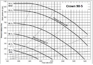
34 10 Flow Rate Graphs 33


35 34

36 35

37 We Bring Air to Life Fläkt Woods Group provides a full range of products and solutions for buildings ventilation, air treatment and industrial air movement Sales Offices available World Wide - See our website for details Sales Office Sales Office Head Office Fläkt Woods Ltd Unit 6240, Bishops Court Solihull Parkway Birmingham B37 7YB Tel: +44 (0) Fax: +44 (0) Fläkt Woods Ltd First Floor, Entrance 6, Crossford Court Dane Road, Sale, Cheshire M33 7BZ Tel: +44 (0) Fax: +44 (0) Fläkt Woods Ltd Axial Way Colchester Essex C04 5ZD Tel: +44 (0) Fax: +44 (0) Due to a policy of continuous development and improvement the right is reserved to supply products which may differ from those illustrated and described in this publication. Certified dimensions will be supplied on request on receipt of order. Copyright, Fläkt Woods Ltd, All rights reserved. No part of this publication may be produced in any material form by any means without the written permission of Fläkt Woods Ltd. Any unauthorised use of this data may result in legal proceedings. FWSAS/1113/404443
OPERATING AND COMMISSIONING MANUAL
 OPERATING AND COMMISSIONING MANUAL 2015/03 1 In compliance with the current norms, the machine should be installed only by a technical person qualified for this type of work. During installation, ensure
STRA-24 for chilled beams
 STRA- Installation and commissioning manual STRA- for chilled beams STRA- is the room controller for the pressure independent (Pi) and constant air volume chilled beams. It is possible to set different
APP EOLE4. Applicable to program versions TAC5 Version DT & DG 2.7.0
 APP EOLE4 Applicable to program versions TAC5 Version DT 2.8.2 & DG 2.7.0 2 THE APP EOLE4 INTERFACE This interface can be used on Android, IOS and PC. Download the app from the App Store/Google Play or
CONFIGURABLE HIGH-EFFICIENCY HEAT RECOVERY UNITS CADB/T-HE PRO-REG Series
 False-ceiling models CADB/T-HE 4 to 33 Heat Recovery Compact heat recovery unit with high-efficiency (up to 93%) counter-flow heat exchanger, EUROVENT certified. The casing is made from plasticised galvanised
ROOM CONTROLLER STRA-04 TECHNICAL CATALOGUE AND INSTALLATION
 ROOM CONTROLLER STRA-04 TECHNICAL CATALOGUE AND INSTALLATION 2 STRA-04 Room Controller - Technical catalogue and installation STRA-04 ROOM CONTROLLER FOR OPTIVENT DESCRIPTION STRA-04 is a preprogrammed
EXPERT 2V4SA. Temperature Controller. User s manual CLEAN MODE COMPENSATION HUMIDITY OUTSIDE TEMPERATURE
 CLEAN MODE Temperature Controller User s manual CURRENT CONDITIONS ROOM TEMPERATURE PROBE TEMPERATURE OUTSIDE TEMPERATURE RELATIVE HUMIDITY STATIC PRESSURE TIME / DATE SETTINGS SET POINT / CURVE MINIMUM
Model 2008 I Battery Operated Irrigation Timer with 3/4 in. Anti-Siphon Valve
 i n s t r u c t i o n m a n u a l Model 2008 I Battery Operated Irrigation Timer with 3/4 in. Anti-Siphon Valve Features Weekly or cyclical programming 4 start times per day in weekly program Irrigation
ECONET Fault and error manual
 Fault and error manual March 2009 Contents Basic data to get started...3 A Alarms 1. Ice alarm, GT 42...4 2. Frost alarm, GT 41...4 3. Pump alarm, P 40...5 4. Pressure alarm, GP 40...5 5. Liquid, temperature
ROOM CONTROLLER STRA-24 TECHNICAL CATALOUGE AND INSTALLATION
 ROOM CONTROLLER STRA-24 TECHNICAL CATALOUGE AND INSTALLATION 2 STRA-24 Room Controller for chilled beams - Technical catalouge and installation STRA-24 ROOM CONTROLLER FOR CHILLED BEAMS DESCRIPTION STRA-24
LK Control v.3 & LK Control v.3 - RA
 LK Control v.3 & LK Control v.3 - RA Design LK Control v. 3 and LK Control v.3 -RA is complete unit for outdoor temperature-compensated heat regulation, adapted and pre-programmed for LK s Floor Heating
Installation Guide. ECL Comfort 210 / 310, application A231 / A Table of Contents
 1.0 Table of Contents 1.0 Table of Contents... 1 1.1 Important safety and product information..................... 2 2.0 Installation... 4 2.1 Before you start.....................................................
Eco-Propel TM Variable Speed Pump Kit Instruction and Operation Manual, P/N: , Revision 1
 Eco-Propel TM Variable Speed Pump Kit Instruction and Operation Manual, P/N: 107065-01, Revision 1 March 03, 2017 Contents Introduction 2 Installation Pre-installation 3 Installation Procedure 4 Electrical
Safety & Installation Instructions
 Model 8120A & 8126A Digital Ventilation Controller Safety & Installation Instructions READ AND SAVE THESE INSTRUCTIONS Table of contents Safety Instructions... 3 Specifications... 4 Overview... 4 Mounting
FLÄKTGROUP PM-MOTOR WITH INTEGRATED FC 106 FREQUENCY CONVERTER
 FLÄKTGROUP PM-MOTOR WITH INTEGRATED FC 106 FREQUENCY CONVERTER INSTALLATION AND MAINTENANCE INSTRUCTIONS Risk of electric shock: Motor terminals may still be live if the impeller is rotating, even when
Quick guide. Plug-in fans GPPM with FC101_106 August 2014
 Quick guide Plug-in fans GPPM with FC101_106 August 2014 Fläkt Woods permanent magnet motors and speed controllers for plug fans GPPM 1. General Fläkt Woods offers a wide range of permanent magnet motors
MC200CAB/4 Integral Version
 Issue 2.2 Mar 2017 MC200CAB/4 Integral Version Industrial & Commercial Heating Systems. www.powrmatic.co.uk Setting Instructions WARNING: THIS APPLIANCE MUST BE EARTHED IMPORTANT: Reset from Lockout is
RVD120 RVD G2510. Installation. Place of installation. Electrical installation. Permissible cable lengths
 en Installation Instructions District heating and d.h.w. controller 74 39 68 G25 RVD2 RVD4 Keep these instructions with the controller! Installation Place of installation In a dry room, e.g. the heat exchanger
Ventilation in balance
 Ventilation in balance AIRLINQ - DIGITAL BMS PARAMETERS FOR MODBUS RTU RS485 BASIC INFORMATION The present document is only valid for air handling units with firmware version 6. or newer. The firmware
Ventilation in balance
 Ventilation in balance AIRLINQ - DIGITAL BMS PARAMETERS FOR BACNET TM /IP. BACNET TM MS/TP BASIC INFORMATION The present document is only valid for air handling units with firmware version 6. or newer.
Eco-Propel TM Variable Speed Pump Kit Instruction and Operation Manual, p/n Revision 0
 Eco-Propel TM Variable Speed Pump Kit Instruction and Operation Manual, p/n 107065-01 Revision 0 May 20, 2016 Contents Introduction 2 Installation Pre-installation 3 Installation Procedure 4 Electrical
AIR VOLUME TRANSMITTER / CONTROLLER IML
 1131.60en 03.04.2013 AIR VOLUME TRANSMITTER / CONTROLLER IML IML air volume transmitter is designed for detecting and controlling air volumes in air handling units and room spaces. Air volumes are calculated
RVD125/109 RVD145/109
 G2511 en Installation Instructions District heating and d.h.w. controller RVD125/109 RVD145/109 Installation without base Place of installation Compact station front or control panel front Permissible
ELIOS 25 DIGITAL CONTROL UNIT WITH LCD DISPLAY FOR THERMAL SOLAR SYSTEMS TDS 006 M00 0SE A
 ELIOS 25 DIGITAL CONTROL UNIT WITH LCD DISPLAY FOR THERMAL SOLAR SYSTEMS TDS 006 M00 0SE 012945A0 040906 1 MAIN FEATURES Power supply 230V~ ±10% 50Hz Backlit alphanumeric LCD display Management of 5 output
VEX500 (Everest XH) High Efficiency Bidirectional Fan Unit
 High Efficiency Bidirectional Fan Unit") High Efficiency Bidirectional Fan Unit VEX5 (Everest XH) Field of application Installation Advantages Description Range Technical details Aeraulic and electrical details Acoustic specifications Aldes Smart
High Efficiency Bidirectional Fan Unit VEX5 (Everest XH) Field of application Installation Advantages Description Range Technical details Aeraulic and electrical details Acoustic specifications Aldes Smart
SOLAR LIGHTING CONTROLLER SUNLIGHT MODELS INCLUDED IN THIS MANUAL SL-10 SL-10-24V SL-20 SL-20-24V
 SOLAR LIGHTING CONTROLLER OPERATOR S MANUAL SUNLIGHT MODELS INCLUDED IN THIS MANUAL SL-10 SL-10-24V SL-20 SL-20-24V 10A / 12V 10A / 24V 20A / 12V 20A / 24V 1098 Washington Crossing Road Washington Crossing,
MODEL ELC-12/40-CVM-D BATTERY CHARGER
 NATIONAL RAILWAY SUPPLY MODEL ELC-12/40-CVM-D BATTERY CHARGER Installing, Operating and Service Instructions for the ELC-12/40-CVM-D Solid State Charger PLEASE SAVE THESE IMPORTANT SAFETY AND OPERATING
Inlet Controller TC5-ITA USER'S MANUAL. M rev. 02 K rev. 00
 Inlet Controller TC5-ITA USER'S MANUAL M 890-00047 rev. 02 K 895-00458 rev. 00 TABLE OF CONTENTS PRECAUTIONS... 3 FEATURES... 4 LOCATION OF THE CONTROLS... 5 Status Leds...5 Internal Switches...6 INSTALLATION
Heat recovery units type GTDHR
 GTDHR Double flux - 4 m3/h AC 23V type GTDHR Double flux heat recovery unit high efficiency 9%. The range consists of 5 sizes and 6 types for air flow from up to 4 m³/h. Application Ventilation and heat
OPERATING AND COMMISSIONING INSTRUCTIONS
 MS-CVT-001 Ind H Maj. 11/06/2018 Créé par : JC Validé par : JC Page 1/17 Table des matières I. RECEIVING THE EQUIPMENT... 3 I.1. Checks on reception... 3 I.2. Unpacking... 3 I.3. Storing... 3 II. INSTALLATION...
Everest XV. ErP. High Efficiency HRV Fan Unit READY
 High Efficiency HRV Fan Unit ErP READY Field of application Installation Advantages Description Range Technical details Aeraulic and electrical details Acoustic specifications Aldes Smart Control system
MiG2 TIME SWITCHES. 1, 2 & 4 Channel, 365 Day, Energy Saving Time Switches
 MiG2 TIME SWITCHES 1, 2 & 4 Channel, 365 Day, Energy Saving Time Switches The MiG2 series of timers are programmable 365-day time-switches, incorporating: Multiple switching times per day Single and block
HIGH EFFICIENCY HEAT RECOVERY UNITS WITH ROTARY WHEEL RHE Series
 High efficient units up to 88% with rotary wheel, plug-fans with backward curved blades and EC external-rotor motor. Pre-configured control system for easy start-up. The casing is made of 5 mm, self-supporting
80W. Operating Manual. Dual Power. Intelligent Balance Charger LiPo/LiFe/LiIon: NiMH/NiCd: Pb: Charge Power: Charge Rate: Discharge Rate:
 80W Dual Power /LiFe/LiIon NiMH/NiCd Pb Charge Power Charge Rate Discharge Rate 1-6S 1-16S 2-20V 80W 0.1-10.0A 0.1-2.0A Intelligent Balance Charger Operating Manual - 2 - Please read this operating manual
Fault Codes. J control
 J control Timer Temp Fault Codes 12 11 10 9 8 7 6 5 4 3 2 1 30 29 28 27 26 25 24 23 22 21 20 Enter unit inspection mode by pushing the UP and DOWN buttons simultaneously for two seconds. Ensure that the
S D ST215 TAFFOR. ST215 Temperature Programmer User Handbook.
 TAFFOR S D ST215 ST215 Temperature Programmer User Handbook www.staffordinstruments.co.uk See separate handbook for Installation Instructions Issue: 1.000 ST215 Copyright User Handbook 2014 Stafford Instruments
Automatic Genset Controller, AGC-4 Display readings Push-button functions Alarm handling Log list
 OPERATOR'S MANUAL Automatic Genset Controller, AGC-4 Display readings Push-button functions handling Log list DEIF A/S Frisenborgvej 33 DK-7800 Skive Tel.: +45 9614 9614 Fax: +45 9614 9615 info@deif.com
ECONOMISER SERIES E2T USER MANUAL
 TURBO S.R.L. Electronic Control Systems for Dust Collectors e-mail: info@turbocontrols.it web: www.turbocontrols.it TEL. ++39 (0)362 574024 FAX ++39 (0)362 574092 ECONOMISER SERIES E2T USER MANUAL 24/06/2014
Silent centrifugal air heater hot water supply
 Large range : 5 to 120 Flows : 900 to 14000 m 3 /h Numerous accessories Design integrating perfectly in public buildings USE Operation in zones ES and S Extra silent and silent Forced air heating for premises
8 Troubleshooting and Maintenance
 8 Troubleshooting and Maintenance 8.1 Troubleshooting 8.1.1 Troubleshooting of LED Indicators See Tab. 7-4 State Descriptions of LED Indicators for the definition. Fault Type LED indicators and LCD screen
OPERATING AND COMMISSIONING INSTRUCTIONS
 FREETIME HEXAMOTION MS-CDF-010 Ind G Maj. 21/06/2018 Créé par : JC Validé par : AR Page 1/57 SUMMARY I. RECEIVING THE EQUIPMENT... 4 I.1. Checks on reception... 4 I.2. Unpacking... 4 I.3. Storing... 4
SB 2000 PUSH TO SEARCH NEXT STAG E. Aerotech, Inc. FORM: QM 1320
 Inlet Controller SB 2000 USER'S MANUAL AUTO OPEN MANUAL PUSH TO SEARCH NEXT STAG E CLOSE Aerotech, Inc. FORM: QM 1320 4215 Legion Dr. Mason, MI 48854-1036 USA Rev. 3, Sept. 1997 Ph. (517) 676-7070 Fax
CeraControl. Temperature Programmer User Handbook.
 CeraControl Temperature Programmer User Handbook www.potterycrafts.co.uk See separate handbook for Installation Instructions Issue: 1.01 CeraControl Copyright User 2014 Handbook Potterycrafts Ltd. Date:
Chiller. AQL/AQH 40 to 75. Air Cooled Water Chillers Cooling Only and Heat Pump Engineering Data Manual to 77.2 kw to 75.
 Chiller AQL/ to 75 Air Cooled Water Chillers Only and Heat Pump Engineering Data Manual.0 to 75.8 kw 39.9 to 77.2 kw Outstanding Strength Points R410A Refrigerant. New simpler refrigerant circuit layout.
RVD G2383en. Installation. - Compact station - Control cabinet (in the front, on the inner wall or on a
 4 319 2968 0 G2383en en Installation Instructions District heating controller for one heating circuit and d.h.w. RVD230 Installation Place of installation In a dry room, e.g. in the heat exchanger room
DMR 3005 WM ONE ZONE WIRELESS DIMMER RECEIVER
 E363518 DMR 3005 WM ONE ZONE WIRELESS DIMMER RECEIVER 20725 NE. 16 AVE. #A-33 MIAMI, FLORIDA 33179 Tel: (305) 652-2599 Fax: (305) 650-8812 www.lumiron.com Email: sales@lumiron.com 1 Benefits and Features
ESCONDIDO FIRE DEPT TRAINING MANUAL Section DRIVER OPERATOR Page 1 of 13 Pumps and Accessory Equipment Revised
 DRIVER OPERATOR Page 1 of 13 PUMPS AND ACCESSORY EQUIPMENT Pumps are designed for many different purposes. In order to understand the proper application and operation of a pump in a given situation, firefighters
HWP Protection Board
 February 2009 HWP Protection Board Features and Operation This board provides the system protection features necessary to keep our HWP (Water Sourced Heat Pump) units safe in the instances when they are
BATTERY BOOSTER/CHARGER MODEL NO: DIGICAR 900
 BATTERY BOOSTER/CHARGER MODEL NO: DIGICAR 900 PART NO: 6261205 OPERATION & MAINTENANCE INSTRUCTIONS LS0715 INTRODUCTION Thank you for purchasing this CLARKE Battery booster / charger which is suitable
MODEL ELC-12/60-D BATTERY CHARGER
 *32198* NATIONAL RAILWAY SUPPLY Installing, Operating and Service Instructions for the 12/60 Solid State Charger MODEL ELC-12/60-D BATTERY CHARGER PLEASE SAVE THESE IMPORTANT SAFETY AND OPERATING INSTRUCTIONS
ROOF FAN ROOFMASTER STEC
 AIR COMFORT AIR MOVEMENT ROOF FANS ROOF FAN ROOFMASTER STEC INSULATED VERSION» TECHNICAL CATALOGUE 2 STEC Roofmaster - Technical Catalogue CONTENTS GENERAL DESCRIPTION Application/specification... 3 Features...
PureSine 150/300 Pure Sine Wave Inverter User s Manual
 PureSine 150/300 Pure Sine Wave Inverter User s Manual 1. Important Safety Instructions WARNING! Before you install and use your Inverter, please read and follow these safety instructions. 1-1. General
USER GUIDE Digital Thermostat GUIDE D UTILISATION Thermostat digital Bedienungsanleitung Termostato digital 50-72
 BT D-01 1 2 USER GUIDE GB Digital Thermostat 4-25 GUIDE D UTILISATION F Thermostat digital 26-49 Bedienungsanleitung D Termostato digital 50-72 GUÍA DE USUARIO ES Termostato digital 74-97 GUIA DO UTILIZADOR
INSTALLATION, OPERATION & MAINTENANCE INSTRATIONS
 INSTALLATION, OPERATION & MAINTENANCE INSTRATIONS (27/6/13) Contents 1. GENERAL DESCRIPTION... 2 2. RECEIPT AND PREPARATION... 2 3. INSTALLATION... 2 3.1. REMOVAL OF ACCESS PANEL... 2 3.2. FIXING A PLINTH...
Installation Instructions
 H068A00 H069A00 H070A00 POWER EXHAUST ACCESSORY SINGLE PACKAGE ROOFTOP UNITS 12.5to25TONS Installation Instructions TABLE OF CONTENTS SAFETY CONSIDERATIONS... 1 GENERAL... 1 INSTALLATION... 2 Power Exhaust
HEXAMOTION RANGE HEAT RECOVERY
 HEAT RECOVERY HEXAMOTION RANGE Selfregulating and high efficiency (>8%) Heat Recovery Ventilation compact unit with high performance. Econological solution. Airflow from 1 to 8 m3/h CALADAIR I 1 rue de
TECHNICAL MANUAL. Inverter / Charger Combi. Combi SW 12V 1600VA Réf : PF Combi SW 24V 3800VA Réf : PF NOT_COMBI_SW-00
 TECHNICAL MANUAL EN Inverter / Charger Combi Combi SW 12V 1600VA Réf : PF.16088 Combi SW 24V 3800VA Réf : PF.16089 SAFETY PRECAUTIONS TO PREVENT ANY RISK OF ELECTRIC SHOCK OR FIRE, READ THIS MANUAL CAREFULLY
Rain+Birdt. Simple To Set Timer (SST) Setup & Operation Instructions. English RAIN BIRD ( ) or visit
 Setup & Operation Instructions. English RAIN BIRD ( ) or visit") Rain+Birdt Simple To Set r (SST) Setup & Operation Instructions English Installation...2 Tools and Supplies Needed...2 Step 1. Mount r...2 Step 2. Connect Power...2 Indoor r...2 Outdoor r...2 Step 3. Connect
Rain+Birdt Simple To Set r (SST) Setup & Operation Instructions English Installation...2 Tools and Supplies Needed...2 Step 1. Mount r...2 Step 2. Connect Power...2 Indoor r...2 Outdoor r...2 Step 3. Connect
SECOND GENERATION Use this guide with unit serial number prefix beginning with BWF using Terra Power separator.
 Technical Information and Diagnostic Guide for SECOND GENERATION Use this guide with unit serial number prefix beginning with BWF using Terra Power separator. This guide will assist you in becoming more
Temperature Controller. TC5+2V4SA Plus USER'S MANUAL
 Temperature Controller TC5+2V4SA Plus USER'S MANUAL NOTICE Every effort has been made to ensure that this manual is complete, accurate and up-to-date. The information contained in it is however subject
EGQ 212: Duct transducer, CO 2 and temperature
 Product data sheet 7.0 EGQ : Duct transducer, CO and temperature How energy efficiency is improved Measuring the CO concentration and temperature for energy-efficient, demand-controlled regulation of the
G2515. Installation. Place of installation. Electrical installation. Permissible cable lengths. Securing the controller to the base
 74 319 726 G2515 en Installation Instructions District heating controller for 2 heating circuits and d.h.w. RVD26 Keep these instructions with the controller! Installation Place of installation In a dry
EC200 ELECTRONIC CONTROL SYSTEM
 1 INTRODUCING THE EC200 ELECTRONIC CONTROL SYSTEM With the use of new technology and an innovative approach to user interfacing, the EC200 Power Control System provides a complete control solution for
VFC. Operating manual TROX air terminal units Type VFC volume flow controllers. General information 2. VFC series volume flow controllers
 Type volume flow controllers series volume flow controllers General information Correct use Safety notes Area of application Operating modes Product description Installation Commissioning and wiring 5
Digital Diesel Control Remote control panel for GENVERTER GV4 and GV7i
 OPERATING MANUAL Digital Diesel Control Remote control panel for GENVERTER GV4 and GV7i Art. nr. 40200801 WHISPER POWER BV ENGLISH: PAGE 1 Kelvinlaan 82 9207 JB Drachten NEDERLANDS: PAGINA 41 Netherlands
CAD O Integral. Air Handling Unit with Rotating Heat Exchanger INSTRUCTION MANUAL INSTALLATION WIRING COMMISSIONING MAINTENANCE
 INSTRUCTION MANUAL INSTALLATION WIRING COMMISSIONING MAINTENANCE ISO 9001 Qualité AFNOR CERTIFICATION ISO 14001 Environnement AFNOR CERTIFICATION CAD O Integral Air Handling Unit with Rotating Heat Exchanger
RVD110 RVD G2381en. Installation. Commissioning
 4 319 2788 0 G2381en en Installation Instructions District heating and d.h.w. controller RVD110 RVD130 Installation Place of installation In a dry room, e.g. the heat exchanger room Mounting choices: -
Assembly and Maintenance Manual Type ASNU
 Assembly and Maintenance Manual Type ASNU Hatschekstr.36 69126 Heidelberg Germany Tel +49(0)6221 30470 Fax +49(0)6221 304731 info@stieber.de www.stieber.de Date of issue: 30.05.2018 GB Revision: 0 U:\EngUsers\!ProduktDoku\1AAA_Einbauerklaerung_Wartungsanleitung_Konformitaetserklaerung\1AAA_Wartungsanleitungen\Orginal_Worddatei\_ASNU.docx
ACOUSTIC CABINET FANS FOR SUPPLY AIR APPLICATIONS CAIB/T PRO-REG Series
 ACOUSTIC CABINET FANS FOR SULY AIR ALICATIONS CAIB/T RO-REG Series Introduction of fresh air to commercial offices and industrial kitchens. Acoustic cabinet fan in galvanised sheet steel with reinforced
DIN Rail UPS DC UPS/Battery Detection System Model: BDS-DIN-UPS Installation/Operation Manual
 DIN Rail UPS DC UPS/Battery Detection System Model: BDS-DIN-UPS 24-10 Installation/Operation Manual Table of Contents Section Page Section Page Quick Start 2 1) General Information 4 Materials Provided
FPS- 80. Manual. Reverso Pumps, Inc. Ph: (954)
") FPS- 80 Manual Table of Contents System Overview... 1 Control Panel Overview... 2 Technical Specifications... 3 Electrical and Installation... Tank Diagrams... 5 Initial Setup... 6 Digital Timer Instructions:
FPS- 80 Manual Table of Contents System Overview... 1 Control Panel Overview... 2 Technical Specifications... 3 Electrical and Installation... Tank Diagrams... 5 Initial Setup... 6 Digital Timer Instructions:
Modulating Furnace Information. Warning on Meter Setting - Read First!
 Modulating Furnace Information Pressure Transducer Pressure DC Volts 0.00" 0.25 0.20" 0.63 0.25" 0.72 0.30" 0.82 0.35" 0.91 0.40" 1.00 0.45" 1.09 0.50" 1.19 0.55" 1.28 0.60" 1.38 0.65" 1.47 0.70" 1.56
General Information... 2
 VAV Flow Controller-Actuators CSP 5001/5002 Applications Guide General Information... 2 CSP 5001/5002 Overview...2 Controller, Sensor, and Thermostat Functions...3 Wiring...4 Air Flow Sensor Connection...4
Introduction. TyreGuard 400 Assembly. Unit Conversion DAVIES, CRAIG PTY LTD TYREGUARD
 Issue date: December 2012 DAVIES, CRAIG PTY LTD Introduction Congratulations on purchasing your new 400 TYRE PRESSURE MONITORING SYSTEM (TPMS). Please check the assembly list (opposite page) to ensure
Furnace Web Site FAQs. Pro Press 100 / Pro 100 / Pro 100 plus. Lift. Belt Noise
 Furnace Web Site FAQs Pro Press 100 / Pro 100 / Pro 100 plus Lift Belt Noise A Worn belt Over time the belt may become dry or worn due to heat and travel. Replace the belt Tight If the belt was recently
General Instructions and Inspection Instructions for Crane
 General Instructions General Instructions and Inspection Instructions for Crane Distributed by Ergonomic Partners Sales@ErgonomicPartners.com www.ergonomicpartners.com Tel: 314-884-8884 EN R_(EN)/1 --
Remote Engine Starter System I User s Information Manual
 Remote Engine Starter System I User s Information Manual A Few Words About Safety Your safety, and the safety of others, is very important. Operating this Remote Engine Starter System safely is an important
AUTOMATIC SPRINKLER TIMER
 AUTOMATIC SPRINKLER TIMER Owner s Manual PRT-4 / PRT-6 For use with standard 24 VAC automatic sprinkler valves. These timers are designed for use in any 110 VAC /60 Hz ±10% AC outlet (240 VAC, 50 HZ for
Heat Recovery Ventilation
 .book Page i Thursday, March 30, 2000 3:31 PM Heat Recovery Ventilation VAM 500EJ VAM 800EJ VAM1000EJ VAM2000EJ VAM500~1000EJ VAM2000EJ Table of Contents i .book Page ii Thursday, March 30, 2000 3:31 PM
Battery Operated Advanced Computerized Irrigation Controller Installation and Operating Instructions
 Battery Operated Advanced Computerized Irrigation Controller Installation and Operating Instructions This handbook provides the installation and operating instructions for the DC-1 and DC-4 controllers.
GRUNDFOS INSTRUCTIONS. Hydro MPC. Installation and operating instructions
 GRUNDFOS INSTRUCTIONS Hydro MPC Installation and operating instructions Declaration of Conformity We, Grundfos, declare under our sole responsibility that the products Hydro MPC, to which this declaration
c-go 12V/10A 12V/20A Power supply and battery charger Instruction manual
 c-go 12V/10A 12V/20A Power supply and battery charger GB Instruction manual 1 Index 1. Product description... 2 2. Safety advices... 3 3. Mounting and installation... 4 4. Operation... 5 5. Problem solving...
Dycon D2430 EN54-4 Fire Alarm Power Supply Series
 Dycon D2430 EN54-4 Fire Alarm Power Supply Series Technical Description Installation and Operating Manual Construction Product Regulation 0359-CPR-00434 Page 1 of 14 Contents 1. General... 3 1.1 Product
Battery Management Innovation. For 12-volt automotive starting batteries and starting/charging systems INSTRUCTION MANUAL
 Battery Management Innovation For 12-volt automotive starting batteries and starting/charging systems INSTRUCTION MANUAL ! CAUTION Because of the possibility of personal injury, always use extreme caution
BATTERY CHARGER-STARTER
 BATTERY CHARGER-STARTER MODEL NO: WBC240 & WBC400 PART NO: 6261505 & 6261515 OPERATION & MAINTENANCE INSTRUCTIONS GC0116 INTRODUCTION Thank you for purchasing this CLARKE Battery Charger/Starter. Please
PF3100 TROUBLESHOOTING SOLUTIONS TO COMMON PROBLEMS. v1.1 Revised Nov 29, 2016
 PF3100 TROUBLESHOOTING SOLUTIONS TO COMMON PROBLEMS v1.1 Revised Table of Contents 1 Common Alarms and Warnings... 1 2 Common Issues... 6 2.1 Communication problems... 6 2.1.1 Controller communication
24V 3A EN54 Ancillary Power Supply
 24V 3A EN54 Ancillary Power Supply Normal supply - green light on Fault condition - call Engineer Control relay - activated 3A Power Supply C-TEC Manufactured in England by C-Tec EN 54-4 : 1997 INSTALLATION
TC62D Installation Instructions
 TC62D Installation Instructions January 2007 This TC62D has a return water low temperature limit option. Using the low limit precludes using a room sensor because both sensors plug into the same port.
HEAVY DUTY BATTERY BOOSTERS / CHARGERS. MODEL Nos. BC185N & BC205N OPERATING INSTRUCTIONS
 HEAVY DUTY BATTERY BOOSTERS / CHARGERS MODEL Nos. BC185N & BC205N OPERATING INSTRUCTIONS 0614 Thank you for purchasing this CLARKE Battery Charger. These units are suitable for charging and boosting 12
QUOTATION BLADE 7 LX. Product code GEAL6S2BAA
 1 of 10 Mattei rotary vane compressors are the result of 90 years of investments in research and development to improve performance and lessen the impact on the environment. Designed for industrial continuous
- Wiring Brochure Universal Reset Module 422e
 - Wiring Brochure Universal Reset Module 422e W 422e 01/08 1 Information Brochure hoose controls to match application 2 Application Brochure Design your mechanical applications 3 Rough In Wiring Rough-in
SE8300 Series Installation Guide 24 Vac Low Voltage
 Installation Guide 24 Vac Voltage mercial and Hotel/Lodging HVAC Fan Coil Applications CONTENTS Installation 2 Configurable BI/UI Universal Inputs Overview 3 Setup Screen Display 3 Terminal Identification
Cooling mode. Temperature adjustment button. Override button. 24 VAC COM AN1 COM OPEN CLOSED T2/AN2 T2/COM T3 T3 COM SENSOR COM C-Over COM NSB
 TB6980/TB7980 1. Introduction The TB6980/TB7980 digital thermostats provide proportional plus integral individual space temperature control in zoned commercial HVAC systems such as hydronic and pressure
Compact System NRGS 11-2 NRGS Original Installation Instructions English
 Compact System NRGS 11-2 NRGS 16-2 EN English Original Installation Instructions 810366-05 1 Contents Important Notes Page Usage for the intended purpose...4 Safety note...4 LV (Low Voltage) Directive
Assembly and Maintenance Manual Type AS
 Assembly and Maintenance Manual Type AS Hatschekstr.36 69126 Heidelberg Germany Tel +49(0)6221 30470 Fax +49(0)6221 304731 info@stieber.de www.stieber.de Date of issue: 30.05.2018 GB Revision: 0 U:\EngUsers\!ProduktDoku\1AAA_Einbauerklaerung_Wartungsanleitung_Konformitaetserklaerung\1AAA_Wartungsanleitungen\Orginal_Worddatei\_AS.docx
Table of Contents 文管中心 發行章
 ST600-XXX Series Pure Sine Wave Power Inverter User s Manual Table of Contents 1. Important Safety Instructions 1-1 General Safety Precautions 1 1-2 Battery Precautions. 1 2. Basic Descriptions 2-1 Mechanical
LIGHT COMMERCIAL. Troublesooting
 LIGHT COMMERCIAL Troublesooting 2. 2.1 Display board 2.1.1 Icon explanation on indoor display board (Super slim cassette 24K). 2.1.2 Icon explanation on indoor display board (Compact cassette 12K, 18K).
Installation Instructions
 Installation Instructions Power Exhaust Part Numbers: CRPWREXH07A00 THROUGH CRPWREXH079A00 Conversion Package Numbers: CRPECONV005A00, CRPECONV006A00 CONTENTS Page SAFETY CONSIDERATIONS......................
DIN Rail UPS Model: DIN-UPS Installation/Operation Manual
 DIN Rail UPS Model: DIN-UPS 24-10 Installation/Operation Manual Table of Contents Section Page Section Page Quick Start 2 1) General Information 4 Materials Provided 4 Optional Equipment 4 2) Safety Information
BATTERY BOOSTER/CHARGER MODEL NO: DIGICAR 600
 BATTERY BOOSTER/CHARGER MODEL NO: DIGICAR 600 PART NO: 6261200 OPERATION & MAINTENANCE INSTRUCTIONS LS0815 INTRODUCTION Thank you for purchasing this CLARKE Battery booster / charger which is suitable
GRUNDFOS INSTRUCTIONS. Control HVAC. Installation and operating instructions. Other languages. net.grundfos.com/qr/i/
 GRUNDFOS INSTRUCTIONS Control HVAC Installation and operating instructions Other languages net.grundfos.com/qr/i/98800750 English (GB) English (GB) Installation and operating instructions Original installation