Gear Toolkit Tutorial
|
|
|
- Samuel Fisher
- 6 years ago
- Views:
Transcription


1 Gear Toolkit Tutorial
2 Copyright 2014 FunctionBay, Inc. All rights reserved User and training documentation from FunctionBay, Inc. is subjected to the copyright laws of the Republic of Korea and other countries and is provided under a license agreement that restricts copying, disclosure, and use of such documentation. FunctionBay, Inc. hereby grants to the licensed user the right to make copies in printed from of this documentation if provided on software media, but only for internal/personal use and in accordance with the license agreement under which the applicable software is licensed. Any copy made shall include the FunctionBay, Inc. copyright notice and any other proprietary notice provided by FunctionBay, Inc. This documentation may not be disclosed, transferred, modified, or reduced to any form, including electronic media, or transmitted or made publicly available by any means without the prior written consent of FunctionBay, Inc. and no authorization is granted to make copies for such purpose. Information described herein is furnished for general information only, is subjected to change without notice, and should not be construed as a warranty or commitment by FunctionBay, Inc. FunctionBay, Inc. assumes no responsibility or liability for any errors or inaccuracies that may appear in this document. The software described in this document is provided under written license agreement, contains valuable trade secrets and proprietary information, and is protected by the copyright laws of the Republic of Korea and other countries. UNAUTHORIZED USE OF SOFTWARE OR ITS DOCUMENTATION CAN RESULT IN CIVIL DAMAGES AND CRIMINAL PROSECUTION. Registered Trademarks of FunctionBay, Inc. or Subsidiary RecurDyn is a registered trademark of FunctionBay, Inc. RecurDyn /AutoDesign, RecurDyn /Professional, RecurDyn /SOLVER, RecurDyn /SOLID, RecurDyn /FLEX, RecurDyn /NodalFlex, RecurDyn /LINEAR, RecurDyn /CONTROL, RecurDyn /TRACK_HM, RecurDyn /TRACK_LM, RecurDyn /CHAIN, RecurDyn /MTT2D, RecurDyn /MTT3D, RecurDyn /BELT, RecurDyn /HAT, RecurDyn /HYDRAULIC, RecurDyn /Gear, RecurDyn /Tire are trademarks of FunctionBay, Inc. Third-Party Trademarks Windows and Windows NT are registered trademarks of Microsoft Corporation. ProENGINEER and ProMECHANICA are registered trademarks of PTC Corp. Unigraphics and I- DEAS are registered trademark of UGS Corp. SolidWorks is a registered trademark of SolidWorks Corp. AutoCAD is a registered trademark of Autodesk, Inc. CADAM and CATIA are registered trademark of Dassault Systems. FLEXlm is a registered trademark of GLOBEtrotter Software, Inc. All other brand or product names are trademarks or registered trademarks of their respective holders. Edition Note These documents describe the release information of RecurDyn V8R3. 2
3 Table of Contents Getting Started... 4 Objective... 4 Audience... 5 Prerequisites... 5 Procedures... 5 Creating the Planetary Gear Set Model... 6 Task Objective... 6 Creating a New Model and Gear Subsystem... 7 Customizing Settings... 8 Creating the Gears... 8 Arranging the Gears Importing the Planet Gear Holder Geometry Creating the Joints Creating the 2D Contacts Applying a Motion Input and a Torque Load Running a Simulation Studying Misalignment Effects Task Objective Switching to 3D Contacts Simulating and Viewing the 3D Contact Results Misaligning a Planet Gear Simulating the Misaligned Model and Comparing Results Helical Gears Task Objective Creating the Model
4 Chapter 1 Getting Started Objective In this tutorial, you will simulate some simple gear systems to become familiar with the RecurDyn Gear Toolkit. The first system will be a planetary gear set using spur gears. The effect of misaligning one of the gears will be studied. The second system will be two gear pairs, one using spur gears and the other using helical gears. This system will be used to compare the performance of the two different gear types. 4
5 Audience This tutorial is intended for intermediate users of RecurDyn who previously learned how to create geometry, joints, and force entities. All new tasks are explained carefully. Prerequisites You should first work through the 3D Crank-Slider and Engine with Propeller tutorials, or the equivalent. We assume that you have a basic knowledge of physics. Procedures The tutorial is comprised of the following procedures. The estimated time to complete each procedure is shown in the table. Procedures Time(minutes) Creating the Planetary Gear Set Model 20 Studying Misalignment Effects 15 Helical Gears 20 Total 55 Estimated Time to Complete This tutorial takes approximately 55 minutes to complete. 5
6 Chapter 2 Creating the Planetary Gear Set Model Task Objective Learn how to create a simple gear system. 20 minutes Estimated Time to Complete 6


7 Creating a New Model and Gear Subsystem To create a new model: 1. On your Desktop, double-click the RecurDyn tool. RecurDyn starts and the New Model window appears. 2. Enter PlanetaryGearSet as the Model Name. 3. Select OK. To create a new gear subsystem: 1. From the Toolbar, select the Wireframe button. 2. From the Subsystem Toolkit group in the Toolkit tab, click Gear. RecurDyn will bring you into the new Gear subsystem, and a new Gear tab will appear in the ribbon. 7


8 Customizing Settings You will now make some custom settings to the program and to the model. You will improve the graphic display of the model and results, and you will turn off the Shift when Pasting option to make the future modeling steps easier. To improve the graphic display of the model and results: 3. From Model Setting group in the Home tab, click Display. The Display dialog will be shown. 4. Check the box next to Graphical Quality. 5. Adjust the two slider bars to the right to improve the display quality. 6. Select the Advanced tab. 7. Under Force, make the following settings: Scale: 10 Color: Red To turn off Shift When Pasting 1. Deselect the checkbox next to Shift When Pasting. 2. Click OK. Creating the Gears To create the sun gear: 1. From the Gear group in the Gear tab, click Spur. 8
9 2. Select the point 0, 0, 0 in the Working window to define the center of the gear, or type the values into in the Input windows toolbar. The SpurGear dialog will appear. 3. Select the Geometry Data tab. 4. Set the Number of Teeth to Click Generate optimal arc segment. 6. Click OK. 7. In the Database Window, right-click on SpurGear1. 8. Select Rename. 9. Rename the gear to SunGear. The model should now appear as shown below. 9

10 To create the planet gears: 1. Repeat the steps above to create another spur gear, this time with 21 teeth, and named PlanetGear1. 2. In the Working window, select PlanetGear1, the gear you just created. 3. Type Ctrl-C to copy the gear. 4. Type Ctrl-V two times to create two more planet gears. You will move them to their correct location later. 5. Rename the other two planet gears to PlanetGear2, and PlanetGear3 using the Database Window rename capability. To create the outer ring gear: 6. From the Gear group in the Gear tab, click Int.Spur. 7. Select the point 0, 0, 0 in the Working window to define the center of the gear. The SpurGearInternal dialog will appear. 8. Select the Geometry Data tab. 9. Make the following settings, as shown at right. Number of Teeth: 72 Outer Diameter: Select Generate optimal arc segment. 11. Select OK. 12. Rename the gear to OuterRingGear. Your model should now appear as shown at right. 10


11 Arranging the Gears You will now move the planet gears into position so that their teeth engage correctly with the sun gear. To engage the first planet gear: 1. From the ViewControlToolbar, select the Grid On/Off button to turn the grid display on. 2. From the Working Plane group in the Home tab, change the Coordinate from Car (Cartesian) to Cyl (cylindrical), as shown at right. This will change the grid display as shown at right, so you can easily select points exactly at 120 and 240 from the center of the sun gear. 3. From the Assembly group in the Gear tap, click Assembly. 4. In the Working window, select SunGear as the base gear. 5. To select the action gear, in the Working window, right-click on the planet gears, and select Select List, as shown at right. A list of selectable entities will be brought up. 6. Select PlanetGear1 from the list and click OK. 11

12 7. For the Center Distance, enter Click the Auto Engagement button. 9. Click Close. Your model should now appear as shown below. 12

13 To engage the remaining two planet gears: 1. Repeat the assembly process, this time selecting PlanetGear2 as the action gear. 2. This time, in the Assembly dialog, to the right of Direction, select the Pt button. 13

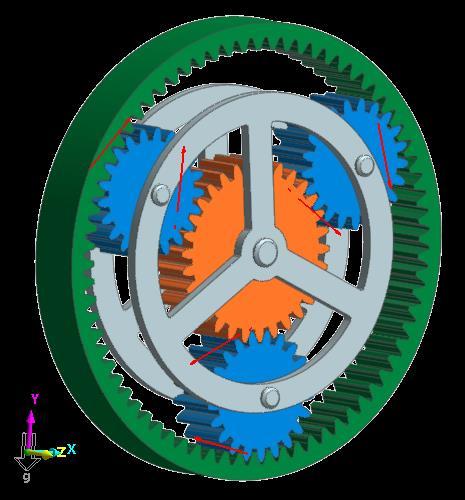
14 3. In the Working Window, select any grid point along the 120 line. 4. Again, select Auto Engagement and Close to move PlanetGear2 into place at 120 from the sun gear. 5. Repeat the assembly process for PlanetGear3, selecting any grid point along the 240 line. The model should now appear as shown below. At this point, the outer ring gear should look correctly sized to mesh with the planet gears, however, the angle of the gear is off by half a gear tooth, or ½ 360 / 72 teeth = 2.5. You will now rotate the outer ring gear by that amount to align it correctly with the planet gears. 14
15 To align the outer ring gear: 1. Select the OuterRingGear. 2. From the Viewcontroltoolbar, select the Object Control tool. 3. Select the Rotate tab. 4. Enter an angle of 2.5 degrees. 5. Click the Counterclockwise about Z- axis button. 6. Close the Basic Object Control dialog. The outer ring gear teeth should now align with those of the planet gears. 15


16 Importing the Planet Gear Holder Geometry You will now import geometry representing the planet gear holder. To import the planet gear holder: 1. Select System Button > Import. The Import dialog will appear. 2. Change the file type to ParaSolid File(*.x_t;*.x_b;*.xmt;*.xmt_bin). 3. Navigate to the Gear Tutorial directory and select the file PlanetGearCarrier.x_t. (The file location: <Install Dir> /Help /Tutorial /Toolkit /Gear /) 4. Click Open. 5. Rename the new body, ImportBody1, to PlanetGearCarrier. The model should now appear as shown below. 16
17 Creating the Joints You will now create several revolute joints to connect the gears to the various bodies. The outer ring gear will be fixed to ground. To create the joints: 1. From the Joint group in the Professional tab, click Fixed 2. Set the Creation Method toolbar to Body, Body, Point. 3. Select MotherBody as the base body by clicking in the background of the Working window. 4. Select OuterRingGear as the action body. 5. Enter 0, 0, 0 in the Input Window toolbar. 6. From the Joint group in the Professional tab, click Revolute. 7. Set the Creation Method toolbar to Body, Body, Point. 8. Select MotherBody as the base body. 9. Select PlanetGearCarrier as the action body. 10. Enter 0, 0, 0 in the Input Window toolbar. 11. Repeat Steps 7-11 to create revolute joints between the following bodies (use the center of mass markers to place the revolute joints at the centers of the gears). Joint Base Body Action Body RevJoint2 MotherBody SunGear RevJoint3 PlanetGearCarrier PlanetGear1 RevJoint4 PlanetGearCarrier PlanetGear2 RevJoint5 PlanetGearCarrier PlanetGear3 17
. 13.")
18 Creating the 2D Contacts For quick simulations, RecurDyn allows the creation of 2D contacts which take into account the profile shape of the gear teeth. You will now create 2D contacts between the gears. To create the 2D Contacts: 12. From the Contact group in the Gear tab, click Cur-Cur (2D Curve-to-Curve Contact). 13. Select SunGear as the base body. 14. Select PlanetGear1 as the action body. 15. Repeat Steps 1-4 above to create contacts between the following gears: Contact Base Body Action Body GearContact2 SunGear PlanetGear2 GearContact3 SunGear PlanetGear3 GearContact4 OuterRingGear PlanetGear1 GearContact5 OuterRingGear PlanetGear2 GearContact6 OuterRingGear PlanetGear3 You will now modify the contact parameters to improve simulation speed and improve results for this model. To modify the 2D Contact parameters: 1. In the Database Window, select GearContact1 GearContact6 by doing the following. a. Select GearContact1. b. Press and hold down the Shift key. c. Select GearContact6. 2. Right-click on one of the selected entities and select Property. A Properties dialog titled 6 entities will be displayed. 18


19 3. Select the Contact Characteristic tab. 4. Make the following settings. Spring Coefficient: Damping Coefficient: 1 5. Click OK. Applying a Motion Input and a Torque Load You will now apply a motion input to the planet gear carrier, and apply a resistive torque load onto the sun gear. To apply a motion input: 1. Open the Properties window for RevJoint1, the revolute joint between MotherBody and PlanetGearCarrier. 2. Select the Include Motion checkbox, and click the Motion button. 3. Select Velocity from the dropdown menu. 4. Click the EL button. 5. Click Create. 6. Enter Ex_planetGearCarrier_vel as the expression name. 7. Enter the following for the expression. 30D*step(time, 0, 0, 0.5, 1) 8. Click OK four times to exit out of all the dialog windows. To apply a resistive torque load: 1. From the Force group in the Professional tab, click Rot.Axial 19

20 2. Set the Creation Method toolbar to joint. 3. Use the Select List to select RevJoint2, the revolute joint between MotherBody and SunGear. 4. Open the Properties dialog for RotationalAxial1. 5. Click the EL button. 6. Click the Create button. 7. Enter Ex_sunGear_resistTorque for the expression name. 8. Enter -100 as the expression. 9. Click OK three times. Construction of the model is now complete and simulations can be run. 20

21 Running a Simulation You will now simulate the model and verify the observed gear ratio between the planet gear carrier and the sun gear. To run a simulation: 1. From the Simulation Type group in the Analysis tab, click Dyn/Kin 2. Make the following changes. End Time: 4 Step: 200 Plot Multiplier Step Factor: 5 3. Click Simulate. 4. When the simulation finishes, you can play the animation by clicking the Play button in the Toolbar. The animation should show the planetary gear system working smoothly with no problems. 21
22 Chapter 3 Studying Misalignment Effects Task Objective Observe how misaligning one of the planet gears affects the planetary gear system. 15 minutes Estimated Time to Complete 22

23 Switching to 3D Contacts Because you will be misaligning one of the gears, using the 2D contacts is no longer valid since you want to study the non-ideal behavior of the system caused by 3D interactions between the gears. Therefore the first step is to create new 3D gear contacts and deactivate the 2D contacts. To create the 3D gear contacts: 1. From the Contact group in the Gear tab, click Solid. 2. Select SunGear as the base body. 3. Select PlanetGear1 as the action body. 4. Repeat Steps 1-4 above to create contacts between the following gears. Contact Base Body Action Body GearContact3DR2 SunGear PlanetGear2 GearContact3DR3 SunGear PlanetGear3 GearContact3DR4 OuterRingGear PlanetGear1 GearContact3DR5 OuterRingGear PlanetGear2 GearContact3DR6 OuterRingGear PlanetGear3 You will now modify the contact parameters to improve simulation speed and improve results for this model. To modify the 3D Contact parameters: 1. In the Database Window, select GearContact3DR1 GearContact3DR6, using the Shift key as done before. 2. Right-click on one of the selected entities and select Property. A Properties dialog titled 6 entities will be displayed. 3. Under the 3D Gear Contact R tab, set No. of Max Contact Points to


24 4. Set the Force Display to Action. 5. In the Base Gear section, click the Contact Surface button. 6. Set the Plane Tolerance Factor to Click OK. 8. Repeat Steps 4-6 above for the Action Gear. 9. Select the Characteristic tab. 10. Change the Damping Coefficient to Click OK. To deactivate the 2D gear contacts: 1. In the Database Window, select GearContact1 GearContact6. 2. Right-click and select Inactive. 24

25 Simulating and Viewing the 3D Contact Results Before misaligning one of the gears, you will simulate the aligned case with 3D contacts which you will be able to use as a case to compare the misaligned case with. To simulate and view the results: 1. Simulate the model as done before. 2. When the simulation is done, play the animation results. The results should appear as shown below, with the contact force arrows appearing evenly distributed between all three planet gears. The contact force arrows should transition from tooth to tooth as the gears turn. 25

26 Misaligning a Planet Gear You will now save the model under a different name and then misalign the planet gear on the right side. To misalign a planet gear: 1. Select System Button > Save As. 2. Save the model as PlanetaryGearSet_misaligned.rdyn. 3. In the Database Window, right-click on PlanetGear1, and select Edit. You should now be in the body edit mode of PlanetGear1. 4. From the Database Window, select SpurGear1. 5. From the Toolbar, select the Basic Object Control tool. 6. Select the Rotate tab. 7. Enter an angle of 0.5 degrees. 8. Click the Counterclockwise About Y-Axis button. 9. Close the Basic Object Control dialog. From the Quick Access Toolbar, select the Exit button to exit the body edit mode and return to the gear subsystem. 26

27 Simulating the Misaligned Model and Comparing Results You will now simulate the model and then compare the results to those of the ideal model. To simulate the model: 1. Simulate the model as before, changing the End Time to 4 sec if needed. 2. When the simulation is complete, play back the animation results. You should see, as shown below, that the gear tooth contact forces become very high at certain points of the simulation depending on the orientation of the misaligned gear with respect to the sun and outer ring gears. To compare the results: 1. From the Plot group in the Analysis tab, click Plot. The plotting environment will be opened. 2. From the Import and Export in the Home tab, click Import. 3. Select the file PlanetaryGearSet.rplt and click OK. 27


28 4. To plot the driving torque of RevJoint1 for both sets of data. Right-click on PlanetaryGearSet_misaligned > Joints > RevJoint1 > Driving_Torque. Click Multi Draw. There should be an initial negative spike in the plot which will cause the y-axis scale to be too large. To adjust the y-axis scale: 5. Right-click on one of the y-axis number labels, and select Properties. 6. Make the following settings, as shown at right. Step: 100 Minimum: 0 Maximum: 500 Decimals: 0 7. Click OK. The plot should now appear similar to the one shown below. While both curves show periodic fluctuation with the frequency at which the gear teeth mesh, the driving torque for the misaligned model is noisier and also shows more fluctuation during the times when the misalignment has its greatest effect. 28
 Contact > Solid Contact > GearContact3DR4 > FM_SolidContact (contact between the outer")
29 8. From the Page group in the Home tab, click Add. 9. Repeat the steps above to plot the following data for both models. Contact > Solid Contact > GearContact3DR1 > FM_SolidContact (contact between the sun gear and planet gear 1) Contact > Solid Contact > GearContact3DR4 > FM_SolidContact (contact between the outer ring gear and planet gear 1) The plot should appear similar to the one shown below. Here, the periodic increase in contact force for the misaligned model can be seen easily, while the contact force for the aligned model is relatively constant. 29
30 Chapter 4 Helical Gears Task Objective Helical gears are often used in place of spur gears when noise reduction and smoothness of operation are of concern. In this chapter you will learn to create a helical gear pair, and compare its performance with an equivalent spur gear pair. 20 minutes Estimated Time to Complete 30


31 Creating the Model You will now create a model which will contain both a helical and a spur gear pair. When you are done with this set of steps, the model should appear as shown below. To create the spur gears 1. Create a new model, naming it SpurHelicalComp. 2. Create a gear subsystem within the new model. 3. From the Gear in the Gear tab, click Spur. 4. Select the point 0, 0, 0 as the gear center. 5. Select the Geometry Data tab. 6. Set the Pressure Angle to Click Generate optimal arc segment. 8. Click OK. 31

32 9. Make a copy of the above gear and translate it 50 mm in the +X direction. 10. Use the Assembly tool to mesh the gears with centers at 48 mm apart. To create the helical gears 11. From the Gear group in the Gear tab, click Helical. 12. Select the point 0, -60, 0 as the gear center. 13. Make the following settings, as shown at right. Module: Pressure Angle: 15 Helix Angle: 45 Note: To obtain a helical gear that is the same size as an equivalent spur gear, the module should be: module helical = module spur cos(helix angle) 14. Click Generate optimal arc segment. 15. Click OK. 16. Make a copy of the gear you just created and translate it 50 mm in the +X direction. 17. Open the Properties dialog for the gear you just copied. 18. Under the Geometry Data tab, change the Helix Angle to -45. In order for helix gears lying in the same plane to mesh, the helix angles must be of equal magnitude and opposite sign. 19. Click OK. 20. Use the Assembly tool to mesh the gears with centers at 48 mm apart. 32
33 To finish and simulate the model 1. Create four revolute joints at the centers of the gears in the following order (specifying MotherBody as the base bodies and the gears as the action bodies). Joint RevJoint1 RevJoint2 RevJoint3 RevJoint4 Gear Body SpurGear1 C1_SpurGear1 HelicalGear1 C1_HelicalGear1 2. Create the following expression, naming it Ex_drivGearDrive_vel. 600D*step(time, 0, 0, 0.5, 1) 3. Assign this as the driving expression for the velocity of RevJoint1 and RevJoint3. 4. Create two RotationalAxial forces applied at RevJoint2 and RevJoint4. 5. Create the following expression, naming it Ex_resistTorque Assign the above expression to the two RotationalAxial forces. 7. Create two Solid(3DContactR) contacts, one for the Spur gears and one for the Helical gears. Modify the contact settings as before, by making the following changes: Plane Tolerance Factor (for both base and action gears): 1 No. of Max Contact Points: 10 Force Display: Action Damping Coefficient: 1 8. Simulate the model, using the following settirngs. End Time: 1 Step: 200 Plot Multiplier Step Factor: 5 33
 of the gear to the back (-Z side), as shown below.")
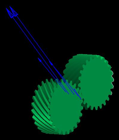
34 When the simulation stops, play the results animation. You should see from the contact force arrows that the contact points travel in a curved path from the front (+Z side) of the gear to the back (-Z side), as shown below. To understand what is happening in more detail, you can turn off the display of the helical gear on the right side. 9. In the Toolbar, select the Render Each Object button. 10. In the Database Window, right-click on HelicalGear1, and select Shade. 11. In the Database Window, right-click on C1_HelicalGear1, and select Hide. 34
 end of the gear tooth face and advances backwards to the other (-Z) end of the gear tooth face at which point that particular pair of gear teeth is no")
35 You should now be able to see, as shown at right, that each contact point is between its own pair of teeth, and that with the given gear specifications, four gear teeth pairs are always in contact. Each contact points begin at the front (+Z) end of the gear tooth face and advances backwards to the other (-Z) end of the gear tooth face at which point that particular pair of gear teeth is no longer in contact. This sliding nature of the contact points, as well as the distribution of contact over four points, is why helical gears are more quiet and operate more smoothly than spur gears. To compare the driving torque results 1. Open the plotting environment. 2. Plot the driving torque for RevJoint1 and RevJoint3. Joints > RevJoint1 > Driving_Torque Joints > RevJoint3 > Driving_Torque You should see a plot similar to the one below. The plot indicates that the driving torque is slightly smoother for the helical gear than the spur gear. 35
36 3. Plot the force in the Z direction exerted by ground on the driving gears: Joints > RevJoint1 > FZ_Reaction_Force Joints > RevJoint3 > FZ_Reaction_Force You should see a plot similar to the one shown below. This plot reveals one disadvantage of using helical gears, which is that due to the angle that the gear tooth faces are set at (the helix angle), an axial thrust is generated. This requires that special bearing be used which can withstand the axial load. Thanks for participating in this tutorial! 36
Introduction. Kinematics and Dynamics of Machines. Involute profile. 7. Gears
 Introduction The kinematic function of gears is to transfer rotational motion from one shaft to another Kinematics and Dynamics of Machines 7. Gears Since these shafts may be parallel, perpendicular, or
Lesson 8: A Compound Spur Gear Train
 Lesson 8: A Compound Spur Gear Train Goal: -Create Assembly -Create Proper Gear Mates -Create Motion Study -Graph Angular velocity of Output Gear MAKE SURE YOU ARE IN MILLIMETERS FOR THIS EXERCISE Creating
Model Library Power Transmission
 Model Library Power Transmission The Power Transmission libraries in SimulationX support the efficient modeling and analysis of mechanical powertrains as well as the simulation-based design of controlled
EE 370L Controls Laboratory. Laboratory Exercise #E1 Motor Control
 1. Learning Objectives EE 370L Controls Laboratory Laboratory Exercise #E1 Motor Control Department of Electrical and Computer Engineering University of Nevada, at Las Vegas To demonstrate the concept
Dynojet Research, Inc. All Rights Reserved. Optical RPM Sensor Installation Guide.
 1993-2001 Dynojet Research, Inc. All Rights Reserved.. This manual is copyrighted by Dynojet Research, Inc., hereafter referred to as Dynojet, and all rights are reserved. This manual, as well as the software
Copyright Notice. Small Motor, Gearmotor and Control Handbook Copyright Bodine Electric Company. All rights reserved.
 Copyright Notice Small Motor, Gearmotor and Control Handbook Copyright 1993-2003 Bodine Electric Company. All rights reserved. Unauthorized duplication, distribution, or modification of this publication,
KISSsoft Tutorial 012: Sizing of a fine pitch Planetary Gear set. 1 Task. 2 Starting KISSsoft
 KISSsoft Tutorial: Sizing of a fine pitch Planetary Gear set KISSsoft Tutorial 012: Sizing of a fine pitch Planetary Gear set For Release: 10/2008 kisssoft-tut-012-e-sizing-of-planetary-gear-set.doc Last
Tutorials Tutorial 3 - Automotive Powertrain and Vehicle Simulation
 Tutorials Tutorial 3 - Automotive Powertrain and Vehicle Simulation Objective This tutorial will lead you step by step to a powertrain model of varying complexity. The start will form a simple engine model.
Graphical representation of a gear
 Homework 4 Gears Gears are designed to transmit rotary motion. Often they are arranged in a gear train (meshed together). Gear trains provide a change in speed, torque (turning force) and direction (clockwise
ME Week 5 Project 1 Gear Generator
 1 Project 1 - Generate and Edit Gears In this project, you create spur and bevel gear sets. You edit the gears to provide clearance for the shafts. 1.1 Create Spur Gears In this section of the project,
KISSsoft 03/2018 Tutorial 7
 KISSsoft 03/2018 Tutorial 7 Roller bearings KISSsoft AG T. +41 55 254 20 50 A Gleason Company F. +41 55 254 20 51 Rosengartenstr. 4, 8608 Bubikon info@kisssoft.ag Switzerland www.kisssoft.ag Sharing Knowledge
KISSsoft 03/2013 Tutorial 2
 KISSsoft 03/2013 Tutorial 2 Cylindrical interference fit KISSsoft AG Rosengartenstrasse 4 8608 Bubikon Switzerland Tel: +41 55 254 20 50 Fax: +41 55 254 20 51 info@kisssoft.ag www.kisssoft.ag Contents
What are the functions of gears? What is gear?
 8//0 hapter seven Laith atarseh are very important in power transmission between a drive rotor and driven rotor What are the functions of gears? - Transmit motion and torque (power) between shafts - Maintain
TECHNOLOGY MECHANISMS
 TECHNOLOGY MECHANISMS 3º ESO IES CHAN DO MONTE URTAZA 1 WHAT IS A MECHANISM? Mechanism are devices that have been designed to make jobs easier. They all have certain things in common: They involve some
KISSsoft 03/2016 Tutorial 7
 KISSsoft 03/2016 Tutorial 7 Roller bearings KISSsoft AG Rosengartenstrasse 4 8608 Bubikon Switzerland Tel: +41 55 254 20 50 Fax: +41 55 254 20 51 info@kisssoft.ag www.kisssoft.ag Contents 1 Task... 3 1.1
RDS. For Windows TORSION SPRING CALCULATOR For ROLLING DOORS Version 4 REFERENCE MANUAL
 RDS For Windows TORSION SPRING CALCULATOR For ROLLING DOORS Version 4 REFERENCE MANUAL TABLE OF CONTENTS TABLE OF CONTENTS INTRODUCTION CREATING THE WORKING COPY INSTALLATION GETTING STARTED i iii iv v
CHAPTER 6 GEARS CHAPTER LEARNING OBJECTIVES
 CHAPTER 6 GEARS CHAPTER LEARNING OBJECTIVES Upon completion of this chapter, you should be able to do the following: Compare the types of gears and their advantages. Did you ever take a clock apart to
GEAR CONTENTS POWER TRANSMISSION GEAR TYPES OF GEARS NOMENCLATURE APPLICATIONS OF GEARS VELOCITY RATIO GEAR TRAINS EXAMPLE PROBLEMS AND QUESTIONS
 GEAR CONTENTS POWER TRANSMISSION GEAR TYPES OF GEARS NOMENCLATURE APPLICATIONS OF GEARS VELOCITY RATIO GEAR TRAINS EXAMPLE PROBLEMS AND QUESTIONS GEAR.. Power transmission is the movement of energy from
Chapter seven. Gears. Laith Batarseh
 Chapter seven Gears Laith Batarseh Gears are very important in power transmission between a drive rotor and driven rotor What are the functions of gears? - Transmit motion and torque (power) between shafts
Gearheads H-51. Gearheads for AC Motors H-51
 Technical Reference H-51 for AC Since AC motor gearheads are used continuously, primarily for transmitting power, they are designed with priority on ensuring high permissible torque, long life, noise reduction
KISSsoft 03/2013 Tutorial 15
 KISSsoft 03/2013 Tutorial 15 Bevel gears KISSsoft AG Rosengartenstrasse 4 8608 Bubikon Switzerland Tel: +41 55 254 20 50 Fax: +41 55 254 20 51 info@kisssoft.ag www.kisssoft.ag Contents 1 Starting KISSsoft...
GPK for Design and Rating of Industrial Gearboxes
 GPK for Design and Rating of Industrial Gearboxes KISSsys models: Bevel-Helical gear package includes KISSsys models for single bevel gearbox (right angle gearbox) and bevel gearboxes including one to
GPK for Design and Rating of Industrial Gearboxes
 KISSsoft AG - +41 55 254 20 50 Uetzikon 4 - +41 55 254 20 51 8634 Hombrechtikon - info@kisssoft.ag Switzerland - www.kisssoft.ag GPK for Design and Rating of Industrial Gearboxes KISSsys models: GPK geabox
Figure 1.1 "Bevel and hypoid gears" "Modules" Figure / August 2011 Release 03/2011
 KISSsoft Tutorial 015: Bevel Gears KISSsoft AG - +41 55 254 20 50 Uetzikon 4 - +41 55 254 20 51 8634 Hombrechtikon - info@kisssoft. AG Switzerland - www. KISSsoft. AG KISSsoft Tutorial: Bevel Gears 1 Starting
ME6401 KINEMATICS OF MACHINERY UNIT- I (Basics of Mechanism)
") ME6401 KINEMATICS OF MACHINERY UNIT- I (Basics of Mechanism) 1) Define resistant body. 2) Define Link or Element 3) Differentiate Machine and Structure 4) Define Kinematic Pair. 5) Define Kinematic Chain.
ME6401 KINEMATICS OF MACHINERY UNIT- I (Basics of Mechanism) 1) Define resistant body. 2) Define Link or Element 3) Differentiate Machine and Structure 4) Define Kinematic Pair. 5) Define Kinematic Chain.
Multibody Dynamics Simulations with Abaqus from SIMULIA
 Multibody Dynamics Simulations with Abaqus from SIMULIA 8.5.2008 Martin Kuessner Martin.KUESSNER@3ds.com Abaqus Deutschland GmbH 2 One Company, First Class Brands 3D MCAD Virtual Product Virtual Testing
CH#13 Gears-General. Drive and Driven Gears 3/13/2018
 CH#13 Gears-General A toothed wheel that engages another toothed mechanism in order to change the speed or direction of transmitted motion The gear set transmits rotary motion and force. Gears are used
Part VII: Gear Systems: Analysis
 Part VII: Gear Systems: Analysis This section will review standard gear systems and will provide the basic tools to perform analysis on these systems. The areas covered in this section are: 1) Gears 101:
Simscape Getting Started Guide. R2014a
 Simscape Getting Started Guide R2014a How to Contact MathWorks www.mathworks.com Web comp.soft-sys.matlab Newsgroup www.mathworks.com/contact_ts.html Technical Support suggest@mathworks.com bugs@mathworks.com
Chapter 8 Kinematics of Gears
 Chapter 8 Kinematics of Gears Gears! Gears are most often used in transmissions to convert an electric motor s high speed and low torque to a shaft s requirements for low speed high torque: Speed is easy
WORKSHOP 5: FLOAT-OVER ANALYSIS
 WORKSHOP 5: FLOAT-OVER ANALYSIS This workshop runs through the various phases of a deck float-over and mating process. A Topside is floating on a Barge, which is then winched into position between the
KISSsoft 03/2018 Tutorial 6
 KISSsoft 03/2018 Tutorial 6 Shaft editor KISSsoft AG T. +41 55 254 20 50 A Gleason Company F. +41 55 254 20 51 Rosengartenstr. 4, 8608 Bubikon info@kisssoft.ag Switzerland www.kisssoft.ag Sharing Knowledge
Customer Application Examples
 Customer Application Examples The New, Powerful Gearwheel Module 1 SIMPACK Usermeeting 2006 Baden-Baden 21. 22. March 2006 The New, Powerful Gearwheel Module L. Mauer INTEC GmbH Wessling Customer Application
Chapter 3. Transmission Components
 Chapter 3. Transmission Components The difference between machine design and structure design An important design problem in a mechanical system is how to transmit and convert power to achieve required
Deans Switch Microfluidics
 TRACE 1300 and TRACE 1310 Gas Chromatographs Deans Switch Microfluidics Installation Guide 31709740 Revision A June 2014 2014 Thermo Fisher Scientific Inc. All rights reserved. TRACE 1300, and TRACE 1310
UNIT -I. Ans: They are specified by the no. of strands & the no. of wires in each strand.
 VETRI VINAYAHA COLLEGE OF ENGINEERING AND TECHNOLOGY, THOTTIAM, NAMAKKAL-621215. DEPARTMENT OF MECHANICAL ENGINEERING SIXTH SEMESTER / III YEAR ME6601 DESIGN OF TRANSMISSION SYSTEM (Regulation-2013) UNIT
Simple Gears and Transmission
 Simple Gears and Transmission Contents How can transmissions be designed so that they provide the force, speed and direction required and how efficient will the design be? Initial Problem Statement 2 Narrative
Uponor MagiCAD Plugin. Juha Nakola
 Uponor MagiCAD Plugin Juha Nakola 2 (19) Contents CHAPTER 1. GENERAL... 3 ABOUT THIS DOCUMENT... 3 INSTALLING THE SOFTWARE... 3 Installation... 3 IMPORTANT HINTS... 3 Starting... 3 Adding circuits... 3
Introduction to Tube and PipeChapter1:
 Chapter 1 Introduction to Tube and PipeChapter1: This chapter introduces you to the tube and pipe environment in Autodesk Inventor Professional. Using the tube and pipe environment, you can create rigid
Design of Helical Gear and Analysis on Gear Tooth
 Design of Helical Gear and Analysis on Gear Tooth Indrale Ratnadeep Ramesh Rao M.Tech Student ABSTRACT Gears are mainly used to transmit the power in mechanical power transmission systems. These gears
KISSsys 03/2015 Instruction 010
 KISSsys 03/2015 Instruction 010 Positioning 07/04/2015 KISSsoft AG Rosengartenstrasse 4 8608 Bubikon Switzerland Tel: +41 55 254 20 50 Fax: +41 55 254 20 51 info@kisssoft.ag www.kisssoft.ag Contents 1.
KISSsoft 03/2017 Tutorial 15
 KISSsoft 03/2017 Tutorial 15 Bevel gears KISSsoft AG Rosengartenstrasse 4 8608 Bubikon Switzerland Tel: +41 55 254 20 50 Fax: +41 55 254 20 51 info@kisssoft.ag www.kisssoft.ag Contents 1 Starting KISSsoft...
View Numbers and Units
 To demonstrate the usefulness of the Working Model 2-D program, sample problem 16.1was used to determine the forces and accelerations of rigid bodies in plane motion. In this problem a cargo van with a
Paper Number: DETC
 Proceedings of the th ASME International Power Transmission and Gearing Conference DETC20 August 28-3, 20, Washington, DC, USA Paper Number: DETC20-48494 THE DYNAMIC SIMULATION AND ANALYSIS OF A CYCLOIDAL
Automotive NVH with Abaqus. About this Course
 Automotive NVH with Abaqus R 6.12 About this Course Course objectives Upon completion of this course you will be able to: Perform natural frequency extractions Perform sound radiation analyses (acoustics)
Automate Your Designs A Hands-On Experience
 Craig Ruchti, Solid Edge Field Support Applications Engineer Automate Your Designs A Hands-On Experience Solid Edge University 2014 May 12-14, Atlanta, GA, USA SOLID EDGE UNIVERSITY 2014 Re-imagine What
ME6601 DESIGN OF TRANSMISSION SYSTEMS
 SYED AMMAL ENGINEERING COLLEGE (Approved by the AICTE, New Delhi, Govt. of Tamilnadu and Affiliated to Anna University, Chennai) Established in 1998 - An ISO 9001:2008 Certified Institution Dr. E.M.Abdullah
Model Building Process
 Model Building Process SMT, CHARTWELL HOUSE, 67-69 HOUNDS GATE, NOTTINGHAM, NG1 6BB tel. +44 (0)115 941 9839 fax. +44 (0)115 958 1583 Adding a Shaft Right Click on New Design and select Shaft in Add the
Gear Tooth Geometry - This is determined primarily by pitch, depth and pressure angle
 Gear Tooth Geometry - This is determined primarily by pitch, depth and pressure angle Addendum: The radial distance between the top land and the pitch circle. Addendum Circle: The circle defining the outer
VALDYN 1-D Crankshaft modelling
 VALDYN 1-D Crankshaft modelling Tutorial www.ricardo.com 2 Contents Introduction Crankshaft torsional (1-D) modelling Crankshaft torsional analysis Crankshaft data Build model Define output plots Define
KISSsys 03/2014 Tutorial 3
 KISSsys 03/2014 Tutorial 3 Gear transmission with planetary differential KISSsoft AG Rosengartenstrasse 4 8608 Bubikon Switzerland Tel: +41 55 254 20 50 Fax: +41 55 254 20 51 info@kisssoft.ag www.kisssoft.ag
University of Jordan School of Engineering Mechatronics Engineering Department. Fluid Power Engineering Lab
 University of Jordan School of Engineering Mechatronics Engineering Department 0908464 09 The University of Jordan School of Engineering MECHATRONICS ENGINEERING DEPARTMENT EXPERIMENT N0. 1 Introduction
QuaSAR Quantitative Statistics
 QuaSAR Quantitative Statistics QuaSAR is a program that aids in the Quantitative Statistical Analysis of Reaction Monitoring Experiments. It was designed to quickly and easily convert processed SRM/MRM-MS
Simple Gears and Transmission
 Simple Gears and Transmission Simple Gears and Transmission page: of 4 How can transmissions be designed so that they provide the force, speed and direction required and how efficient will the design be?
Moments. It doesn t fall because of the presence of a counter balance weight on the right-hand side. The boom is therefore balanced.
 Moments The crane in the image below looks unstable, as though it should topple over. There appears to be too much of the boom on the left-hand side of the tower. It doesn t fall because of the presence
GEARBOXES. Gearboxes. Gearboxes. Gearbox is a mechanical device utilized to increase the output torque or change
 GEARBOXES Gearboxes Gearboxes Gearbox is a mechanical device utilized to increase the output torque or change the speed of a motor. The motor's shaft is attached to one end of the gearbox and through the
Toro Sprayer Calibration Tool
 Commercial Products Toro Sprayer Calibration Tool User Guide & Installation Instructions Toro Sprayer Calibration Tool 1 Table of Contents Introduction... 2 Program Instructions... 4 Toro Software End
11/23/2013. Chapter 13. Gear Trains. Dr. Mohammad Suliman Abuhiba, PE
 Chapter 13 Gear Trains 1 2 13.2. Types of Gear Trains 1. Simple gear train 2. Compound gear train 3. Reverted gear train 4. Epicyclic gear train: axes of shafts on which the gears are mounted may move
QuaSAR Quantitative Statistics
 QuaSAR Quantitative Statistics QuaSAR is a program that aids in the Quantitative Statistical Analysis of Reaction Monitoring Experiments. It was designed to quickly and easily convert processed SRM/MRM-MS
EPAS Desktop Pro Software User Manual
 Software User Manual Issue 1.10 Contents 1 Introduction 4 1.1 What is EPAS Desktop Pro? 4 1.2 About This Manual 4 1.3 Typographical Conventions 5 1.4 Getting Technical Support 5 2 Getting Started 6 2.1
Motor Tuning Instructions
 6/20/12 Motor Tuning Instructions Before you begin tuning: 1. Make sure Pro-Motion is installed. 2. Hook up motor drive, motor, and computer. - Connect motor drive to computer using a USB to Serial Com
OptimumDynamics. Computational Vehicle Dynamics Help File
 OptimumDynamics Computational Vehicle Dynamics Help File Corporate OptimumG, LLC 8801 E Hampden Ave #210 Denver, CO 80231 (303) 752-1562 www.optimumg.com Welcome Thank you for purchasing OptimumDynamics,
AssayMAP 96AM Wash Station. Maintenance Guide
 AssayMAP 96AM Wash Station Maintenance Guide Notices Agilent Technologies, Inc. 2018 No part of this manual may be reproduced in any form or by any means (including electronic storage and retrieval or
Quick Start User Guide
 Quick Start User Guide 2 Pipe Flow Expert Quick Start Guide Copyright Notice 2015 All Rights Reserved Daxesoft Ltd. Owner of PipeFlow.co.uk and PipeFlow.com Distribution Limited to Authorized Persons Only.
Working Model 2D Tutorial 2
 Working Model 2D: Tutorial 2 Example 11-10: A wheel with Diameter of 1.2m, mounted in a vertical plane, accelerates uniformly from rest at 3 rad/s 2 for five seconds, and then maintains uniform velocity
Theory of Machines II EngM323 Laboratory User's manual Version I
 Theory of Machines II EngM323 Laboratory User's manual Version I Table of Contents Experiment /Test No.(1)... 2 Experiment /Test No.(2)... 6 Experiment /Test No.(3)... 12 EngM323 Theory of Machines II
Hi-Z USB Wireless. Introduction/Welcome
 Hi-Z USB Wireless Introduction/Welcome Thank you for selecting the Hi-Z Antennas USB Wireless system. The Hi-Z USB Wireless system provides control functions from a personal computer to operate a Hi-Z
Structural Analysis of Differential Gearbox
 Structural Analysis of Differential Gearbox Daniel Das.A Seenivasan.S Assistant Professor Karthick.S Assistant Professor Abstract- The main aim of this paper is to focus on the mechanical design and analysis
(12) Patent Application Publication (10) Pub. No.: US 2007/ A1
 Patent Application Publication (10) Pub. No.: US 2007/ A1") (19) United States US 2007.0099.746A1 (12) Patent Application Publication (10) Pub. No.: US 2007/0099746A1 Hahlbeck (43) Pub. Date: MaV 3, 2007 9 (54) SELF ALIGNING GEAR SET Publication Classification
(19) United States US 2007.0099.746A1 (12) Patent Application Publication (10) Pub. No.: US 2007/0099746A1 Hahlbeck (43) Pub. Date: MaV 3, 2007 9 (54) SELF ALIGNING GEAR SET Publication Classification
Rack Installation Guide (Steelhead Series 3000, 5000, and 6000, and Interceptor Systems)
") Rack Installation Guide (Steelhead Series 3000, 5000, and 6000, and Interceptor Systems) 2007 Riverbed Technology, Incorporated. All rights reserved. The content of this manual is furnished on a RESTRICTED
Rack Installation Guide (Steelhead Series 3000, 5000, and 6000, and Interceptor Systems) 2007 Riverbed Technology, Incorporated. All rights reserved. The content of this manual is furnished on a RESTRICTED
Torque Module Installation and User Guide for model 250i Motorcycle Dynamometers.
 2000-2005 Dynojet Research, Inc. All Rights Reserved. Torque Module Installation and User Guide for model 250i Motorcycle Dynamometers. This manual is copyrighted by Dynojet Research, Inc., hereafter referred
(POWER TRANSMISSION Methods)
") UNIT-5 (POWER TRANSMISSION Methods) It is a method by which you can transfer cyclic motion from one place to another or one pulley to another pulley. The ways by which we can transfer cyclic motion are:-
UNIT-5 (POWER TRANSMISSION Methods) It is a method by which you can transfer cyclic motion from one place to another or one pulley to another pulley. The ways by which we can transfer cyclic motion are:-
Spur Gears. Helical Gears. Bevel Gears. Worm Gears
 Spur s General: Spur gears are the most commonly used gear type. They are characterized by teeth which are perpendicular to the face of the gear. Spur gears are by far the most commonly available, and
LinMot. Tutorial LinMot Designer NTI AG LinMot Bodenaeckerstr. 2 CH-8957 Spreitenbach
 LinMot Tutorial LinMot Designer 1.8.2 NTI AG LinMot Bodenaeckerstr. 2 CH-8957 Spreitenbach Tel.: +41 (0) 56 419 91 91 Fax: +41 (0) 56 419 91 92 office@linmot.com www.linmot.com LinMot Designer 1.8.2: Tutorial
Tutorial. Running a Simulation If you opened one of the example files, you can be pretty sure it will run correctly out-of-the-box.
 Tutorial PowerWorld is a great and powerful utility for solving power flows. As you learned in the last few lectures, solving a power system is a little different from circuit analysis. Instead of being
Dynojet Research, Inc. All Rights Reserved. Air Fuel Ratio Module Installation and User Guide.
 2014-2015 Dynojet Research, Inc. All Rights Reserved.. This manual is copyrighted by Dynojet Research, Inc., hereafter referred to as Dynojet, and all rights are reserved. This manual, as well as the software
1.6 Features of common gears
 1.6 Features of common gears Chapter 1.2 covered briefly on types of gear. The main gear features are explained here. Helical gear Helical gear has characteristics of transferability of larger load, less
Unit 1 Introduction to VEX and Robotics
 Unit Overview Unit 1 Introduction to VEX and Robotics VEX lab kits bring robotics into the classroom, making it a fun and educational experience for all. In this introductory unit, you review the kit and
Air Fuel Ratio Module and AFR-4 Pump Assembly Installation and User Guide.
 2007-2012 Dynojet Research, Inc. All Rights Reserved.. This manual is copyrighted by Dynojet Research, Inc., hereafter referred to as Dynojet, and all rights are reserved. This manual, as well as the software
Engineering Mechanics
 Engineering Mechanics Name Do nine of the following requirements from any topic (1-19) Engineering Mechanics 1. Many engineers use a computer-aided design (CAD) system to help them design their products.
Program Synchronic Index of In-line Geared Systems Introduction
 Program 60-151 Synchronic Index of In-line Geared Systems Introduction This TK Model calculates the synchronic index of an in-line geared transmission system. The synchronic index of a geared system is
Pre-lab Questions: Please review chapters 19 and 20 of your textbook
 Introduction Magnetism and electricity are closely related. Moving charges make magnetic fields. Wires carrying electrical current in a part of space where there is a magnetic field experience a force.
Torque Cell Installation Guide for Model 250i/250iP DynoWare RT Dynamometers.
 2015 Dynojet Research, Inc. All Rights Reserved. Torque Cell Installation Guide for Model 250i/250iP DynoWare RT Dynamometers. This manual is copyrighted by Dynojet Research, Inc., hereafter referred to
MeteorCalc SL. MeteorCalc SL is a CAD plugin for designing street lighting networks.
 MeteorCalc SL MeteorCalc SL is a CAD plugin for designing street lighting networks. The MeteorCalc SL software implements a full cycle of design works in the electrical networks of street lighting from
Thermal Analysis of Helical and Spiral Gear Train
 International Journal for Ignited Minds (IJIMIINDS) Thermal Analysis of Helical and Spiral Gear Train Dr. D V Ghewade a, S S Nagarale b & A N Pandav c a Principal, Department of Mechanical, GENESIS, Top-Kolhapur,
Introduction to Manual Transmissions & Transaxles
 Introduction to Manual Transmissions & Transaxles Learning Objectives: 1. Identify the purpose and operation of transmissions. 2. Describe torque and torque multiplication. 3. Determine gear ratios. 4.
F-39. Technical Reference
 Gearheads Role of the Gearhead The role of a gearhead is closely related to motor development. Originally, when the AC motor was a simple rotating device, the gearhead was mainly used to change the motor
Automotive NVH with Abaqus. Abaqus 2018
 Automotive NVH with Abaqus Abaqus 2018 About this Course Course objectives Upon completion of this course you will be able to: Perform natural frequency extractions Perform sound radiation analyses (acoustics)
Vertabelo Academy. Terms of Service PLEASE READ ALL OF THE FOLLOWING TERMS OF SERVICE BEFORE USING THIS WEBSITE A. General Terms
 Vertabelo Academy Terms of Service PLEASE READ ALL OF THE FOLLOWING TERMS OF SERVICE BEFORE USING THIS WEBSITE A. General Terms 1. These Terms of Service ("ToS") govern users access to and use of the Vertabelo
System 150 Auto Steer Setup Guide
 System 150 Auto Steer Setup Guide Part Number AGA3719 Rev 1.5 Copyright Topcon Precision Agriculture September, 2009 All contents in this manual are copyrighted by Topcon. All rights reserved. The information
KISSsoft 03/2018 Tutorial 4
 KISSsoft 03/2018 Tutorial 4 Bolt calculation according to VDI 2230 KISSsoft AG T. +41 55 254 20 50 A Gleason Company F. +41 55 254 20 51 Rosengartenstr. 4, 8608 Bubikon info@kisssoft.ag Switzerland www.kisssoft.ag
Program Center Distance Change
 Introduction Program 60-146--Center Distance Change When the coefficient of thermal expansion of the material used for gears is different from the coefficient for the mountg or housg material, it is necessary
Simulating Rotary Draw Bending and Tube Hydroforming
 Abstract: Simulating Rotary Draw Bending and Tube Hydroforming Dilip K Mahanty, Narendran M. Balan Engineering Services Group, Tata Consultancy Services Tube hydroforming is currently an active area of
Introduction to Abaqus/CAE. Abaqus 2018
 Introduction to Abaqus/CAE Abaqus 2018 About this Course Course objectives Upon completion of this course you will be able to: Use Abaqus/CAE to create complete finite element models. Use Abaqus/CAE to
St.MARTIN S ENGINEERING COLLEGE Dhulapally, Secunderabad
 St.MARTIN S ENGINEERING COLLEGE Dhulapally, Secunderabad-500 014 Subject: Kinematics of Machines Class : MECH-II Group A (Short Answer Questions) UNIT-I 1 Define link, kinematic pair. 2 Define mechanism
KINEMATICS OF MACHINARY UBMC302 QUESTION BANK UNIT-I BASICS OF MECHANISMS PART-A
 KINEMATICS OF MACHINARY UBMC302 QUESTION BANK UNIT-I BASICS OF MECHANISMS PART-A 1. Define the term Kinematic link. 2. Classify kinematic links. 3. What is Mechanism? 4. Define the terms Kinematic pair.
Mechanism Feasibility Design Task
 Mechanism Feasibility Design Task Dr. James Gopsill 1 Contents 1. Last Week 2. Types of Gear 3. Gear Definitions 4. Gear Forces 5. Multi-Stage Gearbox Example 6. Gearbox Design Report Section 7. This Weeks
Riverhawk Company 215 Clinton Road New Hartford NY (315) Free-Flex Flexural Pivot Engineering Data
 Free-Flex Flexural Pivot Engineering Data") Riverhawk Company 215 Clinton Road New Hartford NY (315)768-4937 Free-Flex Flexural Pivot Engineering Data PREFACE Patented Flexural Pivot A unique bearing concept for applications with limited angular
Riverhawk Company 215 Clinton Road New Hartford NY (315)768-4937 Free-Flex Flexural Pivot Engineering Data PREFACE Patented Flexural Pivot A unique bearing concept for applications with limited angular
Industrial Maintenance. Gear Drives 1. Courseware Sample F0
 Industrial Maintenance Gear Drives 1 Courseware Sample 36893-F0 Order no.: 36893-70 First Edition Revision level: 08/2015 By the staff of Festo Didactic Festo Didactic Ltée/Ltd, Quebec, Canada 2005 Internet:
TORQUE MULTIPLIERS. 25 Revolutions. Input 200 N.m. Output 5000 N.m Revolutions
 Handtorque - Multipliers TORQUE MULTIPLIERS 25 Revolutions Input 200 N.m = Torque = Velocity Output 5000 N.m 0.84 Revolutions What is a Torque Multiplier? A torque multiplier is a device that increases