Torque Cell Installation Guide for Model 250i/250iP DynoWare RT Dynamometers.
|
|
|
- Scarlett Hood
- 5 years ago
- Views:
Transcription
1
2 2015 Dynojet Research, Inc. All Rights Reserved. Torque Cell Installation Guide for Model 250i/250iP DynoWare RT Dynamometers. This manual is copyrighted by Dynojet Research, Inc., hereafter referred to as Dynojet, and all rights are reserved. This manual, and the software described in it, is furnished under license and may only be used or copied in accordance with the terms of such license. This manual is furnished for informational use only, is subject to change without notice, and should not be construed as a commitment by Dynojet. Dynojet assumes no responsibility or liability for any error or inaccuracies that may appear in this manual. Except as permitted by such license, no part of this manual may be reproduced, stored in a retrieval system, or transmitted, in any form or by any means, electronic, mechanical, recording, or otherwise, without the prior written permission of Dynojet. The Dynojet logo is a trademark of Dynojet Research, Inc. Any trademarks, trade names, service marks, or service names owned or registered by any other company and used in this guide are the property of their respective companies. Dynojet Research, Inc., 2191 Mendenhall Drive, North Las Vegas, Nevada 89081, USA. Printed in USA. Part Number: Version 2 (07/2015)
3 TABLE OF CONTENTS Chapter 1 Chapter 2 Torque Cell Installation Introduction Conventions Used In This Manual Technical Support Main Dyno Power Connecting and Disconnecting the Power Above Ground Dyno Connecting and Disconnecting the Power In Ground Dyno Accessing the Dyno Accessing the Dyno Above Ground Accessing the Dyno In Ground Load Cell Installation Routing the Load Cell Cable Routing the Load Cell Cable Above Ground Dyno Routing the Load Cell Cable In Ground Dyno Replacing the Covers Replacing the Covers Above Ground Dyno Replacing the Cover In Ground Dyno Load Cell Calibration Load Cell Calibration Torque Cell Installation Guide for Model 250i/250iP DynoWare RT Dynamometers i
4
5 CHAPTER 1 TORQUE CELL INSTALLATION The torque cell along with Dynojet Power Core software provides the technician with the ability to control vehicle RPM or speed at any throttle opening. Through our exclusive closed-loop software design, the vehicle is automatically held at your predetermined setting. Use the torque cell and Power Core software to measure real-time torque, and perform sweep, step and custom load simulation tests. This document provides instructions for installing the torque cell on a Dynojet Model 250i/250iP DynoWare RT Motorcycle Dynamometer (dyno) and calibrating the torque cell using Power Core software. To ensure safety and accuracy in the procedures, perform the procedures as they are described. Document Part Number: Version 2 Last Updated: This chapter is divided into the following categories: Introduction, page 1-2 Main Dyno Power, page 1-3 Accessing the Dyno, page 1-5 Load Cell Installation, page 1-9 Routing the Load Cell Cable, page 1-12 Replacing the Covers, page
6 CHAPTER 1 Introduction INTRODUCTION The torque cell, when added to Dynojet's market leading inertia dynamometer, results in a complete vehicle performance test. Before installing and calibrating your torque module, please take a moment to read this guide for installation instructions, features, and other important information. CONVENTIONS USED IN THIS MANUAL The conventions used in this manual are designed to protect both the user and the equipment. example of convention Bold description The Caution icon indicates a potential hazard to the dynamometer equipment. Follow all procedures exactly as they are described and use care when performing all procedures. The Warning icon indicates potential harm to the person performing a procedure and/or the dynamometer equipment. Highlights items you can select on in the software interface, including buttons and menus. TECHNICAL SUPPORT For assistance, please contact Dynojet Technical Support at , or write to Dynojet at 2191 Mendenhall Drive, North Las Vegas, NV Visit us on the World Wide Web at where Dynojet provides state of the art technical support, on-line shopping, and press releases about our latest product lines. 1-2
7 TORQUE CELL INSTALLATION Main Dyno Power MAIN DYNO POWER This section describes how to connect and disconnect the power to both the above ground and in ground dyno. CONNECTING AND DISCONNECTING THE POWER ABOVE GROUND DYNO Use the following steps to connect and disconnect power to the above ground dyno. Always turn the power off when connecting and disconnecting cables. 1 Use the main breaker to turn power on and off to the dyno. The main breaker is located inside the CPI door. When the handle is in the down position all power into the dyno is turned off. 2 Disconnect the power plug to ensure all power has been removed from the dyno before performing certain installation procedures. Components attached to and within the dynamometer operate with potentially lethal voltages. The power cord must be disconnected from the power source before servicing electrical components or wiring. power plug MC153 main breaker Figure 1-1: Main Dyno Power Above Ground Dyno Version 2 1-3
8 CHAPTER 1 Main Dyno Power CONNECTING AND DISCONNECTING THE POWER IN GROUND DYNO Use the following steps to connect and disconnect power to the in ground dyno. Always turn the power off when connecting and disconnecting cables. 1 Use the main breaker to turn power on and off to the dyno. The main breaker is located inside the CPI door. When the handle is in the down position all power into the dyno is turned off. 2 Disconnect the power plug to ensure all power has been removed from the dyno before installing the DynoWare RT electronics. Components attached to and within the dynamometer operate with potentially lethal voltages. The power cord must be disconnected from the power source before servicing electrical components or wiring. PD231 power plug main breaker Figure 1-2: Main Dyno Power In Ground Dyno 1-4
9 TORQUE CELL INSTALLATION Accessing the Dyno ACCESSING THE DYNO Installing the load cell requires access to the dyno and eddy current brake. This section will walk you through accessing both the above ground and in ground dyno. Make sure you have disconnected the power to the dyno before removing the covers. Refer to Main Dyno Power on page 1-3. ACCESSING THE DYNO ABOVE GROUND You will need to remove the tire carriage, center panel, and eddy current brake top cover in order to route the load cell cable to the eddy current brake driver. 1 Remove the four screws securing the bearing bracket to the tire carriage and set aside. 2 Using the hand wheel, or the power carriage, unscrew the bearing bracket and the carriage screw and set aside. 3 Remove the tire carriage by sliding the carriage under the carriage clamps toward the back of the dyno and set aside. tire carriage carriage clamp nut block carriage screw TC080 bearing bracket screws hand wheel Figure 1-3: Remove the Tire Carriage Version 2 1-5
10 CHAPTER 1 Accessing the Dyno 4 Remove the two 5/16-inch bolts and washers securing each of the carriage clamps and shims and set aside. 5 Remove the three carriage clamps and shims and set aside. 6 Remove the two 5/16-inch bolts and washers securing the nut block and shim and set aside. 7 Remove the nut block and shim and set aside. 8 Remove the six 1/4-20 x 5/8-inch pan head screws securing the center panel to the dyno carriage and set aside. 9 Remove the center panel and set aside. carriage clamp screw bolt washer shim nut block shim TC081 center panel Figure 1-4: Remove the Center Panel 1-6
11 TORQUE CELL INSTALLATION Accessing the Dyno 10 Remove the six screws securing the eddy current brake top cover and set aside. 11 Remove the brake top cover and set aside. brake top cover Figure 1-5: Remove the Brake Top Cover Version 2 1-7
12 CHAPTER 1 Accessing the Dyno ACCESSING THE DYNO IN GROUND brake cover You will need to remove the eddy current brake pit cover in order to route the load cell cable to the eddy current brake driver. 1 Remove the four 3/8-16 x 1/8-inch button-head flange screws securing the eddy current brake pit cover and set aside. 2 Remove the eddy current brake pit cover and set aside. PD245 Figure 1-6: Remove the Brake Pit Cover 1-8
13 TORQUE CELL INSTALLATION Load Cell Installation LOAD CELL INSTALLATION This section describes how to remove the existing bar on the eddy current brake and install the load cell. Use the following instructions for both the above ground and in ground dynos. You will need the following part: part description load cell and cable, above ground P/N load cell and cable, in ground P/N Verify the main dyno power is disconnected. Refer to Main Dyno Power on page 1-3 for more information. 2 Remove the two bolts and nuts securing the existing bar on the eddy current brake and remove the bar. Set the bolts and nuts aside. bar Figure 1-7: Remove the Existing Bar Version 2 1-9
14 CHAPTER 1 Load Cell Installation 3 Verify the eyelets on the load cell are spaced the same as the bar removed earlier. Adjust the load cell spacing by loosening the lock nut and turning the eyelet. bar eyelet lock nut distance must be the same Figure 1-8: Verify Load Cell Spacing 4 Secure the load cell to the mounting bracket using the two bolts and nuts removed earlier. load cell cable load cell Figure 1-9: Install the Load Cell Above Ground Dyno 1-10
15 TORQUE CELL INSTALLATION Load Cell Installation install the load cell (the brake is not shown for clarity) Figure 1-10: Install the Load Cell In Ground Dyno PD229 Version
16 CHAPTER 1 Routing the Load Cell Cable ROUTING THE LOAD CELL CABLE Use the following instructions to identify and route the load cell cable. cable load cell and cable above ground dyno load cell and cable in ground dyno brief routing description connects the load cell to the eddy current brake driver ROUTING THE LOAD CELL CABLE ABOVE GROUND DYNO 1 Route the load cell cable from the eddy current brake through the air hole in the drum bulkhead and over to eddy current brake driver. Make sure the load cell cable is clear of any power cables or hot or rotating objects. 2 Attach the load cell cable to the eddy current brake driver. 3 Secure the load cell cable with a zip tie to the underside of the carriage assembly bulkhead. DynoWare RT air hole in drum bulkhead eddy current brake driver load cell cable load cell MC158 Figure 1-11: Routing the Load Cell Cable Above Ground Dyno 1-12
17 TORQUE CELL INSTALLATION Routing the Load Cell Cable ROUTING THE LOAD CELL CABLE IN GROUND DYNO 1 Open the front panel of the CPI to access the eddy current brake driver. 2 Route the load cell cable from the eddy current brake, through the designated communications pit conduit, and attach to the eddy current brake driver inside the CPI. Note: Be sure to keep the power and communications cables in different pit conduits. DynoWare RT main module load cell cable route communications cables in designated conduit eddy current brake driver load cell control panel interface (CPI) air fuel ratio module (AFR) PD246 Figure 1-12: Routing the Load Cell Cable In Ground Dyno Version
18 CHAPTER 1 Replacing the Covers REPLACING THE COVERS Before replacing the covers, verify the load cell is installed and the load cell cable is routed to the eddy current brake driver. Before replacing the eddy current brake top cover, be sure to calibrate your load cell. Refer to Load Cell Calibration on page 2-2. REPLACING THE COVERS ABOVE GROUND DYNO 1 Secure the center panel to the dyno carriage using the six 1/4-20 x 5/8-inch pan head screws removed earlier. 2 Secure the nut block and shim using the two 5/16-inch bolts and washers removed earlier. 3 Secure each carriage clamps and shim using two 5/16-inch bolts and washers removed earlier, carriage clamp screw bolt washer shim nut block shim TC081 center panel Figure 1-13: Replace the Center Panel 1-14
19 TORQUE CELL INSTALLATION Replacing the Covers 4 Starting from the back of the dyno, slide the carriage under the carriage clamps. 5 Slide the carriage screw, bearing bracket, and the hand wheel toward the nut block until the carriage screw is touching the nut block. 6 Using the hand wheel, or the power carriage, screw the carriage through the nut block and into the screw support bracket. 7 Secure the bearing bracket to the carriage using four screws removed earlier. tire carriage carriage clamp nut block carriage screw TC080 bearing bracket screws hand wheel Figure 1-14: Replace the Tire Carriage Version
20 CHAPTER 1 Replacing the Covers 8 Secure the eddy current brake top cover using the six bolts removed earlier. Note: Before replacing the eddy current brake top cover, be sure to calibrate your load cell. Refer to Load Cell Calibration on page 2-2. eddy current brake cover EB242 Figure 1-15: Replace the Eddy Current Brake Top Cover 1-16
21 TORQUE CELL INSTALLATION Replacing the Covers REPLACING THE COVER IN GROUND DYNO brake cover Before replacing the eddy current brake pit cover, be sure to calibrate your load cell. Refer to Load Cell Calibration on page 2-2. Secure the eddy current brake pit cover using the four screws removed earlier. PD245 Figure 1-16: Replace the Brake Pit Cover Version
22

23 CHAPTER 2 LOAD CELL CALIBRATION This chapter will walk you through calibrating the load cell on both the above ground and in ground dynos. To ensure safety and accuracy in the procedures, perform the procedures as they are described. Torque Cell Installation Guide for Model 250i/250iP DynoWare RT Dynamometers 2-1
24 CHAPTER 2 Load Cell Calibration LOAD CELL CALIBRATION This section provides instructions for calibrating the load cell. Follow the directions on the screen exactly. Failure to perform the directions accurately will result in improper torque values. You will need the following parts: part description part description weight, 25 pounds (4) P/N calibration arm assembly P/N Verify the dyno is connected to power. Refer to Main Dyno Power on page Double-click the Power Core program icon. 3 Click Dyno Control from the Application Launcher. 4 Verify you are connected to the DynoWare RT main module. Note: For more information on connecting to the dyno electronics, refer to the Power Core Quick Start Guide (on your Power Core CD or at or the Power Core Online Help. 5 From the Configuration ribbon, click Load Cell Calibration. 6 Remove the calibration arm and mass if it is installed. 7 Release the dyno brake. Make sure the drums are free to rotate. Note: There should not be anything resting on the eddy current brake or the dyno drum during this procedure. 8 Click Next to zero the connected torque cell. Figure 2-1: Zero Calibration Window Torque Cell Installation Guide for Model 250i/250iP DynoWare RT Dynamometers 2-2

25 LOAD CELL CALIBRATION Load Cell Calibration 9 Using the drop-down arrow, set the index to zero. Note: Powersports Dynos have one load cell, leave the index set to zero. 10 Enter the calibration weight. This value is stamped into the calibration arm. bolt pattern closest to the end of the calibration arm Figure 2-2: Calibration Mass Window Enter the calibration number stamped near the bolt pattern at the end of the calibration arm in the Mass box. If you do not have enough room to use the bolt pattern closest to the end of the calibration arm, use the number stamped near the bolt pattern in the center of the arm. Note: Dynojet recommends you secure the calibration arm using the bolt pattern closest to the end of the arm unless space constraints in your dyno room do not allow you to. bolt pattern near the center of the calibration arm Figure 2-3: Calibration Arm Number Version 2 Torque Cell Installation Guide for Model 250i/250iP DynoWare RT Dynamometers 2-3
26 CHAPTER 2 Load Cell Calibration 11 Install the calibration arm and weights using the bolts at the end of the calibration arm. Note: If you do not have enough room to use the bolt pattern closest to the end of the calibration arm, use the bolt pattern in the center of the arm. Refer to Figure 2-6 for above ground dynos and Figure 2-7 for in ground dynos. 11a Secure the calibration arm to the eddy current brake by tightening the bolt using the handle. 11b Gently place the weights on the calibration arm. Note: Verify the calibration arm is not contacting the cover. The calibration weights are very heavy. The weights must be set on the arm gently or you could damage the load cell. weights weight support pin secure arm to brake by tightening handle TM074 Figure 2-4: Install the Calibration Arm and Weights Using the Bolt Pattern Closest to the End Above Ground Dyno Torque Cell Installation Guide for Model 250i/250iP DynoWare RT Dynamometers 2-4
27 LOAD CELL CALIBRATION Load Cell Calibration secure arm to brake by tightening handle weight support pin TM076 weights Figure 2-5: Install the Calibration Arm and Weights Using the Bolt Pattern Closest to the End In Ground Dyno Version 2 Torque Cell Installation Guide for Model 250i/250iP DynoWare RT Dynamometers 2-5
28 CHAPTER 2 Load Cell Calibration If you do not have enough room to use the bolt pattern closest to the end of the calibration arm, use the bolt pattern in the center of the arm as shown in Figure 2-6 for above ground dynos and for Figure 2-7 in ground dynos. weight support pin weights secure arm to brake by tightening handle TM075 Figure 2-6: Install the Calibration Arm and Weights Using the Bolt Pattern in the Center Above Ground Dyno Torque Cell Installation Guide for Model 250i/250iP DynoWare RT Dynamometers 2-6
29 LOAD CELL CALIBRATION Load Cell Calibration secure arm to brake by tightening handle weight support pin weights TM077 Figure 2-7: Install the Calibration Arm and Weights Using the Bolt Pattern in the Center In Ground Dyno Version 2 Torque Cell Installation Guide for Model 250i/250iP DynoWare RT Dynamometers 2-7
30 CHAPTER 2 Load Cell Calibration 12 With the calibration arm and weights secured, click Next to calibrate. 13 Remove the calibration arm and weights and click Finish. Figure 2-8: Finish Calibration Window 14 Confirm the calibration was successful. For more information refer to the Power Core Online Help. Torque Cell Installation Guide for Model 250i/250iP DynoWare RT Dynamometers 2-8
31
Torque Module Installation and User Guide for model 250i Motorcycle Dynamometers.
 2000-2005 Dynojet Research, Inc. All Rights Reserved. Torque Module Installation and User Guide for model 250i Motorcycle Dynamometers. This manual is copyrighted by Dynojet Research, Inc., hereafter referred
Dynojet Research, Inc. All Rights Reserved. Air Fuel Ratio Module Installation and User Guide.
 2014-2015 Dynojet Research, Inc. All Rights Reserved.. This manual is copyrighted by Dynojet Research, Inc., hereafter referred to as Dynojet, and all rights are reserved. This manual, as well as the software
Air Fuel Ratio Module and AFR-4 Pump Assembly Installation and User Guide.
 2007-2012 Dynojet Research, Inc. All Rights Reserved.. This manual is copyrighted by Dynojet Research, Inc., hereafter referred to as Dynojet, and all rights are reserved. This manual, as well as the software
Dynojet Research, Inc. All Rights Reserved. Tire Temperature Sensor Installation Guide
 1998-2006 Dynojet Research, Inc. All Rights Reserved. This manual is copyrighted by Dynojet Research, Inc., hereafter referred to as Dynojet, and all rights are reserved. This manual, as well as the software
Power Carriage Installation Guide
 Power Carriage Installation Guide 1999-2002 Dynojet Research, Inc. All Rights Reserved. 020116SD Dynojet Research, Inc. 200 Arden Drive Belgrade, MT 59714 2191 Mendenhall Drive North Las Vegas, NV 89031
Dynojet Research, Inc. All Rights Reserved. Optical RPM Sensor Installation Guide.
 1993-2001 Dynojet Research, Inc. All Rights Reserved.. This manual is copyrighted by Dynojet Research, Inc., hereafter referred to as Dynojet, and all rights are reserved. This manual, as well as the software
2006 Dynojet Research, Inc. All Rights Reserved. Spring Applied Air Release (SAAR) Brake Assembly Installation
 Brake Assembly Installation") 2006 Dynojet Research, Inc. All Rights Reserved. This manual is copyrighted by Dynojet Research, Inc., hereafter referred to as Dynojet, and all rights are reserved. This manual, as well as the software
2006 Dynojet Research, Inc. All Rights Reserved. This manual is copyrighted by Dynojet Research, Inc., hereafter referred to as Dynojet, and all rights are reserved. This manual, as well as the software
Maintenance Guide For Model 224, Model 224 with 4WD, Model 424x, and Model 248 Automotive Dynamometers.
 2004-2008 Dynojet Research, Inc. All Rights Reserved. Maintenance Guide For Model 224, Model 224 with 4WD, Model 424x, and Model 248 Automotive Dynamometers. This manual is copyrighted by Dynojet Research,
Control Panel Interface Upgrade Installation Guide For Model 200i and 250i Motorcycle Dynamometers Serial Number 202xxxx.
 2004 Dynojet Research, Inc. All Rights Reserved. Control Panel Interface Upgrade Installation Guide For Model 200i and 250i Motorcycle Dynamometers Serial Number 202xxxx. This manual is copyrighted by
Linx System with Atra Flex Installation for Model 424 Automotive Dynamometers
 2009-2018 Dynojet Research, Inc. All Rights Reserved. Linx System with Atra Flex Installation for Model 424 Automotive Dynamometers This manual is copyrighted by Dynojet Research, Inc., hereafter referred
Eddy Current Brake Installation and User Guide For Model 224 Above Ground Automotive Dynamometers.
 2004-2008 Dynojet Research, Inc. All Rights Reserved. Eddy Current Brake Installation and User Guide For Model 224 Above Ground Automotive Dynamometers. This manual is copyrighted by Dynojet Research,
Harley-Davidson and the Bar & Shield logo are among the trademarks of H-D Michigan, LLC.
 2010-2012 Dynojet Research, Inc. All Rights Reserved. Harley-Davidson JUMPSTART Intallation and User Guide This manual is copyrighted by Dynojet Research, Inc., hereafter referred to as Dynojet, and all
Eddy Current Brake Installation and User Guide For Model 224 Pit Automotive Dynamometers.
 2004-2005 Dynojet Research, Inc. All Rights Reserved. Eddy Current Brake Installation and User Guide For Model 224 Pit Automotive Dynamometers. This manual is copyrighted by Dynojet Research, Inc., hereafter
Installation Guide for Above Ground Model 224 Automotive Dynamometers.
 2005-2014 Dynojet Research, Inc. All Rights Reserved. Installation Guide for Above Ground Model 224 Automotive Dynamometers. This manual is copyrighted by Dynojet Research, Inc., hereafter referred to
Installation Guide for In Ground Model 224 Automotive Dynamometers.
 2014-2015 Dynojet Research, Inc. All Rights Reserved. Installation Guide for In Ground Model 224 Automotive Dynamometers. This manual is copyrighted by Dynojet Research, Inc., hereafter referred to as
Eddy Current Brake Installation and User Guide For In Ground Model 224 Automotive Dynamometers.
 2004-2008 Dynojet Research, Inc. All Rights Reserved. Eddy Current Brake Installation and User Guide For In Ground Model 224 Automotive Dynamometers. This manual is copyrighted by Dynojet Research, Inc.,
INSTALLATION GUIDE. Dynojet Research 2191 Mendenhall Drive Suite 105, North Las Vegas NV,
 INSTALLATION GUIDE www.dynojetwb2.com Dynojet Research 2191 Mendenhall Drive Suite 105, North Las Vegas NV, 89081 1-800-992-4993 2008 Dynojet Research, Inc. All Rights Reserved. Wideband 2 Installation
2016 POWERSPORTS DYNAMOMETER PRICELIST
 2016 POWERSPORTS DYNAMOMETER PRICELIST DYNAMOMETER AND DIAGNOSTIC TEST EQUIPMENT FEATURED DYNAMOMETER OF: Dynojet Research, Inc. 2191 Mendenhall Drive North Las Vegas, NV 89081 Tel (800) 992-3525 Int Tel
Sea Doo 4-Tec Supercharged 1500cc Watercraft (Throttle By Wire models) Dynojet CMDM-6212
 Dynojet CMDM-6212") 2009-2012 Sea Doo 4-Tec Supercharged 1500cc Watercraft (Throttle By Wire models) Dynojet CMDM-6212 2012 Dynojet Research, Inc. All Rights Reserved. 2009-2012 Sea Doo 4-Tec Supercharged 1500cc Watercraft
2009-2012 Sea Doo 4-Tec Supercharged 1500cc Watercraft (Throttle By Wire models) Dynojet CMDM-6212 2012 Dynojet Research, Inc. All Rights Reserved. 2009-2012 Sea Doo 4-Tec Supercharged 1500cc Watercraft
Motorcycle Dynamometer Installation Guide
 Motorcycle Dynamometer Installation Guide 1993-2002 Dynojet Research, Inc. All Rights Reserved. 020329SD Dynojet Research, Inc. 200 Arden Drive Belgrade, MT 59714 2191 Mendenhall Drive North Las Vegas,
Dynojet Research, Inc. All Rights Reserved. Installation Guide For the Kart and ATV Dynamometers.
 1993-2005 Dynojet Research, Inc. All Rights Reserved. Installation Guide For the Kart and ATV Dynamometers. This manual is copyrighted by Dynojet Research, Inc., hereafter referred to as Dynojet, and all
Automotive. Powersports. Accessories
 Dynamometer Catalog Automotive Powersports Accessories Hardware Software and Tuning POWERSPORTS Inertia Only Dynamometers Inertia Only Dynamometers Dynojet s cutting-edge engineering delivers the precise
PLEASE READ ALL DIRECTIONS BEFORE STARTING INSTALLATION
 Parts List 2009-2010 BV300 / Vespa 300GTS Installation Instructions 1 Power Commander FC 1 USB Cable 1 Installation Guide 2 Dynojet Decals 2 Velcro strips 1 Alcohol swab THE IGNITION MUST BE TURNED OFF
POWERSPORTS DYNAMOMETERS TEST EQUIPMENT
 DYNAMOMETER CATALOG POWERSPORTS DYNAMOMETERS TEST EQUIPMENT ACCESSORIES HARDWARE SOFTWARE AND TUNING Your Source For Professional Service Equipment PO Box 80897 Rancho Santa Margarita, CA 92688 Phone:
PLEASE READ ALL DIRECTIONS BEFORE STARTING INSTALLATION
 PARTS LIST 2009-2011 Yamaha R1 Installation Instructions 1 Power Commander 1 USB Cable 1 Installation Guide 2 Power Commander Decals 2 Dynojet Decals 2 Velcro strips 1 Dual Lock strip 1 Alcohol swab 1
Dynojet Research, Inc. All Rights Reserved. User Guide for AutoTune with the Power Vision.
 2012-2015 Dynojet Research, Inc. All Rights Reserved. User Guide for AutoTune with the Power Vision. This manual is copyrighted by Dynojet Research, Inc., hereafter referred to as Dynojet, and all rights
PLEASE READ ALL DIRECTIONS BEFORE STARTING INSTALLATION
 PARTS LIST 2009 MV Agusta Brutale 1078 Installation Instructions 1 Power Commander 1 USB Cable 1 Installation Guide 2 Power Commander Decals 2 Dynojet Decals 2 Velcro strips 1 Alcohol swab 1 O2 Optimizer
Model 200i Specifications Maximum Horsepower 750 HP. Drum Speed Accuracy : +/- 1/100th MPH
 The Model 200i continues the Dynojet tradition of providing a reliable, repeatable, consistent and easy to use chassis dyno for quick and accurate diagnosing of performance problems. The Model 200i offers
PLEASE READ ALL DIRECTIONS BEFORE STARTING INSTALLATION
 PARTS LIST 2014-2016 Can-Am Spyder RT & F3 Installation Instructions 1 Power Commander 1 USB Cable 1 Installation Guide 2 Power Commander Decals 2 Dynojet Decals 1 O2 Optimizer 2 Velcro strips 1 Alcohol
PLEASE READ ALL DIRECTIONS BEFORE STARTING INSTALLATION
 PARTS LIST 2015 Yamaha FJ-09 Installation Instructions 1 Power Commander 1 USB Cable 1 Installation Guide 2 Power Commander Decals 2 Dynojet Decals 3 Velcro strips 1 Alcohol swab 1 Posi-tap 1 O2 Optimizer
OPERATION AND MAINTENANCE
 Table of Contents GENERAL INFORMATION INTRODUCTION... 1 Operating Specifications... 1 FEATURES... 1 SAFETY PRECAUTIONS... 2 SET-UP... 2 OPERATION AND MAINTENANCE TESTING AN IGNITION MODULE OR IGNITION
POWERSPORTS DYNAMOMETER HARDWARE AND SOFTWARE
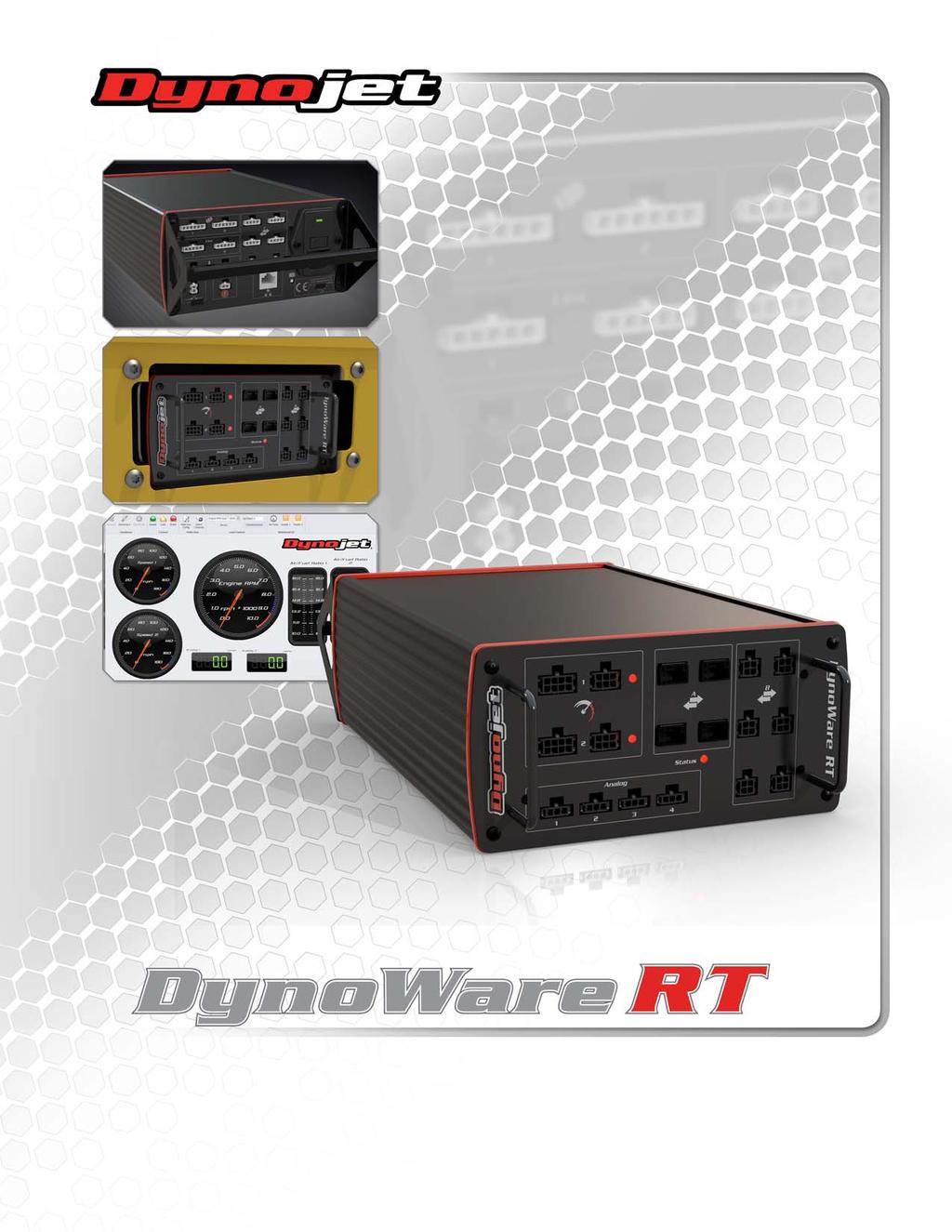
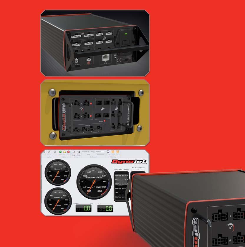
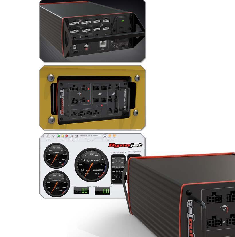
 POWERSPORTS DYNAMOMETER HARDWARE AND SOFTWARE DYNOWARE RT DYNAMOMETER HARDWARE DYNOWARE RT THE NEXT GENERATION OF DYNOJET DYNAMOMETER ELECTRONICS AND SOFTWARE HAS ARRIVED. DynoWare RT is the next generation
PLEASE READ ALL DIRECTIONS BEFORE STARTING INSTALLATION
 DYNOJET FUEL CONTROLLER PARTS LIST 1 Dynojet Fuel Controller 1 USB Cable 1 CD-ROM 1 Installation Guide 2 Dynojet Decals 2 Velcro 1 Alcohol swab 2008-2010 Honda SH125i/SH150i Installation Instructions PLEASE
PLEASE READ ALL DIRECTIONS BEFORE STARTING INSTALLATION
 PARTS LIST FUEL AND IGNITION 2011-2012 CanAm Spyder RT/RTS Installation Instructions 1 Power Commander 1 USB Cable 1 CD-ROM 1 Installation Guide 2 Power Commander Decals 2 Dynojet Decals 1 O2 optimizer
PLEASE READ ALL DIRECTIONS BEFORE STARTING INSTALLATION
 Parts List 2004-2007 Honda CBR1000RR Installation Instructions 1 Power Commander FC 1 USB Cable 1 Installation Guide 2 Dynojet Decals 2 Velcro 1 Alcohol swab THE IGNITION MUST BE TURNED OFF BEFORE INSTALLATION!
PLEASE READ ALL DIRECTIONS BEFORE STARTING INSTALLATION
 Parts List 2013-2014 Honda CBR600RR Installation Instructions 1 Power Commander FC 1 USB Cable 1 Installation Guide 2 Dynojet Decals 2 Velcro 1 Alcohol swab 1 O2 Optimizer THE IGNITION MUST BE TURNED OFF
Automotive. Accessories
 Dynamometer Catalog Automotive Powersports Accessories Hardware Software and Tuning POWERSPORTS Inertia Only Dynamometers Inertia Only Dynamometers Dynojet s cutting-edge engineering delivers the precise
PLEASE READ ALL DIRECTIONS BEFORE STARTING INSTALLATION
 PARTS LIST 2008-2009 Yamaha R6 Installation Instructions 1 Power Commander 1 USB Cable 1 CD-ROM 1 Installation Guide 2 Power Commander Decals 2 Dynojet Decals 2 Velcro 1 Alcohol swab 1 Posi-tap 1 O2 optimizer
PLEASE READ ALL DIRECTIONS BEFORE STARTING INSTALLATION
 PARTS LIST 2006-2011 Yamaha MT-03 Installation Instructions 1 Power Commander 1 USB Cable 1 Installation Guide 2 Power Commander Decals 2 Dynojet Decals 2 Velcro strips 1 Alcohol swab 1 O2 Optimizer THE
2008 Harley Davidson Touring
 2008 Harley Davidson Touring Installation Instructions Parts List 1 Power Commander 1 USB Cable 1 CD-ROM 1 Installation Guide 1 Power Adapter 2 Power Commander Decals 2 Dynojet Decals 2 O2 eliminators
EVO TM 200 AND EVO TM 400 LCD DISPLAY INSTALLATION GUIDE
 EVO TM 200 AND EVO TM 400 LCD DISPLAY INSTALLATION GUIDE The information in this publication is provided for reference only. While every effort has been made to ensure the reliability and accuracy of the
SmarTire TPMS Maintenance Hand Tool. Revision User Manual
 SmarTire TPMS Maintenance Hand Tool Revision 1.03 User Manual Page 2 Table of Contents FCC Compliance Label...4 User Interface Illustration...4 Introduction...5 Testing Tire Sensors...5 Main Menu...6 Main
Installation Guide For Model 248 Four Post Lift Automotive Dynamometers.
 1993-2005 Dynojet Research, Inc. All Rights Reserved. Installation Guide For Model 248 Four Post Lift Automotive Dynamometers. This manual is copyrighted by Dynojet Research, Inc., hereafter referred to
PLEASE READ ALL DIRECTIONS BEFORE STARTING INSTALLATION
 PARTS LIST 2009-2011 Moto Guzzi Stelvio Installation Instructions 1 Power Commander 1 USB Cable 1 Installation Guide 2 Power Commander Decals 2 Dynojet Decals 1 O2 Optimizer 3 Velcro strips 1 Alcohol swab
PLEASE READ ALL DIRECTIONS BEFORE STARTING INSTALLATION
 Parts List 2006-2014 Yamaha Stratoliner/Roadliner 2008-2013 Yamaha Raider Installation Instructions 1 Power Commander FC 1 USB Cable 1 Installation Guide 2 Dynojet Decals 2 Velcro 1 Alcohol swab 1 O2 Optimizer
PLEASE READ ALL DIRECTIONS BEFORE STARTING INSTALLATION
 Parts List 2008-2014 Honda CBR1000RR Installation Instructions 1 Power Commander FC 1 USB Cable 1 Installation Guide 2 Dynojet Decals 2 Velcro 1 Alcohol swab 1 O2 Optimizer THE IGNITION MUST BE TURNED
PLEASE READ ALL DIRECTIONS BEFORE STARTING INSTALLATION
 Parts List 2004-2014 Suzuki GSX-R600/GSX-R750 Installation Instructions 1 Power Commander FC 1 USB Cable 1 Installation Guide 2 Dynojet Decals 2 Velcro 1 Alcohol swab 1 O2 Optimizer THE IGNITION MUST BE
2009 Yamaha Apex Snowmobile
 PARTS LIST 2009 Yamaha Apex Snowmobile Installation Instructions quantity description 1 power commander 1 USB cable 1 cd-rom 1 installation guide 2 power commander decals 2 dynojet decals 2 velcro strip
PLEASE READ ALL DIRECTIONS BEFORE STARTING INSTALLATION
 PARTS LIST 2006-2007 Yamaha R6 Installation Instructions 1 Power Commander 1 USB Cable 1 Installation Guide 2 Power Commander Decals 2 Dynojet Decals 2 Velcro strips 1 Alcohol swab 1 Posi-tap THE IGNITION
PLEASE READ ALL DIRECTIONS BEFORE STARTING INSTALLATION
 PARTS LIST 2010-2012 MV Agusta Brutale 1090 Installation Instructions 1 Power Commander 1 USB Cable 1 Installation Guide 2 Power Commander Decals 2 Dynojet Decals 2 Velcro strips 1 Dual Lock strip 1 Alcohol
PLEASE READ ALL DIRECTIONS BEFORE STARTING INSTALLATION
 Parts List 2008-2011 Yamaha TMax 500 Installation Instructions 1 Power Commander FC 1 USB Cable 1 Installation Guide 2 Dynojet Decals 2 Velcro 1 Alcohol swab THE IGNITION MUST BE TURNED OFF BEFORE INSTALLATION!
PLEASE READ ALL DIRECTIONS BEFORE STARTING INSTALLATION
 PARTS LIST 2009-2010 MotoGuzzi Stelvio I n s t a l l a t i o n I n s t r u c t i o n s 1 Power Commander 1 USB Cable 1 CD-ROM 1 Installation Guide 2 Power Commander Decals 2 Dynojet Decals 1 O2 optimizer
PLEASE READ ALL DIRECTIONS BEFORE STARTING INSTALLATION
 PARTS LIST 2006-2008 MotoGuzzi Griso 1100 I n s t a l l a t i o n I n s t r u c t i o n s 1 Power Commander 1 USB Cable 1 CD-ROM 1 Installation Guide 2 Power Commander Decals 2 Dynojet Decals 1 O2 optimizer
PLEASE READ ALL DIRECTIONS BEFORE STARTING INSTALLATION
 PARTS LIST 2013-2014 Honda CB500 / CBR500R Installation Instructions 1 Power Commander 1 USB Cable 1 Installation Guide 2 Power Commander Decals 2 Dynojet Decals 2 Velcro strips 1 Alcohol swab 1 Posi-tap
2011 Yamaha Apex Snowmobile
 PARTS LIST 2011 Yamaha Apex Snowmobile Installation Instructions quantity description 1 power commander 1 USB cable 1 cd-rom 1 installation guide 2 power commander decals 2 dynojet decals 2 velcro strip
2009 Harley Davidson Dyna Models
 Parts List 2009 Harley Davidson Dyna Models Installation Instructions 1 Power Commander 1 USB Cable 1 CD-ROM 1 Installation Guide 2 Power Commander Decals 2 Dynojet Decals 2 Velcro Strip 1 Alcohol Swab
PLEASE READ ALL DIRECTIONS BEFORE STARTING INSTALLATION
 Parts List 2009-2014 Yamaha YFZ450 R/X Installation Instructions 1 Power Commander FC 1 USB Cable 1 Installation Guide 2 Dynojet Decals 2 Velcro 1 Alcohol swab THE IGNITION MUST BE TURNED OFF BEFORE INSTALLATION!
PLEASE READ ALL DIRECTIONS BEFORE STARTING INSTALLATION
 PARTS LIST 2010 MV Agusta Brutale 1090 Installation Instructions 1 Power Commander 1 USB Cable 1 CD-ROM 1 Installation Guide 2 Power Commander Decals 2 Dynojet Decals 2 Velcro 1 Dual Velcro 1 Alcohol swab
Version 1.0 Copyright DC-RPM-iBox User Manual
 Version 1.0 Copyright 2012 DC-RPM-iBox User Manual D Y N O C O M S E R I E S C H A S S I S D Y N A M O M E T E R S DC-RPM-iBox User Manual Copyright This manual is copyrighted by Dynocom Industries, Inc.,
Lamp House with 2.5 kw lamp
 Lamp House with 2.5 kw lamp Installation manual For HDX series R9864130 R5905109/04 27/05/2014 Barco nv, Events Noordlaan 5, B-8520 Kuurne Phone: +32 56.36.82.11 Fax: +32 56.36.88.24 Support: www.barco.com/esupport
PLEASE READ ALL DIRECTIONS BEFORE STARTING INSTALLATION
 PARTS LIST 2010-2011 MotoGuzzi V7 Installation Instructions 1 Power Commander 1 USB Cable 1 CD-ROM 1 Installation Guide 2 Power Commander Decals 2 Dynojet Decals 1 O2 optimizer 2 Velcro 1 Alcohol swab
SmarTire TPMS Maintenance Hand Tool. Revision User Manual
 SmarTire TPMS Maintenance Hand Tool Revision 1.04 User Manual Page 2 Table of Contents FCC Compliance Label... 4 User Interface Illustration... 4 Introduction... 5 Testing Tire Sensors... 5 Main Menu...
Harley Davidson Softail
 Parts List 2001-2006 Harley Davidson Softail Installation Instructions 1 Power Commander 1 USB Cable 1 CD-ROM 1 Installation Guide 2 Power Commander Decals 2 Dynojet Decals 3 Dual lock Velcro Strip 1 Zip
PLEASE READ ALL DIRECTIONS BEFORE STARTING INSTALLATION
 Parts List Husqvarna 250, 310, 450, 510, 610, and 630 Models Installation Instructions 1 Power Commander FC 1 USB Cable 1 Installation Guide 2 Dynojet Decals 2 Velcro 1 Alcohol swab 1 Posi-tap 1 O2 Optimizer
PLEASE READ ALL DIRECTIONS BEFORE STARTING INSTALLATION
 PARTS LIST 2007-2013 Arctic Cat 800cc and 1000cc Snowmobiles Installation Instructions 1 Power Commander 1 USB Cable 1 CD-ROM 1 Installation Guide 2 Power Commander Decals 2 Dynojet Decals 2 Velcro Strips
PLEASE READ ALL DIRECTIONS BEFORE STARTING INSTALLATION
 PARTS LIST FUEL AND IGNITION 2008-2011 Kawasaki Brute Force 750 Installation Instructions 1 Power Commander 1 USB Cable 1 CD-ROM 1 Installation Guide 2 Power Commander Decals 2 Dynojet Decals 2 Velcro
Lamp kit. Installation manual SIM 7 series R
 Lamp kit Installation manual SIM 7 series R9841805 R59770113/01 12/06/2009 Barco nv Simulation Division Noordlaan 5, B-8520 Kuurne Phone: +32 56.36.82.11 Fax: +32 56.36.84.86 E-mail: info@barco.com Visit
PLEASE READ ALL DIRECTIONS BEFORE STARTING INSTALLATION
 PARTS LIST 2007 Harley Davidson Touring Models Installation Instructions 1 Power Commander 1 USB Cable 1 Installation Guide 2 Power Commander Decals 2 Dynojet Decals 2 Zip-ties 2 O2 Optimizers THE IGNITION
2004, 2008 Autosoft, Inc. All rights reserved.
 Copyright 2004, 2008 Autosoft, Inc. All rights reserved. The information in this document is subject to change without notice. No part of this document may be reproduced, stored in a retrieval system,
ARCTIC CAT M8, M1000, F8, AND F1000 SNOWMOBILES INSTALLATION INSTRUCTIONS
 2007-2009 ARCTIC CAT M8, M1000, F8, AND F1000 SNOWMOBILES INSTALLATION INSTRUCTIONS PARTS LIST quantity description button adjustment display 1 power commander 1 USB A to mini B cable 1 cd-rom 1 installation
PLEASE READ ALL DIRECTIONS BEFORE STARTING INSTALLATION
 PARTS LIST 2004-2007 Honda CBR1000RR I n s t a l l a t i o n I n s t r u c t i o n s 1 Power Commander 1 USB Cable 1 CD-ROM 1 Installation Guide 2 Power Commander Decals 2 Dynojet Decals 2 Velcro 1 Alcohol
PLEASE READ ALL DIRECTIONS BEFORE STARTING INSTALLATION
 PARTS LIST FUEL AND IGNITION 2012 Polaris RZR 570 Installation Instructions 1 Power Commander 1 USB Cable 1 CD-ROM 1 Installation Guide 2 Power Commander Decals 2 Dynojet Decals 2 Velcro 1 Alcohol swab
Why is a Dynojet Dyno the most accurate & consistent chassis Dyno you can buy (at any price)? Customer Support. Durability.
? Customer Support. Durability.") Why is a Dynojet Dyno the most accurate & consistent chassis Dyno you can buy (at any price)? Durable and maintenance free design Large diameter precision balanced drum No maintenance or re-calibration
Why is a Dynojet Dyno the most accurate & consistent chassis Dyno you can buy (at any price)? Durable and maintenance free design Large diameter precision balanced drum No maintenance or re-calibration
PLEASE READ ALL DIRECTIONS BEFORE STARTING INSTALLATION
 PARTS LIST 2012-2013 Ducati Diavel Installation Instructions 1 Power Commander 1 USB Cable 1 CD-ROM 1 Installation Guide 2 Power Commander Decals 2 Dynojet Decals 2 Velcro 1 Alcohol swab THE IGNITION MUST
Honda CBR600RR
 Parts List 2007-2012 Honda CBR600RR Installation Instructions 1 Power Commander 1 USB Cable 1 CD-ROM 1 Installation Guide 2 Power Commander Decals 2 Dynojet Decals 2 Velcro Strip 1 Alcohol Swab The ignition
PLEASE READ ALL DIRECTIONS BEFORE STARTING INSTALLATION
 PARTS LIST 2009-2012 Harley Davidson XR1200 Installation Instructions 1 Power Commander 1 USB Cable 1 Installation Guide 2 Power Commander Decals 2 Dynojet Decals 2 Velcro strips 1 Alcohol swab 2 O2 Optimizers
Kawasaki Nomad
 Floppy Disc Request Form If you do not have a CD-Rom drive and would like to receive the program and the alternate maps for your model on a 3 1/2 floppy disc, please fax this form to Dynojet at 1-702-399-1431
Spectralink 6000 Portfolio. Outdoor Base Station. Installation Guide. For Spectralink 6000 System
 Spectralink 6000 Portfolio Outdoor Base Station Installation Guide For Spectralink 6000 System 1725-86127-100 Rev: G Spectralink 6000 Portfolio Outdoor Base Station: Installation Guide Copyright Notice
Kawasaki Vulcan 1500 Classic
 Floppy Disc Request Form If you do not have a CD-Rom drive and would like to receive the program and the alternate maps for your model on a 3 1/2 floppy disc, please fax this form to Dynojet at 1-702-399-1431
PLEASE READ ALL DIRECTIONS BEFORE STARTING INSTALLATION
 PARTS LIST 2015 Harley Davidson Street 750 Installation Instructions 1 Power Commander 1 USB Cable 1 Installation Guide 2 Power Commander Decals 2 Dynojet Decals 2 Dual Lock Velcro strips 1 Alcohol swab
On-Vehicle Service Hub and Drum Assembly. Remove or Disconnect (Figures 1, 3-5) 1 of 8 11/25/2016 2:47 PM
 1 of 8 11/25/2016 2:47 PM") 1 of 8 11/25/2016 2:47 PM On-Vehicle Service Hub and Drum Assembly Remove or Disconnect (Figures 1, 3-5) Tools Required: J-35012 Rear Hub Bearing Nut Wrench J-35013 Rear Hub Remover 1. Remove the drain
1 of 8 11/25/2016 2:47 PM On-Vehicle Service Hub and Drum Assembly Remove or Disconnect (Figures 1, 3-5) Tools Required: J-35012 Rear Hub Bearing Nut Wrench J-35013 Rear Hub Remover 1. Remove the drain
PLEASE READ ALL DIRECTIONS BEFORE STARTING INSTALLATION
 PARTS LIST 2012 Triumph Bonneville / T100 / Thruxton Installation Instructions 1 Power Commander 1 USB Cable 1 CD-ROM 1 Installation Guide 2 Power Commander Decals 2 Dynojet Decals 2 Velcro 1 Alcohol swab
PLEASE READ ALL DIRECTIONS BEFORE STARTING INSTALLATION
 PARTS LIST FUEL AND IGNITION 2012 Harley Davidson Vrod Installation Instructions 1 Power Commander 1 USB Cable 1 CD-ROM 1 Installation Guide 2 Power Commander Decals 2 Dynojet Decals 2 Velcro 1 Alcohol
PLEASE READ ALL DIRECTIONS BEFORE STARTING INSTALLATION
 PARTS LIST 2010 Harley Davidson Dyna I n s t a l l a t i o n I n s t r u c t i o n s 1 Power Commander 1 USB Cable 1 CD-ROM 1 Installation Guide 2 Power Commander Decals 2 Dynojet Decals 2 Velcro 1 Alcohol
EFI Harley Davidson 1340 EVO
 Floppy Disc Request Form If you do not have a CD-Rom drive and would like to receive the program and the alternate maps for your model on a 3 1/2 floppy disc, please fax this form to Dynojet at 1-702-399-1431
2009 Harley Davidson V-rod models
 Parts List 2009 Harley Davidson V-rod models Installation Instructions 1 Power Commander 1 USB Cable 1 CD-ROM 1 Installation Guide 2 Power Commander Decals 2 Dynojet Decals 2 Velcro Strip 1 Alcohol Swab
Dynojet Research 2191 Mendenhall Drive North Las Vegas, NV (800)
") 007 Ducati 098 I n s ta l l a t i o n I n s t r u c t i o n s Parts List Power Commander CD-ROM Button Adjustment Display USB Cable Installation Guide Power Adapter Wire Tap Power Commander Decals Dynojet
007 Ducati 098 I n s ta l l a t i o n I n s t r u c t i o n s Parts List Power Commander CD-ROM Button Adjustment Display USB Cable Installation Guide Power Adapter Wire Tap Power Commander Decals Dynojet
USER GUIDE 1 USER GUIDE
 USER GUIDE 1 USER GUIDE 1 TABLE OF CONTENTS IN THE BOX...3 NAVIGATING THE MENUS...3 MENU LAYOUT...3 UPDATE YOUR PROGRAMMER...4 CONNECT WITH THE MOTORCYCLE...5 TUNE YOUR MOTORCYCLE...6 ADDITIONAL FEATURES...8
US Models Only EFI Harley Davidson Twin Cam 88 Touring Models. Floppy Disc Request Form
 Floppy Disc Request Form If you do not have a CD-Rom drive and would like to receive the program and the alternate maps for your model on a 3 1/2 floppy disc, please fax this form to Dynojet at 1-702-399-1431
PLEASE READ ALL DIRECTIONS BEFORE STARTING INSTALLATION
 PARTS LIST 2009 Harley Davidson XR1200 Installation Instructions 1 Power Commander 1 USB Cable 1 CD-ROM 1 Installation Guide 2 Power Commander Decals 2 Dynojet Decals 2 Velcro 1 Alcohol swab 2 O2 eliminators
PLEASE READ ALL DIRECTIONS BEFORE STARTING INSTALLATION
 PARTS LIST 2009-2010 Suzuki M109R / C109R I n s t a l l a t i o n I n s t r u c t i o n s 1 Power Commander 1 USB Cable 1 CD-ROM 1 Installation Guide 2 Power Commander Decals 2 Dynojet Decals 2 Velcro
OnBoard Drum Major Podium
 Assembly and Owner s Manual OnBoard Drum Major Podium CONTENTS CONTENTS................................................................................. 1 SAFETY...................................................................................
PLEASE READ ALL DIRECTIONS BEFORE STARTING INSTALLATION
 FUEL AND IGNITION 2011-2013 Suzuki Kingquad 400 Installation Instructions PARTS LIST 1 Power Commander 1 USB Cable 1 CD-ROM 1 Installation Guide 2 Power Commander Decals 2 Dynojet Decals 2 Velcro Strips
Harley Davidson V-rod models
 Parts List 2009-2011 Harley Davidson V-rod models Installation Instructions 1 Power Commander 1 USB Cable 1 CD-ROM 1 Installation Guide 2 Power Commander Decals 2 Dynojet Decals 2 Velcro Strip 1 Alcohol
Warning! Before continuing further, please ensure that you have NOT mounted the propellers on the MultiRotor.
 Mission Planner Setup ( optional, do not use if you have already completed the Dashboard set-up ) Warning! Before continuing further, please ensure that you have NOT mounted the propellers on the MultiRotor.
2009 Yamaha YFZ450R. Parts List
 Parts List 2009 Yamaha YFZ450R Installation Instructions 1 Power Commander 1 USB Cable 1 CD-ROM 1 Installation Guide 2 Power Commander Decals 2 Dynojet Decals 2 Velcro 1 Alcohol swab The ignition MUST
HDMD-200/300 Universal display
 Universal display I n s ta l l at i o n G u i d e Micro Display Kit 9 Mendenhall Drive North Las Vegas, NV 8908 www.dynojet.com -800-99-4993 www.dynojet.com Display unit Attachment Pegs Cable Harness Hex
PLEASE READ ALL DIRECTIONS BEFORE STARTING INSTALLATION
 PARTS LIST FUEL AND IGNITION 2008-2013 Arctic Cat Thundercat 1000 / XT Installation Instructions 1 Power Commander 1 USB Cable 1 CD-ROM 1 Installation Guide 2 Power Commander Decals 2 Dynojet Decals 2
PLEASE READ ALL DIRECTIONS BEFORE STARTING INSTALLATION
 PARTS LIST 2006-2014 Suzuki M109R / C109R Installation Instructions 1 Power Commander 1 USB Cable 1 Installation Guide 2 Power Commander Decals 2 Dynojet Decals 2 Velcro strips 1 Alcohol swab 1 Zip tie
PLEASE READ ALL DIRECTIONS BEFORE STARTING INSTALLATION
 PARTS LIST 2007-2008 Suzuki GSXR1000 I n s t a l l a t i o n I n s t r u c t i o n s 1 Power Commander 1 USB Cable 1 CD-ROM 1 Installation Guide 2 Power Commander Decals 2 Dynojet Decals 2 Velcro 1 Alcohol