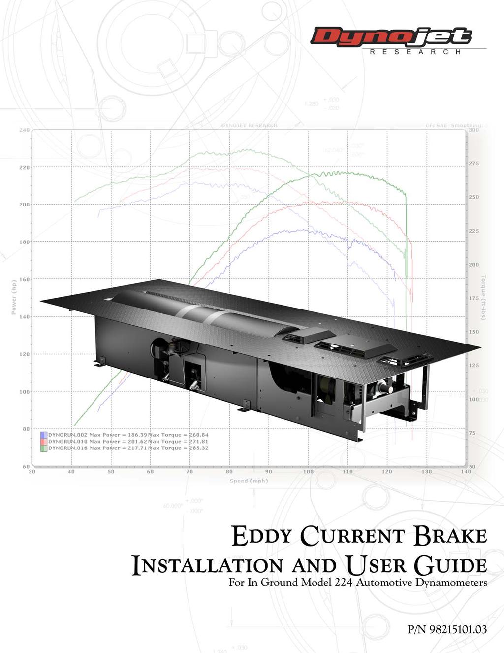
Eddy Current Brake Installation and User Guide For In Ground Model 224 Automotive Dynamometers.
|
|
|
- Olivia Fowler
- 5 years ago
- Views:
Transcription
1
2 Dynojet Research, Inc. All Rights Reserved. Eddy Current Brake Installation and User Guide For In Ground Model 224 Automotive Dynamometers. This manual is copyrighted by Dynojet Research, Inc., hereafter referred to as Dynojet, and all rights are reserved. This manual, and the software described in it, is furnished under license and may only be used or copied in accordance with the terms of such license. This manual is furnished for informational use only, is subject to change without notice, and should not be construed as a commitment by Dynojet. Dynojet assumes no responsibility or liability for any error or inaccuracies that may appear in this manual. Except as permitted by such license, no part of this manual may be reproduced, stored in a retrieval system, or transmitted, in any form or by any means, electronic, mechanical, recording, or otherwise, without the prior written permission of Dynojet. The Dynojet logo is a trademark of Dynojet Research, Inc. Any trademarks, trade names, service marks, or service names owned or registered by any other company and used in this guide are the property of their respective companies. Dynojet Research, Inc., 2191 Mendenhall Drive, North Las Vegas, Nevada 89081, USA. Printed in USA. Part Number: Version 3 (03/2008) RECORD # Dynamometer Number: Eddy Current Brake (Retarder) Number:
3 TABLE OF CONTENTS Warnings iii Eddy Current Brake Installation Introduction Conventions Used In This Manual Technical Support Dyno and Pit Preparation Removing the Pit Covers Verifying the Pit Dimensions Eddy Current Brake Installation Before Installing the Eddy Current Brake Verify Optimal Brake Cooling... 7 Unpacking the Eddy Current Brake Installing the Temperature Sensor Installing the Load Cell Installing the Bearing, Spline Shaft, and Driveline Assembly Installing the Eddy Current Brake Installing the Pit Cover Supports and Theta Controller Routing the Cables Wiring the Breakout Board Securing the Brake to the Pit Floor Torque Module Installation Installing the Torque Module Connecting the Load Cell Cable Installing the End Deck and Deck Assemblies Load Cell Calibration i
4 TABLE OF CONTENTS Appendix A Red Head Anchor Installation Warnings A-1 Contact Information for ITW Ramset/Red Head A-1 Installation A-2 Appendix B Power Requirements and Installation Power Requirements and Installation North America, Japan, and Locations Using 60 Hz Power B-2 Installing the Wall Receptacle B-2 Testing for Correct Voltages B-3 Hard Wiring to the Building B-4 Power Requirements and Installation Excluding North America and Japan B-5 Installing the Wall Receptacle B-6 Testing for Correct Voltages B-7 Hard Wiring to the Building B-7 Appendix C Installing the Adapter and Bearing Early Model Dynamometers Installing the Adapter and Bearing Early Model Dynos C-2 Appendix D Torque Values Standard Bolt Torque Values D-2 Grade D-2 Grade D-3 Metric Bolt Torque Values D-4 Grade D-4 Grade D-4 Index Index-i ii
5 WARNINGS Disclaimers Dynojet Research, Inc. (Dynojet) makes no representation or warranties with respect to the contents hereof and specifically disclaims any implied warranties of merchantability for any particular purpose. Dynojet reserves the right to revise this publication and to make changes from time to time in the content hereof without obligation of Dynojet to notify any person of such revision or changes. Dynojet is not responsible for false operation due to unexpected dynamometer operation such as may be caused by static, software bugs, hardware failure, etc. Dynojet is not responsible for damage resulting from improper installation of the dynamometer or from improper service rendered to the dynamometer. Dynojet is not responsible for damage incurred due to alteration of the dynamometer or components, use of unapproved parts, or abuse to the dynamometer. Do not connect or disconnect cables or components on the dynamometer with the power on. Always wear protective clothing, ear protection, and eye protection (goggles, safety glasses) when using and servicing the dynamometer. Equipment Power Requirements The dynamometer has specific power requirements. Connecting the dynamometer to the incorrect voltage will void the dynamometer warranty. Installation may require a licensed electrician. Potentially Lethal Voltages Components attached to and within the dynamometer operate with potentially lethal voltages. To provide the greatest assurance of safety, the AC power cord(s) must be disconnected from the power source before servicing electrical components or wiring. Disconnect all power cords before servicing electrical components for the greatest assurance of safety. iii
6 WARNINGS Electrostatic Discharge Precautions Electrostatic Discharge Electrostatic Discharge (ESD), or static shock, can damage electronic components within the dynamometer. The damage may occur at the time of an ESD occurrence, or the shock may degrade the component, resulting in a premature component failure later. To avoid ESD damage, always practice good ESD control precautions when servicing the dynamometer. Dynojet designs its dynamometers to be very tolerant of static shocks by the users, but the electronics are vulnerable when the electronics are exposed. ESD occurs as a result of a difference of potential between two objects when the two objects touch. Damage occurs as a result of the energy released when the discharge (touch) occurs. The difference of potential can accumulate by as simple an action as a user moving across carpet or a seat. If that person s energy is discharged directly to the electronics, the electronics can be damaged. Precautions To protect against ESD damage, you must eliminate the difference of potential before the electronics are handled. Touch the chassis of the dynamometer before touching any of the electronics. By touching the chassis, you discharge any static shocks to the chassis instead of to the electronics. If you are holding a circuit board or dynamometer component in your hand when you approach the machine, touch the chassis of the dynamometer with your hand before installing the circuit board or component. When handling a circuit board or component to someone, touch that person with your hand first, then hand them the component. Always carry circuit boards in anti-static bags when the boards are exposed (removed from the dynamometer). Battery Fire and Explosion Hazards There is a danger of explosion if the battery is incorrectly replaced. Replace only with the same or equivalent type recommended by the manufacturer. Discard used batteries according to the manufacturer s instructions. Automotive Batteries In operation, batteries generate and release flammable hydrogen gas. They must always be assumed to contain this gas which, if ignited by burning cigarette, naked flame or spark, may cause battery explosion with dispersion of casing fragments and corrosive liquid electrolyte. Carefully follow manufacturer's instructions for installation and service. Keep away all sources of gas ignition and do not allow metallic articles to simultaneously contact the negative and positive terminals of a battery. Do not allow the positive and negative terminals to short-circuit. The dynamometer chassis is tied to the negative side of the battery. Do not short between the positive battery terminal or the starter connections to the chassis. In addition, make sure metal tools such as screw drivers, wrenches, and torque wrenches do not come in contact with the negative and positive terminals of the battery. Short circuiting the terminals of the battery can cause burn injuries, damage to the dynamometer, or trigger explosions. Charging Batteries being charged will generate and release flammable hydrogen gas. Charging space should be ventilated. Keep battery vent caps in position. Prohibit smoking and avoid creation of flames and sparks nearby. Wear protective clothing, eye and face protection, when charging or handling batteries. iv
7 WARNINGS Other Potential Hazards The AC power outlet shall be installed near the equipment and it shall be easily accessible to allow for disconnect before service. The dynamometer should be located in a well ventilated area. There is a carbon monoxide hazard with all internal combustion engines. Engine exhaust contains poisonous carbon monoxide gas. Breathing it could cause death. Any dyno room design must incorporate sufficient exhaust extraction. Always wear proper ear and eye protection when operating the dynamometer. Never operate the dynamometer with the covers removed. Never stand behind the dynamometer when in operation. Never operate the dynamometer when there is excessive vibration or noise. Resolve these problems before proceeding. Never fuel the vehicle on the dynamometer unless appropriate safety measures are taken. Verify brake operation before beginning any dynamometer testing. Verify the vehicle is properly secured to the dynamometer. Never operate the blowers without the guards installed. Exercise care with any dynamometer testing; portions of the dynamometer and vehicle may become hot. As with any equipment using electricity and having moving parts, there are potential hazards. To use this dynamometer safely, the operator should become familiar with the instructions for operation of the dynamometer and always exercise care when using it. Do not repair or replace any part of the dynamometer or attempt any servicing unless specifically recommended in published user-repair instructions that you understand and have the skills to carry out. Version 3 v
8
9 This document provides instructions for installing the eddy current brake (retarder) to the Dynojet in ground model 224 automotive dynamometer (dyno). This document also provides instructions for installing and calibrating the load cell. To ensure safety and accuracy in the procedures, perform the procedures as they are described. Document Part Number: Version 3 Last Updated: This chapter is divided into the following categories: Introduction, page 2 Dyno and Pit Preparation, page 4 Eddy Current Brake Installation, page 7 Torque Module Installation, page 23 Load Cell Calibration, page 30 1
10 Introduction INTRODUCTION Before installing your eddy current brake, please take a moment to read this guide for installation instructions and other important information. This guide is designed to be a reference tool in your everyday work and includes the following chapters and information: EDDY CURRENT BRAKE INSTALLATION This chapter describes the procedures for installing the eddy current brake, torque module, and load cell. This chapter also includes the procedures for load cell calibration. RED HEAD INSTALLATION This appendix describes the procedures for installing the Red Head anchors. POWER REQUIREMENTS This appendix describes the power requirements and installation instructions for the eddy current brake. INSTALLING THE ADAPTER AND BEARING EARLY MODEL DYNOS This appendix describes the procedures for installing the adapter and bearing needed for early model dynos. TORQUE VALUES This appendix describes the standard and metric torque values. 2
11 Introduction CONVENTIONS USED IN THIS MANUAL The conventions used in this manual are designed to protect both the user and the equipment. example of convention Bold RECORD # description The Caution icon indicates a potential hazard to the dynamometer equipment. Follow all procedures exactly as they are described and use care when performing all procedures. The Warning icon indicates potential harm to the person performing a procedure and/or the dynamometer equipment. The Record # icon reminds you to record your dynamometer and/or eddy current brake (retarder) number on the inside cover of this manual. Highlights items you can select on in the software interface, including buttons and menus. The arrow indicates a menu choice. For example, select File Open means select the File menu, then select the Open choice on the File menu. TECHNICAL SUPPORT For assistance, please contact Dynojet Technical Support at , or write to Dynojet at 2191 Mendenhall Drive, North Las Vegas, NV Visit us on the World Wide Web at where Dynojet provides state of the art technical support, on-line shopping, 3D visualizations, and press releases about our latest product line. Version 3 3
12 Dyno and Pit Preparation DYNO AND PIT PREPARATION Before installing the eddy current brake, prepare the dyno and the pit as described in this section. REMOVING THE PIT COVERS Removing the pit covers will make the eddy current brake installation and access to the dyno easier. 1 Remove the seven screws securing each long pit cover and set aside. 2 Remove the long pit covers and set aside. long pit cover Figure 1: Remove the Long Pit Covers 4
13 Dyno and Pit Preparation 3 Remove the two screws securing the end pit cover and set aside. 4 Remove the end pit cover and set aside. end pit cover Figure 2: Remove the End Pit Cover Version 3 5
14 Dyno and Pit Preparation VERIFYING THE PIT DIMENSIONS Before installing your dynamometer, prepare your pit according to the specifications provided by your salesperson. Refer to the pit dimensions (P/N ) for more detailed specifications. description specifications length cm ( in.) length with eddy current brake cm ( in.) depth cm (23.00 in.) width cm (53.00 in.) cm (53.00 in.) cm ( in.) cm (23.00 in.) Figure 3: Verify the Pit Dimensions 6
15 Eddy Current Brake Installation EDDY CURRENT BRAKE INSTALLATION You will need to provide equipment capable of lifting the eddy current brake off the crate and into position in your dyno room. You will also need a pair of straps. Dynojet recommends using single loop style straps. To prevent possible injury, turn off the dyno electronics and unplug the dyno. BEFORE INSTALLING THE EDDY CURRENT BRAKE VERIFY OPTIMAL BRAKE COOLING Placing the eddy current brake on the left or right side of the dyno will determine the direction that it turns. For optimal eddy current brake cooling, the brake should turn in the direction of the arrows on the rotors. When running mostly rear wheel drive cars, orient the dyno and brake so the brake is turning in the direction of the arrows when a rear wheel drive car is on the dyno. Note: The dyno will function correctly for front wheel drive cars, but cooling of the rotors will not be optimal. Version 3 7
16 Eddy Current Brake Installation UNPACKING THE EDDY CURRENT BRAKE 1 Remove the top and sides of the crate. 2 Remove any hardware and parts boxes from the crate and verify the box contents. 3 Remove the uprights and cross members from the crate. crate top uprights and cross members remove boxes Figure 4: Remove the Crate Top 8
17 Eddy Current Brake Installation 4 Remove the two screws securing each pit cover support. Set the screws and supports aside. RECORD # Be sure you record the dynamometer and/or eddy current brake number on the inside cover of this manual. pit cover support pit cover support EB096 brake number Figure 5: Remove the Pit Cover Supports Version 3 9
18 Eddy Current Brake Installation INSTALLING THE TEMPERATURE SENSOR Use the following instructions to secure the temperature sensor to the eddy current brake in the location shown. You will need the following parts: Temperature Sensor Assembly Figure 6: Temperature Sensor Location temperature sensor 1 Remove the nut from the sensor. 2 Slide the sensor through the cross brace. 3 Secure the sensor to the brace using the nut removed earlier. Note: For clarity, the side panel has been removed. remove nut nut cross brace sensor Figure 7: Install the Temperature Sensor 10
19 Eddy Current Brake Installation INSTALLING THE LOAD CELL You will need the following part: Load Cell Assembly 1 Verify the main dyno power is disconnected. 2 Remove the two bolts and nuts securing the existing bar on the eddy current brake and remove the bar. Set the bolts and nuts aside. 3 Verify the eyelets on the load cell are spaced the same as the bar removed earlier. Adjust the load cell spacing by loosening the lock nut and turning the eyelet. bar eyelet lock nut distance must be the same Figure 8: Verify the Load Cell Spacing 4 Secure the load cell to the mounting bracket using the two bolts and nuts removed earlier. load cell cable dyno install the load cell (the brake is not shown for clarity) Figure 9: Install the Load Cell Version 3 11
20 Eddy Current Brake Installation INSTALLING THE BEARING, SPLINE SHAFT, AND DRIVELINE ASSEMBLY The eddy current brake can be installed on either side of your dyno, the installation instructions are the same. You will need the following parts: Spline Shaft Bearing Bolt, 1/2-13 x 1.5", Flange-Hex (2) Driveline Assembly 1 Install the bearing using two 1/2-13 x 1.5-inch flanged bolts. Leave the bolts loose. Note: If you are retrofitting an early model dyno which does not have the bearing mounting holes, refer to the instructions in Appendix C. bearing mounting holes bearing Figure 10: Install the Bearing 12
21 Eddy Current Brake Installation 2 Insert the spline shaft through the bearing and into the spline hub of drum. Note: Make sure the short spline end faces out. 3 Push the spline shaft in until the shoulder is flush with the bearing. 4 Torque the bearing mounting bolts to 57 foot-pounds. 5 Torque the two set screws on the bearing to 25 foot-pounds. 6 Remove the four bolts securing the u-joint to the keyed driveline yoke. Set these bolts aside; they will be used to secure the eddy current brake to the driveline assembly. 7 Separate the keyed yoke from the driveline assembly. You may need to use a screwdriver or pry bar to separate the u-joint from the yoke. 8 Place the driveline assembly on the spline shaft. bearing mounting bolts spline shaft shoulder remove four bolts, two on either side bearing set screws driveline assembly Figure 11: Install the Driveline Assembly Version 3 13
22 Eddy Current Brake Installation INSTALLING THE EDDY CURRENT BRAKE You will need the following parts: Washer, 3/8", Hardened, Flat (8) DM Bolt, 3/8-16 x 1", Hex (8) 1 Remove the four lag bolts securing the brake to the crate 2 Place the keyed yoke onto the eddy current brake shaft. shaft yoke bolt shaft Figure 12: Remove the Bolts Securing the Brake to the Crate and Install the Yoke 14
23 Eddy Current Brake Installation 3 Place one nylon loop strap around the brake shaft with the yoke. Keep the strap close to the bearing. 4 Place one nylon loop strap around the other side of the brake shaft. Keep the strap close to the bearing. Dynojet recommends using single loop style straps. 5 Place the nylon loop straps around the forklift forks. 6 Slide the forklift forks together until the straps angle inward. This will prevent the straps from slipping off the brake shaft. 7 Using the forklift, lift the eddy current brake from the crate and place the brake in the pit next to the dyno. straps yoke shaft Figure 13: Remove the Brake from the Crate Version 3 15
24 Eddy Current Brake Installation 8 Line up the eddy current brake yoke with the driveline assembly. 9 Slide the brake frame towards the dyno frame until they touch. Make sure the brake yoke is aligned with the driveline. 10 Secure the yoke to the driveline assembly using the four bolts removed earlier. Torque the bolts to 70 foot-pounds. 11 Secure the brake frame to the dyno using eight 3/8 x 1-inch bolts and eight 3/8-inch hardened flat washers. Not all of the bolts and washers are visible from this view. 12 Torque the brake yoke set screws to 25 foot-pounds. secure brake side to dyno using bolts and washers (not all visible) brake yoke secure brake side to dyno using bolts and washers (not all visible) Figure 14: Secure the Brake Frame to the Dyno 16
25 Eddy Current Brake Installation INSTALLING THE PIT COVER SUPPORTS AND THETA CONTROLLER You will need the following parts: Cable Routing Channel Screw, 8-32 x 3/8", Ph-Sems, Phil (4) Screw, 1/4-20 x 5/8", PH, Torx (2) Theta Controller 1 Loosely secure the pit cover supports to the frame using the two 1/4-20 x 3/4-inch button-head flange screws for each support removed earlier. Note: Do not tighten the screws. 2 Verify the pit cover supports are flush with the top of the pit floor before you tighten the screws. 2a Place a straight edge across the pit cover supports. 2b With the pit cover supports tight against the straight edge, tighten the screws. Note: You can use c-clamps to attach the upright to the straight edges to make this quicker. Tighten the c-clamps until the pit cover supports are flush with the pit floor. 2c Remove the straight edge. Note: For clarity, the pit is not shown. pit cover supports Figure 15: Install the Pit Cover Supports Version 3 17
26 Eddy Current Brake Installation 3 Install the Theta Controller using four 8-32 x 3/8-inch screws. 4 Install the cable routing channel using two 1/4-20 x 5/8-inch screws. cable routing channel theta controller Figure 16: Install the Theta Controller and Cable Routing Channel 18
27 Eddy Current Brake Installation ROUTING THE CABLES 1 Route the temperature sensor cable from the eddy current brake over to the Breakout board. For more information on wiring the Breakout board refer to page Route the pick-up card cable from the pick-up card over to the Breakout board. For more information on wiring the Breakout board refer to page Route the 25-pin cable from the Breakout board along the inside of the panel using the cable routing channel, through one of the PVC conduits in the pit, and to the dyno electronics. 4 Route the load cell cable through one of the PVC conduits in the pit (not used by the input power cable) and to the dyno electronics. Make sure the load cell cable is clear of any power cable or hot or rotating objects 5 Route the brake power cable from the eddy current brake through the pit cover support and over to the Theta Controller (underneath). 6 Route the input power cable from the Theta Controller through the pit cover support, through the PVC conduit in the pit (not used by any other cables), and to your power source. 7 Route the control cable from the Theta Controller to the Breakout board. For more information on wiring the Breakout board refer to page 20. breakout board pick-up card cable temperature sensor cable 25-pin cable load cell cable brake power cable control cable input power cable theta controller Figure 17: Route the Cables Version 3 19
28 Eddy Current Brake Installation WIRING THE BREAKOUT BOARD Refer to Figure 18 on page 21 for Breakout board location information. 1 Attach the temperature sensor cable to the Breakout board. The temperature sensor cable has five wires which connect to the wiring block labeled TEMP. This cable was routed to the Breakout board on page 19. Green wire connects to G1 White wire connects to W1 Black wire connects to B1 Red wire connects to R1 Ground (shield) wire connects to S1 2 Attach the control cable to the Breakout board. The control cable has five wires which connect to the wiring block labeled LOAD CONTROL. This cable was routed to the Breakout board on page 19. Black wire connects to V- Red wire connects to V+ White wire connects to O+ Green wire connects to O- Ground (shield) wire connects to SH 3 Attach the pick-up card cable to the Breakout board. The pick-up card cable has four wires which connect to the wiring block labeled DRUM 1. This cable was routed to the Breakout board on page 19. Red wire connects to R1 Black wire connects to B1 White wire connects to W1 Ground (shield) wire connects to S1 20
29 Eddy Current Brake Installation 4 Verify jumpers J1 and J2 are set for the eddy current brake as shown in Figure 18. The air brake will be activated when the dyno electronics power is turned off or when the red button on the pendant is lit. The eddy current brake is used for load control. pickup card cable control cable jumpers J1 and J2 temperature sensor cable 25-pin cable Figure 18: Wire the Breakout Board Version 3 21
30 Eddy Current Brake Installation SECURING THE BRAKE TO THE PIT FLOOR Dynojet recommends you secure your eddy current brake to the pit floor in your dyno room using concrete anchors. You will need the following parts: Mounting Foot (2) Nut, 1/2-13, Nylock, Hex (2) Bolt, 1/2-13 x 1.25", Flange, Hex (2) Washer, 3/8", Hardened, Flat, Steel (2) Anchor, Redhead, 3/8" (2) Redhead Anchor Installation Tool DM Bolt, 3/8-16 x 1", Hex (2) 1 Using the mounting feet as a template, mark and drill each hole needed to secure the two feet to the floor. 2 Install two Red Head anchors. Refer to Appendix A for installation instructions. 3 Secure one foot to the left and right panels using one 1/2-13 x 1.25-inch flange bolt and one 1/2-13-inch nylock nut (not visible) each. 4 Secure each mounting foot to the floor using one 3/8-16 x 1-inch hex bolt and one 3/8-inch flat washer. install red head anchor foot bolt (nut not visible) Figure 19: Secure the Brake to the Pit Floor 22
31 Torque Module Installation TORQUE MODULE INSTALLATION This section describes how to install the Torque Module(s), connect the load cell cable, and install the end deck and deck assemblies. INSTALLING THE TORQUE MODULE You will need the following part: Torque Module 1 Verify the main dyno power is disconnected. 2 Turn off the main power switch on the CPU Module and unplug the power cord. 3 Remove the dust cover from the existing top module. dust cover power cord input power switch HS039 Figure 20: Disconnect the Power and Remove the Dust Cover Version 3 23
32 Torque Module Installation 4 Loosen the top right screw on the back of the existing top module. 5 Plug the Torque Module (or modules) into the existing top module. Place the dust cover, removed in step 3, on the Torque Module. dust cover torque module TM054 Figure 21: Attach the Torque Module 24
33 Torque Module Installation 6 Secure the grounding strap on the back of the Torque Module to the existing top module. 7 Secure the Torque Module to the dyno electronics with the plastic tie straps (one on each side). Note: Do not attach the load cell cable at this time. grounding strap plastic tie strap HS040 Figure 22: Secure the Grounding Strap Version 3 25
34 Torque Module Installation CONNECTING THE LOAD CELL CABLE You will need the following part: Load Cell Cable 1 Route the load cell cable from the load cell, through the PVC conduit in the pit (not used by input power cable), and over to the dyno electronics. Make sure the load cell cable is clear of any power cables or hot or rotating objects. 2 Attach the 9-pin connector on the load cell cable to the front of the Torque Module and tighten down the screws. Note: When there are two Torque Modules, connect the load cell cable from the 4WD dyno to the top Torque Module. 3 Attach the power cord to the CPU Module and turn the power switch on. 4 The green LED light on the Torque Module(s) should now be on. green LED light torque modules attach load cell cable attach power cord TM055 turn on power Figure 23: Connect the Load Cell Cable 26
35 Torque Module Installation INSTALLING THE END DECK AND DECK ASSEMBLIES Before installing the end deck and deck assemblies, verify all cables have been routed. Refer to Routing the Cables on page 19 for more information. You will need the following parts: End Deck Assembly Deck Assembly Hood Scoop Hood Scoop, 20" Screw, 1/4-20 x 5/8", PH, Torx (8) Bolt, 3/8-16 x 1/2", Button-Head Flange (7) DM Nut, 1/4" (4) 1 If not already installed, secure each hood scoop to the deck assembly using four 1/4-20 x 5/8-inch pan-head torx screws and four 1/4-inch nuts each. 2 Loosely install the deck assembly to the pit supports using four 3/8-16 x 1/2-inch button-head flange screws. hood scoop deck assembly Figure 24: Install the Deck Assembly Version 3 27
36 Torque Module Installation 3 Loosely install the end deck assembly using three 3/8-16 x 1/2-inch button-head flange screws and the two screws removed earlier. end deck assembly Figure 25: Install the End Deck Assembly 28
37 Torque Module Installation 4 Install each long pit cover to the dyno using the seven screws removed earlier. 5 Tighten all deck screws. long pit cover Figure 26: Install the Long Pit Covers Version 3 29

38 Load Cell Calibration LOAD CELL CALIBRATION This section provides instructions for calibrating the load cell. Follow the directions on the screen exactly. Failure to perform the directions accurately will result in improper torque values. You will need the following parts: Weight (4) Calibration Arm Assembly 1 Verify you are in the MakeRun screen. 2 Verify you are connected to the dyno electronics. Note: For more information on connecting to the dyno electronics, refer to the WinPEP 7 User Guide (on your WinPEP CD or at or the WinPEP 7 Online Help. 3 Select Tools MakeRun Options Torque Cell Calibration. Note: Before proceeding, be sure the eddy current brake is free and clear of any obstructions. There should not be anything resting on the eddy current brake or the dynamometer drum during this procedure. 4 Click Next to perform the Zero Calibration. The Calibration window will appear. The hardware is now zeroing out the torque cell. If the unit does not calibrate, recheck the setup and retry. Figure 27: Zero Calibration Window 30
39 Load Cell Calibration Once the Zero Calibration is complete, the Calibration Mass window will appear. 5 Enter the Torque Module calibration value. Refer to Figure 29. Note: You must perform this step the first time you calibrate the load cell. Or If you are only performing a Zero Calibration, click Finish. Figure 28: Calibration Mass Window Enter the calibration number stamped near the bolt pattern at the end of the calibration arm. If you do not have enough room to use the bolt pattern closest to the end of the calibration arm, use the number stamped near the bolt pattern in the center of the arm. Note: Dynojet recommends you secure the calibration arm using the bolt pattern closest to the end of the arm unless space constraints in your dyno room do not allow you to. bolt pattern near the center of the calibration arm bolt pattern closest to the end of the calibration arm Figure 29: Calibration Arm Number Version 3 31

40 Load Cell Calibration 6 Click Next to continue. The Span Calibration window will appear. Figure 30: Span Calibration Window 7 Install the calibration arm and weights. Note: Calibration arm placement determines positive direction for torque. Place the weights towards the rear of the vehicle as shown in Figure 31 and Figure 32. Refer to step 8 and Figure 33 on page 34 for calibration arm installation instructions. place the weights towards the rear of the vehicle Figure 31: Calibration Arm Placement Front Wheel Drive 32

41 Load Cell Calibration place the weights towards the rear of the vehicle Figure 32: Calibration Arm Placement Rear Wheel Drive Version 3 33
42 Load Cell Calibration 8 Install the calibration arm and weights using the bolts at the end of the calibration arm. Note: If you do not have enough room to use the bolt pattern closest to the end of the calibration arm, use the bolt pattern in the center of the arm. Refer to Figure 34 on page 35. 8a Secure the calibration arm to the eddy current brake by tightening the bolt using the handle. 8b Gently place the weights on the calibration arm. Note: Verify the calibration arm is not contacting the cover. The calibration weights are very heavy. The weights must be set on the arm gently or you will damage the load cell. secure arm to brake by tightening handle weight support pin weights Figure 33: Install the Calibration Arm and Weights Using the Bolt Pattern Closest to the End 34
43 Load Cell Calibration If you do not have enough room to use the bolt pattern closest to the end of the calibration arm, use the bolt pattern in the center of the arm as shown in Figure 34. secure arm to brake by tightening handle weight support pin weights Figure 34: Install the Calibration Arm and Weights Using the Bolt Pattern in the Center Version 3 35
44 Load Cell Calibration While installing the calibration weights, you should notice the Torque Gauge on the DynoTrac Window moving from 0 to about 500 foot-pounds. Note: The Torque Gauge may or may not be in this range. If the torque cell has been previously calibrated incorrectly or has not been calibrated for a while, the gauge may show values out of this range until calibration is complete. If you use the bolt pattern in the center of the calibration arm, the gauge will show values around foot-pounds. Note: Let the torque gauge needle stabilize before clicking Next. 9 From the Span Calibration window (Figure 30), click Next to continue. At this point, the value on the gauge should match the value on the calibration arm. 10 Remove the calibration arm and weights and click Finish. For more information on loading a vehicle and basic dyno operation, refer to the In Ground Model 224 Automotive Dynamometer Installation and User Guide (P/N ). Figure 35: Calibration Is Complete Window 36
45 A PPENDIX A RED HEAD ANCHOR INSTALLATION This appendix contains instructions for installing the Red Head Multi-Set II Anchors. The anchors will be used to secure the dyno to concrete. To ensure safety and accuracy in the procedures, perform the procedures as they are described. Be sure to read and understand the warnings included in this appendix. WARNINGS Always wear safety glasses and other necessary protective devices or apparel when installing or working with anchors. ITW Ramset/Red Head Multi-Set II Anchors are designed to operate properly only when installed with ITW Ramset/Red Head brand Setting Tools. The use of a 24 to 40 ounce hammer is recommended for expanding Multi-Set II anchors. The use of carbide drill bits manufactured with ANSI B drill bit diameter requirements is recommended for installation of this anchor. Not recommended for use in lightweight masonry material such as block or brick. Use of core drills is not recommended to drill holes for use with this anchor. Not recommended for use in new concrete which has not had sufficient time to cure. Anchor spacing and edge distance requirements (anchor installation locations) are the responsibility of the engineer of record. CONTACT INFORMATION FOR ITW RAMSET/RED HEAD Contact ITW Ramset/Red Head at , or 1300 North Michael Drive, Wood Dale, IL A-1
46 APPENDIX A Installation INSTALLATION Use the table below to determine the catalog number, drill bit size, minimum hole depth, and setting tool catalog number. catalog number drill bit size minimum hole depth setting tool catalog number Carbon Steel RM-38/RL-38 (9.5 mm) 1/2-inch 1 5/8-inch (41.2 mm) RT-138 Use the following instructions to install the Red Head anchors. 1 Drill the hole in the concrete the same outside diameter as the anchor being used to any depth exceeding minimum embedment. 2 Insert the anchor. Figure A-1: Red Head Anchor Drill the Hole anchor Figure A-2: Red Head Anchor Insert the Anchor A-2
47 RED HEAD ANCHOR INSTALLATION Installation 3 Using a hammer, drive the anchor flush with the surface of the concrete, or below the surface if the hole depth exceeds minimum embedment. Figure A-3: Red Head Anchor Drive the Anchor Flush 4 Using a hammer, expand the anchor with the setting tool. The anchor is properly expanded when the shoulder of the setting tool is flush with the top of the anchor. Note: Use only Ramset/Red Head setting tools to insure proper installtion. setting tool Figure A-4: Red Head Anchor Expand the Anchor Version 3 A-3
48
49 A PPENDIX B POWER REQUIREMENTS AND INSTALLATION This appendix contains power requirements and installation instructions for the eddy current brake. To ensure safety and accuracy in the procedures, perform the procedures as they are described. Be sure to read and understand the warnings included in this appendix. This Appendix is divided into the following categories: North America, Japan, and Locations Using 60 Hz Power, on page B-2 Excluding North America and Japan, on page B-5 B-1
50 APPENDIX B Power Requirements and Installation North America, Japan, and Locations Using 60 Hz Power POWER REQUIREMENTS AND INSTALLATION NORTH AMERICA, JAPAN, AND LOCATIONS USING 60 HZ POWER The following power requirements and instructions are for North America, Japan, and locations using 60 Hz power. Refer to Power Requirements and Installation Excluding North America and Japan on page B-5 for all other locations. The eddy current brake requires a dedicated 240VAC single-phase power outlet rated for 30A for proper operation. Failure to follow these instructions could result in personal injury or damage to the brake. Connecting the brake to the incorrect voltage will void the warranty. Contact Dynojet with any questions. Each eddy current brake requires a dedicated wall receptacle which must be wired for operation and is included with the brake or may be shipped in advanced in a separate package. The brake is equipped with a twenty-five foot power cord with a twist lock plug pre-wired on the end. The dedicated wall receptacle is a twist lock four wire grounded 30A NEMA L14-30 type and must be wired in accordance with local building codes and requirements. If the facility does not have 120/240 volt single-phase power, and it does have 120/208 volt three-phase Y power, then it is acceptable to connect the four wire receptacle with two of the three-phase lines, the neutral and the ground. With this arrangement, there will only be 208 volts between line 1 and line 2 instead of 240 volts. This acceptable, but performance of the eddy current brake will be reduced. In no case shall all three-phase lines be connected to the receptacle! Installation may require a licensed electrician and must conform to UL and NEC safety standards. Note: If you are installing your brake in North American or Japan and the brake is not equipped with twist lock four wire grounded plug, contact Dynojet before attempting to connect the brake. Local and national electrical codes require a grounded receptacle box. This circuit should have a dedicated 30A double pole circuit breaker. The brake should be the only device connected to this circuit. INSTALLING THE WALL RECEPTACLE The wall receptacle is included with your brake and is shipped in a separate box or may be shipped in advance in a separate package. The wall receptacle is a single-phase 240 volt 30A dedicated circuit with a neutral wire. The neutral wire is not used by the brake, but needs to be connected to terminal W. The cable carrying the power to this receptacle should be ten gauge or larger. Check with local building codes for the correct size. 1 Connect one of the 240V legs to the X terminal (gold colored screw). 2 Connect the other 240V leg to the Y terminal (gold colored screw). 3 Connect the neutral conductor to the W or WH terminal (silver screw). 4 Connect the ground conductor to the G terminal (green colored screw). B-2
51 POWER REQUIREMENTS AND INSTALLATION Power Requirements and Installation North America, Japan, and Locations Using 60 Hz Power TESTING FOR CORRECT VOLTAGES You must test the receptacle for proper voltages before the eddy current brake is connected to the outlet. If the voltage readings do not match the following table, DO NOT connect the brake. You must have a licensed electrician correct the power connection. Connecting the brake to the incorrect voltage can result in damage to the brake and will void the brake warranty. Contact Dynojet with any questions. Using a voltmeter that is capable of measuring AC voltage, measure between the points listed below and verify that the correct voltages are present. probe 1 probe 2 desired voltage measurement V to 260V* V to 130V V to 130V 3 box <5V *If using two of the three-phase lines of a 120/208 V 3 phase Y system, then expect to see 187V to 225V. 3 (G) 2 (Y) 4 (X) 1 (W) Figure B-1: Dedicated Power Receptacle Version 3 B-3
52 APPENDIX B Power Requirements and Installation North America, Japan, and Locations Using 60 Hz Power HARD WIRING TO THE BUILDING Use the following instructions to wire the brake directly to the building. The brake must connect to a two pole disconnect switch to allow the removal of all power to the brake for servicing. This box may contain fusing, circuit breakers, or the circuit protection may be upstream in the building power system. The circuit must be protected to 30A with slow blow fuses or time delayed circuit breakers. The power cord that attaches to the brake has three conductors internally and their colors are white, black, and green. 1 Remove the brake power plug and connect 240VAC single-phase between the black and the white wires through the disconnect switch. 2 Connect the green wire to the ground connection. 3 Refer to the previous table for testing and probe the new connections as follows: white wire as location #2 black wire as location #4 green wire as location #3 B-4
53 POWER REQUIREMENTS AND INSTALLATION Power Requirements and Installation Excluding North America and Japan POWER REQUIREMENTS AND INSTALLATION EXCLUDING NORTH AMERICA AND JAPAN The eddy current brake (excluding North America and Japan) requires a dedicated wall receptacle which must be wired for operation and is included with the brake or may be shipped in advanced in a separate package. The brake is equipped with a twenty-five foot power cord with a twist lock plug pre-wired on the end. The brake requires a dedicated 240VAC single-phase power outlet rated for 30A for proper operation. Failure to follow these instructions could result in personal injury or damage to the brake. Connecting the brake to the incorrect voltage will void the brake warranty. Contact Dynojet with any questions. The dedicated wall receptacle is a three-pin IEC grounded 30A type and must be wired in accordance with local building codes and requirements. Installation may require a licensed electrician to conform to applicable safety standards. If you are installing your brake in a location other than North America or Japan and the brake is not equipped with a three pin IEC grounded plug, contact Dynojet before attempting to connect the brake. Local and national electrical codes will require that the box containing the receptacle is grounded. This circuit should have a dedicated 30A double-pole circuit breaker. The brake should be the only device connected to this circuit. Version 3 B-5
54 APPENDIX B Power Requirements and Installation Excluding North America and Japan INSTALLING THE WALL RECEPTACLE The wall receptacle is a single 240 volt 30A dedicated circuit with a ground. Note: The actual wall receptacle may be different from the image shown in Figure B-2; however, the installation instructions are the same. The cable carrying the power to this receptacle should be 4.0 mm 2 (ten gauge) or larger. Check with local building codes for the correct size. 1 Connect one of the 240V legs to the N terminal (no color). 2 Connect the other 240V leg to the L terminal (no color). 3 Connect the ground conductor to the green terminal. L terminal N terminal ground terminal (green) Figure B-2: Wiring the Wall Receptacle B-6
55 POWER REQUIREMENTS AND INSTALLATION Power Requirements and Installation Excluding North America and Japan TESTING FOR CORRECT VOLTAGES You must test the receptacle for proper voltages before the eddy current brake is connected to the outlet. Using a voltmeter that is capable of measuring AC voltage, measure between the points listed below and verify that the correct voltages are present. probe 1 probe 2 desired voltage measurement V to 250V 2 box <5V 3 (L) 1 2 (ground) Figure B-3: Testing the Wall Receptacle HARD WIRING TO THE BUILDING Use the following instructions to wire the brake directly to the building. The brake must connect to a two pole disconnect switch to allow the removal of all power to the brake for servicing. This box may contain fusing, circuit breakers, or the circuit protection may be upstream in the building power system. The circuit must be protected to 30A with slow blow fuses or time delayed circuit breakers. The power cord that attaches to the brake has three conductors internally and their colors are white, black, and green. 1 Remove the brake power plug and connect 240VAC single-phase between the black and the white wires through the disconnect switch. 2 Connect the green wire to the ground connection. 3 Refer to the previous table for testing and probe the new connections as follows: white wire as location #1 black wire as location #3 green wire as location #2 Version 3 B-7
56
57 A PPENDIX C INSTALLING THE ADAPTER AND BEARING EARLY MODEL DYNAMOMETERS This appendix contains instructions for installing the adapter and bearing on early model dynamometers (dynos); this includes dynos with serial numbers between and To ensure safety and accuracy in the procedures, perform the procedures as they are described. C-1
58 APPENDIX C Installing the Adapter and Bearing Early Model Dynos INSTALLING THE ADAPTER AND BEARING EARLY MODEL DYNOS Dynos missing the bearing mounting holes, shown in Figure 10 on page 12, will need to use the adapter (P/N ) to install the bearing. This includes dynos with serial numbers between and Orient the bearing to the adapter as shown in Figure C-1. The arrow on the adapter plate must point up. 2 Secure the bearing to the adapter plate using two 1/2-13 x 1.25-inch flange bolts and two 1/2-13-inch nuts. Leave the bolts loose. Note: The bolts are included with the eddy current brake while the nuts are included with the adapter kit. bearing adapter plate arrow Figure C-1: Early Model Dynos Install Bearing to Adapter 3 Secure the adapter plate to the dyno using six 1/2-13 x 3/4-inch bolts. bolt adapter plate Figure C-2: Early Model Dynos Install Adapter Plate C-2
59 INSTALLING THE ADAPTER AND BEARING EARLY MODEL DYNAMOMETERS Installing the Adapter and Bearing Early Model Dynos 4 Using the template included in this appendix, drill four additional holes into the dyno frame as shown. Note: If you needed to use the adapter plate, you will need to drill brake mounting holes in the dyno frame. 4a 4b Line the template up with the existing hole on the dyno. Drill two 3/8-16-inch UNC holes on each side of the dyno. template template drill holes drill holes existing hole existing hole Figure C-3: Early Model Dynos Using the Template Version 3 C-3
60
61 Template Placement Early Model Dynos ADD 3/8-16 UNC HOLES EXISTING HOLES DYNO FRAME END ADD 3/8-16 UNC HOLES 5 3/4" 5 3/4" EXISTING HOLES 1 5/8" Template Early Model Dynos Template Early Model Dynos UP ø 5/16" EXISTING HOLE 5 3/4" 5 3/4"
62 A PPENDIX D TORQUE VALUES This appendix contains tables for standard and metric torque values. Use these values when specified values are not given in other sections of this manual. D-1
63 APPENDIX D Standard Bolt Torque Values STANDARD BOLT TORQUE VALUES Always use the torque values specified in other sections of this manual. When specific values are not available, use the torque values listed below. Use the following guidelines when tightening torque: These values are based on use of clean, dry threads. The following tables include values for plain finish and plated fasteners. Reduce torque by 10% when engine oil is used as a lubricant. GRADE 5 The following tables are meant to be used as guidelines for Dynojet product torque values only. Always use caution when torquing fasteners. size torque, plain torque, plated in-threads/in in lb ft lb N m in lb ft lb N m 1/ / / / / / / / / / / / / / / / / / D-2
64 TORQUE VALUES Standard Bolt Torque Values GRADE 8 size torque, plain torque, plated in-threads/in in lb ft lb N m in lb ft lb N m 1/ / / / / / / / / / / / / / / / / / Version 3 D-3
65 APPENDIX D Metric Bolt Torque Values METRIC BOLT TORQUE VALUES Always use the torque values specified in other sections of this manual. When specific values are not available, use the torque values listed below. Use the following guidelines when tightening torque: These values are based on use of clean, dry threads. The following tables include values for plain finish and plated fasteners. Reduce torque by 10% when engine oil is used as a lubricant. GRADE 8.8 GRADE 10.9 The following tables are meant to be used as guidelines for Dynojet product torque values only. Always use caution when torquing fasteners. size torque, plain torque, plated mm x pitch in lb ft lb N m in lb ft lb N m M6 X M8 X M10 X M12 X M14 X M16 X M20 X M24 X size torque, plain torque, plated mm x pitch in lb ft lb N m in lb ft lb N m M6 X M8 X M10 X M12 X M14 X M16 X M20 X M24 X D-4

66 INDEX 25-pin cable, routing 1-19 A adapter plate C-2 B battery hazards iv bearing 1-12 retrofit C-2 brake power cable 1-19 breakout board control cable 1-20 jumpers 1-21 pick-up card cable 1-20 temperature sensor cable 1-20 wiring 1-20 C cable routing channels 1-18 calibration arm 1-31 number 1-31 placement 1-32 weights 1-34 control cable routing 1-19 wiring 1-20 conventions 1-3 D deck assembly 1-27 disclaimers iii document part number 1-1 E eddy current brake load cell 1-11 optimal cooling 1-7 securing to floor 1-22 temperature sensor 1-10 torque module 1-23 unpacking 1-8 wiring breakout board 1-20 electrostatic discharge iv end deck assembly 1-28 ESD precautions iv G grade 10.9 torque values D-4 grade 5 torque values D-2 grade 8 torque values D-3 grade 8.8 torque values D-4 H hazards v I input power cable 1-19 K keyed yoke 1-13, 1-14 L load cell calibrating 1-30 installing 1-11 routing the cable 1-19, 1-26 load cell calibration calibration arm 1-31 calibration number 1-31 calibration weights 1-34 Index-i
Eddy Current Brake Installation and User Guide For Model 224 Above Ground Automotive Dynamometers.
 2004-2008 Dynojet Research, Inc. All Rights Reserved. Eddy Current Brake Installation and User Guide For Model 224 Above Ground Automotive Dynamometers. This manual is copyrighted by Dynojet Research,
Torque Module Installation and User Guide for model 250i Motorcycle Dynamometers.
 2000-2005 Dynojet Research, Inc. All Rights Reserved. Torque Module Installation and User Guide for model 250i Motorcycle Dynamometers. This manual is copyrighted by Dynojet Research, Inc., hereafter referred
Eddy Current Brake Installation and User Guide For Model 224 Pit Automotive Dynamometers.
 2004-2005 Dynojet Research, Inc. All Rights Reserved. Eddy Current Brake Installation and User Guide For Model 224 Pit Automotive Dynamometers. This manual is copyrighted by Dynojet Research, Inc., hereafter
Torque Cell Installation Guide for Model 250i/250iP DynoWare RT Dynamometers.
 2015 Dynojet Research, Inc. All Rights Reserved. Torque Cell Installation Guide for Model 250i/250iP DynoWare RT Dynamometers. This manual is copyrighted by Dynojet Research, Inc., hereafter referred to
Harley-Davidson and the Bar & Shield logo are among the trademarks of H-D Michigan, LLC.
 2010-2012 Dynojet Research, Inc. All Rights Reserved. Harley-Davidson JUMPSTART Intallation and User Guide This manual is copyrighted by Dynojet Research, Inc., hereafter referred to as Dynojet, and all
Installation Guide for In Ground Model 224 Automotive Dynamometers.
 2014-2015 Dynojet Research, Inc. All Rights Reserved. Installation Guide for In Ground Model 224 Automotive Dynamometers. This manual is copyrighted by Dynojet Research, Inc., hereafter referred to as
Linx System with Atra Flex Installation for Model 424 Automotive Dynamometers
 2009-2018 Dynojet Research, Inc. All Rights Reserved. Linx System with Atra Flex Installation for Model 424 Automotive Dynamometers This manual is copyrighted by Dynojet Research, Inc., hereafter referred
Installation Guide for Above Ground Model 224 Automotive Dynamometers.
 2005-2014 Dynojet Research, Inc. All Rights Reserved. Installation Guide for Above Ground Model 224 Automotive Dynamometers. This manual is copyrighted by Dynojet Research, Inc., hereafter referred to
Air Fuel Ratio Module and AFR-4 Pump Assembly Installation and User Guide.
 2007-2012 Dynojet Research, Inc. All Rights Reserved.. This manual is copyrighted by Dynojet Research, Inc., hereafter referred to as Dynojet, and all rights are reserved. This manual, as well as the software
Dynojet Research, Inc. All Rights Reserved. Air Fuel Ratio Module Installation and User Guide.
 2014-2015 Dynojet Research, Inc. All Rights Reserved.. This manual is copyrighted by Dynojet Research, Inc., hereafter referred to as Dynojet, and all rights are reserved. This manual, as well as the software
Control Panel Interface Upgrade Installation Guide For Model 200i and 250i Motorcycle Dynamometers Serial Number 202xxxx.
 2004 Dynojet Research, Inc. All Rights Reserved. Control Panel Interface Upgrade Installation Guide For Model 200i and 250i Motorcycle Dynamometers Serial Number 202xxxx. This manual is copyrighted by
2006 Dynojet Research, Inc. All Rights Reserved. Spring Applied Air Release (SAAR) Brake Assembly Installation
 Brake Assembly Installation") 2006 Dynojet Research, Inc. All Rights Reserved. This manual is copyrighted by Dynojet Research, Inc., hereafter referred to as Dynojet, and all rights are reserved. This manual, as well as the software
2006 Dynojet Research, Inc. All Rights Reserved. This manual is copyrighted by Dynojet Research, Inc., hereafter referred to as Dynojet, and all rights are reserved. This manual, as well as the software
Dynojet Research, Inc. All Rights Reserved. Optical RPM Sensor Installation Guide.
 1993-2001 Dynojet Research, Inc. All Rights Reserved.. This manual is copyrighted by Dynojet Research, Inc., hereafter referred to as Dynojet, and all rights are reserved. This manual, as well as the software
Power Carriage Installation Guide
 Power Carriage Installation Guide 1999-2002 Dynojet Research, Inc. All Rights Reserved. 020116SD Dynojet Research, Inc. 200 Arden Drive Belgrade, MT 59714 2191 Mendenhall Drive North Las Vegas, NV 89031
Dynojet Research, Inc. All Rights Reserved. Tire Temperature Sensor Installation Guide
 1998-2006 Dynojet Research, Inc. All Rights Reserved. This manual is copyrighted by Dynojet Research, Inc., hereafter referred to as Dynojet, and all rights are reserved. This manual, as well as the software
Maintenance Guide For Model 224, Model 224 with 4WD, Model 424x, and Model 248 Automotive Dynamometers.
 2004-2008 Dynojet Research, Inc. All Rights Reserved. Maintenance Guide For Model 224, Model 224 with 4WD, Model 424x, and Model 248 Automotive Dynamometers. This manual is copyrighted by Dynojet Research,
Dynojet Research, Inc. All Rights Reserved. Installation Guide For the Kart and ATV Dynamometers.
 1993-2005 Dynojet Research, Inc. All Rights Reserved. Installation Guide For the Kart and ATV Dynamometers. This manual is copyrighted by Dynojet Research, Inc., hereafter referred to as Dynojet, and all
Electric Vehicle Charging Station
 EVoReel Electric Vehicle Charging Station INSTALLATION GUIDE AND USER MANUAL Model: Dual Output Pedestal Mount 30A EVoReel EVSE Model Numbers: With Basic EVSE: EV072-400-002A; With Intelligent ievse: EV072-410-002A;
INSTALLATION GUIDE AND USER MANUAL
 Electric Vehicle Charging Station INSTALLATION GUIDE AND USER MANUAL Model: 30A EVoCharge EVSE Model Number: EV072-300-001A Product Safety Certification: UL and cul Listed Description: SAE J1772 AC Level
INSTALLATION GUIDE AND USER MANUAL
 Electric Vehicle Charging Station INSTALLATION GUIDE AND USER MANUAL SAE J1772 AC Level 2 EVSE Model: 30A EVoCharge EVSE Wall Mount P/N: EV072-300-001A Version 2.0 IMPORTANT Read this manual thoroughly
Motorcycle Dynamometer Installation Guide
 Motorcycle Dynamometer Installation Guide 1993-2002 Dynojet Research, Inc. All Rights Reserved. 020329SD Dynojet Research, Inc. 200 Arden Drive Belgrade, MT 59714 2191 Mendenhall Drive North Las Vegas,
Revision A
 Remanufactured 82-90XL Pinspotter Safety Guard Kit Installation Manual 400-082-001 Revision A 82-90XL Pinspotter Safety Guard Kit Installation Manual, 400-082-001, Rev. A Summary of Changes Change No.
INSTALLATION MANUAL ELECTRIC DOUBLE OVEN RANGE
 ENGLISH ESPAÑOL INSTALLATION MANUAL ELECTRIC DOUBLE OVEN RANGE Please read these instructions thoroughly before installing and operating the range. LDE3019ST LDE3017ST LDE3017SB LDE3017SW LDE3015ST LDE3015SB
Installation Instructions Studio Makeup Station
 Installation Instructions Studio Makeup Station 30" and 36" Models 5-light 30" Studio Makeup Station 8-light 30" Studio Makeup Station 6-light 36" Studio Makeup Station 9-light 36" Studio Makeup Station
MODEL A96 SERIES. 130Vdc Switchmode Utility Rectifier / Battery Charger. Used with LaMarche Power Cage ECN/DATE
 MODEL A96 SERIES 130Vdc Switchmode Utility Rectifier / Battery Charger Used with LaMarche Power Cage CPN112138 ECN/DATE ISSUE DATE: ECN 17010-12/05 106 BRADROCK DRIVE DES PLAINES, IL. 60018-1967 (847)
Installation Guide For Model 248 Four Post Lift Automotive Dynamometers.
 1993-2005 Dynojet Research, Inc. All Rights Reserved. Installation Guide For Model 248 Four Post Lift Automotive Dynamometers. This manual is copyrighted by Dynojet Research, Inc., hereafter referred to
MASTERsine Inverter PXA Series Installation Guide
 Backup Power System Expert TM MASTERsine Inverter PXA Series Installation Guide Important Safety Instructions IMPORTANT: Read and save this Installation Guide for future reference. This chapter contains
Compressor Duty Motor - 1 HP. Model 40132
 Compressor Duty Motor - 1 HP Model 40132 Assembly and Operating Instructions 3491 Mission Oaks Blvd., Camarillo, CA 93011 Visit our web site at http://www.harborfreight.com Copyright 2002 by Harbor Freight
Installation Manual. For. High Speed Alumavator and Platinum. 10 and 23 Degree. Elevator Boat Lifts
 Installation Manual For High Speed Alumavator and Platinum 10 and 23 Degree Elevator Boat Lifts Page 2 Safety Precautions 1. Your boat lift is a heavy duty piece of equipment. It is important that all
Installation and Service Manual
 RESIDENTIAL PLATFORM LIFTS RPL400 / RPL600 Installation and Service Manual WARNING! STRICT ADHERENCE TO THESE INSTALLATION INSTRUCTIONS IS REQUIRED to promote the safety of those installing this product,
Installation Manual. For. Alumavator and Platinum. Vertical Installation. Elevator Boat Lifts
 Installation Manual For Alumavator and Platinum Vertical Installation Elevator Boat Lifts Page 2 Safety Precautions 1. Your boat lift is a heavy duty piece of equipment. It is important that all persons
MODEL A97 SERIES. Switchmode Utility Rectifier/Battery Charger ECN/DATE
 MODEL A97 SERIES Switchmode Utility Rectifier/Battery Charger CPN108172 ISSUE DATE: 16071 7/03 ECN/DATE 106 BRADROCK DRIVE DES PLAINES, IL. 60018-1967 (847) 299-1188 FAX: (847)299-3061 Page 1 of 7 INSTRUCTION
INSTRUCTION MANUAL FOR PC63 CAGE
 INSTRUCTION MANUAL FOR PC63 CAGE CPN106833 ISSUE DATE: 15689-12/02 ECN/DATE 106 BRADROCK DRIVE DES PLAINES, IL. 60018 (847) 299-1188 FAX: (847) 299-3061 16816-6/05 INSTRUCTION DRAWING NUMBER: P25-LPC63-1
A48 / A48B (base plate) BATTERY CHARGER
 BATTERY CHARGER") A48 / A48B (base plate) BATTERY CHARGER CPN41054 ISSUE DATE: 12315-8/98 ECN/DATE 106 BRADROCK DRIVE DES PLAINES, IL. 60018-1967 (847) 299-1188 FAX: (847)299-3061 15349-07-07/02 16041 6/03 14575-2/01 INSTRUCTION
A48 / A48B (base plate) BATTERY CHARGER CPN41054 ISSUE DATE: 12315-8/98 ECN/DATE 106 BRADROCK DRIVE DES PLAINES, IL. 60018-1967 (847) 299-1188 FAX: (847)299-3061 15349-07-07/02 16041 6/03 14575-2/01 INSTRUCTION
Dual-Lite Trident TRF 40 Wide Battery Cabinet 20-40kVA Systems USER MANUAL
 Dual-Lite Trident TRF 40 Wide Battery Cabinet 20-40kVA Systems USER MANUAL 755-00020-DL 5/17/2017 2 755-00020-OEM R01 TABLE OF CONTENTS 1. Important Information About This Manual... 4 1.1 Manual Symbols...
MODEL ELC-12/40-CVM-D BATTERY CHARGER
 NATIONAL RAILWAY SUPPLY MODEL ELC-12/40-CVM-D BATTERY CHARGER Installing, Operating and Service Instructions for the ELC-12/40-CVM-D Solid State Charger PLEASE SAVE THESE IMPORTANT SAFETY AND OPERATING
ELECTRIC START KIT KIT P/N
 ELECTRIC START KIT KIT P/N 2873876 Application 2002 Polaris EDGE Models with 500-600 Domestic Engines Before you begin, read these instructions and check to be sure all parts and tools are accounted for.
Installation Instructions for Remote Mount HMI 211 Display Panel Kit A045J206
 Instruction Sheet 7-2013 Installation Instructions for Remote Mount HMI 211 Display Panel Kit A045J206 1 Introduction The information contained within is based on information available at the time of going
INSTALLATION GUIDE. Dynojet Research 2191 Mendenhall Drive Suite 105, North Las Vegas NV,
 INSTALLATION GUIDE www.dynojetwb2.com Dynojet Research 2191 Mendenhall Drive Suite 105, North Las Vegas NV, 89081 1-800-992-4993 2008 Dynojet Research, Inc. All Rights Reserved. Wideband 2 Installation
LESTRONIC II BATTERY CHARGER MODEL 07210
 LESTRONIC II BATTERY CHARGER MODEL 07210 PLEASE SAVE THESE IMPORTANT SAFETY AND OPERATING INSTRUCTIONS For correct operation of the equipment, it is important to read and be familiar with this entire manual
Installation Instructions
 SLP GM/Chevrolet LS3 COIL COVER KIT 2010+ Camaro 5.3L/6.2L 2007+ GMT900 5.3L/6.2L PN: 620038 Installation Instructions Important Notes: Before installing your SLP Coil Cover Kit, please read the installation
Raritan PX. Power Cord Installation Guide. Safety Guidelines. Safety Instructions
 QS Rule Raritan PX Power Cord Installation Guide This installation guide explains how to install power cords on Raritan PX products that do not come with a factory installed power cord. This type of product,
Model Description Vac. Max rating Pedestal Only: 36 Utility Pedestal W/O Disconnect General Duty Series:
 MAPA Products MPD-XX / Pedestal Disconnect 30, 60, 100 amp February 2014 Pedestal Disconnect Installation Instructions Parts List MAPA Products Fusible Rainproof Pedestal Mounted Safety Switch provides
xtablet T7000 Vehicle Mount Kit
 xtablet T7000 Vehicle Mount Kit Installation & Users Guide Last Updated: January 19, 2012 Find the latest updates in the Support section in the MobileDemand website at: www.ruggedtabletpc.com. Questions?
EVO TM 200 AND EVO TM 400 LCD DISPLAY INSTALLATION GUIDE
 EVO TM 200 AND EVO TM 400 LCD DISPLAY INSTALLATION GUIDE The information in this publication is provided for reference only. While every effort has been made to ensure the reliability and accuracy of the
LESTRONIC II BATTERY CHARGER BUILT-IN OR PORTABLE CHARGERS
 LESTRONIC II BATTERY CHARGER BUILT-IN OR PORTABLE CHARGERS PLEASE SAVE THESE IMPORTANT SAFETY AND OPERATING INSTRUCTIONS For correct operation of the equipment, it is important to read and be familiar
Installation Instructions. PowerFlex 700 Drive - Frame 8 Components Replacement
 Installation Instructions PowerFlex 700 Drive - Frame 8 Components Replacement Important User Information Solid-state equipment has operational characteristics differing from those of electromechanical
INSTALLATION AND OPERATING INSTRUCTIONS
 INSTALLATION AND OPERATING INSTRUCTIONS MANUAL TRANSFER SWITCHES FROM 0 Residential Wattage Requirements Appliance Running Watts Add watts for starting Furnace blower, gas or fuel 1/8 hp 300 500 1/8 hp
Assembly & Installation Instructions
 TM P R O D U C T S Assembly & Installation Instructions FOR 28 SERIES SNOWPLOW PIVOT ASSEMBLY AND FLOAT LIMITER 99103000 FOR SERIAL NUMBERS 28D100000 TO 28D100770 97100552A 1. THINK SAFETY, ALWAYS WEAR
P RO W ALL V ENTILATION H OODS INSTALLATION INSTRUCTIONS
 P RO W ALL V ENTILATION H OODS INSTALLATION INSTRUCTIONS CONTACT INFORMATION Wolf Customer Service: 800-332-9513 Website: wolfappliance.com As you follow these instructions, you will notice WARNING and
OnBoard Drum Major Podium
 Assembly and Owner s Manual OnBoard Drum Major Podium CONTENTS CONTENTS................................................................................. 1 SAFETY...................................................................................
801 BUSINESS CENTER DRIVE MOUNT PROSPECT, ILLINOIS Ext. 322
 277-999 ELECTRIC CORP. 801 BUSINESS CENTER DRIVE MOUNT PROSPECT, ILLINOIS 800-621-5485 Ext. 322 Send Warranty Product Repairs to: 605 South Vermilion, Suite C, Brownsville, TX 78521-6851 Call Customer
801 BUSINESS CENTER DRIVE MOUNT PROSPECT, ILLINOIS
 280-600 Send Warranty Product Repairs to: 1025 E. Thompson Ave., Hoopeston, IL 60942-0280. Call Customer Service if you have questions: 1-800-621-5485 A. IMPORTANT SAFETY INSTRUCTIONS 1. SAVE THESE INSTRUCTIONS
American Safe Room, Inc. Installation and Operation Manual for the ASR-101-BV 7-Bar Double Acting Automatic Blast Valve
 American Safe Room, Inc. Installation and Operation Manual for the ASR-101-BV 7-Bar Double Acting Automatic Blast Valve blast protection for hardened shelters Drawing: ASR-101-BV Revision: F November 17,
INSTALLATION GUIDE NISSAN NAVARA INTERCOOLER KIT P/N PWI65094K
 INSTALLATION GUIDE NISSAN NAVARA INTERCOOLER KIT P/N PWI65094K ENGINEERING THE UNFAIR ADVANTAGE Contents CONDITIONAL MANUFACTURERS WARRANTY... 2 WARRANTY VOIDS... 2 WARRANTY DOES NOT COVER... 2 LIMIT OF
REDI-LINE. Rugged, Reliable, DC to AC Power Conversion ELECTRIC GENERATORS USER'S GUIDE. KARAM A.L.
 REDI-LINE ELECTRIC GENERATORS USER'S GUIDE Rugged, Reliable, DC to AC Power Conversion KARAM A.L. www.alternatorstarter.com 1-888-515-2726 REDI-LINE ELECTRIC GENERATOR MODEL INPUT ACTUAL OUTPUT ACTUAL
AUTO CHARGE 4000 MODEL #: LOW PROFILE CHARGER AUTOMATIC DUAL OUTPUT BATTERY CHARGER INSTRUCTION MANUAL
 INSTRUCTION MANUAL AUTO CHARGE 4000 LOW PROFILE CHARGER AUTOMATIC DUAL OUTPUT BATTERY CHARGER Unit supplied with this display MODEL #: 091-89-12 INPUT: 120 Volt, 50/60 Hz, 5 Amps OUTPUT: 45 Amps File:
Raptor Rear Frame Support, Air Bump and Leaf Spring Kit Installation Guide Rev 1C
 Raptor Rear Frame Support, Air Bump and Leaf Spring Kit Installation Guide Rev 1C Sales: 949-212-7911 Tech Support: 949-444-3213 Install Videos: YouTube "Raptor Performance Group" COMPLETELY READ INSTALLATION
POWER INVERTER 1,000 WATT / 2,000 WATT PEAK
 POWER INVERTER 1,000 WATT / 2,000 WATT PEAK 94009 ASSEMBLY AND OPERATING INSTRUCTIONS 3491 Mission Oaks Blvd., Camarillo, CA 93011 Visit our Web site at http://www.harborfreight.com TO PREVENT SERIOUS
Reliant Series Floor Scale
 Installation Manual Reliant Series Floor Scale Model: 3300 2005 by Fairbanks Scales. All rights reserved 50783 Issue 2 10/06 Amendment Record Reliant Series Floor Scale Model: 3300 50783 Manufactured by
AEROMOTIVE Part # Street Rod Fuel Pump System INSTALLATION INSTRUCTIONS
 AEROMOTIVE Part # 17201 Street Rod Fuel Pump System INSTALLATION INSTRUCTIONS CAUTION: Installation of this product requires detailed knowledge of automotive systems and repair procedures. We recommend
Model 616 Rotating Disk Electrode Instruction Manual
 Model 616 Rotating Disk Electrode Instruction Manual 219303 C / 1202 Printed in USA Advanced Measurement Technology, Inc. a/k/a Princeton Applied Research, a subsidiary of AMETEK, Inc. WARRANTY Princeton
Installation Manual. Rev
 Installation Manual ChargePro 620 Charging Station is a trademark of SemaConnect, Inc. All other products or services mentioned are the trademarks, service marks, registered trademarks or registered service
Gen 2 Raptor Adjustable Spring Perch Collar Installation Guide Rev X1
 Gen 2 Raptor Adjustable Spring Perch Collar Installation Guide Rev X1 Tech Support: 866-691-7750 ext 2 Install Videos: YouTube "Raptor Performance Group" COMPLETELY READ INSTALLATION INSTRUCTIONS PRIOR
ALL700/ALL700-CM INSTALLATION INSTRUCTIONS
 ALL700/ALL700-CM INSTALLATION INSTRUCTIONS Aladdin Light Lift, Inc. (256) 429-9700 61 Shields Road (877) 287-4601 Huntsville, AL 35811 www.aladdinlightlift.com Patent #5105349 WARNING: Disconnect power
ON DEMAND INSTALLATION GUIDE
 ON DEMAND INSTALLATION GUIDE PICTOGRAMS Each Signifier displayed here is specific to this User Manual. Menu Previous Advance Note Tip Example Barcode Scanner Rotary Heads Drum & Frame Pump Stations Control
LESTRONIC II BATTERY CHARGER MODEL 19740
 *01679* LESTRONIC II BATTERY CHARGER MODEL 19740 PLEASE SAVE THESE IMPORTANT SAFETY AND OPERATING INSTRUCTIONS For correct operation of the equipment, it is important to read and be familiar with this
2014 GM Truck Level 1 Performance Pack
 2014 GM Truck Level 1 Performance Pack Installation Instructions P/N: 2414-PRFPC1-AA Application: 2014+ Chevy Silverado and GMC Sierra 5.3L and 6.2L Important Note: Before installing your Blackwing cold
Installation Guide. Auxiliary Pressure Control Manifold on 6890 GC Accessory G1570A
 Installation Guide Auxiliary Pressure Control Manifold on 6890 GC Accessory G1570A Agilent Technologies 2001 All Rights Reserved. Reproduction, adaptation, or translation without permission is prohibited,
Removable Applied Panel Mounting System
 Removable Applied Panel Mounting System Every attempt has been made to ensure that this documentation is as accurate and up-to-date as possible. However, Vertical Express assumes no liability for consequences,
Powerware Vdc Extended Battery Cabinet User s Guide.
 Powerware 9125 48 Vdc Extended Battery Cabinet User s Guide www.powerware.com FCC Part 15 Class A EMC Statements NOTE This equipment has been tested and found to comply with the limits for a Class A digital
<THESE INSTRUCTIONS MUST BE GIVEN TO THE END USER> B&W
 B&W Trailer Hitches 6 Hawaii Rd / PO Box 86 Humboldt, KS 66748 P:60.473664 F:60.869.903 Turnoverball Gooseneck Hitch Installation Instructions MODEL 08
ROUSH FUEL SYSTEM UPGRADE CURRENT FORD MUSTANG 5.0L
 ROUSH FUEL SYSTEM UPGRADE 2011- CURRENT FORD MUSTANG 5.0L P/N: 421602 (1313-FPVRKIT) Installation Instructions Before installing your ROUSH Performance Product(s), read through the entire installation
IVTM Installation Manual
 Integrated Vehicle Tire Pressure Monitoring IVTM Installation Manual 2nd edition Copyright WABCO 2006 Vehicle Control Systems An American Standard Company The right of amendment is reserved Version 002/06.06(us)
AUTO CHARGE 12 HO MODEL #: MODEL #: MODEL #: AUTOMATIC SINGLE OUTPUT BATTERY CHARGER INSTRUCTION MANUAL
 INSTRUCTION MANUAL AUTO CHARGE 12 HO AUTOMATIC SINGLE OUTPUT BATTERY CHARGER MODEL #: 091-170-6 MODEL #: 091-170-12 MODEL #: 091-170-24 File: IM_091-170-xx_revd.indd Rev: D Revised By: MFG Date: 10-23-2013
MODEL 6010A 6 12 VOLT BATTERY CHARGER ASSOCIATE
 MODEL 600A 6 VOLT BATTERY CHARGER ASSOCIATE IMPORTANT SAFETY INSTRUCTIONS. SAVE THESE INSTRUCTIONS. This manual contains important safety and operating instructions for the battery charger you have purchased.
Model Numbers SAVI-NOTE75, SAVI-NOTE150
 Installation INSTRUCTIONS & OWNERS Manual SAVI NOTE UNDERWATER LED LIGHT Model Numbers SAVI-NOTE75, SAVI-NOTE150 Safety Precautions...2 SAVI Note Install Instructions...3-4 1 READ AND FOLLOW ALL INSTRUCTIONS
Today, we re going to talk about battery safety. We ll discuss all the key issues associated with using batteries safely, including battery hazards,
 Today, we re going to talk about battery safety. We ll discuss all the key issues associated with using batteries safely, including battery hazards, battery charging, and battery maintenance. Although
Model HPX60 Series Automatic Battery Charger User s Manual Rev. 1.0 October 17, 2006
 B R A N D Model HPX60 Series Automatic Battery Charger User s Manual Rev. 1.0 October 17, 2006 For Sales, Support and Service phone: 407-331-4793 fax: 407-331-4708 website: www.xenotronix.com email: information@xenotronix.com
AUTO CHARGE DUAL MODEL #: AUTOMATIC DUAL OUTPUT BATTERY CHARGER INSTRUCTION MANUAL. Ph: Fax:
 INSTRUCTION MANUAL AUTO CHARGE DUAL AUTOMATIC DUAL OUTPUT BATTERY CHARGER MODEL #: 091-145-12 INPUT: 120 Volt, 50/60 Hz, 3.5 Amps OUTPUT BAT 1: 10 Amps OUTPUT BAT 2: 10 Amps File: IM_091-145-12_revb.indd
Installation Manual. For. PWC 3000 Boat Lifts
 Installation Manual For PWC 3000 Boat Lifts Page 2 Safety Precautions 1. Your boat lift is a heavy duty piece of equipment. It is important that all persons that may operate this unit have read and understood
Installation Instructions X-Force UTV Lift (000 Series) Capacity 2,275 lbs (1,035 kg)
 Capacity 2,275 lbs (1,035 kg)") Installation Instructions X-Force UTV Lift (000 Series) Capacity 2,275 lbs (1,035 kg) Read entire manual before assembling, installing, operating, or servicing this equipment. LP20640 IN20793 September
Installation Instructions X-Force UTV Lift (000 Series) Capacity 2,275 lbs (1,035 kg) Read entire manual before assembling, installing, operating, or servicing this equipment. LP20640 IN20793 September
Models PR-12F PR-12C PR-15C SURFACE MOUNTED TWO-POST LIFTS INSTALLATION AND OPERATION MANUAL
 Forward this manual to all operators. Failure to operate this equipment as directed may cause injury. INSTALLATION AND OPERATION MANUAL SURFACE MOUNTED TWO-POST LIFTS Models PR-12F PR-12C PR-15C Keep this
HP BladeSystem c7000 Carrier-Grade Options Installation Guide
 HP BladeSystem c7000 Carrier-Grade Options Installation Guide Part Number 5991-8062 September 2009 (Second Edition) Copyright 2009 Hewlett-Packard Development Company, L.P. The information contained herein
Installation Instructions Capacity 10,000 lbs. (100 Series Lift)
") Installation Instructions Capacity 10,000 lbs. (100 Series Lift) IMPORTANT Reference ANSI/ALI ALIS, Safety Requirements for Installation and Service of Automotive Lifts before installing lift. OPERATING
Installation Instructions Capacity 10,000 lbs. (100 Series Lift) IMPORTANT Reference ANSI/ALI ALIS, Safety Requirements for Installation and Service of Automotive Lifts before installing lift. OPERATING
AUTO CHARGE 4000 MODEL #: AUTOMATIC DUAL OUTPUT BATTERY CHARGER INSTRUCTION MANUAL. Ph: Fax:
 INSTRUCTION MANUAL AUTO CHARGE 4000 AUTOMATIC DUAL OUTPUT BATTERY CHARGER MODEL #: 091-89-12 INPUT: 120 Volt, 50/60 Hz, 8 Amps OUTPUT BATTERY CHARGER: 40 Amps OUTPUT BATTERY SAVER: 5 Amps File: IM_091-89-12_reve.indd
! "! User Manual Myers Power Products CTEP/G Manual 6/2009
 !"! User Manual Myers Power Products CTEP/G Manual 6/2009 Chapter 1 General Information The Myers Pwer Products (Myers) CTEP/G Series Power Supply Enclosures provide protection for power supplies/ups
User Guide IGD Series
 US User Guide IGD Series DANGER PRIOR TO USE, READ AND UNDERSTAND PRODUCT SAFETY INFORMATION. Failure to follow the instructions may result in ELECTRICAL SHOCK, EXPLOSION, or FIRE, which may result in
ROUSH Active IO Exhaust. Installation Instructions P/N: (R LITE) Fastback GT Convertible GT V8
 Fastback GT Convertible GT V8") Installation Instructions P/N: 422128 (R1318-5231LITE) Fastback GT Convertible GT V8 39555 Schoolcraft Rd, Plymouth MI, 48170 800.59.ROUSH ROUSH Active IO Exhaust Installation Instructions P/N: 422128
Installation Instructions P/N: 422128 (R1318-5231LITE) Fastback GT Convertible GT V8 39555 Schoolcraft Rd, Plymouth MI, 48170 800.59.ROUSH ROUSH Active IO Exhaust Installation Instructions P/N: 422128
24 VOLT AUTOMATIC BATTERY CHARGER PART NO
 24 VOLT AUTOMATIC BATTERY CHARGER PART NO. 957732 AC Input: DC Output: Battery Type: Specifications 230 volts, 50 hertz, 3.5 amps, single-phase 24 volts, 20 amps initially tapering to 6 amps 24 volt, 12
MODEL ELC-12/60-D BATTERY CHARGER
 *32198* NATIONAL RAILWAY SUPPLY Installing, Operating and Service Instructions for the 12/60 Solid State Charger MODEL ELC-12/60-D BATTERY CHARGER PLEASE SAVE THESE IMPORTANT SAFETY AND OPERATING INSTRUCTIONS
DRAGO. Corn Header Manual f HEADSIGHT.COM
 DRAGO Corn Header Manual 09020801f HEADSIGHT.COM 574.546.5022 About Headsight Headsight Contact Info Headsight, Inc. 4845 3B Road Bremen, IN 46506 Phone: 574-546-5022 Fax: 574-546-5760 Email: info@headsight.com
THIS PRODUCT IS FOR PROFESSIONAL LABORATORY USE ONLY USER'S MANUAL. WELLS ENGINE UNIT 230 VOLT Product No. U905, U906, U907, U908
 DENTAL, INC. TECHNICAL BULLETIN U807-022510 5860 FLYNN CREEK ROAD READ ALL INSTRUCTIONS P.O. BOX 106 BEFORE PROCEEDING COMPTCHE, CALIFORNIA, U.S.A. 95427 SAVE THIS FOR FUTURE REFERENCE THIS PRODUCT IS
Raptor "Race 1.5" Upper Control Arm Kit! Installation Guide! Rev 1B! Sales: ext 1! Tech Support: ext 2! Vista Grande!
 Raptor "Race 1.5" Upper Control Arm Kit Installation Guide Rev 1B Sales: 866-691-7750 ext 1 Tech Support: 866-691-7750 ext 2 23231 Vista Grande Laguna Hills, CA 92653 Install Videos: YouTube "Raptor Performance
Owner smanual. Banks Ram-Air Intake System Chevrolet/GMC 8.1L Workhorse Class-A Motorhome. with Installation Instructions
 Owner smanual with Installation Instructions Banks Ram-Air Intake System 2001-2008 Chevrolet/GMC 8.1L Workhorse Class-A Motorhome THIS MANUAL IS FOR USE WITH SYSTEMS 49194 AND 49195 Gale Banks Engineering
# and # FAST Fuel System Kits
 1 INSTRUCTIONS #307500 and #307501 Fuel System Kits Thank you for choosing products; we are proud to be your manufacturer of choice. Please read this instruction sheet carefully before beginning the installation.
Model G14SD Vapor Management System
 Instruction Manual Model G14SD Vapor Management System (For Models: DSD and SSD 110/115v) Manufactured in USA for Medivators Reprocessing Systems by: PCI Medical Inc. 12 Bridge Street, PO Box 188 Deep
MODEL 6017 OPERATOR'S MANUAL
 MODEL 6017 OPERATOR'S MANUAL ASSOCIATE D IMPORTANT SAFETY INSTRUCTIONS 1. SAVE THESE INSTRUCTIONS. This manual contains important safety and operating instructions for the battery charger you have purchased.
Installation instructions
 Installation instructions Akrapovič System: Evolution and Optional Front Link Pipe Set for the Porsche Cayenne Turbo (type 958) Porsche Cayenne Turbo S (type 958) www.akrapovic.com Installation instructions
Installation Manual. Q Series Quadplex Grinder Systems. Contents
 Installation Manual 7759000A Q4800 - Series Quadplex Grinder Systems Features: 48 Diameter Fiberglass Tank Available in 84, 96, and 120 heights LSG Single or LSGX 2 Stage 2 HP Grinder Pumps Factory Installed