Dynojet Research, Inc. All Rights Reserved. Air Fuel Ratio Module Installation and User Guide.
|
|
|
- Aldous Powers
- 5 years ago
- Views:
Transcription
1
2 Dynojet Research, Inc. All Rights Reserved.. This manual is copyrighted by Dynojet Research, Inc., hereafter referred to as Dynojet, and all rights are reserved. This manual, as well as the software described in it, is furnished under license and may only be used or copied in accordance with the terms of such license. This manual is furnished for informational use only, is subject to change without notice, and should not be construed as a commitment by Dynojet. Dynojet assumes no responsibility or liability for any error or inaccuracies that may appear in this manual. Except as permitted by such license, no part of this manual may be reproduced, stored in a retrieval system, or transmitted, in any form or by any means, electronic, mechanical, recording, or otherwise, without the prior written permission of Dynojet. The Dynojet logo is a trademark of Dynojet Research, Inc. Any trademarks, trade names, service marks, or service names owned or registered by any other company and used in this guide are the property of their respective companies. Dynojet Research, Inc., 2191 Mendenhall Drive, North Las Vegas, Nevada 89031, USA. Printed in USA. Part Number: Version 2 (10/2015)
3 TABLE OF CONTENTS Chapter 1 Chapter 2 Air Fuel Ratio Module Installation Introduction Warnings Conventions Used In This Manual Technical Support Stand Alone Air Fuel Ratio Module Assembly Compressed Air Requirements Parts List Installing the Air Fuel Ratio Module On Dyno Air Fuel Ratio Module Assembly Compressed Air Requirements Parts List Installing the Air Fuel Ratio Module on the Dyno Installing the Air Hose with the Air Brake Adjusting the Air Flow Adjusting the Air Flow Stand Alone Adjusting the Air Flow On Dyno Using the Air Fuel Ratio Module Air Fuel Ratio Module Set Up Sample and View Air Fuel Ratios Sampling Air Fuel Ratios Viewing and Graphing Air/Fuel Runs Air Fuel Ratio Module Maintenance and Troubleshooting Sensor Information Correcting Lean Air Fuel Readings Pump Maintenance Stand Alone Pump Maintenance On Dyno i
4
5 CHAPTER 1 AIR FUEL RATIO MODULE INSTALLATION This document provides instructions for installing and using the Air Fuel Ratio (AFR) module with your Dynojet dynamometer and Power Core software. To ensure safety and accuracy in the procedures, perform the procedures as they are described. This manual will walk you through installation and set up procedures, sampling and viewing air fuel ratios, and how to maintain your air pump. Document Part Number: Version 2 Last Updated: This chapter is divided into the following categories: Introduction, page 1-2 Stand Alone Air Fuel Ratio Module Assembly, page 1-4 On Dyno Air Fuel Ratio Module Assembly, page 1-6 Adjusting the Air Flow, page
6 CHAPTER 1 Introduction INTRODUCTION WARNINGS The Air Fuel Ratio (AFR) module is designed to accurately sample air fuel ratios from engines burning petroleum based fuels. Be sure to read and follow all warnings found throughout this manual. The sensor and the copper sample tube are hot. Before touching the sensor or the sample tube, make sure it has cooled. Leaded racing fuels and two-stroke applications will contaminate the sensor and dramatically shorten its service life. The sensor is not covered by a warranty. Be sure to read and understand the Air Fuel Ratio Module Installation and User manual. Before turning the pump on, verify there is no water in the compressed air hose or the sample tube. Warm up the vehicle before placing the copper sample tube in the exhaust to avoid drawing excess water through the pump assembly. Keep the AFR assembly upright. Tipping the assembly may result in damage to the sensor. Leaks in the system will result in erroneous readings. Verify there are no cracks or holes in the hose. Verify the sensor is seated properly in the sensor block. To ensure accurate readings, pump maintenance should be performed every six months, or sooner, depending on usage. Refer to Pump Maintenance Stand Alone on page 2-7 and Pump Maintenance On Dyno on page 2-10 for more information. 1-2
7 AIR FUEL RATIO MODULE INSTALLATION Introduction CONVENTIONS USED IN THIS MANUAL The conventions used in this manual are designed to protect both the user and the equipment. example of convention Bold description The Caution icon indicates a potential hazard to the dynamometer equipment. Follow all procedures exactly as they are described and use care when performing all procedures. The Warning icon indicates potential harm to the person performing a procedure and/or the dynamometer equipment. Highlights items you can select on in the software interface, including buttons and menus. The arrow indicates a menu choice. For example, select File Open means select the File menu, then select the Open choice on the File menu. TECHNICAL SUPPORT For assistance, please contact Dynojet Technical Support at , or write to Dynojet at 2191 Mendenhall Drive, North Las Vegas, NV Visit us on the World Wide Web at and where Dynojet provides state of the art technical support, on-line shopping, product images, and press releases about our latest product line. Version 2 1-3

.")
8 CHAPTER 1 Stand Alone Air Fuel Ratio Module Assembly STAND ALONE AIR FUEL RATIO MODULE ASSEMBLY This section describes how to set up the stand alone Air Fuel Ratio module assembly. Refer to On Dyno Air Fuel Ratio Module Assembly on page 1-6 for on dyno installation instructions. COMPRESSED AIR REQUIREMENTS The following requirements are needed for the AFR module: Clean and dry air, 100 psi regulated, 5 CFM or better flow 1/4-inch NPT pipe thread compressed air connector optional air regulator PARTS LIST The following table lists the parts included with the stand alone Air Fuel Ratio module kit (P/N ). part description part description silicon tubing P/N air fuel ratio module assembly P/N power cord, 125V, 10A P/N cable, CAN dyno user, 15' P/N flow meter P/N AFR sensor kit P/N AFR wand assembly P/N
9 AIR FUEL RATIO MODULE INSTALLATION Stand Alone Air Fuel Ratio Module Assembly INSTALLING THE AIR FUEL RATIO MODULE 1 Attach the power cable to your 110 or 220 VAC power source and to the AFR module. 2 Route the CAN dyno user cable (P/N ) from the AFR module to one of the following: CAN adapter cable (P/N ), for automotive dynamometers. This cable is connected to the DynoWare RT module. CAN dyno user cable (P/N ), for motorcycle dynamometers without an eddy current brake. This cable is connected to the POD intercept. CAN control cable (P/N ), for motorcycle dynamometers with an eddy current brake. This cable is connected to the eddy current brake driver. Note: Refer to y our dynamometer installation guide for more information about routing cables and the CAN network cable configuration. 3 Insert the O2 sensor(s) into the AFR module. 4 Attach the sensor cable to the sensor and the AFR module. Use the ties on the AFR module to secure the sensor cables. Note: The sensor 1 and sensor 2 positions correspond to Heater 1 and Heater 2 in the Dyno Control software. 5 Attach the silicone hose and copper sample tube to the AFR module. Note: If only one sensor and sample tube is being used, the second sensor hole and sample port must be plugged. 6 Attach your clean, dry 100 psi regulated compressed air supply to the fitting on the AFR module. power cable AFR assembly front copper sample tube sensor AFR assembly back silicone tube sensor cable CAN dyno user cable compressed air Figure 1-1: Stand Alone Installation Version 2 1-5
10 CHAPTER 1 On Dyno Air Fuel Ratio Module Assembly ON DYNO AIR FUEL RATIO MODULE ASSEMBLY This section describes how to install the Air Fuel Ratio module assembly on your above ground motorcycle dynamometer (i-dyno). COMPRESSED AIR REQUIREMENTS The following requirements are needed for the on dyno AFR assembly: Clean and dry air, 100 psi regulated, 5 CFM or better flow 1/4-inch NPT pipe thread compressed air connector PARTS LIST The following table lists the parts included with the on dyno Air Fuel Ratio module kit (P/N ). part description part description silicon tubing P/N cable, power P/N flow meter P/N cable, CAN dyno user, 15' P/N air fuel ratio module assembly P/N AFR sensor kit P/N AFR wand assembly P/N
11 AIR FUEL RATIO MODULE INSTALLATION On Dyno Air Fuel Ratio Module Assembly INSTALLING THE AIR FUEL RATIO MODULE ON THE DYNO 1 Remove the eight screws securing the drum module side panel to the dyno. Set the screws and the panel aside. For more information on removing the panel, refer to your dyno installation guide. 2 Remove the four screws securing the blanking plate and set aside. 3 Secure the AFR module to the dyno using the four screws removed earlier. 4 Run the provided air hose from the AFR module to the front of your dyno. If your dyno is equipped with an air brake, refer to Installing the Air Hose with the Air Brake on page 1-9. You will need to remove the carriage assembly and top center cover to route the air hose. Refer to your dyno installation guide for instructions on removing the top cover. 5 Route the air hose through the air access hole in the front of the dyno. 6 Attach the hose to your clean, dry, psi regulated air supply. 7 Insert the O2 sensor(s), plug sensor connectors into AFR module and tie the sensor cables. Note: The sensor 1 and sensor 2 positions correspond to Heater 1 and Heater 2 in the Dyno Control software. 8 Route the CAN dyno user cable (P/N ) from the AFR module to one of the following: CAN dyno user cable (P/N ), for motorcycle dynamometers without an eddy current brake. This cable is connected to the POD intercept. CAN control cable (P/N ), for motorcycle dynamometers with an eddy current brake. This cable is connected to the eddy current brake driver. Note: Refer to y our dynamometer installation guide for more information about routing cables and the CAN network cable configuration. 9 Attach the silicone hose and copper sample tube to the AFR module. Note: If only one sensor and sample tube is being used, the second sensor hole and sample port must be plugged. 10 Attach power cord to the AFR module. 11 If the power cable is not already installed, attach the brown, blue, and green wires from the AFR power cable to the top of the DIN rail in the same terminals as the DynoWare RT power cable. These will be the terminals that already have small gauge brown, blue, and green wires. Note: Refer to the DynoWare RT installation guide (P/N ) for more information on accessing the DIN rail. 12 Replace the top center cover and carriage assembly, if removed. 13 Replace the drum module side panel using the screws removed earlier. Version 2 1-7
12 CHAPTER 1 On Dyno Air Fuel Ratio Module Assembly copper sample tube silicone tube attach power attach air sensor AP126 CAN connection (not visible) Figure 1-2: On Dyno Installation 1-8
13 AIR FUEL RATIO MODULE INSTALLATION On Dyno Air Fuel Ratio Module Assembly INSTALLING THE AIR HOSE WITH THE AIR BRAKE Use the following instructions to install the air hose when the air brake is installed. 1 Install the tee. 1a Locate the existing hose running from the air brake as shown in Figure b Cut this hose about two inches from the air brake. 1c Slide a hose clamp over each piece of hose. 1d Insert the tee. 1e Secure the hose clamps. 2 Measure the distance from the tee to the AFR module and cut a piece of hose. 3 Attach the hose to the AFR module. This connection does not require a hose clamp. 4 Slide a hose clamp over the hose. Note: The hose clamp is only needed on the tee end. 5 Slide the hose over the tee. 6 Secure the hose clamp. existing air hose to the brake cut here air hose to the brake air hose to the pump AP127 air hose to the pump tee Figure 1-3: Installing the Air Hose with the Air Brake Version 2 1-9
14 CHAPTER 1 Adjusting the Air Flow ADJUSTING THE AIR FLOW To ensure accurate readings, adjust the air flow as necessary to maintain 35L/min. If you are unable to adjust the air flow to 35L/min., clean the pump then try to adjust the air flow again. Refer to Pump Maintenance Stand Alone on page 2-7 or Pump Maintenance On Dyno on page 2-10 for more information. ADJUSTING THE AIR FLOW STAND ALONE Adjust the air flow at the end of each exhaust probe to 35 L/min. 1 Attach six inches of the silicone tubing from the top port on the flow meter to the copper sample tube. 2 Loosen the lock nut. Note: If two sensors and sample tubes are installed, plug or pinch the sample tube that the air flow meter is not attached to. 3 Turn on the air pump using the control panel or click the air pump button in the Dyno Control Software. 4 Rotate the vacuum generator exhaust port until the flow meter reads 35 L/min. 5 Tighten the lock nut. Note: Make sure not to rotate the vacuum generator exhaust port when tightening the lock nut. 6 Remove the air flow meter and the six inches of silicone tube. Note: Periodically check the air flow and adjust as necessary to maintain 35 L/min. sensor silicone tube copper sample tube AP129 flow meter vacuum generator exhaust port lock nut Figure 1-4: Adjusting the Air Flow Stand Alone 1-10
15 AIR FUEL RATIO MODULE INSTALLATION Adjusting the Air Flow ADJUSTING THE AIR FLOW ON DYNO Adjust the air flow at the end of the exhaust probe to 35 L/min. 1 Attach six inches of the silicone tubing from the top port on the flow meter to the copper sample tube. 2 Loosen the lock nut. Note: If two sensors and sample tubes are installed, plug or pinch the sample tube that the air flow meter is not attached to. 3 Turn on the air pump using the control panel or click the air pump button in the Dyno Control Software. 4 Rotate the vacuum generator exhaust port until the flow meter reads 35 L/min. 5 Tighten the lock nut. Note: Make sure not to rotate the vacuum generator exhaust port when tightening the lock nut. 6 Remove the air flow meter and the six inches of silicone tube. Note: Periodically check the air flow and adjust as necessary to maintain 35 L/min. copper sample silicone tube tube flow meter sensor AP128 vacuum generator exhaust port and lock nut Figure 1-5: Adjusting the Air Flow On Dyno Version
16
 module assembly. To ensure safety and accuracy in the procedures, perform the procedures as they are described.")
17 CHAPTER 2 USING THE AIR FUEL RATIO MODULE This chapter will walk you through the set up procedures, sampling and viewing air fuel ratios, and how to maintain and troubleshoot your Air Fuel Ratio (AFR) module assembly. To ensure safety and accuracy in the procedures, perform the procedures as they are described. This chapter is divided into the following categories: Air Fuel Ratio Module Set Up, page 2-2 Sample and View Air Fuel Ratios, page 2-3 Air Fuel Ratio Module Maintenance and Troubleshooting, page

18 CHAPTER 2 Air Fuel Ratio Module Set Up AIR FUEL RATIO MODULE SET UP This section describes the set up procedures for the Air Fuel Ratio module. 1 Run the vehicle and allow the vehicle to warm up. Excess condensed water is produced during warm up which can damage the Air Fuel Ratio module. Allowing the vehicle to warm up removes this excess water. 2 Place the copper sample tube(s) in the exhaust pipe(s) of the test vehicle. Note: The oxygen sensor can also be inserted into a bung in the exhaust if one is available. copper sample tube Figure 2-1: Sample Tube Placement 3 Turn on the DynoWare RT power. 4 Turn on the Air Fuel Ratio module. 2-2

19 USING THE AIR FUEL RATIO MODULE Sample and View Air Fuel Ratios SAMPLE AND VIEW AIR FUEL RATIOS This section describes the procedures to sample and view air fuel ratios using the Power Core software. Note: Allow the sensor to preheat before making a run. When the sensors are heated, the sensor heater lights on the Air Fuel Ratio module will light up continuously and the Air/Fuel gauge in Dyno Control will be full scale. SAMPLING AIR FUEL RATIOS 1 Open the Power Core software. 2 Open the WinPEP 8 Dyno Control software. 3 Verify you are connected to the DynoWare RT module. 4 From the Configuration ribbon, click the Air Fuel Configuration button. 5 Select the Air/Fuel type from the drop down list or enter a custom fuel type by clicking the Air/Fuel Editor button. Figure 2-2: Air Fuel Configuration Window 6 From the Home ribbon, click the Heater 1/Heater 2 button. 7 From the Home ribbon, click the Air Pump button. Note: If the sensor(s) is directly in a bung in the vehicle exhaust, the air pump can remain off. Note: To ensure repeatable and accurate measurements, the Air/Fuel Heater must be allowed to heat up to temperature. When the sensors are heated, the sensor heater lights on the Air Fuel Ratio module will light up continuously and the Air/Fuel gauge in Dyno Control will be full scale. Version 2 2-3

20 CHAPTER 2 Sample and View Air Fuel Ratios 8 Verify the air pump assembly is on. 9 Press the green sample button on the pendant to begin recording data. Note: For more information on how to make a run, refer to the Power Core Help. 10 Press the sample button a second time to stop sampling. air/fuel gauge Figure 2-3: Air/Fuel Ratio Gauge Be sure to turn the Air Fuel Heater off when not in use for long periods of time. 2-4

21 USING THE AIR FUEL RATIO MODULE Sample and View Air Fuel Ratios VIEWING AND GRAPHING AIR/FUEL RUNS For more information about graph functions and displays, refer to the Power Core Help. 1 Open the Power Core software. 2 Open the WinPEP 8 Data Center application. 3 Using the Tree View, browse to the directory and double-click a run file. 4 The run information is displayed in the File View along with a graph of the run. 5 Click on the axis channel label and choose Air/Fuel from the list. Note: Available channels may differ depending on your dyno model and configuration. The graph will now display the run with air/fuel readings. browse directories run information choose air/fuel from the list of options axis channel label Figure 2-4: Graph Display with Air/Fuel Version 2 2-5
22 CHAPTER 2 Air Fuel Ratio Module Maintenance and Troubleshooting AIR FUEL RATIO MODULE MAINTENANCE AND TROUBLESHOOTING This section contains sensor information and describes the procedures for maintaining and troubleshooting the Air Fuel Ratio module. Make sure you are aware of the following items: Keep the Air Fuel Ratio module upright. Tipping the Air Fuel Ratio module may result in damage to the sensor. Leaks in the system will result in erroneous readings. Verify there are no cracks or holes in the hoses. Verify the sensor is seated properly in the sensor block. SENSOR INFORMATION Under optimal conditions, the sensor life can exceed 1500 hours. When using leaded race fuel, 2.5 grams of lead per gallon of fuel will reduce the expected life of the sensor to less than 100 hours. The sensor is not covered by a warranty. Be sure to read and understand the Air Fuel Ratio Module Installation and User manual. CORRECTING LEAN AIR FUEL READINGS Refer to the instructions below if you are experiencing air fuel ratio readings that are leaner than you expected. 1 Verify the pump is on. 2 Check the system for restrictions in the air flow such as a kinked hose or dirty pump. 3 Verify the copper sample tube is not kinked or clogged and is inserted into the exhaust as far as possible. Refer to Figure Check for leaks in the system. 4a Verify all hoses are securely attached to the fittings. 4b Verify there are no cracks or holes in the hoses. 4c Verify the sensor is seated properly in the sensor block. 2-6
23 USING THE AIR FUEL RATIO MODULE Air Fuel Ratio Module Maintenance and Troubleshooting PUMP MAINTENANCE STAND ALONE To ensure accurate readings, pump maintenance should be performed every six months, or sooner, depending on usage. Periodically check the air flow and adjust as necessary to maintain 35 L/min for each sample tube. If you are unable to adjust the air flow to 35 L/min, clean the pump. Use a solvent to clean all pump pieces very carefully. 1 Remove the sensor(s) from the sensor block. 2 Remove the four screws securing the front panel and remove the front panel. 3 Loosen the vacuum generator lock nut. 4 Remove the vacuum generator exhaust port. sensor sensor block front panel AP130 lock nut vacuum generator exhaust port Figure 2-5: Stand Alone Remove the Front Panel Version 2 2-7
24 CHAPTER 2 Air Fuel Ratio Module Maintenance and Troubleshooting 5 Remove the two screws securing the solenoid to the front panel. 6 Unscrew the solenoid and venturi body from the sensor block hose fitting by rotating the sensor block and hose out of the venturi body. sensor block hose fitting venturi body Figure 2-6: Stand Alone Remove the Solenoid and Venturi Body 7 Unscrew the venturi body from the solenoid. solenoid venturi body solenoid Figure 2-7: Stand Alone Remove the Venturi Body 2-8
25 USING THE AIR FUEL RATIO MODULE Air Fuel Ratio Module Maintenance and Troubleshooting 8 Use a solvent to carefully clean the vacuum generator exhaust port, venturi body, and sensor block. Note: Be careful not to damage the internal structure of the venturi body. 9 Install the venturi body. venturi body solenoid Figure 2-8: Stand Alone Replace the Venturi Body 10 Secure the solenoid and venturi body to the sensor block hose fitting. Note: Use new teflon tape or pipe sealant on all fittings to avoid air leaks. 11 Secure the solenoid to the front panel using the two screws removed earlier. 12 Replace the vacuum generator exhaust port and lock nut. 13 Secure the front panel using the four screws removed earlier. 14 Install the sensors. 15 Replace the silicone and copper tubing if necessary. 16 Recalibrate the pump using the flow meter. Refer to page 1-10 for more information. Version 2 2-9
26 CHAPTER 2 Air Fuel Ratio Module Maintenance and Troubleshooting PUMP MAINTENANCE ON DYNO To ensure accurate readings, pump maintenance should be performed every six months, or sooner, depending on usage. Periodically check the air flow and adjust as necessary to maintain 35 L/min for each sample tube. If you are unable to adjust the air flow to 35 L/min, clean the pump. Use a solvent to clean all pump pieces very carefully. 1 Remove the eight screws securing the drum module side panel to the dyno. Set the screws and the panel aside. For more information on removing the panel, refer to your dyno installation guide. 2 Disconnect the air supply, CAN cable, and power cable from the AFR module. 3 Remove the four screws securing the pump assembly to the dyno. 4 Remove the pump assembly from the dyno. MU016 Figure 2-9: On Dyno Remove the Pump Assembly from the Dyno 2-10
27 USING THE AIR FUEL RATIO MODULE Air Fuel Ratio Module Maintenance and Troubleshooting 5 Remove the sensor(s) from the sensor block. sensor AP132 6 Remove the side panel. Figure 2-10: On Dyno Remove the Sensor(s) side panel AP133 Figure 2-11: On Dyno Remove the Side Panel Version
28 CHAPTER 2 Air Fuel Ratio Module Maintenance and Troubleshooting 7 Remove the nut and washer securing the air bulkhead fitting on the back of the pump. 8 Remove the remaining three screws securing the front cover. 9 Separate the front of the assembly. nut front assembly AP134 Figure 2-12: On Dyno Remove the Front Cover 2-12
29 USING THE AIR FUEL RATIO MODULE Air Fuel Ratio Module Maintenance and Troubleshooting 10 Loosen the vacuum generator lock nut. 11 Remove the vacuum generator exhaust port. 12 Remove the two screws securing the solenoid to the front of the pump assembly. 13 Remove the two screws securing the sensor block to the front of the pump assembly. 14 Remove the sensor block assembly. 15 Unscrew the sensor block and hose from the venturi body by rotating the sensor block around the venturi body. 16 Unscrew the venturi body from the solenoid. 17 Use a solvent to carefully clean the vacuum generator exhaust port, venturi body, and sensor block. 18 Be careful not to damage the internal structure of the venturi body. venturi body hose fitting sensor block lock nut vacuum generator exhaust port solenoid AP135 Figure 2-13: On Dyno Pump Maintenance Version
30 CHAPTER 2 Air Fuel Ratio Module Maintenance and Troubleshooting 19 Secure the venturi body to the solenoid. 20 Thread the sensor block and hose into the venturi body. Note: Use new teflon tape or pipe sealant on all fittings to avoid air leaks. 21 Secure the sensor block to the pump housing using the two screws removed earlier. 22 Secure the solenoid to the pump housing using the two screws removed earlier. 23 Install the vacuum generator exhaust port to the venturi body. 24 Install the front panel using the three screws removed earlier. Verify the bulkhead fitting protrudes through the rear panel. 25 Replace the bulkhead fitting nut and washer. 26 Secure the side panel using the six screws removed earlier. 27 Secure the pump assembly to the dyno using the four screws removed earlier. 28 Attach the air supply hose, CAN cable, and power cord. 29 Install the drum module side panel to the dyno using the eight screws removed earlier. 30 Install the sensor(s). 31 Replace the silicone tube and copper tubing if necessary. 32 Recalibrate the pump using the flow meter. Refer to page 1-11 for more information. 2-14
31
Air Fuel Ratio Module and AFR-4 Pump Assembly Installation and User Guide.
 2007-2012 Dynojet Research, Inc. All Rights Reserved.. This manual is copyrighted by Dynojet Research, Inc., hereafter referred to as Dynojet, and all rights are reserved. This manual, as well as the software
Torque Cell Installation Guide for Model 250i/250iP DynoWare RT Dynamometers.
 2015 Dynojet Research, Inc. All Rights Reserved. Torque Cell Installation Guide for Model 250i/250iP DynoWare RT Dynamometers. This manual is copyrighted by Dynojet Research, Inc., hereafter referred to
Torque Module Installation and User Guide for model 250i Motorcycle Dynamometers.
 2000-2005 Dynojet Research, Inc. All Rights Reserved. Torque Module Installation and User Guide for model 250i Motorcycle Dynamometers. This manual is copyrighted by Dynojet Research, Inc., hereafter referred
Dynojet Research, Inc. All Rights Reserved. Optical RPM Sensor Installation Guide.
 1993-2001 Dynojet Research, Inc. All Rights Reserved.. This manual is copyrighted by Dynojet Research, Inc., hereafter referred to as Dynojet, and all rights are reserved. This manual, as well as the software
Power Carriage Installation Guide
 Power Carriage Installation Guide 1999-2002 Dynojet Research, Inc. All Rights Reserved. 020116SD Dynojet Research, Inc. 200 Arden Drive Belgrade, MT 59714 2191 Mendenhall Drive North Las Vegas, NV 89031
Dynojet Research, Inc. All Rights Reserved. Tire Temperature Sensor Installation Guide
 1998-2006 Dynojet Research, Inc. All Rights Reserved. This manual is copyrighted by Dynojet Research, Inc., hereafter referred to as Dynojet, and all rights are reserved. This manual, as well as the software
Control Panel Interface Upgrade Installation Guide For Model 200i and 250i Motorcycle Dynamometers Serial Number 202xxxx.
 2004 Dynojet Research, Inc. All Rights Reserved. Control Panel Interface Upgrade Installation Guide For Model 200i and 250i Motorcycle Dynamometers Serial Number 202xxxx. This manual is copyrighted by
Maintenance Guide For Model 224, Model 224 with 4WD, Model 424x, and Model 248 Automotive Dynamometers.
 2004-2008 Dynojet Research, Inc. All Rights Reserved. Maintenance Guide For Model 224, Model 224 with 4WD, Model 424x, and Model 248 Automotive Dynamometers. This manual is copyrighted by Dynojet Research,
2006 Dynojet Research, Inc. All Rights Reserved. Spring Applied Air Release (SAAR) Brake Assembly Installation
 Brake Assembly Installation") 2006 Dynojet Research, Inc. All Rights Reserved. This manual is copyrighted by Dynojet Research, Inc., hereafter referred to as Dynojet, and all rights are reserved. This manual, as well as the software
2006 Dynojet Research, Inc. All Rights Reserved. This manual is copyrighted by Dynojet Research, Inc., hereafter referred to as Dynojet, and all rights are reserved. This manual, as well as the software
Linx System with Atra Flex Installation for Model 424 Automotive Dynamometers
 2009-2018 Dynojet Research, Inc. All Rights Reserved. Linx System with Atra Flex Installation for Model 424 Automotive Dynamometers This manual is copyrighted by Dynojet Research, Inc., hereafter referred
INSTALLATION GUIDE. Dynojet Research 2191 Mendenhall Drive Suite 105, North Las Vegas NV,
 INSTALLATION GUIDE www.dynojetwb2.com Dynojet Research 2191 Mendenhall Drive Suite 105, North Las Vegas NV, 89081 1-800-992-4993 2008 Dynojet Research, Inc. All Rights Reserved. Wideband 2 Installation
Eddy Current Brake Installation and User Guide For Model 224 Pit Automotive Dynamometers.
 2004-2005 Dynojet Research, Inc. All Rights Reserved. Eddy Current Brake Installation and User Guide For Model 224 Pit Automotive Dynamometers. This manual is copyrighted by Dynojet Research, Inc., hereafter
Installation Guide for Above Ground Model 224 Automotive Dynamometers.
 2005-2014 Dynojet Research, Inc. All Rights Reserved. Installation Guide for Above Ground Model 224 Automotive Dynamometers. This manual is copyrighted by Dynojet Research, Inc., hereafter referred to
Harley-Davidson and the Bar & Shield logo are among the trademarks of H-D Michigan, LLC.
 2010-2012 Dynojet Research, Inc. All Rights Reserved. Harley-Davidson JUMPSTART Intallation and User Guide This manual is copyrighted by Dynojet Research, Inc., hereafter referred to as Dynojet, and all
Installation Guide for In Ground Model 224 Automotive Dynamometers.
 2014-2015 Dynojet Research, Inc. All Rights Reserved. Installation Guide for In Ground Model 224 Automotive Dynamometers. This manual is copyrighted by Dynojet Research, Inc., hereafter referred to as
Eddy Current Brake Installation and User Guide For Model 224 Above Ground Automotive Dynamometers.
 2004-2008 Dynojet Research, Inc. All Rights Reserved. Eddy Current Brake Installation and User Guide For Model 224 Above Ground Automotive Dynamometers. This manual is copyrighted by Dynojet Research,
Motorcycle Dynamometer Installation Guide
 Motorcycle Dynamometer Installation Guide 1993-2002 Dynojet Research, Inc. All Rights Reserved. 020329SD Dynojet Research, Inc. 200 Arden Drive Belgrade, MT 59714 2191 Mendenhall Drive North Las Vegas,
Eddy Current Brake Installation and User Guide For In Ground Model 224 Automotive Dynamometers.
 2004-2008 Dynojet Research, Inc. All Rights Reserved. Eddy Current Brake Installation and User Guide For In Ground Model 224 Automotive Dynamometers. This manual is copyrighted by Dynojet Research, Inc.,
Dynojet Research, Inc. All Rights Reserved. Installation Guide For the Kart and ATV Dynamometers.
 1993-2005 Dynojet Research, Inc. All Rights Reserved. Installation Guide For the Kart and ATV Dynamometers. This manual is copyrighted by Dynojet Research, Inc., hereafter referred to as Dynojet, and all
Model 200i Specifications Maximum Horsepower 750 HP. Drum Speed Accuracy : +/- 1/100th MPH
 The Model 200i continues the Dynojet tradition of providing a reliable, repeatable, consistent and easy to use chassis dyno for quick and accurate diagnosing of performance problems. The Model 200i offers
Installation Guide For Model 248 Four Post Lift Automotive Dynamometers.
 1993-2005 Dynojet Research, Inc. All Rights Reserved. Installation Guide For Model 248 Four Post Lift Automotive Dynamometers. This manual is copyrighted by Dynojet Research, Inc., hereafter referred to
Sea Doo 4-Tec Supercharged 1500cc Watercraft (Throttle By Wire models) Dynojet CMDM-6212
 Dynojet CMDM-6212") 2009-2012 Sea Doo 4-Tec Supercharged 1500cc Watercraft (Throttle By Wire models) Dynojet CMDM-6212 2012 Dynojet Research, Inc. All Rights Reserved. 2009-2012 Sea Doo 4-Tec Supercharged 1500cc Watercraft
2009-2012 Sea Doo 4-Tec Supercharged 1500cc Watercraft (Throttle By Wire models) Dynojet CMDM-6212 2012 Dynojet Research, Inc. All Rights Reserved. 2009-2012 Sea Doo 4-Tec Supercharged 1500cc Watercraft
2016 POWERSPORTS DYNAMOMETER PRICELIST
 2016 POWERSPORTS DYNAMOMETER PRICELIST DYNAMOMETER AND DIAGNOSTIC TEST EQUIPMENT FEATURED DYNAMOMETER OF: Dynojet Research, Inc. 2191 Mendenhall Drive North Las Vegas, NV 89081 Tel (800) 992-3525 Int Tel
POWERSPORTS DYNAMOMETER HARDWARE AND SOFTWARE
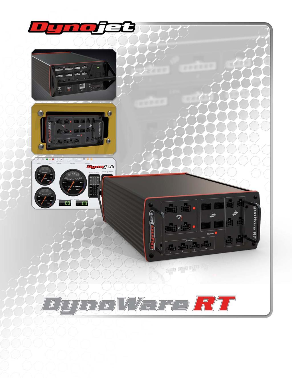
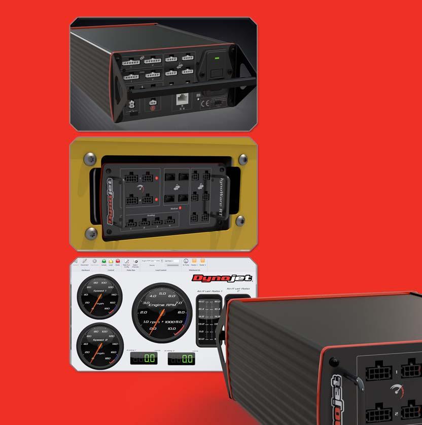
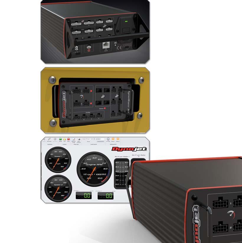
 POWERSPORTS DYNAMOMETER HARDWARE AND SOFTWARE DYNOWARE RT DYNAMOMETER HARDWARE DYNOWARE RT THE NEXT GENERATION OF DYNOJET DYNAMOMETER ELECTRONICS AND SOFTWARE HAS ARRIVED. DynoWare RT is the next generation
Automotive. Accessories
 Dynamometer Catalog Automotive Powersports Accessories Hardware Software and Tuning POWERSPORTS Inertia Only Dynamometers Inertia Only Dynamometers Dynojet s cutting-edge engineering delivers the precise
Version 1.0 Copyright DC-RPM-iBox User Manual
 Version 1.0 Copyright 2012 DC-RPM-iBox User Manual D Y N O C O M S E R I E S C H A S S I S D Y N A M O M E T E R S DC-RPM-iBox User Manual Copyright This manual is copyrighted by Dynocom Industries, Inc.,
Dynojet Research, Inc. All Rights Reserved. User Guide for AutoTune with the Power Vision.
 2012-2015 Dynojet Research, Inc. All Rights Reserved. User Guide for AutoTune with the Power Vision. This manual is copyrighted by Dynojet Research, Inc., hereafter referred to as Dynojet, and all rights
Installation Instructions for: DT2-AF2 Dual Channel & DT2-AF1 Single Channel Wide Band O2 Sensor Controller for A/F (Lambda) Measurement
 Measurement") Installation Instructions for: DT2-AF2 Dual Channel & DT2-AF1 Single Channel Wide Band O2 Sensor Controller for A/F (Lambda) Measurement WARNING: This installation is not for the electrically or mechanically
Installation Instructions for: DT2-AF2 Dual Channel & DT2-AF1 Single Channel Wide Band O2 Sensor Controller for A/F (Lambda) Measurement WARNING: This installation is not for the electrically or mechanically
Automotive. Powersports. Accessories
 Dynamometer Catalog Automotive Powersports Accessories Hardware Software and Tuning POWERSPORTS Inertia Only Dynamometers Inertia Only Dynamometers Dynojet s cutting-edge engineering delivers the precise
*Shown with optional high pressure blowers
 *Shown with optional high pressure blowers SUPERFLOW CYCLEDYN WITH CYCLEDYN YOU CAN The SuperFlow CycleDyn is a chassis dynamometer system, which means that you can select the appropriate Run tests with
POWERSPORTS DYNAMOMETERS TEST EQUIPMENT
 DYNAMOMETER CATALOG POWERSPORTS DYNAMOMETERS TEST EQUIPMENT ACCESSORIES HARDWARE SOFTWARE AND TUNING Your Source For Professional Service Equipment PO Box 80897 Rancho Santa Margarita, CA 92688 Phone:
DynoTune Wideband Gauge
 DISPLAY: RED GREEN BLUE DynoTune Wideband Gauge FACE: BLACK WHITE BEZEL: BLACK SILVER PACKAGE: ROUND SQUARE The DynoTune A/F Gauge will display the air/fuel ratio output from the LC-2 Wide- Band controller.
EasyStart Installation Instructions for Dometic Family RV A/Cs
 EasyStart Installation Instructions for Dometic Family RV A/Cs DuoTherm Brisk Brisk II Penguin Penguin II Contents Introduction... 4 Safety first... 4 Making a good crimp... 4 Identifying Dometic AC Units...
PLEASE READ ALL DIRECTIONS BEFORE STARTING INSTALLATION
 PARTS LIST 2009-2011 Yamaha R1 Installation Instructions 1 Power Commander 1 USB Cable 1 Installation Guide 2 Power Commander Decals 2 Dynojet Decals 2 Velcro strips 1 Dual Lock strip 1 Alcohol swab 1
PLEASE READ ALL DIRECTIONS BEFORE STARTING INSTALLATION
 Parts List 2009-2010 BV300 / Vespa 300GTS Installation Instructions 1 Power Commander FC 1 USB Cable 1 Installation Guide 2 Dynojet Decals 2 Velcro strips 1 Alcohol swab THE IGNITION MUST BE TURNED OFF
INSTALLATION MANUAL. Document revision: 1.3 Last revised: January 2, 2019
 INSTALLATION MANUAL Document revision: 1.3 Last revised: January 2, 2019 Recon SpreadSense Installation Manual 2017-19 Intelligent Agricultural Solutions. All Rights Reserved. Recon SpreadSense Installation
PLEASE READ ALL DIRECTIONS BEFORE STARTING INSTALLATION
 DYNOJET FUEL CONTROLLER PARTS LIST 1 Dynojet Fuel Controller 1 USB Cable 1 CD-ROM 1 Installation Guide 2 Dynojet Decals 2 Velcro 1 Alcohol swab 2008-2010 Honda SH125i/SH150i Installation Instructions PLEASE
Welker Heated Instrument Regulator
 Installation, Operation, and Maintenance Manual Welker Heated Instrument Regulator Model The information in this manual has been carefully checked for accuracy and is intended to be used as a guide for
PLEASE READ ALL DIRECTIONS BEFORE STARTING INSTALLATION
 PARTS LIST 2006-2007 Yamaha R6 Installation Instructions 1 Power Commander 1 USB Cable 1 Installation Guide 2 Power Commander Decals 2 Dynojet Decals 2 Velcro strips 1 Alcohol swab 1 Posi-tap THE IGNITION
PLEASE READ ALL DIRECTIONS BEFORE STARTING INSTALLATION
 PARTS LIST 2007 Harley Davidson Touring Models Installation Instructions 1 Power Commander 1 USB Cable 1 Installation Guide 2 Power Commander Decals 2 Dynojet Decals 2 Zip-ties 2 O2 Optimizers THE IGNITION
PLEASE READ ALL DIRECTIONS BEFORE STARTING INSTALLATION
 PARTS LIST 2015 Yamaha FJ-09 Installation Instructions 1 Power Commander 1 USB Cable 1 Installation Guide 2 Power Commander Decals 2 Dynojet Decals 3 Velcro strips 1 Alcohol swab 1 Posi-tap 1 O2 Optimizer
PLEASE READ ALL DIRECTIONS BEFORE STARTING INSTALLATION
 Parts List 2006-2014 Yamaha Stratoliner/Roadliner 2008-2013 Yamaha Raider Installation Instructions 1 Power Commander FC 1 USB Cable 1 Installation Guide 2 Dynojet Decals 2 Velcro 1 Alcohol swab 1 O2 Optimizer
PLEASE READ ALL DIRECTIONS BEFORE STARTING INSTALLATION
 Parts List 2004-2014 Suzuki GSX-R600/GSX-R750 Installation Instructions 1 Power Commander FC 1 USB Cable 1 Installation Guide 2 Dynojet Decals 2 Velcro 1 Alcohol swab 1 O2 Optimizer THE IGNITION MUST BE
Installation and Operation Manual
 1645 Lemonwood Dr. Santa Paula, CA 93060 USA Toll Free: 1 (800) 253-2363 Tel: 1 (805) 933-9970 rangerproducts.com Ranger Floor Jack Installation and Operation Manual Manual Revision B July 2017 Manual
Prodigy to Encore HD Manual Powder Spray System Upgrade Kit
 Instruction Sheet P/N 60780-0 Prodigy to Encore HD Manual Powder Spray System Upgrade Kit WARNING: Allow only qualified personnel to perform the following tasks. Follow the safety instructions in this
2004, 2008 Autosoft, Inc. All rights reserved.
 Copyright 2004, 2008 Autosoft, Inc. All rights reserved. The information in this document is subject to change without notice. No part of this document may be reproduced, stored in a retrieval system,
PLEASE READ ALL DIRECTIONS BEFORE STARTING INSTALLATION
 Parts List 2008-2011 Yamaha TMax 500 Installation Instructions 1 Power Commander FC 1 USB Cable 1 Installation Guide 2 Dynojet Decals 2 Velcro 1 Alcohol swab THE IGNITION MUST BE TURNED OFF BEFORE INSTALLATION!
EasyStart 364 (ASY-364-X20-IP) Installation Instructions for the Coleman / Airxcel Air Conditioners
 Installation Instructions for the Coleman / Airxcel Air Conditioners") EasyStart 364 (ASY-364-X20-IP) Installation Instructions for the Coleman / Airxcel Air Conditioners using Installation Kit KIT-364-CM1 Contents Introduction... 2 Safety first... 2 Making a good crimp...
EasyStart 364 (ASY-364-X20-IP) Installation Instructions for the Coleman / Airxcel Air Conditioners using Installation Kit KIT-364-CM1 Contents Introduction... 2 Safety first... 2 Making a good crimp...
STATIM CASSETTE AUTOCLAVE TROUBLESHOOTING GUIDE
 STATIM CASSETTE AUTOCLAVE TROUBLESHOOTING GUIDE Version 2.1 Original Statim Error Codes The Statim Sterilizer should never leak steam or have water dripping from under the machine. If either of these conditions
Pre-Installation Guide Performer
 Pre-Installation Guide Performer Contents Structural Requirements... 1 Dental Patient Chair Interface Requirement... 1 Utility Requirements... 1 Utility Specifications... 2 Electrical Ratings... 3 Shipping
Installation Notes for Caterpillar 3306/3456/C15 Gen Set Package. Caterpillar 3306/3456/C15 Generator Set Package. Puradyn Part # Description Qty
 Caterpillar 3306/3456/C15 Generator Set Package Puradyn Part # Description Qty UNIT 15-MTS24 02-00247 02-00248 MTS24 Core Assembly Filter, Size 24 Polydry XD-*01-70001MTS Kit Filter, Size 24 w/ SNG ADD-*01-70001MTS8
SINGLE ACTION FLUID PUMP
 SINGLE ACTION FLUID PUMP MODELS 4490, 4491, 4492 S SERIES A Model 4492 (Stub Pump) Model 4491 (250-275 Gal) Model 4490 (16-55 Gal) Model A52347R-248 (250-275 Gal NOV - 2006 Section -A6 Page -63A Table
4.1 Flow Rate Verification and Adjustment
 4.1 Flow Rate Verification and Adjustment Once the pressure verification is complete (see Chapter 3), the gas flow rate should be verified. Accurate gas flow through the nozzle is critical for achieving
PSB-1 User Manual. Warning!
 PSB-1 User Manual Warning! The Oxygen Sensor used in this device gets very hot in operation. Do not touch a hot sensor. Do not let a hot sensor touch a combustible surface. Do not use the sensor with or
CAUTION: CAREFULLY READ INSTRUCTIONS BEFORE PROCEEDING
 Daytona Sensors LLC Engine Controls and Instrumentation Systems Installation Instructions for Wide-Band Exhaust Gas Oxygen Sensor Interface CAUTION: CAREFULLY READ INSTRUCTIONS BEFORE PROCEEDING OVERVIEW
PLEASE READ ALL DIRECTIONS BEFORE STARTING INSTALLATION
 Parts List 2009-2014 Yamaha YFZ450 R/X Installation Instructions 1 Power Commander FC 1 USB Cable 1 Installation Guide 2 Dynojet Decals 2 Velcro 1 Alcohol swab THE IGNITION MUST BE TURNED OFF BEFORE INSTALLATION!
Wide Band Air Fuel Ratio meter (Bosch LSU 4.9 sensors)
") Wide Band Air Fuel Ratio meter (Bosch LSU 4.9 sensors) Overview- Air Fuel Ratio (AFR) meter & display Interfaces to DYNertia3 or data loggers, It can also be used as a rugged professional stand-alone unit.
Wide Band Air Fuel Ratio meter (Bosch LSU 4.9 sensors) Overview- Air Fuel Ratio (AFR) meter & display Interfaces to DYNertia3 or data loggers, It can also be used as a rugged professional stand-alone unit.
DynoTune Wideband Gauge
 DISPLAY: RED GREEN BLUE DynoTune Wideband Gauge FACE: BLACK WHITE BEZEL: BLACK SILVER PACKAGE: ROUND SQUARE The DynoTune A/F Gauge will display the air/fuel ratio output from the LC-1 Wide-Band controller.
CAUTION: CAREFULLY READ INSTRUCTIONS BEFORE PROCEEDING
 Daytona Sensors LLC Engine Controls and Instrumentation Systems Installation Instructions for WEGO IIID Wide-Band Exhaust Gas Oxygen Sensor Interface (Automotive Version) CAUTION: CAREFULLY READ INSTRUCTIONS
Lube Level Maintainer
 Lube Level Maintainer Models LM2000/LM2000S Installation Instructions 00-02-0423 Revised 08-12-09 Section 15 In order to consistently bring you the highest quality, full featured products, we reserve the
WALCHEM LINEAR POLARIZATION RESISTANCE CORROSION SENSORS Instruction Manual
 WALCHEM LINEAR POLARIZATION RESISTANCE CORROSION SENSORS Instruction Manual 1 Notice 2018 WALCHEM, Iwaki America Inc. (hereinafter Walchem ) 5 Boynton Road, Holliston, MA 01746 USA (508) 429-1110 All Rights
SmarTire TPMS Maintenance Hand Tool. Revision User Manual
 SmarTire TPMS Maintenance Hand Tool Revision 1.03 User Manual Page 2 Table of Contents FCC Compliance Label...4 User Interface Illustration...4 Introduction...5 Testing Tire Sensors...5 Main Menu...6 Main
User s Guide For Control Pressure Gauge
 User s Guide For Note: The fuel system should be under pressure even when the car is off. ALWAYS follow these precautions: 1. Always wear safety glasses. 2. When the fuel lines are first loosened about
215 Gallon Waste Oil Tank With Metering Pump Installation Instructions
 215 Gallon Waste Oil Tank With Metering Pump Installation Instructions Lanair Products LLC 4109 Capital Circle Janesville, Wisconsin 53546 1-888-370-6531 www.lanair.com BEFORE YOU BEGIN INSTALLATION...
DIESEL EXHAUST FLUID PUMPING ACCESSORIES INSTALLATION GUIDE
 DIESEL EXHAUST FLUID PUMPING ACCESSORIES INSTALLATION GUIDE The information in this publication is provided for reference only. While every effort has been made to ensure the reliability and accuracy of
Lamp House with 2.5 kw lamp
 Lamp House with 2.5 kw lamp Installation manual For HDX series R9864130 R5905109/04 27/05/2014 Barco nv, Events Noordlaan 5, B-8520 Kuurne Phone: +32 56.36.82.11 Fax: +32 56.36.88.24 Support: www.barco.com/esupport
5000TOC Sensor Service Manual
 Part No. 84449 5000TOC Sensor Service Manual This document contains proprietary information, which is protected by copyright. All rights are reserved. No part of this document may be photocopied (other
EFI Harley Davidson 1340 EVO
 Floppy Disc Request Form If you do not have a CD-Rom drive and would like to receive the program and the alternate maps for your model on a 3 1/2 floppy disc, please fax this form to Dynojet at 1-702-399-1431
APSX WIDEBAND D2 AFR CONTROLLER GAUGE. Installation and User Manual. APSX WIDEBAND D2 Manual V1.0
 APSX WIDEBAND D2 AFR CONTROLLER GAUGE Installation and User Manual APSX WIDEBAND D2 Manual V1.0 You purchased a wideband gauge! BENCH TEST BEFORE INSTALLING IT! USE A RELIABLE 12V POWER > 5AMP Stock (OEM)ECU
CAUTION: CAREFULLY READ INSTRUCTIONS BEFORE PROCEEDING
 Daytona Sensors LLC Engine Controls and Instrumentation Systems Installation Instructions for WEGO II Wide-Band Exhaust Gas Oxygen Sensor Interface Methanol Version CAUTION: CAREFULLY READ INSTRUCTIONS
Jerome DOSIMETER POCKET PUMP OPERATOR S MANUAL
 Jerome DOSIMETER POCKET PUMP OPERATOR S MANUAL September 2011 Arizona Instrument LLC 3375 N Delaware Street Chandler, AZ 85225 (602) 470-1414 (800) 528-7411 http://www.azic.com e-mail: azi@azic.com - General
Haas Hydraulic Power Unit - Troubleshooting Guide
 Haas Technical Documentation Haas Hydraulic Power Unit - Troubleshooting Guide Scan code to get the latest version of this document Translation Available A: Haas HPU for most lathes made before 2016. B:
PLEASE READ ALL DIRECTIONS BEFORE STARTING INSTALLATION
 Parts List 2008-2014 Honda CBR1000RR Installation Instructions 1 Power Commander FC 1 USB Cable 1 Installation Guide 2 Dynojet Decals 2 Velcro 1 Alcohol swab 1 O2 Optimizer THE IGNITION MUST BE TURNED
DP3 Pump. 3:1, Air-operated, Oil. General. Operation. Technical Data. Installation R0 10/09. 35a 35b 35c
 DP3 Pump 3:1, Air-operated, Oil General The DP3 Pump is a compressed air-operated piston reciprocating medium pressure pump. Suitable for medium flow transfer of high viscosity lubricants and for oil delivery
SmarTire TPMS Maintenance Hand Tool. Revision User Manual
 SmarTire TPMS Maintenance Hand Tool Revision 1.04 User Manual Page 2 Table of Contents FCC Compliance Label... 4 User Interface Illustration... 4 Introduction... 5 Testing Tire Sensors... 5 Main Menu...
Prodigy HDLV System Troubleshooting - Generation III
 Prodigy HDLV System Troubleshooting - Generation III Instruction Sheet P/N 1081071-05 Use the procedures listed in this document to isolate and correct common problems with Prodigy HDLV Systems. Refer
Kawasaki Vulcan 1500 Classic
 Floppy Disc Request Form If you do not have a CD-Rom drive and would like to receive the program and the alternate maps for your model on a 3 1/2 floppy disc, please fax this form to Dynojet at 1-702-399-1431
THE BENCHMARK FOR AN ENTIRE INDUSTRY
 Dynojet Research Inc. has established a reputation for manufacturing innovative leading edge dynamometers, THAT HAVE BECOME THE BENCHMARK FOR AN ENTIRE INDUSTRY. The Dynojet Dynamometer is a revolutionary
Blow Off Valve Retrofit Kit
 Instruction Sheet P/N 37 56C low Off Valve Retrofit Kit WRNING: llow only qualified personnel to perform the following tasks. Follow the safety instructions in this document and all other related documentation..
INSTALLATION, OPERATION, AND MAINTENANCE MANUAL WELKER INJECTION PUMP
 INSTALLATION, OPERATION, AND MAINTENANCE MANUAL WELKER INJECTION PUMP MODEL SSO-8 DRAWING NUMBERS AD148CF AD148CG AD148CO AD148CQ AD500CA MANUAL NUMBER IOM-065 REVISION Rev. A, 8/17/2016 TABLE OF CONTENTS
Installation & Operation Manual. IMPORTANT: This manual contains important information. READ AND KEEP FOR REFERENCE.
 Elecronic Preset Meter 2 Industrial Handheld Series Model EPM2-IND Standard Series IMPORTANT: This manual contains important information. READ AND KEEP FOR REFERENCE. IOM-139-02-EN (1-12) 53400-139 Rev.
HV angle valve with single acting pneumatic actuator and closing spring (NC)
") Installation, Operating & Maintenance Instructions HV angle valve with single acting pneumatic actuator and closing spring (NC) Series 264 DN 100 160 mm (I. D. 4 6 ) This manual is valid for the following
Installation, Operating & Maintenance Instructions HV angle valve with single acting pneumatic actuator and closing spring (NC) Series 264 DN 100 160 mm (I. D. 4 6 ) This manual is valid for the following
INSTALLATION, OPERATION, AND MAINTENANCE MANUAL WELKER SAMPLE / INJECTION PUMP
 INSTALLATION, OPERATION, AND MAINTENANCE MANUAL WELKER SAMPLE / INJECTION PUMP MODEL SSO-9MED DRAWING NUMBERS AD243DI AD243DK AD243DK.K1 MANUAL NUMBER IOM-175 REVISION Rev. B, 3/21/2017 TABLE OF CONTENTS
PLEASE READ ALL DIRECTIONS BEFORE STARTING INSTALLATION
 Parts List 2013-2014 Honda CBR600RR Installation Instructions 1 Power Commander FC 1 USB Cable 1 Installation Guide 2 Dynojet Decals 2 Velcro 1 Alcohol swab 1 O2 Optimizer THE IGNITION MUST BE TURNED OFF
PLEASE READ ALL DIRECTIONS BEFORE STARTING INSTALLATION
 Parts List 2004-2007 Honda CBR1000RR Installation Instructions 1 Power Commander FC 1 USB Cable 1 Installation Guide 2 Dynojet Decals 2 Velcro 1 Alcohol swab THE IGNITION MUST BE TURNED OFF BEFORE INSTALLATION!
AutoDose Automatic Dispensing System
 AutoDose Automatic Dispensing System The AutoDose TM is a battery or A/C-powered peristaltic pumping dispenser that runs automatically at preset times as programmed with an electronic timer / control.
CAUTION: CAREFULLY READ INSTRUCTIONS BEFORE PROCEEDING
 Daytona Sensors LLC Engine Controls and Instrumentation Systems Installation Instructions for Wide-Band Exhaust Gas Oxygen Sensor Interface CAUTION: CAREFULLY READ INSTRUCTIONS BEFORE PROCEEDING OVERVIEW
PLEASE READ ALL DIRECTIONS BEFORE STARTING INSTALLATION
 PARTS LIST 2008-2009 Yamaha R6 Installation Instructions 1 Power Commander 1 USB Cable 1 CD-ROM 1 Installation Guide 2 Power Commander Decals 2 Dynojet Decals 2 Velcro 1 Alcohol swab 1 Posi-tap 1 O2 optimizer
HDMD-200/300 Universal display
 Universal display I n s ta l l at i o n G u i d e Micro Display Kit 9 Mendenhall Drive North Las Vegas, NV 8908 www.dynojet.com -800-99-4993 www.dynojet.com Display unit Attachment Pegs Cable Harness Hex
Automated Liquid Handling Station
 Automated Liquid Handling Station Quick Installation Guide Manual Part Number 32-0406-048 Rev 0 COPYRIGHT 2018 Teledyne Technologies Incorporated. All rights reserved. 32-0406-048 Rev 0, May, 2018 Printed
Installation instructions
 Installation instructions Akrapovič Exhaust System: Slip-On for the Porsche 911 Carrera (type 991) Porsche 911 Carrera S (type 991) Porsche 911 Carrera 4 (type 991) Porsche 911 Carrera 4S (type 991) Please
Part # for Sportster Models
 Part # 309-365 for Sportster Models Thank you for purchasing a ThunderMax ECM! Please read through the following instructions before beginning the installation procedure. Following these instructions will
AssayMAP 96AM Wash Station. Maintenance Guide
 AssayMAP 96AM Wash Station Maintenance Guide Notices Agilent Technologies, Inc. 2018 No part of this manual may be reproduced in any form or by any means (including electronic storage and retrieval or
CONTACTING CONDUCTIVITY GENERAL PURPOSE SENSORS Instruction Manual
 CONTACTING CONDUCTIVITY GENERAL PURPOSE SENSORS Instruction Manual Notice 2018 WALCHEM, Iwaki America Inc. (hereinafter Walchem ) 5 Boynton Road, Holliston, MA 01746 USA (508) 429-1110 All Rights Reserved
LS10.0T Service Manual
 LS10.0T Service Manual 1 TABLE OF CONTENTS CHAPTER 1: SERIAL NUMBER LOCATION...3 CHAPTER 2: PREVENTATIVE MAINTENANCE 2.1 Preventative Maintenance. 4 2.2 Tension and Centering the Running Belt....6 CHAPTER
PRSalpha Air Drill (Double Valve)
") 888-680-4466 ShopBotTools.com PRSalpha Air Drill (Double Valve) Copyright 2016 ShopBot Tools, Inc. page 1 Copyright 2016 ShopBot Tools, Inc. page 2 Table of Contents Overview...5 Spindle Mounting Plate...6
888-680-4466 ShopBotTools.com PRSalpha Air Drill (Double Valve) Copyright 2016 ShopBot Tools, Inc. page 1 Copyright 2016 ShopBot Tools, Inc. page 2 Table of Contents Overview...5 Spindle Mounting Plate...6
Bubble Machine. User Manual
 Bubble Machine User Manual TABLE OF CONTENTS 1. Before You Begin... 3 What Is Included... 3 Unpacking Instructions... 3 Claims... 3 Text Conventions... 3 Icons... 3 Document Information... 3 Product at
USER MANUAL LVC-200TC DIGITAL THERMOCOUPLE VACUUM GAUGE
 USER MANUAL LVC-200TC DIGITAL THERMOCOUPLE VACUUM GAUGE CONTACT US PHONE/FAX Toll Free: 800.465.1004 Phone: 801.486.1004 Fax: 801.486.1007 ADDRESS LACO Technologies, Inc. 3085 West Directors Row Salt Lake
US Models Only EFI Harley Davidson Twin Cam 88 Touring Models. Floppy Disc Request Form
 Floppy Disc Request Form If you do not have a CD-Rom drive and would like to receive the program and the alternate maps for your model on a 3 1/2 floppy disc, please fax this form to Dynojet at 1-702-399-1431
Statim G4 Error Codes
 Statim G4 Error Codes All leaks should be corrected before proceeding with troubleshooting Cycle Fault #1 The cassette temperature failed to reach 95 C within a time-out period. 1. An extremely large steam