KMIR. Multi outdoor units. troubleshooting Multi zone CONDENSING UNITS MKMIR218-H221, KMIR327-H217, KMIR436-H217, KMIR545-H219.
|
|
|
- Lester Gallagher
- 6 years ago
- Views:
Transcription


1 Multi outdoor units KMIR troubleshooting Multi zone CONDENSING UNITS Model Numbers: MKMIR218-H221, KMIR327-H217, KMIR436-H217, KMIR545-H219 Table of Contents 1. Trouble Shooting WARNING Installation MUST conform with local building codes or, in the absence of local codes, with the National Electrical Code NFPA70/ANSI C or current edition and Canadian Electrical Code Part1 CSA C The information contained in the manual is intended for use by a qualified service technician familiar with safety procedures and equipped with the proper tools and test instruments Installation or repairs made by unqualified persons can result in hazards to you and others. Failure to carefully read and follow all instructions in this manual can result in equipment malfunction, property damage, personal injury and/or death.
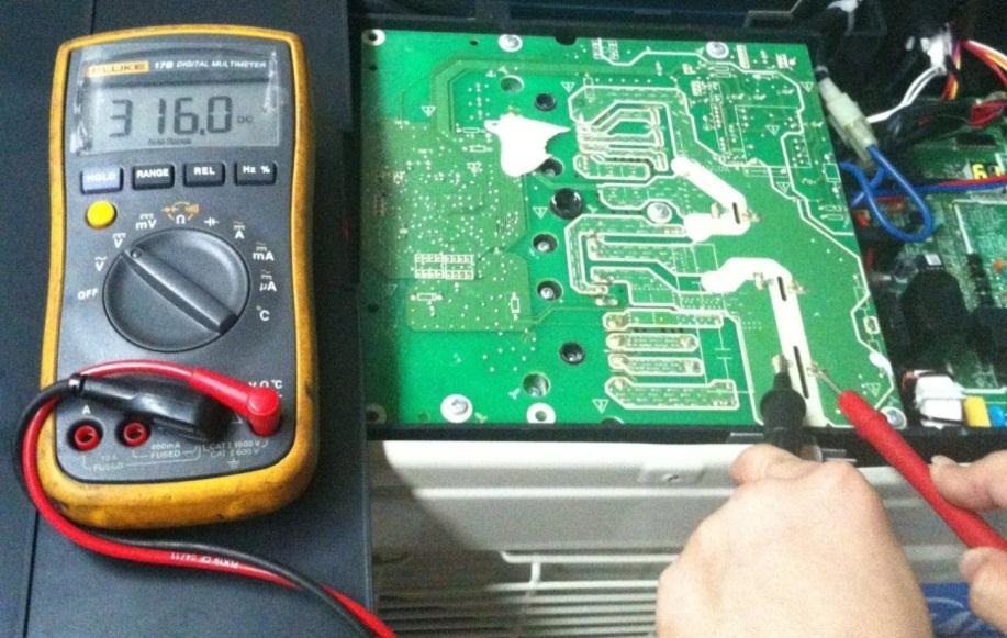
2 8. Troubleshooting 8.1Safety Because of there are capacitors in PCB and relative circuit in outdoor unit, even shut down the power supply, electricity power still are kept in capacitors, do not forget to discharge the electricity power in capacitor. The value of resistance is about 1500 ohm to 2000 ohm Electrolytic Capacitors (HIGH VOLTAGE! CAUTION!) Bulb (25-40W)
3 The voltage in P3 and P4 in outdoor PCB is high voltage about 310V The voltage in P5 and P6 in outdoor PCB is high voltage about 310V 8.2 Indoor Unit Error Display Console series Operation Timer De-frost Failure X X Open or short circuit of T1 temperature sensor X X Open or short circuit of T2 temperature sensor X X Communication malfunction between indoor and outdoor units X Indoor EEPROM malfunction X Outdoor fan speed has been out of control X IPM module protection Open or short circuit of T3 or T4 temperature sensor or Outdoor unit EEPROM parameter error X Temperature protection of compressor top X Mode conflict X Inverter compressor drive protection Indoor fan speed has been out of control flash at 5Hz, light, X extinguished, flash at 0.5Hz For KDIR09-H2, KDIR12-H2, KDIR18-H2, KDIR24-H2, KTIR09-H2, KTIR12-H2, KTIR18-H2: Operatio n Timer De-frost Alarm Failure Display ODU Error code X X X Open or short circuit of T1 temperature sensor E0 X X X Open or short circuit of T2 temperature sensor E1 X X X Communication malfunction between indoor and outdoor units X X X Water-level alarm malfunction E3 X X Indoor EEPROM malfunction E4 X X IPM module protection E5 P6 E2 E2 X X Open or short circuit of T3 or T4 temperature sensor or outdoor EEPROM malfunction E6 E0,E4
4 X Outdoor fan has been out of control E7 E8 X Indoor fan speed has been out of control F5 X Voltage protection P0 E5 X X Temperature protection of compressor top. P1 P0 X Outdoor unit over-current protection P2 P3 X X Inverter compressor drive protection P4 X Mode conflict P5 flash at 2.5Hz, light, X extinguished,, flash at 0.5Hz te: Digital display is only available for duct type. Oasis series: Operation lamp Timer lamp Display LED STATUS 1 time X E0 Indoor EEPROM malfunction 2 times X E1 Communication malfunction between indoor and outdoor units 4 times X E3 Indoor fan speed malfunction. 5 times X E4 Indoor room temperature sensor open or short circuit. 6 times X E5 Evaporator coil temperature sensor open or short circuit. 2 times F1 Outdoor temperature sensor open or short circuit. 3 times F2 Condenser coil temperature sensor open or short circuit. 4 times F3 Compressor discharge pipe sensor open or short circuit. 5 times F4 Outdoor EEPROM malfunction 6 times F5 Outdoor fan has been out of control 7 times F6 Indoor unit coil outlet temp. sensor open or short circuit. 1 times P0 Inverter module (IPM) malfunction or IGBT over-strong current protection 2 times P1 Voltage(High voltage or low voltage ) protection. 3 times P2 High temperature protection of compressor top (only for M3OD-27HRDN1-M) 5 times P4 Compressor drive error 6 times P5 Mode conflict ODU Error E2 E4 E4 E4 E0 E8 E4 P6 E5 P0 flash, light, X extinguished 8.3 Outdoor Unit Display Outdoor unit point check function There is a check switch in outdoor PCB.

5 Push the switch SW1 to check the states of unit when the unit is running. The digital display tube will display the follow procedure when push SW1 each time. Display Remark 0 rmal display Display running frequency, running state or malfunction code 1 Quantity of indoor units in good connection Actual data Display Number of indoor unit Outdoor unit running mode code Off:0,Fan only 1, Cooling:2, Heating:3, Forced cooling:4 3 A indoor unit capacity 4 B indoor unit capacity 5 C indoor unit capacity 6 D indoor unit capacity 7 E indoor unit capacity The capacity unit is horse power. If the indoor unit is not connected, the digital display tube will show: (9K:1HP,12K:1.2HP,18K:1.5HP)
6 8 A Indoor unit capacity demand code 9 B Indoor unit capacity demand code 10 C Indoor unit capacity demand code 11 D Indoor unit capacity demand code 12 E Indoor unit capacity demand code rm code*hp (9K:1HP,12K:1.2HP,18K:1.5HP) 13 Outdoor unit amendatory capacity demand code Forced cooling:7 14 The frequency corresponding to the total indoor units amendatory capacity demand 15 The frequency after the frequency limit 16 The frequency sending to compressor control chip 17 A indoor unit evaporator outlet temp.(t 2BA) 18 B indoor unit evaporator outlet temp.(t 2BB) 19 C indoor unit evaporator outlet temp.(t 2BC) 20 D indoor unit evaporator outlet temp.(t 2BD) 21 E indoor unit evaporator outlet temp.(t 2BE) If the temp. is lower than -9 degree, the digital display tube will show -9.If the temp. is higher than 70 degree, the digital display tube will show 70. If the indoor unit is not connected, the digital display tube will show: 22 A indoor unit room temp.(t 1A) If the temp. is lower than 0 degree, the digital display tube will show 0.If the 23 B indoor unit room temp.(t 1B) temp. is higher than 50 degree, the digital display tube will show 50. If the indoor unit is not connected, the digital display tube will show: 24 C indoor unit room temp.(t 1C) 25 D indoor unit room temp.(t 1D) 26 E indoor unit room temp.(t 1E) 27 A indoor unit evaporator temp.(t 2A) 28 B indoor unit evaporator temp.(t 2B) 29 C indoor unit evaporator temp.(t 2C) 30 D indoor unit evaporator temp.(t 2D) 31 E indoor unit evaporator temp.(t 2E) 32 Condenser pipe temp.(t3) 33 Outdoor ambient temp.(t4) If the temp. is lower than -9 degree, the digital display tube will show -9.If the temp. is higher than 70 degree, the digital display tube will show 70. If the indoor unit is not connected, the digital display tube will show: 34 Compressor discharge temp.(tp) The display value is between 30~129 degree. If the temp. is lower than 30 degree, the digital display tube will show 30.If the temp. is higher than 99 degree, the digital display tube will show single digit and tens digit. For example, the digital display tube show 0.5,it means the compressor discharge temp. is 105 degree.) 35 AD value of current The display value is hex number. 36 AD value of voltage For example,the digital display tube show Cd, it means AD value is EXV open angle for A indoor unit 38 EXV open angle for B indoor unit 39 EXV open angle for C indoor unit 40 EXV open angle for D indoor unit 41 EXV open angle for E indoor unit 42 Frequency limit symbol Actual data/4. If the value is higher than 99, the digital display tube will show single digit and tens digit. For example,the digital display tube show 2.0,it means the EXV open angle is 120 4=480p.) Bit7 Bit6 Frequency limit caused by IGBT radiator Frequency limit caused by PFC Bit5 Frequency limit caused by T4. Bit4 Frequency limit caused by T2. Bit3 Frequency limit caused by T3. Bit2 Frequency limit caused by T5. Bit1 Bit0 Frequency limit caused by current Frequency limit caused by voltage The display value is hex number. For example, the digital display tube show 2A,then Bit5=1, Bit3=1, Bit1=1. It means frequency limit caused by T4,T3 and current.
7 43 Average value of T2 (Sum T2 value of all indoor units)/( number of indoor units in good connection) 44 Outdoor unit fan motor state Off:0, High speed:1, Med speed:2, Low speed:3 Breeze:4, Super breeze:5 45 The last error or protection code 00 means no malfunction and protection 46 F indoor unit capacity 47 F Indoor unit capacity demand code 48 F indoor unit evaporator outlet temp.(t 2BF) 49 F indoor unit room temp.(t 1F) 50 F indoor unit evaporator temp.(t 2F) 51 EXV open angle for F indoor unit Outdoor unit s digital display tube There is a digital display tube in outdoor PCB. Digital display tube display function In standby, the LED displays - - In compressor operation, the LED display the running frequency, In defrosting mode, The LED displays df or alternative displays between running frequency and df (each displays 0.5s) In compressor pre-heating, The LED displays PH or alternative displays between running frequency and PH (each displays 0.5s) During the oil return process, The LED displays RO or alternative displays between running frequency and RO (each displays 0.5s) In low ambient cooling mode, the LED displays LC or alternative displays between running frequency and LC (each displays 0.5s) In forced cooling mode, the LED displays FC or alternative displays between running frequency and FC (each displays 0.5s) When PFC module protection occurs three times within 15 minutes, the LED displays E6 or alternative displays between running frequency and E6 (each displays 0.5s) In protection or malfunction, the LED displays error code or protection code.
8 8.3.3 Outdoor unit error display Display LED STATUS IDU Error (Oasis) IDU Error (CTBU) E0 Outdoor EEPROM malfunction F4 E6 E2 Communication malfunction between indoor and outdoor units E1 E2 E3 E4 Communication malfunction between IPM board and outdoor main board Open or short circuit of outdoor temperature sensor (T3 T4 T5 T2B) E5 Voltage protection P1 P0 E6 Active PFC module protection E8 F1 F2 F3 F4 F5 F6 Outdoor fan speed has been out of control (Only for DC fan motor models) A Indoor unit coil outlet temp. sensor or connector of sensor is defective B Indoor unit coil outlet temp. sensor or connector of sensor is defective C Indoor unit coil outlet temp. sensor or connector of sensor is defective D Indoor unit coil outlet temp. sensor or connector of sensor is defective E Indoor unit coil outlet temp. sensor or connector of sensor is defective F Indoor unit coil outlet temp. sensor or connector of sensor is defective F2 E6 F5 P0 Temperature protection of compressor top P2 P3(P1) P1 High pressure protection P2 Low pressure protection P3 Current protection of compressor (P2) P4 Temperature protection of compressor discharge P5 High temperature protection of condenser P6 IPM module protection P0 E5
9 8.4 Diagnosis and Solution Indoor unit trouble shooting Indoor EEPROM malfunction diagnosis and solution. Malfunction decision conditions Trouble shooting: PCB main chip does not receive feedback from EEPROM chip Installation mistake PCB faulty Shut off the power supply and turn it on 1 minute later. Is it still displaying the error code? If the EEPROM chip is welded on PCB, replace the PCB directly. Otherwise, check whether the EEPROM chip plugged in PCB well? Insert the EEPROM well Supposed causes Replace the indoor PCB. EEPROM: a read-only memory whose contents can be erased and reprogrammed using a pulsed voltage. For the location of EEPROM chip, please refer to the below photos.
10 Communication malfunction between indoor and outdoor units diagnosis and solution. Malfunction decision conditions Supposed causes Indoor unit does not receive the feedback from outdoor unit during 120 seconds. Wiring mistake Indoor or outdoor PCB faulty Trouble shooting:
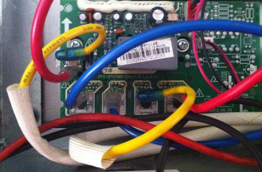
11 Indoor / outdoor units communication error Start: Power off, then Power on the A/C by the Breaker. (reconnect the power wire). Is it still displaying the error code? Check wiring on the outdoor and indoor terminal follow the wiring diagram. Is all connecting correctly? Reconnect the wiring Reconnect the wiring Turn on all indoor unit by remote controller. Is all indoor unit display Measure Vs, is it moving alternately between positive value and negative value? (Vs is the voltage between S and L2). Refer PIC 1 A: Is all the wiring between terminal and Indoor PCB connect ok? Change the Indoor PCB Turn off the all indoor units. Is IPM power LED or operating LED lamp On? Refer PIC2 change IPM Power on by remote controller, IIs it still displaying the error code after 3 minutes? Is main board lamp on? Refer PIC 3. Is the reactor connecting well? Reconnect the wiring Change Outdoor Main PCB Is indoor units number correct? Check on the outdoor check point. (2 for dual zone, 3 for tri zone, 4 for qua zone). Refer PIC 4. Trouble is solved first time second time A Change outdoor unit PCB assembly(include wiring) totally

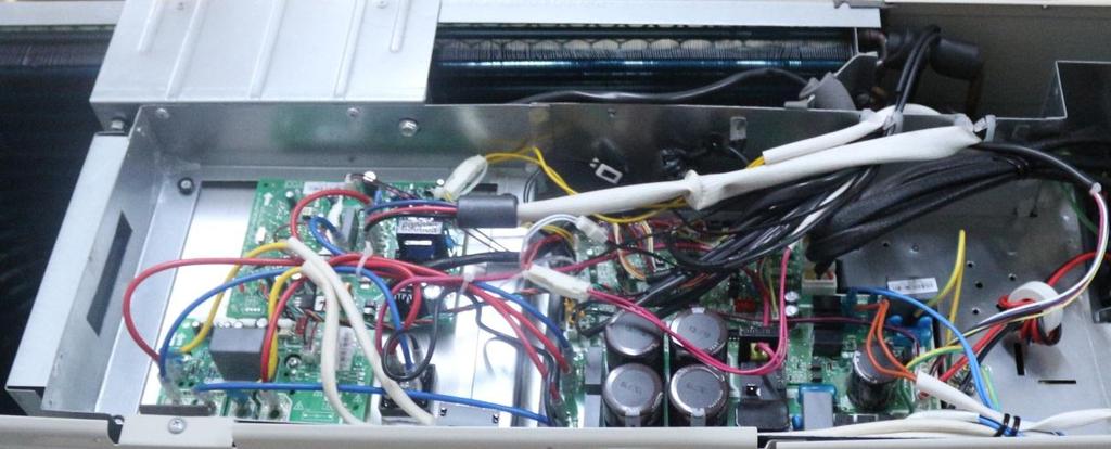
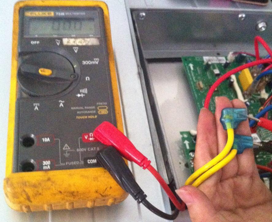
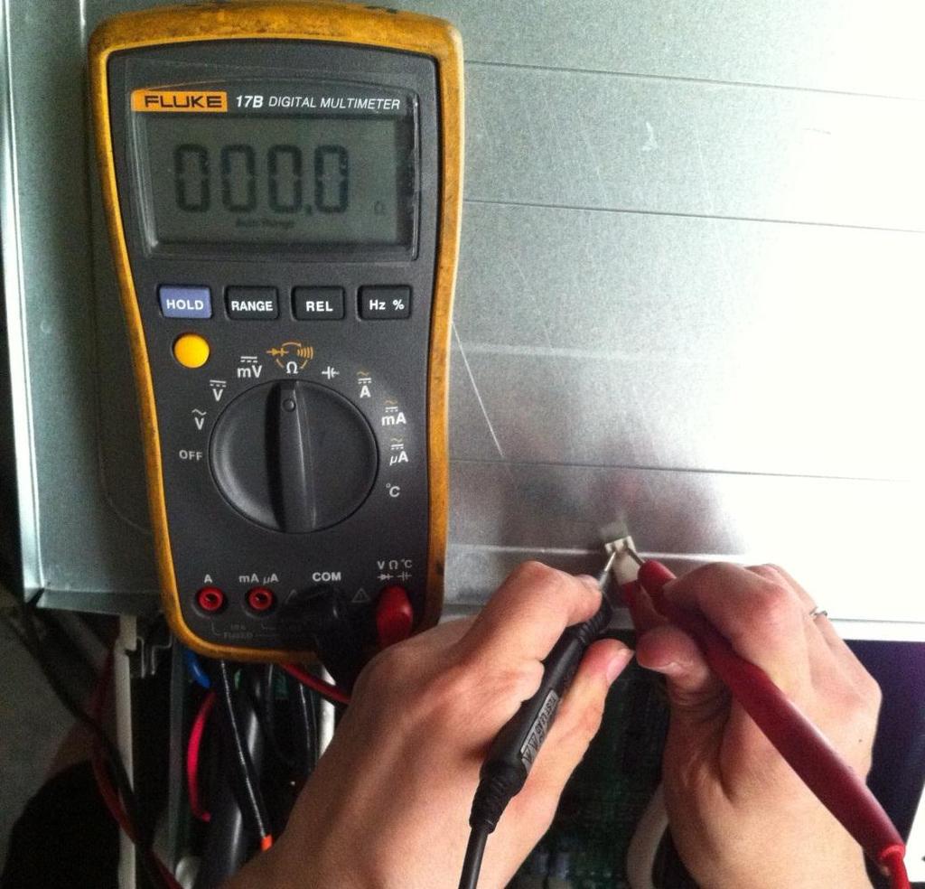
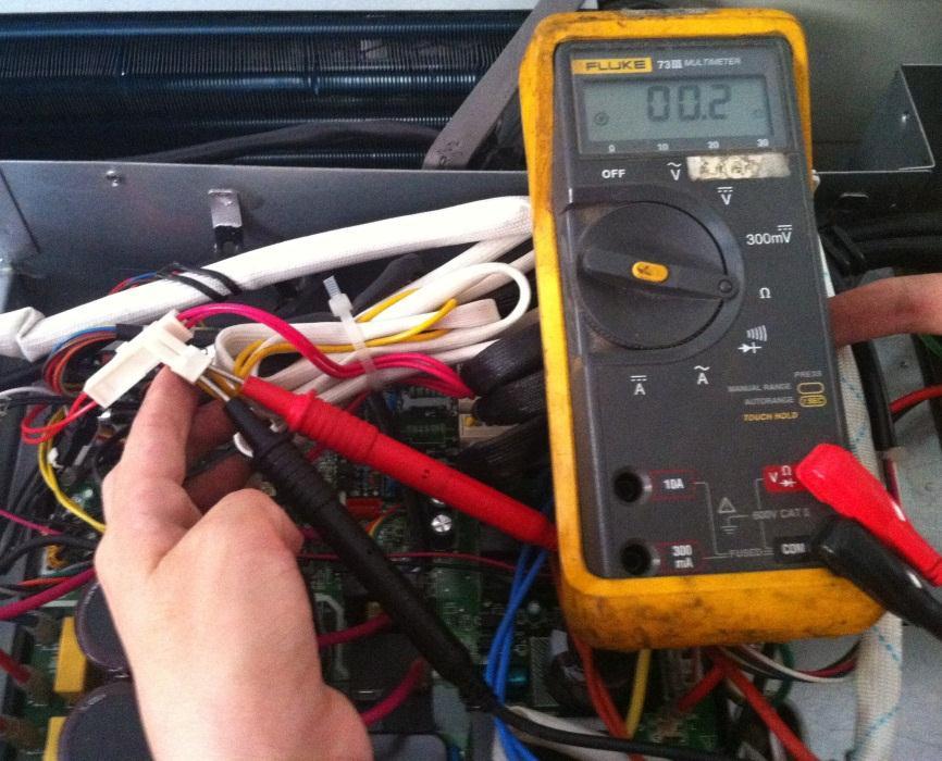
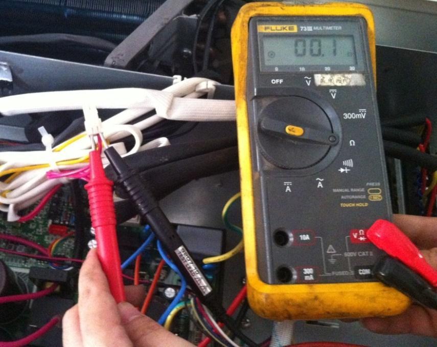
12 Pic 1: Use a multimeter to test the DC voltage between L2 port and S port of outdoor unit. The red pin of multimeter connects with L2 port while the black pin is for S port. When AC is normal running, the voltage will move alternately between positive value and negative value. Pic 2: IPM (for dual/tri/qua-zone) Power (some modles) Self-Check OK Operating
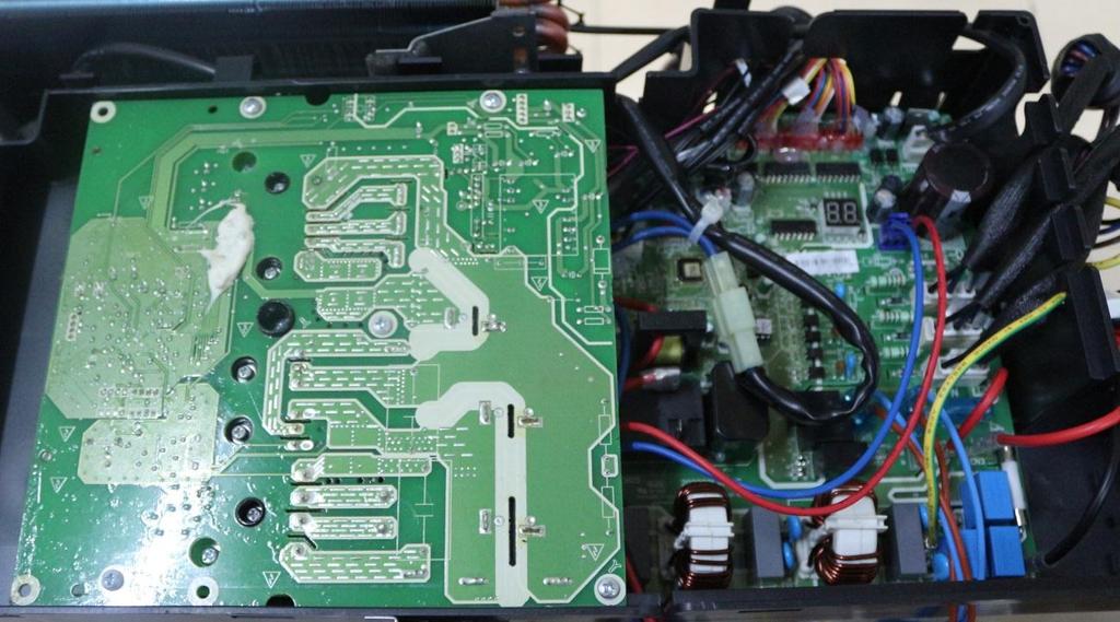
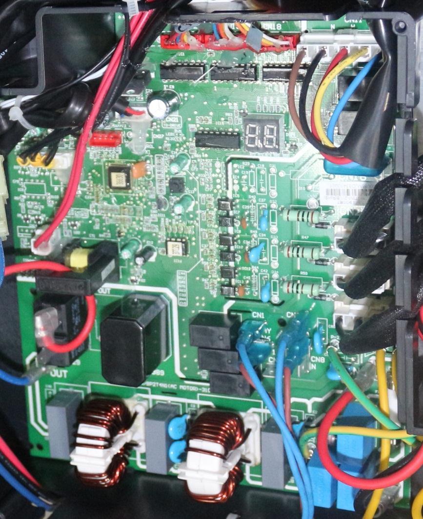
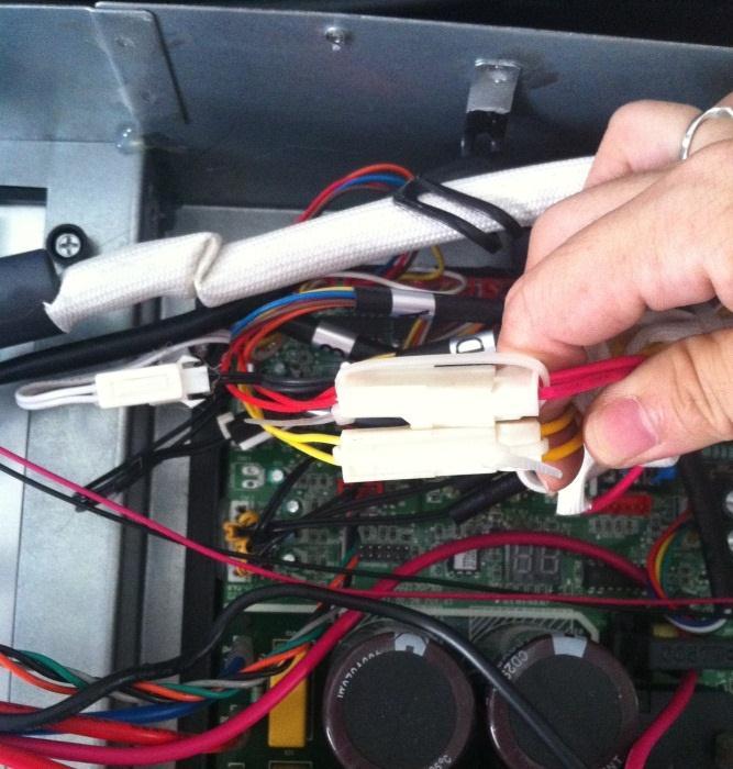
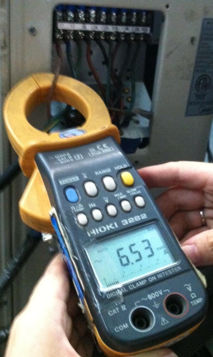
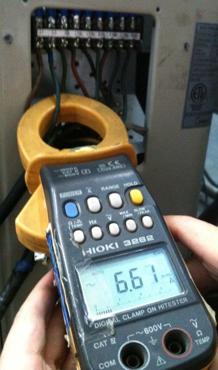
13 PIC3: Main board LED when power on and unit standby. PIC 4: Check point button, press 1 time for check how many indoor units are connected.
14 zero-crossing signal error diagnosis and solution. Malfunction decision conditions When PCB does not receive zero crossing signal feedback for 4 minutes or the zero crossing signal time interval is abnormal. Supposed causes Connection mistake PCB faulty Trouble shooting: Check if the connections and power supply is normal? Correct the connections. Turn on the unit when the power supply is good. Indoor main PCB is defective. Replace indoor main PCB.
15 Indoor fan speed has been out of control diagnosis and solution. Malfunction decision conditions When indoor fan speed keeps too low (300RPM) for certain time, the unit will stop and the LED will display the failure. Supposed causes Wiring mistake Fan ass y faulty Fan motor faulty PCB faulty Trouble shooting: Shut off the power supply and turn it on 1 minute later. Is it still displaying the error code? The unit operates normally. Shut off the power supply, rotate the fan by hand. Does it rotate properly? Find out the cause and have it solved. For example, check whether the fan is blocked or the bearing is broken? Check the wires of fan motor. Are all the connections good? Correct the connections. Check whether the fan motor is normal through index 1? Replace the fan motor If the malfunction is still existing, replace the main PCB Check whether the main PCB is normal through index 2? Replace the main PCB. The malfunction is solved?
16 Index 1: 1: Indoor AC fan motor Power on and set the unit running in fan mode at high fan speed. After running for 15 seconds, measure the voltage of pin1 and pin2. If the value of the voltage is less than 100V (208~240V power supply)or 50V(115V power supply), the PCB must have problems and need to be replaced. 2. Indoor DC fan motor (control chip is inside fan motor) Power on and when the unit is in standby, measure the voltage of pin1-pin3, pin4-pin3 in fan motor connector. If the value of the voltage is not in the range showing in below table, the PCB must have problems and need to be replaced. For other models: DC motor voltage input and output NO. Color Signal Voltage 1 Red Vs/Vm 200V~380V Black GND 0V 4 White Vcc V 5 Yellow Vsp 0~6.5V 6 Blue FG V
17 Open or short circuit of temperature sensor diagnosis and solution. Malfunction decision conditions If the sampling voltage is lower than 0.06V or higher than 4.94V, the LED will display the failure. Supposed causes Wiring mistake Sensor faulty PCB faulty Trouble shooting: Check the connections between temperature sensor and PCB. Are the connections good? Correct the connections. Check the resistance value of the sensor via Appendix 1 and Appendix 2 Is it normal? Replace indoor or outdoor PCB. Replace the sensor
18 IPM module or IGBT over-strong current protection diagnosis and solution. Malfunction decision conditions Supposed causes Trouble shooting: When the voltage signal that IPM send to compressor drive chip is abnormal, the display LED will show P6 and AC will turn off. Wiring mistake IPM malfunction Outdoor fan ass y faulty Compressor malfunction Outdoor PCB faulty
19 IPM module protection Check whether the voltage range of P-N on IPM module is normal? DC V for 18-27KBtu/h; DC V for 36KBtu/h Check whether the input power supply is correct? V, 1N, 60Hz Regulate it to correct, then check whether the system can work normally? Check whether the connecting line between main board and the IPM module is connected tightly Connect it tightly, check ok or not? Check whether the power supply line is connected correctly and tightly Connect it correctly and tightly, check ok or not? Check whether the connecting line of the compressor is connected correctly or tightly Connect it well, check ok or not? Check whether the lines in E-part box are connected tightly Connect it tightly, check ok or not? Replace the IPM module, check whether the system can work normally? Check if the outdoor fan runs properly or the outdoor unit ventilation is good. Replace the main board; check whether the system can work normally? For AC fan models, please refer to 9.4 Trouble Criterion Of Main Parts, check whether the resistance of the fan motor is normal. If not, replace the fan motor. For DC fan models, refer to the solution of fan speed has been out of control malfunction. Find out the cause and have it solved. Check whether the bridge rectifiers are normal? Use the multimeter to measure the resistance between each two terminals, check whether there is the condition that value of resistance is 0 Check whether the connecting line of every reactor is normal? If the line is broken, the resistance of the two ports is (models except for KSIM40912-H216 (2G) & KSIM40912-H216 (1G));Check whether the PFC module broken (for KSIM40912-H216 (2G) & KSIM H216 (1G)) Replace the bridge rectifiers Replace the connecting line or reactor or replace the PFC module(for M4OC-36HRFN1-M) Replace the compressor, check whether the system can work normally? Trouble is solved
20 Over voltage or too low voltage protection diagnosis and solution. Voltage protection Check the voltage of outdoor unit power supply, whether the voltage between L(L1) and N (L2) is about 187~253VAC Check the power supply Check whether the voltage of IPM board P and N is normal? DC V for 18-27KBtu/h; DC V for 36KBtu/h Replace bridge rectifiers, and then check whether the system can run normally(only for quazone) Replace IPM board, and then check whether the system can run normally Replace outdoor main board Trouble is solved
21 Temperature protection of compressor top diagnosis and solution. Malfunction decision conditions Supposed causes If the sampling voltage is not 5V, the LED will display the failure. Wiring mistake Over load protector faulty System block Outdoor PCB faulty Temperature protection of compressor top Whether compressor operates? Whether the connection is good? Reconnect and retest. Whether refrigerant circulation volume is normal? Whether protector is normal? If protector is normal,resistance = 0 Replace the protector. Charge refrigerant Whether abnormality is the same after gas charging? Replace the outdoor main PCB Check refrigerant system (such as clogging of capillary etc.) Inverter compressor drive error diagnosis and solution The trouble shooting is same with one of IPM module protection(p0).
22 Water-level alarm malfunction diagnosis and solution (For cassette/a5 duct) Malfunction decision conditions Supposed causes Power off, then restart the unit 3 minutes later. Is it still displaying the error code? If the sampling voltage is not 5V, the LED will display the failure. Wiring mistake Water-level switch faulty Water pump faulty Indoor PCB faulty If the water-level switch is inserted well? Insert the water-level switch well If the water-level switch is broken? Replace the water-level switch Replace the water pump, If malfunction is still not solved Replace the indoor main PCB
23 Mode conflict. Error Code Malfunction decision conditions Unit action P5 The indoor units cannot work cooling mode and heating at same time. Heating mode has a priority. Suppose Indoor unit A working in cooling mode or fan mode, and indoor unit B is set to heating mode, then A will change to off and B will work in heating mode. Suppose Indoor unit A working in heating mode, and indoor unit B is set to cooling mode or fan mode, then B will change to stand by and A will be no change. Cooling mode Heating Mode Fan Off Cooling mode Heating Mode Fan Off : mode conflict; : Mode conflict

24 8.4.2 Outdoor unit trouble shooting E0 (Outdoor EEPROM malfunction) error diagnosis and solution Error Code E0 Malfunction decision conditions Supposed causes Trouble shooting: PCB main chip does not receive feedback from EEPROM chip Installation mistake PCB faulty Outdoor EEPROM malfunction Power off, then restart the unit 3 minutes later Replace the outdoor main PCB EEPROM: a read-only memory whose contents can be erased and reprogrammed using a pulsed voltage. For the location of EEPROM chip, please refer to the below photos. Outdoor PCB(KSIM330-H219)
25 E2(Communication malfunction between indoor and outdoor units) error diagnosis and solution. Error Code E2 Malfunction decision conditions Supposed causes Indoor unit does not receive the feedback from outdoor unit during 120 seconds or outdoor unit does not receive the feedback from any one indoor unit during 180 seconds. Wiring mistake Indoor or outdoor PCB faulty Trouble shooting:
26 Communication malfunction between indoor and outdoor units Start: Power off, then Power on the A/C by the Breaker. (reconnect the power wire). Is it still displaying the error code? Check wiring on the outdoor and indoor terminal follow the wiring diagram. Is all connecting correctly? Reconnect the wiring Reconnect the wiring Turn on all indoor unit by remote controller. Is all indoor unit display Measure Vs, is it moving alternately between positive value and negative value? (Vs is the voltage between S and L2). Refer PIC 1 A: Is all the wiring between terminal and Indoor PCB connect ok? Change the Indoor PCB Turn off the all indoor units. Is IPM power LED or operating LED lamp On? Refer PIC2 change IPM Power on by remote controller, IIs it still displaying the error code after 3 minutes? Is main board lamp on? Refer PIC 3. Is the reactor connecting well? Reconnect the wiring Change Outdoor Main PCB Is indoor units number correct? Check on the outdoor check point. (2 for dual zone, 3 for tri zone, 4 for qua zone). Refer PIC 4. Trouble is solved first time second time A Change outdoor unit PCB assembly(include wiring) totally
27 Pic 1: Use a multimeter to test the DC voltage between L2 port and S port of outdoor unit. The red pin of multimeter connects with L2 port while the black pin is for S port. When AC is normal running, the voltage will move alternately between positive value and negative value. Pic 2: IPM (For dual/tri-zone) Operating Self-Check

28 Pic 2: IPM (For qua-zone) Power, Self-Check Operating PIC3: Main board LED when power on and unit standby. PIC 4: Check point button, press 1 time for check how many indoor units are connected.
29 E3 (Communication malfunction between IPM board and outdoor main board) error diagnosis Error Code E3 Malfunction decision conditions Supposed causes Trouble shooting: PCB main chip does not receive feedback from IPM module during 60 seconds. Wiring mistake PCB faulty Communication malfunction between IPM board and outdoor main board Is there at least one LED in the IPM board light? Check the signal wire between the IPM module and the main board, is it connected good? Reconnect and retry. Is error still display? Replace IPM board, and then check whether the system can run normally Replace outdoor main board, and then check whether the system can run normally Replace the electric control box Trouble is solved


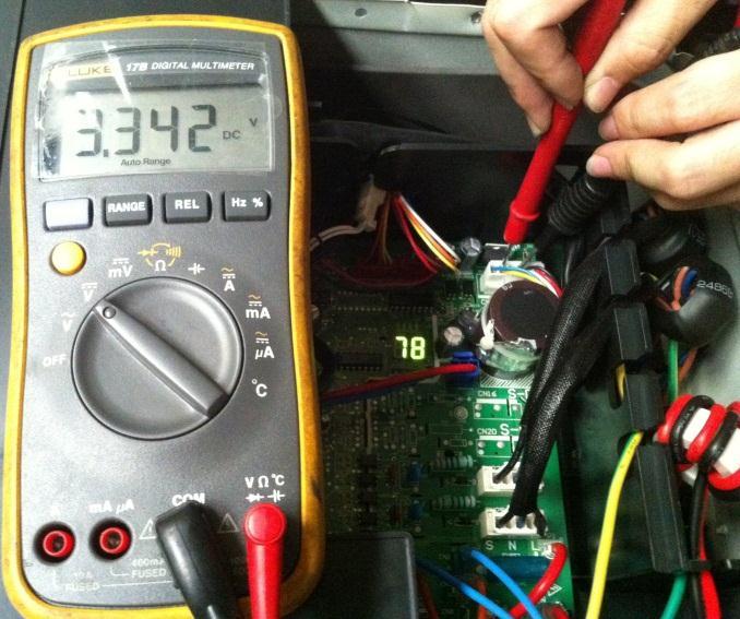
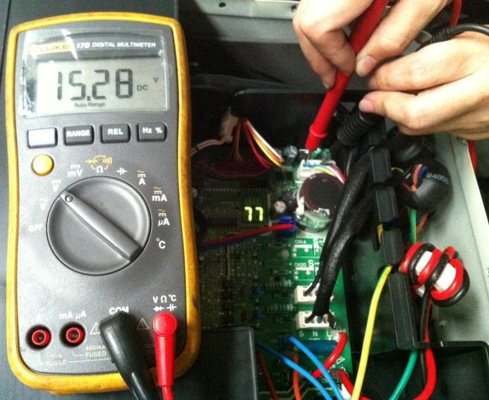
30 Remark: Use a multimeter to test the DC voltage between black pin and white pin of signal wire The normal value should be around 5V. Use a multimeter to test the DC voltage between black pin and red pin of signal wire. The normal value should be around 12V.

31 E4(open or short circuit of outdoor temperature sensor) diagnosis and solution F1/F2/F3/F4/F5 (open or short circuit of indoor coil temperature sensor) diagnosis and solution.. Error Code E4/F1/F2/F3/F4/F5 Malfunction decision conditions Supposed causes If the sampling voltage is lower than 0.06V or higher than 4.94V, the LED will display the failure. Wiring mistake Sensor faulty PCB faulty Trouble shooting: Check the connections between temperature sensor and PCB. Are the connections good? Correct the connections. Check the resistance value of the sensor via Appendix 1 and Appendix 2 Is it normal? Replace indoor or outdoor PCB. Replace the sensor
32 E5 (Voltage protection) error diagnosis and solution. Error Code Malfunction decision conditions Supposed causes Trouble shooting: E5 An abnormal voltage rise or drop is detected by checking the specified voltage detection circuit. Power supply problems. System leakage or block PCB faulty Voltage protection Check the voltage of outdoor unit power supply, whether the voltage between L(L1) and N (L2) is about 187~253VAC Check the power supply Check whether the voltage of IPM board P and N is normal? DC V for 18-27KBtu/h; DC V for 36KBtu/h Replace bridge rectifiers, and then check whether the system can run normally(only for quazone) Replace IPM board, and then check whether the system can run normally Replace outdoor main board Trouble is solved
33 IPM (for dual/trizone) IPM (for quazone) P-N (for dual/tri-zone)
")
34 P-N (for qua-zone)
 qua-zone)")
35 bridge rectifier (for dual/tri-zone) bridge rectifier (for qua-zone)

36 Remark: Measure the DC voltage between + and - port. The normal value should be 190V~250V.
37 E6 (PFC module protection) error diagnosis and solution. (For C3OE-36HFN1-M and C5OE-48HFN1-M) Error Code E6 Malfunction decision conditions Supposed causes Trouble shooting: When the voltage signal that PFC sends to main control board is abnormal, the display LED will show E6 and AC will turn off. Wiring mistake Outdoor PCB faulty Inductance of PFC module faulty PFC module malfunction PFC module protection Check whether the connecting line between main board and the PFC module is connected tightly Connect it tightly, check normal or not Check whether the voltage range of P-N on IPM module is normal? DC V for 18-27KBtu/h; DC V for 36KBtu/h Replace the outdoor main board Check whether the inductance of PFC module is good? If the inductance is good, the resistance of the two ports is 0 Replace the inductance Replace the PFC module Trouble is solved
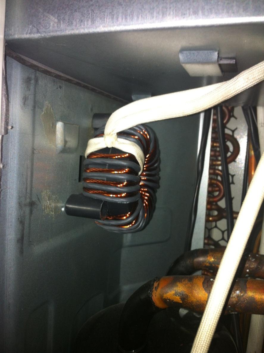
38 Inductance Two ports of the inductance
39
40 E8 (Outdoor fan speed has been out of control) diagnosis and solution Error Code E8 Malfunction decision conditions Supposed causes Trouble shooting: When outdoor fan speed keeps too low (300RPM) or too high(2400rpm) for certain time, the unit will stop and the LED will display the failure. Wiring mistake Fan ass y faulty Fan motor faulty PCB faulty Power off, then restart the unit 3 minutes later. Is it still displaying the error code? The unit operates normally. Shut off the power supply, rotate the fan by hand. Does it rotate properly? Find out the cause and have it solved. For example, whether the fan is blocked or the screws which fix the fan are tighten. Check the wiring of fan motor. Are all the connections good? Correct the connections. Check whether the main PCB is normal through index 1? Replace the main PCB Replace the fan motor Index 1:


41 1. DC fan motor(control chip is inside fan motor) Power on and when the unit is in standby, measure the voltage of pin1-pin3, pin4-pin3 in fan motor connector. If the value of the voltage is not in the range showing in below table, the PCB must have problems and need to be replaced. DC motor voltage input and output NO. Color Signal Voltage 1 Red Vs/Vm 200~380V Black GND 0V 4 White Vcc 13.5~16.5V 5 Yellow Vsp 0~6.5V 6 Blue FG 13.5~16.5V Vs Vcc Vsp FG
42
43 P0 (Temperature protection of compressor top) error diagnosis and solution. Error Code Malfunction decision conditions Supposed causes Trouble shooting: P0 If the sampling voltage is not 5V, the LED will display the failure. Wiring mistake Over load protector faulty System block Outdoor PCB faulty Temperature protection of compressor top Check the air flow system of indoor and outdoor units Clear up the air inlet and outlet or the heat exchanger of indoor and outdoor units. Power off, then restart the unit 10 minutes later Check whether the temperature of compressor top is more than 100 Check wiring connection of the overload protector Correct the connection. Check the refrigerant volume charge Measure the resistance between the two ports of the OLP. Is it zero? Replace the OLP. Replace the outdoor main PCB. Refrigerant system is blocked, such as capillary or welded point of pipes. Recharge the correct refrigerant volume.
44
45 P1 (High pressure protection) error diagnosis and solution. Error Code Malfunction decision conditions Supposed causes Trouble shooting: P1 If the sampling voltage is not 5V, the LED will display the failure. Wiring mistake Over load protector faulty System block Outdoor PCB faulty
46 High pressure protection Whether the wiring between the high pressure switch and main control board is connected well or correctly Connect it well Whether the high pressure protector is broken Method: Disconnect the plug. Measure the resistance of the high pressure protector, if the protector is normal the value is o, Replace high pressure protector Check whether the outdoor ambient temperature is higher than 50 Stop the unit Check if the outdoor unit ventilation is good NO Make the outdoor unit ventilate well Check if the outdoor fan runs properly please refer to the solution of fan speed has been out of control malfunction. Find out the cause and have it solved. Check whether the heat exchanger is dirty Clean the heat exchanger Replace outdoor main board Check whether the refrigerant system is ok
47
48 P2 (Low pressure protection) error diagnosis and solution. Error Code Malfunction decision conditions Supposed causes Trouble shooting: P2 If the sampling voltage is not 5V, the LED will display the failure. Wiring mistake Over load protector faulty System block Outdoor PCB faulty
49 Low pressure protection Whether the wiring between the low pressure protector and main control board is connected well or correctly Connect it well Whether the low pressure protector is broken Method: Disconnect the plug. Measure the resistance of the low pressure protector. If the protector is normal the value is o Replace low pressure protector Check whether the outdoor ambient temperature is too low Stop the unit Check whether valve core of high pressure valve is opened Check if if the indoor fan runs properly in cooling mode Open fully valve core of high pressure valve please refer to the solution of fan speed has been out of control malfunction. Find out the cause and have it solved. Replace outdoor main board Refrigerant is not enough add the refrigerant Check whether the refrigerant system is ok
50
51 P3 (Current protection of compressor) error diagnosis and solution. Error Code Malfunction decision conditions Supposed causes Trouble shooting: P3 If the outdoor current exceeds the current limit value, the LED will display the failure. Wiring mistake Over load protector faulty System block Outdoor PCB faulty Current protection of compressor Judge 1: Check whether the input current of the power supply wire is more than 12.5A(18K) (For 27K, it is 17.For 30K, it is 18.5.For 36K, it is 23A) Replace outdoor main board Check whether the refrigerant system is ok Judge 2: Check whether the outdoor ambient temperature is higher than 50 Stop the unit Judge 3: Check whether the outdoor unit is bad ventilation Make the outdoor unit ventilate well Judge 4: Check whether the heat exchanger is dirty Clean the heat exchanger Judge 5: The refrigerant pipe is blocked Let the refrigerant out, then use the high pressure nitrogen or refrigerant to blow pipe, vacuumize and charge the refrigerant again Replace outdoor main board,and check whether the system can run normally Replace the electric control box Trouble is solved
52
53 P4 (Temperature protection of compressor discharge) error diagnosis and solution. Error Code Malfunction decision conditions Supposed causes Trouble shooting: P4 When the compressor discharge temperature(t5) is more than 115 for 10 seconds, the compressor will stop and restart till T5 is less than 90. Refrigerant leakage Wiring mistake The discharge temperature sensor faulty Outdoor PCB faulty Temperature protection of compressor discharge Check whether the compressor discharge temp. is more than 115 C? Check whether the refrigerant is leak Stop leaking and add refrigerant Check whether the connection is right between compressor discharge temp. sensor and PCB according to wiring diagrams? Correct the wiring connection Measure the resistance value of compressor discharge temp. sensor. If the value is not normal is normal refer to the Appendix 2? Replace the compressor discharge temp. sensor Replace outdoor main PCB Replace high pressure valve assy
54 P5 (High temperature protection of condenser) error diagnosis and solution. Error Code Malfunction decision conditions Supposed causes Trouble shooting: P5 When outdoor pipe temperature is more than 65 C, the unit will stop, and unit runs again when outdoor pipe temperature is less than 52 C The condenser temperature sensor faulty Heat exchanger dirty System block High temperature protection of condenser Check the connection between temperature sensor and PCB. Correct the connection Check whether the condenser temperature is Higher than 65 C Check whether the resistance of condenser temp. sensor is normal refer to the Appendix 1 Replace the temperature sensor Check whether the outdoor ambient temperature is higher than 50 Stop the unit Check if the outdoor unit ventilation is good Make the outdoor unit ventilate well Check if the outdoor fan runs properly please refer to the solution of fan speed has been out of control malfunction. Find out the cause and have it solved. Check whether the heat exchanger is dirty Clean the heat exchanger Replace outdoor main board Refrigerant is not enough add the refrigerant Check whether the refrigerant system is ok
55 P6 (IPM module protection) error diagnosis and solution. Error Code Malfunction decision conditions Supposed causes Trouble shooting: P6 When the voltage signal that IPM send to compressor drive chip is abnormal, the display LED will show P6 and AC will turn off. Wiring mistake IPM malfunction Outdoor fan ass y faulty Compressor malfunction Outdoor PCB faulty
56 IPM module protection Check whether the voltage range of P-N on IPM module is normal? DC V for 18-27KBtu/h; DC V for 36KBtu/h Check whether the input power supply is correct? V, 1N, 60Hz Regulate it to correct, then check whether the system can work normally? Check whether the connecting line between main board and the IPM module is connected tightly Connect it tightly, check ok or not? Check whether the power supply line is connected correctly and tightly Connect it correctly and tightly, check ok or not? Check whether the connecting line of the compressor is connected correctly or tightly Connect it well, check ok or not? Check whether the lines in E-part box are connected tightly Connect it tightly, check ok or not? Replace the IPM module, check whether the system can work normally? Check if the outdoor fan runs properly or the outdoor unit ventilation is good. For KSIM30912-H216 (1G), please refer to 8.5 Trouble Criterion Of Main Parts, check whether the resistance of the fan motor is normal. If not, replace the fan motor. For other models, refer to the solution of fan speed has been out of control malfunction. Find out the cause and have it solved. Check whether the bridge rectifiers are normal? Use the multimeter to measure the resistance between each two terminals, check whether there is the condition that value of resistance is 0 Check whether the connecting line of every reactor is normal? If the line is broken, the resistance of the two ports is (models except for KSIM40912-H216 (2G));Check whether the PFC module broken (for KSIM40912-H216 (2G)) Replace the bridge rectifiers Replace the main board; check whether the system can work normally? Replace the connecting line or reactor or replace the PFC module(for M4OC-36HRFN1-M) Replace the compressor, check whether the system can work normally? Trouble is solved


57 The cooling operation or heating operation does not operate. Supposed causes 4-way valve faulty Check of 4-way, please refer to part 5 in 9.5 Trouble Criterion Of Main Parts When cooling, heat exchanger of non-operating indoor unit frosts. When heating, non-operating indoor unit get warm. Supposed causes EXV faulty Wire and tubing connected in reverse. Check of EXV, please refer to part 6 in 9.5 Trouble Criterion Of Main Parts. tice: If you replace outdoor main PCB of KSIM30912-H216 (1G), you need to check whether the PCB is produced before Apr If yes, you need to short connect OLP connector., Otherwise, the outdoor LED will show P0.
58 8.5 Trouble Criterion Of Main Parts. Spec. Indoor unit Model 9k Oasis 12k Oasis 18k Oasis 24k Oasis Indoor fan motor WZDK20-38G WZDK20-38G WZDK58-38G WZDK60-38G Model KDIR09-H2 KDIR12-H2 KDIR18-H2 KDIR24-H2 Indoor fan motor WZDK55-38GS-W WZDK55-38GS-W WZDK90-38GS-W WZDK90-38GS-W Model KTIR09-H2 KTIR12-H2 KTIR18-H2 Indoor fan motor WZDK46-38G WZDK46-38G WZDK46-38G Model KFIR09-H2 KFIR12-H2 Indoor fan motor RD A RD A
59 The Klimaire logo is a registered Trademark of Klimaire Products inc. Copyright 2016 Klimaire Products Inc NW 89 Place, Doral, FL USA Tel: (305) Fax (305) sales@klimaire.com The design and specifications are subject to change without prior notice for product improvement. Consult with the sales agency or manufacturer for details.
troubleshooting Outdoor Unit: KSIE009-H221-O, KSIE012-H220-O, KSIE018-H220-O KSIE024-H220-O, KSIR036-H218, KSIR048-H218
 troubleshooting Table of Contents 1. Troubleshooting Model Numbers: Indoor Unit: KDIR09-H2, KTIR09-H2, KUIR09-H2 KDIR12-H2; KTIR12-H2, KUIR12-H2 KDIR18-H2, KTIR18-H2, KUIR18-H2 KDIR24-H2, KTIR24-H2, KUIR24-H2
QUARTZ INVERTER TROUBLESHOOTING GUIDE
 QUARTZ INVERTER TROUBLESHOOTING GUIDE QIN415H2V31 QIN618H2V31 QIN721H2V31 QIN1129H2V31 INVERTER MINI SPLIT SYSTEM WARNING The information contained in the manual is intended for use by a qualified service
KSID MINI Split DC Inverter QUICK CONNECT Air Conditioner TROUBLESHOOTING KSID016-H215Q. Model Numbers:
 KSID MINI Split DC Inverter QUICK CONNECT Air Conditioner TROUBLESHOOTING Model Numbers: KSID012-H115Q KSID022-H215Q KSID016-H215Q WARNING Installation MUST conform with local building codes or, in the
LIGHT COMMERCIAL. Troublesooting
 LIGHT COMMERCIAL Troublesooting 2. 2.1 Display board 2.1.1 Icon explanation on indoor display board (Super slim cassette 24K). 2.1.2 Icon explanation on indoor display board (Compact cassette 12K, 18K).
SERVICE MANUAL Room Air Conditioner DC Inverter Multi Split Outdoor units
 SERVICE MANUAL Room Air Conditioner DC Inverter Multi Split Outdoor units FS2MIF-141AE2 FS2MIF-181AE2 FS3MIF-211AE2 FS3MIF-271AE2 FS4MIF-281AE2 FS4MIF-361AE2 FS5MIF-421AE0 NOTE: Before servicing the unit,
GAMA DOMÉSTICA MULTISPLIT Manual de Servicio
 GAMA DOMÉSTICA MULTISPLIT Manual de Servicio CONTENTS 1. General information of Outdoor Units... 2 2. Features... 3 3. Dimensions... 4 4. Refrigeration Cycle Diagram... 5 5. Wiring diagram... 7 6. Indoor
SERVICE MANUAL MIDEA AIRCONDITIONER EUROPE MARKET SUPER DC INVERTER MULTI TYPE
 SERVICE MANUAL MIDEA AIRCONDITIONER EUROPE MARKET SUPER DC INVERTER MULTI TYPE M2OE-14HFN1-Q M2OF-18HFN1-Q M3OE-21HFN1-Q M3OE-27HFN1-Q M4OE-28HFN1-Q M4OB-36HFN1-Q M5OE-42HFN1-Q DC MULTI OUTDOOR UNITS CONTENTS
SERVICE MANUAL MIDEA AIRCONDITIONER SUPER DC INVERTER MULTI TYPE OUTDOOR UNITS
 SERVICE MANUAL MIDEA AIRCONDITIONER SUPER DC INVERTER MULTI TYPE OUTDOOR UNITS M2OE-14HFN1-Q M2OF-18HFN1-Q M3OE-21HFN1-Q M3OE-27HFN1-Q M4OE-28HFN1-Q M4OB-36HFN1-Q M5OE-42HFN1-Q Service manual CONTENTS
SERVICE MANUAL MIDEA SUPER DC INVERTER MULTI TYPE DC MULTI OUTDOOR UNITS
 SERVICE MANUAL MIDEA SUPER DC INVERTER MULTI TYPE DC MULTI OUTDOOR UNITS M2OD-16HFN1-Q M2OD-18HFN1-Q M3OD-21HFN1-Q M3OD-26HFN1-Q M4OD-28HFN1-Q M4OA-36HFN1-Q M5OC-36HFN1-Q M5OD-42HFN1-Q CONTENTS 1. GENERAL
PART7. Trouble Shooting
 PART7. Trouble Shooting 1. Indoor Unit Error Display Display E0 E1 E2 E3 E5 LED STATUS EEPROM parameter error Indoor unit and outdoor unit communication protection Zero-crossing signal error Indoor fan
BRIVIS DUCTED INVERTER SERVICE MANUAL DRCi
 BRIVIS DUCTED INVERTER SERVICE MANUAL DRCi 1 TABLE OF CONTENTS TABLE OF CONTENTS... 2 IMPORTANT NOTE... 3 FAULT FINDING AND DIAGNOSTICS... 3 ABBREVIATIONS... 3 PCB S... 4 OUTDOOR MAIN PCB... 4 INDOOR PCB...
LUV INVERTER SERIES. Self-diagnostics and Trouble-shooting. Part 2 of 2 42/38LUV028H 42/38LUV035H 42/38LUV052H 42/38LUV065H 42/38LUV070H 42/38LUV080H
 LUV INVERTER SERIES Part 2 of 2 Self-diagnostics and Trouble-shooting 42/38LUV028H 42/38LUV035H 42/38LUV052H 42/38LUV065H 42/38LUV070H 42/38LUV080H MAJOR COMPONENT CHECKING COMPRESSOR Use a multi-meter
Service Manual. 9. Maintenance. 9.1 Precautions before Maintenance. discharge resistance or plug of soldering iron. Installation and Maintenance
 9. Maintenance 9.1 Precautions before Maintenance Service Manual pacitor after power off. - discharge resistance or plug of soldering iron A B A B - nance safely. 40 9.2 Error Code List O. 1 2 3 4 5 6
9. Maintenance. 9.1 Precautions before Maintenance. Service Manual. electrolytic capacitor after power off. maintenance safely.
 9. Maintenance 9.1 Precautions before Maintenance electrolytic capacitor after power off. A B A B maintenance safely. 50 9.2 Error Code List Unit o. ame Display 8 nixie 0.5s) Operation Indicator Cool Indicator
Fault Codes. J control
 J control Timer Temp Fault Codes 12 11 10 9 8 7 6 5 4 3 2 1 30 29 28 27 26 25 24 23 22 21 20 Enter unit inspection mode by pushing the UP and DOWN buttons simultaneously for two seconds. Ensure that the
No Operation of air conditioner Explanation
 12. Troubleshooting 12-1 Items to be checked first 1. The input voltage should be rating voltage ±10% range. The air conditioner may not operate properly if the voltage is out of this range. 2. Is the
6. Troubleshooting. 6-1 Basic items for trouble shooting. Samsung Electronics 17
 6. Troubleshooting Since the inverter air conditioner is equipped with Electrical control circuits at both Indoor & outdoor unit, the trouble shooting shall be performed according to the error mode. Inside
9. Maintenance. 9.1 Error Code List. Service Manual. Installation and Maintenance
 9. Maintenance 9.1 Error Code List o. ame Display Method of Outdoor Display Method of Indoor Unit Unit Indicator has 3 kinds of Indicator Display (during display status during Dual-8 ing, O 0.5s OFF ing,
Driftsinstruks. Utopia kontroller feilkoder PCP-2HTE og PC-ART. Vi håper de får stor glede av et Novema kulde produkt!
 Driftsinstruks Utopia kontroller feilkoder PCP-2HTE og PC-ART Vi håper de får stor glede av et vema kulde produkt! www.novemakulde.no 8/14 TROUBLESHOOTING 8.2. TROUBLESHOOTING PROCEDURE 8.2.1. ALARM CODE
LG Air Conditioning Universal & Multi Split Fault Codes Sheet. Universal and Multi Split Units
 Universal and Multi Split Units If there is a fault on any LG Universal or Multi unit, a two digit number will appear on the remote controllers led display. If the unit does not have a remote controller
12. Troubleshooting Items to be checked first. Samsung Electronics
 12. Troubleshooting 12-1 Items to be checked first 1. The input voltage should be rating voltage ±10% range. The air conditioner may not operate properly if the voltage is out of this range. 2. Is the
SPLIT TYPE ROOM AIR CONDITIONER WALL MOUNTED TYPE
 SPLIT TYPE ROOM AIR CONDITIONER WALL MOUNTED TYPE Indoor unit ASYA24LCC ASYA24LCC ASYA24LCC Outdoor unit AOYR24LCC AOYR24LCD AOYR24LCL CONTENTS SPECIFICATIONS..................1 DIMENSIONS.....................
SPLIT TYPE ROOM AIR CONDITIONER. WALL MOUNTEDtype INVERTER. Models Indoor unit Outdoor unit AOU18RLXFW AOU24RLXFW ASU18RLF ASU24RLF R410A
 SERVICE INSTRUCTION SPLIT TYPE ROOM AIR CONDITIONER WALL MOUNTEDtype INVERTER Models Indoor unit Outdoor unit ASU18RLF ASU24RLF AOU18RLXFW AOU24RLXFW R410A CONTENTS 1. DESCRIPTION OF EACH CONTROL OPERATION
WALL MOUNTED type SPLIT TYPE ROOM AIR CONDITIONER. Models
 SPLIT TYPE ROOM AIR CONDITIONER WALL MOUNTED type Models Indoor unit ASH9LSACW ASH12LSACW Outdoor unit AOH9LSAC AOH12LSAC CONTENTS SPECIFICATIONS...................... 1 DIMENSIONS..........................
4.Failure phenomenon. Mirage comes out from indoor. When the cold air from AC cools the indoor air. unit
 4.Failure phenomenon Phenomenon Mirage comes out from indoor unit Noise Sometimes, the room is smelly when heating, there is no wind at the beginning of starting unit Causing explanation When the cold
SERVICE MANUAL FREE COMBI SERIES FC-E24AI, FC-E28AI
 SERVICE MANUAL FREE COMBI SERIES FC-E24AI, FC-E28AI 1.Technical specifications Model Compressor Manufacturer/trademark Compressor Model Compressor Type L.R.A. (A) Compressor RLA(A) Compressor Power Input(W)
3. SERVICE TOOLS Inverter checker RSUK09-17 CLIMATE COMFORT. All Seasons. Heating. Air Conditioning. Applied Systems.
 All Seasons CLIMATE COMFORT Heating 3. SERVICE TOOLS 3.2. Inverter checker RSUK09-17 Air Conditioning Applied Systems Refrigeration 3.2. Inverter checker RSUK09-17: index 1. Outlook 2. How to connect?
LG Air conditioning CAC and Multi Split unit Fault code sheet Universal and Multi Split Units
 Universal and Multi Split Units If there is fault on any LG universal or multi unit a two digit number will appear on the remote controllers led display. If the unit does not have a remote controller the
HP21 SERVICE SUPPLEMENT UNIT INFORMATION. TSC6 Two-Speed Control
 SERVICE UNIT INFORMATION SUPPLEMENT HP21 Corp. 9426 L10 Litho U.S.A. All HP21-4 and -5 units (single and three phase) are equipped with a TSC6 two-speed control. The TSC6 (A14) two-speed control contains
AIR CONDITIONER SECTION AC CONTENTS AUTO
 AIR CONDITIONER SECTION AC CONTENTS AUTO PRECAUTIONS AND PREPARATION SRS Airbag Pretensioner Seatbelt... 4 A/C Refrigerant HFC134a Handling... 4 Compressor Oil... 4 Tube Connection... 4 O-Ring Part Number...
YN018GMFI16M2D-V V~ 60Hz 1Phase Serials: PRE
 Sale model: ProdCode: YN018GMFI16M2D-V1 220057000460 208-230V~ 60Hz 1Phase PRE 50130047 No. Part Name Quantity BOM code Bin Code Remark 1 Rear net 1 2011481G0001 8 2 Ambient temperature sensor assembly
Phoenix Inverter
 Manual EN Handleiding NL Manuel FR Anleitung DE Manual ES Appendix Phoenix Inverter 12 250 12 375 12 500 12 800 24 250 24 375 24 500 24 800 48 250 48 375 48 500 48 800 1. Safety instructions WARNING: ELECTRIC
Part 2 Functional Description
 ESIE06-0 Part Functional Description What is in this part? This part contains information on the functions used to control the system. Understanding these functions is vital when diagnosing a malfunction
Parts Lists. Forward Series. Rev. Feb. 2017
 s HSU09VHJ(DB)-G / HSU09VHJ(DB)-W HSU12VHJ(DB)-G / HSU12VHJ(DB)-W HSU18VHJ(DB)-G / HSU18VHJ(DB)-W HSU24VHJ(DB)-G / HSU24VHJ(DB)-W 1800 Valley Road Wayne, NJ 07470 Tel +973.617.1800 www.haier.com - Edition
INSTALLATION AND MAINTENANCE
 ISTALLATIO AD MAITEACE TROUBLESHOOTIG Content: 1. Precautions before Performing Inspection or Repair 2. Confirmation 3. Flashing LED of Indoor/Outdoor Unit and Primary Judgement 4. How to Check Simply
MPPT Solar Integrated Inverters (500VA~2500VA) User Manual THE SOLAR TECH CO.,LTD. Solar Integrated Inverter Series 500VA~2500VA 13.
 User Manual THE SOLAR TECH CO.,LTD. Solar Integrated Inverter Series 500VA~2500VA 13.") MPPT Solar Integrated Inverters (500VA~2500VA) User Manual THE SOLAR TECH CO.,LTD. - 1 - Table of Contents 1. SALIENT FEATURES...3 2.. PRODUCT INSTALLATION & PRECAUTIONS...3 2.1. PRODUCT INSTALLATION &
MPPT Solar Integrated Inverters (500VA~2500VA) User Manual THE SOLAR TECH CO.,LTD. - 1 - Table of Contents 1. SALIENT FEATURES...3 2.. PRODUCT INSTALLATION & PRECAUTIONS...3 2.1. PRODUCT INSTALLATION &
ACCESSORY KIT INSTALLATION INSTRUCTIONS
 ACCESSORY KIT INSTALLATION INSTRUCTIONS Low Ambient Accessory For Air Cooled Split-System Air Conditioners YD360/480/600, YJ-30/-40/-50 and J30/40/50 YD Models 642546-UAI-A-080 GENERAL Standard operation
Technical Support Division GD CHIGO HEATING & VENTILATION EQUIPMENT CO., LTD.
 Technical Support Division 2012.10 1 1. External appearance 2. Nomenclature 3. Specifications 4. Dimensions 5. Service space 6. Piping diagram 7. Wiring diagram 8. Capacity tables 9. Electric characteristics
SPLIT TYPE ROOM AIR CONDITIONER FLOOR TYPE
 SPLIT TYPE ROOM AIR CONDITIONER FLOOR TYPE Indoor unit AGYF09LAC AGYFLAC AGYFLAC AGYFLAC Outdoor unit AOYV09LAC AOYVLAC AOYVLAC AOYVLAL CONTENTS SPECIFICATIONS..................... DIMENSIONS.........................
SECOND GENERATION Use this guide with unit serial number prefix beginning with BWF using Terra Power separator.
 Technical Information and Diagnostic Guide for SECOND GENERATION Use this guide with unit serial number prefix beginning with BWF using Terra Power separator. This guide will assist you in becoming more
HEATER & AIR CONDITIONING CONTROL SYSTEM
 VENTILATION, HEATER & AIR CONDITIONER SECTION HAC A HEATER & AIR CONDITIONING CONTROL SYSTEM B C D CONTENTS E WITH COLOR DISPLAY BASIC INSPECTION... 5 INSPECTION AND ADJUSTMENT... 5 Operational Check (Front)...5
Outdoor UPS. User Manual. Contents. Please read carefully this manual before installing and using this product. 1 Introduction Safety...
 Contents 1 Introduction...1 2 Safety...4 3 Product Specifications...6 Outdoor UPS User Manual 4 Installation...8 4.1 Inspection...8 4.2 Installing the UPS Cabinet...8 4.3 Connecting the Power Supply...10
ZIP Economizer Fault Detection and Diagnostics (FDD) Table
 Table") Fault Detection and Diagnostics (FDD) Table Fault Detection Problem Diagnostic ction (in addition to alarm stored / transmitted) Potential Cause C Fault Code OT sensor predetermined range O damper returns
Fault Detection and Diagnostics (FDD) Table Fault Detection Problem Diagnostic ction (in addition to alarm stored / transmitted) Potential Cause C Fault Code OT sensor predetermined range O damper returns
Subject Underhood G System Error Codes and Symptoms System or Parts affected
 System or Parts affected Index Underhood70G (V90Gxxx) System or Parts affected... 1 Overview... 1 Identifying your System... 1 Retrieving Logged Error Messages... 1 Error Messages... 3 Error Message Table...
Users Manual. Defender 1 8.0KW to 14.0KW Online Emergency Lighting Inverter. Technical Manual # Revision B
 Users Manual Defender 1 8.0KW to 14.0KW Online Lighting Inverter Technical Manual #018-0102-01 Revision B Phone: 1.877.DSPM.POWER 1.877.377.6769 Fax: 909.930.3335 Website: www.dspmanufacturing.com E-Mail:
NB NB 1511 NB NB 4031 TRUE ON-LINE DOUBLE CONVERSION UPS
 NB 0811 - NB 1511 NB 0831 - NB 4031 TRUE ON-LINE DOUBLE CONVERSION UPS LEN.MAN.UPS.069 Rev.2.00/2002 CONTENTS Safety Instructions 1 Introduction 3 2.1 FEATURE 3 2.2 UPS modules 4 How the UPS works 5 3.1
YN012GMFI16RUD Decription: Model Number: Product Code: Power Supply:
 YN012GMFI16RUD 220037506240 1 Ambient temperature sensor assembly 1 202301310063 4 2 Rear net 1 201237490045 5 3 Condenser assembly 1 201537490008 617 4 Pipe temperature sensor assembly 1 202440500004
Heat Recovery Ventilation
 .book Page i Thursday, March 30, 2000 3:31 PM Heat Recovery Ventilation VAM 500EJ VAM 800EJ VAM1000EJ VAM2000EJ VAM500~1000EJ VAM2000EJ Table of Contents i .book Page ii Thursday, March 30, 2000 3:31 PM
MANUAL CONTROL / SEMIAUTO TEMPERATURE CONTROL HEATING, VENTILATION AND AIR CONDITIONING SYSTEM
 SECTION 7C MANUAL CONTROL / SEMIAUTO TEMPERATURE CONTROL HEATING, VENTILATION AND AIR CONDITIONING SYSTEM CAUTION: Disconnect the negative battery cable before removing or installing any electrical unit
5. TROUBLE DIAGNOSIS
 . TROBLE DIAGNOSIS -1. Contents of Remote Controller Switch Alarm Display... -2-2. Outdoor nit Control anel LED Display... -4-3. AC System Alarm Codes... - -4. Inspection of arts (Outdoor nit)... -68 -.
 Page 1 of 50 Section 412-00: Climate Control System General Information DIAGSIS AND TESTING 1997 Mark VIII Workshop Manual Climate Control System Special Service Tool(s) 73 Digital Multimeter 105-R0051
ENGINE 01 02A 1. Toc of SCT ON-BOARD DIAGNOSTIC [ENGINE. Toc of SCT 01 02A ON-BOARD DIAGNOSTIC [ENGINE CONTROL SYSTEM (ZM)] 01 02A
![ENGINE 01 02A 1. Toc of SCT ON-BOARD DIAGNOSTIC [ENGINE. Toc of SCT 01 02A ON-BOARD DIAGNOSTIC [ENGINE CONTROL SYSTEM (ZM)] 01 02A](/thumbs/90/103285807.jpg "ENGINE 01 02A 1. Toc of SCT ON-BOARD DIAGNOSTIC [ENGINE. Toc of SCT 01 02A ON-BOARD DIAGNOSTIC [ENGINE CONTROL SYSTEM (ZM)] 01 02A") ENGINE 01 SECTION Toc of SCT ON-BOARD DIAGNOSTIC [ENGINE CONTROL SYSTEM (ZM)]...01-02A ON-BOARD DIAGNOSTIC [ENGINE CONTROL SYSTEM (FS)]...01-02B ON-BOARD DIAGNOSTIC [CRUISE CONTROL SYSTEM].......01-02C
ENGINE 01 SECTION Toc of SCT ON-BOARD DIAGNOSTIC [ENGINE CONTROL SYSTEM (ZM)]...01-02A ON-BOARD DIAGNOSTIC [ENGINE CONTROL SYSTEM (FS)]...01-02B ON-BOARD DIAGNOSTIC [CRUISE CONTROL SYSTEM].......01-02C
Uninterruptible Power System
 USER'S MANUAL Emergency Backup Power Supply For Use With Computer Loads Only Power Surge/Noise Protection Intelligent Auto-Shutdown Software Internet Line Protection Cost Efficiency UPS 1 st Edition Uninterruptible
 Pagina 1 di 1 INSPECTION In-car air sensor is located at crash pad. It is installed with humidity sensor. It will detect interior, which will be used for discharge control, sensor failsafe, door control,
01 02B ON-BOARD DIAGNOSTIC [ENGINE CONTROL SYSTEM (FS)]
![01 02B ON-BOARD DIAGNOSTIC [ENGINE CONTROL SYSTEM (FS)]](/thumbs/80/80600627.jpg "01 02B ON-BOARD DIAGNOSTIC [ENGINE CONTROL SYSTEM (FS)]") ON-BOARD DIAGNOSTIC [ENGINE CONTROL SYSTEM (FS)] CONTROL SYSTEM WIRING DIAGRAM [FS]............................ 2 CONTROL SYSTEM DEVICE AND CONTROL RELATIONSHIP CHART [FS]........ 4 Engine Control System............
ON-BOARD DIAGNOSTIC [ENGINE CONTROL SYSTEM (FS)] CONTROL SYSTEM WIRING DIAGRAM [FS]............................ 2 CONTROL SYSTEM DEVICE AND CONTROL RELATIONSHIP CHART [FS]........ 4 Engine Control System............
Technical Information and Diagnostic Guide
 Technical Information and Diagnostic Guide This guide will assist you in becoming more familiar with the working components of the NITE System and the proper steps and procedures to completely diagnose
A/C SYSTEM GENERAL DIAGNOSTIC PROCEDURES
 Article Text ARTICLE BEGINNING 1993 AIR CONDITIONING & HEAT A/C General Diagnostic Procedures Diagnosis is an important first step in A/C system servicing. To save time and effort, systems should be carefully
A/C-HEATER SYSTEM - AUTOMATIC
 A/C-HEATER SYSTEM - AUTOMATIC 1988 Toyota Celica 1988 Automatic A/C-Heater Systems Celica * PLEASE READ THIS FIRST * CAUTION: When discharging air conditioning system, use only approved refrigerant recovery/recycling
Users Manual. Cobra Plus Stand-By Emergency Lighting Inverter. Technical Manual # Revision B
 Users Manual Cobra Plus Stand-By Lighting Inverter Technical Manual #018-0110-01 Revision B Phone: 1.877.DSPM.POWER 1.877.377.6769 Fax: 909.930.3335 Website: www.dspmanufacturing.com E-Mail: techsupport@dspmanufacturing.com
ASU18RLB ASU24RLB AOU18RLB AOU24RLB SPLIT TYPE ROOM AIR CONDITIONER WALL MOUNTED TYPE CONTENTS
 SPLIT TYPE ROOM AIR CONDITIONER WALL MOUNTED TYPE Indoor unit ASU8RL ASURL Outdoor unit AOU8RL AOURL CONTENTS SPECIFICATIONS................... DIMENSIONS...................... REFRIGERANT SYSTEM DIAGRAM....
TECHNICAL MANUAL 2013 CONSOLE MULTI DC INVERTER
 TECHNICAL MANUAL 2013 CONSOLE MULTI DC INVERTER MODELS Indoor units BCODM26A2 BCODM36A2 BCODM53A2 Outdoor units BD2M53A3 BD3M98A3 BD4M114A3 BD5M120A3 This manual has been created for informative purpose.
SERVICE INSTRUCTION R410A. SPLIT TYPE ROOM AIR CONDITIONER Compact Wall Mounted Wall Mounted / Floor Compact Cassette / Slim Duct INVERTER MULTI
 SPLIT TYPE ROOM AIR CONDITIONER Compact Wall Mounted Wall Mounted / Floor Compact Cassette / Slim Duct INVERTER MULTI SERVICE INSTRUCTION Models Indoor unit Outdoor unit ASU7RLF ASU9RLF ASU2RLF ASU8RLF
WALL MOUNTED type SPLIT TYPE ROOM AIR CONDITIONER ASY9USBCW AOY9UGBC ASY12USBCW AOY12UGBC. Models Indoor unit Outdoor unit
 SPLIT TYPE ROOM AIR CONDITIONER WALL MOUNTED type Models Indoor unit Outdoor unit ASY9USBCW AOY9UGBC ASY12USBCW AOY12UGBC CONTENTS SPECIFICATIONS....................... 1 OUTLINE AND DIMENSIONS............
Horizon Troubleshooting Flowchart
 Horizon Troubleshooting Flowchart Table of Contents Warnings..................................................... 2 Screen........................................................3 Temp Sensor...................................................4
User Manual / Manuel utilisateur
 User Manual / Manuel utilisateur Inverter Charger / Convertisseur Chargeur English version...1 English Version 1 Table of Contents ABOUT THIS MANUAL... 3 Purpose... 3 Scope... 3 SAFETY INSTRUCTIONS...
Wiring diagrams on page 29 are for reference only. For detailed vehicle wiring refer to Navistar documents.
 1 10/2014 REV 7 !!Attention!! Before performing diagnostics: Wiring diagrams on page 29 are for reference only. For detailed vehicle wiring refer to Navistar documents. Check for Fault Codes using the
USER MANUAL MPS 1-5KW SERIES
 USER MANUAL MPS 1-5KW SERIES Low Series Frequency Solar and Wind Power Charging Inverter CONTENTS 1 WWW.NEXTGENNRG.COM 1. Introduction... 3 2. Profile Structure 4 2.1. Working Principle 4 2.2.Product Features..5
P445 Series Electronic Lube Oil Control
 FANs 125, 121 s Section P Product/Technical Bulletin P445 Issue Date 0100 P445 Series Electronic Lube Oil The P445 Series Electronic Lube Oil is designed for use on refrigeration compressors equipped with
PANASONIC FAULT CODE GUIDE. ECOi ECO-G - PACi
 PANASONIC FAULT CODE GUIDE ECOi ECO-G - PACi 1 Page INDEX P3 GHP ENGINE ISSUES P4 CENTRAL CONTROLLER ISSUES P5 ADDRESSING & COMMUNICATION PROBLEMS P6 SENSOR FAULTS P7 COMPRESSOR ISSUES P8 INCORRECT SETTINGS
Technical Support Division GD CHIGO HEATING & VENTILATION EQUIPMENT CO., LTD.
 Technical Support Division 2013.12 1 1. External appearance 2. Nomenclature 3. Specifications 4. Dimensions 5. Service space 6. Piping diagram 7. Wiring diagram 8. Capacity tables 9. Electric characteristics
Engineering Data Book
 40VMA Outside Air Processing Unit for Variable Refrigerant Flow (VRF) Systems Engineering Data Book Manufacturer reserves the right to discontinue, or change at any time, specifications or designs without
Application Engineering
 Application Engineering February, 2009 Copeland Digital Compressor Controller Introduction The Digital Compressor Controller is the electronics interface between the Copeland Scroll Digital Compressor
Table of Contents Foreword I. Product Introduction II. Notice For Safety III. Main Technical Parameters IV.
 Foreword Thank you for choosing the LGK-ID IGBT Digital Air Plasma Cutter of Delixi (Hangzhou) Inverter Co., Ltd. Before use LGK-ID IGBT Digital Air Plasma Cutter, please carefully read this Manual to
Electronic Ballast EVG 2000-T
 Electronic Ballast EVG 2000-T Operating Manual Table of contents 1 Description 1.1 Advantages of this ballast... 3 1.2 Functional principle... 3 1.3 Energization... 4 1.4 Visualization... 5 1.5 Indications
Technical Information and Diagnostic Guide RestStar Use this guide with 5700XE RestStar Unit. Western Star 5700XE.
 Western Star 5700XE RestStar 4 10-2017 1 Technical Information and Diagnostic Guide RestStar Use this guide with 5700XE RestStar Unit 2390 Blackhawk Road P.O. Box 6007 Rockford, IL 61125 nitesystem.com
Installation and Operating Instructions
 Installation and Operating Instructions Congratulations on your purchase of a Franklin Electric pump protection system. Pumptec-Plus is the most sophisticated pump protection system on market today. It
On Line UPS. LUC 1000E / LUC 2000E / LUC 3000E User Manual
 On Line UPS LUC 1000E / LUC 2000E / LUC 3000E User Manual Save This Manual Please read this manual carefully prior to storage, installation, wiring, operation and maintenance of the UPS. This manual contains
RAC Product Trouble Shooting Guide
 1 RAC Product Trouble Shooting Guide Model : Wall Mount Inverter Type CAUTION Make sure to fully read and understand the safety precautions described in the SVC manual before SVC. Only authorized personnel
Service Manual. Extractor Model XR28QP. For The. For: Troubleshooting Adjustments
 Service Manual For The X Ride 28 Rider Extractor Model XR28QP For: Training Troubleshooting Adjustments Contents 1 Cautions ------------------------------------------------------------------------------
4.2 Component Identification
 Digital Control Panels Deep Sea Electronics 5220 4.1 General 4.2 Component Identification 4.3 The YML5220 Controller 4.4 Description of Controls 4.5 Navigation 4.5.1 General Navigation 4.5.2 The Event
Engineering Data Book
 40VMH High Static Duct Indoor Unit for Variable Refrigerant Flow (VRF) Systems Engineering Data Book Manufacturer reserves the right to discontinue, or change at any time, specifications or designs without
Service Manual. For the SCV2832E, SCV2426, Automatic Scrubbers For: Training Troubleshooting
 Service Manual For the SCV2832E, SCV2426, SCV280000 & ES2832 Automatic Scrubbers For: Training Troubleshooting Adjustments Contents 1 Cautions ----------------------------------------------------------------------
Table of Contents. AMO series quantitative pressured centralized lubricating system 1. Illustration of AMO motor driven lubricating system 1
 Table of Contents AMO series quantitative pressured centralized lubricating system 1 Illustration of AMO motor driven lubricating system 1 AMO motor driven thin oil lubricating pump MO type pressured thin
Application Engineering
 Application Engineering March 2011 Copeland Digital Compressor Controller Introduction The Digital Compressor Controller is the electronics interface between the Copeland Scroll Digital compressor or the
Auto Idle System Trouble Shooting
 Kubota Construction Machinery Auto Idle System Trouble Shooting KX91-3, KX101-3, KX121-3, KX161-3, U35-3, U45-3 09.11.2004 d. Auto Idle(AI) version: Trouble diagnosis with lamp (1)General On the AI type
HPP1 MK5 Owner s Manual
 J Wolmarans Page 1 2016/09/15 Page 1 of 9 TABLE OF CONTENTS Page 1 Introduction...2 2 Models...2 3 Safety warnings...3 4 Contents...3 5 Installation...3 5.1 Mounting the unit:...3 5.2 Connecting the battery:...3
SERVICE MANUAL OUTDOOR UNIT. No. OB387
 SPLIT-TYPE, HEAT PUMP AIR CONDITIONERS Revision C: MUH-A25VB - E has been added. Please void OB87 REVISED EDITION-B. OUTDOOR UNIT SERVICE MANUAL HFC utilized R40A. OB87 REVISED EDITION-C Wireless type
Copeland Screw TM Compressors
 Copeland Screw TM Compressors Mechanical Guidelines for SHL & SHM Models using ESC-201 Control System Contents: Start-Up Procedure Operating Specifications Maintenance Trouble Shooting Guidelines Start-up
Installation and Operating Instructions
 PUMP PROTECTION SYSTEM Installation and Operating Instructions Congratulations on your purchase of a Franklin Electric pump protection system. Pumptec-Plus is the most sophisticated pump protection system
Duplex Booster System Instruction Manual
 Duplex Booster System Instruction Manual ISO 9001 Certified Walrus America Inc Congratulations on your purchase of Walrus IC Series Inverter Control System. Please read all instructions carefully before
User Manual Rittal PMC UPS 6kVA
 User Manual Rittal PMC UPS 6kVA Germany Rittal GmbH & Co. KG Auf dem Stützelberg D-35745 Herborn Tel.: ++49-27 72-5 05-0 Fax: ++49-27 72-5 05-23 19 Internet: www.rittal.de 26 Contents 1. Introduction...
Trouble Shooting a Jouan C/CR4.22 Centrifuge
 The world leader in serving science Trouble Shooting a Jouan C/CR4.22 Centrifuge No Spin Condition Erratic Speed Control No Cooling General Parts List Wiring Diagram No Spin Condition (Removing the Front
Engineering Data Book
 40VMM Medium Static Duct Indoor Unit for Variable Refrigerant Flow (VRF) Systems Engineering Data Book Manufacturer reserves the right to discontinue, or change at any time, specifications or designs without
SCC-MPPT Solar Charge Controller
 Solar Charge Controller Quick Guide 200W 300W 400W 600W 850W V. 2.2 1. Introduction solar charge controller uses PWM-based DSP controller to keep the batteries regulated and prevent batteries from overcharging
Two temperature sensors to protect against freezing and high head pressure in both the indoor evaporator and the outdoor condenser
 The ZC 107 Zone Control System was designed to provide the perfect comfort control within the home. At the same time it was designed to make an airconditioning system work more efficiently and thereby
Pure sine wave charger inverter Product Manual
 Pure sine wave charger inverter Product Manual The inverter installer must be professional, for the high pressure in the inverter, unprofessional person please do not open it. The inverter should be installed
CX-SERIES ADVANCED BATTERY CHARGER
 CX-SERIES ADVANCED BATTERY CHARGER Table of Content 1. IMPORTANT SAFETY INFORMATION... 2 1-1 General Safety Precautions... 2 1-2 Battery Precautions... 2 2. FEATURES... 3 2-1 Battery Charging Curve...
PANcharge1k Battery Charger User's Manual
 PANcharge1k Battery Charger User's Manual Ver.1.00E Table of Contents 1. Important Safety Instructions... 3 1-1 General Safety Precautions... 3 1-2 Battery Precautions... 3 1-3 Electromagnetic Disturbance...
CONTENTS 1. INTRODUCTION SAFTY INSTRUCTION CABLE CONNECTION SYSTEM DESCRIPTION OPERATION... 9
 USER MANUAL 1 CONTENTS 1. INTRODUCTION... 1 2. SAFTY INSTRUCTION... 3 3. CABLE CONNECTION... 4 4. SYSTEM DESCRIPTION... 5 5. OPERATION... 9 6. TROUBLE SHOOTING GUIDE... 25 7. OPERATION MODES..... 27 8.
Third Generation NITE Phoenix
 Technical Information and Diagnostic Guide for Third Generation NITE Phoenix Use this guide with unit serial number prefix beginning with BYC, CAI built after 2-10-2012 and CCA, CDJ, CIA units after 6/25/2012