QUARTZ INVERTER TROUBLESHOOTING GUIDE
|
|
|
- Colin Parsons
- 5 years ago
- Views:
Transcription


1 QUARTZ INVERTER TROUBLESHOOTING GUIDE QIN415H2V31 QIN618H2V31 QIN721H2V31 QIN1129H2V31 INVERTER MINI SPLIT SYSTEM WARNING The information contained in the manual is intended for use by a qualified service technician familiar with safety procedures and equipped with the proper tools and test instruments Installation or repairs made by unqualified persons can result in hazards to you and others. Failure to carefully read and follow all instructions in this manual can result in equipment malfunction, property damage, personal injury and/or death. This service is only for service engineer to use.
2 9. Troubleshooting Safety Electricity power is still kept in capacitors even the power supply is shut off. Do not forget to discharge the electricity power in capacitor. Electrolytic Capacitors (HIGH VOLTAGE! CAUTION!) For other models, please connect discharge resistance (approx.100ω 40W) or soldering iron (plug) between +, - terminals of the electrolytic capacitor on the contrary side of the outdoor PCB. te: The picture above is only for reference. The plug of your side may be different. 26
3 9.1 Indoor Unit Error Display Operation lamp Timer lamp Display LED STATUS 1 time X E0 Indoor unit EEPROM parameter error 2 times X E1 Indoor / outdoor units communication error 3 times X E2 Zero-crossing signal detection error 4 times X E3 Indoor fan speed has been out of control 5 times X E4 6 times X E5 Indoor room temperature sensor T1 open circuit or short circuit Evaporator coil temperature sensor T2 open circuit or short circuit 7 times X EC Refrigerant leakage detection 1 times O F0 Overload current protection 2 times O F1 3 times O F2 4 times O F3 Outdoor ambient temperature sensor T4 open circuit or short circuit Condenser coil temperature sensor T3 open circuit or short circuit Compressor discharge temperature sensor T5 open circuit or short circuit 5 times O F4 Outdoor unit EEPROM parameter error 6 times O F5 Outdoor fan speed has been out of control 1 times P0 IPM malfunction or IGBT over-strong current protection 2 times P1 Over voltage or over low voltage protection 3 times P2 High temperature protection of compressor top diagnosis and solution(only for 9k,12k models) 4 times P3* Outdoor ambient temperature too low. 5 times P4 Inverter compressor drive error 6 times P5 Indoor units mode conflict (multi-zone ONLY) O(light) X(off) (flash) *P3 1) In heating mode, when the outdoor temperature is lower than -25 for 1 hour, the indoor unit display error code P3. 2) If the OUTDOOR temperature is higher than -22c for 10 minutes and compressor stop for 1 hour OR outdoor temperature is higher than -5C for 10 minutes, then the unit will return to work. 27


4 9.2 Outdoor unit error display(tbd) 9.3 Diagnosis and Solution EEPROM parameter error diagnosis and solution(e0/f4) E0/F4 Malfunction decision Indoor or outdoor PCB main chip does not receive feedback from EEPROM chip. Supposed causes Installation mistake Trouble shooting: Power off, then restart the unit 2 minutes later. PCB faulty Replace the indoor/outdoor main PCB. EEPROM: a read-only memory whose contents can be erased and reprogrammed using a pulsed voltage. For the location of EEPROM chip, please refer to the below photos. Indoor PCB Outdoor PCB te: The two photos above are only for reference, it s may be not same totally with the ones on your side. 28
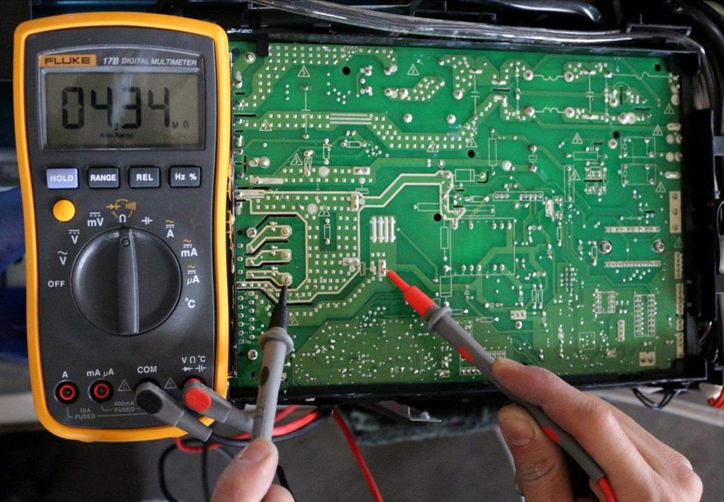
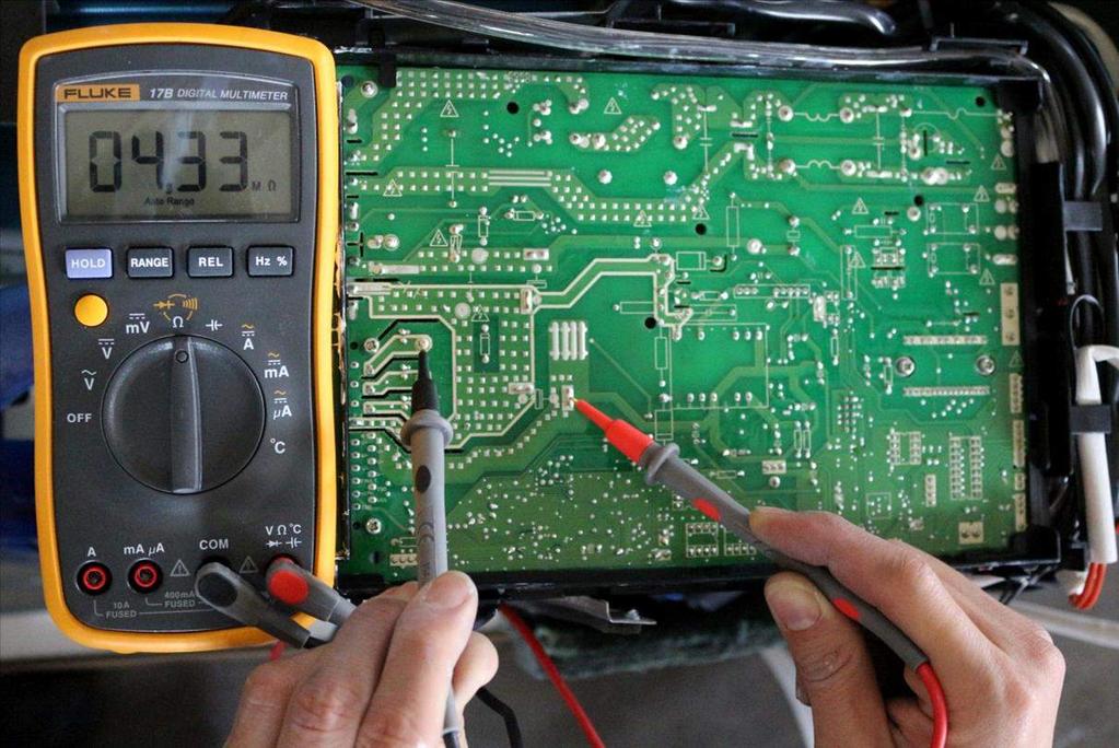
5 9.3.2 Indoor / outdoor unit s communication diagnosis and solution(e1) E1 Malfunction decision Indoor unit does not receive the feedback from outdoor unit during 110 seconds and this condition happens four times continuously. Supposed causes Wiring mistake Indoor or outdoor PCB faulty Trouble shooting: Power off, then restart the unit 2 minutes later * Measure Vs, is it positive fluctuation? (Vs is the voltage between 2 and 3 of outdoor unit. Red pan-3, Black pan-2) Check the outdoor wiring connection Check the indoor wiring connection Replace the reactor Check whether reactor is normal? Replace the indoor main PCB. Power on. Is the error extinguished? Replace the outdoor main PCB. Power on. Is the error extinguished? Replace the outdoor main PCB. Replace the indoor main PCB. * Vs is the voltage between S and N ( for 115V 2014 models) *Vs is the voltage between 2 and 3 ( for 2015 models) 29


6 Remark: Use a multimeter to test the DC voltage between 2 port and 3 port of outdoor unit. The red pin of multimeter connects with 2 port while the black pin is for 3 port. When AC is normal running, the voltage will move alternately between -50V to 50V. If the outdoor unit has malfunction, the voltage will move alternately with positive value. While if the indoor unit has malfunction, the voltage will be a certain value. Remark: Use a multimeter to test the resistance of the reactor which does not connect with capacitor. The normal value should be around zero ohm. Otherwise, the reactor must have malfunction and need to be 30
7 9.3.3 Zero crossing detection error diagnosis and solution (E2) E2 Malfunction decision When PCB does not receive zero crossing signal feedback for 4 minutes or the zero crossing signal time interval is abnormal. Supposed causes Connection mistake Trouble shooting: PCB faulty Check if the connections and power supply is normal? Correct the connections. Turn on the unit when the power supply is good. Indoor main PCB is defective. Replace indoor main PCB. 31
8 9.3.4 Fan speed has been out of control diagnosis and solution(e3) E3 Malfunction decision When indoor fan speed keeps too low (300RPM) for certain time, the unit will stop and the LED will display the failure. Supposed causes Wiring mistake Fan ass y faulty Fan motor faulty PCB faulty Trouble shooting: Power off, then restart the unit 2 minutes later The unit operates normally. Shut off the power supply, Rotate the fan by hand. Find out the cause and have it solved Check the wiring of fan motor Correct the connections. Measure the voltage for the fan motor from the main PCB Replace the main PCB Replace the fan motor 32
9 Index 1: 1:Indoor or Outdoor DC Fan Motor(control chip is in fan motor) Power on and when the unit is in standby, measure the voltage of pin1-pin3, pin4-pin3 in fan motor connector. If the value of the voltage is not in the range showing in below table, the PCB must has problems and need to be replaced. DC motor voltage input and output(voltage: V~) NO. Color Signal Voltage 1 Red Vs/Vm 280V~380V Black GND 0V 4 White Vcc V 5 Yellow Vsp 0~5.6V 6 Blue FG V DC motor voltage input and output(voltage :115V~) NO. Color Signal Voltage 1 Red Vs/Vm 140V~190V Black GND 0V 4 White Vcc V 5 Yellow Vsp 0~5.6V 6 Blue FG V 2. Outdoor DC Fan Motor (control chip is in outdoor PCB) Power on,and check if the fan can run normally, if the fan can run normally, the PCB must has problems and need to be replaced, If the fan can t run normally, measure the resistance of each two pins. If the resistance is not equal to each other, the fan motor must have problems and need to be replaced, otherwise the PCB must has problems and need to be replaced. 3. Indoor AC Fan Motor Power on and set the unit running in fan mode at high fan speed. After running for 15 seconds, measure the voltage of pin1 and pin2. If the value of the voltage is less than 100V(208~240V power supply)or 50V(115V power supply), the PCB must has problems and need to be replaced. 33

10 9.3.5 Open circuit or short circuit of temperature sensor diagnosis and solution(e5) E4/E5/F1/F2/F3 Malfunction decision If the sampling voltage is lower than 0.06V or higher than 4.94V, the LED will display the failure. Supposed causes Wiring mistake Sensor faulty Trouble shooting: PCB faulty Check the connection between temperature sensor and PCB. Correct the connection Measure the resistance value of the sensor Repalce the sensor Replace indoor or outdoor main PCB 34
11 9.3.6 Refrigerant Leakage Detection diagnosis and solution(ec) EC Malfunction decision Define the evaporator coil temp.t2 of the compressor just starts running as Tcool. In the beginning 5 minutes after the compressor starts up, if T2 <Tcool-2 C(Tcool-35.6 F) does not keep continuous 4 seconds and this situation happens 3 times, the display area will show EC and AC will turn off. Supposed causes T2 sensor faulty Trouble shooting: Power off, then restart the unit 2 minutes later. Indoor PCB faulty System problems, such as leakage or blocking. Check cool air blowing out from indoor air outlet Check if T2 sensor Check leakage of system Replace indoor PCB. check blocking of system and clear the blocking Repair the leakage and recharge the refrigerant. 35
12 9.3.6 Overload current protection diagnosis and solution(f0) F0 Malfunction decision An abnormal current rise is detected by checking the specified current detection circuit. Supposed causes Power supply problems. System blockage PCB faulty Wiring mistake Compressor malfunction Check the power supply Stop the unit Check the blockage of system Clear the blockage Check the compressor resistance values Replace the compressor Check the connections and wires Correct the connections or replace the wires. Check the reactor Replace outdoor main PCB Replace the outdoor unit 36
13 9.3.7 IPM malfunction or IGBT over-strong current protection diagnosis and solution(p0) P0 Malfunction decision When the voltage signal that IPM send to compressor drive chip is abnormal, the display LED will show P0 and AC will turn off. Supposed causes Wiring mistake IPM malfunction Outdoor fan ass y faulty Compressor malfunction Outdoor PCB faulty Trouble shooting: Check the wiring between main PCB and compressor Correct the connection or replace the wires and connectors. Check the IPM Replace the IPM board or replace the main PCB Check the outdoor fan and the outdoor unit ventilation Please refer to the solution of Fan Speed Has Been Out Of Control malfunction Check the compressor resistance values Replace the compressor. Replace the outdoor main PCB 37


14 For example: te: The photos below are only for reference, it s may be not same totally with the ones on your side. P-U P-V 38

15 P-W N-U 39

16 N-V N-W 40

17 9.3.8 Over voltage or too low voltage protection diagnosis and solution(p1) P1 Malfunction decision An abnormal voltage rise or drop is detected by checking the specified voltage detection circuit. Supposed causes Power supply problems. System leakage or block PCB faulty Trouble shooting: Check the power supply Stop the unit Check the connections and wires Correct the connections or replace the wires. Check the voltage between P and N Replace the IPM board Check the reactor Replace outdoor main PCB Replace the reactor Remark: Measure the DC voltage between P and N port. The normal value should be around 310V. P N 41
18 9.3.9 High temperature protection of compressor top diagnosis and solution(p2) P2 Malfunction decision If the sampling voltage is not 5V, the LED will display the failure. Supposed causes Power supply problems. System leakage or block PCB faulty Trouble shooting: Check the air flow system of indoor and outdoor units Clear up the air inlet and outlet or the heat exchanger of indoor and outdoor units. Power off, then restart the unit 10 minutes later Check if the temperature of compressor Check the overload protector Correct the connection. Check refrigerant system Measure the resistance between the two ports of the OLP. Is it zero? Replace the OLP. Replace the outdoor control PCB. 42
19 Inverter compressor drive error diagnosis and solution(p4) P4 Malfunction decision An abnormal inverter compressor drive is detected by a special detection circuit, including communication signal detection, voltage detection, compressor rotation speed signal detection and so on. Supposed causes Wiring mistake IPM malfunction Outdoor fan ass y faulty Compressor malfunction Outdoor PCB faulty Trouble shooting: Check the wiring between main PCB and compressor Correct the connection or replace the wires and connectors. Check the IPM Replace the IPM board or replace the main PCB Check the outdoor fan and the outdoor unit ventilation Please refer to the solution of Fan Speed Has Been Out Of Control malfunction Check the compressor resistance values Replace the compressor. Replace the outdoor main PCB 43
20 The design and specifications are subject to change without prior notice for product improvement. Consult with the sales agency or manufacturer for details.
troubleshooting Outdoor Unit: KSIE009-H221-O, KSIE012-H220-O, KSIE018-H220-O KSIE024-H220-O, KSIR036-H218, KSIR048-H218
 troubleshooting Table of Contents 1. Troubleshooting Model Numbers: Indoor Unit: KDIR09-H2, KTIR09-H2, KUIR09-H2 KDIR12-H2; KTIR12-H2, KUIR12-H2 KDIR18-H2, KTIR18-H2, KUIR18-H2 KDIR24-H2, KTIR24-H2, KUIR24-H2
KSID MINI Split DC Inverter QUICK CONNECT Air Conditioner TROUBLESHOOTING KSID016-H215Q. Model Numbers:
 KSID MINI Split DC Inverter QUICK CONNECT Air Conditioner TROUBLESHOOTING Model Numbers: KSID012-H115Q KSID022-H215Q KSID016-H215Q WARNING Installation MUST conform with local building codes or, in the
KMIR. Multi outdoor units. troubleshooting Multi zone CONDENSING UNITS MKMIR218-H221, KMIR327-H217, KMIR436-H217, KMIR545-H219.
 Multi outdoor units KMIR troubleshooting Multi zone CONDENSING UNITS Model Numbers: MKMIR218-H221, KMIR327-H217, KMIR436-H217, KMIR545-H219 Table of Contents 1. Trouble Shooting WARNING Installation MUST
LUV INVERTER SERIES. Self-diagnostics and Trouble-shooting. Part 2 of 2 42/38LUV028H 42/38LUV035H 42/38LUV052H 42/38LUV065H 42/38LUV070H 42/38LUV080H
 LUV INVERTER SERIES Part 2 of 2 Self-diagnostics and Trouble-shooting 42/38LUV028H 42/38LUV035H 42/38LUV052H 42/38LUV065H 42/38LUV070H 42/38LUV080H MAJOR COMPONENT CHECKING COMPRESSOR Use a multi-meter
LIGHT COMMERCIAL. Troublesooting
 LIGHT COMMERCIAL Troublesooting 2. 2.1 Display board 2.1.1 Icon explanation on indoor display board (Super slim cassette 24K). 2.1.2 Icon explanation on indoor display board (Compact cassette 12K, 18K).
PART7. Trouble Shooting
 PART7. Trouble Shooting 1. Indoor Unit Error Display Display E0 E1 E2 E3 E5 LED STATUS EEPROM parameter error Indoor unit and outdoor unit communication protection Zero-crossing signal error Indoor fan
SERVICE MANUAL Room Air Conditioner DC Inverter Multi Split Outdoor units
 SERVICE MANUAL Room Air Conditioner DC Inverter Multi Split Outdoor units FS2MIF-141AE2 FS2MIF-181AE2 FS3MIF-211AE2 FS3MIF-271AE2 FS4MIF-281AE2 FS4MIF-361AE2 FS5MIF-421AE0 NOTE: Before servicing the unit,
SERVICE MANUAL MIDEA AIRCONDITIONER EUROPE MARKET SUPER DC INVERTER MULTI TYPE
 SERVICE MANUAL MIDEA AIRCONDITIONER EUROPE MARKET SUPER DC INVERTER MULTI TYPE M2OE-14HFN1-Q M2OF-18HFN1-Q M3OE-21HFN1-Q M3OE-27HFN1-Q M4OE-28HFN1-Q M4OB-36HFN1-Q M5OE-42HFN1-Q DC MULTI OUTDOOR UNITS CONTENTS
GAMA DOMÉSTICA MULTISPLIT Manual de Servicio
 GAMA DOMÉSTICA MULTISPLIT Manual de Servicio CONTENTS 1. General information of Outdoor Units... 2 2. Features... 3 3. Dimensions... 4 4. Refrigeration Cycle Diagram... 5 5. Wiring diagram... 7 6. Indoor
SERVICE MANUAL MIDEA AIRCONDITIONER SUPER DC INVERTER MULTI TYPE OUTDOOR UNITS
 SERVICE MANUAL MIDEA AIRCONDITIONER SUPER DC INVERTER MULTI TYPE OUTDOOR UNITS M2OE-14HFN1-Q M2OF-18HFN1-Q M3OE-21HFN1-Q M3OE-27HFN1-Q M4OE-28HFN1-Q M4OB-36HFN1-Q M5OE-42HFN1-Q Service manual CONTENTS
SERVICE MANUAL MIDEA SUPER DC INVERTER MULTI TYPE DC MULTI OUTDOOR UNITS
 SERVICE MANUAL MIDEA SUPER DC INVERTER MULTI TYPE DC MULTI OUTDOOR UNITS M2OD-16HFN1-Q M2OD-18HFN1-Q M3OD-21HFN1-Q M3OD-26HFN1-Q M4OD-28HFN1-Q M4OA-36HFN1-Q M5OC-36HFN1-Q M5OD-42HFN1-Q CONTENTS 1. GENERAL
BRIVIS DUCTED INVERTER SERVICE MANUAL DRCi
 BRIVIS DUCTED INVERTER SERVICE MANUAL DRCi 1 TABLE OF CONTENTS TABLE OF CONTENTS... 2 IMPORTANT NOTE... 3 FAULT FINDING AND DIAGNOSTICS... 3 ABBREVIATIONS... 3 PCB S... 4 OUTDOOR MAIN PCB... 4 INDOOR PCB...
Service Manual. 9. Maintenance. 9.1 Precautions before Maintenance. discharge resistance or plug of soldering iron. Installation and Maintenance
 9. Maintenance 9.1 Precautions before Maintenance Service Manual pacitor after power off. - discharge resistance or plug of soldering iron A B A B - nance safely. 40 9.2 Error Code List O. 1 2 3 4 5 6
LG Air Conditioning Universal & Multi Split Fault Codes Sheet. Universal and Multi Split Units
 Universal and Multi Split Units If there is a fault on any LG Universal or Multi unit, a two digit number will appear on the remote controllers led display. If the unit does not have a remote controller
Fault Codes. J control
 J control Timer Temp Fault Codes 12 11 10 9 8 7 6 5 4 3 2 1 30 29 28 27 26 25 24 23 22 21 20 Enter unit inspection mode by pushing the UP and DOWN buttons simultaneously for two seconds. Ensure that the
6. Troubleshooting. 6-1 Basic items for trouble shooting. Samsung Electronics 17
 6. Troubleshooting Since the inverter air conditioner is equipped with Electrical control circuits at both Indoor & outdoor unit, the trouble shooting shall be performed according to the error mode. Inside
No Operation of air conditioner Explanation
 12. Troubleshooting 12-1 Items to be checked first 1. The input voltage should be rating voltage ±10% range. The air conditioner may not operate properly if the voltage is out of this range. 2. Is the
12. Troubleshooting Items to be checked first. Samsung Electronics
 12. Troubleshooting 12-1 Items to be checked first 1. The input voltage should be rating voltage ±10% range. The air conditioner may not operate properly if the voltage is out of this range. 2. Is the
Driftsinstruks. Utopia kontroller feilkoder PCP-2HTE og PC-ART. Vi håper de får stor glede av et Novema kulde produkt!
 Driftsinstruks Utopia kontroller feilkoder PCP-2HTE og PC-ART Vi håper de får stor glede av et vema kulde produkt! www.novemakulde.no 8/14 TROUBLESHOOTING 8.2. TROUBLESHOOTING PROCEDURE 8.2.1. ALARM CODE
9. Maintenance. 9.1 Precautions before Maintenance. Service Manual. electrolytic capacitor after power off. maintenance safely.
 9. Maintenance 9.1 Precautions before Maintenance electrolytic capacitor after power off. A B A B maintenance safely. 50 9.2 Error Code List Unit o. ame Display 8 nixie 0.5s) Operation Indicator Cool Indicator
LG Air conditioning CAC and Multi Split unit Fault code sheet Universal and Multi Split Units
 Universal and Multi Split Units If there is fault on any LG universal or multi unit a two digit number will appear on the remote controllers led display. If the unit does not have a remote controller the
SPLIT TYPE ROOM AIR CONDITIONER WALL MOUNTED TYPE
 SPLIT TYPE ROOM AIR CONDITIONER WALL MOUNTED TYPE Indoor unit ASYA24LCC ASYA24LCC ASYA24LCC Outdoor unit AOYR24LCC AOYR24LCD AOYR24LCL CONTENTS SPECIFICATIONS..................1 DIMENSIONS.....................
3. SERVICE TOOLS Inverter checker RSUK09-17 CLIMATE COMFORT. All Seasons. Heating. Air Conditioning. Applied Systems.
 All Seasons CLIMATE COMFORT Heating 3. SERVICE TOOLS 3.2. Inverter checker RSUK09-17 Air Conditioning Applied Systems Refrigeration 3.2. Inverter checker RSUK09-17: index 1. Outlook 2. How to connect?
SPLIT TYPE ROOM AIR CONDITIONER. WALL MOUNTEDtype INVERTER. Models Indoor unit Outdoor unit AOU18RLXFW AOU24RLXFW ASU18RLF ASU24RLF R410A
 SERVICE INSTRUCTION SPLIT TYPE ROOM AIR CONDITIONER WALL MOUNTEDtype INVERTER Models Indoor unit Outdoor unit ASU18RLF ASU24RLF AOU18RLXFW AOU24RLXFW R410A CONTENTS 1. DESCRIPTION OF EACH CONTROL OPERATION
WALL MOUNTED type SPLIT TYPE ROOM AIR CONDITIONER. Models
 SPLIT TYPE ROOM AIR CONDITIONER WALL MOUNTED type Models Indoor unit ASH9LSACW ASH12LSACW Outdoor unit AOH9LSAC AOH12LSAC CONTENTS SPECIFICATIONS...................... 1 DIMENSIONS..........................
4.Failure phenomenon. Mirage comes out from indoor. When the cold air from AC cools the indoor air. unit
 4.Failure phenomenon Phenomenon Mirage comes out from indoor unit Noise Sometimes, the room is smelly when heating, there is no wind at the beginning of starting unit Causing explanation When the cold
9. Maintenance. 9.1 Error Code List. Service Manual. Installation and Maintenance
 9. Maintenance 9.1 Error Code List o. ame Display Method of Outdoor Display Method of Indoor Unit Unit Indicator has 3 kinds of Indicator Display (during display status during Dual-8 ing, O 0.5s OFF ing,
HP21 SERVICE SUPPLEMENT UNIT INFORMATION. TSC6 Two-Speed Control
 SERVICE UNIT INFORMATION SUPPLEMENT HP21 Corp. 9426 L10 Litho U.S.A. All HP21-4 and -5 units (single and three phase) are equipped with a TSC6 two-speed control. The TSC6 (A14) two-speed control contains
SPLIT TYPE ROOM AIR CONDITIONER FLOOR TYPE
 SPLIT TYPE ROOM AIR CONDITIONER FLOOR TYPE Indoor unit AGYF09LAC AGYFLAC AGYFLAC AGYFLAC Outdoor unit AOYV09LAC AOYVLAC AOYVLAC AOYVLAL CONTENTS SPECIFICATIONS..................... DIMENSIONS.........................
Part 2 Functional Description
 ESIE06-0 Part Functional Description What is in this part? This part contains information on the functions used to control the system. Understanding these functions is vital when diagnosing a malfunction
ACCESSORY KIT INSTALLATION INSTRUCTIONS
 ACCESSORY KIT INSTALLATION INSTRUCTIONS Low Ambient Accessory For Air Cooled Split-System Air Conditioners YD360/480/600, YJ-30/-40/-50 and J30/40/50 YD Models 642546-UAI-A-080 GENERAL Standard operation
RAC Product Trouble Shooting Guide
 1 RAC Product Trouble Shooting Guide Model : Wall Mount Inverter Type CAUTION Make sure to fully read and understand the safety precautions described in the SVC manual before SVC. Only authorized personnel
MPPT Solar Integrated Inverters (500VA~2500VA) User Manual THE SOLAR TECH CO.,LTD. Solar Integrated Inverter Series 500VA~2500VA 13.
 User Manual THE SOLAR TECH CO.,LTD. Solar Integrated Inverter Series 500VA~2500VA 13.") MPPT Solar Integrated Inverters (500VA~2500VA) User Manual THE SOLAR TECH CO.,LTD. - 1 - Table of Contents 1. SALIENT FEATURES...3 2.. PRODUCT INSTALLATION & PRECAUTIONS...3 2.1. PRODUCT INSTALLATION &
MPPT Solar Integrated Inverters (500VA~2500VA) User Manual THE SOLAR TECH CO.,LTD. - 1 - Table of Contents 1. SALIENT FEATURES...3 2.. PRODUCT INSTALLATION & PRECAUTIONS...3 2.1. PRODUCT INSTALLATION &
MODEL UC 14YFA. Hitachi. Power Tools TECHNICAL DATA AND SERVICE MANUAL CHARGER UC 14YFA SPECIFICATIONS AND PARTS ARE SUBJECT TO CHANGE FOR IMPROVEMENT
 MODEL UC 14YFA Hitachi Power Tools CHARGER UC 14YFA TECHNICAL DATA AND SERVICE MANUAL U LIST No. F888 Aug. 2003 SPECIFICATIONS AND PARTS ARE SUBJECT TO CHANGE FOR IMPROVEMENT CONTENTS Page 1. PRODUCT NAME...1
Duplex Booster System Instruction Manual
 Duplex Booster System Instruction Manual ISO 9001 Certified Walrus America Inc Congratulations on your purchase of Walrus IC Series Inverter Control System. Please read all instructions carefully before
SERVICE MANUAL FREE COMBI SERIES FC-E24AI, FC-E28AI
 SERVICE MANUAL FREE COMBI SERIES FC-E24AI, FC-E28AI 1.Technical specifications Model Compressor Manufacturer/trademark Compressor Model Compressor Type L.R.A. (A) Compressor RLA(A) Compressor Power Input(W)
5. TROUBLE DIAGNOSIS
 . TROBLE DIAGNOSIS -1. Contents of Remote Controller Switch Alarm Display... -2-2. Outdoor nit Control anel LED Display... -4-3. AC System Alarm Codes... - -4. Inspection of arts (Outdoor nit)... -68 -.
ASU18RLB ASU24RLB AOU18RLB AOU24RLB SPLIT TYPE ROOM AIR CONDITIONER WALL MOUNTED TYPE CONTENTS
 SPLIT TYPE ROOM AIR CONDITIONER WALL MOUNTED TYPE Indoor unit ASU8RL ASURL Outdoor unit AOU8RL AOURL CONTENTS SPECIFICATIONS................... DIMENSIONS...................... REFRIGERANT SYSTEM DIAGRAM....
Users Manual. Defender 1 8.0KW to 14.0KW Online Emergency Lighting Inverter. Technical Manual # Revision B
 Users Manual Defender 1 8.0KW to 14.0KW Online Lighting Inverter Technical Manual #018-0102-01 Revision B Phone: 1.877.DSPM.POWER 1.877.377.6769 Fax: 909.930.3335 Website: www.dspmanufacturing.com E-Mail:
SBC / 2140 / Stage Battery Charger User Manual
 SBC - 2130 / 2140 / 2150 3 Stage Battery Charger User Manual Keep this manual in a safe place for quick reference at all times. This manual contains important safety and operation instructions for correct
Phoenix Inverter
 Manual EN Handleiding NL Manuel FR Anleitung DE Manual ES Appendix Phoenix Inverter 12 250 12 375 12 500 12 800 24 250 24 375 24 500 24 800 48 250 48 375 48 500 48 800 1. Safety instructions WARNING: ELECTRIC
SERVICE INSTRUCTION R410A. SPLIT TYPE ROOM AIR CONDITIONER Compact Wall Mounted Wall Mounted / Floor Compact Cassette / Slim Duct INVERTER MULTI
 SPLIT TYPE ROOM AIR CONDITIONER Compact Wall Mounted Wall Mounted / Floor Compact Cassette / Slim Duct INVERTER MULTI SERVICE INSTRUCTION Models Indoor unit Outdoor unit ASU7RLF ASU9RLF ASU2RLF ASU8RLF
Users Manual. Cobra Plus Stand-By Emergency Lighting Inverter. Technical Manual # Revision B
 Users Manual Cobra Plus Stand-By Lighting Inverter Technical Manual #018-0110-01 Revision B Phone: 1.877.DSPM.POWER 1.877.377.6769 Fax: 909.930.3335 Website: www.dspmanufacturing.com E-Mail: techsupport@dspmanufacturing.com
Outdoor UPS. User Manual. Contents. Please read carefully this manual before installing and using this product. 1 Introduction Safety...
 Contents 1 Introduction...1 2 Safety...4 3 Product Specifications...6 Outdoor UPS User Manual 4 Installation...8 4.1 Inspection...8 4.2 Installing the UPS Cabinet...8 4.3 Connecting the Power Supply...10
19,1 261,0 kw COOLING 23,7 333,0 kw HEATING
 199 RE ER RS SO AIR COOLED HEAT PUMP LIQUID CHILLERS 19,1 261,0 kw COOLING 23,7 333,0 kw HEATING R410A PLATE RCGROUP SpA 19632013 fiftycoolyears 200 VERSIONS: (R410A) Cooling capacity 19,2 261,0 kw Heating
USER S MANUAL CONTENTS. Uninterruptible Power Supply 1. INTRODUCTION SAFTY INSTRUCTION CABLE CONNECTION... 4
 USER S MANUAL ON-LINE 1K/2K/3KVA CONTENTS 1. INTRODUCTION...... 1 2. SAFTY INSTRUCTION.......... 2 3. CABLE CONNECTION.......... 4 4. SYSTEM DESCRIPTION............ 5 5. UPS OPERATION...... 12 6. TROUBLE
Technical Information and Diagnostic Guide
 Technical Information and Diagnostic Guide This guide will assist you in becoming more familiar with the working components of the NITE System and the proper steps and procedures to completely diagnose
INSTALLATION AND MAINTENANCE
 ISTALLATIO AD MAITEACE TROUBLESHOOTIG Content: 1. Precautions before Performing Inspection or Repair 2. Confirmation 3. Flashing LED of Indoor/Outdoor Unit and Primary Judgement 4. How to Check Simply
PANcharge1k Battery Charger User's Manual
 PANcharge1k Battery Charger User's Manual Ver.1.00E Table of Contents 1. Important Safety Instructions... 3 1-1 General Safety Precautions... 3 1-2 Battery Precautions... 3 1-3 Electromagnetic Disturbance...
OUTDOOR UNIT CONTROLLER (OUC)
") AUCKLAND temperzone Ltd 38 Tidal Road, Mangere, Auckland. Private Bag 93303, Otahuhu, N.Z. Phone 0-9-279 5250 Fax 0-9-275 5637 Email sales@temperzone.co.nz WELLINGTON Phone 0-4-569 3262 Fax 0-4-566 6249
AUCKLAND temperzone Ltd 38 Tidal Road, Mangere, Auckland. Private Bag 93303, Otahuhu, N.Z. Phone 0-9-279 5250 Fax 0-9-275 5637 Email sales@temperzone.co.nz WELLINGTON Phone 0-4-569 3262 Fax 0-4-566 6249
Service Manual. Extractor Model XR28QP. For The. For: Troubleshooting Adjustments
 Service Manual For The X Ride 28 Rider Extractor Model XR28QP For: Training Troubleshooting Adjustments Contents 1 Cautions ------------------------------------------------------------------------------
CEILING WALL type INVERTER
 SPLIT TYPE ROOM AIR CONDITIONER CEILING WALL type INVERTER Models Indoor unit AWY14LSAZ AWH14LSAZ AWY17LSAZ AWH17LSAZ Outdoor unit AOY14LSAWC AOH14LSAWC AOY17LSAWC AOH17LSAWC CONTENTS SPECIFICATIONS....................
 Pagina 1 di 1 INSPECTION In-car air sensor is located at crash pad. It is installed with humidity sensor. It will detect interior, which will be used for discharge control, sensor failsafe, door control,
USER MANUAL. Power GUARD UPS. Uninterruptible Power System
 USER MANUAL Power GUARD UPS Uninterruptible Power System IMPORTANT SAFETY INSTRUCTIONS SAVE THESE INSTRUCTIONS This manual contains important instructions for Power GUARD that should be followed during
Two temperature sensors to protect against freezing and high head pressure in both the indoor evaporator and the outdoor condenser
 The ZC 107 Zone Control System was designed to provide the perfect comfort control within the home. At the same time it was designed to make an airconditioning system work more efficiently and thereby
PANASONIC FAULT CODE GUIDE. ECOi ECO-G - PACi
 PANASONIC FAULT CODE GUIDE ECOi ECO-G - PACi 1 Page INDEX P3 GHP ENGINE ISSUES P4 CENTRAL CONTROLLER ISSUES P5 ADDRESSING & COMMUNICATION PROBLEMS P6 SENSOR FAULTS P7 COMPRESSOR ISSUES P8 INCORRECT SETTINGS
Electronic Ballast EVG 2000-T
 Electronic Ballast EVG 2000-T Operating Manual Table of contents 1 Description 1.1 Advantages of this ballast... 3 1.2 Functional principle... 3 1.3 Energization... 4 1.4 Visualization... 5 1.5 Indications
INSTALLATION MANUAL. Free Joint Multi & Multi-Split Type Room Air Conditioner (Cooling and Heating)
") INSTALLATION MANUAL Free Joint MH040FXEA2A MH052FXEA2A Fixed MH18VV1X MH19VV1X ENGLISH Free Joint Multi & Multi-Split Type Room Air Conditioner (Cooling and Heating) EΛΛHNIKA PORTUGUÊS ITALIANO ESPAÑOL
INSTALLATION MANUAL Free Joint MH040FXEA2A MH052FXEA2A Fixed MH18VV1X MH19VV1X ENGLISH Free Joint Multi & Multi-Split Type Room Air Conditioner (Cooling and Heating) EΛΛHNIKA PORTUGUÊS ITALIANO ESPAÑOL
SECOND GENERATION Use this guide with unit serial number prefix beginning with BWF using Terra Power separator.
 Technical Information and Diagnostic Guide for SECOND GENERATION Use this guide with unit serial number prefix beginning with BWF using Terra Power separator. This guide will assist you in becoming more
Subject Underhood G System Error Codes and Symptoms System or Parts affected
 System or Parts affected Index Underhood70G (V90Gxxx) System or Parts affected... 1 Overview... 1 Identifying your System... 1 Retrieving Logged Error Messages... 1 Error Messages... 3 Error Message Table...
1. Inspection and Maintenance
 1. and Maintenance Mandatory Be sure to inspect the inverter regularly and periodically to prevent it from breaking down because of the environment of use, such as temperature, humidity, dust and vibration,
OPEN/CLOSE SERVICE ELECTRIC ACTUATORS OPERATION AND MAINTENANCE MANUAL COMMERCIAL AND INDUSTRIAL VALVES AND AUTOMATION
 SERIES 1000-X OPEN/CLOSE SERVICE ELECTRIC ACTUATORS OPERATION AND MAINTENANCE MANUAL COMMERCIAL AND INDUSTRIAL VALVES AND AUTOMATION Publication S1000X-110 VER0215-1 For information on this product and
TECHNICAL MANUAL 2013 CONSOLE MULTI DC INVERTER
 TECHNICAL MANUAL 2013 CONSOLE MULTI DC INVERTER MODELS Indoor units BCODM26A2 BCODM36A2 BCODM53A2 Outdoor units BD2M53A3 BD3M98A3 BD4M114A3 BD5M120A3 This manual has been created for informative purpose.
13A-1 FUEL CONTENTS MULTIPOINT FUEL INJECTION (MPI) FUEL SUPPLY... 13B
 FUEL SUPPLY... 13B") 13A-1 FUEL CONTENTS MULTIPOINT FUEL INJECTION (MPI)... 13A FUEL SUPPLY... 13B 13A-2 MULTIPOINT FUEL INJECTION (MPI) CONTENTS GENERAL INFORMATION... 3 SERVICE SPECIFICATIONS... 6 SEALANT... 6 SPECIAL TOOLS...
13A-1 FUEL CONTENTS MULTIPOINT FUEL INJECTION (MPI)... 13A FUEL SUPPLY... 13B 13A-2 MULTIPOINT FUEL INJECTION (MPI) CONTENTS GENERAL INFORMATION... 3 SERVICE SPECIFICATIONS... 6 SEALANT... 6 SPECIAL TOOLS...
Technical Information and Diagnostic Guide RestStar Use this guide with 5700XE RestStar Unit. Western Star 5700XE.
 Western Star 5700XE RestStar 4 10-2017 1 Technical Information and Diagnostic Guide RestStar Use this guide with 5700XE RestStar Unit 2390 Blackhawk Road P.O. Box 6007 Rockford, IL 61125 nitesystem.com
Basic Characteristics Data
 Basic Characteristics Data Basic Characteristics Data Model ZUS1R5 ZUS ZUS6 ZUS10 ZUS15 ZUS25 ZTS1R5 ZTS ZUW1R5 ZUW ZUW6 ZUW10 ZUW15 ZUW25 ZTW1R5 ZTW Circuit method Single ended forward converter Single
AIR CONDITIONER 4 WAY CASSETTE SERIES. 1. Precautions. 2. Product Specifications. 3. Disassembly and Reassembly. 4. Troubleshooting. 5.
 SYSTEM AIR CONDITIONER 4 WAY CASSETTE SERIES Model : INDOOR UNIT AC052MN4DKH AC071MN4DKH AC090MN4DKH AC100MN4DKH AC120MN4DKH AC140MN4DKH OUTDOOR UNIT AC090MXADKH AC100MXAD H AC120MXAD H AC140MXAD H AIR
FUM-24xxCBP Series 3 Stage Battery Charger User Manual
 FUM-24xxCBP Series 3 Stage Battery Charger User Manual Keep this manual in a safe place for quick reference at all times. This manual contains important safety and operation instructions for correct use
ELECTRIC FENCE ENERGIZER SERVICE MANUAL MODEL 950 SERVICE MANUAL FOR OLLI 950 FENCE ENERGIZERS
 ELECTRIC FENCE ENERGIZER MODEL 950 SERVICE MANUAL Service Manual for OLLI 950 Page 1/16 Date 20.10.2014 Table of Contents...1 1. IMPORTANT SAFETY INSTRUCTIONS...2 2. SPECIFICATIONS...3 3. CONSTRUCTION...4
Volkswagen Golf > VW Rabbit GTI 2006-> (A5)
") Volkswagen Golf 5 2004-> VW Rabbit GTI 2006-> (A5) A/C Refrigerant System General information Note: General A/C refrigerant system servicing procedures (e.g., component/system descriptions, extracting
Volkswagen Golf 5 2004-> VW Rabbit GTI 2006-> (A5) A/C Refrigerant System General information Note: General A/C refrigerant system servicing procedures (e.g., component/system descriptions, extracting
Parts Lists. Forward Series. Rev. Feb. 2017
 s HSU09VHJ(DB)-G / HSU09VHJ(DB)-W HSU12VHJ(DB)-G / HSU12VHJ(DB)-W HSU18VHJ(DB)-G / HSU18VHJ(DB)-W HSU24VHJ(DB)-G / HSU24VHJ(DB)-W 1800 Valley Road Wayne, NJ 07470 Tel +973.617.1800 www.haier.com - Edition
ZIP Economizer Fault Detection and Diagnostics (FDD) Table
 Table") Fault Detection and Diagnostics (FDD) Table Fault Detection Problem Diagnostic ction (in addition to alarm stored / transmitted) Potential Cause C Fault Code OT sensor predetermined range O damper returns
Fault Detection and Diagnostics (FDD) Table Fault Detection Problem Diagnostic ction (in addition to alarm stored / transmitted) Potential Cause C Fault Code OT sensor predetermined range O damper returns
Ultra Sine Inverter (US) Generation 4 (G4) User Guide
 Generation 4 (G4) User Guide") IBS Intelligent Battery System GmbH Seestrasse 24, CH-3600 Thun, Schweiz Tel: +41 33 221 06 16 Fax: +41 33 221 06 17 E-Mail: info@ibs-tech.ch Ultra Sine Inverter (US) Generation 4 (G4) User Guide IBS-USG4_en_v2.0.3.doc
IBS Intelligent Battery System GmbH Seestrasse 24, CH-3600 Thun, Schweiz Tel: +41 33 221 06 16 Fax: +41 33 221 06 17 E-Mail: info@ibs-tech.ch Ultra Sine Inverter (US) Generation 4 (G4) User Guide IBS-USG4_en_v2.0.3.doc
NB NB 1511 NB NB 4031 TRUE ON-LINE DOUBLE CONVERSION UPS
 NB 0811 - NB 1511 NB 0831 - NB 4031 TRUE ON-LINE DOUBLE CONVERSION UPS LEN.MAN.UPS.069 Rev.2.00/2002 CONTENTS Safety Instructions 1 Introduction 3 2.1 FEATURE 3 2.2 UPS modules 4 How the UPS works 5 3.1
Installation Diagram of Indoor Unit and Outdoor Unit /12K 18K 24K
 /12K 18K 24K Installation Diagram of Indoor Unit and Outdoor Unit 1-1 1-1 1-1 1-1 1-2 1-2 2-1 2-1 2-2 2-3 Accessory and Option Specifications... 2-3-1 3-1 Checking before use... 3-1 3-2 Display Error and
General Precautions. Personnel Precautions
 USER MANUAL General Precautions 1. Before using Inverex, read all instructions and cautionary markings on : (1) Inverex (2) the batteries (3) this manual 2. CAUTION --To reduce risk of injury, charge only
MODEL : 55A240IUBEM ROTARY COMPRESSOR SPECIFICATION SHEET 1. APPLICATION 2. COMPRESSOR DATA 3. MOTOR DATA 4. ELECTRICAL COMPONENTS
 SPECIFICATION SHEET 1. APPLICATION H/P & Cooling Type Air conditioner Rated & Frequency... 208~230V 1Φ 60Hz Refrigerant.. R-22 2. COMPRESSOR DATA Pump Type Rolling Piston Type Displacement. 33.43cc/rev
RS485 Card. User Manual
 RS485 Card User Manual Version 1.2.2 2010.02 Page 1 Table of Contents: 1. Safety Instructions for installation and application...3 Read this User Manual before you start...5 2. Features...6 3. Appearance...7
PRODUCT CODE MODEL NAME RASC-10HNPE. No. DESCRIPTION DWG No. PART No. Qty Qty Qty Qty Qty REMARKS
 7E343107 RASC-4HNPE RASC-5HNPE RASC-6HNPE 7E343108 7E343109 No. DESCRIPTION DWG No. PART No. Qty Qty Qty Qty Qty REMARKS 1 Foot Assy XEK38712 A E04359 1 1 1 Assembly 1 Foot Assy XEK39008 A E04384 1 1 Assembly
MILWAUKEE ELECTRIC TOOL CORPORATION TEST & MEASUREMENT PRODUCT. REPAIR SERVICE INSTRUCTIONS CALIBRATION Milliamp Clamp Meter
 MILWAUKEE ELECTRIC TOOL CORPORATION TEST & MEASUREMENT PRODUCT REPAIR SERVICE INSTRUCTIONS CALIBRATION 2231-20 4-20 Milliamp Clamp Meter Environmental Condition Perform all calibration at an ambient temperature
Lithium-Ion Phosphate Battery Phantom-S Product Manual
 Lithium-Ion Phosphate Battery Phantom-S Product Manual Information Version: 1.0 This manual introduces Phantom-S from Pylontech. Please read this manual before you install the battery and follow the instruction
AIR CONDITIONER 4 WAY CASSETTE SERIES. 1. Precautions. 2. Product Specifications. 3. Disassembly and Reassembly. 4.
 SYSTEM AIR CONDITIONER 4 WAY CASSETTE SERIES INDOOR UNIT Model : AC018NN4DCH/AA AC024NN4DCH/AA AC030NN4DCH/AA AC036NN4DCH/AA AC042NN4DCH/AA AC048NN4DCH/AA OUTDOOR UNIT AC018JXADCH/AA AC024JXADCH/AA AC030JXADCH/AA
CONTENTS 1. INTRODUCTION SAFTY INSTRUCTION CABLE CONNECTION SYSTEM DESCRIPTION OPERATION... 9
 USER MANUAL 1 CONTENTS 1. INTRODUCTION... 1 2. SAFTY INSTRUCTION... 3 3. CABLE CONNECTION... 4 4. SYSTEM DESCRIPTION... 5 5. OPERATION... 9 6. TROUBLE SHOOTING GUIDE... 25 7. OPERATION MODES..... 27 8.
7 Stage Automatic Smart Battery Charger (FOR CHARGING 12V / 24V AGM, GEL,SLA AND WET BATTERIES) USER MANUAL
 USER MANUAL") 7 Stage Automatic Smart Battery Charger Desulphuration& Maintainer (FOR CHARGING 12V / 24V AGM, GEL,SLA AND WET BATTERIES) USER MANUAL THIS MANUAL CONTAINS IMPORTANT SAFETY AND OPERATING INSTRUCTIONS 1
7 Stage Automatic Smart Battery Charger Desulphuration& Maintainer (FOR CHARGING 12V / 24V AGM, GEL,SLA AND WET BATTERIES) USER MANUAL THIS MANUAL CONTAINS IMPORTANT SAFETY AND OPERATING INSTRUCTIONS 1
User Manual Rittal PMC UPS 6kVA
 User Manual Rittal PMC UPS 6kVA Germany Rittal GmbH & Co. KG Auf dem Stützelberg D-35745 Herborn Tel.: ++49-27 72-5 05-0 Fax: ++49-27 72-5 05-23 19 Internet: www.rittal.de 26 Contents 1. Introduction...
BC12M248 7 Stage Automatic Smart Battery Charger, Desulfator & Maintainer 12V, 2 / 4 / 8A FOR AGM, GEL AND WET BATTERIES USER MANUAL
 BC12M248 7 Stage Automatic Smart Battery Charger, Desulfator & Maintainer 12V, 2 / 4 / 8A FOR AGM, GEL AND WET BATTERIES USER MANUAL THIS MANUAL CONTAINS IMPORTANT SAFETY AND OPERATING INSTRUCTIONS 1 IMPORTANT
Inverter scroll compressors VZH single and manifold
 Application guidelines Inverter scroll compressors VZH088-117-170 single and manifold R410A http://cc.danfoss.com Content VZH088-117-170 - single compressors... 4 VZH088-117-170 - hybrid manifolding...
TOWA SEIDEN INDUSTRIAL CO., LTD.
 INSTRUCTION MANUAL SOUNDING LEVEL METER MODEL: TLX-120AP/200AP Meanings of indications for safety used in this Instruction Manual are as follows. WARNING: Indicates that improper handling assumes the risk
Application Engineering Europe
 Date of last update: Feb-12 Ref: D7.8.4/0112-0212/E Application Engineering Europe CORESENSE DIAGNOSTICS FOR STREAM REFRIGERATION COMPRESSORS 1/17 1 Introduction CoreSense is an ingredient brand name for
37. FATC (FULL AUTO TEMP. CONTROL) CIRCUIT 6810
 CIRCUIT 6810") 5156 6810 37. FATC (FULL AUTO TEMP. CONTROL) CIRCUIT 6810 1) CONDENSOR FAN, AIR MIX MOTOR, SUN SENSOR, WATER TEMP SENSOR A. CONNECTOR INFORMATION 6810 5157 Connector Number (Pin Number, Color) Connecting
5156 6810 37. FATC (FULL AUTO TEMP. CONTROL) CIRCUIT 6810 1) CONDENSOR FAN, AIR MIX MOTOR, SUN SENSOR, WATER TEMP SENSOR A. CONNECTOR INFORMATION 6810 5157 Connector Number (Pin Number, Color) Connecting
Application Engineering
 Application Engineering February, 2009 Copeland Digital Compressor Controller Introduction The Digital Compressor Controller is the electronics interface between the Copeland Scroll Digital Compressor
BITMAIN. APW PSU Series User Guide
 BITMAIN APW5-12- 2600 PSU Series User Guide 1 Content 1. Overview... 3 2. Features... 3 3. Specifications... 4 4. Order Information & Wire Type... 6 5. Trouble Shooting & FAQ... 7 6. Precautions for Use...
CONTENTS 1. INTRODUCTION SAFTY INSTRUCTION CABLE CONNECTION SYSTEM DESCRIPTION INVERTER OPERATION...
 CONTENTS 1. INTRODUCTION...... 1 2. SAFTY INSTRUCTION.......... 2 3. CABLE CONNECTION.......... 4 4. SYSTEM DESCRIPTION............ 5 5. INVERTER OPERATION... 11 6. TROUBLE SHOOTING GUIDE....... 16 7.
Total solder points: 126 Difficulty level: beginner advanced POWER DIMMER 230V) K8038 ILLUSTRATED ASSEMBLY MANUAL
 K8038 ILLUSTRATED ASSEMBLY MANUAL") Total solder points: 126 Difficulty level: beginner 1 2 3 4 5 advanced POWER DIMMER (1KW @ 230V) K8038 NOISE SUPPRESSED ACCORDING TO EN55015 Class microcontroller high power dimmer with non volatile memory
Total solder points: 126 Difficulty level: beginner 1 2 3 4 5 advanced POWER DIMMER (1KW @ 230V) K8038 NOISE SUPPRESSED ACCORDING TO EN55015 Class microcontroller high power dimmer with non volatile memory
OWNER S MANUAL POWER INVERTER
 OWNER S MANUAL POWER INVERTER PINV4 PINV5 PINV6 PINV4 600WATT PINV5 800WATT PINV6 1000WATT www.pyleaudio.com INTRODUCTION Thank you for purchasing the PYLE View DC to AC Power Inverter. The PINV4/PINV5/PINV6
Wiring diagrams on page 29 are for reference only. For detailed vehicle wiring refer to Navistar documents.
 1 10/2014 REV 7 !!Attention!! Before performing diagnostics: Wiring diagrams on page 29 are for reference only. For detailed vehicle wiring refer to Navistar documents. Check for Fault Codes using the
REPAIR PARTS. PTH093G Package Terminal Heat Pump
 REPAIR PARTS PTH093G Package Terminal Heat Pump PTH093G15AXXXCA PTH093G15DXXXCA PTH093G25CQXXCA PTH093G25CXXXCA PTH093G25DRXXCA PTH093G25DXXXCA PTH093G25PXXXCA PTH093G25QRXXCA PTH093G25QXXXCA PTH093G25VWXXCA
Art. No. EC-315. Art. No. EC-330. Art. No. EC-340 SWITCH-MODE BATTTERY CHARGER CONTENTS IMPORTANT SAFETY PRECAUTIONS... 2
 SWITCH-MODE BATTTERY CHARGER CONTENTS IMPORTANT SAFETY PRECAUTIONS... 2 DESCRIPTION AND FEATURES... 3 CHARGING STAGES... 4 Art. No. EC-315 Art. No. EC-330 Art. No. EC-340 PROTECTIONS... 5 INSTALLATION...
YN018GMFI16M2D-V V~ 60Hz 1Phase Serials: PRE
 Sale model: ProdCode: YN018GMFI16M2D-V1 220057000460 208-230V~ 60Hz 1Phase PRE 50130047 No. Part Name Quantity BOM code Bin Code Remark 1 Rear net 1 2011481G0001 8 2 Ambient temperature sensor assembly
Northwest RV Supply Manual Compliments of Printed From TROUBLESHOOTING
 TROUBLESHOOTING for the 5 BUTTON 3109228.001 COMFORT CONTROL CENTER SYSTEM INTRODUCTION The Comfort Control Center control system can be used to operate the following Duo-Therm Units: Roof Top Air Conditioners