Installation Diagram of Indoor Unit and Outdoor Unit /12K 18K 24K
|
|
|
- Ginger Parker
- 5 years ago
- Views:
Transcription


1 /12K 18K 24K Installation Diagram of Indoor Unit and Outdoor Unit
2 Accessory and Option Specifications Checking before use Display Error and Check Method Checking the remote controller Indoor Unit Outdoor Unit Indoor Unit Outdoor Unit Indoor Main PCB Indoor Main PCB Indoor display PBA-K Indoor display PBA-K...6-
3 Indoor Main PCB Items to be checked first Air-Purge Procedure Pump down Procedure Reference Sheet
4 1-1
5 1-2
6 2-1
7 2-2 Product Specifications 2-2,R / / 5./6 6 V. 1 / / 9% / /
8 2-2 Product Specifications / / / / / V /./ % 1. 6,R 2-3
9 2-2 Product Specifications / / / / / V / / % 1.. 6,R 2-4
10 2-2 Product Specifications / / / / / V / / % 1. 6,R 2-5
11 2-2 Product Specifications / / / / / V / / % 1 6,R 2-6

12 2-2 Product Specifications / / / / / V / / % 1,R 2-7
13 2-8
14 3-1 Checking before use 3-1
15 3-2

16

17 3-3-2 Remote controller display 3-4
18 4-1


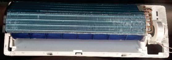
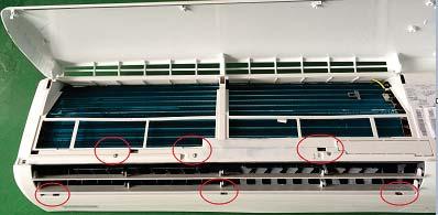
19 Open the front panel and remove it. Remove screw fixing on the terminal cover. Remove the terminal cover. Slide out the 2 air filters. 4-2


20 4-3


21 4-4


22 4-5


23 4-6


24 Open the front panel and remove it. Remove screw fixing on the terminal cover. Remove the terminal cover Slide out the 2 air filters. 4-7


25 4-8


26 4-9


27 4-10


28 4-


29 Open the front panel and remove it. Remove screw fixing on the terminal cover. Remove the terminal cover Slide out the 2 air filters. 4-12


30 4-13


31 4-14


32 4-15


33 4-16
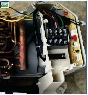
34 4-2. Outdoor Unit 4-17


35 4-2. Outdoor Unit 4-18


36 4-2. Outdoor Unit 4-19


37 4-2. Outdoor Unit 4-20


38 4-2. Outdoor Unit 4-21

39 4-2. Outdoor Unit 4-22


40 4-2. Outdoor Unit 4-23


41 4-2. Outdoor Unit 4-24


42 4-2. Outdoor Unit 4-25
43
44
45 6 6-1
46 CN1:transformer IN #1:POWER L #3:POWER N 3:POWER L (OUT) 1# POWER L (OUT) 4(AC-L):POWER L (IN) 1#POWER L (IN) CN2:transformer OUT CN3:AC-MOTOR ACN:POWER N #1:12V AC #2: 12V AC #1:Motor start capacitor #3:AC phase control singal #5:Power N #1:POWER N #2:POWER N CN8:Ion P3:Communication line CN4:MOTOR_F/B #1:AC phase control singa #3:POWER N #1:signal of communication #1:DC 5V #2:Feedback signal input #3:GND CN5:STEP MOTOR CN6:TEMPERATURE SENSOR CN4:MOTOR_F/B #1~4 STEP MOTOR signal #5: GND #1:RT_TEMP #2~3:GND #4:IPT_TEMP #1:DC 5V #2:Feedback signal input CN7:DISPLAY #1:+5V #2:GND #3:REC #4:LED1 #5:LED2 #6:LED3 #7:KEY #8:CLK #9:DATA 6-2

47 6 6-3
48 P2:POWER N #1:POWER N NO:POWER L (OUT) 1# POWER L (OUT) COM(AC-L):POWER L (IN) 1#POWER L (IN) CN11:Ion CN3:DC-MOTOR CN5-1:STEP MOTOR #1:AC phase control singa #3:POWER N #1:Feedback signal input #2 DC phase control singal #3:+15V #4 GND(hot) #5: #6 +310VDC CN5-2:STEP MOTOR #1 +12V #2~5:STEP MOTOR signal CN6:TEMPERATURE PS:Communication line CN8:DISPLAY SENSOR #1:RT_TEMP #2~3:GND #4:IPT_TEMP #1 signal of communication #1:GND #2:+5V #3:LED3 #4:LED2 #5:LED1 #6:REC #7:DATA #8:CLK 6-4

49 6 6-5
50 CN5-1:STEP MOTOR CN5-2:STEP MOTOR #1 +12V #2~5:STEP MOTOR signal NO:POWER L (OUT) 1# POWER L (OUT) COM(AC-L):POWER L (IN) 1#POWER L (IN) CN6:TEMPERATURE SENSOR CN3:DC-MOTOR P2(AC-N):POWER N #1:RT_TEMP #2~3:GND #4:IPT_TEMP #1:Feedback signal input #2 DC phase control singal #3:+15V #4 GND(hot) #5: #6 +310VDC #1:POWER N #2:POWER N FLZ:Ion P3:Communication line CN30:Programmer port #1:AC phase control singa #3:POWER N #1 signal of communication #1:GND #2:+5V #3:RESET #4:RXD #5:TXD #6:X1 #7:X2 #8:FLMD0 CN8:DISPLAY #1:GND #2:+5V #3:LED #4:SHI #5:GE #6:REC #7:SDA #8:CLK 6-6

51 6-Indoor display PBA-K CN8:DISPLAY #1:+5V #2:GND #3:REC #4:LED1 #5:LED2 #6:LED3 #7:KEY #8:CLK #9:DATA 6-7

52 6-5 Indoor display PBA-18K CN8:DISPLAY #1:GND #2:+5V #3:LED #4:SHI #5:GE #6:REC #7:SDA #8:CLK 6-8
53
54

55 8-2

56 8-3
57 Detach the assembled sensor from the PCB sensor connector and measure the sensor resistance with ohmmeter(tester) YES NO Replace the sensor Sensor resistance value : 20 C kohm 30 C kohm 35 C kohm 40 C kohm Connect the sensor to PCB connector (4pin in) supply power and measure the voltage of the connector accordingly Below 0.5V or Over 4.5V Replace the PCB 8-4
58 Is capacity of fan motor capacitor ok NO Replace it YES Is there outlet of fan connector(speed accordingly) NO Is the relay accordingly or controller silicon ok NO Replace it YES YES Check the winding of motor accordingly Replace PCB YES NO Is running of motor shaft smooth Replace it NO Replace it 8-5

59 8-6


60 8-7
61 8-8

62 8-9
63 8-10

64 Indoor display LED DISPLAY Indoor Display of LED E9 DESCRIPTION Compressor frequency drive fault Outdoor display LED DISPLAY Outdoor display of LED Outdoor unit LED Flashes (times) / / 30 LED ON Re-energize and check the protection code on display. Firstly display P0. 1 If this code is displayed when the compressor is started for several seconds or even not started, check the compressor connection for correctness, if no insert wrong, replace outdoor PCB. 2 Check if the outdoor module is tightly installed onto the radiating fins and if the silicone is applied evenly, fix the screws again if loose. 3 Check the system pressure, recharge refrigerant if the pressure is low, and discharge some refrigerant if the pressure is too high. 4 Check the outdoor ventilation and if there is any obstruction that affects the normal radiating of the air conditioner, and installation again. 5 If the above inspections are normal, but the fault remains unsolved, please replace the outdoor PCB. Re-energize and check the protection code on display. Firstly display P9. a) Check the U,V, W connection, if is correctness or loose please connect again. b) If this code is displayed when the compressor is started for several seconds or even not started, check the compressor connection for correctness, if no insert wrong, replace outdoor PCB. c) When the compressor is restarted immediately after stop, this might also cause P9 protection because the cooling system is not stable, try starting the air conditioner again after a longer period of stop. The wiring U,V,W are closed as red, white and blue respectively. Heat radiation problem easily happened while the screw is not fixed tightly. Indoor display LED DISPLAY Indoor Display of LED DESCRIPTION EU Voltage sensor fault Outdoor display LED DISPLAY Outdoor display of LED Outdoor unit LED Flashes (times) / / 13 LED ON 1 8-1
65 No 8-1
66

67
68
69
70
71
72
73
74
75
76
77 10-7 A R 1 2 J S F L B W K N/X C V INVERTER HP INVERTER CO S V KCV CV 10-8
78
LG Air conditioning CAC and Multi Split unit Fault code sheet Universal and Multi Split Units
 Universal and Multi Split Units If there is fault on any LG universal or multi unit a two digit number will appear on the remote controllers led display. If the unit does not have a remote controller the
LG Air Conditioning Universal & Multi Split Fault Codes Sheet. Universal and Multi Split Units
 Universal and Multi Split Units If there is a fault on any LG Universal or Multi unit, a two digit number will appear on the remote controllers led display. If the unit does not have a remote controller
3. SERVICE TOOLS Inverter checker RSUK09-17 CLIMATE COMFORT. All Seasons. Heating. Air Conditioning. Applied Systems.
 All Seasons CLIMATE COMFORT Heating 3. SERVICE TOOLS 3.2. Inverter checker RSUK09-17 Air Conditioning Applied Systems Refrigeration 3.2. Inverter checker RSUK09-17: index 1. Outlook 2. How to connect?
PART7. Trouble Shooting
 PART7. Trouble Shooting 1. Indoor Unit Error Display Display E0 E1 E2 E3 E5 LED STATUS EEPROM parameter error Indoor unit and outdoor unit communication protection Zero-crossing signal error Indoor fan
No Operation of air conditioner Explanation
 12. Troubleshooting 12-1 Items to be checked first 1. The input voltage should be rating voltage ±10% range. The air conditioner may not operate properly if the voltage is out of this range. 2. Is the
Service Manual. 9. Maintenance. 9.1 Precautions before Maintenance. discharge resistance or plug of soldering iron. Installation and Maintenance
 9. Maintenance 9.1 Precautions before Maintenance Service Manual pacitor after power off. - discharge resistance or plug of soldering iron A B A B - nance safely. 40 9.2 Error Code List O. 1 2 3 4 5 6
Driftsinstruks. Utopia kontroller feilkoder PCP-2HTE og PC-ART. Vi håper de får stor glede av et Novema kulde produkt!
 Driftsinstruks Utopia kontroller feilkoder PCP-2HTE og PC-ART Vi håper de får stor glede av et vema kulde produkt! www.novemakulde.no 8/14 TROUBLESHOOTING 8.2. TROUBLESHOOTING PROCEDURE 8.2.1. ALARM CODE
QUARTZ INVERTER TROUBLESHOOTING GUIDE
 QUARTZ INVERTER TROUBLESHOOTING GUIDE QIN415H2V31 QIN618H2V31 QIN721H2V31 QIN1129H2V31 INVERTER MINI SPLIT SYSTEM WARNING The information contained in the manual is intended for use by a qualified service
LUV INVERTER SERIES. Self-diagnostics and Trouble-shooting. Part 2 of 2 42/38LUV028H 42/38LUV035H 42/38LUV052H 42/38LUV065H 42/38LUV070H 42/38LUV080H
 LUV INVERTER SERIES Part 2 of 2 Self-diagnostics and Trouble-shooting 42/38LUV028H 42/38LUV035H 42/38LUV052H 42/38LUV065H 42/38LUV070H 42/38LUV080H MAJOR COMPONENT CHECKING COMPRESSOR Use a multi-meter
KSID MINI Split DC Inverter QUICK CONNECT Air Conditioner TROUBLESHOOTING KSID016-H215Q. Model Numbers:
 KSID MINI Split DC Inverter QUICK CONNECT Air Conditioner TROUBLESHOOTING Model Numbers: KSID012-H115Q KSID022-H215Q KSID016-H215Q WARNING Installation MUST conform with local building codes or, in the
12. Troubleshooting Items to be checked first. Samsung Electronics
 12. Troubleshooting 12-1 Items to be checked first 1. The input voltage should be rating voltage ±10% range. The air conditioner may not operate properly if the voltage is out of this range. 2. Is the
PANASONIC FAULT CODE GUIDE. ECOi ECO-G - PACi
 PANASONIC FAULT CODE GUIDE ECOi ECO-G - PACi 1 Page INDEX P3 GHP ENGINE ISSUES P4 CENTRAL CONTROLLER ISSUES P5 ADDRESSING & COMMUNICATION PROBLEMS P6 SENSOR FAULTS P7 COMPRESSOR ISSUES P8 INCORRECT SETTINGS
LIGHT COMMERCIAL. Troublesooting
 LIGHT COMMERCIAL Troublesooting 2. 2.1 Display board 2.1.1 Icon explanation on indoor display board (Super slim cassette 24K). 2.1.2 Icon explanation on indoor display board (Compact cassette 12K, 18K).
BRIVIS DUCTED INVERTER SERVICE MANUAL DRCi
 BRIVIS DUCTED INVERTER SERVICE MANUAL DRCi 1 TABLE OF CONTENTS TABLE OF CONTENTS... 2 IMPORTANT NOTE... 3 FAULT FINDING AND DIAGNOSTICS... 3 ABBREVIATIONS... 3 PCB S... 4 OUTDOOR MAIN PCB... 4 INDOOR PCB...
HP21 SERVICE SUPPLEMENT UNIT INFORMATION. TSC6 Two-Speed Control
 SERVICE UNIT INFORMATION SUPPLEMENT HP21 Corp. 9426 L10 Litho U.S.A. All HP21-4 and -5 units (single and three phase) are equipped with a TSC6 two-speed control. The TSC6 (A14) two-speed control contains
ACCESSORY KIT INSTALLATION INSTRUCTIONS
 ACCESSORY KIT INSTALLATION INSTRUCTIONS Low Ambient Accessory For Air Cooled Split-System Air Conditioners YD360/480/600, YJ-30/-40/-50 and J30/40/50 YD Models 642546-UAI-A-080 GENERAL Standard operation
troubleshooting Outdoor Unit: KSIE009-H221-O, KSIE012-H220-O, KSIE018-H220-O KSIE024-H220-O, KSIR036-H218, KSIR048-H218
 troubleshooting Table of Contents 1. Troubleshooting Model Numbers: Indoor Unit: KDIR09-H2, KTIR09-H2, KUIR09-H2 KDIR12-H2; KTIR12-H2, KUIR12-H2 KDIR18-H2, KTIR18-H2, KUIR18-H2 KDIR24-H2, KTIR24-H2, KUIR24-H2
Fault Codes. J control
 J control Timer Temp Fault Codes 12 11 10 9 8 7 6 5 4 3 2 1 30 29 28 27 26 25 24 23 22 21 20 Enter unit inspection mode by pushing the UP and DOWN buttons simultaneously for two seconds. Ensure that the
FOR APPROVAL SPECIFICATION OF ROTARY COMPRESSOR MODEL : UX9CJ5034ZJ7
 FOR RETURN Document No. DATE : CUSTOMER : BUYER CODE : Drafted by Checked by Reviewed by Approved by REMARKS - LIST OF ACCESSORIES FOR CUSTOMER S APPROVAL APPROVAL YES, NO DATE OF APPROVAL SIGNATURE COMPANY
ZIP Economizer Fault Detection and Diagnostics (FDD) Table
 Table") Fault Detection and Diagnostics (FDD) Table Fault Detection Problem Diagnostic ction (in addition to alarm stored / transmitted) Potential Cause C Fault Code OT sensor predetermined range O damper returns
Fault Detection and Diagnostics (FDD) Table Fault Detection Problem Diagnostic ction (in addition to alarm stored / transmitted) Potential Cause C Fault Code OT sensor predetermined range O damper returns
SPLIT TYPE ROOM AIR CONDITIONER. WALL MOUNTEDtype INVERTER. Models Indoor unit Outdoor unit AOU18RLXFW AOU24RLXFW ASU18RLF ASU24RLF R410A
 SERVICE INSTRUCTION SPLIT TYPE ROOM AIR CONDITIONER WALL MOUNTEDtype INVERTER Models Indoor unit Outdoor unit ASU18RLF ASU24RLF AOU18RLXFW AOU24RLXFW R410A CONTENTS 1. DESCRIPTION OF EACH CONTROL OPERATION
SERVICE MANUAL Room Air Conditioner DC Inverter Multi Split Outdoor units
 SERVICE MANUAL Room Air Conditioner DC Inverter Multi Split Outdoor units FS2MIF-141AE2 FS2MIF-181AE2 FS3MIF-211AE2 FS3MIF-271AE2 FS4MIF-281AE2 FS4MIF-361AE2 FS5MIF-421AE0 NOTE: Before servicing the unit,
6. Troubleshooting. 6-1 Basic items for trouble shooting. Samsung Electronics 17
 6. Troubleshooting Since the inverter air conditioner is equipped with Electrical control circuits at both Indoor & outdoor unit, the trouble shooting shall be performed according to the error mode. Inside
On Line UPS. LUC 1000E / LUC 2000E / LUC 3000E User Manual
 On Line UPS LUC 1000E / LUC 2000E / LUC 3000E User Manual Save This Manual Please read this manual carefully prior to storage, installation, wiring, operation and maintenance of the UPS. This manual contains
WALL MOUNTED type SPLIT TYPE ROOM AIR CONDITIONER. Models
 SPLIT TYPE ROOM AIR CONDITIONER WALL MOUNTED type Models Indoor unit ASH9LSACW ASH12LSACW Outdoor unit AOH9LSAC AOH12LSAC CONTENTS SPECIFICATIONS...................... 1 DIMENSIONS..........................
4.Failure phenomenon. Mirage comes out from indoor. When the cold air from AC cools the indoor air. unit
 4.Failure phenomenon Phenomenon Mirage comes out from indoor unit Noise Sometimes, the room is smelly when heating, there is no wind at the beginning of starting unit Causing explanation When the cold
SERVICE Manual AIR CONDITIONER OUTDOOR UNIT UM27B1C3 INDOOR UNIT AM27B1C07 AM27B1C Installation. 2. Disassembly and Reassembly
 ROOM AIR CONDITIONER INDOOR UNIT AM27BC07 AM27BC3 OUTDOOR UNIT UM27BC3 SERVICE Manual AIR CONDITIONER. Installation CONTENTS 2. Disassembly and Reassembly 3. Troubleshooting 4. Exploded Views and Parts
3000W HF/PFC Battery Charger
 3000W HF/PFC Battery Charger Description Advanced high frequency switching design with 92% typical efficiency Fully sealed enclosure providing improved reliability in demanding environments > 0.98 Power
9. Maintenance. 9.1 Precautions before Maintenance. Service Manual. electrolytic capacitor after power off. maintenance safely.
 9. Maintenance 9.1 Precautions before Maintenance electrolytic capacitor after power off. A B A B maintenance safely. 50 9.2 Error Code List Unit o. ame Display 8 nixie 0.5s) Operation Indicator Cool Indicator
9. Maintenance. 9.1 Error Code List. Service Manual. Installation and Maintenance
 9. Maintenance 9.1 Error Code List o. ame Display Method of Outdoor Display Method of Indoor Unit Unit Indicator has 3 kinds of Indicator Display (during display status during Dual-8 ing, O 0.5s OFF ing,
RVS-AX Instruction Manual
 RVS-AX Analog Soft Starter 8-170A, 220-600V Instruction Manual Ver. 10/11/2009 2 Table of Content RVS-AX Instruction Manual 1. TABLE OF CONTENT 1. Table of Content...2 2. Safety & Warnings...3 2.1 Safety...3
Troubleshooting Manual
 Troubleshooting Manual NOTICE: DO NOT DISCARD THIS MANUAL Models: LEGACY42-IFT PHOENIX42-IFT 1 TABLE OF CONTENTS A. Normal Operation...3 B. Wiring Diagram...4 C. Troubleshooting IntelliFire Touch...5 D.
SPLIT TYPE ROOM AIR CONDITIONER WALL MOUNTED TYPE
 SPLIT TYPE ROOM AIR CONDITIONER WALL MOUNTED TYPE Indoor unit ASYA24LCC ASYA24LCC ASYA24LCC Outdoor unit AOYR24LCC AOYR24LCD AOYR24LCL CONTENTS SPECIFICATIONS..................1 DIMENSIONS.....................
P od o u d c u t line n : S B S B Inv n erter N I P P r P esent n ation
 Product line : SB Inverter NPI Presentation Product Pure Sine Wave Inverter/Charger COMBI Available models: SB2000, 12VDC to 110/220VAC SB2000, 24VDC to 110/220VAC SB inverter dimension User benefits Feature
PFC W HF/PFC Battery Charger
 PFC 5000 5000W HF/PFC Battery Charger Description Advanced high frequency switching design with 92% typical efficiency Fully sealed enclosure providing improved reliability in demanding environments >
KMIR. Multi outdoor units. troubleshooting Multi zone CONDENSING UNITS MKMIR218-H221, KMIR327-H217, KMIR436-H217, KMIR545-H219.
 Multi outdoor units KMIR troubleshooting Multi zone CONDENSING UNITS Model Numbers: MKMIR218-H221, KMIR327-H217, KMIR436-H217, KMIR545-H219 Table of Contents 1. Trouble Shooting WARNING Installation MUST
Trouble Shooting a Jouan C/CR4.22 Centrifuge
 The world leader in serving science Trouble Shooting a Jouan C/CR4.22 Centrifuge No Spin Condition Erratic Speed Control No Cooling General Parts List Wiring Diagram No Spin Condition (Removing the Front
CX-SERIES ADVANCED BATTERY CHARGER
 CX-SERIES ADVANCED BATTERY CHARGER Table of Content 1. IMPORTANT SAFETY INFORMATION... 2 1-1 General Safety Precautions... 2 1-2 Battery Precautions... 2 2. FEATURES... 3 2-1 Battery Charging Curve...
ADVANCED PID TROUBLESHOOTING
 ADVANCED PID TROUBLESHOOTING August 29, 2016 A KEY POINT If the drive is telling you something via a Fault, then the problem is probably not the drive. The drive is recognizing a fault and telling you
c-go 12V/10A 12V/20A Power supply and battery charger Instruction manual
 c-go 12V/10A 12V/20A Power supply and battery charger GB Instruction manual 1 Index 1. Product description... 2 2. Safety advices... 3 3. Mounting and installation... 4 4. Operation... 5 5. Problem solving...
SAFETY WARNINGS AND GUIDELINES
 SAFETY WARNINGS AND GUIDELINES Place the inverter in a well-ventilated environment. Ensure that the cooling fan is not blocked and that it operates as intended. Do not use the inverter if the fan fails
SERVICE MANUAL MIDEA AIRCONDITIONER EUROPE MARKET SUPER DC INVERTER MULTI TYPE
 SERVICE MANUAL MIDEA AIRCONDITIONER EUROPE MARKET SUPER DC INVERTER MULTI TYPE M2OE-14HFN1-Q M2OF-18HFN1-Q M3OE-21HFN1-Q M3OE-27HFN1-Q M4OE-28HFN1-Q M4OB-36HFN1-Q M5OE-42HFN1-Q DC MULTI OUTDOOR UNITS CONTENTS
OUTDOOR UNIT CONTROLLER (OUC)
") AUCKLAND temperzone Ltd 38 Tidal Road, Mangere, Auckland. Private Bag 93303, Otahuhu, N.Z. Phone 0-9-279 5250 Fax 0-9-275 5637 Email sales@temperzone.co.nz WELLINGTON Phone 0-4-569 3262 Fax 0-4-566 6249
AUCKLAND temperzone Ltd 38 Tidal Road, Mangere, Auckland. Private Bag 93303, Otahuhu, N.Z. Phone 0-9-279 5250 Fax 0-9-275 5637 Email sales@temperzone.co.nz WELLINGTON Phone 0-4-569 3262 Fax 0-4-566 6249
OFF GRID SOLAR INVERTER
 OFF GRID SOLAR INVERTER Summarize series inverter is one of the most advanced DC to AC conversion products in the world, it has the main advantages of high quality sine wave AC output, microcomputer control,
Motor. Document # Vari-Green Motor and Controls. Table of Contents. Features, Operation, Wiring and Troubleshooting
 Document #473681 Vari-Green Motor and Controls Installation, Operation and Maintenance Manual Please read and save these instructions for future reference. Read carefully before attempting to assemble,
YN012GMFI16RUD Decription: Model Number: Product Code: Power Supply:
 YN012GMFI16RUD 220037506240 1 Ambient temperature sensor assembly 1 202301310063 4 2 Rear net 1 201237490045 5 3 Condenser assembly 1 201537490008 617 4 Pipe temperature sensor assembly 1 202440500004
Advanced EasyStart Troubleshooting
 Advanced EasyStart Troubleshooting EasyStart is designed for excellent reliability and durability. Every EasyStart is tested on a compressor before it leaves Micro-Air to ensure it will work when delivered.
Kelly HSR Series Motor Controller with Regen User s Manual V 3.3. Kelly HSR Opto-Isolated Series Motor Controller with Regen.
 Kelly HSR Opto-Isolated Series Motor Controller with Regen User s Manual HSR72601 HSR72801 HSR12401 HSR12601 HSR12901 HSR14301 HSR14501 HSR14701 Rev.3.3 Dec. 2011 Contents Chapter 1 Introduction... 2 1.1
Energy-saving Servo Motor
 Energy-saving Servo Motor User Guide Perface GAUTION: PLEASE READ INSTEUCTION MANUAL CAREFULLY BEFORE OPERATEING. THE INSTALLATION AND OPERATION MUST BE OPERATE UNDER PROFESSIONAL TRAINED STAFF. This product
Part 2 Functional Description
 ESIE06-0 Part Functional Description What is in this part? This part contains information on the functions used to control the system. Understanding these functions is vital when diagnosing a malfunction
Application Engineering
 Application Engineering February, 2009 Copeland Digital Compressor Controller Introduction The Digital Compressor Controller is the electronics interface between the Copeland Scroll Digital Compressor
DC TO AC PURE SINE POWER INVERTER PWRI18012S INSTRUCTION MANUAL
 DC TO AC PURE SINE POWER INVERTER PWRI18012S INSTRUCTION MANUAL 1 A. INTRODUCTION The AIMS Power pure sine inverter product line is used for back-up power. The pure sine product line is ideal for sensitive
V 2.0 DC TO AC POWER INVERTER PWRINV500012W PWRINV500024W PWRINV500036W PWRINV500048W. Instruction Manual
 DC TO AC POWER INVERTER PWRINV500012W PWRINV500024W PWRINV500036W PWRINV500048W Instruction Manual Introduction The AIMS Power 5000 Watt series inverters are the most advanced line of mobile DC to AC power
FES 14S Discharging assistant
 FES 14S Discharging assistant Suitable for FES GEN1 (14S) battery pack, and FES GEN2 (14S) battery pack User manual, Version 1.2 LZ design d.o.o., Brod 3D, 1370 Logatec, Slovenia tel +386 59 948 898 info@lzdesign.si
ZONE CONTROLLER Air Conditioners
 INSTALLATION MANUAL LS KEEP THIS MANUAL IN A HANDY PLACE FOR FUTURE REFERENCE. 2 CONTENTS SAFETY CONSIDERATIONS........................................................ 4 ACCESSORIES...................................................................
Wiring diagrams on page 29 are for reference only. For detailed vehicle wiring refer to Navistar documents.
 1 10/2014 REV 7 !!Attention!! Before performing diagnostics: Wiring diagrams on page 29 are for reference only. For detailed vehicle wiring refer to Navistar documents. Check for Fault Codes using the
Multi Air Conditioner SVC MANUAL(Exploded View)
") Internal Use nly http://biz.lgservice.com Multi Air Conditioner SVC MANUAL(Exploded View) MDEL : A2UW18GFA0 [LMU18CHV] CAUTIN Before Servicing the unit, read the safety precautions in General SVC manual.
Internal Use nly http://biz.lgservice.com Multi Air Conditioner SVC MANUAL(Exploded View) MDEL : A2UW18GFA0 [LMU18CHV] CAUTIN Before Servicing the unit, read the safety precautions in General SVC manual.
EcoNet and Flash Codes
 The error codes below will be displayed at the EcoNet Control Center under Service window / Current Faults or in the Fault History and will be time & date stamped. VSODC (Variable Speed Outdoor Unit Control
DC Microgrids and Distribution Systems for Residences
 Microgrids and Distribution Systems for Residences Toshifumi ISE, Hiroaki KAKIGANO (Osaka University, JAPAN) Outline of the Presentation 1. Introduction 2. System Configuration and Control Scheme 3. System
GAMA DOMÉSTICA MULTISPLIT Manual de Servicio
 GAMA DOMÉSTICA MULTISPLIT Manual de Servicio CONTENTS 1. General information of Outdoor Units... 2 2. Features... 3 3. Dimensions... 4 4. Refrigeration Cycle Diagram... 5 5. Wiring diagram... 7 6. Indoor
SPLIT TYPE ROOM AIR CONDITIONER FLOOR TYPE
 SPLIT TYPE ROOM AIR CONDITIONER FLOOR TYPE Indoor unit AGYF09LAC AGYFLAC AGYFLAC AGYFLAC Outdoor unit AOYV09LAC AOYVLAC AOYVLAC AOYVLAL CONTENTS SPECIFICATIONS..................... DIMENSIONS.........................
Technical Support Division GD CHIGO HEATING & VENTILATION EQUIPMENT CO., LTD.
 Technical Support Division 2013.12 1 1. External appearance 2. Nomenclature 3. Specifications 4. Dimensions 5. Service space 6. Piping diagram 7. Wiring diagram 8. Capacity tables 9. Electric characteristics
Application Engineering
 Application Engineering March 2011 Copeland Digital Compressor Controller Introduction The Digital Compressor Controller is the electronics interface between the Copeland Scroll Digital compressor or the
MODEL 2001 HERMETI-CHECK OPERATING INSTRUCTIONS
 MODEL 2001 HERMETI-CHECK OPERATING INSTRUCTIONS Model 2001 HERMETI-CHECK tests all single phase compressors up to 5 HP, 110, 220, or 277 volts. The HERMETI-CHECK comes equipped with a built in 200 micro
Power Supply EL
 General information: EL610-2412-24 with dual outputs has been specifically developed to meet the DC powering requirements for telecommunications, industrial and marine applications. The unit has a 230Vac,
Inverter PAC. Introduction. March 2009
 Inverter PAC Introduction March 2009 Inverter driven PAC Contents 1. Line up 2. Model name 3. Concept and the technical feature 1. Compactness of the outdoor unit 2. weight-saving outdoor unit 3. Improved
AIR CONDITIONER 4 WAY CASSETTE SERIES. 1. Precautions. 2. Product Specifications. 3. Disassembly and Reassembly. 4.
 SYSTEM AIR CONDITIONER 4 WAY CASSETTE SERIES INDOOR UNIT Model : AC018NN4DCH/AA AC024NN4DCH/AA AC030NN4DCH/AA AC036NN4DCH/AA AC042NN4DCH/AA AC048NN4DCH/AA OUTDOOR UNIT AC018JXADCH/AA AC024JXADCH/AA AC030JXADCH/AA
DC TO AC POWER INVERTER PWRIC150012W INSTRUCTION MANUAL
 DC TO AC POWER INVERTER PWRIC150012W INSTRUCTION MANUAL SAVE THIS MANUAL You will need the manual for the safety warnings and precautions, assembly instructions, operating and maintenance procedures, parts
CX Series User s Manual
 CX Series User s Manual Advanced Converter / Charger Legal Provisions Copyrights 2016 COTEK Electronic IND. CO. All Rights Reserved. Any part of this document may not be reproduced in any form for any
AIR CONDITIONER 4 WAY CASSETTE SERIES. 1. Precautions. 2. Product Specifications. 3. Disassembly and Reassembly. 4. Troubleshooting. 5.
 SYSTEM AIR CONDITIONER 4 WAY CASSETTE SERIES Model : INDOOR UNIT AC052MN4DKH AC071MN4DKH AC090MN4DKH AC100MN4DKH AC120MN4DKH AC140MN4DKH OUTDOOR UNIT AC090MXADKH AC100MXAD H AC120MXAD H AC140MXAD H AIR
SERVICE MANUAL OUTDOOR UNIT. No. OB386
 SPLIT-TYPE AIR CONDITIONERS Revision D: MU-A20VB- E and MU-A5VB- E have been added. Please void OB86 REVISED EDITION-C. OUTDOOR UNIT SERVICE MANUAL HFC utilized R40A No. OB86 REVISED EDITION-D Models MU-A20VB-
Fault Code Check List
 Fault Code Check List This Fault Code Check List is intended to provide an easy-to-use, quick reference guide on all Fault Codes across our product range. As the information in here is limited, please
YN018GMFI16M2D-V V~ 60Hz 1Phase Serials: PRE
 Sale model: ProdCode: YN018GMFI16M2D-V1 220057000460 208-230V~ 60Hz 1Phase PRE 50130047 No. Part Name Quantity BOM code Bin Code Remark 1 Rear net 1 2011481G0001 8 2 Ambient temperature sensor assembly
SERVICE MANUAL MIDEA AIRCONDITIONER SUPER DC INVERTER MULTI TYPE OUTDOOR UNITS
 SERVICE MANUAL MIDEA AIRCONDITIONER SUPER DC INVERTER MULTI TYPE OUTDOOR UNITS M2OE-14HFN1-Q M2OF-18HFN1-Q M3OE-21HFN1-Q M3OE-27HFN1-Q M4OE-28HFN1-Q M4OB-36HFN1-Q M5OE-42HFN1-Q Service manual CONTENTS
WARNING. Trouble Shooting Bunk Lift Control Box For In-wall Slim Rack Systems. Content. Table of Contents:
 Trouble Shooting Bunk Lift Control Box 1510000199 For In-wall Slim Rack Systems Content Copyright Power Gear Issued: January 2013 #82-S0530, Rev. OA Read, understand and follow all instructions in Installation
Technical Support Division GD CHIGO HEATING & VENTILATION EQUIPMENT CO., LTD.
 Technical Support Division 2012.10 1 1. External appearance 2. Nomenclature 3. Specifications 4. Dimensions 5. Service space 6. Piping diagram 7. Wiring diagram 8. Capacity tables 9. Electric characteristics
8 Troubleshooting and Maintenance
 8 Troubleshooting and Maintenance 8.1 Troubleshooting 8.1.1 Troubleshooting of LED Indicators See Tab. 7-4 State Descriptions of LED Indicators for the definition. Fault Type LED indicators and LCD screen
Special Specification 6058 Battery Back-Up System for Signal Cabinets
 Special Specification Battery Back-Up System for Signal Cabinets 1. DESCRIPTION 2. DEFINITIONS Install a Battery Back-Up System (BBU System) for traffic signals that will provide reliable emergency power
Induction Power Supplies
 Induction Power Supplies 7.5kW; 135 400kHz 480V version (Integral Heat Station) User s Guide Model 7.5-135/400-3-480 SMD Control Brds Rev. D 5/08 Table of Contents 1. Specifications and features...3 2.
PROTECTGLOBAL.COM TROUBLE SHOOTER
 PROTECTGLOBAL.COM TROUBLE SHOOTER ERROR EXPLANATION POSSIBLE SOLUTION E 1 Main supply 230 V off Check power supply and fuses, transformer connections. E 2 E 3 E 4 E 5 E 6 E 7 E 8 Low fluidmessage Fire
RHINO MOTION CONTROLS
 Installation Manual and Datasheet http://www.rhinomotioncontrols.com Page 1 [] Key Features Smooth and quiet operation at all speeds and extremely low motor heating Industrial grade performance for 2-Phase
c-go 24V/6A 24V/8A 24V/12A
 c-go 24V/6A 24V/8A 24V/12A Battery charger GB Instruction manual 1 Index 1. Product description... 2 2. Safety advices... 3 3. Quick start guide... 4 4. Operation... 4 5. Problem solving... 6 6. Specifications...
Outdoor UPS. User Manual. Contents. Please read carefully this manual before installing and using this product. 1 Introduction Safety...
 Contents 1 Introduction...1 2 Safety...4 3 Product Specifications...6 Outdoor UPS User Manual 4 Installation...8 4.1 Inspection...8 4.2 Installing the UPS Cabinet...8 4.3 Connecting the Power Supply...10
SERVICE & OWNER S MANUAL
 1 of 10 SERVICE & OWNER S MANUAL Product Specifications 25 x 36 x 7 Weight: 47 lbs. Air Flow: 260 CFM Air Conditioner p/n: 1ACUNIT-G1 Fits with Curtis Roof Kit: Contact Curtis for Details. Fits with Curtis
SERVICE INSTRUCTION R410A. SPLIT TYPE ROOM AIR CONDITIONER Compact Wall Mounted Wall Mounted / Floor Compact Cassette / Slim Duct INVERTER MULTI
 SPLIT TYPE ROOM AIR CONDITIONER Compact Wall Mounted Wall Mounted / Floor Compact Cassette / Slim Duct INVERTER MULTI SERVICE INSTRUCTION Models Indoor unit Outdoor unit ASU7RLF ASU9RLF ASU2RLF ASU8RLF
General Precautions. Personnel Precautions
 USER MANUAL General Precautions 1. Before using Inverex, read all instructions and cautionary markings on : (1) Inverex (2) the batteries (3) this manual 2. CAUTION --To reduce risk of injury, charge only
 Pagina 1 di 1 INSPECTION In-car air sensor is located at crash pad. It is installed with humidity sensor. It will detect interior, which will be used for discharge control, sensor failsafe, door control,
SLIDING DOOR OPERATOR INSTRUCTION MANUAL
 SLIDING DOOR OPERATOR INSTRUCTION MANUAL (MODEL NO. 1071.101 & 1071.102) Please carefully keep this manual for good maintenance. Caution Be sure the door opener is far away from moisture, vibration, and
Parts Lists. Forward Series. Rev. Feb. 2017
 s HSU09VHJ(DB)-G / HSU09VHJ(DB)-W HSU12VHJ(DB)-G / HSU12VHJ(DB)-W HSU18VHJ(DB)-G / HSU18VHJ(DB)-W HSU24VHJ(DB)-G / HSU24VHJ(DB)-W 1800 Valley Road Wayne, NJ 07470 Tel +973.617.1800 www.haier.com - Edition
5. TROUBLE DIAGNOSIS
 . TROBLE DIAGNOSIS -1. Contents of Remote Controller Switch Alarm Display... -2-2. Outdoor nit Control anel LED Display... -4-3. AC System Alarm Codes... - -4. Inspection of arts (Outdoor nit)... -68 -.
Installation, Operation and Maintenance Manual
 Document 473681 Vari-Green Motor and Controls Installation, Operation and Maintenance Manual Please read and save these instructions for future reference. Read carefully before attempting to assemble,
A/C PRESSURE MONITOR INSTALLATION INSTRUCTIONS SYSTEM OPERATION GREEN INDICATOR LIGHT
 A/C PRESSURE MONITOR INSTALLATION INSTRUCTIONS Do not attempt to clean or inspect anything while the engine is running. Cleaning and inspection must be done by a certified mechanic. All A/C service must
Pure Sine Wave Power Inverter SSW A SSW A SSW A SSW A SSW A
 Pure Sine Wave Power Inverter SSW-350-12A SSW-600-12A SSW-1000-12A SSW-1500-12A SSW-2000-12A Owner's Manual Please read this manual before installing your inverter 1 IMPORTANT SAFETY INSTRUCTIONS THIS
APS & APS
 POWER INVERTER APS1000-12 & APS2000-24 Table of Contents Important Safety Information...................... 1 General Safety Precautions...................... 1 Precautions When Working With Batteries..............
MRXBOX-VSC Visual System User Control Installation and Maintenance
 MRXBOX-VSC Visual System User Control Installation and Maintenance The EMC Directive 2014/30/EU The Low Voltage Directive 2014/35/EU 1.0 INTRODUCTION The MRXBOX-VSC is a user control from the Ecosmart
HEAVY DUTY POWER RELAYS FEATURES
 VDE VC HEAVY DUTY POWER RELAYS VC RELAYS Faston terminal Screw terminal mm 9 FEATURES VC power relays are designed for controlling heavy duty loads safely: Contact gap of 3 mm or more -point contacts for
WALL MOUNTED type SPLIT TYPE ROOM AIR CONDITIONER ASY9USBCW AOY9UGBC ASY12USBCW AOY12UGBC. Models Indoor unit Outdoor unit
 SPLIT TYPE ROOM AIR CONDITIONER WALL MOUNTED type Models Indoor unit Outdoor unit ASY9USBCW AOY9UGBC ASY12USBCW AOY12UGBC CONTENTS SPECIFICATIONS....................... 1 OUTLINE AND DIMENSIONS............
SERVICE MANUAL MU-A09YV - E1 MU-A09YV - MU-A12YV - E1 HFC. Wireless type Models SPLIT-TYPE, AIR CONDITIONERS. No. OB330 R410A CONTENTS.
 SPLIT-TYPE, AIR CONDITIONERS Revision A: MU-A2YV - E can be connected to MCF-A2WV - E. Please void OB330. SERVICE MANUAL Wireless type Models E MU-A07YV - E MU-A09YV - MU-A2YV - E HFC utilized R40A No.
TECHNICAL MANUAL 2013 CONSOLE MULTI DC INVERTER
 TECHNICAL MANUAL 2013 CONSOLE MULTI DC INVERTER MODELS Indoor units BCODM26A2 BCODM36A2 BCODM53A2 Outdoor units BD2M53A3 BD3M98A3 BD4M114A3 BD5M120A3 This manual has been created for informative purpose.
User Manual. 3/1 10K/20K Online UPS with Isolation Transformer. Uninterruptible Power Supply System
 User Manual 3/1 10K/20K Online UPS with Isolation Transformer Uninterruptible Power Supply System Please comply with all warnings and operating instructions in this manual strictly. Save this manual properly