troubleshooting Outdoor Unit: KSIE009-H221-O, KSIE012-H220-O, KSIE018-H220-O KSIE024-H220-O, KSIR036-H218, KSIR048-H218
|
|
|
- Nathaniel Mills
- 5 years ago
- Views:
Transcription


1 troubleshooting Table of Contents 1. Troubleshooting Model Numbers: Indoor Unit: KDIR09-H2, KTIR09-H2, KUIR09-H2 KDIR12-H2; KTIR12-H2, KUIR12-H2 KDIR18-H2, KTIR18-H2, KUIR18-H2 KDIR24-H2, KTIR24-H2, KUIR24-H2 KDIR036-H2G1, KTIR036-H2G1, KFUF036-H2G1 KDIR048-H2G1, KTIR048-H2G1, KFUF048-H2G1 Outdoor Unit: KSIE009-H221-O, KSIE012-H220-O, KSIE018-H220-O KSIE024-H220-O, KSIR036-H218, KSIR048-H218 WARNING Installation MUST conform with local building codes or, in the absence of local codes, with the National Electrical Code NFPA70/ANSI C or current edition and Canadian Electrical Code Part1 CSA C The information contained in the manual is intended for use by a qualified service technician familiar with safety procedures and equipped with the proper tools and test instruments Installation or repairs made by unqualified persons can result in hazards to you and others. Failure to carefully read and follow all instructions in this manual can result in equipment malfunction, property damage, personal injury and/or death. This service is only for service engineer to use.
2 16. Troubleshooting Safety Electricity is stored in capacitors, even when the power supply is shut off. Do not forget to discharge the electricity in the capacitors. Electrolytic Capacitors (HIGH VOLTAGE! CAUTION!) For other models, For other models, connect a discharge resistor (approx.100ω 40W) or a soldering iron plug between the + and - terminals of the electrolytic capacitor on the opposite side of the outdoor printed circuit board (PCB). te: The picture above is for reference purposes only. The design of the devices depicted may vary by model. 1
3 16.1 Indoor Unit Error Display Operation lamp Timer lamp Display LED STATUS 1 time X E0 Indoor unit EEPROM parameter error 2 times X E1 Communication malfunction between indoor and outdoor units 4 times X E3 Indoor fan speed malfunction 5 times X E4 Indoor room temperature sensor (T1 ) malfunction 6 times X E5 Evaporator coil temperature sensor (T2) malfunction 7 times X EC Refrigerant leakage detection 8 times X EE Water-level alarm malfunction 1 time O F0 Current overload protection 2 times O F1 Outdoor ambient temperature sensor (T4 ) malfunction 3 times O F2 Condenser coil temperature sensor (T3) malfunction 4 times O F3 Compressor discharge temperature sensor (T5) malfunction 5 times O F4 Outdoor unit EEPROM parameter error 6 times O F5 Outdoor fan speed malfunction 7 times O F6 8 times O F7 Indoor coil outlet pipe sensor(located on outdoor unit low pressure valve) Communication malfunction between Cassette optional lift panel and the unit 9 times O F8 Cassette optional lift panel malfunction 10 times O F9 Cassette optional lift panel not closed 1 times P0 Inverter module (IPM) malfunction 2 times P1 Over-voltage or under-voltage protection 3 times P2 Compressor top high temperature protection (OLP) 4 times P3 Low ambient temperature cut off in heating 5 times P4 Compressor drive malfunction 6 times P5 Indoor units mode conflict 7 times P6 Low pressure protection 8 times P7 Outdoor IPM temperature sensor error O(light) X(off) (flash) 2
4 16.2 Outdoor unit error display For 9K-24K outdoor unit:. Problems LED2 (Green) LED1 (Red) IU display 1 standby for normal O X 2 Operation normally X O 3 Compressor drive board EEPROM error O E5 4 IPM malfunction or IGBT over-strong current protection X P0 5 Over voltage or too low voltage protection O O P1 6 Inverter compressor drive error X P4 7 Inverter compressor drive error O P4 8 Communication malfunction between main control board and driver board P4 3
5 For 36K-48K Outdoor Unit Problems Error Code 1 Communication malfunction between indoor and outdoor units E1 2 Current overload protection F0 3 Outdoor ambient temperature sensor (T4 ) malfunction F1 4 Condenser coil temperature sensor (T3) malfunction F2 5 Compressor discharge temperature sensor (T5) malfunction F3 6 Outdoor unit EEPROM parameter error F4 7 Outdoor fan speed malfunction F5 8 Inverter module (IPM) malfunction P0 9 Over-voltage or under-voltage protection P1 10 Compressor top high temperature protection (OLP) P2 11 Low ambient temperature cut off in heating P3 12 Compressor drive malfunction P4 13 High temperature protection of indoor coil in heating J0 14 Outdoor temperature protection of outdoor coil in cooling J1 15 Temperature protection of compressor discharge J2 16 PFC module protection J3 17 Communication malfunction between control board and IPM board J4 18 High pressure protection J5 19 Low pressure protection J6 20 Outdoor IPM module temperature sensor malfunction P7 21 AC voltage protection J8 Outdoor check function N Display Remark 00 rmal display Display running frequency, running state or malfunction code 01 Indoor unit capacity demand code Actual data*hp*10 If capacity demand code is higher than 99, the digital display tube will show single digit and tens digit. (For example, the digital display tube show 5.0,it means the capacity demand is 15. the digital display tube show 60,it means the capacity demand is 6.0) 02 Amendatory capacity demand code 03 The frequency after the capacity requirement transfer 04 The frequency after the frequency limit 05 The frequency of sending to 341 chip 06 If the temp. is lower than 0 degree, the digital display tube Indoor unit evaporator outlet temp.(heating T2, will show 0.If the temp. is higher than 70 degree, the digital cooling T2B) display tube will show Condenser pipe temp.(t3) If the temp. is lower than -9 degree, the digital display tube 4
6 08 Outdoor ambient temp.(t4) will show -9.If the temp. is higher than 70 degree, the digital display tube will show 70. If the indoor unit is not connected, the digital display tube will show: 09 Compressor discharge temp.(t5) The display value is between 13~129 degree. If the temp. is lower than 13 degree, the digital display tube will show 13.If the temp. is higher than 99 degree, the digital display tube will show single digit and tens digit. (For example, the digital display tube show 0.5,it means the compressor discharge temp. is 105 degree. the digital display tube show 1.6,it means the compressor discharge temp. is 116 degree) 10 AD value of current 11 AD value of voltage The display value is hex number. 12 Indoor unit running mode code Off:0, Fan only 1,Cooling:2, Heating:3 13 Outdoor unit running mode code Off:0, Fan only 1,Cooling:2, Heating:3, Forced cooling:4 14 EXV open angle Actual data/4. If the value is higher than 99, the digital display tube will show single digit and tens digit. For example, the digital display tube show 2.0,it means the EXV open angle is 120 4=480p.) Bit7 Frequency limit caused by IGBT radiator Bit6 The display value is Frequency limit caused by hex number. For PFC 15 Frequency limit symbol example, the digital Bit5 Frequency limit caused by T4. display tube show Bit4 Frequency limit caused by T2. 2A, then Bit5=1, Bit3 Frequency limit caused by T3. Bit3=1, Bit1=1. Bit2 Frequency limit caused by T5. It means frequency Bit1 Frequency limit caused by limit caused by T4, current T3 and current. Bit0 voltage Frequency limit caused by 16 DC fan motor speed 17 IGBT radiator temp. The display value is between 30~120 degree. If the temp. is lower than 30 degree, the digital display tube will show 30.If the temp. is higher than 99 degree, the digital display tube will show single digit and tens digit. (For example, the digital display tube show 0.5,it means the IGBT radiator temp. is 105 degree. the digital display tube show 1.6,it means the IGBT radiator temp. is 116 degree) 18 Indoor unit number The indoor unit can communicate with outdoor unit well. General:1, Twins:2 19 Evaporator pipe temp. T2 of 1# indoor unit If the temp. is lower than 0 degree, the digital display tube 20 Evaporator pipe temp. T2 of 2# indoor unit will show 0.If the temp. is higher than 70 degree, the digital display tube will show 70. If the indoor unit is not 21 Evaporator pipe temp. T2 of 3# indoor unit 5
7 connected, the digital display tube will show: 22 1# Indoor unit capacity demand code 23 2# Indoor unit capacity demand code 24 3# Indoor unit capacity demand code Actual data*hp*10 If capacity demand code is higher than 99, the digital display tube will show single digit and tens digit. (For example, the digital display tube show 5.0,it means the capacity demand is 15. the digital display tube show 60,it means the capacity demand is 6.0). If the indoor unit is not connected, the digital display tube will show: 25 Room temp. T1 of 1# indoor unit If the temp. is lower than 0 degree, the digital display tube 26 Room temp. T1 of 2# indoor unit will show 0.If the temp. is higher than 70 degree, the digital display tube will show 70. If the indoor unit is not 27 Average room temp. T1 connected, the digital display tube will show: 28 Reason of stop 29 Evaporator pipe temp. T2B of 1# indoor unit 30 Evaporator pipe temp. T2B of 2# indoor unit If the temp. is lower than 0 degree, the digital display tube will show 0.If the temp. is higher than 70 degree, the digital display tube will show 70. If the indoor unit is not connected, the digital display tube will show: 6


8 16.3 Diagnosis and Solution EEPROM parameter error diagnosis and solution (E0/F4) Error Code E0/F4 Malfunction conditions Indoor or outdoor PCB main chip does not receive feedback from EEPROM chip. Potential causes Installation mistake Trouble shooting: Power off, then restart the unit 2 minutes later. Does a problem still remain? Faulty PCB Replace the indoor/outdoor main PCB. EEPROM: a type of read-only memory. The contents can be erased and reprogrammed using a pulsed voltage. To locate the EEPROM chip, Indoor PCB Outdoor PCB te: The two photos above are only for reference purposes only. The design of the devices depicted may vary by model. 7
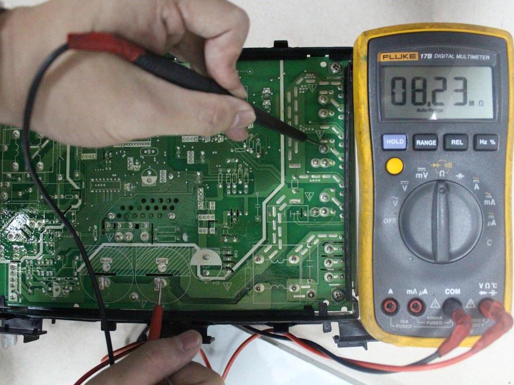
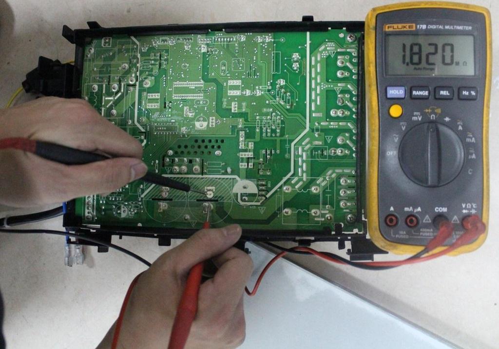
9 Communication malfunction between indoor and outdoor units diagnosis and solution (E1) For 9K-24K: Error Code E1 Malfunction conditions If the indoor unit does not receive feedback from outdoor unit for 110 seconds 4 consecutive times. Potential causes Wiring mistake Faulty indoor or outdoor PCB Trouble shooting: Power off, then restart the unit 2 minutes later Measure Vs, is it positive fluctuation? (Vs is the voltage between 3 and 2 of outdoor unit. Red pan-3, Black pan-2) Check the outdoor wiring connection Check the indoor wiring connection Replace the reactor Check whether reactor is normal? Replace the indoor main PCB. Power on. Is the error extinguished? Replace the outdoor main PCB. Power on. Is the error extinguished? Replace the outdoor main PCB. Replace the indoor main PCB. 8


10 Remark: Use a multimeter to test the DC voltage between 2 port and 3 port of outdoor unit. The red pin of multimeter connects with 2 port while the black pin is for 3 port. When AC is normal running, the voltage will move alternately between -50V to 50V. If the outdoor unit has malfunction, the voltage will move alternately with positive value. While if the indoor unit has malfunction, the voltage will be a certain value. Remark, The old label is L1,L2,S, L1,L2 The new label is 1, 2, 3, L1,L2 Remark: Use a multimeter to test the resistance of the reactor which does not connect with capacitor. The normal value should be around zero ohm. Otherwise, the reactor must have malfunction and need to be replaced. 9
11 For 36K-48K: Malfunction conditions Possible causes Indoor unit does not receive feedback from outdoor unit for 60 seconds OR outdoor unit does not receive feedback from indoor unit for 120 seconds. Wiring mistakes Faulty indoor or outdoor PCB E1 displayed Communication malfunction between indoor and outdoor units Power off, then restart the unit 2 minutes later. Does a problem still exist? Is there any interference such as too many lamps, power transformers? Or is the signal wire too long? Remove interference or add magnet ring on power wire Is the signal wire a shield cable and is the shield cable a earthing? Adopt shield cable/shield cable earthing Is the signal wire is broken? Replace the signal wire Are the signal wires properly inserted on PCB? Pull out and insert back Replace the indoor main PCB, is the error resolved? Replace the outdoor Main PCB. 10
12 Fan speed malfunction diagnosis and solution (E3) Error Code E3 Malfunction conditions When indoor fan speed is too low (300RPM) for a certain period of time, the unit ceases operation and the LED displays a failure code. Potential Causes Wiring mistake Faulty fan assembly Faulty fan motor Faulty PCB Trouble shooting: Power off, then restart the unit after 2 minutes. Does a problem remain? The unit is operating normally Shut off the power supply, Rotate the fan by hand. Does it turn easily? Find the cause of the problem and resolve it Check the wiring of fan motor. Is it improperly wired? Correct the connections. Measure the voltage for the fan motor from the main PCB. Is it within normal parameters? Replace the main PCB Replace the fan motor 11
13 Index 1: 1. Indoor DC fan motor (Control Chip is in Fan Motor) Turn power on and while the unit is on standby, measure the voltage between pin1 and pin3 as well as between pin4 and pin3 in fan motor connector. If the value of the voltage is not within the range shown in the following table, the PCB may be experiencing problems and need to be replaced. DC motor voltage input and output NO. Color Signal Voltage 1 Red Vs/Vm 200~380V Black GND 0V 4 White Vcc 13.5~16.5V 5 Yellow Vsp 0~6.5V 6 Blue FG 13.5~16.5V 12

14 Open or short circuit of temperature sensor diagnosis and solution (E4/E5/F1/F2/F3) Error Code E4/E5/F1/F2/F3 Malfunction conditions If the sampling voltage is lower than 0.06V or higher than 4.94V, the LED displays a failure. Potential causes Wiring mistake Faulty sensor Trouble shooting: Faulty PCB Check the connection between temperature sensor and PCB. Is it properly wired? Ensure proper connection Measure the resistance value of the sensor. Is it within acceptable parameters? Replace the sensor Replace indoor or outdoor main PCB 13
15 Refrigerant Leakage Detection diagnosis and solution (EC) Error Code EC Malfunction conditions Define the evaporator coil temperature T2 of the compressor starts running as Tcool. If the following occurs 3 times, the display shows "EC" and the unit switches off: In the first 8 minutes after the compressor starts up, if T2 < Tcool-2 is not maintained for 4 seconds and compressor running frequency is not higher than 50Hz for 3 minutes Potential Causes Faulty T2 sensor Trouble shooting: Faulty indoor PCB System problems, such as leakage or blockages Power off, then restart the unit 2 minutes later. Does a problem still remain? Is there cool air blowing out from indoor air outlet? Check the T2 sensor. Is it securely attached? Check system for leakages. Are any leakages present? Replace the indoor PCB Check System for blockages and clear blockages if present Repair the leakage and recharge the refrigerant 14
16 Water-level alarm malfunction diagnosis and solution Error Code EE Malfunction conditions If the sampling voltage is not 5V, the LED will display the failure code. Possible causes Wiring mistakes Faulty water-level switch Faulty water pump Faulty indoor PCB Power off, then restart the unit 3 minutes later. Is it still displaying the error code? If the water-level switch is inserted well? Insert the water-level switch well If the water-level switch is broken? Replace the water-level switch Replace the water pump, If malfunction is still not solved Replace the indoor main PCB 15
17 IPM malfunction or IGBT over-strong current protection diagnosis and solution (P0) Error Code Malfunction conditions P0 Possible causes off. Wiring mistake Trouble shooting: When the voltage signal the IPM sends to the compressor drive chip is abnormal, the display LED shows P0 and the AC turn IPM malfunction Faulty outdoor fan assembly Check the wiring between main PCB and compressor. Does an error exist? Ensure a proper connection or replace the wires and connectors Check the IPM. Is it in working order? Replace the IPM board or replace the main PCB Check the outdoor fan and the outdoor unit ventilation. Is it in working order? Please refer to the solution to the fan speed is out of control malfunction Check the compressor resistance values. Are they within acceptable parameters? Replace the compressor Replace the outdoor main PCB 16

18 P-U P-V 17

19 P-W P-N 18

20 Over voltage or too low voltage protection diagnosis and solution (P1) Error Code P1 Malfunction conditions Abnormal increases or decreases in voltage are detected by checking the specified voltage detection circuit. Potential causes Power supply issues System leakage or blockage Faulty PCB Trouble shooting: Check the power supply. Is it in working order? Turn off the unit Check the connections and w i r e s. Are they in working order? Turn power on and while the unit is on standby, check if the voltage between P and N is at DC 310V, 340V or 380V? Then start up the unit and measure the voltage between P and N. Is it in now between 220V~400V? Check the reactor. Is it in working order? Ensure proper connections or replace the wires Replace the IPM board Replace outdoor main PCB Replace the reactor Remark: Measure the DC voltage between P and N port. The normal value should be around 310V.340V or 380V 19
21 High temperature protection of compressor top diagnosis and solution (P2) Error Code Malfunction decision conditions Supposed causes Trouble shooting: P2 If the sampling voltage is not 5V, the LED will display the failure. Power supply problems. System leakage or block PCB faulty Check the air flow system of indoor and outdoor units. Does a problem exist? Clear up the air inlet and outlet or the heat exchanger of the indoor and outdoor units. Power off and then restart the unit 10 minutes afterwards Check compressor temperature. Is it within acceptable parameters? Check the overload protector. Is it properly wired? Ensure a proper connection Check the refrigerant system. Is it functioning properly? Measure the resistance between the two ports of the OLP. Is it zero? Replace the OLP Replace the outdoor control PCB 20
22 Inverter compressor drive error diagnosis and solution(p4) Error Code P4 Malfunction conditions Abnormalities in the inverter compressor drive is detected by a special detection circuit, which can perform communication signal detection, voltage detection, and compressor rotation speed signal detection. Potential causes Wiring mistake IPM malfunction Faulty outdoor fan assembly Compressor malfunction Faulty outdoor PCB Trouble shooting: Check the wiring between the main PCB and compressor. Is it improperly wired? Ensure proper connection or replace the wires and connectors Check the IPM. Is it functioning properly? Replace the IPM board or replace the main PCB Check the outdoor fan and the outdoor unit ventilation. Is it functioning properly? Please refer to Fan Speed Malfunction Check the compressor resistance values. Are they within acceptable parameters? Replace the compressor Replace the outdoor main PCB 21
23 16.4 Main parts check 1. Temperature sensor checking Disconnect the temperature sensor from PCB, measure the resistance value with a tester. Temperature Sensors. Room temp.(t1) sensor, Indoor coil temp.(t2) sensor, Outdoor coil temp.(t3) sensor, Outdoor ambient temp.(t4) sensor, Compressor discharge temp.(t5) sensor. Measure the resistance value of each winding by using the multi-meter. 22
24 The Klimaire logo is a registered Trademark of Klimaire Products inc. Copyright 2016 Klimaire Products Inc NW 89 Place, Doral, FL USA Tel: (305) Fax (305) sales@klimaire.com The design and specifications are subject to change without prior notice for product improvement. Consult with the sales agency or manufacturer for details.
QUARTZ INVERTER TROUBLESHOOTING GUIDE
 QUARTZ INVERTER TROUBLESHOOTING GUIDE QIN415H2V31 QIN618H2V31 QIN721H2V31 QIN1129H2V31 INVERTER MINI SPLIT SYSTEM WARNING The information contained in the manual is intended for use by a qualified service
KSID MINI Split DC Inverter QUICK CONNECT Air Conditioner TROUBLESHOOTING KSID016-H215Q. Model Numbers:
 KSID MINI Split DC Inverter QUICK CONNECT Air Conditioner TROUBLESHOOTING Model Numbers: KSID012-H115Q KSID022-H215Q KSID016-H215Q WARNING Installation MUST conform with local building codes or, in the
KMIR. Multi outdoor units. troubleshooting Multi zone CONDENSING UNITS MKMIR218-H221, KMIR327-H217, KMIR436-H217, KMIR545-H219.
 Multi outdoor units KMIR troubleshooting Multi zone CONDENSING UNITS Model Numbers: MKMIR218-H221, KMIR327-H217, KMIR436-H217, KMIR545-H219 Table of Contents 1. Trouble Shooting WARNING Installation MUST
LIGHT COMMERCIAL. Troublesooting
 LIGHT COMMERCIAL Troublesooting 2. 2.1 Display board 2.1.1 Icon explanation on indoor display board (Super slim cassette 24K). 2.1.2 Icon explanation on indoor display board (Compact cassette 12K, 18K).
LUV INVERTER SERIES. Self-diagnostics and Trouble-shooting. Part 2 of 2 42/38LUV028H 42/38LUV035H 42/38LUV052H 42/38LUV065H 42/38LUV070H 42/38LUV080H
 LUV INVERTER SERIES Part 2 of 2 Self-diagnostics and Trouble-shooting 42/38LUV028H 42/38LUV035H 42/38LUV052H 42/38LUV065H 42/38LUV070H 42/38LUV080H MAJOR COMPONENT CHECKING COMPRESSOR Use a multi-meter
SERVICE MANUAL Room Air Conditioner DC Inverter Multi Split Outdoor units
 SERVICE MANUAL Room Air Conditioner DC Inverter Multi Split Outdoor units FS2MIF-141AE2 FS2MIF-181AE2 FS3MIF-211AE2 FS3MIF-271AE2 FS4MIF-281AE2 FS4MIF-361AE2 FS5MIF-421AE0 NOTE: Before servicing the unit,
PART7. Trouble Shooting
 PART7. Trouble Shooting 1. Indoor Unit Error Display Display E0 E1 E2 E3 E5 LED STATUS EEPROM parameter error Indoor unit and outdoor unit communication protection Zero-crossing signal error Indoor fan
SERVICE MANUAL MIDEA AIRCONDITIONER EUROPE MARKET SUPER DC INVERTER MULTI TYPE
 SERVICE MANUAL MIDEA AIRCONDITIONER EUROPE MARKET SUPER DC INVERTER MULTI TYPE M2OE-14HFN1-Q M2OF-18HFN1-Q M3OE-21HFN1-Q M3OE-27HFN1-Q M4OE-28HFN1-Q M4OB-36HFN1-Q M5OE-42HFN1-Q DC MULTI OUTDOOR UNITS CONTENTS
GAMA DOMÉSTICA MULTISPLIT Manual de Servicio
 GAMA DOMÉSTICA MULTISPLIT Manual de Servicio CONTENTS 1. General information of Outdoor Units... 2 2. Features... 3 3. Dimensions... 4 4. Refrigeration Cycle Diagram... 5 5. Wiring diagram... 7 6. Indoor
BRIVIS DUCTED INVERTER SERVICE MANUAL DRCi
 BRIVIS DUCTED INVERTER SERVICE MANUAL DRCi 1 TABLE OF CONTENTS TABLE OF CONTENTS... 2 IMPORTANT NOTE... 3 FAULT FINDING AND DIAGNOSTICS... 3 ABBREVIATIONS... 3 PCB S... 4 OUTDOOR MAIN PCB... 4 INDOOR PCB...
SERVICE MANUAL MIDEA AIRCONDITIONER SUPER DC INVERTER MULTI TYPE OUTDOOR UNITS
 SERVICE MANUAL MIDEA AIRCONDITIONER SUPER DC INVERTER MULTI TYPE OUTDOOR UNITS M2OE-14HFN1-Q M2OF-18HFN1-Q M3OE-21HFN1-Q M3OE-27HFN1-Q M4OE-28HFN1-Q M4OB-36HFN1-Q M5OE-42HFN1-Q Service manual CONTENTS
SERVICE MANUAL MIDEA SUPER DC INVERTER MULTI TYPE DC MULTI OUTDOOR UNITS
 SERVICE MANUAL MIDEA SUPER DC INVERTER MULTI TYPE DC MULTI OUTDOOR UNITS M2OD-16HFN1-Q M2OD-18HFN1-Q M3OD-21HFN1-Q M3OD-26HFN1-Q M4OD-28HFN1-Q M4OA-36HFN1-Q M5OC-36HFN1-Q M5OD-42HFN1-Q CONTENTS 1. GENERAL
LG Air Conditioning Universal & Multi Split Fault Codes Sheet. Universal and Multi Split Units
 Universal and Multi Split Units If there is a fault on any LG Universal or Multi unit, a two digit number will appear on the remote controllers led display. If the unit does not have a remote controller
Service Manual. 9. Maintenance. 9.1 Precautions before Maintenance. discharge resistance or plug of soldering iron. Installation and Maintenance
 9. Maintenance 9.1 Precautions before Maintenance Service Manual pacitor after power off. - discharge resistance or plug of soldering iron A B A B - nance safely. 40 9.2 Error Code List O. 1 2 3 4 5 6
6. Troubleshooting. 6-1 Basic items for trouble shooting. Samsung Electronics 17
 6. Troubleshooting Since the inverter air conditioner is equipped with Electrical control circuits at both Indoor & outdoor unit, the trouble shooting shall be performed according to the error mode. Inside
Driftsinstruks. Utopia kontroller feilkoder PCP-2HTE og PC-ART. Vi håper de får stor glede av et Novema kulde produkt!
 Driftsinstruks Utopia kontroller feilkoder PCP-2HTE og PC-ART Vi håper de får stor glede av et vema kulde produkt! www.novemakulde.no 8/14 TROUBLESHOOTING 8.2. TROUBLESHOOTING PROCEDURE 8.2.1. ALARM CODE
9. Maintenance. 9.1 Precautions before Maintenance. Service Manual. electrolytic capacitor after power off. maintenance safely.
 9. Maintenance 9.1 Precautions before Maintenance electrolytic capacitor after power off. A B A B maintenance safely. 50 9.2 Error Code List Unit o. ame Display 8 nixie 0.5s) Operation Indicator Cool Indicator
No Operation of air conditioner Explanation
 12. Troubleshooting 12-1 Items to be checked first 1. The input voltage should be rating voltage ±10% range. The air conditioner may not operate properly if the voltage is out of this range. 2. Is the
LG Air conditioning CAC and Multi Split unit Fault code sheet Universal and Multi Split Units
 Universal and Multi Split Units If there is fault on any LG universal or multi unit a two digit number will appear on the remote controllers led display. If the unit does not have a remote controller the
12. Troubleshooting Items to be checked first. Samsung Electronics
 12. Troubleshooting 12-1 Items to be checked first 1. The input voltage should be rating voltage ±10% range. The air conditioner may not operate properly if the voltage is out of this range. 2. Is the
Fault Codes. J control
 J control Timer Temp Fault Codes 12 11 10 9 8 7 6 5 4 3 2 1 30 29 28 27 26 25 24 23 22 21 20 Enter unit inspection mode by pushing the UP and DOWN buttons simultaneously for two seconds. Ensure that the
9. Maintenance. 9.1 Error Code List. Service Manual. Installation and Maintenance
 9. Maintenance 9.1 Error Code List o. ame Display Method of Outdoor Display Method of Indoor Unit Unit Indicator has 3 kinds of Indicator Display (during display status during Dual-8 ing, O 0.5s OFF ing,
SPLIT TYPE ROOM AIR CONDITIONER WALL MOUNTED TYPE
 SPLIT TYPE ROOM AIR CONDITIONER WALL MOUNTED TYPE Indoor unit ASYA24LCC ASYA24LCC ASYA24LCC Outdoor unit AOYR24LCC AOYR24LCD AOYR24LCL CONTENTS SPECIFICATIONS..................1 DIMENSIONS.....................
4.Failure phenomenon. Mirage comes out from indoor. When the cold air from AC cools the indoor air. unit
 4.Failure phenomenon Phenomenon Mirage comes out from indoor unit Noise Sometimes, the room is smelly when heating, there is no wind at the beginning of starting unit Causing explanation When the cold
5. TROUBLE DIAGNOSIS
 . TROBLE DIAGNOSIS -1. Contents of Remote Controller Switch Alarm Display... -2-2. Outdoor nit Control anel LED Display... -4-3. AC System Alarm Codes... - -4. Inspection of arts (Outdoor nit)... -68 -.
HP21 SERVICE SUPPLEMENT UNIT INFORMATION. TSC6 Two-Speed Control
 SERVICE UNIT INFORMATION SUPPLEMENT HP21 Corp. 9426 L10 Litho U.S.A. All HP21-4 and -5 units (single and three phase) are equipped with a TSC6 two-speed control. The TSC6 (A14) two-speed control contains
Application Engineering
 Application Engineering February, 2009 Copeland Digital Compressor Controller Introduction The Digital Compressor Controller is the electronics interface between the Copeland Scroll Digital Compressor
ACCESSORY KIT INSTALLATION INSTRUCTIONS
 ACCESSORY KIT INSTALLATION INSTRUCTIONS Low Ambient Accessory For Air Cooled Split-System Air Conditioners YD360/480/600, YJ-30/-40/-50 and J30/40/50 YD Models 642546-UAI-A-080 GENERAL Standard operation
Application Engineering
 Application Engineering March 2011 Copeland Digital Compressor Controller Introduction The Digital Compressor Controller is the electronics interface between the Copeland Scroll Digital compressor or the
Parts Lists. Forward Series. Rev. Feb. 2017
 s HSU09VHJ(DB)-G / HSU09VHJ(DB)-W HSU12VHJ(DB)-G / HSU12VHJ(DB)-W HSU18VHJ(DB)-G / HSU18VHJ(DB)-W HSU24VHJ(DB)-G / HSU24VHJ(DB)-W 1800 Valley Road Wayne, NJ 07470 Tel +973.617.1800 www.haier.com - Edition
SPLIT TYPE ROOM AIR CONDITIONER. WALL MOUNTEDtype INVERTER. Models Indoor unit Outdoor unit AOU18RLXFW AOU24RLXFW ASU18RLF ASU24RLF R410A
 SERVICE INSTRUCTION SPLIT TYPE ROOM AIR CONDITIONER WALL MOUNTEDtype INVERTER Models Indoor unit Outdoor unit ASU18RLF ASU24RLF AOU18RLXFW AOU24RLXFW R410A CONTENTS 1. DESCRIPTION OF EACH CONTROL OPERATION
ASU18RLB ASU24RLB AOU18RLB AOU24RLB SPLIT TYPE ROOM AIR CONDITIONER WALL MOUNTED TYPE CONTENTS
 SPLIT TYPE ROOM AIR CONDITIONER WALL MOUNTED TYPE Indoor unit ASU8RL ASURL Outdoor unit AOU8RL AOURL CONTENTS SPECIFICATIONS................... DIMENSIONS...................... REFRIGERANT SYSTEM DIAGRAM....
3. SERVICE TOOLS Inverter checker RSUK09-17 CLIMATE COMFORT. All Seasons. Heating. Air Conditioning. Applied Systems.
 All Seasons CLIMATE COMFORT Heating 3. SERVICE TOOLS 3.2. Inverter checker RSUK09-17 Air Conditioning Applied Systems Refrigeration 3.2. Inverter checker RSUK09-17: index 1. Outlook 2. How to connect?
SERVICE MANUAL FREE COMBI SERIES FC-E24AI, FC-E28AI
 SERVICE MANUAL FREE COMBI SERIES FC-E24AI, FC-E28AI 1.Technical specifications Model Compressor Manufacturer/trademark Compressor Model Compressor Type L.R.A. (A) Compressor RLA(A) Compressor Power Input(W)
Technical Support Division GD CHIGO HEATING & VENTILATION EQUIPMENT CO., LTD.
 Technical Support Division 2012.10 1 1. External appearance 2. Nomenclature 3. Specifications 4. Dimensions 5. Service space 6. Piping diagram 7. Wiring diagram 8. Capacity tables 9. Electric characteristics
MPPT Solar Integrated Inverters (500VA~2500VA) User Manual THE SOLAR TECH CO.,LTD. Solar Integrated Inverter Series 500VA~2500VA 13.
 User Manual THE SOLAR TECH CO.,LTD. Solar Integrated Inverter Series 500VA~2500VA 13.") MPPT Solar Integrated Inverters (500VA~2500VA) User Manual THE SOLAR TECH CO.,LTD. - 1 - Table of Contents 1. SALIENT FEATURES...3 2.. PRODUCT INSTALLATION & PRECAUTIONS...3 2.1. PRODUCT INSTALLATION &
MPPT Solar Integrated Inverters (500VA~2500VA) User Manual THE SOLAR TECH CO.,LTD. - 1 - Table of Contents 1. SALIENT FEATURES...3 2.. PRODUCT INSTALLATION & PRECAUTIONS...3 2.1. PRODUCT INSTALLATION &
WALL MOUNTED type SPLIT TYPE ROOM AIR CONDITIONER. Models
 SPLIT TYPE ROOM AIR CONDITIONER WALL MOUNTED type Models Indoor unit ASH9LSACW ASH12LSACW Outdoor unit AOH9LSAC AOH12LSAC CONTENTS SPECIFICATIONS...................... 1 DIMENSIONS..........................
Application Engineering Europe
 Date of last update: Feb-12 Ref: D7.8.4/0112-0212/E Application Engineering Europe CORESENSE DIAGNOSTICS FOR STREAM REFRIGERATION COMPRESSORS 1/17 1 Introduction CoreSense is an ingredient brand name for
Parts Lists. Novel Series. Rev. Feb. 2017
 s HSU09VHG(DB)-G / HSU09VHG(DB)-W HSU12VHG(DB)-G / HSU12VHG(DB)-W HSU18VHG(DB)-G / HSU18VHG(DB)-W HSU24VHG(DB)-G / HSU24VHG(DB)-W 1800 Valley Road Wayne, NJ 07470 Tel +973.617.1800 www.haier.com - Edition
INSTALLATION MANUAL. Free Joint Multi & Multi-Split Type Room Air Conditioner (Cooling and Heating)
") INSTALLATION MANUAL Free Joint MH040FXEA2A MH052FXEA2A Fixed MH18VV1X MH19VV1X ENGLISH Free Joint Multi & Multi-Split Type Room Air Conditioner (Cooling and Heating) EΛΛHNIKA PORTUGUÊS ITALIANO ESPAÑOL
INSTALLATION MANUAL Free Joint MH040FXEA2A MH052FXEA2A Fixed MH18VV1X MH19VV1X ENGLISH Free Joint Multi & Multi-Split Type Room Air Conditioner (Cooling and Heating) EΛΛHNIKA PORTUGUÊS ITALIANO ESPAÑOL
YN018GMFI16M2D-V V~ 60Hz 1Phase Serials: PRE
 Sale model: ProdCode: YN018GMFI16M2D-V1 220057000460 208-230V~ 60Hz 1Phase PRE 50130047 No. Part Name Quantity BOM code Bin Code Remark 1 Rear net 1 2011481G0001 8 2 Ambient temperature sensor assembly
Technical Support Division GD CHIGO HEATING & VENTILATION EQUIPMENT CO., LTD.
 Technical Support Division 2013.12 1 1. External appearance 2. Nomenclature 3. Specifications 4. Dimensions 5. Service space 6. Piping diagram 7. Wiring diagram 8. Capacity tables 9. Electric characteristics
YSmart Technology Co., Ltd. User Manual. GTI Grid Series. GTI Series Inverters for Grid-connected PV system
 YSmart Technology Co., Ltd. User Manual Contact Us Address: No. 30 XinFeng Road,Potoubei Village,Ailian Town,Longgang Dist, Shenzhen 51872,P.R. China Tel: (86)755-85232255 Fax: (86)755-85232255 Email :
AIR CONDITIONER 4 WAY CASSETTE SERIES. 1. Precautions. 2. Product Specifications. 3. Disassembly and Reassembly. 4.
 SYSTEM AIR CONDITIONER 4 WAY CASSETTE SERIES INDOOR UNIT Model : AC018NN4DCH/AA AC024NN4DCH/AA AC030NN4DCH/AA AC036NN4DCH/AA AC042NN4DCH/AA AC048NN4DCH/AA OUTDOOR UNIT AC018JXADCH/AA AC024JXADCH/AA AC030JXADCH/AA
YN012GMFI16RUD Decription: Model Number: Product Code: Power Supply:
 YN012GMFI16RUD 220037506240 1 Ambient temperature sensor assembly 1 202301310063 4 2 Rear net 1 201237490045 5 3 Condenser assembly 1 201537490008 617 4 Pipe temperature sensor assembly 1 202440500004
SPLIT TYPE ROOM AIR CONDITIONER FLOOR TYPE
 SPLIT TYPE ROOM AIR CONDITIONER FLOOR TYPE Indoor unit AGYF09LAC AGYFLAC AGYFLAC AGYFLAC Outdoor unit AOYV09LAC AOYVLAC AOYVLAC AOYVLAL CONTENTS SPECIFICATIONS..................... DIMENSIONS.........................
Phoenix Inverter
 Manual EN Handleiding NL Manuel FR Anleitung DE Manual ES Appendix Phoenix Inverter 12 250 12 375 12 500 12 800 24 250 24 375 24 500 24 800 48 250 48 375 48 500 48 800 1. Safety instructions WARNING: ELECTRIC
CORESENSE DIAGNOSTICS FOR STREAM REFRIGERATION COMPRESSORS
 Date of last update: Apr-15 Ref: D7.8.4/0112-0415/E Application Engineering Europe CORESENSE DIAGNOSTICS FOR STREAM REFRIGERATION COMPRESSORS CoreSense Diagnostics for Stream Refrigeration Compressors...
INSTALLATION AND MAINTENANCE
 ISTALLATIO AD MAITEACE TROUBLESHOOTIG Content: 1. Precautions before Performing Inspection or Repair 2. Confirmation 3. Flashing LED of Indoor/Outdoor Unit and Primary Judgement 4. How to Check Simply
RAC Product Trouble Shooting Guide
 1 RAC Product Trouble Shooting Guide Model : Wall Mount Inverter Type CAUTION Make sure to fully read and understand the safety precautions described in the SVC manual before SVC. Only authorized personnel
ZIP Economizer Fault Detection and Diagnostics (FDD) Table
 Table") Fault Detection and Diagnostics (FDD) Table Fault Detection Problem Diagnostic ction (in addition to alarm stored / transmitted) Potential Cause C Fault Code OT sensor predetermined range O damper returns
Fault Detection and Diagnostics (FDD) Table Fault Detection Problem Diagnostic ction (in addition to alarm stored / transmitted) Potential Cause C Fault Code OT sensor predetermined range O damper returns
Users Manual. Defender 1 8.0KW to 14.0KW Online Emergency Lighting Inverter. Technical Manual # Revision B
 Users Manual Defender 1 8.0KW to 14.0KW Online Lighting Inverter Technical Manual #018-0102-01 Revision B Phone: 1.877.DSPM.POWER 1.877.377.6769 Fax: 909.930.3335 Website: www.dspmanufacturing.com E-Mail:
High Frequency SineWave Guardian TM
 High Frequency SineWave Guardian TM 380V 480V INSTALLATION GUIDE FORM: SHF-IG-E REL. January 2018 REV. 002 2018 MTE Corporation High Voltage! Only a qualified electrician can carry out the electrical installation
USER MANUAL MPS 1-5KW SERIES
 USER MANUAL MPS 1-5KW SERIES Low Series Frequency Solar and Wind Power Charging Inverter CONTENTS 1 WWW.NEXTGENNRG.COM 1. Introduction... 3 2. Profile Structure 4 2.1. Working Principle 4 2.2.Product Features..5
PRODUCT CODE MODEL NAME RASC-10HNPE. No. DESCRIPTION DWG No. PART No. Qty Qty Qty Qty Qty REMARKS
 7E343107 RASC-4HNPE RASC-5HNPE RASC-6HNPE 7E343108 7E343109 No. DESCRIPTION DWG No. PART No. Qty Qty Qty Qty Qty REMARKS 1 Foot Assy XEK38712 A E04359 1 1 1 Assembly 1 Foot Assy XEK39008 A E04384 1 1 Assembly
PANcharge1k Battery Charger User's Manual
 PANcharge1k Battery Charger User's Manual Ver.1.00E Table of Contents 1. Important Safety Instructions... 3 1-1 General Safety Precautions... 3 1-2 Battery Precautions... 3 1-3 Electromagnetic Disturbance...
SYSTEM AIR CONDITIONER
 SYSTEM AIR CONDITIONER INDOOR UNIT AC071MN4PKH AC090MN4PKH AC100MN4PKH AC120MN4PKH AC140MN4PKH CIRCULAR CASSETTE SERIES OUTDOOR UNIT AC090MXADKH AC100MXAD*H AC120MXAD*H AC140MXAD*H SYSTEM AIR CONDITIONER
SPLIT TYPE AIR CONDITIONER. CASSETTE type. Models Indoor unit Outdoor unit MC24Y3E
 SPLIT TYPE AIR CONDITIONER CASSETTE type Models Indoor unit Outdoor unit C24YE MC24Y3E MR24Y3E1 SPECIFICATIONS TYPE COOL & HEAT INDOOR UNIT MC24Y3E OUTDOOR UNIT MR24Y3E1 COOLING CAPACITY 23,500-22,500
MODEL UC 14YFA. Hitachi. Power Tools TECHNICAL DATA AND SERVICE MANUAL CHARGER UC 14YFA SPECIFICATIONS AND PARTS ARE SUBJECT TO CHANGE FOR IMPROVEMENT
 MODEL UC 14YFA Hitachi Power Tools CHARGER UC 14YFA TECHNICAL DATA AND SERVICE MANUAL U LIST No. F888 Aug. 2003 SPECIFICATIONS AND PARTS ARE SUBJECT TO CHANGE FOR IMPROVEMENT CONTENTS Page 1. PRODUCT NAME...1
Semi-hermetic reciprocating compressors
 v9 FCAT00.6-EN Product Selection Catalogue Version Hz Catalogue index Index - General information General information Range of models Special features Technical specifications Multifunctional device Kriwan
Matrix APAX. 380V-415V 50Hz TECHNICAL REFERENCE MANUAL
 Matrix APAX 380V-415V 50Hz TECHNICAL REFERENCE MANUAL WARNING High Voltage! Only a qualified electrician can carry out the electrical installation of this filter. Quick Reference ❶ Performance Data Pages
AIR CONDITIONER 4 WAY CASSETTE SERIES. 1. Precautions. 2. Product Specifications. 3. Disassembly and Reassembly. 4. Troubleshooting. 5.
 SYSTEM AIR CONDITIONER 4 WAY CASSETTE SERIES Model : INDOOR UNIT AC052MN4DKH AC071MN4DKH AC090MN4DKH AC100MN4DKH AC120MN4DKH AC140MN4DKH OUTDOOR UNIT AC090MXADKH AC100MXAD H AC120MXAD H AC140MXAD H AIR
Users Manual. Cobra Plus Stand-By Emergency Lighting Inverter. Technical Manual # Revision B
 Users Manual Cobra Plus Stand-By Lighting Inverter Technical Manual #018-0110-01 Revision B Phone: 1.877.DSPM.POWER 1.877.377.6769 Fax: 909.930.3335 Website: www.dspmanufacturing.com E-Mail: techsupport@dspmanufacturing.com
SECOND GENERATION Use this guide with unit serial number prefix beginning with BWF using Terra Power separator.
 Technical Information and Diagnostic Guide for SECOND GENERATION Use this guide with unit serial number prefix beginning with BWF using Terra Power separator. This guide will assist you in becoming more
Part 2 Functional Description
 ESIE06-0 Part Functional Description What is in this part? This part contains information on the functions used to control the system. Understanding these functions is vital when diagnosing a malfunction
SERVICE MANUAL USA. Hot Island 48-2 level
 SERVICE MANUAL Hot Island 48-2 level - NOTICE - This manual is prepared for the use of trained Service Technicians and should not be used by those not properly qualified. If you have attended a training
1. Inspection and Maintenance
 1. and Maintenance Mandatory Be sure to inspect the inverter regularly and periodically to prevent it from breaking down because of the environment of use, such as temperature, humidity, dust and vibration,
USERS MANUAL MCD REMOTE OPERATOR
 USERS MANUAL MCD REMOTE OPERATOR Order Code: 175G9004, 175G3061 Contents Contents Introduction...2 Important User Information...2 General Description...2 Symbols Used in this Manual...2 Installation...3
CEILING WALL type INVERTER
 SPLIT TYPE ROOM AIR CONDITIONER CEILING WALL type INVERTER Models Indoor unit AWY14LSAZ AWH14LSAZ AWY17LSAZ AWH17LSAZ Outdoor unit AOY14LSAWC AOH14LSAWC AOY17LSAWC AOH17LSAWC CONTENTS SPECIFICATIONS....................
NB NB 1511 NB NB 4031 TRUE ON-LINE DOUBLE CONVERSION UPS
 NB 0811 - NB 1511 NB 0831 - NB 4031 TRUE ON-LINE DOUBLE CONVERSION UPS LEN.MAN.UPS.069 Rev.2.00/2002 CONTENTS Safety Instructions 1 Introduction 3 2.1 FEATURE 3 2.2 UPS modules 4 How the UPS works 5 3.1
Owner s Information Manual
 50ES---A and 50VL---C Comfort 13SEERThreePhase2½---5NominalTons (Sizes 30---60) Comfort 14 SEER Single and Three Phase 2---5 Nominal Tons (Sizes 24---60) Single Packaged Air Conditioner System With Puronr
WALL MOUNTED type SPLIT TYPE ROOM AIR CONDITIONER ASY9USBCW AOY9UGBC ASY12USBCW AOY12UGBC. Models Indoor unit Outdoor unit
 SPLIT TYPE ROOM AIR CONDITIONER WALL MOUNTED type Models Indoor unit Outdoor unit ASY9USBCW AOY9UGBC ASY12USBCW AOY12UGBC CONTENTS SPECIFICATIONS....................... 1 OUTLINE AND DIMENSIONS............
DC power supply connect to VF-AS1/PS1 Optional initial charger MCR-2550 Instruction manual
 DC power supply connect to VF-AS1/PS1 Optional initial charger Instruction manual NOTE 1. Make sure that this instruction manual is delivered to the end user of the optional initial charger. 2. Read this
Inverter scroll compressors VZH single and manifold
 Application guidelines Inverter scroll compressors VZH088-117-170 single and manifold R410A http://cc.danfoss.com Content VZH088-117-170 - single compressors... 4 VZH088-117-170 - hybrid manifolding...
SYSTEM AIR CONDITIONER
 SYSTEM AIR CONDITIONER INDOOR UNIT AC018KN4DCH AC024KN4DCH AC030KN4DCH AC036KN4DCH AC042KN4DCH AC048KN4DCH CIRCULAR CASSETTE SERIES OUTDOOR UNIT AC018JX4DCH AC024JX4DCH AC030JX4DCH AC036JX4DCH AC042JX4DCH
A/C-HEATER SYSTEM - AUTOMATIC
 A/C-HEATER SYSTEM - AUTOMATIC 1988 Toyota Celica 1988 Automatic A/C-Heater Systems Celica * PLEASE READ THIS FIRST * CAUTION: When discharging air conditioning system, use only approved refrigerant recovery/recycling
TOWA SEIDEN INDUSTRIAL CO., LTD.
 INSTRUCTION MANUAL SOUNDING LEVEL METER MODEL: TLX-120AP/200AP Meanings of indications for safety used in this Instruction Manual are as follows. WARNING: Indicates that improper handling assumes the risk
REFERENCE MANUAL FORM: MX-TRM-E REL REV MTE
 Matrix APAX 380V-415V 50Hz TECHNICAL REFERENCE MANUAL FORM: MX-TRM-E REL. September 2014 REV. 002 2014 MTE Corporation WARNING High Voltage! Only a qualified electrician can carry out the electrical installation
FLÄKTGROUP PM-MOTOR WITH INTEGRATED FC 106 FREQUENCY CONVERTER
 FLÄKTGROUP PM-MOTOR WITH INTEGRATED FC 106 FREQUENCY CONVERTER INSTALLATION AND MAINTENANCE INSTRUCTIONS Risk of electric shock: Motor terminals may still be live if the impeller is rotating, even when
FOUR-WHEEL ANTI-LOCK BRAKE SYSTEM (4ABS)
") 35B-1 GROUP 35B FOUR-WHEEL ANTI-LOCK BRAKE SYSTEM (4ABS) CONTENTS GENERAL INFORMATION 35B-2 35B-6 SENSOR 35B-6 ACTUATORS 35B-6 ABS-ECU 35B-7 35B-2 The ABS that ensures directional stability and controllability
35B-1 GROUP 35B FOUR-WHEEL ANTI-LOCK BRAKE SYSTEM (4ABS) CONTENTS GENERAL INFORMATION 35B-2 35B-6 SENSOR 35B-6 ACTUATORS 35B-6 ABS-ECU 35B-7 35B-2 The ABS that ensures directional stability and controllability
Installation Instructions
 KSACN0101AAA Wired Remote Controller (with Timer Function) For Ductless Systems Installation Instructions NOTES: Read the entire instruction manual before starting the installation. TABLE OF CONTENTS PAGE
USER S MANUAL CONTENTS. Uninterruptible Power Supply 1. INTRODUCTION SAFTY INSTRUCTION CABLE CONNECTION... 4
 USER S MANUAL ON-LINE 1K/2K/3KVA CONTENTS 1. INTRODUCTION...... 1 2. SAFTY INSTRUCTION.......... 2 3. CABLE CONNECTION.......... 4 4. SYSTEM DESCRIPTION............ 5 5. UPS OPERATION...... 12 6. TROUBLE
Copeland Screw TM Compressors
 Copeland Screw TM Compressors Mechanical Guidelines for SHL & SHM Models using ESC-201 Control System Contents: Start-Up Procedure Operating Specifications Maintenance Trouble Shooting Guidelines Start-up
P445 Series Electronic Lube Oil Control
 FANs 125, 121 s Section P Product/Technical Bulletin P445 Issue Date 0100 P445 Series Electronic Lube Oil The P445 Series Electronic Lube Oil is designed for use on refrigeration compressors equipped with
ACC Series Power Conditioner OPERATION & INSTALLATION MANUAL
 ACC Series Power Conditioner OPERATION & INSTALLATION MANUAL PHASETEC digital power conditioners are designed to safely operate electrical equipment in the harshest power quality environments. With a wide
Powermite 599 MT Series SSC Electronic Valve Actuator, 24 Vac Proportional Control
 Powermite 599 MT Series SSC Electronic Valve Actuator, 24 Vac Proportional Control Document No. 155-313P25 EA 599-15 Description The Powermite 599 MT SSC61U and SSC61.5U series of electronic valve actuators
13A-1 FUEL CONTENTS MULTIPOINT FUEL INJECTION (MPI) FUEL SUPPLY... 13B
 FUEL SUPPLY... 13B") 13A-1 FUEL CONTENTS MULTIPOINT FUEL INJECTION (MPI)... 13A FUEL SUPPLY... 13B 13A-2 MULTIPOINT FUEL INJECTION (MPI) CONTENTS GENERAL INFORMATION... 3 SERVICE SPECIFICATIONS... 6 SEALANT... 6 SPECIAL TOOLS...
13A-1 FUEL CONTENTS MULTIPOINT FUEL INJECTION (MPI)... 13A FUEL SUPPLY... 13B 13A-2 MULTIPOINT FUEL INJECTION (MPI) CONTENTS GENERAL INFORMATION... 3 SERVICE SPECIFICATIONS... 6 SEALANT... 6 SPECIAL TOOLS...
Document number: BL-2330 (V1.0) SERVO DRIVE UNIT. MAINTENANCE MANUAL BLIV-D Type A (1st Edition) Pub. No E (SE R1) Apr.
 SERVO DRIVE UNIT. MAINTENANCE MANUAL BLIV-D Type A (1st Edition) Pub. No E (SE R1) Apr.") Document number: SERVO DRIVE UNIT MAINTENANCE MANUAL BLIV-D Type A (1st Edition) Pub. No. 5552-E (SE41-072-R1) Apr. 2008 LIST OF PUBLICATIONS LIST OF PUBLICATIONS Version Date of revision Description Applicable
Document number: SERVO DRIVE UNIT MAINTENANCE MANUAL BLIV-D Type A (1st Edition) Pub. No. 5552-E (SE41-072-R1) Apr. 2008 LIST OF PUBLICATIONS LIST OF PUBLICATIONS Version Date of revision Description Applicable
USER MANUAL. Power GUARD UPS. Uninterruptible Power System
 USER MANUAL Power GUARD UPS Uninterruptible Power System IMPORTANT SAFETY INSTRUCTIONS SAVE THESE INSTRUCTIONS This manual contains important instructions for Power GUARD that should be followed during
SERVICE INSTRUCTION R410A. SPLIT TYPE ROOM AIR CONDITIONER Compact Wall Mounted Wall Mounted / Floor Compact Cassette / Slim Duct INVERTER MULTI
 SPLIT TYPE ROOM AIR CONDITIONER Compact Wall Mounted Wall Mounted / Floor Compact Cassette / Slim Duct INVERTER MULTI SERVICE INSTRUCTION Models Indoor unit Outdoor unit ASU7RLF ASU9RLF ASU2RLF ASU8RLF
ARTICLE BEGINNING SERVICE PRECAUTIONS
 Page 1 of 96 ARTICLE BEGINNING SERVICE PRECAUTIONS WARNING: WARNING: CAUTION: When performing any inspection or service procedure on this vehicle, ensure following service precautions are followed to prevent
Observe all necessary safety precautions when controlling the soft starter remotely. Alert personnel that machinery may start without warning.
 Introduction OPERATING INSTRUCTIONS: MCD REMOTE OPERATOR Order Codes: 175G94 (for MCD 2) 175G361 + 175G9 (for MCD 5) 175G361 (for MCD 3) 1. Introduction 1.1. Important User Information Observe all necessary
SineWave Guardian TM 380V 600V INSTALLATION GUIDE. Quick Reference. ❶ How to Install Pages 6 17 ❷ Startup/Troubleshooting Pages WARNING
 SineWave Guardian TM 380V 600V INSTALLATION GUIDE FORM: SWG-IG-E REL. October 2018 REV. 003 2018 MTE Corporation High Voltage! Only a qualified electrician can carry out the electrical installation of
ELECTRIC FENCE ENERGIZER SERVICE MANUAL MODEL 950 SERVICE MANUAL FOR OLLI 950 FENCE ENERGIZERS
 ELECTRIC FENCE ENERGIZER MODEL 950 SERVICE MANUAL Service Manual for OLLI 950 Page 1/16 Date 20.10.2014 Table of Contents...1 1. IMPORTANT SAFETY INSTRUCTIONS...2 2. SPECIFICATIONS...3 3. CONSTRUCTION...4
Electronic Ballast EVG 2000-T
 Electronic Ballast EVG 2000-T Operating Manual Table of contents 1 Description 1.1 Advantages of this ballast... 3 1.2 Functional principle... 3 1.3 Energization... 4 1.4 Visualization... 5 1.5 Indications
Powermite 599 MT Series SSC Electronic Valve Actuator, 24 Vac Proportional Control
 Powermite 599 MT Series SSC Electronic Valve Actuator, 24 Vac Proportional Control Technical Instructions Document No. 155-313P25 EA 599-15 EA1157R1 Description The Powermite 599 MT SSC61U and SSC61.5U
SKC400U SLIDING GATE OPENER OWNER S MANUAL
 SKC400U SLIDING GATE OPENER OWNER S MANUAL IMPORTANT SAFTEY INFORMATION Installing the SKC400U Gate Opener requires wiring of standard 110V electrical lines. This should only be performed by a trained
TECHNICAL MANUAL 2013 CONSOLE MULTI DC INVERTER
 TECHNICAL MANUAL 2013 CONSOLE MULTI DC INVERTER MODELS Indoor units BCODM26A2 BCODM36A2 BCODM53A2 Outdoor units BD2M53A3 BD3M98A3 BD4M114A3 BD5M120A3 This manual has been created for informative purpose.
OPEN/CLOSE SERVICE ELECTRIC ACTUATORS OPERATION AND MAINTENANCE MANUAL COMMERCIAL AND INDUSTRIAL VALVES AND AUTOMATION
 SERIES 1000-X OPEN/CLOSE SERVICE ELECTRIC ACTUATORS OPERATION AND MAINTENANCE MANUAL COMMERCIAL AND INDUSTRIAL VALVES AND AUTOMATION Publication S1000X-110 VER0215-1 For information on this product and