W3000 TECHNICAL MANUAL C GB
|
|
|
- Elfrieda Newman
- 6 years ago
- Views:
Transcription
1 W3000 TECHNICAL MANUAL C GB Replaces C GB GB CLIMAVENETA S.p.A Via Sarson, 57C Bassano del Grappa(VI)-ITALY Tel. (+39) Fax. (+39) HTUwww.climaveneta.itUTH The information contained in this document may be modified without prior notice. No part of this document may be reproduced and/or disclosed to third parties or competitors. January 2006
2 Summary 1 USER INTERFACE MENU STRUCTURE SETTING THE CONNECTIONS Available hardware Connecting more than one unit Additional connections Configuring the terminals SWITCHING THE UNIT ON AND OFF USER PROGRAMMING ) SETTING THE OPERATING MODE ) USER MENU ) ADJUSTMENT ) RECOVERY ) SETPOINT MENU ) CLOCK MENU MANUFACTURER PROGRAMMING ) FREECOOLING ) CONDENSATION ALARMS...38 ANNEX 1A : TABLE OF W3000 MASKS...43 ANNEX 1B : TABLE OF W3000 BASE MASKS...66 ANNEX 1C : PARAMETERS TABLE...70 ANNEX 2 : INPUT/OUTPUT TABLE...77 L HARDWARE:...77 XL HARDWARE: B HARDWARE (for hermetic compressors) EXPANSIONS Notice: The W3000 controller software is protected by a digital signature. This means that it can only work on cards supplied by Climaveneta and not on cards purchased from other dealers. 2

![[UP key]: moves around the masks and sets control parameter values [DOWN key]: moves around the masks and sets control parameter values [ENTER key]: confirms entered data.](/docs-images/77/75132616/images/3-1.jpg "[ESC key]: goes back one level in the mask tree if you are in the header masks, or returns to the unit controller. [ALARM key]: displays the alarms and resets normal operating conditions.")
![[SETPOINT key]: directly accesses the setpoint menu. [ON/OFF key]: switches the machine on and off.](/docs-images/77/75132616/images/3-2.jpg "For each compressor, the following LED's are also located on the W3000 user interface: Symbol Colour Green Red Green Green Green Green Green Description If the LED shines steady the compressor is on,")
3 1 USER INTERFACE There are three types of user interface: W3000 W3000 compact W3000 base Depending on the type of user interface installed, there are more or less keys available for controlling the unit and for accessing system information: Key W3000, W3000 base W3000 compact Description [MENU key]: accesses the main menu. [UP key]: moves around the masks and sets control parameter values [DOWN key]: moves around the masks and sets control parameter values [ENTER key]: confirms entered data. [ESC key]: goes back one level in the mask tree if you are in the header masks, or returns to the unit controller. [ALARM key]: displays the alarms and resets normal operating conditions. [SETPOINT key]: directly accesses the setpoint menu. [ON/OFF key]: switches the machine on and off. For each compressor, the following LED's are also located on the W3000 user interface: Symbol Colour Green Red Green Green Green Green Green Description If the LED shines steady the compressor is on, if it flashes the compressor is demanded The compressor is blocked by a compressor or circuit alarm The compressor is in the chiller mode The circuit is in the freecooling mode The compressor is in the heat pump mode If the LED shines steady the circuit is in the recovery mode, if it flashes there is a recovery alarm If the LED shines steady the circuit is in the defrost mode, if it flashes it is in the drip mode 3
4 2 MENU STRUCTURE The tree structures for moving around the various menus are shown below. Power On Menu Tasto Menù key Setpoint Tasto Setpoint key Alarm Tasto Alarm key Thermoregulator Termoregolatore Esc Alarm Menù Alarm menu Esc Unit Selezione menu Menù selection unità Esc / Menù Unit menu unità Esc Setpoint Selezione menu Menù selection setpoint Esc / Setpoint Menù setpoint menu Esc I/O Selezione menu selection Menù I/O Esc / I/O Menù menu I/O Esc Clock Selezione menu Menù selection orologio Esc / Menù Clock orologio menu Esc User Selezione menu Menù selection utente Esc / Password User Password utente Menù User menu utente Esc Esc Manufacturer Selezione Menù menu costruttore selection Esc / Password Factory Password costruttore Menù Manufacturer costruttore menu Esc Figure 2.1: menu tree for W3000-W3000 compact Power On Menu Tasto Menù key Setpoint Tasto Setpoint key Alarm Tasto Alarm key Thermoregulator Termoregolatore Esc / Display Visual. Thermoregulator Termoreg. Esc Alarm Menù Alarm menu Esc / Display Visual. Alarm alarm Esc Unit Selezione menu Menù selection unità Esc / Menù Unit menu unità Esc / Visual. Display unità Esc Setpoint Selezione menu Menù selection setpoint Esc / Setpoint Menù setpoint menu Esc / Display Visual. setpoint Esc I/O Selezione menu selection Menù I/O Esc / I/O Menù menu I/O Esc / Display Visual. I/O Esc Clock Selezione menu Menù selection orologio Esc / Menù Clock orologio menu Esc / Visual. Display orologio clock Esc User Selezione menu Menù selection utente Esc / Password User Password utente Menù User menu utente Esc / Visual. Display utente user Esc Esc Manufacturer Selezione Menù menu costruttore selection Esc / Password Factory Password costruttore Menù Manufacturer costruttore menu Esc / Visual. Display costruttore manufacturer Esc Figure 2.2: menu tree for W3000 base 4
5 The menus are briefly described below: The Unit Menu contains information such as temperature, pressure and circuit states. The Setpoint menu is used to set the setpoints for the various available functions. The I/O menu shows the status of the digital inputs and values read from the analogue inputs. It also shows the status of the digital outputs and the voltage supplied to the analogue outputs. If expansions are necessary (depending on the configuration parameters), the inputs and outputs of the latter are also shown. The Clock menu, if the clock card is present, is used to set and display the date and time. Parameters relative to user programming of the unit can be displayed and set in the User menu. The Manufacturer menu is used to display and set critical system parameters. 5
6 3 SETTING THE CONNECTIONS Set the hardware connections before switching on the unit. The inputs/outputs table explaining the functions of the various connectors on the unit is contained in [annex 2] at the end of this manual. 3.1 Available hardware UNIT B UNIT M 6

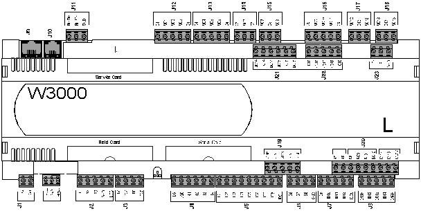
7 UNIT L UNIT XL 7
8 EXPANSION E W3000 8


9 3.2 Connecting more than one unit Caution: perform the following operations before touching the cards in order to prevent electrostatic discharge: wear the bracelet (connected to the earth circuit) and the heel strap the card should be closed inside an antistatic bag protecting it from electrostatic discharge: remove it from the bag and place it on the light-blue mat with the yellow edge or on the dark-blue mat. You can now work on the card. Several intercommunicating cards can be connected together on units L or XL. There are two connection types: base-expansion on the expansion serial line and master-slave on the plan serial line. The mixed connection is a combination of the other two. Details are shown below BASE-EXPANSION CONNECTION In the base-expansion connection, the entire intelligence of the unit resides in the base. The connected expansions are exclusively used as additional I/O. The cards must be connected together with a threewire shielded cable connected from terminal J23 of the base to terminal J3 of expansion E or to terminal J11 of expansion M (see figure 3.1). Figure 3.1: base-expansion connection The expansions must be given a specific address depending on the type of chiller and the enabled functions: 9
10 EXPANSIONS FOR HERMETIC COMPRESSORS: Additional function Function, chiller type Expansion address Expansion type Recovery enable Chiller with heat recovery 1 E Recovery enable Multi-use Heat pump with total heat recovery 2 M Freecooling enable HP relay enable Freecooling chiller Chiller with HP relay Low temperature control enable Low temperature chiller Low pressure transducer enable Any chiller with hermetic 3 E compressors where low pressure monitoring is required Number of compressors for circuit 3 or 4 Chiller with 3 or 4 hermetic compressors per circuit 4 E EXPANSIONS FOR SEMI-HERMETIC COMPRESSORS: Additional function Function, chiller type Expansion address Expansion type Recovery enable Chiller with heat recovery 1 E Recovery enable Multi-use Heat pump with total heat recovery 2 M Freecooling enable HP relay enable Setpoint variation enable Recovery setpoint variation enable Secondary setpoint enable Freecooling chiller Chiller with HP relay Unit with setpoint or secondary setpoint enable 3 E Number of evaporators 0 Number of compressors per circuit 2 At least one pump enable Heat pump Recovery enable Freecooling enable HP relay enable Low temperature control enable 2 evaporators Condensing units Unit with 2 alternative compressors per circuit Chiller with pumps on card Heat pump chiller Chiller with heat recovery Freecooling chiller Chiller with HP relay Low temperature chiller Chiller with more than one evaporator 4 E 5 E EXPANSIONS FOR CENTRIFUGE COMPRESSORS: Additional function Function, chiller type Expansion address Setpoint variation enable Unit with setpoint or secondary Secondary setpoint enable setpoint enable Expansion type 3 E 10

11 3.2.2 MASTER-SLAVE CONNECTION Intelligence is distributed instead in the masterslave connections. Suppose we have a unit with 4 cooling circuits: the master card manages circuits 1 and 2 while the slave card manages circuits 3 and 4. In this case, the additional card is not simply an input/output expansion, but is fully involved managing part of the unit. The card software is the same and identifies its functions depending on the card address: the one with address 1 will be the master and will communicate with the card with address 11 (master address plus 10). Pay special attention to card addresses for this reason. Connect the cards together with a 3-wire shielded cable connected between terminals J11 of the cards, as shown in figure 3.2. Figure 3.2: master-slave connection 11

.")
12 3.2.3 MIXED CONNECTION: The mixed connection is used in units with 3/4 cooling circuits where an increase in inputs/outputs is required. The master card manages circuits 1 and 2 while the slave card manages circuits 3 and 4. Additionally, depending on the required functions or the type of machine, cards used simply as expansions can be connected. The expansions will be connected to both the master and the slave if the required inputs/outputs are circuit functions (recovery valves, freecooling, ). They will only be connected to the master if they are machine functions (pumps, external air temperature, ). Figure 3.3 shows the connections between the cards and the expansions: a 3-wire shielded cable connects terminals J11 of the master and slave cards, and a 3-wire shielded cable connects terminals J23 of the master and/or slave cards with terminal J3 or J11 of expansions E or M. Figure 3.3: mixed connection 12
13 3.3 Additional connections In this case set the card address with the following dip-switches: ON DIP ON DIP Cards L, XL Cards E Table of possible combinations: (0 = off, 1= on) Address
14 3.4 Configuring the terminals The first operation to perform when a network is started up for the first time or a card is replaced, is to perform the procedure for terminal configuration. This cannot be achieved with the basic W3000 keypad. In this case, configure the terminals using the W3000 or W3000 compact keypad and then connect the W3000 basic display. Before starting, it is advisable to check that each card and each terminal has been identified with the correct address established when the network was designed. It is important to remember that as the set address is only read by the boards during startup, it is best to perform a global reset of all the devices if a mistake is made when configuring the addresses (more than one card with the same address). Reset the network by disconnecting all the devices from the power supply. The configuration procedure can be activated from any terminal (keypad), which may also be connected temporarily only to perform configuration operations and removed upon completion. The operations to perform are described in the following paragraphs SETTING THE KEYPAD ADDRESS After connecting the keypad to the device, perform the following procedure: 1) Press [UP], [DOWN] and [ENTER] together and hold down until the mask shown to the side appears. 2) Press [ENTER] to move the cursor to Display address setting. Press [UP] and [DOWN] to set the required keypad address (e.g.: 21 ). Display address Setting...:00 I/O Card address: Display address Setting...:21 I/O Card address:-- 3) This mask means that the address of the keypad has been set. Display address changed 4) If an empty mask or a mask showing NO LINK appears after pressing [ESC], it means that the keypad is not communicating with any card. Either the card must be addressed or the plan network must be configured. NO LINK N.B.: This is a timed procedure; if the parameters are not set within a few seconds, the display turns off. In this case, the operation must be repeated. 14
15 3.4.2 SETTING CARD ADDRESSES The card address is set by the software using the keypad. Proceed as follows: 1 Make sure the keypad address is set to 0 ( see para 3.4.1). Display address Setting...:00 2 Disconnect the card from the power supply (turn off the general switch). I/O Card address: 3 Power the card by pressing [ALARM] and [UP] together; hold the keys down until the mask shown to the side appears. 4 Set the required address (e.g.: 1 ) To do this, press [UP] or [DOWN]; press [ENTER] to confirm. 5 An empty mask appears because the address of the keyboard is 0 and that of the board is (as shown in the example) 1; the two devices cannot communicate. In any case, card address 1 has been set. 6 Now perform NETWORK CONFIGURATION to allow the card to communicate with its keypad plan address: 0 UP: increase DOWN: decrease ENTER: save & exit plan address: 1 UP: increase DOWN: decrease ENTER: save & exit 15
16 3.4.3 CONFIGURING THE PLAN NETWORK CONFIGURING THE PLAN NETWORK (local): For each unit with an on-board keyboard, perform the following procedure to create a locale plan network: 0 Make sure the card has been addressed (see para 3.4.2). plan address: 1 UP: increase DOWN: decrease ENTER: save & exit 1 Press [UP], [DOWN] and [ENTER] together and hold down until the Display address mask shown to the side appears. Setting...:00 I/O Card address: 2 Set the required address for the keypad (e.g.: 21 ) Display address Setting...:21 I/O Card address:-- 3 Press [ENTER] to display the address of the cards in plan (in this Display address case 1 ). Setting...:21 N.B.: If there is more than one card, press [UP] or [DOWN] to choose which card to configure. I/O Card address:01 4 Press [ENTER] to configure the terminals; press [ENTER] to confirm Terminal config Press ENTER To continue 5 In this mask, the [ENTER] key moves the cursor from one field to another and the [UP] or [DOWN] keys change the values. P:01 means that the card with address 1 is being configured. 6 Configure keyboard 21 (previously set) as Pr=private (usually the one on the unit). (Sp=printer, or Sh=shared) 7 The remote keypad must also be configured. Simply define the keypad addressed with 32 (even if not present) as Sh. 8 To save the settings and exit the configuration procedure, move the cursor to No, change it to Yes and press [ENTER]. To exit without saving the settings, wait 30 seconds without touching the keypad. 9 The following mask may appear. If no expansions are connected, simply press [ESC] to show the main display menu. P:01 Adr Priv/Shared Trm1 None -- Trm2 None -- Trm3 None -- Ok?No P:01 Adr Priv/Shared Trm1 21 Pr Trm2 None -- Trm3 None -- Ok?No P:01 Adr Priv/Shared Trm1 21 Pr Trm2 32 Sh Trm3 None -- Ok?No P:01 Adr Priv/Shared Trm1 21 Pr Trm2 32 Sh Trm3 None -- Ok?Yes ##################### expansion connection ##################### To connect several units together and remote control them, thereby forming a plan network (global), a remote keypad controlling all the units is required. The remote keypad cannot be used with a W3000 basic keypad. If a W3000 basic keypad is installed on the machine, replace it with a 3000 compact. 16
17 CONFIGURING THE PLAN NETWORK (global): It is easy to install a PLAN network (global). Just a few but essential operations are required. If just one of these is not performed correctly, the entire system will not work. The remote keypad will work problem-free if the following operations are performed one after the other. 1 Set the on-board machine card and keypad addresses (see configuring the local plan network) 2 Check the chillers work correctly without being connected to the network. 3 Disconnect the power supply from the chillers Leaving the network cable disconnected. configure the terminals on each card and keypad (J11 connector) 4 Connect all the chillers to the network except for the remote keypad. 5 Power the chillers. 6 Check that all the networked devices work correctly Connect connectors J11 together. Do not connect the remote keyboard. This creates a plan network comprising more than one chiller. If any faults occur, check the configuration of the terminals to make sure that no two devices have the same address. 7 Connect the remote keypad to one of the units Disconnect the machine keyboard and connect the remote keypad to the J10 connector. 8 Make sure the remote keypad address is set to Make sure that the devices outside the chillers are correctly configured. Follow the procedure for addressing the keyboard (see para 3.4.1). If the power unit for the remote keypad is fitted (see below: remote keypad from 200 up to 500 metres), make sure the remote keypad is powered. 11 Connect the remote keyboard. Disconnect connector J10 from the last board and connect it to connector A of the T shunt. Connect connector J10 on the last board to connector B of the T shunt. 10 Wait a few seconds until network communication has stabilised. If there is global network comprising just W3000 chillers, the W3000-compact can be used as a remote keyboard. After configuring the various units (each with a different address in order not to generate conflicts in the global network), connect the remote keyboard and repeat the procedure. In this case, the various machines of the network are switched by pressing [ESC] and [UP] together. If the plan network does not comprise just W3000 chillers, a 16-key keypad must be used. In this case, press [UNIT] to switch between one card and another. In this case, however, the terminals must be given a special configuration as the 16-key keypad is only recognised on terminal 3. The terminal configuration procedure remains the same up to point 6 of paragraph 3.4.5, after which: 7 The remote keypad can be configured even if the plan network doe not comprise just W3000 chillers. Simply define the keypad addressed with 32 (N.B.: on terminal 3) as Sh, i.e.: shared. 8 To save the settings and exit the configuration procedure, move the cursor to No, change it to Yes and press [ENTER]. To exit without saving the settings, wait 30 seconds without touching the keypad. P:01 Adr Priv/Shared Trm1 21 Pr Trm2 None -- Trm3 32 Sh Ok?No P:01 Adr Priv/Shared Trm1 21 Pr Trm2 None -- Trm3 32 Sh Ok?Yes 17
18 CONNECTING THE REMOTE KEYPAD: T SHUNT: Let us analyse a vital component for connecting several units in a network: the T shunt. This is a shunt with phone connectors (called A,B,C in figure 3.4b). Figure 3.4a: photo of a T shunt CONFIGURATION: For our purposes, configure terminals J14 and J15 (see Figure 3.4b). There are several pins in each terminal. Short pins 1 and 2 with a jumper. Figure 3.4b: wiring diagram of a T shunt Screw terminal Function 0 Earth (sheath of shielded cable) 1 +VRL=30V 2 GND 3 Rx+/Tx+ 4 Rx+/Tx+ 5 GND 6 +VRL=30V Figure 3.4c: terminal card of a T shunt T REMOTE KEYPAD UP TO 200 metres: To connect a remote keypad, two T shunt cards must be used, one near the controller and the other near the remote keypad, configured as indicated above. The T shunt cards must be connected together by terminals. 1. If the remote keypad monitors just one unit, proceed as follows: Disconnect the connector J10 connecting the keypad on the unit with the card, and connect it to connector A of the T shunt (see figure 3.5). Connect connector J10 on the card to connector B of the T shunt. The correct configuration is shown in figure 3.5: 18
19 SHIELDED TWISTED Figure 3.5 : connecting the remote keypad (for distances less than 200 metres) 2. If a remote keypad monitors more than one unit, the above configuration may only be used for the last card in the network (the nearest to the remote keypad). REMOTE KEYPAD FROM 200 metres UP TO 500 metres N.B.: The remote keypad cannot be installed more than 500 m away. If the remote keypad must be installed over 200 metres away from the plan network, a power unit must be installed near the remote keypad. The only difference between this and a remote keypad up to 200 metres is that the power unit must be to terminals 1 and 2 of the T shunt (the one near the remote keypad) The connection diagram is: 19
20 SHIELDED TWISTED Figure 3.6: connecting the remote keypad (for distances between 200 and 500 metres) 20
21 4 SWITCHING THE UNIT ON AND OFF Caution: connect the unit to the power supply at least 8 hours before starting it; if this is not done, the guarantee will become null and void. After making connections (see chapter 3) there are different procedures for starting or stopping the unit: using the user interface keys or selecting from the display. The following procedures have a priority. In the event of conflicts between different settings, the following priorities apply: - highest priority: on/off from keypad on/off from parameter on/off from digital input on/off from time bands - lowest priority: on/off from protocol using the [ON/OFF] key : The unit can only be switched off in the W3000 and W3000 base versions. Proceed as follows: SWITCHING ON: press the [ON-OFF] key. SWITCHING OFF: press the [ON-OFF] key. In the W3000, the message Com. : ON appears on the display In the W3000 base, the message On appears on the display with the LED on, or OFF with the LED off. using the On/Off parameter: Only in the W3000 and W3000 compact. The Com: On/Off parameter can be displayed on the user interface. Off means that the unit is switched off while On means that the unit is switched on. Proceed as follows: SWITCHING ON: Move to the On/Off parameter by pressing [Enter] and then press [Up] or [Down] until On appears. Press [Enter] again to confirm. If On continues to be displayed it means that the unit has been switched on. SWITCHING OFF: Move to the On/Off parameter and change to Off using the same procedure used to switch the unit on. Press [Enter] again to confirm. If Off continues to be displayed it means that the unit has been switched on. using the On/Off from digital input command: Only if the digital input is present (or an additional button on the user interface). Check that the On/Off enable from digital input parameter in the user menu is set to Yes. When the contact is open the unit is Off, when the contact is closed the unit is On. Proceed as follows: SWITCHING ON: Close the remote On/Off contact. The On from digital input message appears in the main mask to show that the unit has been switched on. SWITCHING OFF: Open the remote On/Off contact. The Off from digital input message appears in the main mask to show that the unit has been switched off. In the W3000 base the following procedure is used: press [MENU] / select the User menu using the [UP] or [DOWN] keys / press [ENTER] to access the menu / press enter to type in the password / press [UP] or [DOWN] to choose the password and [ENTER] to confirm / use the [UP] or [DOWN] keys to choose the di 0 (Enable from digital input) mask / press [ENTER] to view 21
22 the current setting of the parameter ( Y or N ) / press [ENTER] to modify the parameter (the display flashes) / press [UP] or [DOWN] to select one of the two alternatives. Press the digital input button on the panel to switch the unit on and off. using time bands: Only in the W3000 and W3000 compact and if the clock card is present. Make sure that the Clock card not installed mask does not appear in the clock menu. Check that the Time bands enable parameter in the user menu is set to Yes. SWITCHING ON: Set the required switching on time in the clock menu. The unit switches on when the set time is reached. The On from time bands message appears in the main mask to show that the unit has been switched on. NB.: The unit does not switch on if it is set to Off from keypad or Off from digital input. SWITCHING OFF: Set the required switching off time in the clock menu. The unit switches off when the set time is reached. The Off from time bands message appears in the main mask to show that the unit has been switched off. using the supervision protocol: Only if the serial card is fitted. Check that the Supervisor enable and On/Off enable from supervisor parameters in the user menu are set to Yes. Proceed as follows: SWITCHING ON: Send the switching on command from the protocol. The On from supervisor message appears in the main mask to show that the unit has been switched on. NB.: The unit does not switch on if it is set to Off from keypad or Off from digital input. SWITCHING OFF: Send the switching off command from the protocol. The Off from supervisor message appears in the main mask to show that the unit has been switched off. In the W3000 base the following procedure is used: press [MENU] / select the User menu using the [UP] or [DOWN] keys / press [ENTER] to access the menu / press enter to type in the password / press [UP] or [DOWN] to choose the password and [ENTER] to confirm / use the [UP] or [DOWN] keys to choose the SPr (Enable from supervisor) mask / press [ENTER] to view the current setting / press [ENTER] to see the display flashing / press [UP] or [DOWN] to modify the setting and press [ENTER] to confirm. 22
23 5 USER PROGRAMMING The following settings can be modified using the interface. 5.1) SETTING THE OPERATING MODE Caution: Do not switch from the summer to winter mode unless the inlet temperature is above 15 C. Do not switch from the winter to summer mode unless the inlet water temperature is below 30 C. There are various ways of setting the operating mode of the unit. The set operating mode may be any one of the following, as long as they are compatible with the unit: Operating mode Description W3000 base Chiller ch Chiller chiller+rec Chiller plus recovery heatpump hp Heat pump summer ch Chiller in summer mode summer ch+rec Chiller plus recovery in summer mode summer rec Recovery in summer mode recovery Recovery only summer auto Automatic in summer mode winter hp Heat pump in winter mode winter rec Recovery in winter mode winter auto Automatic in winter mode auto Automatic The following procedures have a priority: in the event of conflicts between opposing settings the following priorities apply: - highest priority: change through parameter sum/win from digital input ch/ch+rec from digital input - lowest priority: change through protocol Using the parameter: Make sure the unit is Off. Access the setpoint menu and display the Operating mode parameter. Move to the Operating mode parameter by pressing [Enter] and modify the parameter by pressing [Up] or [Down]. Press [Enter] again to confirm. If the set message continues to be displayed it means that operating mode has been changed. In the W3000 base the key sequence is: switch off the unit using the [ON/OFF] key / press the [setpoint] key / select MODE with the [UP] or [DOWN] keys / press [Enter] / press [Enter]. At this point the cursor flashes. Press the [UP] or [DOWN] keys to select either ch = chiller or hp = heat pump. Press [Enter] to confirm. Using the Sum/Winter from digital input command: Only for heat pump units and only if the digital input is present. Check that the Sum/Win enable from digital input parameter in the user menu is set to Yes. When the contact is open the unit is in the winter mode, when the contact is closed the unit is in the summer mode. Switching the digital input switches the unit off, changes the operating mode and switches the unit on again. 23
24 In the W3000 base access the user menu / select DI S by pressing the [UP or DOWN] key/ press [Enter] to view the current setting / press [Enter] to see the current setting flashing and change it using the [UP or DOWN] key / press [Enter] to confirm the new setting. Using the recovery from digital input command: Only for chiller plus recovery units and only if the digital input is present. This mode is not present in the W3000 base. Proceed as follows: check that the Recovery control enable from digital input parameter in the Recovery menu is set to Yes. When the contact is open the unit is in the chiller+rec mode, when the contact is closed the unit is in the chiller mode. Switching the digital input switches the unit off, changes the operating mode and switches the unit on again. Using the supervision protocol: Only applicable if the serial card is fitted. Check that the Supervisor enable and Enable operating mode from supervisor parameters in the user menu are set to Yes. Make sure the unit is Off. Send the change operating mode command from the protocol. The operating mode only changes if the unit is switched off. In the W3000 base press [ON/OFF] to switch the unit off. Access the user menu / press [UP] or [DOWN] to select SV M / press [Enter] to view the set mode / press [Enter] to see the setting flashing / press [UP] or [DOWN] to modify the setting / press [Enter] to confirm the new setting. Send the change operating mode command from the protocol. The operating mode only changes if the unit is switched off. 24
25 5.2) USER MENU The user menu is used to display and set important operating, adjustment, setpoint and recovery parameters. The physical principles lying at the heart of some special functions are described below ) ADJUSTMENT Depending on the type of hardware and the type of compressor used, a choice may be made (for inlet or outlet temperature) between STEP and QUICK MIND adjustment. N.B.: some functions, such as setting the compressor type and modulating adjustment, can only be set from the manufacturer menu. XL Hardware Other Hardware Hermetic compressor Step adjustment (inlet only) Quick Mind adjustment (outlet only) Alternative compressor Step adjustment (inlet only) Quick Mind adjustment (outlet only) Screw compressor Step adjustment (inlet only) Quick Mind adjustment (outlet only) Modulating adjustment (Quick mind for outlet required) Centrifuge compressor Proportional step adjustment for inlet and integral for outlet Table 5.3: adjustment types depending on the type of hardware and the type of compressor The various adjustment methods are shown in detail below. STEP INLET ADJUSTMENT METHOD: The procedure for accessing step inlet adjustment is shown in the parameters annex. The step inlet adjustment type and adjustment band can be set from the relative parameters in the user menu. Some examples of step adjustment for the input variable (inlet temperature) are shown below. Figures 5.1 and 5.2 show the graphs of the variable controlled according to the power delivered by the machine for two typical cases. 25
26 summer ( n steps=2 ) P out T in proportional band Figure 5.1: T in is the inlet variable, P out is the percentage of delivered power (summer). = Set + proportional band/2 Winter (n steps = 2) P out T in proportional band Figure 5.2: T in is the inlet variable, P out is the percentage of delivered power (winter). = Set + proportional band/2 Table 5.1 and 5.2 show some typical values for the parameters in question. The theoretical maximum and minimum outlet temperature values refer to operation at nominal flow rates ( with a thermal head at the evaporator of 5 C and sufficient water in the system to ensure a litre / KW ratio equal to or greater than 11). N steps Setpoint ( C) Proportional band ( C) Theoretical min. outlet T Theoretical max. outlet T Table 5.1: normally used setpoint and proportional band values according to the number of steps (summer). 26
27 N steps Setpoint ( C) Proportional band ( C) Theoretical min. outlet T Table 5.2: normally used setpoint and proportional band values according to the number of steps (winter). Theoretical max. outlet T QUICK MIND ADJUSTMENT METHOD: QUICK MIND adjustment is not available on chillers with recovery or freecooling or multi-purpose. QUICK MIND adjustment is currently only possible on outlet water temperature. Users only need set the required setpoint as the other parameters are adapted to the system by the Quick Mind algorithm. The values normally used are: Chiller SETPOINT 7 C Heat pump SETPOINT 45 C QUICK MIND is a self-adapting algorithm for adjusting the temperature of the water treated by a chiller. Figure 5.3 shows how this adjustment is made: SUMMER ESTATE Compressors Disattivazione deactivated compressori ZONA DEAD NEUTRA AREA Compressors Attivazione compressori activated Tin/Tout Setpoint WINTER INVERNO Compressors Attivazione compressori activated Compressors Disattivazione deactivated compressori ZONA DEAD NEUTRA AREA Tin/Tout Setpoint Figure 5.3: QUICK MIND adjustment model (summer and winter) The setpoint remains within a dead area. If the temperature also remains within this area, no change is made to the number of active compressors. When the temperature leaves the dead area following a change in system load, the compressors are either activated or deactivated in order to return the temperature to the dead area. The amplitude of the dead area depends on the dynamic characteristics of the system and, in particular, on the amount of water it contains and the load. The self-adapting algorithm is able to measure system dynamics and calculate the minimum dead area in order to respect compressor activation times and the maximum number of start-ups per hour. Both return and delivery temperatures can be adjusted. Special functions are also present which reduce the number of compressor start-ups in the event of very low loads or start-ups of units with significantly higher or lower temperatures than the setpoint. 27

28 2 compressors - with maximum permitted number of start-ups per hour 8 Litres/kW Τout compressors - with maximum permitted number of start-ups per hour 12 Litres/kW Τout compressors - with maximum permitted number of start-ups per hour 8 Litres/kW Τout compressors - with maximum permitted number of start-ups per hour 12 Litres/kW Τout Table 5.3: maximum theoretical delivery temperature range at constant part load (depending on the quantity of water contained in the system) An example of real data acquired during operation with the Quick Mind adjuster on the delivery side is shown below. Reference is made to figure 5.4. Fase di avviamento controllato = Controlled starting phase Adattamento zona neutra = Adaptation to dead area Temperatura uscita evaporatore = Outlet temperature of evaporator Temperatura ingresso evaporatore = Inlet temperature of evaporator 1 compressore attivo = 1 compressor active 2 compressori attivi = 2 compressors active Figure 5.4: example of real data with quick-mind outlet adjustment (x-axis: time in [s]; y-axis: Tout in [ C] ). This is an example of start-up with a very high initial temperature compared with the setpoint (7 C). About 10 seconds after data acquisition began, one compressor switches on. The second compressor does not switch on immediately as the algorithm which handles start-up checks if one compressor is enough to return delivery temperature to the setpoint and avoid unnecessary start-ups. As the delivery temperature is still at 12 C after about 200 seconds, the second compressor is also switched on, otherwise it would take too long to reach setpoint. Following the controlled starting phase, the delivery temperature falls until it enters the dead area. The algorithm (at t= 350 s) begins to adapt the amplitude of the dead area in order to respect compressor safety times. As can be seen, the dead area is later reduced (t= 780 s, 950 s) to the absolute minimum amplitude which allows safety times to be respected. It can also be seen that the compressors are 28
29 activated and deactivated when the outlet temperature reaches the upper or lower limits of the dead area. The example shows that outlet temperature varies by about 3.5 C during regular operation. ADJUSTMENT METHOD FOR CENTRIFUGE COMPRESSORS: The W3000 controller can manage units with centrifuge compressors. The units are combination-adjusted (steps and continuously), with steps for activating the compressors. Some diagrams outlining how this works are shown below. Suppose we have a single compressor unit (figure 5.5). Absorbed Potenza assorbita power [kw] [Kw] Max Min Thermoregulator Potenza power richiesta request del termoregolatore [%] [% ] set point (0% ) % accensione compressor compressore switch-on Set Set point + Banda Prop. proporzionale band (100%) (100%) Figure 5.5: adjustment for a single-compressor unit. Min=theoretical minimum electrical power absorbed by a compressor, Max=theoretical maximum electrical power absorbed by a compressor Let us take a close look at how the compressor is activated (figure 5.6). When the system return temperature lies in zone A (figure 5.6a) or less than the setpoint, the compressor is off. The amplitude of zone A normally coincides with the temperature difference at the evaporator with the compressor running at minimum power. When the return temperature exceeds zone A (figure 5.6b), the compressor is switched on and then switches off if the temperature falls below the setpoint. If the return temperature lies in zone B (figure 5.6c), the power of the compressor is modulated according to system requirements. set point + proportional band Tin [ C] set point + proportional band Tin [ C] start compressor 1 set point A t [min] start compressor 1 set point A t [min] ON ON OFF OFF Figure 5.6 a) Figure 5.6 b) 29
30 set point + proportional band Tin [ C] B start com pressor 1 set point t [m in ] ON OFF max Pass [Kw] min Figure 5.6 c) Suppose we have a unit with more than one compressor (figure 5.7). Absorbed Potenza assorbita power [Kw] Max 2x Min Min set point (0%) % compressor % accensione1 1 compressore switch-on % compressor % accensione 2 2 switch-on compressore Set point + Banda prop. proporzionale band (100 (100 %) %) Thermoregulator Potenza power Request richiesta del [%] termoregolatore [%] Figure 5.7: adjustment for a two-compressor unit. Min=theoretical minimum electrical power absorbed by a compressor, Max=theoretical maximum electrical power absorbed by a compressor. Let us take a close look at how the compressor is activated (figure 5.8). The amplitude of zone A coincides with the temperature difference at the evaporator, with all the compressors running at minimum power. Zone A is the sum of the zones of each single compressor (A1+A2+ ). When the temperature lies in one of the An zones, the power of the active compressors is modulated according to system requirements. When moving from an An zone to the one just above it, the active compressors are taken to minimum power while waiting for the next one to be switched on. After that, they continue to be modulated in the new zone. When moving from an An zone to the one just below it, one of the compressors is switched off while the others are kept at a minimum. 30
31 ssetpoint e t p o t + b a nproportional d a p r o p o r zband i o n a l e T in [ C ] B s t a start r t 2 compressor c o m p r e s s 2 o r e s t a start r t 1 compressor c o m p r e s s 1 o r e s e t p o in t A 2 A 1 A m a x P a s s [ K w ] t [m in ] C o m p r. 1 m i n m a x P a s s [ K w ] C o m p r. 2 m in Figure 5.8: adjustment for a two-compressor unit CONTINUOUS ADJUSTMENT METHOD FOR SCREW COMPRESSORS (modulating adjustment) In screw compressors, modulating adjustment requires Quick mind outlet adjustment. Modulating adjustment is only available on Bitzer screw compressors. set point Tout [ C] ZN DA B (increase) (incremento) t [min] C (decremento) (decrease) Reference is made to figure 5.9. The setpoint remains within a dead area. If the temperature also remains within this zone, no change is made to the number of active compressors or their load percentages (position of modulating chamber). When the temperature rises above zone B following a change in the system load, the compressors are activated in order to return the temperature to the dead area. Inside zone B, compressor power is modulated to return the temperature to the dead area (DA). Figure 5.9: adjustment for screw compressors When the temperature falls below zone C following a change in the system load, the compressors are either deactivated in order to return the temperature to the dead area. Inside zone C, compressor power is modulated to return the temperature to the dead area (DA). The amplitude of the dead area depends on the dynamic characteristics of the system and, in particular, on the amount of water it contains and the load. The self-adapting algorithm is able to measure system dynamics and calculate the minimum dead area in order to respect compressor activation times and the maximum number of start-ups per hour ) RECOVERY The user menu can be used to set certain recovery parameters, such as the recovery adjustment band and the recovery setpoint. 31
32 100% 75% 50% 25% Banda Recovery regolazione adjustment recupero band T.Rec [ C] Figure 5.10: recovery function of a 4-circuit unit Recovery Setpoint setpoint recupero 32
. 5.")

33 5.3) SETPOINT MENU Different setpoints can be set depending on the available operating modes (chiller, heat pump and recovery). Secondary setpoint values can also be set for chiller and heat pump operation (only if the digital input is fitted and the secondary setpoint function is enabled in the user menu ). 5.4) CLOCK MENU The clock menu is not enabled in the W3000 base. After enabling time bands from the enable time bands parameter in the user menu, time bands can be set and specific operating modes and different setpoints can be set according to requirements. Several time bands (up to 10) of different types (A, B, C and D) can be set during the day. Figure 5.11 shows an example: the beginning of the first time band is set at 00:00 and the end of the tenth time band is set at 23:59; the end of one time band determines the beginning of the following one. To use a smaller number of bands, set the time a band ends to the same time it begins, and that band will be ignored. Summer and winter setpoints and unit On/Off switching can be set for each time band. If the unit is switched Off, it will remain in the Off from time bands mode. Adjustment Unit off Figure 5.11: example of setting time bands 33
34 6 MANUFACTURER PROGRAMMING The manufacturer menu is not present in the W3000 base. For the other user interfaces, instead, access the manufacturer menu by pressing [Menu] / selecting the manufacturer menu by pressing [UP] / entering the password. The tree diagram of the manufacturer menu is shown in figure 6.1. Selezione Manufacturer Menù Menu costruttore selection Esc Menù Manufacturer costruttore menu Esc Configuration Selezione menu Menù configurazione selection Esc / Menù Configuration configurazione menu Esc Selezione Global menu Menù selection globale Esc / Menù Global globale menu Esc Functions Selezione menu Menù selection funzioni Esc / Menù Functions funzioni menu Esc Pumps Selezione menu Menù selection pom pe Esc / Menù Pumps pom menu pe Esc Compressors Selezione menu Menù selection com pressori Esc / Menù Compressors com pressori menu Esc Selezione Valves menu Menù selection valvole Esc / Menù Valves valvole menu Esc Recovery Selezione menu Menù selection recupero Esc / Menù Recovery recupero menu Esc Condensation Selezione menu Menù condensazione selection Esc / Menù Condensation condensazione menu Esc Freecooling Selezione menu Menù selection freecooling Esc / Menù Freecooling freecooling menu Esc Defrosting Selezione menu Menù selection sbrinam ento Esc / Menù Defrosting sbrinam menu ento Esc Selezione Alarms menu Menù selection sicurezze Esc / Menù Alarms sicurezze menu Esc Calibration Selezione menu Menù selection taratura Esc / Menù Calibration taratura menu Esc Assistance Selezione menu Menù selection assistenza Esc / Menù Assistance assistenza menu Esc Initialisation Selezione menu Menù inizializzazione selection Esc / M e ninitialisation ù in izia lizza menu zio n e Figure 6.1 : manufacturer menu tree diagram Some important parameters that can be set from the manufacturer menu are shown below. 34
35 6.1) FREECOOLING The freecooling function is applied to the efficient production of cold water by using external air. The operating principle is illustrated in figure 6.2. air FREECOOLING COIL EVAPORATOR 3-way valve water Figure 6.2: block diagram of the freecooling activation circuit If the external water is cold, the valve closes and the water passes through the coil which cool the water by the water-air heat exchange achieved thanks to the internal fans. If, instead, the air is hot, there is no point in it passing through the coil and all the water is cooled with the evaporator compressors. Further details of the valve and fan adjustment system are shown in figures 6.3. % v a lv e aperture - O n /O ff va lve - M odulating valve 100% T ext. Delta T fcool. Figure 6.3a: valve operation - On/Off valve - Modulating valve % valve aperture 100% T. in Diff. Offset Chiller setpoint Figure 6.3b: freecooling low temperature control (to prevent the coil from freezing) 35
36 step n Step speed adjustment % demand Dynamic setpoint Dynamic freecooling band T. in Chiller setpoint Figure 6.3c: fan adjustment in the step mode (example with 8 fans) 100% Continuous speed adjustment % demand Dynamic setpoint Dynamic freecooling band T. in Chiller setpoint Figure 6.3d: fan adjustment in the continuous mode 6.2) CONDENSATION Condensation adjustment depends on how the fans are turned on. Various condensation adjustment types in the chiller operating mode are shown below. The fans may be turned on using the on/off system ( step ) in which the fans are turned on progressively one after the other (figure 6.4a) or mutually excluded (figure 6.4b). Fans switched on in parallel but that increase fan speed (depending on pressure) are illustrated in figure 6.4c). Active steps Continuous step adjustment Step4 on 3 Step3 on Set Point - differential Set Point 2 Step2 on Set Point - differential Set Point 1 Step1 on Set Point - differential Set Point Set Point - differential Set Point Pressure Figure 6.4a: continuous step condensation adjustment 36
37 Active steps Step adjustment 1 Step1 on Step2 on Step3 on Step4 on Set Point - differential Set Point Set Point - differential Set Point Set Point - differential Set Point Set Point - differential Pressure Set Point Figure 6.4b: step condensation adjustment Condensation Continuous adjustment 100% max speed % Condensation without Off adjustment min speed % Condensation with Off adjustment Set Point - diff. Off Set Point Figure 6.4c: continuous condensation adjustment Set Point + differential Pressure 37
38 7 ALARMS Press the [ALARM] key once to enter the alarms menu and view the alarm message along with its code. If there is more than one alarm, scroll the menu using the [UP] and [DOWN] keys. In the W3000 base, NO A is displayed if there is no alarm, otherwise the alarm code appears. Press any other key to exit from this menu. The only thing the user can to is to reset the alarm. To reset the alarm press the [ALARM] key again and hold it down until the message No Alarm Active (for W3000 or W3000 compact) or No A (for W3000 base) appears. If the message does not appear it means that one or more alarm conditions are still active. alarms table ALARM DESCRIPTION details RESET Faulty phase connection. Totally shuts down the unit (only displayed if the input that detects it is A 002 Phase sequence fitted) 003 Evaporator flow switch In units with hardware that does not distinguish between flow switch and thermal protection, this alarm trips when the pump motor overheats or if there is no flow to the evaporator. The alarm automatically resets if there is no flow but must be manually reset (on the pump) if the A pump has overheated. Only displayed if the digital input is separate from the evaporator pump thermal protection. No flow to evaporator. 005 Low inlet temperature Enabled only in the heat pump mode. Low water temperature at evaporator inlet. S-A 006 High inlet temperature Enabled only in the chiller mode. High water temperature at evaporator inlet. S-A 010 Evaporator antifreeze Low water temperature at evaporator outlet. Also specifies (except for W3000 base) which evaporator (if more than one) is involved in the M alarm condition. 014 No enable signal Only displayed if the relative input is present (see I/O menu). Unit stops due to an external signal. M 021 Low water charge The evaporator outlet temperature changes too quickly and creates a low water level in the S system. 022 Low water flow The temperature difference between the evaporator inlet and outlet is too high and creates M a low water flow from the pump 023 High water flow The temperature difference between the evaporator inlet and outlet is too low and creates S a high water flow from the pump 045 Condenser flow switch No water flow to the condenser. A 046 Recuperator flow switch No water flow to the recuperator. A 051 Pump 1 maintenance Maintenance hours limit exceeded (in units with just 1 pump, pump 1 is the evaporator pump) S 052 Pump 2 maintenance Pump 2 maintenance hours limit exceeded (in units with more than one pump). S 075 Condenser antifreeze Low water temperature at condenser outlet. Except for W3000 base, it also specifies which condenser (if more than one) is involved in the M alarm condition. 076 Recuperator antifreeze Risk of freezing on recuperator exchanger. A 081 Pump 1 thermal protection Pump 1 overheated (in units with just 1 pump, pump 1 = evaporator pump) M 082 Pump 2 thermal protection Pump 2 overheated (in units with more than one pump). M 085 Condenser pump thermal protection Condenser pump overheated M 086 Recuperator pump thermal protection Recuperator pump overheated M 38
W3000 Second Edition
 W3000 Second Edition USER MANUAL C0240102-07-11-EN For software versions GA09 Replaces C0240102-04-11-EN E N The information contained in this document may be modified without prior notice. No part of
User manual. Standard Modular Chiller HP 1/8 compressors with CAREL driver Application program for pco 1, pco 2, pco 3, pco C and pco XS.
 Standard Modular Chiller HP 1/8 compressors with CAREL driver Application program for pco 1, pco 2, pco 3, pco C and pco XS. User manual Manual version: 2.4 dated 27/02/08 Program code: FLSTDmMCDE LEGGI
Service Manual Preliminary Version. MCQUAY MicroTech II Control plan+driver. for Modular Chillers
 MCQUAY plan+driver for Modular Chillers McQuay ALS / WHS / PFS With screw compressors, 1 to 4 circuits Release of the Manual: 1.0-01/05/2001 Contents APPLICATIONS AND FUNCTIONS CARRIED OUT BY THE SYSTEM...3
PCT-3000 plus DIGITAL PRESSURE CONTROLLER FOR COOLING PLANTS
 PCT plus DIGITAL PRESSURE CONTROLLER FOR COOLING PLANTS Ver. DESCRIPTION The PCT plus is a pressure controller for refrigeration plants that require control in their suction and discharge stages. With
PCT-3001 plus. Display LCD
 PCT3 plus DIGITAL PRESSURE CONTROLLER FOR COOLING PLANTS DESCRIPTION Pressure controller for refrigeration systems capable to control suction (compressors) and discharge (fans) pressures. It is possible
Temperature Controller OVATION 214 User's Guide
 Temperature Controller User's Guide Read this guide carefully before using the controller. 890-00045 rev.00 TABLE OF CONTENTS Page TABLE OF CONTENTS... 2 PRECAUTIONS... 3 FEATURES... 4 LOCATION OF THE
OMEGA V ECHOS Water/water cooled chillers and heat pumps kw
 Water/water cooled chillers and heat pumps 172 1527 kw General information Water-cooled water chillers with hermetic screw compressors and tube bundle heat exchangers. Designed for installation indoors.
Inlet Controller TC5-ITA USER'S MANUAL. M rev. 02 K rev. 00
 Inlet Controller TC5-ITA USER'S MANUAL M 890-00047 rev. 02 K 895-00458 rev. 00 TABLE OF CONTENTS PRECAUTIONS... 3 FEATURES... 4 LOCATION OF THE CONTROLS... 5 Status Leds...5 Internal Switches...6 INSTALLATION
Electronic Ballast EVG 2000-T
 Electronic Ballast EVG 2000-T Operating Manual Table of contents 1 Description 1.1 Advantages of this ballast... 3 1.2 Functional principle... 3 1.3 Energization... 4 1.4 Visualization... 5 1.5 Indications
ST48-WHUV.102. Wiring diagram. Product description. PID controller. Order number
 ST48-WHUV.12 PID controller Order number 935.15 Wiring diagram Product description This micro-processed controller serves for temperature control at high measuring accuracy. Beside resistance sensors and
VLH 504 to Air-to-Water Reverse Cycle Heat Pumps. 126 to 294 kw. 133 to 307 kw
 Air-to-Water Reverse Cycle Heat Pumps VLH 504 to 1204 126 to 294 kw 133 to 307 kw Technical Brochure TM VLH-N.3GB Date : June 2005 Supersedes : TM VLH-N.2GB/07.04 Specifications Advantages Range extension
Inlet Controller SB3500 USER'S MANUAL
 Inlet Controller USER'S MANUAL NOTICE Every effort has been made to ensure that this manual is complete, accurate and up-to-date. The information contained in it is however subject to change without notice
Parker AC10 Frequency Inverter (to 22kW) Easy Start Guide
 Easy Start Guide") Parker AC10 Frequency Inverter (to 22kW) Easy Start Guide CAUTION: 1)Do not re-set while the motor is rotating 2)Perform parts replacement after discharge is finished 3)Do not connect output terminals
Parker AC10 Frequency Inverter (to 22kW) Easy Start Guide CAUTION: 1)Do not re-set while the motor is rotating 2)Perform parts replacement after discharge is finished 3)Do not connect output terminals
NECS-WQ. Climaveneta Technical Bulletin NECS_WQ_0152_1604_201006_GB. INTEGRA unit for 4-pipe systems, water source ,6-522 kw
 Climaveneta Technical Bulletin NECS_WQ_0152_1604_201006_GB r HFC R-410A 0152-1604 48,6-522 kw INTEGRA unit for 4-pipe systems, water source (The photo of the unit is indicative and may change depending
RKE RKE FO RKE BF RHR SRS Series
 INSTRUCTIONS FOR USE OF ELECTRONIC CONTROL UNIT RKE RKE FO RKE BF RHR SRS Series Ed. 2/21 The manufacturer reserves the right to make alterations without notice Index 1. ELECTRONIC CONTROL UNIT page 3
XC1000 SERIES: up to 15 COMPRESSOR/FAN OUTPUT APPLICATIONS
 D: 1 DIN Rail VG: 82x156mm XC1 SERIES: up to 15 COMPRESSOR/FAN OUTPUT APPLICATIONS Electronic controllers for compressors and condensing fans management of medium-large compressor racks Scroll, semi-hermetic,
CWP. Cooling Only Version (CO) Condenserless Version (RC) Heat Pump Version (HP) Models 02 to 35. Engineering Data Manual. Water Cooled Water Chillers
 Condenserless Version (RC) Heat Pump Version (HP) Models 02 to 35. Engineering Data Manual. Water Cooled Water Chillers") Engineering Data Manual Water Cooled Water Chillers Cooling Only Version () Condenserless Version () Heat Pump Version () Models 02 to 35 8 to 136 9 to 164 N IRWELL GROUP MPNY Specifications General The
Engineering Data Manual Water Cooled Water Chillers Cooling Only Version () Condenserless Version () Heat Pump Version () Models 02 to 35 8 to 136 9 to 164 N IRWELL GROUP MPNY Specifications General The
CAM-PTZ-AUT Tracking Module for PTZ Camera Installation & User Manual
 CAM-PTZ-AUT Tracking Module for PTZ Camera Installation & User Manual i / iii Thank You for Choosing Aventura's CAM-PTZ-AUT Tracking Module for PTZ Cameras! When you open the box: Check that the packing
APP EOLE4. Applicable to program versions TAC5 Version DT & DG 2.7.0
 APP EOLE4 Applicable to program versions TAC5 Version DT 2.8.2 & DG 2.7.0 2 THE APP EOLE4 INTERFACE This interface can be used on Android, IOS and PC. Download the app from the App Store/Google Play or
RVD G2383en. Installation. - Compact station - Control cabinet (in the front, on the inner wall or on a
 4 319 2968 0 G2383en en Installation Instructions District heating controller for one heating circuit and d.h.w. RVD230 Installation Place of installation In a dry room, e.g. in the heat exchanger room
QUOTATION BLADE 7 LX. Product code GEAL6S2BAA
 1 of 10 Mattei rotary vane compressors are the result of 90 years of investments in research and development to improve performance and lessen the impact on the environment. Designed for industrial continuous
EXPERT 2V4SA. Temperature Controller. User s manual CLEAN MODE COMPENSATION HUMIDITY OUTSIDE TEMPERATURE
 CLEAN MODE Temperature Controller User s manual CURRENT CONDITIONS ROOM TEMPERATURE PROBE TEMPERATURE OUTSIDE TEMPERATURE RELATIVE HUMIDITY STATIC PRESSURE TIME / DATE SETTINGS SET POINT / CURVE MINIMUM
SLH 1202 to Air-to-Water Reverse Cycle Heat Pumps. With Screw Compressors. 261 to 775 kw. 287 to 853 kw
 Air-to-Water Reverse Cycle Heat Pumps SLH 1202 to 3804 With Screw Compressors 261 to 775 kw 287 to 853 kw Technical Brochure TM SLH-A.2GB Date : November 2004 Supersedes : TM SLH-A.1GB/05.04 Design Features
technical catalogue tetris KW Chiller and heat pumps air/water
 technical catalogue tetris 110 930 KW Chiller and heat pumps air/water > TETRIS Water chiller > TETRIS /HP Reversible heat pump > TETRIS /ST Water chiller with storage tank and pumps > TETRIS /DC Unit
Air Cooled Water Chillers. CLS 182 to to 150 kw. Technical Brochure TM CLS-W.3GB Date : October 2004 Supersedes : TM CLS-W.2GB/07.
 Air Cooled Water Chillers CLS 182 to 602 41 to 150 kw Technical Brochure TM CLS-W.3GB Date : October 2004 Supersedes : TM CLS-W.2GB/07.04 R Specifications General characteristics The CLS air cooled water
ECONOMISER SERIES E2T USER MANUAL
 TURBO S.R.L. Electronic Control Systems for Dust Collectors e-mail: info@turbocontrols.it web: www.turbocontrols.it TEL. ++39 (0)362 574024 FAX ++39 (0)362 574092 ECONOMISER SERIES E2T USER MANUAL 24/06/2014
Section 3 Technical Information
 Section 3 Technical Information In this Module: Engine identification Modes of operation Battery charging and heat manage operation Service and repair procedures Maintenance requirements Engine Identification
Automatic Genset Controller, AGC-4 Display readings Push-button functions Alarm handling Log list
 OPERATOR'S MANUAL Automatic Genset Controller, AGC-4 Display readings Push-button functions handling Log list DEIF A/S Frisenborgvej 33 DK-7800 Skive Tel.: +45 9614 9614 Fax: +45 9614 9615 info@deif.com
CURTIS TOLEDO. AF Series Compressors VS models with VFD WARNING
 AUGUST, 2004 REV.A CURTIS TOLEDO OPERATOR S MANUAL SUPPLEMENT AF Series Compressors VS models with VFD WARNING Personal injury and/or equipment damage will result by failing to pay attention to the vital
HWP Protection Board
 February 2009 HWP Protection Board Features and Operation This board provides the system protection features necessary to keep our HWP (Water Sourced Heat Pump) units safe in the instances when they are
Two temperature sensors to protect against freezing and high head pressure in both the indoor evaporator and the outdoor condenser
 The ZC 107 Zone Control System was designed to provide the perfect comfort control within the home. At the same time it was designed to make an airconditioning system work more efficiently and thereby
USER INSTRUCTION FOR PROGRAMMING INVERTER FUJI FRENIC LIFT
 Quadri di Manovra per Ascensori Lifts Control Panels PELAZZA PEPPINO S.r.l. 20063 CERNUSCO SUL NAVIGLIO (MI) ITALY Via Ponchielli, 6/8 Tel. 02/92.31.694 Fax 02/92.42.706 Tel. 02/92.42.706 Web Site: www.pelazza.com
Application Guide Paragon TM Control Module (PCM) Slide Valve and Protection Control 10/25/2016 Rev 1. Carlyle Controller Part No.
 Slide Valve and Protection Control 10/25/2016 Rev 1. Carlyle Controller Part No.") Application Guide 575-012 Paragon TM Control Module (PCM) Slide Valve and Protection Control 10/25/2016 Rev 1 Carlyle Controller Part No. 2BSB000928 1 General Description The PCM is part of Paragon Compressor
Application Guide 575-012 Paragon TM Control Module (PCM) Slide Valve and Protection Control 10/25/2016 Rev 1 Carlyle Controller Part No. 2BSB000928 1 General Description The PCM is part of Paragon Compressor
HGM1780. Automatic Genset Controller USER MANUAL. Smartgen Technology
 HGM1780 Automatic Genset Controller USER MANUAL Smartgen Technology Smartgen Technology Co., Ltd No. 28 Jinsuo Road Zhengzhou Henan Province P. R. China Tel: 0086-371-67988888/67981888 0086-371-67991553/67992951
Whad 0.8, 1, 1.5 kva. Manuel d installation Installation manual. Part. LE05733AA-07/12-01 GF
 Manuel d installation Installation manual Part. LE05733AA-07/12-01 GF Index 1 Introduction 18 2 Conditions for use 19 3 Installation 20 4 Visual and acoustic warning signals 22 5 ups diagnostic software
Temperature Controller. TC5+2V4SA Plus USER'S MANUAL
 Temperature Controller TC5+2V4SA Plus USER'S MANUAL NOTICE Every effort has been made to ensure that this manual is complete, accurate and up-to-date. The information contained in it is however subject
Products Tde Macno. User s Manual BRAKING UNIT. Cod. MP00401E00 V_1.0
 Products Tde Macno User s Manual BRAKING UNIT Cod. MP00401E00 V_1.0 SUMMARY 1 GENERAL DESCRIPTION... 2 2 USE LIMITATIONS... 2 2.1 Climatic Class... 2 2.2 Resistance To Chemically Active Substances...
TECHNICAL HANDBOOK. for MULTISPLIT NETWORK SYSTEMS OR GROUP CONTROL
 TECHNICAL HANDBOOK for MULTISPLIT NETWORK SYSTEMS OR GROUP CONTROL DESCRIPTION * Compatible with IMPACT E, IMAGE E and IMAGE 600² E systems * Configurable as either group control or multisplit * Single
CHILLER START UP PROCEDURE FORM DOC. N (DOC.N BELOW TO BE RETURN TO AERMEC)
") CHILLER START UP PROCEDURE FORM DOC. N 061103 (DOC.N 071103 BELOW TO BE RETURN TO AERMEC) 1. Preliminary Operation WARNING: The following operation must be done without the power supply (unit with the
CHILLER START UP PROCEDURE FORM DOC. N 061103 (DOC.N 071103 BELOW TO BE RETURN TO AERMEC) 1. Preliminary Operation WARNING: The following operation must be done without the power supply (unit with the
WP37 & HT37 User Manual
 WP37 & HT37 User Manual Origio WP37 & HT37 Warming Plates & Heated Trolley Warming Plates WP37 300 WP37 500 Heated Trolley HT37 Origio WP37 Component Description Heated work surface Model WP37 300 Power
Y-Flow TCHEY-THHEY
 Y-Flow TCHEY-THHEY 245-4450 Cooling capacity: 41.2 448.8 kw - Heating capacity: 50.23 515.49 kw Applications with well water, water mains or geothermal probes Integrated MASTER/SLAVE control HT65 version
1. INTRODUCTION SYSTEM DESCRIPTION Front Panel CONNECTION AND OPERATION TROUBLESHOOTING...8
 Contents : 1. INTRODUCTION...1 2. IMPORTANT SAFETY INSTRUCTIONS...2 3. SYSTEM DESCRIPTION...4 3.1 Front Panel...4 4. CONNECTION AND OPERATION...6 5. TROUBLESHOOTING...8 6. MAINTENANCE...9 6.1 Operation...9
Installation. Part A, Section 3. This section covers the following unit configurations. Voltage 1, 2, 3. Vista Standard (V) A3EN-04-[3V-A-AAXV]-11
![Installation. Part A, Section 3. This section covers the following unit configurations. Voltage 1, 2, 3. Vista Standard (V) A3EN-04-[3V-A-AAXV]-11](/thumbs/87/95082297.jpg "Installation. Part A, Section 3. This section covers the following unit configurations. Voltage 1, 2, 3. Vista Standard (V) A3EN-04-[3V-A-AAXV]-11") Part A, Section 3 This section covers the following unit configurations. Model All Voltage 1, 2, 3 Pump All Manifold All Control Vista Standard (V) A 3-0 A 3-1 Section A 3 WARNING: Allow only qualified
Part A, Section 3 This section covers the following unit configurations. Model All Voltage 1, 2, 3 Pump All Manifold All Control Vista Standard (V) A 3-0 A 3-1 Section A 3 WARNING: Allow only qualified
MAGPOWR Spyder-Plus-S1 Tension Control
 MAGPOWR TENSION CONTROL MAGPOWR Spyder-Plus-S1 Tension Control Instruction Manual Figure 1 EN MI 850A351 1 A COPYRIGHT All of the information herein is the exclusive proprietary property of Maxcess International,
Variable speed application guidelines
 Variable speed application guidelines Frequency converter VLT 00 SCROLL COMPRESSORS REFRIGERATION AND AIR CONDITIONING www.danfoss.com Introduction The introduction of speed control for refrigeration
Holden VZ 3.6L ECU & Powertrain Interface Module Linking Instructions
 Holden VZ 3.6L 2004-2006 ECU & Powertrain Interface Module Linking Instructions Contents Page In Brief PIM Replacement, ECM Replacement 2 VZ 3.6L System Overview 3 PIM Functions 4 PIM Location 4 ECM Functions
GRUNDFOS INSTRUCTIONS. Control HVAC. Installation and operating instructions. Other languages. net.grundfos.com/qr/i/
 GRUNDFOS INSTRUCTIONS Control HVAC Installation and operating instructions Other languages net.grundfos.com/qr/i/98800750 English (GB) English (GB) Installation and operating instructions Original installation
LG Air conditioning CAC and Multi Split unit Fault code sheet Universal and Multi Split Units
 Universal and Multi Split Units If there is fault on any LG universal or multi unit a two digit number will appear on the remote controllers led display. If the unit does not have a remote controller the
Operators Guide: RoboSign Stop/Go Traffic Control System
 Operators Guide: RoboSign Stop/Go Traffic Control System RoboSign Remote controlled Stop/Go temporary traffic control system Operators Guide NZTA Conditions - Automated Stop/Go Traffic Control System NZTA
TWA S/K/P. Incorporating. R410A Air cooled water chillers with axial fans and scroll compressors from 189 kw to 1007 kw
 TWA 212-1102 S/K/P Incorporating R410A Air cooled water chillers with axial fans and scroll compressors from 189 kw to 1007 kw The complete solution to all your cooling needs TWA 212-1102 S/K/P Index
19,1 261,0 kw COOLING 23,7 333,0 kw HEATING
 199 RE ER RS SO AIR COOLED HEAT PUMP LIQUID CHILLERS 19,1 261,0 kw COOLING 23,7 333,0 kw HEATING R410A PLATE RCGROUP SpA 19632013 fiftycoolyears 200 VERSIONS: (R410A) Cooling capacity 19,2 261,0 kw Heating
Fuel Level FL1. FL1 - User s manual. Rev Revision#2.0, 28/11/2014 For firmware version 1.2
 Fuel Level FL1 Revision#2.0, 28/11/2014 For firmware version 1.2 FL1 - User s manual Page intentionally left blank SECTIONS MECHANICAL INSTALLATION ELECTRICAL INSTALLATION OPERATING INSTRUCTIONS INSTRUMENT
MICROPROCESSOR BASED CONTROLLER
 MICROPROCESSOR BASED CONTROLLER Electronic Controller for Bus HVAC Front Box Units FrontAIRE II SERVICE MANUAL TK 53337-3-MM (Rev. 0, 09/06) 2006 THERMO KING Table of contents 1. General Information...
GS Series. with new controller SM30
 GS Series Sensorpress Booster Systems with new controller SM30 GS Series The GS range of fixed speed booster setsincludes models with 2 to 3 electric service pumps, and an additional jockey pump able to
HYDROCIAT LW. Use. Range. Water-cooled chillers. Screw compressors CIAT shell and tubes direct expansion evaporator HPS (High Power System) equipment
 equipment") Screw compressors CIAT shell and tubes direct expansion evaporator (High Power System) equipment Cooling capacity: 370 to 1 170 kw Heating capacity: 500 to 1 400 kw Heating Cooling Heat recovery Use The
Screw compressors CIAT shell and tubes direct expansion evaporator (High Power System) equipment Cooling capacity: 370 to 1 170 kw Heating capacity: 500 to 1 400 kw Heating Cooling Heat recovery Use The
Ventilation in balance
 Ventilation in balance AIRLINQ - DIGITAL BMS PARAMETERS FOR BACNET TM /IP. BACNET TM MS/TP BASIC INFORMATION The present document is only valid for air handling units with firmware version 6. or newer.
Vission 20/20 micro-controller. Operation and service manual
 Vission 20/20 micro-controller Operation and service manual Section Title Table of Contents Section Number How To Use This Manual...TOC-8 Section 1 Operational Flow Charts Requirements to Start Compressor...1-1
CONTROL PTY LTD Phone: (02) UNIT 14/62 OWEN ST Fax: (02) GLENDENNING NSW 2761 INCA MODEL PV2
 UNIT 14/62 OWEN ST Fax: (02) GLENDENNING NSW 2761 INCA MODEL PV2") 1 INCA CONTROL PTY LTD Phone: (02) 9675 3815 UNIT 14/62 OWEN ST Fax: (02) 9675 1381 GLENDENNING NSW 2761 ELECTRICAL ENGINEERS Email: sales@incacontrol.com.au Design & Manufacture of: Custom-built switchboards
1 INCA CONTROL PTY LTD Phone: (02) 9675 3815 UNIT 14/62 OWEN ST Fax: (02) 9675 1381 GLENDENNING NSW 2761 ELECTRICAL ENGINEERS Email: sales@incacontrol.com.au Design & Manufacture of: Custom-built switchboards
LG Air Conditioning Universal & Multi Split Fault Codes Sheet. Universal and Multi Split Units
 Universal and Multi Split Units If there is a fault on any LG Universal or Multi unit, a two digit number will appear on the remote controllers led display. If the unit does not have a remote controller
LAMBDA SENSOR CONTROLLER
 LAMBDA SENSOR CONTROLLER INSTALLATION & PROGRAMMING MANUAL version : V1.77 -V1.79 Manufacturer: AC Spółka Akcyjna. 15-182 Białystok, ul. 27 Lipca 64, Poland tel. +48 85 7438148, fax +48 85 653 8649 www.ac.com.pl,
Combined Ventilation Controller RVWS-T-113HA
 Combined Ventilation Controller RVWS-T-113HA 5-stage Control for Power/Natural Applications 1 variable speed stage, 1 curtain winch stage, 1 fixed speed ventilation stage, 1 thermo/mister cycle stage and
Instruction of connection and programming of the VECTOR controller
 Instruction of connection and programming of the VECTOR controller 1. Connection of wiring 1.1.VECTOR Connection diagram Fig. 1 VECTOR Diagram of connection to the vehicle wiring. 1.2.Connection of wiring
Chiller. SWS/SWR 1602 to Water Cooled Chillers Cooling Only and Condenserless Versions Engineering Data Manual.
 Chiller SWS/SWR 1602 to 4802 Water Cooled Chillers Only and Condenserless Versions Engineering Data Manual 272 to 1118 kw Specifications General The SWS water cooled screw chillers are equipped with high
Ventilation in balance
 Ventilation in balance AIRLINQ - DIGITAL BMS PARAMETERS FOR MODBUS RTU RS485 BASIC INFORMATION The present document is only valid for air handling units with firmware version 6. or newer. The firmware
Reversible air-to-water scroll heat pumps
 Reversible air-to-water scroll heat pumps Model CXAO 120 to 290 Cooling capacity: 420-1030 kw Heating capacity: 475-1175 kw CG-PRC027A-GB Table of Contents Model number description...4 Technical specifications...5
SPEEDRIVE INSTRUCTIONS MANUAL
 EN SPEEDRIVE INSTRUCTIONS MANUAL Safety warning. The following symbols shown beside a paragraph represent danger warnings associated to the failure to comply with the corresponding instructions. DANGER!
Control. Part B, Section 2. This section covers the following unit configurations. 3400V 3500V. Voltage 4. Pump Piston (E, F, G)
") Part B, Section 2 Model This section covers the following unit configurations. Voltage 4 3100V 3400V 3500V Pump Piston (E, F, G) Manifold 4-Port (A) 6-Port (B, C) 2-Port (S, T) Vista Standard (V) B 2-0
Part B, Section 2 Model This section covers the following unit configurations. Voltage 4 3100V 3400V 3500V Pump Piston (E, F, G) Manifold 4-Port (A) 6-Port (B, C) 2-Port (S, T) Vista Standard (V) B 2-0
FOCS. Climaveneta Technical Bulletin. Air-cooled water chiller with helical fans kw
 Climaveneta Technical Bulletin _1542_242_200909_GB 1542-242 277-51 kw Air-cooled water chiller with helical fans (The photo of the unit is indicative and may change depending on the model) Flexibility
OMEM200 Tuning Manual 3v Series ECU. Tuning Manual OMEM200.
 200 Series ECU Tuning Manual OMEM200 www.omextechnology.com 0 1 Introduction... 3 1.1 What this manual covers... 3 1.2 Notation Used in This Manual... 3 2 Software... 4 3 Sensor Setup... 5 3.1 Throttle
HYDROCIAT LW R134a. Water cooled chillers USE RANGE
 Screw compressors CIAT direct expansion shell and tubes evaporator equipment (High Power System) Cooling or heating Heat recovery ENVIRONMENTALLY HFC R134a PROTECTION DE FRIENDLY L'ENVIRONNEMENT Cooling
Temperature Controller TC5-2V8SA USER'S MANUAL. M rev. 03 K rev. 00
 Temperature Controller USER'S MANUAL M 890-00174 rev. 03 K 895-00327 rev. 00 TABLE OF CONTENTS Page PRECAUTIONS... 3 FEATURES... 4 LOCATION OF THE CONTROLS... 6 Controller Status Leds... 7 Internal Switches...
LV101 DCC Power Station
 LV101 Power Station 1 Ultra clean DCC Track Power Adjustable DCC Track Voltage Opto-isolation interface for Safety Short and overload protection Designed to meet Proposed NMRA Power Station Interface RP
SmartPak Welding Controller WK-MPS-16 Constant Current
 SmartPak Welding Controller WK-MPS-16 Constant Current Features Latest state of the art ATMEL 8 bit microprocessor technology Synchronous digital welding control allows absolute precision Up to16 programmers
AZURA. Air/water multifunctional chiller&heat pump, kw
 AZURA STM Air/water multifunctional chiller&heat pump, 31-211 kw General Air/water unit with indipendent production of chilled water and hot water equipped with axial fans and hermetic scroll compressors.
Vission 20/20 micro-controller. Operation and service manual Version 2.6
 Vission 20/20 micro-controller Operation and service manual Version 2.6 Important Message READ CAREFULLY BEFORE OPERATING YOUR COMPRESSOR. The following instructions have been prepared to assist in operation
2-PHASE STEPPING MOTOR DRIVER FE Z5 DISPENSE
 2-PHASE STEPPING MOTOR DRIVER FE Z5 DISPENSE For Diaphragm Dosing Pumps FEM 1.02_.55 / FEM 1.09_.55 Controller board package, without pump: ID 160536 Operating and Installation Manual It is important to
Factory Packaged Controls. OE (AAON Part No. V12090) MODGAS-X Controller Field Technical Guide
 MODGAS-X Controller Field Technical Guide") Factory Packaged Controls OE377-26-00058 (AAON Part No. V12090) MODGAS-X Controller Table of Contents GENERAL INFORMATION... 3 Overview...3 Features...3 INSTALLATION & WIRING... 4 Supply Air Temperature
Factory Packaged Controls OE377-26-00058 (AAON Part No. V12090) MODGAS-X Controller Table of Contents GENERAL INFORMATION... 3 Overview...3 Features...3 INSTALLATION & WIRING... 4 Supply Air Temperature
MSB kw
 MSB_BIANCA_ENG 10-03-2004 23:36 Pagina 3 Cod. 2200772235-1M - 03/04 - ALKARIA Rotary Screw Compressor MSB 11-15 - 18-22 - 30 kw GB MSB_VOLTA_ENG 10-03-2004 23:39 Pagina 1 Rotary Screw Compressor MSB DRY
INSTALLATION INFORMATION
 INSTALLATION INFORMATION BMS ZE6000i-PCBT.xxxx / ver. 2 Programmable battery management system for Lithium Ion battery cells, for up to 32 round or prismatic cells, 10 to 400Ah NOTE: This installation
TROUBLESHOOTING TP. Index
 TROUBLESHOOTING TP Index E1 POWER CUT DETECTED... 2 E2 LOCK ERROR... 3 E3 DRAINAGE FAILURE / WATER IN TUB... 6 E4 MAXIMUM WATER LEVEL REACHED... 6 E5 FAULT WATER INLET... 6 E6 HEATING FAULT... 6 E7 MAXIMUM
ZETA ECHOS. Chillers and heat pumps Air/water kw. General Air/Water chillers and heat pumps with axial fans and hermetic scroll compressors.
 Chillers and heat pumps Air/water 41 125 kw General Air/Water chillers and heat pumps with axial fans and hermetic scroll compressors. Versions A: Energy efficient class A HP. Reversible heating LE: Without
How to Order. Nil. W Water-cooled refrigerator type. Temperature: 5 to 40 C, Humidity: 30 to 70%RH Clean water 5 to /1.
 Thermo-cooler Series HRGC Specifications HRGC//5 Cooling method Refrigerant Control method Ambient temperature/humidity Circulating fluid Note ) Temperature range setting Note ) C Cooling capacity Note
TEAL FCTM. Chiller with integrated Free Cooling system chillers and heat pumps, kw
 TM Chiller with integrated Free Cooling system chillers and heat pumps, 100-530 kw General The TEAL FC range, with scroll compressors and free cooling system, uses the ecofriendly R410A refrigerant and
Induction Power Supplies
 Induction Power Supplies 7.5kW; 135 400kHz 480V version (Integral Heat Station) User s Guide Model 7.5-135/400-3-480 SMD Control Brds Rev. D 5/08 Table of Contents 1. Specifications and features...3 2.
ELIOS 25 DIGITAL CONTROL UNIT WITH LCD DISPLAY FOR THERMAL SOLAR SYSTEMS TDS 006 M00 0SE A
 ELIOS 25 DIGITAL CONTROL UNIT WITH LCD DISPLAY FOR THERMAL SOLAR SYSTEMS TDS 006 M00 0SE 012945A0 040906 1 MAIN FEATURES Power supply 230V~ ±10% 50Hz Backlit alphanumeric LCD display Management of 5 output
RVD235. G2385en. Installation without base
 2382Z04 G2385en en Installation Instructions District heating controller for one heating circuit and d.h.w. RVD235 Installation without base Place of installation Compact station front or control panel
User Manual Rittal PMC UPS 6kVA
 User Manual Rittal PMC UPS 6kVA Germany Rittal GmbH & Co. KG Auf dem Stützelberg D-35745 Herborn Tel.: ++49-27 72-5 05-0 Fax: ++49-27 72-5 05-23 19 Internet: www.rittal.de 26 Contents 1. Introduction...
Ultrasonic heat meter
 Ultrasonic heat meter Installation and user guide Flow sensor-vmc-p Energy integrator Compact heat meter Temperature senor CONTENTS Kapitel Please read this manual prior to installation Page 3 2! T! Important
Operators Guide: RoboSign Stop/Go Traffic Control System
 Operators Guide: RoboSign Stop/Go Traffic Control System RoboSign Remote controlled Stop/Go temporary traffic control system Operators Guide Table of Contents Operators Guide: RoboSign Stop/Go Traffic
GRUNDFOS INSTRUCTIONS. Hydro MPC. Installation and operating instructions
 GRUNDFOS INSTRUCTIONS Hydro MPC Installation and operating instructions Declaration of Conformity We, Grundfos, declare under our sole responsibility that the products Hydro MPC, to which this declaration
WQL/WQH/WQRC 524 to 1204
 Chiller / Close control / Water terminals WQL/WQH/WQRC 524 to 1204 Water Cooled Water Chillers Cooling Only, Heat Pump and Condenserless Versions Engineering Data Manual 155 to 30 kw 170 to 370 kw Features
EVD-ice FOR PS SERIES
 THE PERFECT COMBINATION EVD-ice FOR PS SERIES EVD-ice Electronic Valve Driver Technology World First: PS Series fitted with EVD-ice HX-514-2 AUS THE PERFECT COMBINATION FROM HOT TO COLD. RUNNING EFFICIENTLY
ECL Apex 10. User Guide. ECL Apex 10 *087R9745* Installation and configuration. *vijem102*
 User Guide ECL Apex 10 *087R9745* *vijem102* Installation and configuration VI.JE.M1.02 Danfoss 11/2004 DH-SMT VI.JE.M1.02 Danfoss 11/2004 DH-SMT ECL Apex 10 VI.JE.M1.02 Danfoss 11/2004 DH-SMT VI.JE.M1.02
OUTDOOR UNIT CONTROLLER (OUC)
") AUCKLAND temperzone Ltd 38 Tidal Road, Mangere, Auckland. Private Bag 93303, Otahuhu, N.Z. Phone 0-9-279 5250 Fax 0-9-275 5637 Email sales@temperzone.co.nz WELLINGTON Phone 0-4-569 3262 Fax 0-4-566 6249
AUCKLAND temperzone Ltd 38 Tidal Road, Mangere, Auckland. Private Bag 93303, Otahuhu, N.Z. Phone 0-9-279 5250 Fax 0-9-275 5637 Email sales@temperzone.co.nz WELLINGTON Phone 0-4-569 3262 Fax 0-4-566 6249
ROCKLEA TRUCK ELECTRICAL. Sleeper Air NXT. Owner s Manual. Revision th March 2013
 ROCKLEA TRUCK ELECTRICAL Sleeper Air NT Owner s Manual Revision 230 24 th March 2013 Rocklea Truck Electrical Rocklea Truck Electrical is Brisbane's premier truck lighting and custom accessory manufacturer
INSTALLATION USER MANUAL
 INSTALLATION & USER MANUAL DYNAMIC LOAD MANAGEMENT -PREMIUM- This document is copyrighted, 2016 by Circontrol, S.A. All rights are reserved. Circontrol, S.A. reserves the right to make improvements to
Automatic concealed bollards 275 H600 and 275 H800 Control station
 Automatic concealed bollards 275 H600 and 275 H800 Control station Technical installation manual CE Declaration Warnings for the installer Bollard electrical connection Technical specifications for control
Uninterruptible Power System
 USER'S MANUAL Emergency Backup Power Supply For Use With Computer Loads Only Power Surge/Noise Protection Intelligent Auto-Shutdown Software Internet Line Protection Cost Efficiency AVR Protection Compact
ABB AC500 Technical Help Sheet
 ABB AC500 Technical Help Sheet How to setup Communication between Emax Breaker Trip unit and AC500 via ProfiBus. ABB Inc. -1- Revision Date: Feb 17,2009 Objective Using AC500 to communicate to Emax Breaker
ST Wiring diagram. Product description. Temperature controller. Order number
 ST7-31.3 Temperature controller Order number 9154.12 Wiring diagram Product description The switching exits of the thermostatic controller can be programmed as -two-point controller with alarm -three-point