Level Measurement based on Archimedes Principle. Installation and Operating Instructions
|
|
|
- Baldric Small
- 6 years ago
- Views:
Transcription


1 Level Measurement based on Archimedes Principle BA Installation and Operating Instructions
2 Contents 1 IDENTIFICATION Supplier/manufacturer Product type Product name Issue date Version no APPLICATIONS OPERATIONAL MODE AND SYSTEM DESIGN Level measurement in the container Level measurement in the displacement vessel INPUT Measured variable Measuring range (lower-range and upper-range value) OUTPUT Binary output KEI 1 or KEI 2 limit transducers KEM 1 or KEM 2 limit transducers (special version) Analog output with the ES magneto-electric transmitter Analog output with the KINAX 3W2 angle-of-rotation transmitter CHARACTERISTIC VALUES Accuracy Measured error Repeatability Influence of ambient temperature Influence of fluid temperature CONDITIONS OF USE Mounting requirements Device settings Adjusting the limit transducers Use in hazardous areas Ambient conditions Ambient temperature ranges Storage temperature Climatic category Degree of protection Shock resistance/vibration resistance Electromagnetic compatibility Fluid conditions Fluid temperature limit Installation on a container Installation on a displacement vessel CONSTRUCTION DETAILS Type of construction/dimensions Aluminum indicator housing Indicator housing made of stainless steel Weight ELECTRICAL CONNECTION Wiring diagram for ES transmitter Wiring diagram for ES transmitter with 4-20 ma output and 2 limit transducers...11 Page 2 of 24
3 9.3 Wiring diagram for inductive limit transducers Wiring diagram for KINAX 3W2 transmitter with 4-20 ma output, 2 wires Wiring diagram for KINAX 3W2 transmitter with 4-20 ma output, 3 wires Wiring diagram for KINAX 3W2 transmitter with 4-20 ma output, 4 wires Wiring diagram for KEM 1 and KEM 2 double-throw microswitches INDICATOR UNIT AUXILIARY POWER CE MARK ORDER INFORMATION STANDARDS AND DIRECTIVES, CERTIFICATES AND APPROVALS SAFETY INSTRUCTIONS Intended use Installation, start-up and operating personnel PACKAGING, MOUNTING AND SHIPMENT MAINTENANCE TROUBLE SHOOTING RETURNING DEVICES FOR REPAIR AND SERVICE REPLACEMENT PARTS EXPLODED VIEWS Aluminum indicator unit Complete indicator unit, local with scale Complete indicator unit with 1 SJ 3,5 N limit transducer Complete indicator unit with 2 SJ 3,5 N limit transducers Complete indicator unit with E2 KINAX Ex transmitter Complete indicator unit with E2 KINAX Ex transmitter and 1 SJ 3,5 N limit transducer Indicator unit with transmitter type ES Ex HART DECONTAMINATION CERTIFICATE FOR DEVICE CLEANING EC TYPE EXAMINATION CERTIFICATE SALES REPRESENTATIVES NOTES...24 Page 3 of 24
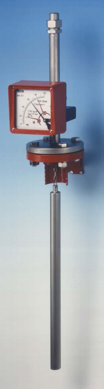
4 Introduction These Installation and Operating Instructions serve as a tool for the correct installation, operation and maintenance of the device. They are a supplement to the BA Device Description. Read the manual carefully before the device is installed and put into use. It does not include special versions or applications. All devices are thoroughly checked for order compliance and operability before delivery. Upon receipt, please conduct a visual inspection of possible damage that may be identified as having occurred during shipment. If you discover any defect, please contact our head office in Cologne or the local sales office responsible for your area (see the telephone directory at the end of this manual or on our Web site). Apart from a description of the error, we will need the equipment type and serial number of the delivery. Heinrichs Messtechnik shall not furnish guarantee for any repair work done without prior notice. Unless otherwise agreed on, the rejected parts must be made available to us in case a claim is made. consists of a scale with a pointer for displaying the liquid level. As an option, the indicator unit may be equipped with electrical transmitters for remote display or with limit transducers. If the device cannot be installed from above, because, for example, a stirrer is mounted in the container, a special displacement vessel is available for lateral installation. Since the buoyancy of the displacer rod depends on the density of the measured medium, it must have been designed for the specific liquid to be measured. The difference in density between the tank atmosphere and the liquid to be measured should be at least 100 g/l. The pressure and the temperature of the atmosphere must be known. 3.1 Level measurement in the container 1 Identification 1.1 Supplier/manufacturer Heinrichs Messtechnik GmbH Robert-Perthel-Str. 9 D Köln Phone +49 (221) Fax +49 (221) Internet: mailto:info@heinrichs-mt.com 1.2 Product type Level meter based on Archimedes principle with magnetic measured-value transmission and local level display. 1.3 Product name BA 1.4 Issue date 09/03/ Version no. 6.0 File: BA_BA_06_eng 1 = Displacer rod L = Length of displacer rod 3.2 Level measurement in the displacement vessel 2 Applications The BA-type level indicator is suitable for level measurement of liquid products in open containers and in containers under pressure. The device is based on Archimedes principle. The length of the displacer rod corresponds to the measuring range. 3 Operational mode and system design The displacer rod, which is attached to a measuring spring using a chain, immerses into the liquid and is subject to a buoyant force proportional to the mass of the displaced liquid. Every change in the weight of the rod corresponds to a change in the length of the spring and is therefore a measure of the liquid level. The longitudinal expansion of the spring, i.e. the travel of the rod, will be transmitted from the measuring space to the indicator unit by means of a magnetic coupling. The basic version of the indicator unit Page 4 of 24
5 4 Input 4.1 Measured variable Level or separation layer measurement of liquids within a density range of 400 g/l to 2000 g/l 4.2 Measuring range (lower-range and upper-range value) Level: Separation layer indicator: 5 Output 0 100% (0 XXX cm) e.g g/l The indicator unit contains a scale with a 90 reading angle. Various electrical contact makers or transmitters may be installed in the indicator unit. 5.1 Binary output Using the segments of the slot-type initiators or the eccentric discs of the microswitches, any switching point between 10% and 90% of the level can be set KEI 1 or KEI 2 limit transducers 1 or 2 limit transducers, type SJ 3,5N, make Pepperl+Fuchs (special switch possible, e.g. SN version) Safety class: PTB Nr. 99 ATEX 2219 X PTB Nr. 00 ATEX 2048 X KEM 1 or KEM 2 limit transducers (special version) Double-throw microswitches whose switching point is activated by a cam plate. KEM 1 = 1 Double-throw microswitch KEM 2 = 2 Double-throw microswitches Maximum make-break capacity: 230 VAC 50/60Hz 6 A 24 VDC 0.5 A 110 VDC 0.2 A 5.2 Analog output with the ES magneto-electric transmitter The magneto-electric transmitter is factory-calibrated to the scale values upon shipment. The signal output is supplied exclusively in a two-wire connection at 4-20 ma. Normally, the 4-20 ma signal has the HART protocol; alternatively it can have PROFIBUS PA. Additional options: 2 limit values, alternatively 1 limit value and 1 pulse output The signal output and the limit values can be configured using a HART modem operating on the following configuration programs: SensorPort from Bopp & Reuther, PDM from Siemens or AMS from Rosemount. Furthermore, a HART hand-held terminal (with DD software) can also be used. For more information about configuration, please refer to the separate Operating Instructions for the ES. The ES transmitter is available in the PROFIBUS PA version under the ES-PPA type designation. For operation details, see the separate ES-PPA Operating Instructions. Safety class: DMT 00 ATEX 075 / II2G EEx ia IIC T6 5.3 Analog output with the KINAX 3W2 angle-of-rotation transmitter The signal output of the angle-of-rotation transmitter is factory-calibrated to the scale values. The signal output is 4-20 ma in 2-wire connection; or alternatively 0-20 ma in 4- or 3-wire connection. The signal output of 4 ma corresponds to the level scale value of 0 (0 ma for the 0-20 ma version). 5.6 ma corresponds to 10% of the level scale value (2 ma). 20 ma corresponds to 100% of the level scale value. Safety class: The angle-of-rotation transmitter is a component approved for hazardous areas. When used in hazardous areas, all the values and instructions indicated in the certificate of approval must be observed. Auxiliary power is fed through an approved intrinsically safe circuit of V. To prove intrinsic safety, only authorized electrical equipment may be interconnected. Please take note of the maximum permissible ambient temperature of 60 C/75 C for the transmitter and the process temperature. Safety class: PTB 97 ATEX 2271 / II 2G EEx ia IIC T6 When installing electrical equipment in hazardous areas, the conditions and provisions specified in the approval documents must be followed. 6 Characteristic values 6.1 Accuracy Measured error +/- 5 mm from the actual value Repeatability +/- 2 mm from the actual value 6.2 Influence of ambient temperature 1. Without electrical equipment and with limit transducer without influence 2. With KINAX transmitter: +/- 0.5 % / 10 K 3. With ES transmitter: +/- 0.2 % / 10 K 6.3 Influence of fluid temperature Deviations in fluid temperature from the temperature observed during calibration can result in a proportional display fault because of the corresponding change in density. 7 Conditions of use 7.1 Mounting requirements The mounting location must be suitable for vertical installation from above. The connection size of the meter and that of the flange of the container or the displacement vessel must be identical. The pressure stages of the flanges must coincide. The surface roughness of the flange sealing surface must be suitable for the prescribed gaskets. The gaskets must be suitable for the pressure, the temperature and the corrosion of measured medium. If the container is empty, the distance between the displacer rod and the container bottom should be 20 mm. If the device is used as a separation layer indicator, the arrangement should be such that the displacer rod will be immersed into the liquid at any time. The limit values for Page 5 of 24
6 temperature and air humidity at the mounting location must be maintained and corrosive atmospheres must be avoided. In order to avoid a negative impact on magnetic measurevalue transmission, make sure that there is adequate clearance from parts that might cause magnetic interferences such as solenoid valves and ferromagnetic components such as steel brackets/supports. The minimum lateral clearance for interfering steel parts should be 200 mm. Select the mounting location so as to enable a reliable reading of the scale values. Please take note of the space requirements for any possible disassembly of the device as well. The length of the displacer rod must also be considered. The device should not be installed close to filling tubes and stirrers Device settings The measuring equipment is delivered ready for operation according to your order specifications. The limit transducers are set to the desired values. If you have submitted no requirements, the basic setting for 1 contact device: - Minimum contact switching point at 10% of falling level (damped/closed-circuit principle). 2 contact devices: Minimum contact switching point at 10% of descending level and maximum contact switching point at 90% of rising level Adjusting the limit transducers KEI The contacts are adjustable through the contact position indicators located on the scale. Dismantle the indicator cover, unfasten the contact position indicators, set to the desired value and reattach them. The following tables show the interdependencies between the temperature class, the admissible ambient temperature (Ta) and the admissible fluid temperature (Tm). Standard version Temperature class Ta Tm T6-40 C to 64 C -40 C to 80 C T5-40 C to 62 C -40 C to 95 C T4...T1-40 C to 60 C -40 C to 110 C Indicator unit raised 100 mm Temperature class Ta Tm T3-40 C to 60 C -40 C to 150 C Indicator unit raised 100 mm and pulled forward 100 mm Temperature class Ta Tm T2-40 C to 60 C -40 C to 250 C Marking for the device when the SJ 3,5...N... limit transducer is built in PTB 99 ATEX 2219 X II 2G EEx ia IIC T6-T Marking for the device when the ES magneto-electric transmitter is built in DMT 00 ATEX 075 II2G EEx ia IIC T Marking for the device when the KINAX 3W2 angle-of-rotation transmitter is built in PTB 97 ATEX 2271 II 2G EEx ia IIC T KEM The switching point can only be changed by adjusting the cam plate Use in hazardous areas Without electrical equipment The basic version of the flowmeter is a non-electrical device without its own ignition sources and meets DIN EN requirements. It can be used in hazardous areas that require Category 2 equipment. Marking: II 2GD c Tech. File Ref X Since the device does not have its own power sources that would result in a temperature increase, the fluid temperature is decisive for the maximum surface temperature. When used in potentially explosive dust atmospheres, the device must be cleaned regularly in order to avoid deposits exceeding 5 mm With built-in electrical limit transducers When the limit transducers are installed, the device becomes an electrical assembly and receives a marking in accordance with DIN EN from the entire device with the built-in electrical limit transducers. It can be used in hazardous areas that require Category 2 equipment. The electrical and thermal data and the special conditions of the EC Type Examination Certificate of the built-in limit transducers must be observed. Page 6 of 24
7 Operation in Zone 0 hazardous areas The float and its guiding system may be installed in areas that require Category 1 equipment (Zone 0). Only devices that are marked accordingly on the type plate may be operated in these areas. The conditions of use stated in the TÜV 02 ATEX 1926 X EC Type Examination Certificate must be observed. In addition, the conditions and requirements of the EC Type Examination Certificate for the respective builtin components such as ES, KINAX or limit transducers must be followed. Marking: TÜV 02 ATEX 1926 X II 1/2 G EEx ia IIC T6 T Assembly on a tank When the device is mounted on a tank, the displacer rod must be protected against inadmissible mechanical strength influence, which may result during filling or emptying events or using an agitator. The displacer rod has to be protected by a splash proof tube. 7.2 Ambient conditions 7.4 Fluid temperature limit The maximum permissible fluid temperature is stated on the type plate. The indicator unit must not be enclosed in a thermal covering. It should project from that covering at least 100 mm Installation on a container Version Standard fitting and standard indicator unit Raised 100 mm and standard indicator unit Raised 100 mm and indicator unit pulled forward 100 mm Fluid temperature -40 C to 100 C -40 C to 150 C -40 C to 250 C Installation on a displacement vessel Version Standard fitting and standard indicator unit Standard fitting and standard indicator unit pulled forward 100 mm Fluid temperature -40 C to 150 C -40 C to 250 C Ambient temperature ranges Without electrical accessories: -40 C to +80 C With limit transducer: -40 C to +65 C With KINAX signal output: -40 C to +60 C With ES signal output: -40 C to +70 C For the hazardous area version, take note of the maximum ambient temperatures depending on the temperature class as specified in the Type Examination Certificate Storage temperature The storage temperatures are identical to the ambient temperature ranges Climatic category Weather-protected and/or unheated locations, class C according to IEC 654 Part Degree of protection IP Shock resistance/vibration resistance The meter should be protected from extreme shocks and vibrations, which could cause damage Electromagnetic compatibility EN :1999 Immunity industrial environment EN Emitted interference residential environment EN 55011:1998+A1:1999 Group 1, Class B NAMUR recommendation NE Fluid conditions The fluid surface should be as calm as possible. The fluid should not bond and tend to settle. In the case of an aggressive evaporation of the fluid, the durability of the material should be clarified. In addition, the fluid should be free of turbulence that may influence the displacer. Page 7 of 24
8 8 Construction details 8.1 Type of construction/dimensions Aluminum indicator housing Page 8 of 24
9 8.1.2 Indicator housing made of stainless steel Seite 9 von 24
10 8.2 Weight Part Weight [kg] Indicator unit with ES 2 Standard fitting 5.5 Fitting raised 100 mm 6.5 Displacer rod for level measurement 3 Displacer rod for separation layer measurement Electrical connection Wiring To connect the auxiliary power, remove the indicator cover, insert the connector cable into the cable gland and attach it to the terminals according to terminal diagram. Tighten the cable gland securely, remount the indicator cover and close it tightly. 9.1 Wiring diagram for ES transmitter Seite 10 von 24
11 9.2 Wiring diagram for ES transmitter with 4-20 ma output and 2 limit transducers 9.3 Wiring diagram for inductive limit transducers Seite 11 von 24
12 9.4 Wiring diagram for KINAX 3W2 transmitter with 4-20 ma output, 2 wires 9.5 Wiring diagram for KINAX 3W2 transmitter with 4-20 ma output, 3 wires Seite 12 von 24
13 9.6 Wiring diagram for KINAX 3W2 transmitter with 4-20 ma output, 4 wires 9.7 Wiring diagram for KEM 1 and KEM 2 double-throw microswitches Seite 13 von 24
14 10 Indicator unit - Analog indicator approx. 90 with pointer - Customized product scale - ES transmitter with freely programmable user interface - Parameters may be changed based on the ES Operating Instructions. 11 Auxiliary power see Electrical connection 12 CE mark The measuring system meets the statutory requirements of the following EU directives: Directive 94/9/EC (Equipment and Protective Systems for Use in Potentially Explosive Atmospheres), the Electromagnetic Compatibility (EMC) Directive 89/336/EEC and the Pressure Equipment Directive 97/23/EC. Heinrichs Messtechnik confirms compliance with the directives by attaching the CE mark. 13 Order information Please include the following information in your order: With or without displacement vessel Connection size Pressure stage Flange sealing strip Material Installation from above: distance from the sealing strip of the flange to the bottom of the container Lateral installation: flange distance to displacement vessel Length of chain (standard version: 150 mm) Medium Density Operating temperature Operating pressure Indicator unit: standard version in cm (special scale available) Additional equipment: Signal output 4-20 ma with HART with or without limit transducer Limit transducer: 1 or 2 switching points Heating jacket with connection... High-temperature version: raised indicator unit High-temperature version: lateral indicator unit Special indicator unit made of stainless steel Drain, vent, plug, flange, valve (only for displacement vessel) Separation layer version Certificates 14 Standards and directives, certificates and approvals - Certified to DIN-EN Production in accordance with AD guidelines and HPO approval (TRB200/TRD201) - TÜV approval for welding requirements in accordance with DIN-EN Measuring range rated and converted to other products according to VDE/VDI guidelines Directive 94/9/Ec (Equipment and Protective Systems for Use in Potentially Explosive Atmospheres) - EN 50014:1997+A1-A2 - General requirements - EN 50020: Intrinsic safety i - Directive 89/336/EEC (EMC Directive) - EN :1999 Immunity industrial environment - EN Emitted interference residential environment - EN 55011:1998+A1:1999 Group 1, Class B - NAMUR recommendation NE 21 - EN Degrees of protection through housing (IP code) - EN Safety requirements for electrical measuring, control and laboratory devices - EN :2000 Switchgear and controlgear - Directive 97/23/EC (Pressure Equipment Directive) 15 Safety instructions 15.1 Intended use The BA level meter may be used only for measurements of fluid media. The manufacturer shall not be liable for damages that result from unintended or inappropriate use. When dealing with an aggressive medium, clarify the material durability of all wetted parts. When using the device in hazardous areas, follow the EC Type Examination Certificate and the applicable national installation rules Installation, start-up and operating personnel Only trained specialists authorized by the system operator may carry out the installation, electrical installations, start-up, maintenance and operation. They must read and understand the operating manual and follow its instructions. The required mounting, electrical installation, start-up and maintenance work may only be carried out by expert and authorized persons designated by the plant operator. Basically, follow the conditions and provisions applicable in your country. 16 Packaging, mounting and shipment Carefully unpack the device to avoid damaging it. Storage and installation must be done in a clean and dry room so that contamination especially of the interior of the fitting is avoided. Follow the limit values for ambient temperature. Carefully hang the displacer rod in its support. When transporting the device to a remote mounting location, we recommend that you reuse the factory-issued packaging and the transport protection. Seite 14 von 24
15 17 Maintenance The device requires no maintenance if used according to its intended purpose. However, if cleaning is necessary to remove dirt from the measuring ring or the float, take note of the following aspects: - Please take note that, with devices with built-in electrical equipment, removing the indicator cover restricts the EMC protection. - Before removing a device, make sure that the pipeline is free from the product, is depressurized and has cooled down. - Dirty displacer rods may be carefully cleaned after removal with a brush and the appropriate cleansing agent. Please make sure that the passage to the device head is free of sediments. - The switching points of the limit transducers are adjustable. To do this, remove the indicator cover, unfasten the contact point indicator located on the scale and readjust it. After the adjustment, reattach the bolts of the contact point indicator. Reinstall and tighten the indicator cover. - The calibration of the KINAX signal output is firmly set and not adjustable. Do not adjust the potentiometer of the transmitter. - The parameterization of the ES is possible and is done via HART. Please refer to the separate Operating Instructions for the ES. - The gas and viscous damping cylinders can be checked for dirt (see Installing/removing the damping sets). 19 Returning devices for repair and service Note: In accordance with the applicable German waste disposal legislation, the owner/client is responsible for the displosal of special waste and hazardous materials. Consequently, all devices sent to us for repair must be free of any hazardous materials. This also applies to possible hollow spaces and fissures in the devices. If repair is necessary, confirm the above-mentioned item in writing (please use the form in the Appendix). If hazardous materials remain in or on the device after it has been returned, Heinrichs Messtechnik shall be authorized to remove them at the client s expense without further inquiry. 20 Replacement parts The following parts can be ordered as replacement parts: 1 ) Indicator cover with window/gasket/screws 2 ) Scale with standard scaling 3 ) Pointer 4 ) Magnetic transmission sleeve with pointer axis 5 ) Float/displacer rod 6 ) Limit transducer 7 ) ES transmitter 18 Trouble shooting - Indicator window clouds over: Water in the indicator unit. - Indicator cover is not tight enough: Adjust the cover seal, tighten the cover. - Window is opaque: Corrosive atmosphere, ventilate. - Window ices over due to cold and damp atmosphere: The device can be equipped at the factory with an air/nitrogen flush. - Window ices over due to very cold medium and damp atmosphere: The device can be equipped at the factory with a pulled-forward indicator unit. - Device shows incorrect values: Compare the process data density and temperature with the values on the scale. - Pointer does not react in spite of varying level: The pointer may have gotten stuck; remove the cover and move the pointer; if the pointer can be moved easily, the displacer rod cannot move. If the pointer is unable to move further, send the device to the head office for servicing. - The displacer rod is stuck at one place due to dirt: Disassemble the device. If necessary, dismantle and clean the displacer rod. - Scale pointer pulsates: Turbulence in the fluid or agitated fluid surface. The problem can be solved by installing a splash proof tube for the displacer rod. - Electrical equipment are not functioning: Check the auxiliary power. Are suitable power supply equipment connected, have the terminals been selected correctly, has the parameterization carried out correctly? Seite 15 von 24
16 21 Exploded views 21.1 Aluminum indicator unit Name Part no. Mounting plate with 1 thread M 20 x Mounting plate with 2 threads M 20 x Bearing unit 20 Fixing screws for bearing unit 30 Dummy plug M 20 x Cable gland 41 Cable gland 42 Scale, blank 50 Scale, product scale according to original shipment (order no. necessary) 51 Screw for fixing the scale 60 Zero-point screw with nut 70 Indicator cover with glass window, gasket, screws 80 Scale pointer with hub 90 Scale pointer with hub and 2 switching dials 91 Scale pointer with hub and linearization disc 92 Scale pointer with hub and linearization disc/switching dial 93 Scale pointer with hub and 2 switching dials and ES position magnet SJ 3,5 N limit transducer with limit value indicator SJ 3,5 SN limit transducer with limit value indicator SJ 3,5 N limit transducer with limit value indicator SJ 3,5 SN limit transducer with limit value indicator 121 Connection plate for 1 limit transducer with mounting parts 130 Connection plate for 2 limit transducers with mounting parts 131 Installation set for transmitter type KINAX 3W2 Ex with lever arm and mounting parts 132 Installation set transmitter type KINAX 3W2 Ex with lever arm and mounting parts and connection for a limit 133 transducer Installation set transmitter ES Ex Hart 140 Installation set transmitter ES Ex with switch (min-max) 141 Installation set transmitter ES Ex with Profibus Complete indicator unit, local with scale Figure Complete indicator unit with 1 SJ 3,5 N limit transducer Figure 2 10 Seite 16 von 24
17 Complete indicator unit with 2 SJ 3,5 N limit transducers Complete indicator unit with E2 KINAX Ex transmitter and 1 SJ 3,5 N limit transducer Figure 3 Figure Complete indicator unit with E2 KINAX Ex transmitter Indicator unit with transmitter type ES Ex HART (141) (142) Figure 6 42 Figure Seite 17 von 24
18 22 Decontamination certificate for device cleaning Company:... City:... Department:... Name:... Tel. No.:... This level meter type BA-... was operated using the measured medium... Since this measured medium is dangerous in water/poisonous/corrosive/flammable, we have - checked that all hollow spaces of the device are free of these materials* - neutralized and flushed all hollow spaces of the device* *cross out what is not applicable. We hereby confirm that in resending the device no danger to persons or the environment is posed by the residual measured substance. Date:... Signature:... Stamp Seite 18 von 24
19 23 EC Type Examination Certificate Seite 19 von 24
20 Seite 20 von 24
21 Seite 21 von 24
22 Seite 22 von 24
23 Seite 23 von 24
24 Montage- und Betriebsanleitung BGN 24 Sales representatives Internet: 25 Notes Seite 24 von 24
Level Measurement based on Archimedes Principle. Device Description
 Level Measurement based on Archimedes Principle BA Device Description Contents 1 IDENTIFICATION...4 1.1 Supplier/manufacturer...4 1.2 Product type...4 1.3 Product name...4 1.4 Issue date...4 1.5 Version
Variable-Area Flowmeter BGN. Device Description
 Variable-Area Flowmeter BGN Device Description Contents 1 IDENTIFICATION... 4 1.1 Supplier/manufacturer... 4 1.2 Product type... 4 1.3 Product name... 4 1.4 Issue date... 4 1.5 Version no... 4 2 APPLICATIONS...
Variable-Area Flowmeter for Horizontal and Vertical Installation BGF. Device Description
 Variable-Area Flowmeter for Horizontal and Vertical Installation BGF Device Description Contents 1 Identification...4 1.1 Supplier/manufacturer...4 1.2 Product type...4 1.3 Product name...4 1.4 Issue date...4
Variable-Area Flowmeter BGN. Installation and Operating Instructions
 Variable-Area Flowmeter BGN Installation and Operating Instructions Contents 1 IDENTIFICATION... 4 1.1 Supplier/manufacturer... 4 1.2 Product type... 4 1.3 Product name... 4 1.4 Issue date... 4 1.5 Version
Operating Instructions for Full Metal Variable Area Flow Meter and Counter. Model: BGN
 Operating Instructions for Full Metal Variable Area Flow Meter and Counter Model: BGN Contents 1 IDENTIFICATION... 4 1.1 Supplier/manufacturer... 4 1.2 Product type... 4 1.3 Product name... 4 2 APPLICATIONS...
BGN. All Metal Variable Area Flow Meter. Technical Data Sheet
 All Metal Variable Area Flow Meter BGN Technical Data Sheet Extremely robust through star guiding system instead of guiding rod Flow metering of liquids, gases and steam Available up to nominal size of
Variable-Area Flow Meter for Horizontal and Vertical Installation BGF. Installation and Operating Instructions
 Variable-Area Flow Meter for Horizontal and Vertical Installation BGF Installation and Operating Instructions Contents 1 Introduction... 4 2 Identification... 4 2.1 Supplier/manufacturer... 4 2.2 Product
SITRANS P measuring instruments for pressure
 Overview Application The pressure transmitter is designed for the special requirements of the food, pharmaceutical and biotechnology industries. The use of high-grade materials guarantees compliance with
Design and application
 Design and application The function of the SGM is based on the variable area float principle. In all cases where a dependable device is required for indicating instantaneous values and monitoring the flow
Rotameter flowrate metering equipment F VA 250
 Assembly and mode of operation The operates according to the principle of flotation, as do other devices within this range: The flowing measuring substance raises the conical rotameter in the measuring
Magnetic-inductive flow meter for hazardous areas
 Magnetic-inductive flow meter for hazardous areas Technical Datasheet EPX / UMF3 high accuracy: 0.3 % of actual maintenance-free no pressure drop numerous lining materials numerous electrode materials
INLINE Flow sensor for hazardous area II 1 G/D - II 2 D - II 3 GD - I M1
 INLINE Flow sensor for hazardous area II G/D - II D - II GD - I M Type SE0 Ex can be combined with... Flow meter with NAMUR or NPN/PNP output signal Mounting, dismounting of electronics by a Quarter-Turn
Pressure transmitter JUMO dtrans p02
 JUMO GmbH & Co. KG Delivery address:mackenrodtstraße 14, 609 Fulda, Germany Postal address: 605 Fulda, Germany Phone: +49 661 600-0 Fax: +49 661 600-607 e-mail: mail@jumo.net Internet: www.jumo.net JUMO
Type 3761 Pneumatic or Electropneumatic Positioner for Rotary Actuators. Fig. 1 Type 3761 Positioner. Mounting and Operating Instructions EB 8386 EN
 Type 3761 Pneumatic or Electropneumatic Positioner for Rotary Actuators Fig. 1 Type 3761 Positioner Mounting and Operating Instructions EB 8386 EN Edition July 2007 Contents Contents Page 1 Design and
Operating Instructions
 Operating Instructions Terminal Box > 8150/1 > 8150/2 Contents 1 Contents 1 Contents...2 2 General Information...2 2.1 Manufacturer...2 2.2 Operating Instructions Information...2 3 Intended Use...2 4 Safety
Application The DA03 serves as indicator of differential. Follow mounting instructions in accordance to application.
 DA03 Differential Pressure Gauge / Differential Pressure Gauge and Switch Models for Assignment in Explosion-hazardous Areas per Directive 94/9/EC (ATEX) Application The DA03 serves as indicator of differential
Solenoid Operator 0516 / 1216
 nass magnet GmbH Edition no. 2 Eckenerstraße 4-6 2007-01-10 D-30179 Hannover Rev.2 070110 Solenoid Operator 0516 / 1216 Operating Instructions NN 8220 126 and EC Declaration of Conformity Dear Customer!
RVP-R- VAV controller. In explosion-proof version
 VAV controller In explosion-proof version RVP-R- SMAY LLC / 29 Ciep³ownicza St. / 31-587 Cracow / Poland tel. +48 12 378 18 00 / fax. +48 12 378 18 88 / e-mail: info@smay.eu Intended use VAV control units
Series 3730 Electropneumatic Positioner Type
 Series 3730 Electropneumatic Positioner Type 3730-1 Application Single-acting or double-acting positioner for attachment to pneumatic control valves. Self-calibrating, automatic adaptation to valve and
Operating Instructions for Float Flow Meter / Monitor. Model: SWK
 Operating Instructions for Float Flow Meter / Monitor Model: SWK 1. Contents 1. Contents... 2 2. Note... 3 3. Instrument Inspection... 3 4. Regulation Use... 4 5. Operating Principle... 4 6. Use in Hazardous
Volumeter TRZ 03-K PRODUCT INFORMATION. Reliable Measurements of Gas
 Volumeter TRZ 0-K PRODUCT INFORMATION Reliable Measurements of Gas Method of operation, Construction Method of operation The TRZ 0-K Volumeter is a flow meter suitable for metering gases, where the rate
Limit Switch Type 4747
 Limit Switch Type 4747 Ex d flameproof enclosure with inductive or mechanical contacts for linear actuators or rotary actuators acc. to VDI/VDE 3845 General The Type 4747 Limit Switch issues an electrical
Pneumatic or Electropneumatic Positioner for Rotary Actuators Type Fig. 1 Type 3761 Positioner. Mounting and Operating Instructions EB 8386 EN
 Pneumatic or Electropneumatic Positioner for Rotary Actuators Type 3761 Fig. 1 Type 3761 Positioner Mounting and Operating Instructions EB 8386 EN Edition June 2004 Contents Contents Page 1 Design and
KINAX SR 709 Transmitter for Position Feedback
 Position transmitter with NAMUR valve fitting Application The position feedback transmitter KINAX SR 709 (Fig. 1 and 2) is used to measure and transmit linear displacement (stroke) on various types of
RMG Meßtechnik GmbH. Publication No E
 Turbine meter TRZ 03 RMG Meßtechnik GmbH Publication No. 3.161-E P.O.Box 80 D-3550 Butzbach (Germany) Phone: +49 (0)6033 897-0 Fax: +49 (0)6033 897-130 E-mail: messtechnik@rmg.de Web site: http://www.rmg.de
Magnetic Inductive Flowmeter EP / UMF2 (B)
") Magnetic Inductive Flowmeter EP / UMF2 (B) High accuracy 0.3 % of reading No maintenance required no pressure drop different lining materials different electrode materials inexpensive earthing electrode
Magnetic Inductive Flowmeter EP / UMF2 (B) High accuracy 0.3 % of reading No maintenance required no pressure drop different lining materials different electrode materials inexpensive earthing electrode
Solenoid Operator 0513 / 1213
 nass magnet GmbH Run Nr. 5 Eckenerstraße 4-6 24.10.2006 D-30179 Hannover Rev. 5 061024 Solenoid Operator 0513 / 1213 Operating Instructions NN 8220 112 and EC Declaration of Conformity Dear Customer! In
JUMO dtrans p20. Process pressure transmitter. Type Brief description. Key features. Block diagram
 Data Sheet 403025 Page 1/10 JUMO dtrans p20 Process pressure transmitter Brief description The JUMO dtrans p20 pressure transmitter with HART interface combines maximum precision with easy operation. It
ILED Dorado. User Manual
 10NM U-code Medium Intensity Obstruction Light Helideck Status Light 15NM U-code Contents 1. Safety... 3 2. Warranty... 3 2.1 General... 3 2.2 Life span... 3 3. Type plate... 4 4. Product Description...
Installation, Operating & Maintenance Instructions. Norbro J-Switch FM 00707
 Installation, Operating & Maintenance Instructions Norbro J-Switch as FM 00707 INTRODUCTION The J-Switch is a control package incorporating switches, sensors or pneumatic valves for actuator end of travel
Instruction Manual. Ex-Time 40 / 50
 Instruction Manual Ex-Time 40 / 50 Contents 1. Introduction 13 2. Safety Advice 13 3. Faults and Damage 13-14 4. Safety Regulations 14 5. Ex-Data 14-15 6. Technical Data 15-16 7. Use and Application /
KINAX SR 709 Transmitter for position feedback
 KINAX SR 709 Transmitter f position feedback Position transmitter with NAMUR valve fitting Application The position feedback transmitter KINAX SR 709 (Fig. 1 and 2) is used to measure and transmit linear
ILED Aquarius Illuminated Windsock. User Manual
 Contents 1. Safety... 3 2. Warranty... 3 2.1 General... 3 2.2 Life span... 3 3. Type plate... 4 3.1 The light fitting has a type plate:... 4 3.2 The junction box has a type plate:... 5 4. Product Description...
Volumeter. RMG Meßtechnik GmbH. Publication No E
 Volumeter TRZ 03-K RMG Meßtechnik GmbH Publication No. 3.171-E P.O.Box 80 D-3550 Butzbach (Germany) Phone: +49 (0)6033 897-0 Fax: +49 (0)6033 897-130 E-mail: messtechnik@rmg.de Web site: http://www.rmg.de
Storage, operating and maintenance instructions for AZ plug valves and Standard valves
 ARMATUREN Plug - Valves metallic with PTFE Sleeve 2-7 way Storage, operating and maintenance instructions for AZ plug valves and Standard valves Plug - Valves FEP/PFA - lined, 2-3 way Butterfly - Valves
Measuring insert for resistance thermometer Model TR10-A
 Electrical temperature measurement Measuring insert for resistance thermometer Model TR1-A WIKA data sheet TE 6.1 for further approvals see page 6 Applications Replacement measuring insert for servicing
Flap-Type Flow Meter Prall
 Suitable for H 2 O, acids, alkaline solutions and gases Spring-loaded flap Horizontal or vertical direction of flow Largely independent of viscosity Limit contacts, optional Analog output 4 20 ma, optional
WBS 3000 Water Bottom Sensor for fuel oil and chemical storage tanks Installation and Operating Instructions
 Labkotec Oy Myllyhaantie 6 FI-33960 PIRKKALA FINLAND Tel: +358 29 006 260 Fax: +358 29 006 1260 12.3.2013 Internet: www.labkotec.com 1/12 WBS 3000 Water Bottom Sensor for fuel oil and chemical storage
Variable-Area Flowmeters KDS BGK. Operating Instructions
 Variable-Area Flowmeters KDS BGK Operating Instructions Contents 1 Introduction... 4 2 Safety instructions... 4 2.1 Installation, start-up and operating personnel... 4 2.2 Intended use... 4 2.3 Packaging,
Threaded Resistance Thermometers Model TR10-C, with Fabricated Thermowell Model TW35
 Electrical Temperature Measurement Threaded Resistance Thermometers Model TR10-C, with Fabricated Thermowell Model TW35 WIKA Data Sheet TE 60.03 Applications Machinery, plant and tank construction Energy
SATRON VDt Differential Pressure Transmitter
 SATRON VDt differential pressure transmitter belongs to V-transmitter family. The series V transmitters have both analog and smart properties. SATRON VDt is used for -,1kPa...-15 MPa ranges. It is a 2-wire
DMK 331P DMK 331P. Industrial Pressure Transmitter. Pressure Ports With Flush Welded Stainless Steel Diaphragm. Pressure Transmitter.
 TEMATEC GmbH Postal address:: Postbox 6 House address Löhestr. 7 5759 Hennef 577 Hennef Fon (+49) 0 4-87 0-0 Fax (+49) 0 4-87 0-0 http: // www.tematec.de e-mail: team@ tematec.de TEMATEC GmbH Data Sheet
Instructions Manual. Target Disk Flow meter DP-65 / DP-500. Series DP-65 DP-500. instrumentation for fluids
 instrumentation for fluids Target Disk Flow meter Series DP-65 / DP-500 Instructions Manual DP-65 DP-500 The following instruction manuals are enclosed: AMM Limit Switch Instruction manual AMD Limit Switch
DMK 331P. Industrial Pressure Transmitter. Pressure Ports With Flush Welded Stainless Steel Diaphragm
 Industrial Pressure Transmitter Pressure Ports With Flush Welded Stainless Steel Diaphragm accuracy according to IEC 60770: 0.5 % FSO Nominal pressure from 0... 60 bar up to 0... 400 bar Output signals
Ex m Solenoid Operator Type 0519
 nass magnet GmbH Eckenerstrasse 4-6 D-30179 Hannover Doc. No. 113-720-0002 Revision No. 2 01.06.2015 Ex m Solenoid Operator Type 0519 Operating Instructions Dear Customer! To ensure the function and for
DMK 331P. Industrial Pressure Transmitter. Pressure Ports With Flush Welded Stainless Steel Diaphragm. accuracy according to IEC 60770: 0.
 DMK P Industrial Pressure Transmitter Pressure Ports With Flush Welded Stainless Steel Diaphragm accuracy according to IEC 60770: 0.5 % FSO Nominal pressure from 0... 60 bar up to 0... 400 bar Output signals
INTERNATIONAL METAL ENGINEERING
 INDICATING TEMPERATURE TRANSMITTER WITH HART 8080HT UNIVERSAL SETTINGS WITH HART PROTOCOL FOR VARIOUS INPUT SIGNALS 2 WIRE TECHNOLOGY, 4 TO 20mA ANALOG OUTPUT HIGH ACCURACY IN TOTAL AMBIENT TEMPERATURE
Compact System NRGS 11-2 NRGS Original Installation Instructions English
 Compact System NRGS 11-2 NRGS 16-2 EN English Original Installation Instructions 810366-05 1 Contents Important Notes Page Usage for the intended purpose...4 Safety note...4 LV (Low Voltage) Directive
Explosion-protected surface-mounting Thermostat ATH-Ex Series
 JUMO GmbH & Co. KG Delivery address:mackenrodtstraße 14, 36039 Fulda, Germany Postal address: 36035 Fulda, Germany Phone: +49 661 6003-0 Fax: +49 661 6003-607 e-mail: mail@jumo.net Internet: www.jumo.net
Mobrey MLT100. Displacer Level Transmitter. Product Data Sheet February 2015 IP119, Rev CA. Level, contents or interface measurement transmitter
 Product Data Sheet February 2015 IP119, Rev CA Displacer Level Transmitter Level, contents or interface measurement transmitter Direct or external chamber mounting 4 20 ma HART output ATEX Intrinsically
Electronic Limit Switch Type
 Electronic Limit Switch Type 3738-20 with optional solenoid valve for on/off rotary actuators Application Electronic limit switch for on/off applications to indicate the end position of rotary actuators.
JUMO dtrans p20 DELTA
 Data Sheet 403022 Page 1/9 JUMO dtrans p20 DELTA Differential pressure transmitter Brief description The JUMO dtrans p20 DELTA differential pressure transmitter with HART interface combines maximum precision
PHOENIX CONTACT - 01/2008
 Exi Solenoid Driver, With Intrinsically Safe Output, LoopPowered, TwoChannel INTERFACE Data Sheet 0289_00_en PHOENIX CONTACT 0/2008 Description The PIEXME2SD/24/65C is a twochannel solenoid driver. It
JUMO dtrans p20. Process pressure transmitter. Brief description. Special features. Block diagram. Approvals/approval marks (see "Technical data")
") Page 1/15 JUMO dtrans p20 Process pressure transmitter Brief description The device with the HART interface combines maximum precision with simple operation. It is used to measure the system pressure of
Page 1/15 JUMO dtrans p20 Process pressure transmitter Brief description The device with the HART interface combines maximum precision with simple operation. It is used to measure the system pressure of
DMP 331 DMP 331. Industrial Pressure Transmitter for Low Pressure. Stainless Steel Sensor. Pressure Transmitter. Industrial
 TEMATEC GmbH Postal address: House address Fon (+49) 0 4-870-0 Postbox 6 Löhestr. 7 Fax (+49) 0 4-870-0 http: // www.tematec.de 5759 Hennef 577 Hennef e-mail: team@tematec.de TEMATEC GmbH Data Sheet DMP
Metal tube variable area flowmeter for gases, liquids and steam
 Metal tube variable area flowmeter for gases, liquids and steam Metallic or plastic tube with a robust construction Indication by means of magnetic coupling Scales calibrated in l/h, m 3 /h, kg/h, t/h,
Rod probe 11375Z. Technical Information. Conductive level limit detection Partially insulated rod probe for use in conductive liquids
 Technical Information Rod probe 11375Z Conductive level limit detection Partially insulated rod probe for use in conductive liquids Application Conductive level limit detection in process or storage tanks
Positioners Converters Limit Switches Position Transmitters Solenoid Valves Accessories. Selection and Application
 Positioners Converters Limit Switches Position Transmitters Solenoid Valves Accessories Selection and Application Associated s T 8355 EN ff. Edition January 2010 Information Sheet T 8350 EN Positioners,
Masoneilan Series
 Masoneilan 12300 Series Digital Level Transmitter & Controller Specification Data CU3000 02/02 Digital Level Measurement and Control Instrumentation Table of Contents General Description...2 Principle
Oriflow. Compact Orifice with HART communication. Operating instructions. A-EN RevC Latest Mod von 16
 Compact Orifice with HART communication Oriflow Operating instructions Bopp & Reuther Messtechnik GmbH Am Neuen Rheinhafen 4 67346 Speyer - Germany Phone +49 (621) 657-0 Fax +49 (621) 657-505 http://www.bopp-reuther-mt.de
XMP ci. Process Pressure Transmitter with HART -communication. Ceramic Sensor. accuracy according to IEC 60770: 0.1 % FSO.
 Process Pressure Transmitter with HART -communication Ceramic Sensor accuracy according to IEC 60770: 0.1 % FSO Nominal pressure from 0... 160 mbar up to 0... 20 bar Output signals 2-wire:... 20 ma others
Metal tube flowmeters. Series SC250. Metal Tube Flow Meters. Series SC250. Variable area flowmeter for liquids, gases and steam
 Metal tube flowmeters Variable area flowmeter for liquids, gases and steam Metallic or plastic tube with a robust construction Indication by means of magnetic coupling Scales calibrated in l/h, m 3 /h,
Resistance Thermometers Model TR217, with Spring-Loaded Probe Tip
 Electrical Temperature Measurement Resistance Thermometers Model TR217, with Spring-Loaded Probe Tip WIKA Data Sheet TE 60.22 Applications Temperature measurement at bearings of: T Pumps T Gears T Motors
Level switches (two-term level controllers) ERH-xx-04,-06,-07,-16,-16.1 Description
 ERH-xx-04,-06,-07,-16,-16.1 Description") edit. II 2015/ page 1 Level switches (two-term level controllers) ERH-xx-04,-06,-07,6,6.1 Description The limit level signalling or two-term liquid level control in the open or closed pressure tanks. The
edit. II 2015/ page 1 Level switches (two-term level controllers) ERH-xx-04,-06,-07,6,6.1 Description The limit level signalling or two-term liquid level control in the open or closed pressure tanks. The
Operating Instructions
 Operating Instructions Ex UPS Combination of > 8265/5 GUBox control panel > 8316 battery box Contents 1 Contents 1 Contents 2 2 General Information 2 3 Safety Instructions 2 4 Conformity to standards 3
Threaded resistance thermometer Model TR10-C, with fabricated thermowell model TW35
 Electrical temperature measurement Threaded resistance thermometer Model TR10-C, with fabricated thermowell model TW35 WIKA data sheet TE 60.03 for further approvals see page 7 Applications Machinery,
Operating Instructions. Angle Seat Control Valve. Type 7020
 Operating Instructions Angle Seat Control Valve Type 7020 With: Digital Positioner Type 8048 Electro-pneumatic Positioner Type 8047 Pneumatic Positioner Type 8047 Version: 02/2006 Manual-7020e.doc Art.-No:
Magnetic switch For bypass level indicators Model BGU
 Level measurement Magnetic switch For bypass level indicators BGU KSR data sheet BGU Applications Magnetic switches for detecting the limits of filling levels in bypass level indicators Chemical and petrochemical
MULTICHANNEL ULTRASONIC FLOW METER AFLOWT UF
 MULTICHANNEL ULTRASONIC FLOW METER AFLOWT UF VERSION UF-5xx d INSTALLATION MANUAL ISO 9001:2008 CONTENTS Page INTRODUCTION... 3 1. SAFETY INSTRUCTIONS... 4 2. MOUNTING PREPARATION... 4 3. MOUNTING REQUIREMENTS...
Differential pressure gauge with output signal With integrated working pressure indication (DELTA-trans) Model DPGT40
 Model DPGT40") Mechatronic pressure measurement Differential pressure gauge with output signal With integrated working pressure indication (DELTA-trans) Model DPGT40 WIKA data sheet PV 17.19 Applications weitere Zulassungen
Mechatronic pressure measurement Differential pressure gauge with output signal With integrated working pressure indication (DELTA-trans) Model DPGT40 WIKA data sheet PV 17.19 Applications weitere Zulassungen
DMP 331. Industrial Pressure Transmitter for Low Pressure. Stainless Steel Sensor
 DMP Industrial Pressure Transmitter for Low Pressure Stainless Steel Sensor accuracy according to IEC 60770: standard: 0.5 % FSO option: 0.5 / 0. % FSO Nominal pressure from 0... 00 mbar up to 0... 40
TORRIX Magnetostrictive level sensor
 TORRIX Magnetostrictive level sensor Precision Versatility Security Sensors & Systems Worldwide: www.fafnir.com FAFNIR Quality and Satisfaction Company: Based in Hamburg, Germany, FAFNIR GmbH has over
Resistance thermometer Model TR10-E, for additional thermowell
 Electrical temperature measurement Resistance thermometer Model TR10-E, for additional thermowell WIKA data sheet TE 60.05 further approvals see page 6 Applications Chemical industry Petrochemical industry
Solenoid Valves Type 3963
 Mounting and Operating Instructions Solenoid Valves Type 3963 Fig. 1 General Assembly, commissioning and operation of these devices may only be performed by experienced personnel. Proper shipping and appropriate
NAMUR FLANGE: With integrated exhaust air recirculation Ordering information
 00 TÜV-approval based on IEC 6 08, DIN V 9 Approvals: DIN EN 6/9 DVGW, group Rm and EN 6 Valves for safety systems to SIL or AK 7 / Directional control valves Actuation: electromagnetic Directly controlled
Electropneumatic Converters i/p Converters Type 6111 Mounting and Operating Instructions EB 6111 EN
 Electropneumatic Converters i/p Converters Type 6111 Fig. 1 Type 6111 in standard version Fig. Type 6111 mounted on a supply air manifold Fig. 3 Type 6111 in field enclosure Mounting and Operating Instructions
Magnetic-inductive flow meter EPS / UMF2. Technical data sheet
 Magnetic-inductive flow meter EPS / UMF2 Technical data sheet high accuracy: 0.3 % of actual maintenance-free no pressure drop numerous lining materials numerous electrode materials low-cost grounding
Electropneumatic Positioner Type Fig. 1 Type Mounting and Operating Instructions EB EN
 Electropneumatic Positioner Type 3730-2 Fig. 1 Type 3730-2 Mounting and Operating Instructions EB 8384-2 EN Firmware version 1.2x Edition December 2004 Contents Contents Page 1 Design and principle of
THE EXPERT IN LEVEL AND FLOW
 LEVEL GAUGING SYSTEM Type: Maglink Series: 5300 and 5400 Technical Information 04/2016 LEVEL THE EXPERT IN LEVEL AND FLOW Maglink Level Gauging System Technical Information Intra-Automation - 1 - Intra-Automation
Type Electronic Limit Switch
 Type 3738-20 Electronic Limit Switch With optional solenoid valve Application Electronic limit switch for on/off applications to indicate the end position. Optionally with integrated solenoid valve. Special
Reed sensor For bypass level indicators Model BLR
 Level measurement Reed sensor For bypass level indicators Model BLR WIKA data sheet LM 10.04 Applications Sensor for continuous level measurement of liquids in bypass level indicators Chemical and petrochemical
Material pressure (bar) (Cv (US) kv x 1,2 Seat. N/en
 (Cv (US) kv x 1,2 Seat. N/en") 00 / poppet valves electromagnetic actuated, directly controlled, / NPT or flanged with NAMUR Interface TÜV-approval based on IEC 6 8, DIN V Valves for safety systems up to SIL Solenoid valve also suitable
00 / poppet valves electromagnetic actuated, directly controlled, / NPT or flanged with NAMUR Interface TÜV-approval based on IEC 6 8, DIN V Valves for safety systems up to SIL Solenoid valve also suitable
Type 4746 Electric or Pneumatic Limit Switch
 Type 4746 Electric or Pneumatic Limit Switch Application Limit switches with inductive, electric or pneumatic contacts for attachment to pneumatic or electric control valves, to Type 4763 Electropneumatic
Operating Instructions Garlock Butterfly Valves DN : mm / 2-24
 Operating Instructions Garlock Butterfly Valves DN : 50-600 mm / 2-24 PN : 10 / 16 Type: GAR-SEAL SAFETY-SEAL STERILE-SEAL MOBILE-SEAL Conformity declaration... 14 0 Introduction... 15 1 Proper use...
Level instruments. Continuous level measurement - Capacitance transmitters SITRANS LC300. 5/262 Siemens FI Overview.
 Overview Configuration is an inverse frequency shift capacitance continuous It is ideal for standard industrial applications in chemical, hydrocarbon processing, food and beverage and mining, aggregate
ABB MEASUREMENT & ANALYTICS DATA SHEET. TEIP11 I/P signal converter for standard signals
 ABB MEASUREMENT & ANALYTICS DATA SHEET TEIP11 I/P signal converter for standard signals 2 TEIP11 I/P SIGNAL CONVERTER FOR STANDARD SIGNALS DS/TEIP11-EN REV. D Flow in air pressure Proven and reliable concept
Series V. Electric. switch mechanisms. and housings. Installation and Operating Manual
 Series V Installation and Operating Manual Electric switch mechanisms and housings UNPACKING Unpack the instrument carefully. Make sure all components have been removed from the foam protection. Inspect
SATRON VT Pressure Transmitter
 SATRON VT pressure transmitter belongs to the series V-transmitters. SATRON VT is used for 0-1.4 kpa...0-100 MPa ranges. It is a 2-wire transmitter with HART standard communication. In pressure measuring
ARCAPRO positioner. Positioner customized for specific tasks
 ARCAPRO ARCAPRO Positioner customized for specific tasks 2 3 1 A linear function between the input signal and stroke is the best way to ensure maximum control precision. Control valves with pneumatic actuators,
PTB 14 ATEX 2023 X, IECEx PTB X. Operating Instructions. Solenoid coil Type AC10 Magnetspule Typ AC10 Bobine magnétique Type AC10
 , IECEx PTB 14.0049X Solenoid coil Type AC10 Magnetspule Typ AC10 Bobine magnétique Type AC10 Device with II 2G/D Ex approval Geräte mit II 2G/D Ex Zulassung Appareils avec mode de protection II 2G/D Ex
Declaration of Conformity as per Directive 97/23/EC
 Declaration of Conformity as per Directive 97/23/EC The manufacturer declares that:, 47906 Kempen, Germany PTFE-lined Rotary plug valves Series 23e, with packing with lever for 90 operation with worm gear
Differential pressure transmitter PASCAL Ci4 Delta P
 Differential pressure transmitter PASCAL Ci4 Delta P for general application, Type Series CI4300 Features Differential pressure transmitter with metallic diaphragm High-resolution graphic display with
EX T... AT. Sensors with switching function. Identification II 2 G Ex db eb mb IIC PTZ 16 ATEX 0024
 ERICHR I C H O T T EX T... AT Sensors with switching function Identification II 2 G Ex db eb mb IIC T-T6 EU-type examination certificate Ambient temperature range Nominal current Temperature switch point
Nominal sizes: DN 10, 15, 20, 25, 32, 40, 50, 65, 80, 100, 125, 150 Pressure rating: PN 16. Product No. Nominal size Body connection
 Operating Instructions ERHARD Flow Indicator 1 Description of Product and Range of Application 2 Design Features Technical Data 3 Performance and Mode of Operation 4 Installation into the Pipeline Mounting
EPS 16 ATEX 1072 X, IECEx EPS X. Operating Instructions. Solenoid coil Type AC19 Magnetspule Typ AC19 Bobine magnétique Type AC19
 , IECEx EPS 16.0030X Solenoid coil Type AC19 Magnetspule Typ AC19 Bobine magnétique Type AC19 Device with II 2G/D Ex approval Geräte mit II 2G/D Ex Zulassung Appareils avec mode de protection II 2G/D Ex
-V- New. Valve series VOFC. 2009/08 Subject to change Internet:
 Valve series VOFC 2009/08 Subject to change Internet: www.festo.com/catalogue/... 159 Solenoid valves VOFC Key features General information The valves in the VOFC series are special 3/2-way and 5/2-way
System Electropneumatic Converters (Proportional Valves) Electronic Process Controllers Signal Converters
 Electronic Process Controllers Signal Converters") System 6000 Electropneumatic Converters (Proportional Valves) Electronic Process Controllers Signal Converters Edition April 2018 Information Sheet T 6000 EN Electropneumatic Converters i/p converters
System 6000 Electropneumatic Converters (Proportional Valves) Electronic Process Controllers Signal Converters Edition April 2018 Information Sheet T 6000 EN Electropneumatic Converters i/p converters
Material pressure (bar) (Cv (US) kv x 1,2 Seat
 (Cv (US) kv x 1,2 Seat") 00 / way poppet valves electromagnetic actuated, directly controlled G /, / NPT or flanged with NAMUR Interface TÜV-approval based on IEC 6 08, DIN V 9 Valves for safety systems up to SIL Solenoid valve
00 / way poppet valves electromagnetic actuated, directly controlled G /, / NPT or flanged with NAMUR Interface TÜV-approval based on IEC 6 08, DIN V 9 Valves for safety systems up to SIL Solenoid valve
JUMO dtrans p02. Pressure transmitter. General application. Approvals/marks of conformity. Data Sheet Page 1/6. II 1/2G Ex ia IIC T6 Ga/Gb
 sales@jumo.co.uk info@jumo.us Data Sheet 404385 Page 1/6 JUMO dtrans p02 Pressure transmitter II 1/2G Ex ia IIC T6 Ga/Gb General application The pressure transmitter Type JUMO dtrans p02 is used to measure
OPTISWITCH 6500 C Technical Datasheet
 OPTISWITCH 6500 C Technical Datasheet Microwave Level Switch for advanced hygienic applications Optimised sensor geometry, easy to clean Measures products with dielectric constant > 1.5 Maintenance-free