Variable-Area Flowmeter BGN. Device Description
|
|
|
- Cuthbert Osborne
- 6 years ago
- Views:
Transcription


1 Variable-Area Flowmeter BGN Device Description
2 Contents 1 IDENTIFICATION Supplier/manufacturer Product type Product name Issue date Version no APPLICATIONS OPERATIONAL MODE AND SYSTEM DESIGN Measuring principle System design INPUT Measured variable Measuring range (lower-range and upper-range value) Measuring range table OUTPUT Binary output KEI 1 or KEI 2 limit transducers KEM 1 or KEM 2 limit transducers (special version) Analog output with the ES magneto-electric transmitter Analog output with the KINAX 3W2 angle-of-rotation transmitter CHARACTERISTIC VALUES Measuring accuracy Reference conditions Measured error Repeatability Influence of ambient temperature Influence of fluid temperature CONDITIONS OF USE Mounting requirements Mounting/start-up Device settings Adjusting the limit transducer Operation in hazardous areas Ambient conditions Ambient temperature ranges Storage temperature Climatic category Degree of protection Shock resistance/vibration resistance Electromagnetic compatibility Fluid conditions Fluid temperature ranges Diagrams: Max. ambient temperature based on the fluid temperature for the ES Fluid pressure limit Inlet and outlet sections Physical state Density Viscosity Page 2 of 28
3 7.3.8 Pressure (for gas measurement) Pressure loss CONSTRUCTION DETAILS Type of construction/dimensions Aluminum indicator housing Dimension drawing for heating connection Indicator housing made of stainless steel Weight Material Process connection Magnetic filter Electrical connection Wiring diagram for ES transmitter (signal output 4-20 ma with HART ) Wiring diagram for ES transmitter with 4-20 ma output and 2 limit transducers Wiring diagram for ES transmitter with 4-20 ma output, pulse output and limit transducer Wiring diagram for inductive limit transducers Wiring diagram for KINAX 3W2 transmitter with 4-20 ma output, 2 wires Wiring diagram for KINAX 3W2 transmitter with 4-20 ma output, 3 wires Wiring diagram for KINAX 3W2 transmitter with 4-20 ma output, 4 wires Wiring diagram for KEM 1 and KEM 2 double-throw microswitches INDICATOR UNIT AUXILIARY POWER CE MARK ORDER INFORMATION Available accessories STANDARDS AND DIRECTIVES, CERTIFICATES AND APPROVALS REPLACEMENT PARTS EXPLODED VIEWS Fitting with measuring element BGN-... Standard version BGN-... with spring stop BGN-... with damping piston BGN-... with damping piston and spring stop BGN-... small measuring ranges Indicator unit Complete indicator unit, local with scale Complete indicator unit with 1 SJ 3,5 N limit transducer Complete indicator unit with 2 SJ 3,5 N limit transducers Complete indicator unit with E2 KINAX Ex transmitter Complete indicator unit with E2 KINAX Ex transmitter and 1 SJ 3,5 N limit transducer Indicator unit with transmitter type ES Ex HART EC TYPE EXAMINATION CERTIFICATE SALES REPRESENTATIVES NOTES Page 3 of 28
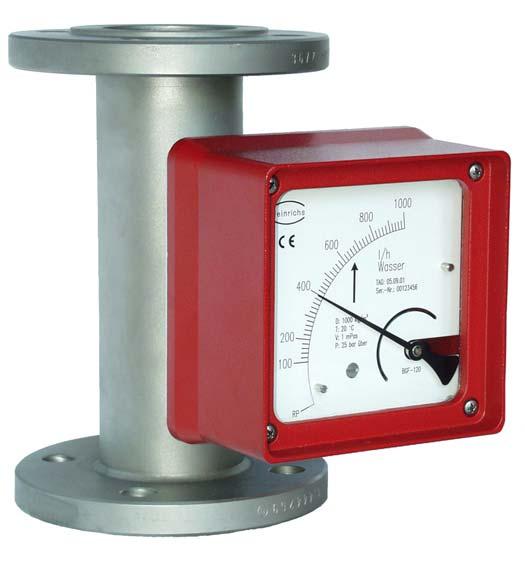
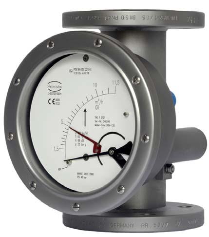
4 1 Identification 1.1 Supplier/manufacturer Heinrichs Messtechnik GmbH Robert-Perthel-Str. 9 D Köln Phone +49 (221) Fax +49 (221) Internet: mailto:info@heinrichs-mt.com 1.2 Product type Flowmeter in all-metal design based on the float principle 1.3 Product name BGN with subgroups BGN-S (stainless steel) BGN-P (PTFE) BGN-H (Hastelloy) 1.4 Issue date 08/27/ Version no. 3.0 File: BGN_GB_03_eng 2 Applications The BGN meter is suitable for flow measurement of liquid or gaseous products in pipes. It shows the current flow rate in volume or mass per unit in time. Applications: flow measurement, dosing, monitoring, adjusting and control of liquid and gaseous products. The meter s design makes it ideal for processes under difficult and adverse operating conditions. The devices are available with additional electrical equipment for process monitoring and control. 3 Operational mode and system design 3.1 Measuring principle The measuring element consists of a sharp-edged measuring ring (1) and a conical float (2). A medium flows from the bottom to the top through the measuring ring, lifting the float until the buoyancy force (A) and the weight of the float (Gs) establish equilibrium. As the height of the float varies, an annular clearance (S) proportional to the flow appears between the float and the measuring ring. The height of the float in the measuring ring is a measure of the flow. The permanent magnet (3) embedded in the float then transmits this measure to the scale and the optional electronic evaluators through a magnet tracking indicator system (4). 3.2 System design The meter consists of a cylindrical fitting pipe with flange connections on both sides. For the measuring range from 5 to 50 l/h, a measuring ring is inserted in the tube in which a conical float can move with vertical freedom. For small measuring ranges of up to 4 40 l/h, the measuring cell consists of a conical measuring tube with cylindrical float. The height of the float resulting from the flow rate is transmitted in a rotary motion by a built-in permanent magnet through a magnet tracking indicator system in a rotation to the pointer axis of the analog indicator unit. 4 Input 4.1 Measured variable Volume flow 4.2 Measuring range (lower-range and upper-range value) The lower-range value is considered 10% of the upper-range value. Measuring range span: % Smallest measuring range: l/h water Largest measuring range: l/h water (stainless steel) Page 4 of 28
5 4.3 Measuring range table Nominal size (DN) Measuring range Measuring range for water at 1000 kg/m3 Measuring range for air at bars absolute pressure Pressure loss (mbar) Remarks 15 A I/h m 3 /h 40 1)+2) B I/h m 3 /h 44 1)+2) C I/h m 3 /h 40 1)+2) D I/h m 3 /h 40 +2) E I/h m 3 /h 40 +2) F I/h m 3 /h 40 G I/h m 3 /h 40 H I/h m 3 /h 60 I I/h m 3 /h 60 J I/h m 3 /h 60 K I/h m 3 /h 70 L I/h m 3 /h 80 M I/h 3 30 m 3 /h 60 5) N I/h 4 46 m 3 /h 70 5) P I/h 7 70 m 3 /h 100 5) 25 A I/h m 3 /h 40 1)+2) B I/h m 3 /h 40 1)+2) C I/h m 3 /h 40 1)+2) D I/h m 3 /h 40 +2) E I/h m 3 /h 40 +2) F I/h m 3 /h 40 G I/h m 3 /h 40 H I/h m 3 /h 60 I I/h m 3 /h 60 J I/h m 3 /h 60 K I/h m 3 /h 70 L I/h m 3 /h 80 M I/h 3 30 m 3 /h 60 N I/h 4 46 m 3 /h 70 P I/h 7 70 m 3 /h 100 Q I/h m 3 /h 240 3)+ 4) 40 P I/h 7 70 m 3 /h 50 3) Q I/h m 3 /h 120 3) R I/h m 3 /h 180 3) 50 Q I/h m 3 /h 80 R I/h m 3 /h 90 S I/h m 3 /h 110 T I/h m 3 /h 230 U I/h m 3 /h 500 3)+ 4) 80 T I/h m 3 /h 70 U I/h m 3 /h 100 V I/h m 3 /h V I/h m 3 /h 120 W I/h m 3 /h 360 X I/h m 3 /h 600 3)+ 4) 1) for P version (PTFE), float with tantalic collar, cone of borosilicate glass measuring range: A l/h, B l/h, C l/h 2) gas throttle in S version for gas measurement included in price (pressure loss 200 mbar) 3) not available in P version 4) conversion not possible 5) only in S and H version, only with smaller sealing strip Page 5 of 28
6 5 Output Various electrical contact makers or transmitters may be installed in the indicator unit. 5.1 Binary output Using the segments of the slot-type initiators or the eccentric discs of the microswitches, any switching point between 10% and 90% of the flow rate can be set KEI 1 or KEI 2 limit transducers 1 or 2 limit transducers, type SJ 3,5N, make Pepperl+Fuchs (special switch possible, e.g. SN version) Safety class: PTB Nr. 99 ATEX 2219 X PTB Nr. 00 ATEX 2048 X KEM 1 or KEM 2 limit transducers (special version) Double-throw microswitches whose switching point is activated by a cam plate. KEM 1 = 1 Double-throw microswitch KEM 2 = 2 Double-throw microswitches Maximum make-break capacity: 230 VAC 50/60Hz 6 A 24 VDC 0.5 A 110 VDC 0.2 A 5.2 Analog output with the ES magneto-electric transmitter The magneto-electric transmitter is factory-calibrated to the scale values upon shipment. The signal output is supplied exclusively in a two-wire connection at 4-20 ma. Normally, the 4-20 ma signal has the HART protocol; alternatively it can have PROFIBUS PA. Additional options: 2 limit values, alternatively 1 limit value and 1 pulse output The signal output and the limit values can be configured using a HART modem operating on the following configuration programs: SensorPort from Bopp & Reuther, PDM from Siemens or AMS from Rosemount. Furthermore, a HART hand-held terminal (with DD software) can also be used. For more information about configuration, please refer to the separate Operating Instructions for the ES. Safety class: DMT 00 ATEX 075 / II2G EEx ia IIC T6 When installing electrical equipment in hazardous areas, the conditions and provisions specified in the approval docmuments must be followed. 5.3 Analog output with the KINAX 3W2 angle-of-rotation transmitter The signal output of the angle-of-rotation transmitter is factory-calibrated to the scale values. The signal output is 4-20 ma in 2-wire connection; or alternatively 0-20 ma in 4- or 3-wire connection. The signal output of 4 ma corresponds to the flow rate scale value of 0 (0 ma for the 0-20 ma version). 5.6 ma corresponds to 10% of the flow rate scale value (2 ma). 20 ma corresponds to 100% of the flow rate scale value. Use in hazardous areas: The angle-of-rotation transmitter is a component approved for hazardous areas. When used in hazardous areas, all the values and instructions indicated in the certificate of approval must be observed. Auxiliary power is fed through an approved intrinsically safe circuit of V. To prove intrinsic safety, only authorized electrical equipment may be interconnected. Please take note of the maximum permissible ambient temperature of 60 C/75 C for the transmitter and the process temperature. Safety class: PTB 97 ATEX 2271 / II 2G EEx ia IIC T6 6 Characteristic values 6.1 Measuring accuracy Reference conditions Water 20 C Measured error (for liquids) BGN-S/H/P +/- 1.6% of URV for local display (URV = upper-range value) (for gases) BGN-S/H/P +/- 2.0% of URV for local display Additional inaccuracy for: ES = +/- 0.2% KINAX 3W2 = +/- 0.5% Repeatability +/- 0.5 % of upper-range value 6.2 Influence of ambient temperature 1. Without electrical equipment and with limit transducer without influence 2. With KINAX transmitter: +/- 0.2 % / 10 K reference temperature 23 C 3. With ES transmitter: +/- 0.5 % / 10 K reference temperature 22 C 6.3 Influence of fluid temperature Deviations in fluid temperature from the temperature observed during calibration can result in a proportional display fault because of the corresponding change in density. Changes in viscosity cause a non-linear display fault. 7 Conditions of use The VDI/VDE guidelines 3513, Sheet 3, must be observed. The meter is suitable for : 1) Liquids with sufficient flowability that are free of solids, do not bond and do not tend to settle. 2) Gases with linear flow behavior and an adequate inlet pressure. 7.1 Mounting requirements The mounting location must be suitable for a vertical direction of flow from the bottom to the top. Important: If that is impossible, then the device type BGF may be utilized. This device can be used for both horizontal and vertical direction of flow. Page 6 of 28
7 The limit values for temperature and air humidity at the mounting location must be maintained. Avoid corrosive atmospheres. If this cannot be avoided, ventilation must be installed. Please make sure that there is adequate clearance from parts that might cause magnetic interferences such as solenoid valves and ferromagnetic components like steel brackets/supports. We recommend that the minimum lateral distance between two adjacently mounted devices be 300 mm. The devices can be mounted close together if vertically offset by one device length. The minimum lateral clearance for interfering steel parts should be 200 mm. In case of doubt, check the interference by moving the device back and forth in the selected distance by about 200 mm and testing whether the pointer position changes. Select the mounting location so as to enable a reliable reading of the scale values. Please take note as well of the space requirement for any possible disassembly of the device. As a rule, inlet and outlet sections in front of and behind the device are unnecessary if the medium has a linear flow profile. Avoid mounting accessories converging on one side in front of the device. However, if this is indispensable maintain a minimum device length of 250 mm as an inlet section. The nominal size of the pipes to be connected must correspond to that of the meter. Avoid fittings converging on one side directly in front of the device. As a rule, install valves behind the measuring equipment if there are gases involved Mounting/start-up The device must be mounted in accordance with the direction of flow from the bottom to the top (perpendicularly). Please observe the prior reference to the BGF-type device. If there is risk of dirt or solid matter penetrating the process pipes, flush them beforehand so that these materials do not get caught in the device. Ferromagnetic solid matter such as spatter can lead to the breakdown of the device. If these materials are still present during normal operating conditions, mount a magnetic filter (accessory) in front of the device. When using liquids, flush to avoid a surge of gas bubbles. Slowly increase the supply pressure when using gases to prevent pressure surges. Basically, avoid activation using solenoid valves to prevent the float from shooting upwards Gas measurement When using gases, slowly let the operating pressure rise. At the same time, vary the operating pressure through a setting valve so that the float is not knocked around since otherwise this would damage the measuring element Device settings The measuring equipment is delivered ready for operation according to your order specifications. The limit transducers are set to the desired values. If you have submitted no requirements, the basic setting for 1 contact device: - Minimum contact switching point at 10% of descending flow (damped/closed-circuit principle). 2 contact devices: Minimum contact switching point at 10% of descending flow and maximum contact switching point at 90% of ascending flow Adjusting the limit transducer The contacts are adjustable through the contact position indicators located on the scale. Dismantle the indicator cover, unfasten the contact position indicators, set to the desired value and reattach them. The nominal size of the device and that of the pipes must be the same. The pressure stages and, hence, the dimensions of the flanges must coincide. The surface roughness of the flange sealing surface must be suitable for the prescribed gaskets. Please check whether possible accessories like spring stops, gas/liquid-type dampers are still correctly sitting on the flange. Check whether the mounting clearance between the flanges of the pipes corresponds to the assembly dimension of the device plus two gaskets. To achieve stress-free mounting, the flanges of the pipes must be aligned parallel to each other. Use connecting bolts and gaskets in the prescribed dimensions. The gaskets must be suitable for the operating pressure, the temperature and the measured medium. With PTFE-coated devices, use gaskets whose interior and exterior diameter correspond to the sealing strip of the device. Tighten the screws crosswise so that the process connections are tight. See to the tightening torques of screws especially with PTFE-coated devices. The maximum torques for PTFE-coated devices are: DN15/DN25 = 14 Nm/DN50 = 25 Nm/DN80 = 35 Nm/DN100 = 42 Nm (following VDI/VDE Guideline 3513). Please check whether the pipe is adequately stable to rule out the possibility of vibration or swinging of the device. (Do not use steel mounting parts on the device.) When gas is used as the medium, pay special attention to the position of the valve. If the device is calibrated to more than bars absolute pressure, the valve is usually installed behind the flowmeter. At bars absolute pressure (free exhaust) install it in front of the device. Page 7 of 28
8 7.1.4 Operation in hazardous areas Without electrical equipment The basic version of the flowmeter is a non-electrical device without its own ignition sources and meets DIN EN requirements. It can be used in hazardous areas that require Category 2 equipment. Example for calculating the max. fluid temperature based on the max. ambient temperature for the built-in sensor Type ES for DN 15/25. T a = 70 C T amb = 60 C F = 0.2 Marking: II 2GD c Reg. Nr.: BVS 03 ATEX H/B 112 Tech. File Ref X Ta Tamb 70 C 60 C Tm = + Tamb = + 60 C = 110 C F 0,2 Since the device does not have its own power sources that would result in a temperature increase, the fluid temperature is decisive for the maximum surface temperature. When used in potentially explosive dust atmospheres, the device must be cleaned regularly in order to avoid deposits exceeding 5 mm With built-in electrical limit transducers When the limit transducers are installed, the device becomes an electrical assembly and receives a marking in accordance with DIN EN from the entire device with the built-in electrical limit transducers. The electrical and thermal data and the special conditions of the EC Type Examination Certificate of the built-in limit transducers must be observed (see also the diagram in Section 7.3.2). The influence of the fluid temperature on the built-in limit transducers must be observed. The overtemperature of the maximum fluid temperature based on the maximum ambient temperature must be considered with a factor according to the following table: Nominal size Factor for standard version DN15 and DN DN40 and DN DN80 and DN Example for built-in limit transducer for DN 15 and DN 25: Max. ambient temperature T amb = 40 C Max. fluid temperature T m = 120 C Factor for brought-in heat F = 0.2 Temperature class T4 T ü = T a = Overtemperature Ambient temperature of limit transducer Tü = Tm Tamb = 120 C 40 C = 80 C Ta = Tü * F + Tamb = 80 C *0, C = 56 C Factor for the device with the indicator pulled forward In accordance with the tables in the PTB 99 ATEX 2219 X EC Type Examination Certificate, the SJ 3,5-... N... inductive sensor must be operated in the T5 temperature class with an intrinsically safe circuit that does not exceed the maximum values of the Type 3 circuit. When using the device in hazardous areas, follow the applicable national installation rules Marking for the device when the SJ 3,5...N... limit transducer is built in PTB 99 ATEX 2219 X II 2G EEx ia IIC T6-T Marking for the device when the ES magnetoelectric transmitter is built in DMT 00 ATEX 075 II2G EEx ia IIC T Marking for the device when the KINAX 3W2 angle-of-rotation transmitter is built in PTB 97 ATEX 2271 II 2G EEx ia IIC T6 7.2 Ambient conditions Ambient temperature ranges Without electrical accessories: -40 C to +80 C With limit transducer: -40 C to +65 C With KINAX signal output: -40 C to +60 C With ES signal output: -40 C to +70 C For the hazardous area version, take note of the maximum ambient temperatures depending on the temperature class as specified in the Type Examination Certificate Storage temperature The storage temperatures are identical to the ambient temperature ranges Climatic category Weather-protected and/or unheated locations, class C Degree of protection IP Shock resistance/vibration resistance The meter should be protected from extreme shocks and vibrations, which could cause damage Electromagnetic compatibility EN :1999 Immunity industrial environment EN Emitted interference residential environment EN 55011:1998+A1:1999 Group 1, Class B NAMUR recommendation NE 21 Page 8 of 28
9 7.3 Fluid conditions Fluid temperature ranges BGN-S/H : - 40 C to +200 C Special design: -80 C to +350 C BGN-P : - 20 C to +125 C Diagrams: Max. ambient temperature based on the fluid temperature for the ES Standard version 70,0 Max. ambient temperature [ C] 60,0 50,0 40,0 30,0 20, Fluid temperature [ C] DN15/25 DN40/50 DN80/100 Indicator pulled forward 70,0 Max. ambient temperature [ C] 65,0 60,0 55, Fluid temperature [ C] DN15/25 DN40/50 DN80/100 Page 9 of 28
10 7.3.3 Fluid pressure limit Standard design BGN-S/H DN 15/25/40/50/80 PN 40; DN 100 PN 16 Special design up to PN 400 BGN-P DN 15/25/50/80/100 PN Inlet and outlet sections Inlet and outlet sections are not required for a linear flow profile of the fluid. For an extremely non-linear flow profile (e.g. shut-off/control valves are located in front of the meter), we recommend an inlet section with a mounting length of 250 mm (see also guidelines in accordance with VDI/VDE 3513) Physical state Liquid or gaseous Density Liquids: up to 2.0 kg/l Gases: no restrictions Viscosity The influence of viscosity depends on various factors. Therefore, it must be calculated for each application Pressure (for gas measurement) The measured values only apply to the calibrated fluid data stated on the scale. Any change or deviation in pressure will cause a display fault Pressure loss Depends on the meter size and the measuring range (see Measuring range table). Page 10 of 28
11 8 Construction details 8.1 Type of construction/dimensions Aluminum indicator housing Dimension drawing for heating connection Deviating mounting dimensions: (1) With preceding magnetic filter, 50 mm longer plus 2 gaskets (2) 265 mm with the indicator pulled forward (3) 175 mm with the indicator pulled forward (4) For special design DN 100: 120 mm Connections for heating jacket Pipe for Ermeto 12 mm Flange in acc. with DIN DN 15 or DN 25 PN 40 Flange in acc. with ANSI ½ 150 lbs The DN 25 flange is a special version. Dimensions: DN PN Inside diameter A Page 11 of 28
12 8.1.3 Indicator housing made of stainless steel 8.2 Weight Nominal size Weight [kg] DN 15 3 DN DN 40 6 DN DN DN Nominal size ¾, 150 lbs, ANSI B16.5 1, 150 lbs, ANSI B ½, 150 lbs, ANSI B16.5 2, 150 lbs, ANSI B16.5 3, 150 lbs, ANSI B16.5 4, 150 lbs, ANSI B16.5 Weight [kg] Nominal size ¾, 300 lbs, ANSI B16.5 1, 300 lbs, ANSI B ½, 300 lbs, ANSI B16.5 2, 300 lbs, ANSI B16.5 3, 300 lbs, ANSI B16.5 4, 300 lbs, ANSI B16.5 Weight [kg] DN PN Inside diameter A Deviating mounting dimensions: (1) 265 mm with the indicator pulled forward Page 12 of 28
13 8.3 Material Fitting Type Measuring tube Lining of Flanges Flange lining Float measuring tube BGN S Stainless steel none Stainless steel none Stainless steel BGN P Stainless steel PTFE Stainless steel PTFE PTFE BGN H DN15/25 ¾ /1 Hastelloy HC4 none Hastelloy HC4 none Hastelloy HC4 BGN H > DN40 / 1½ Hastelloy HC4 none Stainless steel Hastelloy HC4 Hastelloy HC4 Indicator Type Base plate Housing BGN S/P/H Aluminum Aluminum, safety glass window Optional Stainless steel Stainless steel, safety glass window 8.4 Process connection BGN-S/H BGN-P DN 15 PN 40 PN 16 DN 25 PN 40 PN 16 DN 40 PN 40 PN 16 DN 50 PN 40 PN 16 DN 80 PN 40 PN 16 DN 100 PN 16 PN 16 BGN S/ H BGN P ANSI ¾ B lbs 1) 300 lbs 1) 150 lbs 2) 300 lbs 2) ANSI 1 B lbs 1) 300 lbs 1) 150 lbs 2) 300 lbs 2) ANSI 1 ½ B lbs 1) 300 lbs 1) 150 lbs 2) 300 lbs 2) ANSI 2 B lbs 1) 300 lbs 1) 150 lbs 2) 300 lbs 2) ANSI 3 B lbs 1) 300 lbs 1) 150 lbs 2) 300 lbs 2) ANSI 4 B lbs 2) 300 lbs 2) 150 lbs 2) 300 lbs 2) 1) Entire device PN 40 2) Entire device PN 16 Additional equipment: special flanges, union, food connection, welding connection The S/H versions in special design are available up to PN Magnetic filter The BGN flowmeter is sensitive to impure media. Before installing the device, clean the pipes of dirt, spatter and other foreign matter. If the medium comes with solid particles, connect a suitable filter in series. When dealing with flow media with ferrous particles, we recommend the connection of a magnetic filter. To protect both magnetic filter types, MF-S (stainless steel) and MF-P/S (PTFE/stainless steel), from corrosion, encapsulated permanent magnets are laid out in spiral form. The spiral mounting produces optimum effect at small pressure loss. The filter can be supplied with groove or tongue, projection or return, other standards or special connections according to customer wishes. Dimensions: DN g (mm) Page 13 of 28
14 8.6 Electrical connection Wiring To connect the auxiliary power, remove the indicator cover, insert the connector cable into the cable gland and attach it to the terminals according to terminal diagram. Tighten the cable gland securely, remount the indicator cover and close it tightly Wiring diagram for ES transmitter (signal output 4-20 ma with HART ) Wiring diagram for ES transmitter with 4-20 ma output and 2 limit transducers Page 14 of 28
15 8.6.3 Wiring diagram for ES transmitter with 4-20 ma output, pulse output and limit transducer Wiring diagram for inductive limit transducers Page 15 of 28
16 8.6.5 Wiring diagram for KINAX 3W2 transmitter with 4-20 ma output, 2 wires Wiring diagram for KINAX 3W2 transmitter with 4-20 ma output, 3 wires Page 16 of 28
17 8.6.7 Wiring diagram for KINAX 3W2 transmitter with 4-20 ma output, 4 wires Wiring diagram for KEM 1 and KEM 2 double-throw microswitches Page 17 of 28
18 9 Indicator unit - Analog indicator approx. 90 with pointer - Customized product scale - ES transmitter with freely programmable user interface - Parameters may be changed based on the ES Operating Instructions. 10 Auxiliary power see Electrical connection 11 CE mark The measuring system meets the statutory requirements of the following EU directives: Directive 94/9/EC (Equipment and Protective Systems for Use in Potentially Explosive Atmospheres), the Electromagnetic Compatibility (EMC) Directive 89/336/EEC and the Pressure Equipment Directive 97/23/EC. Measuring sensors with a connection nominal size equal to or smaller than or DN 25 fall within the scope of application of Article 3, section 3, of the Pressure Equipment Directive and need no CE mark in accordance with this directive. Heinrichs Messtechnik confirms compliance with the directives by attaching the CE mark. 12 Order information Please include the following information in your order: Product data, specific weight, temperature, pressure, viscosity, material design, connection size, measuring range, desired accessories, required approvals and material certificates. See Device selection by model code Available accessories - Stainless steel indicator unit, glass window IP 66 - Indicator unit for high or low temperatures pulled forward by 100 mm - Fitting with heating or cooling jacket (with Ermeto or flange connection) - Float system with viscous damping - Float system with gas damping - Float system with spring stop - 1 or 2 inductive limit transducers - KINAX or ES electric transmitter - Drainable fitting (pump has been disconnected) - Magnetic filter 13 Standards and directives, certificates and approvals - Certified to DIN-EN Production in accordance with AD guidelines and HPO approval (TRB200/TRD201) - TÜV approval for welding requirements in accordance with DIN-EN Measuring range rated and converted to other products according to VDE/VDI guidelines Directive 94/9/Ec (Equipment and Protective Systems for Use in Potentially Explosive Atmospheres) - EN 50014:1997+A1-A2 - General requirements - EN 50020: Intrinsic safety i - Directive 89/336/EEC (EMC Directive) - EN :1999 Immunity industrial environment - EN Emitted interference residential environment - EN 55011:1998+A1:1999 Group 1, Class B - NAMUR recommendation NE 21 - EN Degrees of protection through housing (IP code) - EN Safety requirements for electrical measuring, control and laboratory devices - EN :2000 Switchgear and controlgear - Directive 97/23/EC (Pressure Equipment Directive) 14 Replacement parts The following parts can be ordered as replacement parts: 1 ) Indicator cover with window/gasket/screws 2 ) Scale with standard scaling 3 ) Pointer 4 ) Limit value indicator 5 ) Pointer stop 6 ) Float with guides and safety screw 7 ) Spring stop 8 ) Complete gas damping set with float 9 ) Complete viscous damping set with float 10) Screwed cone set with float for small measuring range up to 40 l/h 11 ) Limit value initiatior Page 18 of 28
19 15 Exploded views BGN-... with spring stop 15.1 Fitting with measuring element Name (Figures 12-15) Part no. BGN - Fitting 1 BGN - Fitting with Spring stop for float 2 Float 3 Float with damping piston 4 Spring stop 5 gas damping 6 gas damping with Spring stop BGN-... Standard version Figure BGN-... with damping piston Figure 12 Figure 14 Page 19 of 28
20 BGN-... with damping piston and spring stop BGN-... small measuring ranges Figure 15 Figure 16 Name (Figures 16) Part no. Fitting for small measuring range 1 gasket 2 Cone with spring stop 3 Float 4 Page 20 of 28
21 15.2 Indicator unit Name Part no. Mounting plate with 1 thread M 20 x Mounting plate with 2 threads M 20 x Bearing unit 20 Fixing screws for bearing unit 30 Dummy plug M 20 x Cable gland 41 Cable gland 42 Scale, blank 50 Scale, product scale according to original shipment (order no. necessary) 51 Screw for fixing the scale 60 Zero-point screw with nut 70 Indicator cover with glass window, gasket, screws 80 Scale pointer with hub 90 Scale pointer with hub and 2 switching dials 91 Scale pointer with hub and linearization disc 92 Scale pointer with hub and linearization disc/switching dial 93 Scale pointer with hub and 2 switching dials and ES position magnet SJ 3,5 N limit transducer with limit value indicator SJ 3,5 SN limit transducer with limit value indicator SJ 3,5 N limit transducer with limit value indicator SJ 3,5 SN limit transducer with limit value indicator 121 Connection plate for 1 limit transducer with mounting parts 130 Connection plate for 2 limit transducers with mounting parts 131 Installation set for transmitter type KINAX 3W2 Ex with lever arm and mounting parts 132 Installation set transmitter type KINAX 3W2 Ex with lever arm and mounting parts and connection for a limit 133 transducer Installation set transmitter ES Ex Hart 140 Installation set transmitter ES Ex with switch (min-max) 141 Installation set transmitter ES Ex with Profibus Complete indicator unit, local with scale Complete indicator unit with 1 SJ 3,5 N limit transducer Figure Complete indicator unit with 2 SJ 3,5 N limit transducers Figure 1 Figure Page 21 of 28
22 Complete indicator unit with E2 KINAX Ex transmitter Indicator unit with transmitter type ES Ex HART (141) (142) Figure 4 41 Figure Complete indicator unit with E2 KINAX Ex transmitter and 1 SJ 3,5 N limit transducer Figure Name Part no. Mounting plate with 1 thread M 20 x Mounting plate with 2 threads M 20 x Bearing unit 20 Fixing screws for bearing unit 30 Dummy plug M 20 x Cable gland 41 Cable gland 42 Scale, blank 50 Scale, product scale according to original shipment (order no. necessary) 51 Screw for fixing the scale 60 Zero-point screw with nut 70 Indicator cover with glass window, gasket, screws 80 Scale pointer with hub 90 Scale pointer with hub and 2 switching dials 91 Scale pointer with hub and linearization disc 92 Scale pointer with hub and linearization disc/switching dial 93 Scale pointer with hub and 2 switching dials and ES position magnet SJ 3,5 N limit transducer with limit value indicator SJ 3,5 SN limit transducer with limit value indicator SJ 3,5 N limit transducer with limit value indicator SJ 3,5 SN limit transducer with limit value indicator 121 Connection plate for 1 limit transducer with mounting parts 130 Connection plate for 2 limit transducers with mounting parts 131 Installation set for transmitter type KINAX 3W2 Ex with lever arm and mounting parts 132 Installation set transmitter type KINAX 3W2 Ex with lever arm and mounting parts and connection for a limit 133 transducer Installation set transmitter ES Ex Hart 140 Installation set transmitter ES Ex with switch (min-max) 141 Installation set transmitter ES Ex with Profibus 142 Page 22 of 28
23 16 EC Type Examination Certificate Page 23 of 28
24 Page 24 of 28
25 Page 25 of 28
26 Page 26 of 28
27 Page 27 of 28
28 17 Sales representatives Internet: 18 Notes Page 28 of 28
Variable-Area Flowmeter for Horizontal and Vertical Installation BGF. Device Description
 Variable-Area Flowmeter for Horizontal and Vertical Installation BGF Device Description Contents 1 Identification...4 1.1 Supplier/manufacturer...4 1.2 Product type...4 1.3 Product name...4 1.4 Issue date...4
Level Measurement based on Archimedes Principle. Device Description
 Level Measurement based on Archimedes Principle BA Device Description Contents 1 IDENTIFICATION...4 1.1 Supplier/manufacturer...4 1.2 Product type...4 1.3 Product name...4 1.4 Issue date...4 1.5 Version
Variable-Area Flowmeter BGN. Installation and Operating Instructions
 Variable-Area Flowmeter BGN Installation and Operating Instructions Contents 1 IDENTIFICATION... 4 1.1 Supplier/manufacturer... 4 1.2 Product type... 4 1.3 Product name... 4 1.4 Issue date... 4 1.5 Version
Operating Instructions for Full Metal Variable Area Flow Meter and Counter. Model: BGN
 Operating Instructions for Full Metal Variable Area Flow Meter and Counter Model: BGN Contents 1 IDENTIFICATION... 4 1.1 Supplier/manufacturer... 4 1.2 Product type... 4 1.3 Product name... 4 2 APPLICATIONS...
Level Measurement based on Archimedes Principle. Installation and Operating Instructions
 Level Measurement based on Archimedes Principle BA Installation and Operating Instructions Contents 1 IDENTIFICATION...4 1.1 Supplier/manufacturer...4 1.2 Product type...4 1.3 Product name...4 1.4 Issue
BGN. All Metal Variable Area Flow Meter. Technical Data Sheet
 All Metal Variable Area Flow Meter BGN Technical Data Sheet Extremely robust through star guiding system instead of guiding rod Flow metering of liquids, gases and steam Available up to nominal size of
Variable-Area Flow Meter for Horizontal and Vertical Installation BGF. Installation and Operating Instructions
 Variable-Area Flow Meter for Horizontal and Vertical Installation BGF Installation and Operating Instructions Contents 1 Introduction... 4 2 Identification... 4 2.1 Supplier/manufacturer... 4 2.2 Product
Rotameter flowrate metering equipment F VA 250
 Assembly and mode of operation The operates according to the principle of flotation, as do other devices within this range: The flowing measuring substance raises the conical rotameter in the measuring
SITRANS P measuring instruments for pressure
 Overview Application The pressure transmitter is designed for the special requirements of the food, pharmaceutical and biotechnology industries. The use of high-grade materials guarantees compliance with
Design and application
 Design and application The function of the SGM is based on the variable area float principle. In all cases where a dependable device is required for indicating instantaneous values and monitoring the flow
Volumeter TRZ 03-K PRODUCT INFORMATION. Reliable Measurements of Gas
 Volumeter TRZ 0-K PRODUCT INFORMATION Reliable Measurements of Gas Method of operation, Construction Method of operation The TRZ 0-K Volumeter is a flow meter suitable for metering gases, where the rate
Metal tube flowmeters. Series SC250. Metal Tube Flow Meters. Series SC250. Variable area flowmeter for liquids, gases and steam
 Metal tube flowmeters Variable area flowmeter for liquids, gases and steam Metallic or plastic tube with a robust construction Indication by means of magnetic coupling Scales calibrated in l/h, m 3 /h,
Metal tube variable area flowmeter for gases, liquids and steam
 Metal tube variable area flowmeter for gases, liquids and steam Metallic or plastic tube with a robust construction Indication by means of magnetic coupling Scales calibrated in l/h, m 3 /h, kg/h, t/h,
Magnetic Inductive Flowmeter EP / UMF2 (B)
") Magnetic Inductive Flowmeter EP / UMF2 (B) High accuracy 0.3 % of reading No maintenance required no pressure drop different lining materials different electrode materials inexpensive earthing electrode
Magnetic Inductive Flowmeter EP / UMF2 (B) High accuracy 0.3 % of reading No maintenance required no pressure drop different lining materials different electrode materials inexpensive earthing electrode
Glass tube flowmeters Series 6000 Variable area flowmeter for liquids and gases
 Glass tube flowmeters Series 6000 Variable area flowmeter for liquids and gases Easy installation Local indication by means of direct reading Low pressure drop Scales directly in l/h, m 3 /h, kg/h, l/min,
Magnetic-inductive flow meter for hazardous areas
 Magnetic-inductive flow meter for hazardous areas Technical Datasheet EPX / UMF3 high accuracy: 0.3 % of actual maintenance-free no pressure drop numerous lining materials numerous electrode materials
Pressure transmitter JUMO dtrans p02
 JUMO GmbH & Co. KG Delivery address:mackenrodtstraße 14, 609 Fulda, Germany Postal address: 605 Fulda, Germany Phone: +49 661 600-0 Fax: +49 661 600-607 e-mail: mail@jumo.net Internet: www.jumo.net JUMO
Magnetic-inductive flow meter EPS / UMF2. Technical data sheet
 Magnetic-inductive flow meter EPS / UMF2 Technical data sheet high accuracy: 0.3 % of actual maintenance-free no pressure drop numerous lining materials numerous electrode materials low-cost grounding
Volumeter. RMG Meßtechnik GmbH. Publication No E
 Volumeter TRZ 03-K RMG Meßtechnik GmbH Publication No. 3.171-E P.O.Box 80 D-3550 Butzbach (Germany) Phone: +49 (0)6033 897-0 Fax: +49 (0)6033 897-130 E-mail: messtechnik@rmg.de Web site: http://www.rmg.de
RMG Meßtechnik GmbH. Publication No E
 Turbine meter TRZ 03 RMG Meßtechnik GmbH Publication No. 3.161-E P.O.Box 80 D-3550 Butzbach (Germany) Phone: +49 (0)6033 897-0 Fax: +49 (0)6033 897-130 E-mail: messtechnik@rmg.de Web site: http://www.rmg.de
Variable area flowmeter H 250
 KROHNE 10/99 D 11 H250 01 E GR Variable area flowmeter Variable area flowmeters Vortex flowmeters Flow controllers Electromagnetic flowmeters Ultrasonic flowmeters Mass flowmeters Level measuring instruments
INLINE Flow sensor for hazardous area II 1 G/D - II 2 D - II 3 GD - I M1
 INLINE Flow sensor for hazardous area II G/D - II D - II GD - I M Type SE0 Ex can be combined with... Flow meter with NAMUR or NPN/PNP output signal Mounting, dismounting of electronics by a Quarter-Turn
Application The DA03 serves as indicator of differential. Follow mounting instructions in accordance to application.
 DA03 Differential Pressure Gauge / Differential Pressure Gauge and Switch Models for Assignment in Explosion-hazardous Areas per Directive 94/9/EC (ATEX) Application The DA03 serves as indicator of differential
JUMO dtrans p20. Process pressure transmitter. Type Brief description. Key features. Block diagram
 Data Sheet 403025 Page 1/10 JUMO dtrans p20 Process pressure transmitter Brief description The JUMO dtrans p20 pressure transmitter with HART interface combines maximum precision with easy operation. It
OPTIMASS 3000 Technical Datasheet
 OPTIMASS 3000 Technical Datasheet Sensor for mass flow First choice for low flow applications Certified secondary pressure containment A common footprint for all three sizes, in Hastelloy or Stainless
JUMO dtrans p20 DELTA
 Data Sheet 403022 Page 1/9 JUMO dtrans p20 DELTA Differential pressure transmitter Brief description The JUMO dtrans p20 DELTA differential pressure transmitter with HART interface combines maximum precision
K - Flow Meter with Float
 K - Flow Meter with Float Doc. no.: 18, en_cat_k, 12/2014, rev. 1 Application All-metal flow meters with float type K are used for signaling and measuring of instant flow, flowed volume of liquid and fluent
DMP 331P DMP 331P. Industrial Pressure Transmitter. Pressure Ports And Process Connections With Flush Welded Stainless Steel Diaphragm
 DMP P Industrial Pressure Transmitter Pressure Ports And Process Connections With Flush Welded Stainless Steel Diaphragm accuracy according to IEC 60770: standard: 0.5 % FSO option: 0.5 % FSO Industrial
Vortex Flowmeters VFM 3100 F-T VFM 3100 W-T
 KROHNE 10/2001 7.02313.23.00 GR/OP Vortex Flowmeters F-T W-T Variable area flowmeters Vortex flowmeters Flow controllers Electromagnetic flowmeters Ultrasonic flowmeters Mass flowmeters Level measuring
Metal tube flowmeters Series M21 Variable area flowmeter for low flows of liquids, gases and steam
 Metal tube flowmeters Series M21 Variable area flowmeter for low flows of liquids, gases and steam Metallic tube with a robust construction Indication by means of magnetic coupling Scales calibrated in
Series 3730 Electropneumatic Positioner Type
 Series 3730 Electropneumatic Positioner Type 3730-1 Application Single-acting or double-acting positioner for attachment to pneumatic control valves. Self-calibrating, automatic adaptation to valve and
V31. Variable Area Flowmeter
 Variable Area lowmeter V Housing in stainless steel Borosilicate glass Only ealing rings ervice kind construction Replace V / V / V Limit switches (Options) Chip guard Operating principle The measuring
Oriflow. Compact Orifice with HART communication. Operating instructions. A-EN RevC Latest Mod von 16
 Compact Orifice with HART communication Oriflow Operating instructions Bopp & Reuther Messtechnik GmbH Am Neuen Rheinhafen 4 67346 Speyer - Germany Phone +49 (621) 657-0 Fax +49 (621) 657-505 http://www.bopp-reuther-mt.de
DMP 331P. Industrial Pressure Transmitter. Pressure Ports And Process Connections With Flush Welded Stainless Steel Diaphragm
 DMP P Industrial Pressure Transmitter Pressure Ports And Process Connections With Flush Welded Stainless Steel accuracy according to IEC 60770: standard: 0.5 % FSO option: 0.5 % FSO from 0... 00 mbar up
Flap-Type Flow Meter Prall
 Suitable for H 2 O, acids, alkaline solutions and gases Spring-loaded flap Horizontal or vertical direction of flow Largely independent of viscosity Limit contacts, optional Analog output 4 20 ma, optional
Variable-Area Flowmeters KDS BGK. Operating Instructions
 Variable-Area Flowmeters KDS BGK Operating Instructions Contents 1 Introduction... 4 2 Safety instructions... 4 2.1 Installation, start-up and operating personnel... 4 2.2 Intended use... 4 2.3 Packaging,
DMK 331P. Industrial Pressure Transmitter. Pressure Ports With Flush Welded Stainless Steel Diaphragm
 Industrial Pressure Transmitter Pressure Ports With Flush Welded Stainless Steel Diaphragm accuracy according to IEC 60770: 0.5 % FSO Nominal pressure from 0... 60 bar up to 0... 400 bar Output signals
Electronic Limit Switch Type
 Electronic Limit Switch Type 3738-20 with optional solenoid valve for on/off rotary actuators Application Electronic limit switch for on/off applications to indicate the end position of rotary actuators.
JUMO dtrans p02. Pressure transmitter. General application. Approvals/marks of conformity. Data Sheet Page 1/6. II 1/2G Ex ia IIC T6 Ga/Gb
 sales@jumo.co.uk info@jumo.us Data Sheet 404385 Page 1/6 JUMO dtrans p02 Pressure transmitter II 1/2G Ex ia IIC T6 Ga/Gb General application The pressure transmitter Type JUMO dtrans p02 is used to measure
DMK 331P DMK 331P. Industrial Pressure Transmitter. Pressure Ports With Flush Welded Stainless Steel Diaphragm. Pressure Transmitter.
 TEMATEC GmbH Postal address:: Postbox 6 House address Löhestr. 7 5759 Hennef 577 Hennef Fon (+49) 0 4-87 0-0 Fax (+49) 0 4-87 0-0 http: // www.tematec.de e-mail: team@ tematec.de TEMATEC GmbH Data Sheet
Plastic tube variable area flowmeter for liquids and gases
 Plastic tube variable area flowmeter for liquids and gases Low cost, excellent readability and light weight Simple installation (flanged, threaded or socket ends for solvent or fusion welding connections)
GA 24 Heavy-duty variable area flowmeter
 KROHNE 10/99 D 11 GA24 01 E GR Heavy-duty variable area flowmeter Variable area flowmeters Vortex flowmeters Flow controllers Electromagnetic flowmeters Ultrasonic flowmeters Mass flowmeters Level measuring
General Specifications
 General Specifications Model RAGG Rotameter This type of Rotameter is designed for measurement of liquids and gases. The conical glass metering tube has a free rotating float. This float is mounted in
Type 3761 Pneumatic or Electropneumatic Positioner for Rotary Actuators. Fig. 1 Type 3761 Positioner. Mounting and Operating Instructions EB 8386 EN
 Type 3761 Pneumatic or Electropneumatic Positioner for Rotary Actuators Fig. 1 Type 3761 Positioner Mounting and Operating Instructions EB 8386 EN Edition July 2007 Contents Contents Page 1 Design and
KDM ARMORED FLOW METER & SWITCH
 KDM ARMORED FLOW METER & SWITCH Flow Pressure Level Temperature measurement monitoring control S2 Short Installation Length SS, PTFE or Hastelloy Wetted Parts Analog Output Available 110 F to + 390 F Temperature
Operating Instructions for Float Flow Meter / Monitor. Model: SWK
 Operating Instructions for Float Flow Meter / Monitor Model: SWK 1. Contents 1. Contents... 2 2. Note... 3 3. Instrument Inspection... 3 4. Regulation Use... 4 5. Operating Principle... 4 6. Use in Hazardous
DMP 331 DMP 331. Industrial Pressure Transmitter for Low Pressure. Stainless Steel Sensor. Pressure Transmitter. Industrial
 TEMATEC GmbH Postal address: House address Fon (+49) 0 4-870-0 Postbox 6 Löhestr. 7 Fax (+49) 0 4-870-0 http: // www.tematec.de 5759 Hennef 577 Hennef e-mail: team@tematec.de TEMATEC GmbH Data Sheet DMP
Solenoid Operator 0516 / 1216
 nass magnet GmbH Edition no. 2 Eckenerstraße 4-6 2007-01-10 D-30179 Hannover Rev.2 070110 Solenoid Operator 0516 / 1216 Operating Instructions NN 8220 126 and EC Declaration of Conformity Dear Customer!
SATRON VDt Differential Pressure Transmitter
 SATRON VDt differential pressure transmitter belongs to V-transmitter family. The series V transmitters have both analog and smart properties. SATRON VDt is used for -,1kPa...-15 MPa ranges. It is a 2-wire
XMP ci. Process Pressure Transmitter with HART -communication. Ceramic Sensor. accuracy according to IEC 60770: 0.1 % FSO.
 Process Pressure Transmitter with HART -communication Ceramic Sensor accuracy according to IEC 60770: 0.1 % FSO Nominal pressure from 0... 160 mbar up to 0... 20 bar Output signals 2-wire:... 20 ma others
Differential Pressure and Flow meters Accessories for the Media Series
 Differential Pressure and Flow meters Accessories for the Media Series 7 8 9 10 11 6 12 Media 5 Media 6 Media 05 1 5 2 4 Media 4 3 Selection and application These accessories upgrade the devices of the
Resistance Thermometers Model TR217, with Spring-Loaded Probe Tip
 Electrical Temperature Measurement Resistance Thermometers Model TR217, with Spring-Loaded Probe Tip WIKA Data Sheet TE 60.22 Applications Temperature measurement at bearings of: T Pumps T Gears T Motors
JUMO dtrans p20. Process pressure transmitter. Brief description. Special features. Block diagram. Approvals/approval marks (see "Technical data")
") Page 1/15 JUMO dtrans p20 Process pressure transmitter Brief description The device with the HART interface combines maximum precision with simple operation. It is used to measure the system pressure of
Page 1/15 JUMO dtrans p20 Process pressure transmitter Brief description The device with the HART interface combines maximum precision with simple operation. It is used to measure the system pressure of
Operating Instructions. Angle Seat Control Valve. Type 7020
 Operating Instructions Angle Seat Control Valve Type 7020 With: Digital Positioner Type 8048 Electro-pneumatic Positioner Type 8047 Pneumatic Positioner Type 8047 Version: 02/2006 Manual-7020e.doc Art.-No:
OPTIMASS 2000 Technical Datasheet
 OPTIMASS 2000 Technical Datasheet Sensor for bulk mass flow Large diameter for bulk measurement and custody transfer of liquids and gases Stainless Steel measuring tubes (NACE Compliant) Modular electronics
Limit Switch Type 4747
 Limit Switch Type 4747 Ex d flameproof enclosure with inductive or mechanical contacts for linear actuators or rotary actuators acc. to VDI/VDE 3845 General The Type 4747 Limit Switch issues an electrical
SATRON VT Pressure Transmitter
 SATRON VT pressure transmitter belongs to the series V-transmitters. SATRON VT is used for 0-1.4 kpa...0-100 MPa ranges. It is a 2-wire transmitter with HART standard communication. In pressure measuring
Ex m Solenoid Operator Type 0519
 nass magnet GmbH Eckenerstrasse 4-6 D-30179 Hannover Doc. No. 113-720-0002 Revision No. 2 01.06.2015 Ex m Solenoid Operator Type 0519 Operating Instructions Dear Customer! To ensure the function and for
Thread Mounted Resistance Thermometers Model TR201, with Fabricated Thermowell
 Electrical Temperature Measurement Thread Mounted Resistance Thermometers Model TR201, with Fabricated Thermowell WIKA Data Sheet TE 60.15 Applications T Machinery, plant and tank construction T Energy
Threaded Resistance Thermometers Model TR10-C, with Fabricated Thermowell Model TW35
 Electrical Temperature Measurement Threaded Resistance Thermometers Model TR10-C, with Fabricated Thermowell Model TW35 WIKA Data Sheet TE 60.03 Applications Machinery, plant and tank construction Energy
Flowmeter F I Gardex. Connection and installation instructions. Application. Benefits. Design and mode of operation
 The baffle plate (b) causes a back-pressure in the medium, and the balance beam (c) is deflected. This movement is transmitted via the beam to the indicator mechanism (e) using a bellows bushing (d). gear
DMK 331P. Industrial Pressure Transmitter. Pressure Ports With Flush Welded Stainless Steel Diaphragm. accuracy according to IEC 60770: 0.
 DMK P Industrial Pressure Transmitter Pressure Ports With Flush Welded Stainless Steel Diaphragm accuracy according to IEC 60770: 0.5 % FSO Nominal pressure from 0... 60 bar up to 0... 400 bar Output signals
Thermal hysteresis 0.5% max. of full scale (within compensated temperature range) 1% max. for ranges mbar mbar mbar
 1% max. for ranges mbar mbar mbar") Pressure Transmitter Type FM40466 General application Pressure transmitters are used to measure the relative (gauge) and absolute pressures in liquids or gases. The measuring device for the transmitter
Pressure Transmitter Type FM40466 General application Pressure transmitters are used to measure the relative (gauge) and absolute pressures in liquids or gases. The measuring device for the transmitter
Instructions Manual. Target Disk Flow meter DP-65 / DP-500. Series DP-65 DP-500. instrumentation for fluids
 instrumentation for fluids Target Disk Flow meter Series DP-65 / DP-500 Instructions Manual DP-65 DP-500 The following instruction manuals are enclosed: AMM Limit Switch Instruction manual AMD Limit Switch
Operating Instruction for Flowmonitor. Model: DF-WM
 Operating Instruction for Flowmonitor Model: DF-WM 1. Contents 1. Contents... 2 2. Note... 3 3. Instrument Inspection... 3 4. Regulation Use... 4 5. Operating Principle... 5 6. Mechanical Connection...
Positive displacement flowmeter for continuous flow measurement
 8070 Positive displacement flowmeter for continuous flow measurement High accuracy Medium with high viscosity Mounting and dismounting of the electronics by a quarter-turn Connection to Bürkert devices
RVP-R- VAV controller. In explosion-proof version
 VAV controller In explosion-proof version RVP-R- SMAY LLC / 29 Ciep³ownicza St. / 31-587 Cracow / Poland tel. +48 12 378 18 00 / fax. +48 12 378 18 88 / e-mail: info@smay.eu Intended use VAV control units
Operating Instructions. Pneumatic Control Valve Low Temperature. Type Series GS3
 Operating Instructions Pneumatic Control Valve Low Temperature Type 8026 Series GS3 With: Digital Positioner Type 8048 Electro-pneumatic Positioner Type 8047 Pneumatic Positioner Type 8047 Version: 03/2006
Pressure Transmitter JUMO dtrans p30 Type
 Data Sheet 40466 Page 1/6 Pressure Transmitter JUMO dtrans p0 Type 40466 General application Pressure transmitters are used to measure the relative (gauge) and absolute pressures in liquids or gases. The
Declaration of Conformity as per Directive 97/23/EC
 Declaration of Conformity as per Directive 97/23/EC The manufacturer declares that:, 47906 Kempen, Germany PTFE-lined Rotary plug valves Series 23e, with packing with lever for 90 operation with worm gear
BFS-10-O G1/4: BFS-10-O G1/2: BFS-10-O G1: Contact rating: BFS-10-O G1/4
 Flow Switches Index: B / 923-1838 BFS-10-N / BFS-10-O for monitoring liquids, with or without optical display Features set point continuously adjustable rugged, low hysteresis, any mounting position, high
KINAX SR 709 Transmitter for Position Feedback
 Position transmitter with NAMUR valve fitting Application The position feedback transmitter KINAX SR 709 (Fig. 1 and 2) is used to measure and transmit linear displacement (stroke) on various types of
7000 Series OPTIMASS Mass Flowmeters. Titanium Hastelloy Stainless Steel
 KROHNE 04/2004 7.02445.24.00 GR 7000 Series OPTIMASS Mass Flowmeters with single straight measuring tube Titanium Hastelloy Stainless Steel Status: 10/99 Status: 10/99 One tube no limits No limits with
Solenoid Valve Island Type 3965
 Solenoid Valve Island Type 365 for the control of pneumatic actuators General The Type 365 Solenoid Valve Island is a compact solution for the centralized control of pneumatic actuators in chemical and
STEEMCO-MAS Flowmeter for Steam
 STEEMCO-MAS Flowmeter for Steam Typical Applications The STEEMCO-MAS flow meters measure the mass flow of superheated steam within the process industries, including chemical, petro-chemical, pharmaceutical
Pneumatic or Electropneumatic Positioner for Rotary Actuators Type Fig. 1 Type 3761 Positioner. Mounting and Operating Instructions EB 8386 EN
 Pneumatic or Electropneumatic Positioner for Rotary Actuators Type 3761 Fig. 1 Type 3761 Positioner Mounting and Operating Instructions EB 8386 EN Edition June 2004 Contents Contents Page 1 Design and
Flow Measurement SITRANS F C
 Siemens G 2014 SITRNS C Overview The main applications of the Coriolis flowmeter can be found in all industries, such as: Chemical and pharma Detergents, bulk chemicals, pharmaceuticals, acids, alkalis
METAL VAREA-METER STRAIGHT THROUGH TYPE ROTAMETER
 TECHNICAL INFORMATION METAL VAREA-METER STRAIGHT THROUGH TYPE ROTAMETER Electronic Transmitter INTRODUCING THE METAL TUBE VAREA-METER U.S. Filter/Wallace & Tiernan Products straight through metal tube
SITRANS F C. Flow sensor MC2 4/193. Overview
 Siemens G 2011 low Measurement SITNS C Overview The main applications of the Coriolis flowmeter can be found in all industries, such as: Chemical and pharma Detergents, bulk chemicals, pharmaceuticals,
SITRANS F M flow sensors 711/A and 711/911E
 s flow sensors 711/A and 711/911E flow sensors 711/A and 711/911E Introduction Application Mode of operation, operation Mode of operation All electromagnetic flow measurements are based on Faraday s Law
Orifice plate flowmeters Series PR By-pass flowmeter for liquids, gases and steam
 Orifice plate flowmeters Series PR By-pass flowmeter for liquids, gases and steam By-pass flowmeter with orifice plate (compact system PRC and separate system PR) for big flow ranges Flow indication by
SITRANS F flowmeters SITRANS F C
 SITRNS F flowmeters Siemens G 2008 Overview is available as a standard version (DN 50 to DN 150 (2 to 6 )) and a hygienic, EHEDG certified version (DN 20 to DN 80 (¾ to 3 )). MC2 and MC2 hygienic are suitable
DMP 331. Industrial Pressure Transmitter for Low Pressure. Stainless Steel Sensor
 DMP Industrial Pressure Transmitter for Low Pressure Stainless Steel Sensor accuracy according to IEC 60770: standard: 0.5 % FSO option: 0.5 / 0. % FSO Nominal pressure from 0... 00 mbar up to 0... 40
BM 26 BASIC/ADVANCED Technical Datasheet
 BM 26 BASIC/ADVANCED Technical Datasheet Magnetic bypass Level Indicator (MLI) for generalpurpose applications Best price / performance ratio Full stainless steel construction IP 68 local indicator with
VersaFlow Vortex 100 Vortex Flow Meter Specifications
 VersaFlow Vortex 100 Vortex Flow Meter Specifications 34-VF-03-05 May 2011 The All-In-One Solution The VERSAFLOW is the only vortex flowmeter with integrated and temperature compensation in 2- wire technology.
Solenoid Operator 0513 / 1213
 nass magnet GmbH Run Nr. 5 Eckenerstraße 4-6 24.10.2006 D-30179 Hannover Rev. 5 061024 Solenoid Operator 0513 / 1213 Operating Instructions NN 8220 112 and EC Declaration of Conformity Dear Customer! In
Operating Instructions Garlock Butterfly Valves DN : mm / 2-24
 Operating Instructions Garlock Butterfly Valves DN : 50-600 mm / 2-24 PN : 10 / 16 Type: GAR-SEAL SAFETY-SEAL STERILE-SEAL MOBILE-SEAL Conformity declaration... 14 0 Introduction... 15 1 Proper use...
Solenoid Valves Type 3963
 Mounting and Operating Instructions Solenoid Valves Type 3963 Fig. 1 General Assembly, commissioning and operation of these devices may only be performed by experienced personnel. Proper shipping and appropriate
Turbine flowmeters Series TM
 Turbine flowmeters Series TM Suitable for liquids Possibility of installation in all flow directions Special design for high pressure available Excellent relationship flow range / flowmeter size Low pressure
ORIMAS Mass Flowmeter
 Typical Applications ORIMAS Mass Flowmeter The ORIMAS mass flow meters measure the mass flow of most liquids and gases within the process industries, including chemical, petro-chemical, pharmaceutical
Micro Motion F-Series Coriolis Flow and Density Meters
 Product Data Sheet PS-00603, Rev. F December 2007 Micro Motion F-Series Coriolis Flow and Density Meters Micro Motion F-Series Coriolis meters offer highly accurate mass flow, volume flow, and density
INSERTION flow sensor for continuous flow measurement
 INSERTION flow sensor for continuous flow measurement Economic integration in pipe systems without any additional piping 3-wire frequency pulse version to directly interface with PLC s (both PNP and NPN)
Oscillating piston flowmeters Series COVOL Positive displacement flowmeter for liquids
 Oscillating piston flowmeters Series COVOL Positive displacement flowmeter for liquids Suitable for all kind of liquids Viscosity up to 120000 mpa s Excellent performance with changing process conditions
SITRANS F flowmeters SITRANS F C SITRANS F C MC2 4/169. Overview
 Siemens G 2009 SITRNS flowmeters SITRNS C SITRNS C MC2 Overview SITRNS C MC2 is available as a standard version (DN 50 to DN 150 (2 to 6 )) and a hygienic, EHEDG-certified version (DN 20 to DN (¾ to 3
Ar-Mite TM Low Flow Armored Flowmeter
 Data Sheet Brooks Ar-Mite TM MT 3750C Ar-Mite TM Low Flow Armored Flowmeter Ar-Mite TM Model MT 3750 Metal Tube Flowmeter Ar-Mite TM Model MT 3750 Metal Tube Flowmeter with Transmitter or Inductive Alarm
SITRANS F flowmeters SITRANS F C MASSFLO MASS MC1. 4/146 Siemens FI Overview
 Overview MSS 2100 MC1 DN 50 to DN 150 (2 to 6 ) is suitable for accurate mass flow measurement for all kind of liquids and gases. The sensor offers superior performance in terms of flow accuracy, turn-down
Vortex Flowmeter FV4000 (TRIO-WIRL V) Swirl Flowmeter FS4000 (TRIO-WIRL S) For flow rate and volume measurement of liquids, gases and steam
 Swirl Flowmeter FS4000 (TRIO-WIRL S) For flow rate and volume measurement of liquids, gases and steam") Vortex Flowmeter FV4000 (TRIO-WIRL V) Swirl Flowmeter FS4000 (TRIO-WIRL S) For flow rate and volume measurement of liquids, gases and steam Cost savings due to high accuracy Low investment cost through
Vortex Flowmeter FV4000 (TRIO-WIRL V) Swirl Flowmeter FS4000 (TRIO-WIRL S) For flow rate and volume measurement of liquids, gases and steam Cost savings due to high accuracy Low investment cost through
ABB MEASUREMENT & ANALYTICS DATA SHEET. TEIP11 I/P signal converter for standard signals
 ABB MEASUREMENT & ANALYTICS DATA SHEET TEIP11 I/P signal converter for standard signals 2 TEIP11 I/P SIGNAL CONVERTER FOR STANDARD SIGNALS DS/TEIP11-EN REV. D Flow in air pressure Proven and reliable concept
Absolute pressure gauge with diaphragm
 Absolute pressure gauge with diaphragm and switch function,type series BF2 Features Absolute pressure gauge with diaphragm and switch function Nominal ranges 0 60 mbar abs to 0 2500 mbar abs With integrated
SATRON VVFe Pressure Transmitter
 SATRON VVFe pressure transmitter belongs to Vtransmitter family. SATRON VVFe is used for 0 4 kpa...0500 kpa ranges. It is a 2wire transmitter with HART standard communication. SATRON VVFe pressure transmitter