DewEze Clutch Pump Kit Dodge 6.7L, 2011+, AA Pump INSTALLATION INSTRUCTIONS
|
|
|
- Coleen Long
- 6 years ago
- Views:
Transcription
1
2
3
4
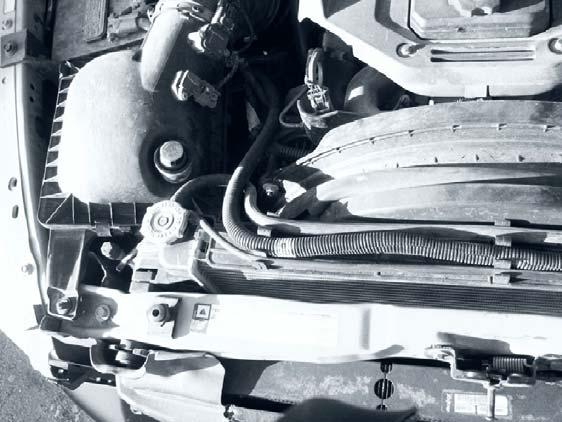
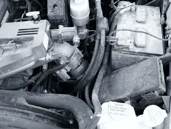
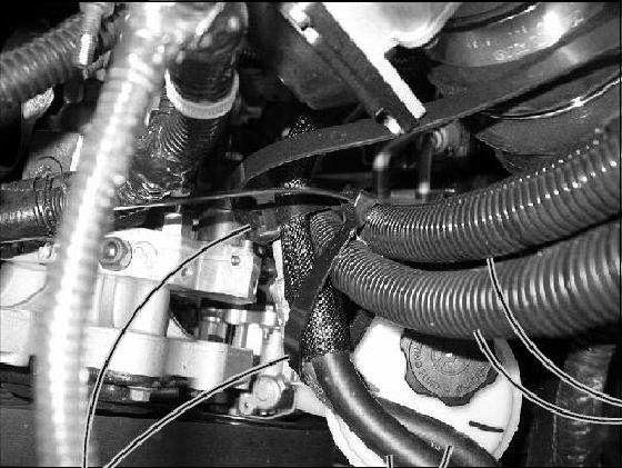
5 DewEze Clutch Pump Kit Dodge 6.7L, 2011+, AA Pump INSTALLATION INSTRUCTIONS Record Pump Model No. and Serial No. for future reference. 1. The installation of this kit requires trained decisionmaking concerning clearances, tying components together, rerouting, or relocating OEM components, etc. It is impossible to describe all of the clearance and vibration points, etc. in the installation instructions. Therefore, the technician must exercise professional judgment to achieve the best quality installation. 2. Disconnect the battery. 3. Remove the left and right fan shroud mounting nuts. Fig. 4, Disconnect wiring plug-ins from air box. Remove air box. Fig Gently bend the steel hose ends slightly if needed to keep the hoses away. 6. Remove the OEM belt. Remove the fan shroud support bracket (13). 7. Remove the OEM grooved idler pulley (15) from the front of the engine at Location C. In its place, mount the DewEze grooved idler pulley (7) with the OEM idler bushing (2) and OEM bolt (18). 8. Install DewEze belt (27) on the OEM pulleys. It is easier to access the pulleys when the shroud can be pulled away and before the pump is installed. 9. Disconnect the ground wire attached to outside of battery post clamp on right side battery and reroute on top of existing truck hoses so pump hoses will go under wire. Reconnect. Fig Hold pump (7) onto back of pump plate (5) and clutch hub (8i) onto front of bracket, making sure anti-rotation pin (P) on front of hub is on top. Place two 3/8 x 1 1/4 socket head bolts (24) and 3/8 high collar lock washers (26) through pump, through mounting plate and thread into hub. Torque to 20 lb-ft. Left and right directions are standing in front of the truck looking at the engine. 11. Slide coil (9a) over hub, aligning hole in the back plate of coil with the anti-rotation pin in the hub. The wires from the coil should be on the same side as the pin. 12. Install large snap ring (9b) to hold coil in place. NOTE: THE BEVEL ON BOTH SNAP RINGS MUST FACE AWAY FROM THE PUMP. REFER TO INSTRUCTION SHEET FOR THE CLUTCH FOR CORRECT INSTALLATION OF SNAP RINGS. 13. Slide clutch pulley (9c) onto hub. Install small snap ring (9d) to hold pulley in place. 14. Place the key onto the pump shaft. Slide the hub/armature (9f) onto the pump shaft aligning the keyways. NOTE: SET THE AIR GAP BETWEEN THE HUB/ARMATURE AND THE PULLEY USING SHIMS (9e) ACCORDING TO INSTRUCTION SHEET FOR CLUTCH. 15. Run the hoses into the engine compartment. Pull them out far enough to attach them to the pump. Attach the top of the pump bracket (1) to the engine at Location A using two M10 x 40 bolts (14). Attach the bottom of the pump bracket to the power steering bracket at Location B with the 3/8 x 2 bolt (19), and the 3/8 lock washer (17) and 3/8 nut (25) on the back. 16. Finish installing the belt (27) onto the pump pulley as shown in the diagram (Fig. 1). 17. Install air box. Install intercooler cover. Connect battery. 18. Run the engine and check for any clearance or alignment problems. Re-examine the power steering lines for clearance as the engine torques. Adjust as needed. 1
6 Installing the Warner AA clutch Hub, Coil and Rotor/Pulley are preassembled by Warner. Armature is shipped loose along with Hardware Kit (consisting of center bolt, washer and shims) Step 1: Slide the Hub/Coil/Rotor/Pulley Assembly onto the pump shaft and secure to pump face using pump manufacturer supplied bolts through the two bolt holes. Step 2: Place two shims onto pump shaft on top of rotor face. Slide armature onto shaft and measure air gap between the Armature and Rotor. Repeat this step and add shims as needed (more or less than 2) to acquire air gap between the rotor and armature. Check air gap at 3 locations apart. Step 3: Fasten center bolt and washer to face of pump shaft and tighten to 25 ft. lbs. torque. Failing to set the air gap correctly will cause premature pump failure due to axial load placed on the pump shaft.
7 Installing the Ogura AA clutch Hub, Coil and Rotor/Pulley are preassembled by Ogura. Armature is shipped loose along with Hardware Kit (consisting of center bolt, washer and shims) Step 1: Slide the Hub/Coil/Rotor/Pulley Assembly onto the pump shaft and secure to pump face using pump manufacturer supplied bolts through the two bolt holes. Step 2: Place two shims onto pump shaft on top of rotor face. Slide armature onto shaft and measure air gap between the Armature and Rotor. Repeat this step and add shims as needed (more or less than 2) to acquire 0.3 to 0.6mm (.011 to.023 ) air gap between the rotor and armature. Check air gap at 3 locations apart. Step 3: Fasten center bolt and washer to face of pump shaft and tighten to 25 ft. lbs. torque. Failing to set the air gap correctly will cause premature pump failure due to axial load placed on the pump shaft.
3. Detach the battery cable bracket (5) from the OEM alternator bracket by removing two bolts. Keep the bolts.
 from the OEM alternator bracket by removing two bolts. Keep the bolts.") DewEze Clutch Pump Kit #700370 Chevrolet/ GMC 6.0L w/ and w/o A/C AA mount 2000 INSTALLATION INSTRUCTIONS 1. Disconnect the battery. 2. Remove the OEM serpentine belt. 3. Detach the battery cable bracket
DewEze Clutch Pump Kit #700370 Chevrolet/ GMC 6.0L w/ and w/o A/C AA mount 2000 INSTALLATION INSTRUCTIONS 1. Disconnect the battery. 2. Remove the OEM serpentine belt. 3. Detach the battery cable bracket
6. Remove OEM bolts from engine at locations A, B, and C. Lay the wiring off to the side.
 700359 DewEze Clutch Pump Kit #700359 Ford 5.4L, 6.8L w/ and w/o A/C AA mount 1999- INSTALLATION INSTRUCTIONS 1. Disconnect the battery. 2. Drain the radiator. 3. Remove the air cleaner assembly. 4. Remove
DewEze I N S T A L L A T I O N I N S T R U C T I O N S. Clutch Pump Kit # Ford 6.8L Van with A/C AA mount Disconnect the battery.
 DewEze Clutch Pump Kit #700442 Ford 6.8L Van with A/C AA mount 2 0 0 6 + I N S T A L L A T I O N I N S T R U C T I O N S 1. Disconnect the battery. 2. Remove the OEM belt. Remove the fan shroud and fan.
INSTALLATION INSTRUCTIONS
 'HZ(]H INSTALLATION INSTRUCTIONS %NWVEJ2WOR-KV Ford 5.4L YCPFYQ#% ## OQWPV &KUEQPPGEVVJGDCVVGT[ &TCKPVJGTCFKCVQT 4GOQXGVJGCKTENGCPGTCUUGODN[ 4GOQXGVJGWRRGTTCFKCVQTJQUG 0QVGJQYHCTVJGHCPUVKEMUQWVDGJKPFVJGHCPUJTQWF+VYKNNDGPGEGUUCT[VQVTKOVJGUJTQWFVQ
DewEze Clutch Pump Kit
 DewEze Clutch Pump Kit 700538 Dodge 6.7L, 2011+, P415 12, 17 GPM Pump INSTALLATION INSTRUCTIONS Record Pump Model No. and Serial No. for future reference. 1. The installation of this kit requires trained
I N S T A L L A T I O N I N S T R U C T I O N S
 'HZ(]H %NWVEJ2WOR-KV &KHY\ With A/C I N S T A L L A T I O N I N S T R U C T I O N S 016'5WEVKQPJQUGVQRWOROWUVDGCYKTGDTCKFJQUGOKPKOWO+&HQTIRO RWORU+PUVCNNCVKQPUYKVJUOCNNGTUWEVKQPJQUGUYKNNXQKFVJGRWORYCTTCPV[
I N S T A L L A T I O N I N S T R U C T I O N S
 'HZ(]H %NWVEJ2WOR-KV &KHY\ 3LFNXS 9DQ With A/C I N S T A L L A T I O N I N S T R U C T I O N S 016'5WEVKQPJQUGVQRWOROWUVDGCYKTGDTCKFJQUGOKPKOWO+&HQTIRO RWORU+&HQTIRORWORU+PUVCNNCVKQPUYKVJUOCNNGTUWEVKQPJQUGU
DewEze Clutch Pump Kit Ford 6.2L Gas, A Pump, Side Port, 2011+
 DewEze Clutch Pump Kit 700512 Ford 6.2L Gas, A Pump, Side Port, 2011+ INSTALLATION INSTRUCTIONS 1. The installation of this kit requires trained decisionmaking concerning clearances, tying components together,
DewEze Clutch Pump Kit Ford 6.2L Gas, A Pump, Side Port, INSTALLATION INSTRUCTIONS 1. The installation of this kit requires trained decis
 DewEze Clutch Pump Kit 700564 Ford 6.2L Gas, A Pump, Side Port, 2014+ INSTALLATION INSTRUCTIONS 1. The installation of this kit requires trained decisionmaking concerning clearances, tying components together,
FIG. 3 BRACKET INSTALLATION. i a. e h f FIG. 4 STATOR OFFSET BRACKET REMOVE OEM SPACER. REPLACE WITH BRACKET 3.
 700510 IG. 3 BRACKET INSTALLATION E D 11 C B i a b c d e h f g A B C A IG. 4 STATOR OSET BRACKET 14 G REMOVE OEM SPACER. REPLACE WITH BRACKET 3. 9 G 8 2 4 3 DewEze Clutch Pump Kit 700510 ord 6.7L, AA Pump,
Compressor Clutch Replacement Procedure
 Clutch Replacement Procedure P-1401-WE 819-0316 Installation Instructions An Altra Industrial Motion Company Warner Replacement Clutches for the following compressors: Denso 6E171 10P15 6P148 6C17 Ford
Ford 6.8L, w/spider, 2000+
 DewEze Aiir Compressor Kiit 700554 Ford 6.8L, w/spider, 2000+ INSTALLATION INSTRUCTIONS 1. Disconnect the battery. 2. Drain the radiator. 3. Remove the air cleaner assembly. 4. Remove the upper radiator
Compressor Clutch Replacement Procedure
 P-1411 819-0361 Compressor Clutch Replacement Procedure Installation Instructions World Clutch with Unidamp Armature for Ford FX-15 and FS-10 Compressors and all Denso Models with 30mm bearing fit. Keep
BD Venom Dual Fuel F O R D 6. 7 L P O W E R S T R O K E Installation Instructions
 U 30 January 2017 (1050470) Venom Dual Fuel Kit (I-00390) 1 DOWNLOAD ENHANCED INSTALL MANUALS AT dieselperformance.com BD Venom Dual Fuel 2 0 1 1-2 0 1 4 F O R D 6. 7 L P O W E R S T R O K E Installation
INSTALLATION NOTES. 6. Add the 3/4 hose extension to the power steering reservoir to help keep the P/S hose away from the pump belt.
 YEAR:2017/ CURRENT INSTALLATION NOTES 1. Be sure to read and understand all available information including but not limited to instructions, warnings, sale terms, and warranties for the vehicle and all
BD Venom Dual Fuel F O R D 6. 7 L P O W E R S T R O K E Installation Instructions
 U 21 March 2017 (1050470) Venom Dual Fuel Kit (I-00390) 1 DOWNLOAD ENHANCED INSTALL MANUALS AT dieselperformance.com BD Venom Dual Fuel 2 0 1 1-2 0 1 6 F O R D 6. 7 L P O W E R S T R O K E Installation
Cut zip ties and remove 2 plastic wiring harness brackets.
 TROUBLESHOOTING: Please read and understand all installation instructions before proceeding with the installation. Included parts: 1 - New Bosch Cp3 Pump 1 - HSM Pulley 1 - Serpentine Belt 1 - Pump Bracket/
Compressor - Install (E.40.C.31 - F.10.A.15)
") Compressor - Install (E.40.C.31 - F.10.A.15) 1. Set the compressor on its mount and secure into place using the four bolts. Connect the refrigerant suction line (5) and the discharge line (4). Install
Compressor - Install (E.40.C.31 - F.10.A.15) 1. Set the compressor on its mount and secure into place using the four bolts. Connect the refrigerant suction line (5) and the discharge line (4). Install
AEV30243AJ Last Updated: 11/14/17. 3 Dualsport front suspension ram truck 2500/3500 INSTALLATION GUIDE
 AEV30243AJ Last Updated: 11/14/17 3 Dualsport front suspension ram truck 2500/3500 INSTALLATION GUIDE PLEASE READ BEFORE YOU START TO GUARANTEE A QUALITY INSTALLATION, WE RECOMMEND READING THESE INSTRUCTIONS
Air Commander
 EASYSTREET Air Commander www.airliftcompany.com MN-507 (03206) ECN 3921 Please read these instructions completely before proceeding with installation. The oil level in the compressor must be checked BEFORE
FMK265SD F L DIESEL WITH DUAL ALTERNATORS
 WITH DUAL ALTERNATORS This kit will NOT work on trucks equipped with adaptive steering. INSTALLATION NOTES 1. Disconnect negative batteries cables. Remove the air duct from the passenger side and the black
BLACKBIRD INSTALLATION SUPPLEMENT
 BLACKBIRD INSTALLATION SUPPLEMENT FOR 2003-7 FORD 6.0 LITER DIESEL SINGLE ALTERNATOR F-350, F-450, F-550, EXCURSION VERSION 7-07 Parts Description Blackbird Wiring Manual Installation Supplement 6.0 Liter
A/C COMPRESSOR SERVICING
 A/C COMPRESSOR SERVICING 1998 Mitsubishi Montero 1998 GENERAL SERVICING Mitsubishi - Compressor Servicing Diamante, Eclipse, Galant, Mirage, Montero, Montero Sport & 3000GT A/C COMPRESSOR APPLICATIONS
Air Commander Late Model Ford F-150
 EASYSTREET Air Commander Late Model Ford F-150 www.airliftcompany.com MN-544 (02506) ECR 5206 Please read these instructions completely before proceeding with installation The oil level in the compressor
BLACKBIRD INSTALLATION SUPPLEMENT
 BLACKBIRD INSTALLATION SUPPLEMENT FOR5.3 AND 6 LITER VORTEC SUBURBAN/YUKON/SILVERADO VERSION 2-06 Blackbird Installation Supplement for GM 5.3 and 6 liter Vortec-Suburban/Silverado Parts Included in Installation
Installation instruction do88 performance Intercooler for Volvo S60/V60 T6 MY10-
 Installation instruction do88 performance Intercooler for Volvo S60/V60 T6 MY10-1. This instruction shows how to replace the OEM intercoolers with do88 performance intercoolers. At this type of installation
BLACKBIRD INSTALLATION SUPPLEMENT
 BLACKBIRD INSTALLATION SUPPLEMENT FOR 2003-7 FORD 6.0 LITER DIESEL F-SERIES DUAL ALTERNATOR VERSION 10/07 Blackbird Installation Supplement for Ford 6.0. Liter Dual Alternator Parts included in the 6.0
INSTALLATION INSTRUCTIONS 97 FORD EXPEDITION
 INSTALLATION INSTRUCTIONS 97 FORD EXPEDITION 1. Read the instructions completely and carefully before you begin. Check the kit for proper contents (refer to the part s list and the picture diagrams). Before
I. Before starting installation
 5. Park the vehicle on a clean, dry, flat, level surface and block the tires so the vehicle cannot roll in either direction. A. Disconnect battery cables 1. Disconnect the negative cable first, then the
INSTALLATION INSTRUCTIONS DODGE DAKOTA 2 KIT # 682 (2WD), 692 (4WD) 3 KIT # 683 (2WD), 693 (4WD)
, 692 (4WD) 3 KIT # 683 (2WD), 693 (4WD)") INSTALLATION INSTRUCTIONS 1997-1999 DODGE DAKOTA 2 KIT # 682 (2WD), 692 (4WD) 3 KIT # 683 (2WD), 693 (4WD) Installation of a Performance Accessories body lift kit will change the vehicle s center of gravity
INSTALLATION INSTRUCTIONS 1997-1999 DODGE DAKOTA 2 KIT # 682 (2WD), 692 (4WD) 3 KIT # 683 (2WD), 693 (4WD) Installation of a Performance Accessories body lift kit will change the vehicle s center of gravity
6 Lift Dual Shock Hoop Dodge WD w/ BDS Short Arm Kit Dodge WD w/ BDS Short Arm Kit Part #: Rev.
 6 Lift Dual Shock Hoop Dodge 3500 4WD w/ BDS Short Arm Kit 2003-2012 Dodge 2500 4WD w/ BDS Short Arm Kit 2003-2013 Part #: 122604 Rev. 022118 491 W. Garfield Ave., Coldwater, MI 49036. Phone: 517-279-2135
1.6L 4-CYL - VIN [E]
![1.6L 4-CYL - VIN [E]](/thumbs/81/84172348.jpg "1.6L 4-CYL - VIN [E]") 1.6L 4-CYL - VIN [E] 1993 Nissan Sentra 1993 NISSAN ENGINES 1.6L 4-Cylinder NX, Sentra * PLEASE READ THIS FIRST * NOTE: For engine repair procedures not covered in this article, see ENGINE OVERHAUL PROCEDURES
1.6L 4-CYL - VIN [E] 1993 Nissan Sentra 1993 NISSAN ENGINES 1.6L 4-Cylinder NX, Sentra * PLEASE READ THIS FIRST * NOTE: For engine repair procedures not covered in this article, see ENGINE OVERHAUL PROCEDURES
80-96 Ford F150 / Bronco 4WD Class II 4"- 6" Suspension Lift Installation Instructions
 www.skyjacker.com Required Tool List: 80-96 Ford F150 / Bronco 4WD Class II 4"- 6" Suspension Lift Installation Instructions Safety Glasses Metric / Standard Wrenches & Sockets Floor Jack Jack Stands Measuring
Gen 2 Clutch/Brake UniModule UM-50, UM-100, UM-180
 Gen 2 Clutch/Brake UniModule UM-50, UM-100, UM-180 P-273-4 819-0528 Installation Instructions Vented Enclosed Version Optional An Altra Industrial Motion Company Contents Mounting to a C-Face Motor........3
AEV30243AK Last Updated: 05/01/18. 3 Dualsport front suspension ram truck 2500/3500 INSTALLATION GUIDE
 AEV30243AK Last Updated: 05/01/18 3 Dualsport front suspension ram truck 2500/3500 INSTALLATION GUIDE PLEASE READ BEFORE YOU START TO GUARANTEE A QUALITY INSTALLATION, WE RECOMMEND READING THESE INSTRUCTIONS
Big Block Chevrolet Driver Side Compressor Bracket Kit Long Pump with & without Power Steering ( BCA)
") an ISO 900:205 Registered Company Big Block Chevrolet Driver Side Compressor Kit Long Pump with & without Power Steering (5370-BCA) 8865 Goll St. San Antonio, TX 78266 Phone: 800-862-6658 Sales: sales@vintageair.com
an ISO 900:205 Registered Company Big Block Chevrolet Driver Side Compressor Kit Long Pump with & without Power Steering (5370-BCA) 8865 Goll St. San Antonio, TX 78266 Phone: 800-862-6658 Sales: sales@vintageair.com
INSTALLATION INSTRUCTIONS
 214205 INSTALLATION INSTRUCTIONS 8-27-2015 REV.A PART # DESCRIPTION 7929 Lincoln Ave. Riverside, CA 92504 Phone: 951.689.ICON Fax: 951.689.1016 214205 14-UP RAM 2500 4.5 BOX KIT COMPONENTS INCLUDED (1)
Garden Tractor Clutch
 P-1097-6 819-0458 Garden Tractor Clutch Troubleshooting and Installation Guide Contents Terminology........................... 2 Troubleshooting Checklist................ 3 Electrical Evaluation.....................
Installation Instructions
 Primary Clutch, Pin Drive Armature, Spline Drive Armature PC-825, PC-1000, PC-1225, PC-1525 Primary Clutch Coupling, Spline Drive Armature PCC-825, PCC-1000, PCC-1225, PCC-1525 P-206 819-0519 Installation
Z1 Motorsports 300zx Akebono Brake Kit Installation Manual (Front)
") Z1 Motorsports 1200 Carrollton Villa Rica Hwy Carrollton GA 30116 770.838.7777 Z1 Motorsports 300zx Akebono Brake Kit Installation Manual (Front) Parts Included: 2 Akebono Front Brake Calipers (Pair; Nissan
Z1 Motorsports 1200 Carrollton Villa Rica Hwy Carrollton GA 30116 770.838.7777 Z1 Motorsports 300zx Akebono Brake Kit Installation Manual (Front) Parts Included: 2 Akebono Front Brake Calipers (Pair; Nissan
Kysor On/Off Rear Air Fan Drive
 . Proper precautions must be taken to prevent personal injury from contact with moving parts, unintended engine start, or other hazards present when working with powered equipment. Refer to the vehicle
Cut zip ties and remove 2 plastic wiring harness brackets.
 TROUBLESHOOTING: Please read and understand all installation instructions before proceeding with the installation. If you have questions during the installation of this product, please email H&S Motorsports
REMOVAL AND INSTALLATION
 412-03-1 Air Conditioning 412-03-1 REMOVAL AND INSTALLATION Clutch and Clutch Field Coil Special Tool(s) 2-Jaw Puller 205-D026 (D80L-1002-L) or equivalent Special Tool(s) Installer, A/C Compressor Field
It is normal for the A/C compressor to turn off under certain conditions, such as low idle, high engine coolant temperature, or hard acceleration.
 2007 Honda Odyssey 3.5L Eng LX 1Search AC COMPRESSOR CLUTCH A/C Compressor Clutch Circuit Troubleshooting NOTE: It is normal for the A/C compressor to turn off under certain conditions, such as low idle,
INSTALLATION GUIDE. 3 Dualsport suspension. ram truck 2500/3500. AEV30243AA Last Updated: 04/10/15
 3 Dualsport suspension AEV30243AA Last Updated: 04/10/15 ram truck 2500/3500 INSTALLATION GUIDE PLEASE READ BEFORE YOU START TO GUARANTEE A QUALITY INSTALLATION, WE RECOMMEND READING THESE INSTRUCTIONS
SF-120, SF-170, SF-250, SF-400 Bearing Mounted, Flange Mounted, SFC-120, SFC-170, SFC-250, SFC-400 Bearing Mounted, Flange Mounted
 SF-120, SF-170, SF-250, SF-400 Bearing Mounted, Flange Mounted, SFC-120, SFC-170, SFC-250, SFC-400 Bearing Mounted, Flange Mounted P-0200-WE 819-0481 Installation Instructions An Altra Industrial Motion
A/C COMPRESSOR CLUTCH
 BR/BE CONTROLS 24-13 A/C COMPRESSOR CLUTCH DESCRIPTION The compressor clutch assembly consists of a stationary electromagnetic coil, a hub bearing and pulley assembly, and a clutch plate (Fig. 4). The
Fig. 1: Remove the bolts which fasten the upper timing belt cover... Fig. 2:... and remove the cover
 Show Timing Belt and Covers REMOVAL & INSTALLATION 1983 87 626 NOTE: For access, safely support the car, then remove the right front wheel and splash shield. 1. Loosen the alternator mounting bolts and
EC / EB Series Electro Clutches and Brakes
 EC / EB Series Electro Clutches and Brakes Shaft Mounted Clutches and Brakes Shaft Mounted Clutches EC Series All the features of an electric clutch in a convenient, preassembled package. Mounts on any
Rear Roller Brush Kit Greensmaster 3150 & 3250
 Rear Roller Brush Kit Greensmaster 50 & 50 Model No. 04640 Model No. 0464 Form No. 8 808 Rev. B Installation Instructions Note: The Rear Roller Brush Kit can only be installed on cutting unit models 0460
Gen 2 Clutch/Brake UniModule UM-50, UM-100, UM-180
 Gen 2 Clutch/Brake UniModule UM-50, UM-100, UM-180 P-273-4-WE 819-0528 Service & Installation Instructions Vented Enclosed Version Optional An Altra Industrial Motion Company Contents Mounting to a C-Face
Read and understand all instructions and warnings prior to installation of system and operation of vehicle.
 491 W. Garfield Ave., Coldwater, MI 49036 Phone: 517-279-2135 Web/live chat: www.bds-suspension.com E-mail: tech@bds-suspension.com Part#: 014444 Product: 4.5" Suspension System Application: Jeep Cherokee
CHAPTER 65 TAIL ROTOR DRIVE SYSTEM. Section Title Page
 CHAPTER 65 TAIL ROTOR DRIVE SYSTEM Section Title Page 65-00 Description........................................ 65.1 65-10 Tail Rotor Drive Fan Shaft.............................. 65.1 65-20 Tail Rotor
Primary Clutch/Brake Pin Drive, Spline Drive PCB-825, PCB-1000, PCB-1225 Primary Clutch/Brake Coupling PCBC-825, PCBC-1000, PCBC-1225
 Primary Clutch/Brake Pin Drive, Spline Drive PCB-825, PCB-1000, PCB-1225 Primary Clutch/Brake Coupling PCBC-825, PCBC-1000, PCBC-1225 P-205 819-0474 Installation Instructions Contents Installation Instructions
Max IV Rear Axle Replacement For models after Serial Number and all rear splined axle replacements.
 Max IV Rear Axle Replacement For models after Serial Number 19089 and all rear splined axle replacements. 10/8/03 Max IV Snap Ring Rear Axle replacement.doc Tools required: 9/16 Wrench 6 Extension Steel
GLACIER PRO RANGER MID SIZE MOUNT KIT
 GLACIER PRO RANGER MID SIZE MOUNT KIT P/N 2880261 APPLICATION FOR USE WITH THE GLACIER PRO MID SIZE PLOW SYSTEM (P/N 2880260) ON 2010 AND NEWER RANGER MID SIZE MODELS BEFORE YOU BEGIN Read these instructions
INSTALLATION INSTRUCTIONS 88029
 INSTALLATION INSTRUCTIONS 88029 FOR SUSPENSION SYSTEMS RS6503: JEEP WRANGLER (TJ) READ ALL INSTRUCTIONS THOROUGHLY FROM START TO FINISH BEFORE BEGINNING INSTALLATION REV F IMPORTANT NOTES! WARNING: This
Disassembly and Assembly
 SENR9973-01 September 2007 Disassembly and Assembly 400C Industrial Engine HB (Engine) HD (Engine) HH (Engine) HL (Engine) HM (Engine) HN (Engine) HP (Engine) HR (Engine) Important Safety Information Most
2017 Current Ford Raptor HoneyBadger Front Bumper Installation Instructions
 2017 Current Ford Raptor HoneyBadger Front Bumper Installation Instructions PREPARATION 1. Disconnect the negative terminal on the battery. Park the vehicle on level ground and set the emergency brake.
Transmission Overhaul Procedures-Bench Service
 How to Assemble the Lower Reverse Idler Gear Assembly Special Instructions In 1996 Eaton changed the reverse idler system design. In the nut design, the reverse idler bearing was lubricated through a hole
RK-33 BRUSH CUTTER - FIG 1
 BRUSH CUTTER - FIG 1 BRUSH CUTTER - FIG 2 BRUSH CUTTER - FIG 3 BRUSH CUTTER - FIG 1 150 2090198 ANGLE TRANSMISSION 73.38 150-1 2820020 GEAR HOUSING 10.69 150-2 2200029 SPIRAL BEVEL GEAR 7.05 150-3 2200028
F SERIES STARTER. thrust washer. STARTER DISASSEMBLY. to the starter motor. Remove cup. Remove starter pulley and spring. USE
 STARTER DISASSEMBLY Remove retainer ring, pinion stop washer, pinion spring and pinion gear from helix. Remove starter pulley and spring. USE CAUTION WHEN REMOVING SPRING. Remove three screws holding the
/3500 Dodge 5 Lift Kit Drop Brackets
 923913000A 2003-07 2500/3500 Dodge 5 Lift Kit Drop Brackets Thank you for choosing Rough Country Suspension for your Off Road needs. Rough Country recommends a certified technician installs this system.
INSTRUCTION BULLETIN
 INSTRUCTION BULLETIN No. 328288 Machine: M20/T20/M30/ S30 Published: 05-2011 Rev. 00 NOTE: DO NOT DISCARD the Parts List from the Instruction Bulletin. Place the Parts List in the appropriate place in
SERVICE MANUAL for. Engine-to-Generator. Part Number used on. John Deere Engine Driven Aircraft Ground Power Single-Bearing Generator Sets
 TO-216 SERVICE MANUAL for Engine-to-Generator FLEXIBLE COUPLING Part Number 181267 used on John Deere Engine Driven Aircraft Ground Power Single-Bearing Generator Sets manufactured by HOBART BROTHERS COMPANY
Maintenance Information
 Form 16575334 Edition 1 April 2005 Electric Screwdrivers EL, EP and ET 34V DC Series Maintenance Information Save These Instructions WARNING Maintenance procedures have the potential for severe shock hazard
Fig Variable Speed Valve Parts
 5 DISASSEMBLY OF VARIABLE SPEED CONTROL VALVE (Seal Replacement with Control Valve in the Bobcat). Remove seat and seat plate (Fig. ).. Remove variable speed control lever linkage rod. 3. Remove temperature
ELECTROMAGNETIC-ACTUATED CLUTCHES & BRAKES
 -ACTUATED -ACTUATED Clutch/brake 1 1 1 11/ odels (5 ~ 32) odels (2.4 ~ 1) 111 odels (5 ~ 32) odels (2.4 ~ 1) Application rinting machinery, bookbinding machinery, food machinery, wrapping machinery, textiles
L Ford Power Stroke Intercooler Pipe Upgrade
 Rev: 10.30.14 TROUBLESHOOTING: Please read and understand all installation instructions before proceeding with the installation. If you have questions during the installation of this product, please email
Installation Instructions LamboStyleDoors (The instruction are to be used as a reference. Please repeat for both doors)
") Installation Instructions LamboStyleDoors (The instruction are to be used as a reference. Please repeat for both doors) Pre installation check list: - Double check vehicles data with TUV certificate -
Installation Instructions LamboStyleDoors (The instruction are to be used as a reference. Please repeat for both doors) Pre installation check list: - Double check vehicles data with TUV certificate -
SE 'LF-PRO PELLED LOWER BELT DRIVE SERVICING
 SE 'LF-PRO PELLED LOWER NOTE Whenever wheel height or handle height is changed, clutch control rod and lever must be readjusted. Loosen clamp, lock drive unit in outof-drive position. Pull up clutch controlever
Ford E350, E450 Van LITER DIESEL ENGINE W/SINGLE OE ALTERNATOR TYPE B Uses TM-16, 4-3/4 Poly Groove Rear Port Compressor PARTS LIST
 2006-04 Ford E350, E450 Van 1784 6.0 LITER DIESEL ENGINE W/SINGLE OE ALTERNATOR TYPE B Uses TM-16, 4-3/4 Poly Groove Rear Port Compressor PARTS LIST 1 6m-1.0 x 15 Bolt 1 6m-1.0 x 45 Bolt 3 6m Flat Washer
Wrap spring clutches & brakes CB & Super CB Series
 SM592-gb - 02/08 S E R V I C E Wrap spring clutches & brakes CB & Super CB Series M A N U A L WARNER ELECTRIC EUROPE Rue Champfleur, B.P. 20095, F- 49182 St Barthélemy d Anjou Cedex Tél. +33 (0)2 41 21
»Product» Safety Warning
 D2201 Installation Instructions 2012-2014 Dodge Ram 1500 4WD 2" Adventure Series Suspension System Read and understand all instructions and warnings prior to installation of product and operation of vehicle.
Kysor Rear Air Fan Drives
 On/Off Technology for Heavy-Duty Truck Applications Installation & Service Guide Kysor Rear Air Fan Drives thermal.borgwarner.com For Additional BorgWarner Thermal Systems Information: 800-927-7811 USA
09-12 Dodge 4WD Leveling Kit
 9235900 09-12 Dodge 4WD 1500 2.5 Leveling Kit Thank you for choosing Rough Country for all your suspension needs. DOES NOT FIT TRX PACKAGE VEHICLES!! Rough Country recommends a certified technician install
Suspension System RS6525 (B)
") 88525 Rev A Suspension System RS6525 (B) Requires coil spring kit RS80116 (B) or RS80118 (B) for a complete installation Ford Super Duty READ ALL INSTRUCTIONS THOROUGHLY FROM START TO FINISH BEFORE BEGINNING
88525 Rev A Suspension System RS6525 (B) Requires coil spring kit RS80116 (B) or RS80118 (B) for a complete installation Ford Super Duty READ ALL INSTRUCTIONS THOROUGHLY FROM START TO FINISH BEFORE BEGINNING
Radiator Kit kw Standby Generator Set
 Radiator Kit 299878 1200 kw Standby Generator Set These instructions are intended to finalize assembly of the radiator kit to the generator set. The generator set was fully assembled prior to testing and
CB500X Valve Checking/Adjustment Guide. Before starting:
 Before starting: Removing the tank is much easier when it doesn t have much fuel in it. Consider running the tank to a low petrol level before starting the job. Forum members in both the UK & USA have
1. General Description
 1. General Description A: SPECIFICATIONS 1. Type Transmission gear ratio Front reduction gear Rear reduction gear 2. TRANSMISSION GEAR OIL Recommended oil Final Transfer 5-forward speeds with synchromesh
PARTS MANUAL SUPPORTED BY HUSTLER TURF EQUIPMENT AND EXCEL INDUSTRIES, INC.
 SHIBAURA DIESEL ENGINE MODEL: N843 and N843L PARTS MANUAL SUPPORTED BY HUSTLER TURF EQUIPMENT AND EXCEL INDUSTRIES, INC. Table of Contents Chapter 1 General Information....................................
Clutch Coupling. PCC-500 Normal Duty HUB VIEW COLLECTOR RING VIEW. Customer Shall Maintain: Warner Electric ( )
") Clutch Coupling PCC-00 Normal Duty See page 22 for.171.7 HUB VIEW.97 1/2-1 NPSM Am. std. straight pipe tap. 1.0 1. 1.0 See page 22 for details on Bushings..062 Min. running clearance..062 when new 1.17
Clutch Coupling PCC-00 Normal Duty See page 22 for.171.7 HUB VIEW.97 1/2-1 NPSM Am. std. straight pipe tap. 1.0 1. 1.0 See page 22 for details on Bushings..062 Min. running clearance..062 when new 1.17
INSTALLATION INSTRUCTION 88581
 INSTALLATION INSTRUCTION 88581 FOR RANCHO SUSPENSION SYSTEM RS6581B: DODGE RAM READ ALL INSTRUCTIONS THOROUGHLY FROM START TO FINISH BEFORE BEGINNING INSTALLATION Rev C IMPORTANT NOTES! WARNING: This suspension
Read and understand all instructions and warnings prior to installation of system and operation of vehicle.
 491 W. Garfield Ave., Coldwater, MI 49036 Phone: 517-279-2135 Web/live chat: www.bds-suspension.com E-mail: tech@bds-suspension.com Part#: 012201 Product: 2" Spacer Kit Application: Dodge 1/2 Ton Pickup
Installation Instructions
 P-214 819-0518 PCB-1225/1000, PCB-1525/1225 Clutch-Brake, Pin Drive, Spline Drive PCBC-1225/1000, PCBC-1525/1225 Clutch-Brake/Coupling Installation Instructions Contents Installation Instructions PCB-1225/1000
HP10253 KIT Ford F-150 2WD / 4WD 2" Leveling Kit
 HP10253 KIT 2004-2017 Ford F-150 2WD / 4WD 2" Leveling Kit KIT CONTENT A B C KIT CONTENTS A Upper Strut Spacer (2) B M10 x 1.5 Flange Nut (6) C M10 x 1.5 x 40 mm Socket Head Cap Screw (6) Make sure all
INSTALLATION GUIDE Front Bumper. KL Cherokee (Trailhawk)
") INSTALLATION GUIDE Front Bumper KL Cherokee (Trailhawk) Included Hardware: Sample Sample Sample Skill Level: 5/5 stars (Professional install recommended) Disclaimer Expedition One is not responsible for
INSTALLATION GUIDE Front Bumper KL Cherokee (Trailhawk) Included Hardware: Sample Sample Sample Skill Level: 5/5 stars (Professional install recommended) Disclaimer Expedition One is not responsible for
ELECTRIC WIRE ROPE HOIST and TROLLEY RHN SERIES
 EFFECTIVE: October 21, 2011 ELECTRIC WIRE ROPE HOIST and TROLLEY RHN SERIES 2 Ton through 20 Ton Capacity Hoist Code and Serial Number This equipment should not be installed, operated or maintained by
ProLine. 44 Mower. for 120 Traction Unit. Model No & Up. Operator s Manual
 FORM NO. 9 ProLine Mower for 0 Traction Unit Model No. 05 99000 & Up Operator s Manual IMPORTANT: Read this manual carefully. It contains information about your safety and the safety of others. Also become
Installation Instructions
 Preparing your vehicle to install your brake system upgrade 1. Rack the vehicle. 2. If you don t have a rack, then you must take extra safety precautions. 3. Choose a firmly packed and level ground to
driveshaft series 6Q
 USER MANUAL driveshaft series 6Q 175 250 INSTALLATION - OPERATION - MAINTENANCE M92-1442B ISSUED 4/2013 READ AND UNDERSTAND THIS MANUAL PRIOR TO OPERATING OR SERVICING THIS PRODUCT. driveshaft parts list
The installation of larger wheel and tire combinations may reduce the effectiveness of the anti-lock braking system.
 3651 N. Highway 89 Chino Valley, AZ 86323 (928) 636-7080 www.p-a-g.net CHEVY/GMC 2WD, 4WD BODY LIFT INSTALLATION INSTRUCTIONS 1982-1993 S-10/S-15 STANDARD CAB 2 KIT# 532 3 KIT# 533 1982-1993 S-10/S-15
Included parts: 1 - New Bosch CP3 Pump 1 - HSM Pulley 1 - Serpentine Belt 1 - Pump Bracket/ Hardware STEP 1
 TROUBLESHOOTING: Please read and understand all installation instructions before proceeding with the installation. If you have questions during the installation of this product, please contact H&S Motorsports
A/C COMPRESSOR SERVICING Article Text 1991 Saab 9000 For Copyright 1997 Mitchell International Friday, October 15, :22PM
 Article Text ARTICLE BEGINNING 1991 GENERAL SERVICING Compressor Service * PLEASE READ THIS FIRST * CAUTION: When discharging air conditioning system, use only approved refrigerant recovery/recycling equipment.
Installation Instructions LamboStyleDoors (The instruction are to be used as a reference. Please repeat for both doors)
") Installation Instructions LamboStyleDoors (The instruction are to be used as a reference. Please repeat for both doors) Mercedes C-Class Sport coupé type W203 Part number 500 25 009 Pre installation check
Installation Instructions LamboStyleDoors (The instruction are to be used as a reference. Please repeat for both doors) Mercedes C-Class Sport coupé type W203 Part number 500 25 009 Pre installation check
Installation Instructions
 Primary Brake Pin Drive Armature PB-825, PB-1000, PB-1225, PB-1525 Motor Brake and Spline Drive MB-825, MB-1000, MB-1225 Pin Drive P-208 819-036 Installation Instructions Contents Installation Instructions
*1611BAG2* 1611BAG2 92PERF1611
 *1611BAG2* 1611BAG2 92PERF1611 97-06 JEEP TJ 2 1/2 X-SERIES SUSPENSION KIT Thank you for choosing Rough Country for your suspension needs. Rough Country recommends a certified technician installs this
Transmission MV702. Product Installation & Troubleshooting
 Transmission MV702 Product Installation & Troubleshooting 39036A 2018 I Remove transmission Product installation MV702 1) Remove mower wheels, plastic covers and axle gears from both sides 2) Remove belt
1. General Description
 1. General Description A: SPECIFICATION 1. MANUAL TRANSMISSION AND FRONT DIFFERENTIAL Type Transmission gear ratio Front reduction gear Rear reduction gear Front differential Center differential Final
Mishimoto Performance Aluminum Radiator w/ Stabilizer - Manual (97-04 GT, Mach 1; Cobra)
") Mishimoto Performance Aluminum Radiator w/ Stabilizer - Manual (97-04 GT, Mach 1; 97-01 Cobra) Installed on: 2000 Mustang GT (manual transmission) Tools: 8mm socket 10mm socket 13mm socket 3/4" wrench
Mishimoto Performance Aluminum Radiator w/ Stabilizer - Manual (97-04 GT, Mach 1; 97-01 Cobra) Installed on: 2000 Mustang GT (manual transmission) Tools: 8mm socket 10mm socket 13mm socket 3/4" wrench