FMK265SD F L DIESEL WITH DUAL ALTERNATORS
|
|
|
- Jemimah Haynes
- 5 years ago
- Views:
Transcription

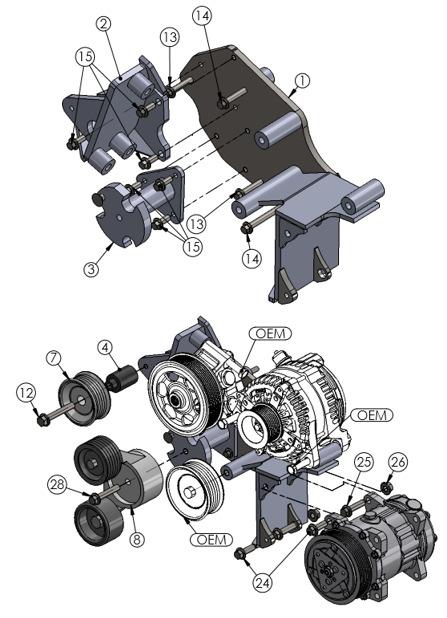
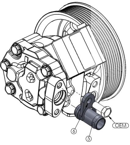
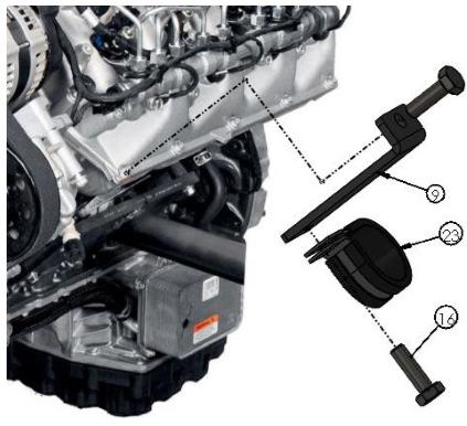
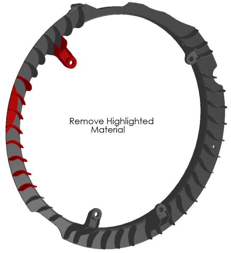
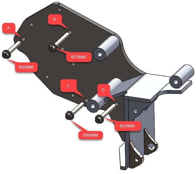
1 WITH DUAL ALTERNATORS This kit will NOT work on trucks equipped with adaptive steering. INSTALLATION NOTES 1. Disconnect negative batteries cables. Remove the air duct from the passenger side and the black rubber charge air tube from the driver s side. Remove the plastic cowling from the top side of the radiator.(14 clips total) Remove the P/S reservoir and coolant reservoir from the fan shroud, then remove the bolts and remove the top half of the fan shroud. 2. It is highly recommended the radiator be protected with cardboard or other suitable material. Remove the bolt holding the fan wire standoff to the engine then disconnect the fan wire. Remove the fan. Fan nut has right hand threads. Remove the OEM serpentine belt. Disconnect the wires from the alternator and remove it. Drain as much fluid as possible from the P/S reservoir then remove the return hose connecting the reservoir to the P/S pump. Remove the P/S pump from the bracket and lay it inside the fan shroud. It is not necessary to remove the steel pressure line from the P/S pump. Remove the P/S pump and alternator bracket from the engine. 3. Remove the plastic wire harness support from the engine and battery cables, it will not be reused. The battery cables will need to be separated from the alternator wire and rewrapped using the protective sleeves supplied in the kit. After the battery cables are rewrapped, secure the wires to the engine using the standoff (9) and loom clamp (23) with the front lower valve cover bolt. Use the other loom clamp (23), bolt (16) and nut (17) supplied to secure the battery cables to the radiator reservoir. Drain coolant reservoir and remove lower hose. Replace with hose (32) and clamps (33)(34). 4. Install the aftermarket AC onto the new bracket with bolts (24), (25), and nuts (26). Install the compressor and bracket assembly onto the engine with bolts (13) at locations A and C, and bolts (14) at locations B and D. Torque bolts to ft. lbs. Install the P/S bracket (2) onto the main bracket as shown in the illustration with bolts (15). Remove the suction hose elbow from the P/S pump and install the straight nipple (5) and hold down (6) reusing the OEM bolt. Install hose (19) onto the P/S pump with clamp (22). Install the P/S pump onto bracket (2) reusing the OEM bolts. The steel pressure line will need to be bent slightly in order to install the pump, but does not need to be removed. The steel line will run behind the water pump pulley. Install the alternator with the OEM bolts and connect the wires. 5. Remove the four crank pulley bolts and install the drive pulley with bolts (27). Install bracket (3) onto the main bracket with bolts (15). Remove the grooved idler from the OEM bracket and install it onto the new bracket with OEM bolt just below the alternator. Install idler (7) with bolt (12) and bushing (4) onto the new P/S bracket. Install the OEM belt as shown in the belt diagram. Install the aftermarket belt as shown. 6. Trim the fan ring as shown then install it back onto the engine. (There will only be three mounting locations) Install the all thread into the hole on the fan hub marked fan bolt and slide the black spacer over it. Install the threaded fan spacer (25) and the fan. Place the fan wire standoff over the all thread as the fan is being screwed on. Once the fan has been tightened, secure the fan wire standoff with the 8mm flange nut. Replace the fan shroud and radiator cover. Fit the P/S hose to the P/S reservoir and cut it to length. Secure with hose clamp (22). NOTE: It is the installers responsibility to make sure all hoses, wires, etc. and secure and away from any hot or moving parts.
2
3

4
5

6
Ford 6.8L, w/spider, 2000+
 DewEze Aiir Compressor Kiit 700554 Ford 6.8L, w/spider, 2000+ INSTALLATION INSTRUCTIONS 1. Disconnect the battery. 2. Drain the radiator. 3. Remove the air cleaner assembly. 4. Remove the upper radiator
DewEze Clutch Pump Kit Ford 6.2L Gas, A Pump, Side Port, 2011+
 DewEze Clutch Pump Kit 700512 Ford 6.2L Gas, A Pump, Side Port, 2011+ INSTALLATION INSTRUCTIONS 1. The installation of this kit requires trained decisionmaking concerning clearances, tying components together,
6. Remove OEM bolts from engine at locations A, B, and C. Lay the wiring off to the side.
 700359 DewEze Clutch Pump Kit #700359 Ford 5.4L, 6.8L w/ and w/o A/C AA mount 1999- INSTALLATION INSTRUCTIONS 1. Disconnect the battery. 2. Drain the radiator. 3. Remove the air cleaner assembly. 4. Remove
DewEze Clutch Pump Kit Ford 6.2L Gas, A Pump, Side Port, INSTALLATION INSTRUCTIONS 1. The installation of this kit requires trained decis
 DewEze Clutch Pump Kit 700564 Ford 6.2L Gas, A Pump, Side Port, 2014+ INSTALLATION INSTRUCTIONS 1. The installation of this kit requires trained decisionmaking concerning clearances, tying components together,
BLACKBIRD INSTALLATION SUPPLEMENT
 BLACKBIRD INSTALLATION SUPPLEMENT FOR 2003-7 FORD 6.0 LITER DIESEL SINGLE ALTERNATOR F-350, F-450, F-550, EXCURSION VERSION 7-07 Parts Description Blackbird Wiring Manual Installation Supplement 6.0 Liter
Included parts: 1 - New Bosch CP3 Pump 1 - HSM Pulley 1 - Serpentine Belt 1 - Pump Brackets/Hardware
 TROUBLESHOOTING: Please read and understand all installation instructions before proceeding with the installation. If you have questions during the installation of this product, please email H&S Motorsports
BLACKBIRD INSTALLATION SUPPLEMENT
 BLACKBIRD INSTALLATION SUPPLEMENT FOR5.3 AND 6 LITER VORTEC SUBURBAN/YUKON/SILVERADO VERSION 2-06 Blackbird Installation Supplement for GM 5.3 and 6 liter Vortec-Suburban/Silverado Parts Included in Installation
MTS-T4-6 APU Warranty SRT Time Guide (Caterpillar/Perkins Engines)
") MTS-T4-6 APU Warranty SRT Time Guide (Caterpillar/Perkins Engines) Air Conditioning System A/C Condenser Replacement RP9-011 A/C Condenser 2.5 RP9-027B Receiver/Dryer Filter 0.5 A/C Compressor Replacement
MTS-T4-6 APU Warranty SRT Time Guide (Caterpillar/Perkins Engines) Air Conditioning System A/C Condenser Replacement RP9-011 A/C Condenser 2.5 RP9-027B Receiver/Dryer Filter 0.5 A/C Compressor Replacement
BLACKBIRD INSTALLATION SUPPLEMENT
 BLACKBIRD INSTALLATION SUPPLEMENT 2008 GM 2500 AND 3500 6.6 DURAMAX DIESEL VERSION 5-08 Parts Included in Installation Kit Before beginning installation, check the parts kit thoroughly against the parts
Muncie Power Products
 Muncie Power Products CMKF08-6400-P8-AC 2008-2010 Ford F-250-550 6.4L Diesel W-WO/AC, WO/Dual Alt. WO/Vacuum Pump INSTALLATION NOTES 1. Using a 8mm socket or wrench, disconnect the negative battery cables
Ford E350, E450 Van LITER DIESEL ENGINE W/SINGLE OE ALTERNATOR TYPE B Uses TM-16, 4-3/4 Poly Groove Rear Port Compressor PARTS LIST
 2006-04 Ford E350, E450 Van 1784 6.0 LITER DIESEL ENGINE W/SINGLE OE ALTERNATOR TYPE B Uses TM-16, 4-3/4 Poly Groove Rear Port Compressor PARTS LIST 1 6m-1.0 x 15 Bolt 1 6m-1.0 x 45 Bolt 3 6m Flat Washer
BLACKBIRD INSTALLATION SUPPLEMENT
 BLACKBIRD INSTALLATION SUPPLEMENT FOR 2003-7 FORD 6.0 LITER DIESEL F-SERIES DUAL ALTERNATOR VERSION 10/07 Blackbird Installation Supplement for Ford 6.0. Liter Dual Alternator Parts included in the 6.0
1991 Nissan 240SX. 2.4L 4-CYL - VINS [F,M,S] 1991 ENGINES Nissan 2.4L 4-Cylinder
![1991 Nissan 240SX. 2.4L 4-CYL - VINS [F,M,S] 1991 ENGINES Nissan 2.4L 4-Cylinder](/thumbs/95/123571962.jpg "1991 Nissan 240SX. 2.4L 4-CYL - VINS [F,M,S] 1991 ENGINES Nissan 2.4L 4-Cylinder") NOTE: Use illustration for component reference. See Fig. 7. 1. Remove spark plug wires. Set No. 1 piston at TDC on its compression stroke. Remove vacuum hoses, electrical harnesses, connectors, and harness
NOTE: Use illustration for component reference. See Fig. 7. 1. Remove spark plug wires. Set No. 1 piston at TDC on its compression stroke. Remove vacuum hoses, electrical harnesses, connectors, and harness
TIMING BELT COMPONENTS EM 15
 ENGINE MECHANICAL COMPONENTS EM15 EM16 ENGINE MECHANICAL COMPONENTS (Cont d) ENGINE MECHANICAL EM17 REMOVAL OF (See pages EM15 and 16) 1. DISCONNECT CABLE FROM NEGATIVE TERMINAL OF BATTERY CAUTION: Work
Phone Fax
 Directions for Installation of ECS Paxton Supercharger Kit Disconnect battery Remove stock serpentine belt Remove stock belt tensioner, save the 2 bolts for later use on supercharger bracket Remove alternator
STEP 1 Disconnect the negative terminal from both batteries.
 TROUBLESHOOTING: Please read and understand all installation instructions before proceeding with the installation. If you have questions during the installation of this product, please email H&S Motorsports
Timing Belt. Removal 6A 27 ENGINE MECHANICAL (6VD1 3.2L)
") Removal 1.Disconnect battery ground cable. 2.Remove air cleaner assembly. 3.Remove radiator upper fan shroud from radiator. 4.Move drive belt tensioner to loose side using wrench then remove drive belt.
Removal 1.Disconnect battery ground cable. 2.Remove air cleaner assembly. 3.Remove radiator upper fan shroud from radiator. 4.Move drive belt tensioner to loose side using wrench then remove drive belt.
BLACKBIRD INSTALLATION SUPPLEMENT
 BLACKBIRD INSTALLATION SUPPLEMENT FOR 2008-105 FORD 6.4 LITER DIESEL F-SERIES VERSION 3/10 Parts Blackbird Wiring Manual Installation Supplement 6.4 liter Diesel Owner s Manual Includes Warrantee Registration
1996 Isuzu Truck Rodeo (2WD) V6-3165cc 3.2L SOHC (6VD1)
 V6-3165cc 3.2L SOHC (6VD1)") 1996 Isuzu Truck Rodeo (2WD) V6-3165cc 3.2L SOHC (6VD1) Service and Repair Notes REMOVAL STEPS Preparation: Battery ground cable 1. Radiator upper fan shroud Remove from radiator. 2. Cooling fan assembly
1996 Isuzu Truck Rodeo (2WD) V6-3165cc 3.2L SOHC (6VD1) Service and Repair Notes REMOVAL STEPS Preparation: Battery ground cable 1. Radiator upper fan shroud Remove from radiator. 2. Cooling fan assembly
INSTALLATION NOTES. 6. Add the 3/4 hose extension to the power steering reservoir to help keep the P/S hose away from the pump belt.
 YEAR:2017/ CURRENT INSTALLATION NOTES 1. Be sure to read and understand all available information including but not limited to instructions, warnings, sale terms, and warranties for the vehicle and all
Timing Belt. Removal ENGINE MECHANICAL (6VD1 3.2L) 6A-27
 6A-27") Removal 1. Disconnect battery ground cable. 2. Remove air cleaner assembly. 3. Remove radiator upper fan shroud from radiator. 4. Move drive belt tensioner to loose side using wrench then remove drive
Removal 1. Disconnect battery ground cable. 2. Remove air cleaner assembly. 3. Remove radiator upper fan shroud from radiator. 4. Move drive belt tensioner to loose side using wrench then remove drive
1997 Volvo 850 GLT. Fig. 2: Removing Drive Shaft, Engine Mount Bolt & Torque Arm (5-Cylinder) Courtesy of VOLVO CARS OF NORTH AMERICA.
 Courtesy of VOLVO CARS OF NORTH AMERICA.") Fig. 2: Removing Drive Shaft, Engine Mount Bolt & Torque Arm (5-Cylinder) 4. Remove front exhaust pipe nuts and springs. Remove front exhaust pipe bolts. Disconnect speedometer. Remove engine mounting
Fig. 2: Removing Drive Shaft, Engine Mount Bolt & Torque Arm (5-Cylinder) 4. Remove front exhaust pipe nuts and springs. Remove front exhaust pipe bolts. Disconnect speedometer. Remove engine mounting
10. SEPARATE COMPRESSOR (a) Remove the nut, 3 bolts compressor stay and compressor. HINT: Hang up the hoses instead of detaching.
 Remove the nut, 3 bolts compressor stay and compressor. HINT: Hang up the hoses instead of detaching.") 14108 ENGINE MECHANICAL REPLACEMENT 1. DRAIN ENGINE COOLANT(See page165 ) 2. SEPARATE BATTERY NEGATIVE TERMINAL 3. REMOVE VBANK COVER SUBASSY (a) Remove the 2 cap nuts and Vbank cover subassy. 4. REMOVE
14108 ENGINE MECHANICAL REPLACEMENT 1. DRAIN ENGINE COOLANT(See page165 ) 2. SEPARATE BATTERY NEGATIVE TERMINAL 3. REMOVE VBANK COVER SUBASSY (a) Remove the 2 cap nuts and Vbank cover subassy. 4. REMOVE
EG-34 ENGINE MECHANICAL TIMING BELT COMPONENTS FOR REMOVAL AND INSTALLATION
 EG34 TIMING BELT COMPONENTS FOR REMOVAL AND INSTALLATION EG35 TIMING BELT REMOVAL (See Components for Removal and Installation) 1. DISCONNECT NEGATIVE TERMINAL CABLE FROM BATTERY CAUTION: Work must be
INSTALLATION INSTRUCTIONS 97 FORD EXPEDITION
 INSTALLATION INSTRUCTIONS 97 FORD EXPEDITION 1. Read the instructions completely and carefully before you begin. Check the kit for proper contents (refer to the part s list and the picture diagrams). Before
SUPERCHARGER. ON-VEHICLE INSPECTION 1. INSPECT SUPERCHARGER OIL LEVEL HINT: With the engine cold, check the oil level on the dipstick.
 EG45 ONVEHICLE INSPECTION 1. INSPECT OIL LEVEL HINT: With the engine cold, check the oil level on the dipstick. (a) Park the vehicle on a level spot and turn the engine off. (b) 4WD: Remove the LH front
SHELBY GT500
 2007-2009 SHELBY GT500 Removal of Factory Unit WARNING: 1. Radiator fluid must be handled properly. Please observe local ordinances with regards to handling and disposal. 2. Allow vehicle and components
Timing Belt: Service and Repair Installation NOTE: Check the water pump for water leakage and the oil seal for oil leakage.
 1991 Daihatsu Truck Rocky L4-1589cc 1.6L SOHC Page 1 Timing Belt: Service and Repair Installation NOTE: Check the water pump for water leakage and the oil seal for oil leakage. Repair any water leakage
EG-37 ENGINE MECHANICAL TIMING BELT COMPONENTS FOR REMOVAL AND INSTALLATION 2JZ-GE
 ENGINE EG37 TIMING BELT COMPONENTS FOR REMOVAL AND INSTALLATION 2JZGE EG38 ENGINE 2JZ GTE ENGINE EG39 TIMING BELT REMOVAL (See Components for Removal and Installation) 1. REMOVE BATTERY AND BATTERY TRAY
Installation Manual v1.0: Twin CP3 Fuel Injection Kit Dodge 5.9L
 Installation Manual v1.0: Twin CP3 Fuel Injection Kit 2004.5-2007 Dodge 5.9L Figure 1 - Full Kit Photo 25 Figure 2 - Hardware Kit Please read all instructions before installation. This kit is not emissions
1996 Aerostar/Ranger/Explorer
 Page 1 of 11 Section 03-01B: Engine, 3.0L V-6 IN-VEHICLE SERVICE 1996 Aerostar and Ranger Vehicles Workshop Manual Water Pump SPECIAL SERVICE TOOL(S) REQUIRED Description Tool Number Fan Clutch Holding
WARNING: IF YOU ARE NOT EXPERIENCED IN THE AREA OF AUTOMOTIVE MECHANICS WE STRONGLY URGE THAT YOU REFER THIS INSTALLATION TO YOUR MECHANIC.
 INSTALLATION INSTRUCTIONS STILLEN SUPERCHARGER KIT 2003+ Infiniti G35 Materials supplied: See attached list Equipment needed: 1. Assorted sockets and wrenches 2. +,- Screwdrivers 3. Assorted pliers/ Clamps
All cores due 30 days after invoice date - no credit after 60 days.
 NO WARRANTY STATEMENT High performance parts & products no warranty policy: The purchaser understands and recognizes that high performance diesel products and services sold by INDUSTRIAL INJECTION SERVICE.
This information covers procedures for replacing the sealant for the crankshaft cover on the Volvo D16F engine.
 Volvo Trucks North America Greensboro, NC USA DService Bulletin Trucks Date Group No. Page 1.2008 216 50 1(17) Sealant Crankshaft Cover, Replacement D16F Sealant Crankshaft Cover, Replacement W2005773
REMOVAL & INSTALLATION
 REMOVAL & INSTALLATION TIMING BELT Removal (Esteem) 1. Disconnect negative battery cable. Remove right side engine under cover. Remove power steering and A/C compressor drive belts. 2. Remove A/C compressor
Highly Styled, Low Cost Serpentine Drive. Chrysler 383, 440 and 426 HEMI
 Highly Styled, Low Cost Serpentine Drive Installation Instructions Chrysler 8, 440 and 426 HEMI Kit #40720 (without Power Steering) Use 71.5" Serpentine Belt Kit #40725 (with Power Steering) Use 81.5"
2014 RAM C/V Tradesman
 Fig. 91: Suction Hose Ball Valve NOTE: View typical 14. Open the suction hose's ball valve to begin refilling the cooling system. 15. When the vacuum gauge reads zero, the system is filled. NOTE: On some
1995 Mitsubishi Montero LS. Ensure timing marks are aligned. Mark timing belt direction of rotation.
 TIMING BELT NOTE: Ensure timing marks are aligned. Mark timing belt direction of rotation. Removal 1. Disconnect negative battery cable. Drain engine coolant. Remove engine coolant reservoir tank, fan
SECTION 1D1 M162 ENGINE COOLING
 SECTION 1D1 M162 ENGINE COOLING CAUTION: Disconnect the negative battery cable before removing or installing any electrical unit or when a tool or equipment could easily come in contact with exposed electrical
POWER RACK AND PINION STEERING INSTALLATION
 by Randy Irwin 1955-57 POWER RACK AND PINION STEERING INSTALLATION Randy Irwin - Technical Writer Randy has been involved in the Chevy parts business for over 25 years. He is a wizard at creating, making
BD Venom Dual Fuel F O R D 6. 7 L P O W E R S T R O K E Installation Instructions
 U 21 March 2017 (1050470) Venom Dual Fuel Kit (I-00390) 1 DOWNLOAD ENHANCED INSTALL MANUALS AT dieselperformance.com BD Venom Dual Fuel 2 0 1 1-2 0 1 6 F O R D 6. 7 L P O W E R S T R O K E Installation
DODGE CUMMINS DUAL PUMP & DELUXE DUAL PUMP KIT
 SUBJECT: DODGE CUMMINS DUAL PUMP & DELUXE DUAL PUMP KIT Page 1 of 10 FITMENT: 2003 2007 Dodge Cummins with 5.9L KIT P/N: FPE-DPK-59-NP-[BK,BL,OG,RD], FPE-DPK-59-NP-DX [BK,BL,OG,RD], FPE-DPK-59-3K-[BK,BL,OG,RD],
BD Venom Dual Fuel F O R D 6. 7 L P O W E R S T R O K E Installation Instructions
 U 30 January 2017 (1050470) Venom Dual Fuel Kit (I-00390) 1 DOWNLOAD ENHANCED INSTALL MANUALS AT dieselperformance.com BD Venom Dual Fuel 2 0 1 1-2 0 1 4 F O R D 6. 7 L P O W E R S T R O K E Installation
Installation Manual v1.0: Twin CP3 Fuel Injection Kit Dodge 6.7L
 04/05/2012 Dodge 2010-2011 6.7L Twin CP3 701-900-2356-INST Installation Manual v1.0: Twin CP3 Fuel Injection Kit 2010-2011 Dodge 6.7L Figure 1 - Full Kit Photo 29 Figure 2 - Hardware Kit (800) 949-60002
REMOVAL 1. DISCONNECT CABLE FROM NEGATIVE BATTERY TERMINAL 2. REMOVE FRONT WHEEL RH. 3. REMOVE REAR WHEEL (for 4WD) (a) Move the select lever to N.
 (a) Move the select lever to N.") REMOVAL 1. DISCONNECT CABLE FROM NEGATIVE BATTERY TERMINAL 2. REMOVE FRONT WHEEL RH 3. REMOVE REAR WHEEL (for 4WD) (a) Move the select lever to N. (b) Check that the parking brake is released. (c) Remove
REMOVAL 1. DISCONNECT CABLE FROM NEGATIVE BATTERY TERMINAL 2. REMOVE FRONT WHEEL RH 3. REMOVE REAR WHEEL (for 4WD) (a) Move the select lever to N. (b) Check that the parking brake is released. (c) Remove
Scion FR-S ZN6. GTX2867R Gen2 (Internal Wastegate) Installation Instructions GPP P/N #
 Installation Instructions GPP P/N #") TURBO KIT Scion FR-S ZN6 Subaru BRZ ZC6 GTX2867R Gen2 (Internal Wastegate) Installation Instructions GPP P/N # 11518000 Vehicle Type Chassis Code Engine Code Transmission Model Year Scion FR-S DBA-ZN6
TURBO KIT Scion FR-S ZN6 Subaru BRZ ZC6 GTX2867R Gen2 (Internal Wastegate) Installation Instructions GPP P/N # 11518000 Vehicle Type Chassis Code Engine Code Transmission Model Year Scion FR-S DBA-ZN6
REMOVAL & INSTALLATION
 REMOVAL & INSTALLATION NOTE: For reassembly reference, label all electrical connectors, vacuum hoses and fuel lines before removal. Also place mating marks on engine hood and other major assemblies before
Body, front. Lock carrier with attachments, removing and installing
 Page 1 of 19 50-1 Body, front Lock carrier with attachments, removing and installing 1 - Hex bolt (6x) 45 Nm (33 ft lb) 2 - Hex bolt 45 Nm (33 ft lb) 3 - Hex bolt (4x) 10 Nm (7 ft lb) 4 - Hex bolts (2x)
EG 18 ENGINE MECHANICAL TIMING BELT EG5EK 01 COMPONENTS FOR REMOVAL AND INSTALLATION
 EG18 ENGINE TIMING BELT COMPONENTS FOR REMOVAL AND INSTALLATION EG5EK01 ENGINE EG19 EG20 ENGINE ENGINE EG21 EG22 ENGINE TIMING BELT REMOVAL EG5G101 1. REMOVE OIL PAN PROTECTOR 2. REMOVE ENGINE UNDER COVER
Ford 6.0L. Part #: Part #: BD GASKET PART# will be needed for this installation.
 1 BD EGR COOLER 2003-2007 Ford 6.0L Part #: 1090201 Part #: 1090202 PLEASE READ ALL INSTRUCTIONS BEFORE INSTALLATION BD GASKET PART# 1090002 will be needed for this installation. 2 K I T C O N T E N T
Installation Instructions for: TOYOTA 4.5L SUPERCHARGER SYSTEM
 Installation Instructions for: TOYOTA 4.5L SUPERCHARGER SYSTEM 1995-1997 Land Cruiser * PREMIUM FUEL REQUIRED * Magnuson Products LLC 1990 Knoll Drive, Bldg A, Ventura, CA 93003 (805) 642-8833 phone *
5.7L ENGINE PARTS BOOK. Not for. Reproduction
 5.7L ENGINE PARTS BOOK Engine Model: Engine Family: PSI, Industrial Engine Spec N.: 39004120-39004248 Parts Book Revision: December, 2015 TABLE OF CONTENTS SECTION PAGE CYLINDER BLOCK... 3-5 CYLINDER HEAD...
Timing Chain - Renew ( )
") «Escort 1991/1996 Table of Contents» «Group 21: Basic Engine» «Section 21-09: 2.0l DOHC 16V Engine» «REMOVAL AND INSTALLATION» Timing Chain - Renew (21 314 0) Special Tools 15-030 AUniversal flange holding
«Escort 1991/1996 Table of Contents» «Group 21: Basic Engine» «Section 21-09: 2.0l DOHC 16V Engine» «REMOVAL AND INSTALLATION» Timing Chain - Renew (21 314 0) Special Tools 15-030 AUniversal flange holding
2017+ L5P Duramax 3 ½ Down Pipe & EGR Fix Kit
 2017+ L5P Duramax 3 ½ Down Pipe & EGR Fix Kit Covers installation of PN s: WCF100630, WCF100829 Note: This Kit is for off road competition use only! Off Road Competition Use Tuning & Exhaust System is
INSTALLATION INSTRUCTIONS STILLEN SUPERCHARGER KIT Nissan 350Z P/N &
 Equipment needed: 1. Assorted sockets and wrenches 2. +,- Screwdrivers 3. Assorted pliers/ Clamps 4. Wire cutting/crimping tools 5. Thread locking compound (blue) 6. Solder gun/ shrink wrap (optional)
2/17/2017 Timing Belt Service and Repair, Removal and Replacement
 http://repair.alldata.com/alldata/article/display.action?componentid=64&itypeid=401&nonstandardid=0&vehicleid=39554&miles=&printfriendly=com 1/22 http://repair.alldata.com/alldata/article/display.action?componentid=64&itypeid=401&nonstandardid=0&vehicleid=39554&miles=&printfriendly=com
Illustrated Parts List for VMAC System V Ford F250-F350 Triton 5.4 L 3-valve (with 3 bolt crank pulley)
") Illustrated Parts List for VMAC System V900092 2008 Ford F250-F350 Triton 5.4 L 3-valve (with 3 bolt crank pulley) System V900102 2010-2008 Ford F250-F350 Triton 5.4 L 3-valve (with center bolt crank pulley)
Illustrated Parts List for VMAC System V900092 2008 Ford F250-F350 Triton 5.4 L 3-valve (with 3 bolt crank pulley) System V900102 2010-2008 Ford F250-F350 Triton 5.4 L 3-valve (with center bolt crank pulley)
Intake Manifold: Service and Repair Removal
 1992 Toyota Truck Pickup 2WD V6-180.5 2959cc 3.0L SOHC (3VZ-E) Copyright 2013, ALLDATA 10.52 Page 1 Intake Manifold: Service and Repair Removal NOTE: If removing and later reinstalling the fluid coupling
REMOVAL. 16. LOOSEN CRANKSHAFT PULLEY BOLT Using SST, loosen the pulley bolt. SST ( ), EM 20 SST TIMING BELT
, EM 20 SST TIMING BELT") EM20 REMOVAL EM11901 1. REMOVE NO.1 ENGINE UNDER COVER 2. DRAIN ENGINE COOLANT 3. REMOVE AIR CLEANER INLET 4. REMOVE AIR CLEANER ASSEMBLY 5. REMOVE NO.2 CYLINDER HEAD COVER 6. REMOVE IGNITION COILS (See
EM20 REMOVAL EM11901 1. REMOVE NO.1 ENGINE UNDER COVER 2. DRAIN ENGINE COOLANT 3. REMOVE AIR CLEANER INLET 4. REMOVE AIR CLEANER ASSEMBLY 5. REMOVE NO.2 CYLINDER HEAD COVER 6. REMOVE IGNITION COILS (See
All cores due 30 days after invoice date - no credit after 60 days.
 NO WARRANTY STATEMENT High performance parts & products no warranty policy: The purchaser understands and recognizes that high performance diesel products and services sold by INDUSTRIAL INJECTION SERVICE.
Air Commander Part No
 EASYSTEET Air Commander Part No. 26903 www.airliftcompany.com MN-510 (06506) EC 5206 Please read these instructions completely before proceeding with installation The oil level in the compressor must be
Retriever 5100G/P. 11/89 revised 10/02 FORM NO
 Retriever 5100G/P PARTS LIST Advance MODELS 56497000, 56497010 This parts list is for machines after serial number 353005 All models covered in this manual are OBSOLETE 11/89 revised 10/02 FORM NO. 56042216
Installation Manual v2.2: Twin CP3 Fuel Injection Kit Dodge 5.9L
 12/13/11 ATS Twin CP3 Kit 701-900-2272-INST Installation Manual v2.2: Twin CP3 Fuel Injection Kit 2003-2004 Dodge 5.9L Figure 1 - Full Kit Photo 26 Figure 2 - Hardware Kit 1 Please read all instructions
4. Remove (4) 10mm and (1) 7mm bolt that holds fascia at front corners, on each side
 10mm and (1) 7mm bolt that holds fascia at front corners, on each side") 2010 Camaro LS3 1. Disconnect battery ground 2. Remove front wheels 3. Remove (5) push pins and (5) #20 torx screws on inner front wheel well liners and remove liners on each side 4. Remove (4) 10mm and
2010 Camaro LS3 1. Disconnect battery ground 2. Remove front wheels 3. Remove (5) push pins and (5) #20 torx screws on inner front wheel well liners and remove liners on each side 4. Remove (4) 10mm and
REMOVAL AC 67. Using a clip remover, disengage the 6 clips and remove the front fender apron seal upper. (2WD)
") 67 PRE RUNNER 4WD: REMOVAL 1. DISCHARGE REFRIGERANT FROM REFRIGERATION SYSTEM (See page -18) 2. DISCONNECT CABLE FROM NEGATIVE BATTERY TERMINAL 3. REMOVE FRONT WHEEL LH 4. REMOVE NO. 1 ENGINE UNDER COVER
67 PRE RUNNER 4WD: REMOVAL 1. DISCHARGE REFRIGERANT FROM REFRIGERATION SYSTEM (See page -18) 2. DISCONNECT CABLE FROM NEGATIVE BATTERY TERMINAL 3. REMOVE FRONT WHEEL LH 4. REMOVE NO. 1 ENGINE UNDER COVER
GENSET ENGINE-G25/30. ITEM PART NO. DESCRIPTION QTY QTY REMARKS No. G25 G30
 ITEM PART NO. DESCRIPTION QTY QTY REMARKS No. G25 G30 1 CONTENTS SHEET DESCRIPTION PAGE NO. NO. E-1 CYLINDER BLOCK, LINER AND OIL SUMP 2 E-2 CYLINDER HEAD 6 E-3 PISTON AND CONNECTING ROD ASSY 10 E-4 CRANK
1.6L 4-CYL - VIN [E]
![1.6L 4-CYL - VIN [E]](/thumbs/81/84172348.jpg "1.6L 4-CYL - VIN [E]") 1.6L 4-CYL - VIN [E] 1993 Nissan Sentra 1993 NISSAN ENGINES 1.6L 4-Cylinder NX, Sentra * PLEASE READ THIS FIRST * NOTE: For engine repair procedures not covered in this article, see ENGINE OVERHAUL PROCEDURES
1.6L 4-CYL - VIN [E] 1993 Nissan Sentra 1993 NISSAN ENGINES 1.6L 4-Cylinder NX, Sentra * PLEASE READ THIS FIRST * NOTE: For engine repair procedures not covered in this article, see ENGINE OVERHAUL PROCEDURES
NISSAN 350Z 300HP ENGINE INTERCOOLED SUPERCHARGER INSTALLATION INSTRUCTIONS
 NISSAN 350Z 300HP ENGINE INTERCOOLED SUPERCHARGER INSTALLATION INSTRUCTIONS 2005 STEVE MILLEN SPORTPARTS, INC. All rights reserved. No part of this publication may be reproduced, transcribed, transmitted,
REMOVAL & INSTALLATION
 REMOVAL & INSTALLATION CAUTION: This application is an interference engine. Do not rotate camshaft or crankshaft when timing belt is removed, or engine damage may occur. TIMING BELT Removal 1. Raise and
Installation Manual for VMAC System V900095
 Installation Manual for VMAC System V900095 GMC/Chevrolet 1999 2002 6.0L Sierra and Silverado CK2500 and CK3500HD General Information... 3 Before You Start... 3 Additional Requirements... 4 Part 1: Preparing
1999 Nissan Altima GLE
 TIMING CHAIN CAUTION: If cylinder head is installed and timing chain is disconnected, DO NOT rotate camshaft or crankshaft; valves will contact pistons, resulting in bent valves. NOTE: Following procedure
General Removal & Installation Procedures for Most Heavy Duty Alternators
 General Removal & Installation Procedures for Most Heavy Duty Alternators MAY 2012 A. Removal Procedures 1. Disconnect negative battery cable. Note: there may be more than one negative battery cable if
 Page 1 of 6 Section 03-01C: Engine, 7.5L MFI 1996 Bronco/F-Series Workshop Manual IN-VEHICLE SERVICE Procedure revision date: 06/19/2000 Cylinder Heads Removal SPECIAL SERVICE TOOL(S) REQUIRED Description
Remove four nuts, then the cooling fan assembly.
 The DOHC and SOHC engines both use the same Service and Repair procedure from Isuzu. Make note that the DOHC and SOHC engines both use a single gear for the camshaft but use different alignment marks.
Installation Manual for VMAC System V900046
 Installation Manual for VMAC System V900046 GMC/Chevrolet 1999 2002 6.0L Sierra and Silverado CK2500 and CK3500HD General Information... 3 Before You Start... 3 Additional Requirements... 4 Part 1: Preparing
Vehicle Level Engine, Cooling and Exhaust Cooling System Water Pump Service and Repair Removal. Removal
 1 of 7 4/5/2008 11:18 PM Home Account Contact ALLDATA Log Out Help Select Vehicle New TSBs Technician's Reference Component Search: METRO TOYOTA OK 1994 Jeep Truck Wrangler L6-242 4.0L VIN S MFI Conversion
SERIES GARDEN TRACTORS 1992 PARTS CATALOGUE CONTENTS
 2000 SERIES GARDEN TRACTORS 1992 PARTS CATALOGUE CONTENTS PAGE No. 2000 SERIES GARDEN TRACTOR - CHASSIS, BODY PANELS, WHEELS, SEAT ETC 2 4 2000 SERIES PTO DRIVE, FRONT AXLE, ELECTRICS, MOUNTING FRAME AND
Charger, Magnum, 300C 5.7L & 6.1L Supercharger Installation Manual
 Charger, Magnum, 300C 5.7L & 6.1L Supercharger Installation Manual Arizona Speed and Marine, Inc. 6313 W. Commonwealth Ave, Chandler, AZ 85226 Phone: 480-753-0208 --- Fax: 480-753-0216 1. Table of Contents
INFINITI G35 298HP ENGINE INTERCOOLED SUPERCHARGER INSTALLATION INSTRUCTIONS
 INFINITI G35 298HP ENGINE INTERCOOLED SUPERCHARGER INSTALLATION INSTRUCTIONS 2005 STEVE MILLEN SPORTPARTS, INC. All rights reserved. No part of this publication may be reproduced, transcribed, transmitted,
ADJUSTMENTS Mazda MX-3. Fig. 1: Identifying Engine Code & Number Courtesy of MAZDA MOTORS CORP. VALVE CLEARANCE ADJUSTMENT
 Fig. 1: Identifying Engine Code & Number Courtesy of MAZDA MOTORS CORP. ADJUSTMENTS VALVE CLEARANCE ADJUSTMENT 1. No valve clearance adjustment is required, as hydraulic valve lash adjusters are used.
Procharger Stage II Intercooled Supercharger System (11-14 GT)
") Procharger Stage II Intercooled Supercharger System (11-14 GT) Installation Time: Approximately one day. Installed on 2012 Mustang GT 5.0/Manual Required Tools 3/8 Socket Set (Standard and Metric) 1/2
Procharger Stage II Intercooled Supercharger System (11-14 GT) Installation Time: Approximately one day. Installed on 2012 Mustang GT 5.0/Manual Required Tools 3/8 Socket Set (Standard and Metric) 1/2
SHEET DESCRIPTION PAGE NO. NO.
 CONTENTS SHEET DESCRIPTION PAGE NO. NO. E-1 CYLINDER BLOCK, LINER AND OIL SUMP 2 E-2 CYLINDER HEAD 6 E-3 PISTON AND CONNECTING ROD ASSY 10 E-4 CRANK SHAFT 12 E-5 TIMING GEAR COVER & SEALING 14 E-6 TIMING
Engine Replacement Procedures September Removal of the Complete Powertrain Assembly. Replacement Long Block Engine Preparation
 9 05-15 1 9 05-15 SUBJECT DATE Engine Replacement Procedures September 2015 Additions, Revisions, or Updates Publication Number / Title Platform Section Title Change Removal of the Complete Powertrain
Olson Kustom Works th St SE, Unit M, Monroe, WA (949)
") Olson Kustom Works 17404 147th St SE, Unit M, Monroe, WA 98272 (949)742-0613 Jesse@OKW-Inc.com TBSS SPECIFIC KIT INSTRUCTIONS Thank you for your purchase from OKW. If you have any questions about your
Olson Kustom Works 17404 147th St SE, Unit M, Monroe, WA 98272 (949)742-0613 Jesse@OKW-Inc.com TBSS SPECIFIC KIT INSTRUCTIONS Thank you for your purchase from OKW. If you have any questions about your
10/13/2016 5:33 PM. Radiator (B205L/R, B235R) To remove
 To remove") 1 of 15 Radiator (B205L/R, B235R) To remove 1. Disconnect the vent hose from the battery. Disconnect the positive and negative battery cables and remove the battery. Note the radio code where applicable.
1 of 15 Radiator (B205L/R, B235R) To remove 1. Disconnect the vent hose from the battery. Disconnect the positive and negative battery cables and remove the battery. Note the radio code where applicable.
This information covers the proper procedure for replacing the Volvo D16F engine in a VT or VNL chassis.
 Volvo Trucks North America Greensboro, NC USA Engine, Replacement DService Bulletin Trucks Date Group No. Page 10.2007 210 139 1(47) Engine, Replacement Volvo D16F VNL, VT W2005773 This information covers
Cut zip ties and remove 2 plastic wiring harness brackets.
 TROUBLESHOOTING: Please read and understand all installation instructions before proceeding with the installation. Included parts: 1 - New Bosch Cp3 Pump 1 - HSM Pulley 1 - Serpentine Belt 1 - Pump Bracket/
1 of 12 10/5/2015 8:11 AM
 1 of 12 10/5/2015 8:11 AM REMOVAL 1. Perform the fuel pressure release procedure See: Fuel Pressure Release > Procedures > Fuel System Pressure Release Procedure. 2. Recover the refrigerant from the refrigerant
2000 Toyota Truck Tundra. Timing Belt: Service and Repair
 Timing Belt: Service and Repair REMOVAL 1. REMOVE ENGINE UNDER COVER 2. DRAIN ENGINE COOLANT 3. REMOVE RADIATOR ASSEMBLY 4. REMOVE THROTTLE BODY COVER 5. REMOVE INTAKE AIR CONNECTOR ASSEMBLY 6. REMOVE
2000 Nissan Altima SE
 Removal 1. Release fuel pressure. See FUEL PRESSURE RELEASE. Drain coolant from radiator and cylinder block. Drain engine oil. Disconnect all necessary coolant hoses, electrical connectors, vacuum hoses,
Air Commander
 EASYSTREET Air Commander www.airliftcompany.com MN-507 (03206) ECN 3921 Please read these instructions completely before proceeding with installation. The oil level in the compressor must be checked BEFORE
48" and 52" Hyflo TM Un-Assembled Fans Assembly Manual
 48" and 52" Hyflo TM Un-Assembled Fans Assembly Manual The employees of Chore-Time Equipment would like to thank your for your recent Chore-Time purchase. If a problem should arise, your Chore-Time distributor
RigMaster Power Service and Repair Manual Document # S400909
 Document # S400909 S4.0 Enclosure Parts Breakdown for 2005 and newer To perform many of the repair procedures in this manual it may be necessary to remove a portion of the enclosure to gain access to components.
1 of 3 3/1/ :50 AM
 Fan Clutch Service and Repair, Removal and Replacement http://repair.alldata.com/alldata/article/display.action?componentid=76&... 1 of 3 3/1/2016 11:50 AM Coupling unit - Viscous Fan Service Repair No
WARNING: ALWAYS relieve fuel pressure before disconnecting any fuel related component. DO NOT allow fuel to contact engine or electrical components.
 4.0L V8 - VINS [K,U] Selected Block 1990 Lexus LS 400 For Lextreme Powertrain 2020 S. Hacienda Blvd. # D Hacienda Heights California 91745 Copyright 1998 Mitchell Repair Information Company, LLC Friday,
Timing Belt: Service and Repair
 2000 Isuzu Truck VehiCROSS (4WD) V6-3.5L Copyright 2006, ALLDATA 8.80 Page 1 Timing Belt: Service and Repair Removal 1. Disconnect battery ground cable. 2. Remove air cleaner assembly. 3. Remove radiator
Instant Chat off the main page of Or simply call our tech team at
 FRONT MOUNT INTERCOOLER 2008-13 STI 2014-04- 08 Thank you for purchasing this PERRIN product for your car! Installation of this product should only be performed by persons experienced with installation
* PLEASE READ INSTRUCTIONS PRIOR TO INSTALLATION
 XDP 6.0L Complete EGR Delete Kit w/up-pipe Item Number: XD169 PACKING LIST: 2 - Lined 3/4" Hose Clamps, 1-180 Coolant Tube, 1-3/4 Silicone Hose, 1 - Stainless Steel Up-pipe 1 - EGR Valve Block-Off Plate,
Service and Repair. a. Remove the 2 nuts and 2 upper radiator support. b. Lift out the radiator and cooling fan assembly.
 Service and Repair REPLACEMENT 1. SEPARATE BATTERY NEGATIVE TERMINAL 2. REMOVE AIR CLEANER INLET NO.1 3. DRAIN ENGINE COOLANT 4. REMOVE V-BANK COVER 5. REMOVE INTAKE AIR CONNECTOR PIPE 6. REMOVE ENGINE
PARTS LIST. Alternator Bracket A Main Alternator Bracket 1-P763-A... Idler Pulley. Pulleys. 5/16 x 7/8 SHCS (P/S Option)
") LS Custom Series Serpentine Kit LS Alternator & Air Conditioning Only Serpentine Kit Kit # 20090-08 LS Alternator, Air Conditioning & Power Steering Serpentine Kit Kit # 20095-08 11/10/16 PARTS LIST Alternator
LS Custom Series Serpentine Kit LS Alternator & Air Conditioning Only Serpentine Kit Kit # 20090-08 LS Alternator, Air Conditioning & Power Steering Serpentine Kit Kit # 20095-08 11/10/16 PARTS LIST Alternator