STADT DN. GB Instruction Manual
|
|
|
- Alexander McCoy
- 6 years ago
- Views:
Transcription


1 STADT DN GB Instruction Manual
2 2
3 1 Table of Content 1.1 Content 1 Table of Content Content Register of Illustrations Register of Tables Introduction Safety guidelines Important Advices Physical Basics Start Procedure / Igel Elektronik Soft Starter Methods Technical Data Introduction Hardware Bypass Front Panel Starter Selection Prior to Installation Soft Starter Selection Installation Installation and Prior to Installation Load Inside Delta Connection Inside Delta Connection with by-pass - right-hand rotation Inside Delta Connection Alternation of Motor Rotation Control Wiring Control Wiring with options Options UL, cul Installation Instructions Parameter Settings Menu Description (Overview) Parameter Description Adjustment of starting curves Selection of a pump control start curve (centrifugal pump) Start Curve Examples Internal Settings Fan Control Dip Switch Setting
4 8 Examples of Applications with Parameters Start-Up Procedure Trouble Shooting Motor and Starter Protection Frequently Asked Questions Technical Specifications Ordering Information Register of Illustrations phase asynchronous motor s typical current behavior phase asynchronous motor s typical start torque behavior phase asynchronous motor s reduced current behavior during start-up phase asynchronous motor s reduced behavior during start up Phase angle control and schematic layout of a soft starter Motor s Terminal Voltage Current Course Motor s Terminal Voltage with Current Limit Current Course with Current Limit Voltage Course Pulse-Start Current Course Pulse-Start Voltage Course with Energy Saving Current Course with Energy Saving Spannungsverlauf Sanftstopp Stromverlauf Sanftstopp Soft Stop with pump curves Soft-Start Characteristics Soft-Stop Characteristics Front View By-pass contactor Current course during start-up and soft stop phase Current course after the by-pass closes Current course of ISA-D A after by-pass closes Control wiring of a by-pass contactor By-pass contactor for frame size A By-pass contactor for frame size B By-pass contactor for frame size C By-pass contactor for frame size D By-pass contactor for frame sizes E, F, G Front Panel Example: LCD Arrangement Fans for additional ventilation Load Connection Plan (standard) Standard Motor Connecting Terminal Plate Inside Delta with right-hand by-pass
5 Table of Content 5-5 Inside Delta Connection Alternation of Motor Rotation Left-Hand Rotation Terminal Overview Control voltage and control inputs from the same source Control voltage and Control Inputs from the same source Terminal 21 Connections with various network Klemmenbelegung Profibus Terminal Overview Control Wiring Exp Control Wiring Exp Control Wiring Exp Control Wiring Exp Control Wiring Exp Control Wiring Exp Control Wiring Exp Control Wiring Exp Control Wiring with Line Contactor Control Wiring By-Pass Contactor Control Wiring with Reversing Contactors Wiring Diagram with Communication Remote/Local Start/Stop Wiring Examples Diesel-Generator Wiring Examples Brake Motor Wiring Examples Isolation Test Info Option D Choice of 4 pump control acceleration curves 0, 1, 2, Start Curve 4 (Torque) Pulse Start Initial Voltage Current Limit Acceleration time Stop Curves Deceleration time Dual Adjustment Energy Save Start Curves examples Start Curve examples Start Curve examples Internal Settings Voltage Control Dimension Drawings Size A Dimension Drawings Size A Dimensions Drawings Size A Dimensions Drawing Size B Dimension Drawing Size C (Special Design for marine/ul) Dimension Drawing 2 Size C (Sonderbauform) Dimension Drawing Size C (Standard) Dimension Drawing 2 Size C (Standard) Dimension Drawing Size D (Special Design for Marine/UL) Dimension Drawing 2 Size D (Special Design for Marine/UL) Dimension Drawing Size D (Standard) Dimension Drawing 2 Size D (Standard) Dimension Drawing 3 Size D (Standard 580A)
6 Table of Content Dimension Drawing 4 Size D (Standard) Dimension Drawing 5 Size D (Standard 820A) Dimension Drawing 6 Size D (Standard 820A) Dimension Drawing 7 Size D (Standard 950A) Dimension Drawing Size E Dimension Drawing Size F Dimension Drawing Size G Dimension Drawing Control Board ISA-D 2400, 2700, 3000A Dimension Drawing 1000V/105A Dimension Drawing 1000V/170A, 210A, 310A, 390A Dimension Drawing 1000V/460A Dimension Drawing UL/Marine Modell A Dimension Drawings UL/Marine Model A with by-pass Dimension Drawings UL/Marine Model A without by-pass Dimension Drawings UL/Marine Model A with by-pass Dimension Drawings UL/Marine Model 460A without by-pass Dimension Drawings UL/Marine Model 460A with by-pass Dimension Drawing UL/Marine Model 460A without by-pass Dimension Drawing UL/Marine Model 460A with by-pass Dimension Drawing UL/Marine Model 580, 820A without by-pass Dimension Drawing UL/Marine Model 580, 820A with by-pass Dimension Drawing UL/Marine Model 580, 820A without by-pass Dimension Drawing UL/Marine Model 580, 820A with by-pass Register of Tables 3-1 Front Panel Description LED Arrangement/Significance Operation Conditions Main Voltage Control Voltage Voltage Control Inputs Power Steps Line/Inside Delta Connection Analogue Output Control Wiring Options Power Selection for UL Restrictions Parameter Menu Description Motor FLA Parameters Description Main Parameters Description Starting Parameter Description Stop Parameter Description Dual Parameter Description Special Features Parameter Erklärung Fault Parameter Description I/O Parameter Description Communication Parameter Description Modbus Communication Parameter Description Profibus Statistical Data Description Settings
7 Table of Content 7-2 Switch Functions Display Modes special Parameter setting Technical Specifications Technical Specifications Technical Specifications Selection of normal and semi conductor fuses / Article Numbers Power Steps and Sizes Encasing dimensions: Size (mm) & Weight (Kg) Soft Starter Standards
8 Introduction 2 Introduction 2.1 Safety guidelines Read this manual carefully before operating the equipment and follow its instructions. Installation, operation and maintenance should be in strict accordance with this manual, national codes and good practice. Installation or operating not performed in strict accordance with these instructions will void manufacturer s warranty. Disconnect all power inputs before servicing the soft-starter and/or the motor. Prior to the installation, check and verify that no parts (bolts, washers, etc) will fall into the starter. Attention This product was designed and tested for compliance with IEC for class A equipment. The Soft starters comply to the UL classification Use of the product in domestic environments may cause radio interference, in which case the user may be required to employ additional mitigation methods. Utilization category is AC-53a or AC-53b. Form 1. For further information see Technical Specification. Warnings Internal components and P.C.B s are at Mains potential when the ISA-Start is connected to mains. This voltage is extremely dangerous and may cause death or severe injury if contacted. When the Soft starter is connected to Mains, even if start signal has not been issued, full voltage may appear on motor s terminals. Therefore, for isolation purposes it is required to connect an isolating device (C/B, switch, line contactor, etc) upstream to the SOFT STARTER. Starter must be properly grounded (except 8-22A) to ensure correct operation and safety. Check that Power Factor capacitors are not connected to the output side of the soft starter. Don t interchange the mains- and the motor- connections! 8
9 Introduction 2.2 Important Advices Object of the Manual This manual contains advices as well as basics and tips for the installation and commissioning of Igel Elektronik soft starters. The Igel Elektronik soft starter ISA-D is a motor control device for optimized starting and stopping of asynchronous and 3-phase-asynchronous motors. The manual describes all the Igel Elektronik soft starter ISA-D functions as well as the programming and fault research. Target group The manual is aimed at all users who deal with commissioning, service, the maintenance, planning and configuration of plants. Required basic knowledge General knowledge in the field of general electrical engineering is required for understanding this manual. Für die Installation und die Inbetriebnahme ist es erforderlich, dass nur geschulte Elektrofachkräfte die Geräte handhaben. Das Personal für die Inbetriebnahme und Wartung muss im Einsatz mit den Produkten geschult und erfahren sein. Validity This manual is valid for the Igel Elektronik soft starters, series ISA-D. It contains a description of the components that are valid at the time of publication. We reserve the right to include an updated product information leaflet with new components and new component versions. Standards and approvals The Soft Starter complies to the IEC/EN standard. All Igel Elektronik soft starters are developed and manufactured according to the IEC standards, which are part of the International Standard Organisation ISO. The Igel Elektronik soft starter ISA-D complies with IEC standard. For soft starters on board of ships additional certificates as GL (Germanischer Lloyd), LRS (Lloyd s Register of Shipping) or other independent certification organisations are available. If special certificates are required, please consult factory. 9
10 Introduction Disclaimer of liability The manufacture of this system or machine is responsible for ensuring the correct overall functioning. The manufacture of this soft starter cannot guarantee all properties of a system or machine not designed by the manufacture of this soft starter. The manufacture of this soft starter can also not assume liability of recommendations given or implied by the following description. No new guarantee / warranty or liability claims in excess of the general terms and conditions of the manufacture of this soft starter can be deduced from the following description. Information For technical questions please contact: STADT AS Molovegen 2 NO-6083 Gjerdsvika NORWAY Tel: Fax: info@stadt.no Web: 10
11 Introduction 2.3 Physical Basics 3-phase aynchronous motor 3-phase asynchronous motors are used in large numbers because their robust and simple design and low-maintenance operation, in commercial applications, trade and industry. There they propel many different applications (e.g. compressors, pumps). The problem is if switched on directly, during the start-up, the typical current and torque behaviour of the 3-phase asynchronous motors may negatively influence the feeding supply network and the load machine. The direct starting current of the 3-phase asynchronous motors are very high. This current may be 5 times to 15 times the size of the rated operating current. 7 to 8 times the size of the motor rated current is a typical value. The following disadvantage is that there is a higher load on the electrical supply network what means that the supply network must be dimensioned to this higher output during motor start-up phase asynchronous motor s typical current behavior Another disadvantage is the very high starting torque. The starting and stalling torque can usually be assumed to be between 2 and 4 times the rated torque. This means for the load machine that the starting acceleration forces in relation to rated operation result in increased mechanical load on the machine and the conveyed material. Thereby the machine s mechanic is more stressed and so there are higher costs because of application wear and maintenance. 11
12 Introduction phase asynchronous motor s typical start torque behavior Solution: Using the Igel Elektronik soft starter current and torque behavior during start-up can be optimally adapted to the requirement of the application. Operating mode of the Igel Elektronik soft starter The soft starter has got two antiparallel thyristors in each of the two phases (except ISA-A2P and ISA-B2P). There is one for the positive and one for the negative half wave. Using phase angle control and various control methods, the r.m.s. value of the motor voltage is increased from definable start voltage or start torque to the motor rated voltage within a selectable starting time. 3-phase asynchronous motor with soft start The voltage applied to the motor acts proportional to the motor current. Thus the factor of the voltage that is applied to the motor reduces the starting current. In relation to the voltage applied to the motor the torque behaves quadratic. The start torque is thus reduced quadratic based on the voltage applied to the motor. The reduction of the start torque will result in a smooth acceleration of the motor. 12
13 Introduction Example: With an 800 kw motor at 400V nominal voltage. Selected soft starter ISA-D I Motor s data: P: 800 kw I: 1400 A I Direct on-line start 7 x I e 9800 A M: 5090 Nm M Direct on-line start: 3 x M e n: 1500min -1 Set start voltage: 30% I Start is 30% of I Direct on-line start because I ~ U so I = 2940 A M Start is 9% of M Direct on-line start because M ~ U 2 so M = 1374 Nm The following graphs show the behavior of the starting current and torque of a 3-phase asynchronous motor while using a soft starter phase asynchronous motor s reduced current behavior during start-up 13
14 Introduction phase asynchronous motor s reduced behavior during start up Main advantages: the reductions of the start-up peak and so a lesser mains burden the reductions of the starting torque and so a lesser burden of the mechanical drive-line systems like chains, gearing mechanisms or V-belt. Upon completion of motor start-up, the thyristors are fully utilized, resulting in the complete network voltage being applied to the motor terminals. Since no motor voltage control is required during operation, the thyristors are bridged by bypass contacts. This reduces the waste heat developing during continuous operation which is caused by power loss of the thyristor. Therefore, the area around the switching devices heats up less. 14

15 Introduction The following graph shows the operation mode of an Igel Elektronik soft starter. 2-5 Phase angle control and schematic layout of a soft starter Application and use Applications and selection criteria: The soft starters are an alternative for star-delta starters, frequency converters, slip-ring motors and transformer starters. Their major benefits are smooth starting and stopping, uninterrupted changeover without current peaks that would stress the power supply, and their compact dimensions. The soft starters ISA-A, ISA-A2P, ISA-DS and ISA-D contain additional an integrated motor protection function. 15
16 Introduction Applications: Possible applications include: o Pumps o Compressors o Conveyor belt o Powered roller conveyors o Ventilators/Fans o Hydraulic pumps o Stirres o Centrifugal machines o Milling machines o Mills o Crushers o Disk saws/ribbon saws o shredder o Screw conveyor o Advantages: Centrifugal pumps, reciprocating pumps: o Water hammering in pipe systems is avoided o Pressure shocks on valves are avoided o Lesser service costs for installations Conveyor belts and systems: o slower acceleration/braking spare the machines Stirrers, mixers: o Reduced starting current Fans: o Reduced stress on transmissions and V-belts Boundary conditions for storage and operation Permissible ambient temperature for: - Storage -25 C to +70 C - Operation 0 C to +40 C, from 40 C with derating Permissible relative air humidity: 10 to 95 % Maximum permissible installation height: 1000m, from 1000m with derating Caution: Please ensure that no liquid, dust or conductive parts enter the soft starter! 16
17 Introduction 2.4 Start Procedure / Igel Elektronik Soft Starter Methods Soft Start with voltage ramp The motor starts with the adjusted initial voltage and gets an additional linear rising voltage. At this kind of start-up the starting current, which depends on the adjusted rampup time and the driven loading, reaches 2 to 4 times of the motor s rated current. 2-6 Motor s Terminal Voltage 2-7 Current Course Soft Start with Starting Current Limit In this case the Motor also starts with the adjusted initial voltage and gets an additional linear rising voltage. When the adjusted starting current is reached the voltage ramp stops and the terminal voltage keeps constant till the motor s power consumption sinks under the adjusted starting current. The ramp-up time gets lengthened with the time of current limit. 2-8 Motor s Terminal Voltage with Current Limit 2-9 Current Course with Current Limit When the motor get started with Starting Current Limit, you have to keep attention that the motor is able to get an acceleration torque against the loading. If you select a too low starting current it could be possible that the motor or its soft starter gets a thermal overload. 17
18 Introduction Soft Start with Pulse Start If driving elements have a too high frictional or inertial torque there is the possibility to use the pulse-start. During the pulse-start the terminal voltage gets limited to 80% of the rated voltage in a time domain from 0.1 to 1 sec. After that the soft-start begins with the adjusted starting voltage and the adjusted Ramp-up-time Voltage Course Pulse-Start 2-11 Current Course Pulse-Start Energy Saving Some electronic soft starters contain the function energy saving. This function improves the cos φ of the motor by controlling the terminal voltage of the motor by continuous phase angle in part-load- or idle-speed-range of the motor. In consideration of the losses in the soft starter there is only a real energy saving in part-load-ranges possible which are never under 60% of the rated loading of the motor. During an alternation of stress the motor s terminal voltage gets immediately adjusted by the soft starter, so as to prevent a revs breaking in. Disadvantage of the energy saving function is a load of the mains with harmonics by phase angle Voltage Course with Energy Saving 2-13 Current Course with Energy Saving 18
19 Introduction Soft Stop All Soft Starter of the ISA series contain the soft stop function. By courtesy of this function you get a voltage-controlled run-out of the motor which prevents an abrupt stopping of the motor above all in pump applications. In all cases the function Soft Stop lengthens the motor s natural run-out and works only during load torque. By courtesy of lowering of the motor-terminal-voltage you get a field weakening which after all implicate a rising of the motor current over the rated motor current Spannungsverlauf Sanftstopp 2-15 Stromverlauf Sanftstopp Soft Stop with sepcial Pump Curves When liquid is pumped to a higher flat or to a duct system with higher pressures and the pump get turned off, big kickbacks (water hammer) accrue. A normal soft starter s run out ramp can only reduces this phenomenon in essentially because with a voltage reduction of 20% the water column brings the pump to a standstill. The special pump software enables the pump run-down until the check valve closes softly and so it decreases the wear out of the duct system effectively. End Switch The load of the water column closes the valve before the voltage can get reduced to zero. After that the pump rotates without load until the end of the adjusted run-out ramp. The end switch enables the immediate motor stop after the valve was closed Soft Stop with pump curves 19
20 Technical Data 3 Technical Data 3.1 Introduction The ISA-D is a highly sophisticated and reliable starter design for smooth starting and stopping of 3-phase asynchronous motors (squirrel cage induction motors). It provides the best method of reducing current and torque during motor starting. The ISA-D motor starts the motor by supplying a slowly increasing voltage to the motor, providing soft start and smooth acceleration, while drawing a minimum current necessary to start the motor. The third generation, microprocessor based digital circuitry provides unique features like pump control, slow speed, electronical reversing and accurate motor protection with optional insulation protection, thermistor input, by-pass preparation (option 9) etc. reducing heat dissipation and saving energy. The optional RS 485 communication (Modbus and Profibus protocol) enables parameter setting, control and supervision. Up to 32 motor soft starters can optional be connected. 3-1 Soft-Start Characteristics 20
21 Technical Data 3-2 Soft-Stop Characteristics The soft stop characteristics may be used for the controlled pump or motor run-outs with high frictional load. The Igel soft starters ISA-D are designed to operate under normal as well as heavy duty start-up conditions. For frequent starts or starts at maximum ratings a larger sized starter should be selected. For long starts, soft stops and pump run-outs a PTC should be installed in the motor windings which only works during run-out when current load occurs. Do not install any capacitive loads (e.g. compensation) between soft starter and motor. When soft starters are used do not incorporate any active filters. 21
.")
22 Technical Data 3.2 Hardware 3-3 Front View A motor soft starter is built up with a few main components: Printed circuit board, thyristors, housing, connecting terminal and fans (for higher rated current). The main circuit incorporates 3 antiparallel switched thyristor units. The control circuit board controls the motor current. Using a soft starter the low motor voltage, low motor current as well as low torque behaviour during the start up can be optimally used. The ISA-D incorporates a digital control circuit. 3.3 Bypass Under normal conditions the heat dissipated by an electronic soft starter causes heating of the enclosure and energy loss. The heating and losses can be eliminated by the use of an external bypass contactor which will by pass the ISA-D after completion of the start-up. In this case the voltage protection functions will be maintained, except the current protection, as the current will not flow through the internal current transformers after the bypass closes. In order to maintain current protection after the by-pass contactor closes, option 9 must be ordered. 3-4 By-pass contactor 22
23 Technical Data Note: The soft starter sizes from 950A and all 1000V Soft Starters must be external supplied with bypass contactor. Bypass preparation is standard in models ISA-D A. 3-5 Current course during start-up and soft stop phase All current protections are maintained and the CT s also measure the current after the by-pass closes. 3-6 Current course after the by-pass closes Note: After the by-pass closes a soft starter without preparations for by-pass contactor (no option 9), will not maintain the following protections: under current, overload, short circuit. 23
24 Technical Data 3-7 Current course of ISA-D A after by-pass closes The soft starter sizes from 950A will be supplied without by-pass preparation. The by-pass contactor has to be installed by the customer. Current transformers CT1 and CT2 are supplied separately and must be connected to the ISA-D as shown below. If the connection is as shown all protection functions are maintained also after by-pass is closed. Control wiring by-pass contactor 3-8 Control wiring of a by-pass contactor 24
25 Technical Data Preparation for by-pass contactor (option 9) Frame Size A (8 72 A) The soft starters will be factory supplied, three additional terminals are added, marked L 1b, L 2b, L 3b. These terminals are connected after the internal CT s intended for connection to the by-pass. 3-9 By-pass contactor for frame size A Frame Size B (Old and New A) Old Additional set of bus-bars can be field mounted on the line side, after the CT s, so that the by-pass contactor could be connected to L 1b, L 2b, L 3b (option). New Additional set of bus-bars is built-in while the line side is on top, the motor side is at bottom with the by-pass terminals L 1b, L 2b, L 3b By-pass contactor for frame size B 3-11 By-pass contactor for frame size B New 25
26 Technical Data Frame Size C ( A) Additional set of bus bars can be field mounted on the line side, after transformer marked L 1b, L 2b, L 3b. The by-pass cables should be connected to these bus bars By-pass contactor for frame size C Frame Size D ( A) Additional set of bus bars can be field mounted on line side, after transformer marked L 1b, L 2b, L 3b. The by-pass cables should be connected to these bus-bars By-pass contactor for frame size D Note: Starter frame sizes C and D can be field modified to have line and load bus bars at the bottom. (Contact Igel Elektronik for further information). 26
27 Technical Data 950A to 3000A Additional set of bus bars can be field mounted on line side, after transformer marked L 1b, L 2b, L 3b. The by-pass cables should be connected to these bus-bars By-pass contactor for frame sizes E, F, G Note: Connect as follows: - Line to L1, L2, L3 - By-pass contactor, Input to L 1b, L 2b, L 3b, Output to U, V, W - Motor (load) to U, V and W Attention: Do not interchange line and load connections. 27


28 Technical Data 3.4 Front Panel 3-15 Front Panel Keypad Mode Select Store Reset Provides selection of the following modes: % rated motor current Main Parameters Start Parameters Stop Parameters Dual Adjustment Parameters EN.Save &SL SPS Parameters Fault Parameters I/O Programming Parameter Communication Parameter Statistical Data To select function within each mode. To increase adjusted parameters. Press momentarily and continuously. On side Statistical Data function scroll forward. To decrease adjusted parameters. Press momentarily and continously. On side Statistical data function scroll back To save. To reset the soft starter after fault has been removed, and allows restarting. 3-1 Front Panel Description 28
29 Technical Data LED Arrangement On Start Run S.Stop Stop E.Save/Slow D.Adj./Rev. Fault Significance Lights when control supply is connected to the starter Lights up when during start up process, indication the motor supply voltage is ramping up. Lights up after completion of starting process, indicating that motor is receiving full voltage. Flashes during 1/6 rotation speed. Lights up during soft Stop process, indication the motor supply voltage is ramping down. Lights up when motor is stopped. Lights up when energy save is in operation, flashes when motor is running at 1/6 rotation speed. Lights up when Dual Adjustment is in operation; flashes when motor is running in the reverse direction at 1/6 rotation speed. Lights up upon operation of any of the built-in protection. Flashes upon alarm of the isolation alarm relay (option). 3-2 LED Arrangement/Significance LCD Arrangement Two lines of 16 alphanumeric signs, four selectable languages: English, German, Spanish, French, (see language selection) Upper line displays funtions. Lower line displays setting and measured values. Example: CURRENT LIMIT 390% 3-16 Example: LCD Arrangement 29
30 Starter Selection 4 Starter Selection 4.1 Prior to Installation Make sure that fuses and circuit breakers of the main electric circuit are rated to oprate under direct start conditions and under the local short circuit conditions. Please order separately. Select the circuit breaker (Trip selection) according to the harmonic load of the starting current. General calculation is 2 times In (see table). 4.2 Soft Starter Selection 660Motor Current and Starter Settings Select the soft starter according to motor s Full Load Ampere as indicated on its nameplate even if the motor is never fully loaded. The ISA-D is designed to operate under the following maximum conditions: Ambient Temperature in C Start Current Accelera tion Time Starts per hour % In 30 sec 4 starts per hour at maximum ratings. Up to 60 starts per hour at light load applications. (Contact factory) 4-1 Operation Conditions Note: For trip operation, the maximum starting current should be considered as the Full Load Ampere. 2. Main Voltage (line to line) Thyristor s PIV rating, internal circuitry and insulation defines four voltage levels: Voltage Tolerance V 45-65Hz % V 45-65Hz % V 45-65Hz % V 45-65Hz % 1000V (Consult factory) % 4-2 Main Voltage 30
31 Starter Selection 3. Control Voltage The control voltage operates the electronical circuit and the by-pass-contacts. Two voltage levels are available: Voltage Tolerance V 45-65Hz (Standard) % V 45-65Hz % 110 VDC % 4-3 Control Voltage 4. Control Inputs Control Input Voltage (start, stop etc.) can be the same as Control Supply above, or AC/DC by special order. Voltage Tolerance V 50-60Hz (standard) +10 % V DC +10 % 24 V 50/60Hz +10/-15% 24 V DC +10/-15% 48 V 50/60Hz +10/-15% 48 V DC +10/-15% 4-4 Voltage Control Inputs 31
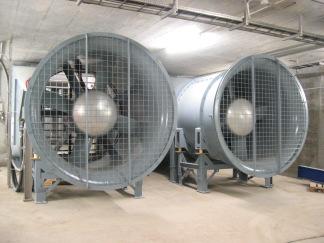
32 Installation 5 Installation 5.1 Installation and Prior to Installation The motor rated current has to be lower or according to the current of the soft starter while the net voltage has to comply with the values on the nameplate. Mounting The soft starter has to be mounted vertically. Allow sufficient space above and below the starter for suitable airflow. It is recommended to mount the soft starter directly on the rear metal plate of the switchgear for better heat dissipation. Do not mount the starter near heat sources. Protect the starter from dust and corrosive atmosphere. Note: For harsh environments it is recommended to order the starter with option 8. Ambient Conditions The soft starter ISA-D is rated to operate over a temperature range of -10 C to +50 C. The non condensed humidity inside the housing should not exceed 95%. Die Verlustleistung am Sanftanlasser beträgt maximal 0,8% der angeschlossenen Leistung. Als Näherungsformel kann 3x des Stroms in Watt angenommen werden. Example: motor s current is 100 A x 3 = 300 watts heat dissipation Important note: In case of frequent motor starts the cabinet should be built for higher dissipation. The internal enclosure heating can be reduced by using additional ventilation. 5-1 Fans for additional ventilation 32
33 Installation Calculating the enclosure size for non-ventilated metal cabinets: Surface (m²) = 0,12 x total heat dissipation* (W) 60 max. ambient temperature *heat dissipation of all cabinet equipment. Note: Using a plastic cabinet a bypass contactor must be used. Voltage Spike Protection Voltage spikes may cause malfunction of the soft starter and damage the thyristors. When expected, use suitable protection such as Metal Oxid Varistors. (Consult factory for further details.) Metal Oxid Varistors (MOV) are already built in soft starters sizes B E for protection against voltage spikes. When higher spikes are expected for size A, use external protection. (Please consult factory.) Short circuit protection Protect the thyristors in the ISA-D by semi-conducter fuses with I²t-values: Dimension of protection fuses, see chapter 14, Technical Data. Warnung When lines voltage is connected to the starter, even if the start signal has no been initiated, full voltage may appear on the output terminals and on the starter s load terminals. Therefore, for isolation purposes it is required to connect a switch respectively a line contactor upstream to the soft starter. Power factor correction capacitors must not be installed on starters load side. When required install capacitors on starter s line side with a 2 m cable. 33
34 Installation 5.2 Load ) ) 5-2 Load Connection Plan (standard) The soft starter incorporates two main voltage contacts (depending on the size of the soft starter): - bus bar connections - screw terminals The terminals L1/L2/L3 will be connected to the line. The terminals U/V/W are connected to the motor. 1) For short circuit protection use fuses or circuit breaks. For type 2 conditions use semi-conductor fuses. 2) For emergency stop a main contactor must be installed. 34
35 Installation 5.3 Inside Delta Connection When the ISA-D is installed Inside Delta, the individual phases of the ISA-D are connected in series with the individual motor windings (6 conductor connections as with the star-delta starter). The ISA-D must only conduct about 58 % (=1\ 3) of the rated motor current. This allows the use of a significantly smaller ISA-D. Note that although when connected Inside Delta the current is reduced by 1.73 ( 3), you should choose an ISA-D as if current is reduced only by 1.5. (1/1.5=0.667=67%) For example: For a motor with a rated current of 870A motor, a 950A starter will be selected to operate In-Line. For Inside Delta ISA-D, we calculate (870 x 67% = 580A) and select a 580A starter. 5-3 Standard Motor Connecting Terminal Plate Notes on Inside Delta Connection Inside Delta requires 6-wires to the motor. Wrong motor connection might cause serious damage to the motor windings. When installing the ISA-D Inside Delta it is highly recommended to use a contactor in series to the ISA-D or upstream (after motor protection) in order to avoid a damage to the motor if the ISA-D short circuits. The sinusoidal shape of the current might be imperfect. As a result, higher harmonic content is incurred (THD), which may be twice the THD value as in the standard In-Line connection. Motor heat may increase (due to the higher THD). Phase sequence to the input of the ISA-D (L1, L2 & L3 terminals) must be correct. Otherwise, PHASE SEQUENCE fault will trip the ISA-D immediately. Higher torque can not be obtained. 35
36 Installation The following factory preset features and functions are not active when Inside Delta mode is configured: o PULSE START o Curve selection (CURVE 0!! only). o EN. SAVE and SL. SPD (energy save and slow speed) o PHASE SEQUENCE in off mode When using INSIDE DELTA configuration, current wave shape is different than that in LINE configuration. This difference casus the current RMS value of the INSIDE DELTA configuration to be lower than that of LINE configuration assuming both have the same amplitude. In order to best protect the SCRs in the INSIDE DELTA we do not allow the amplitude of the current to be higher than that in LINE connection. Therefore the current RMS value expected for the same setting of the CURRENT LIMIT is lower by 10 ~ 30% than that in LINE connection. Note : For a high starting torque process, it is recommended to use the ISA-D in the In Line connection. When using Inside Delta connection: It is highly recommended to use a line contactor in order to avoid possible damage of the motor if the SCR is short circuited in the ISA.D. If the ISA-D is connected Inside the Delta, motor terminals are live (full voltage) even when the contactor is open. Motor connection in Delta mode without ISA-D Motor Connections: ASA (USA) BS VDE IEC T1 T4 A2 A1 U X U1 U2 T2 T5 B2 B1 V Y V1 V2 T3 T6 C2 C1 W Z W1 W2 36
37 Installation 5.4 Inside Delta Connection with by-pass - right-hand rotation Right-hand Rotation 5-4 Inside Delta with right-hand by-pass WARNING! False connection of the motor or soft starter may cause considerable damages of the motor and the soft starter! 37
38 Installation 5.5 Inside Delta Connection Alternation of Motor Rotation The line connections L1, L2, L3 cannot change the direction of motor rotation. In case of Inside Delta Connection the protection function Phase Sequence can not be switched off. A change of motor rotation can only be realised as follows: (Exchange motor windings U1 for V1 and motor windings U2 for V2.) Left-hand Rotation 5-5 Inside Delta Connection Alternation of Motor Rotation Left-Hand Rotation WARNUNG! False connection of the motor or soft starter may cause considerable damages to the motor and the soft starter! 38
39 Installation The soft starter should always be selected according to the motor s FLA and start procedure. For the Inside Delta Connection in series connection power will be multiplied by 5. Soft Starter Type max. rated motor current motor KW 400V (line connection) motor KW 400V (Inside Delta Connection) ISA-D ISA-D ,5 11 ISA-D ,5 ISA-D ISA-D ISA-D ,5 ISA-D ,5 ISA-D ,5 ISA-D ,5 ISA-D ISA-D ISA-D ISA-D ISA-D ISA-D ,5 ISA-D ISA-D ISA-D ISA-D ISA-D ISA-D ISA-D ISA-D ISD-D ISA-D ISA-D Power Steps Line/Inside Delta Connection 39
 are required to power the incorporated control and by-pass contacts.")
40 Installation 5.6 Control Wiring 5-7 Terminal Overview Control Voltage Terminals V or V, 50 / 60 Hz (as indicated on nameplate) are required to power the incorporated control and by-pass contacts. This voltage can be from a grounded line, control transformer or a Trenntrafo. Upon DIP-switch the voltage steps 110 V/ 220 V can be changed. 110V/DC can be supplied by special order for starter sizes B-F. Note: It is recommended that terminals 1 3 be always connected to the control supply. 40
41 Installation Control voltage and control inputs from the same source. Note: Control supply must be protected by 6A fuse. 5-8 Control voltage and control inputs from the same source Seperate sources for control voltage and control input. Note: Control supply must be protected by 6A fuse. 5-9 Control voltage and Control Inputs from the same source 41
42 Installation Fan s Supply Voltage Terminal 2 An internal junper, connected between terminal 2 and fan enables three modes of operation. Fro fan power consumption, see technical specification. Continuous mode (factory set) Fan operates as long as control supply is connected to terminals 1 and 3. External control mode Fan operates as long as control voltage of terminal 1 is connected to terminal 2. Automatic mode Fan begins operation when start signal is iniated and stops approximately 5 minutes after start signal. When stop respectivel soft stop signal is initiated the fan begins operation and stops after 5 minutes. Connect internal jumper right position of terminal J1 (C). Warning Automatic mode may be used only if by-pass contactor is directly controlled by the ISA-D end of acceleration contact. Control Inputs Incorporating opto-couplers to isolate the microprocessor circuitry The standard soft starter is supplied for V, 50/60 Hz, Control Supply and Control Input voltage. By special order Control Inputs may be supplied for voltage levels of V AC or DC. Stop Terminal 4 Input from one normal close (N.C.) contact. To stop the motor disconnect control voltage from terminal 4 for at least 250 msecs. Soft Stop Terminal 5 Input from one normal close (N.C.) contact. To soft Stopp the motor disconnect control voltage from terminal 5 for at least 250 msecs. Note: If soft stop is not required, connect a jumper between terminals 4 and 5. Start Terminal 6 Input from one N.O. contact. To start the motor connect control voltage to terminal 6 for at least 250msecs. Note: 1. Motor will start only if terminals 4 and 5 are connected to control voltage. 2. Reset after fault is not possible as long as a start signal is present. 42
43 Installation Energy Saving / 1/6 of Nominal Speed / Reset Terminal 7 Input from a N.O. contact - selection between above functions is made from the keypad or through the communication (Modbus or Profibus). When ENERGY SAVE function is selected - connect terminal 7 to control input voltage by a jumper for automatic operation, upon load decrease. When connected through a N.O. contact, closing the contact operates Energy Save. When SLOW SPEED function is selected - connect control input voltage to terminal 7 before starting. When start command is initiated motor will run at 1/6 nominal speed for 30 seconds maximum. Closing terminal 7 while motor is running will not have any effect. When RESET function is selected - connect terminal 7 to control input voltage (use a N.O. momentary contact) to reset the ISA-D. Dual Adjust / Reverse/ Reset Terminal 8 Input from a N.O. contact. Selection between above functions is made from operating board or communication (see I/O Programming) When DUAL ADJUSTMENT function is selected - connect terminal 8 to Control Input voltage to operate the ISA-D with the DUAL ADJUSTMENT characteristic. DUAL ADJUSTMENT characteristic is programmed. You can switch between the primary and DUAL ADJUSTMENT settings before and/or during starting. When dip switch #3 is set to on, DUAL ADJUSTMENT operates as D.ADJ.:GENERATOR PARAMETERS. Use this mode if the normal starting process fails, i.e., SHORTED SCR or WRONG CONNECTION faults occur and, after testing, operator is sure that SCRs, motor and motor connections are not faulty. Attention: When starting motor from Diesel generator or weak power set DIP Switch #3 On. Connect terminal 8 to control voltage to operate starter with generator parameters. When SLOW SPEED REVERSE function is selected - connect Control Input voltage to terminal 8 to reverse direction. In order to operate in SLOW SPEED REVERSE, terminal 7 must be programmed as SLOW SPEED and Control Input voltage must be connected to terminal 7 as well. You can give the reverse command before the motor is started or during operation at SLOW SPEED. Connecting Control Input voltage to terminal 8 before motor is started, starts the motor in reverse direction. Connecting Control Input voltage while motor is running at SLOW SPEED stops the motor for sec (according to motor size) before reversing its direction. Control voltage neutral Terminal 9 Common for terminals 4, 5, 6, 7, 8. Note: When control supply and control input voltage are from the same source, connect a jumper between terminals 3 and 9. 43
44 Installation Immediate/Shear-pin Relay Terminals Voltage free (Ausgeführt als Wechsler) 8A, 250V/AC, 2000VA max. Selection between functions is made through communication (siehe I/O Programming). Programmable functions: 1. Immediate relay, changes it s position upon start signal and in case of motor stop (end of soft stop process). When immediate relay is selected, the contact changes its position upon Start signal. The contact returns to its original position on Stop signal, in case of fault or upon control supply outage. When soft stop is operated, the contact returns to the original position at the end of the soft stop process. The immediate contact incorporates ON & OFF delays from 0 60 secs. each. The immediate contact con be used: To release a motor break. For interlocking with other systems. For signaling. To switch from standard to dual adjustment settings with a time of delay from start signal 2. Shear-pin / O/C relay, changes position upon shear-pin detection When O/C shear-pin relay is selected, the contact changes position upon shear-pin detection. Starters trip can be dalyed 0 5 secs. The O/C Shear-Pin contact can be used: For interlocking with other systems For signaling. with delay for operating a reversing combination. When shear-pin is detected thus allowing clearing a jam condition for e.g. for a shredder. Fault Relay Terminals Voltage free 8A, 250V/AC, 2000VA max., selection between functions is made through communication (see I/O Programming). The relay changes its position on fault when internal protection functions or external fault occur. The relay is programmable to the following functions: 1. Standard Relay Upon alarm the realy is energized upon fault. The contact returns to its original position after fault has been removed and starter was reset Spannungsicheres Relais (Trip-fail safe) relay The relay is engergized immediately when control supply is connected and de-energizes upon fault or disconnection of control voltage. 44
45 Installation End of Acceleration Contact Terminals Voltage free 8A, 250V/AC, 2000VA max. changes its position at the end of acceleration, after an adjustable time delay, secs.. The contact returns to its original position when Energy saver is operated, stop- or soft stop signals, on fault condition, return to 1/6 RPM or upon voltage outage. The end of Acceleration contact can be used for: Closing a by-pass contactor (see 3.3 By-pass) Activating a valve after compressor has reached full speed. Loading a conveyor after motor reached full speed. External Fault Terminal 19. Attention Only potential free contacts, connected between terminals 19 and 21. Don not connect any voltage to terminal 19. Any connection of voltage to this terminal may cause soft starter damage respectively an uncontrolled motor start-up. Note: Wires connecting terminals 19 and 21 should not exceed 1 meter in length. External fault only can be used when terminal 21 is connected to neutral or ground. Do not use external fault while using option #4 isolation test. Tacho Generator Optional Terminal 20 Provides linear acceleration and deceleration. Requires high quality tacho generator on motor shaft, output voltage 0-10VDC, linear speed/voltage ratio. Consult factory for further information before using the tacho feedback feature. Neutral Terminal 21 When Neutral wire is available, connect terminal 21 to Neutral or Ground. Warning Only potential free contacts, connected between terminals 19 and 21. Don not connect any voltage to terminal 19. Any connection of voltage to this terminal may cause soft starter damage respectively an uncontrolled motor start-up. 45
46 Installation Note: Only potential free contacts may be connected to terminal 21! Do not connect any voltage to terminal 21! Any connection of voltage to terminal 21 may disrupt ISA-D operation, and cause damage to the ISA-D or the motor! Terminal 21 Connections with various network 5-10 Terminal 21 Connections with various network 46
 Terminals 23-24 Terminals: 23 (-),24 (+) Standard RS-485, Half Duplex with MODBUS Protocol, boud rate 1200, 2400, 4800, 9600 BPS.")
47 Installation 5.7 Control Wiring with options RS-485 Communication (option #3M) Terminals Terminals: 23 (-),24 (+) Standard RS-485, Half Duplex with MODBUS Protocol, boud rate 1200, 2400, 4800, 9600 BPS. For the bus connection only twisted shielded wire should be used. Connect shield at PC/computer side. The terminals 4 & 5 must be wired to control supply for start/stop function in communication mode. Up 32 units can be connected for Modbus RS485 communication. For reliable communication, units should be installed in the vicinity of 200m maximum, from the first to the last unit. Profi process field bus communication (option #3P) Profi process field bus plug Profibus DPV0 and DPV1, up to 12 MBPS. D type 9 pin connector is applied. Control, monitoring and setting parameters can be achieved via the Profibus connection. Setting is possible only when DPV1 is implemented. Refer to the Profibus manual 5-11 Klemmenbelegung Profibus Isolation Alarm (option #4) Terminals Voltage free 8A, 250 V/AC, 2000 VA. The relay status changes its position when motor isolation level decreases below isolation alarm level. It is a deviation alarm which does not prevent the motor from starting. The contact returns to its original position, after fault has been removed and starter reset or upon Control Supply disconnection or when insulation level increase above Alarm setpoint for more than 60 sec. Note: 1. Do not use external fault while using option #4 - Isolation Alarm. 2. Isolation test can be performed only when line voltage is not connected to the soft starter. For correct operation of isolation test, it is important that the soft starter is properly ground and that the control modul is propverly fastened to the power section. 47
48 Installation 3. Analogue Input/Output (option #5) Terminals The analogue card incorporates 2 functions: Thermistor Input Analogue Output 5-12 Terminal Overview Thermistor Input Terminals Programmable as PTC or NTC thermistor. Trip value is adjustable between 1 10 kω. Internal delay of 2 sec. Ground Terminal (GND) Terminal 30 Für Kabelschirmung (Gerät muss sicher geerdet sein). Analogue Output Terminals 31, 32 Terminal: 31 (-), 32 (+) Dip switches allow selection between: 0-10 V/DC 0-20 ma 4-20 ma The analogue output value is related to motor current (starter FLC). It can be programmed to normal oer inverted output (Starting position = Normal). Maximum value (20 ma or 10 V/DC) is related to twice the soft starter current; 2 x I N of ISA-D (Starter FLC). Die Anzeige beginnt bei 10 % vom Gerätenennstrom und ist vorher 0. Dieser Schwellwert wurde eingebaut, damit die Anzeige im unteren Bereich nicht springt und somit genauer ist. Dip No ma* 0 20 ma 0 10 VDC Dip-Sw..S1 #1 ON ON OFF Dip-Sw..S1 #2 ON ON OFF Dip-Sw..S1 #3 OFF OFF ON Dip-Sw..S1 #4 OFF OFF ON Dip-Sw..S2 #1 ON OFF OFF Dip-Sw..S2 # * Grundstellung 5-2 Analogue Output 48
49 Installation Note: 1. It is important that the ISA-D is properly grounded, and control module is tightly fastened to the power section. 2. The options #4 and #5 (Isolation Alarm and Analogue Input/Output) may not be incorporated together in the control board. 3. Use shielded twisted cable for the connection of analogue input- and output signals. Option #3 Option #4 Option #5 Terminal Stop Control Voltage N 5 Soft stop 6 Start 5-3 Control Wiring 49 Function 7 Energy saving function 1/6 RPM 8 Reserve / Reset 9 Bezugspotential Relay Operation Relay Alarm 19 External Fault Relay End of Acceleration 20 Tacho Feedback 21 Nullleiter 22 No function 23 (-) RS (+) RS Relay Isolation Alarm Thermistor Ground (-) Analog Output (+) Analog Output
50 Installation Warning Any false connection to terminal 19 and 21 may cause soft starter damage respectively an uncontrolled motor start-up. Warning Do not use fault contact to trip off an upstream contactor. When Start / Stop input will maintain, thus resetting the starter and the motor will restart immediately upon voltage restoration. Attention Start / Stop with a maintained contact! When the line contactor is operated by a maintained contact in case of line failure, the motor will automatically restart upon voltage restoration. When resetting after a fault with Reset button the motor will restart immediately. It is therefore recommended not to connect the fault relay to the line contactor. 50
51 Installation 1. Start-, Soft Stop- and Stop Button, Control Voltage and Control Inputs have a single supply source. If soft Stopp is not used connect a jumper between terminals 4 5, Stopp contact between 1 and Start-, Soft Stop- and Stop button, Control Voltage and Control Inputs have separate supply sources. If soft stop is not used connect a jumper between terminal Control Wiring Exp Control Wiring Exp Motor will soft start when C closes and stops immediately when C opens. 4. Motor will soft start when C closes and soft stops when C opens Control Wiring Exp Control Wiring Exp. 4 51
52 Installation 5. Motor will soft start and stop with contact C. Contact C1 will operate immediate stop (emergency stop). 6. Close C to operate energy saving, 1/6 RPM or Reset (as selected) Control Wiring Exp Control Wiring Exp Close C to operate Dual Adjustment, Reversing or Reset (as selected). 8. External Fault Contact. The motor will Stopp 2 sec. after contact C closes Control Wiring Exp. 7 * C must be of momentary type when used as Reset Control Wiring Exp. 8 Must no be used when 21 is not connected to neutral/ground or when isolation test is used. Note: 1. Terminal 21 may be connected to terminal 3 only if terminal 3 is at neutral or and ground potential. 2. Resetting is possible only after start signal is removed. 52
53 Installation Start with Line Contactor This system is mainly used when the ISA-D is retrofitted into an existing system. Line power and start signal are switched on the soft starter upon closure of the line contactor. The line contactor will have control function. The soft starter will operate as long as the line contactor is closed. Control Voltage obtained from one phase of line voltage and neutral must match starters control supply voltage indicated on the nameplate Control Wiring with Line Contactor Anmerkung: 1. It is recommended that terminals 1 and 3 be always connected to control voltage. Otherwise fault may not been shown. 2. Soft stop can not be applied for this wiring diagram. If soft stop is required, the line contactor can be held by the immediate relay contacts because the relay is de-energized only at the end of the soft stop. 3. Use also the immediate relay contact if you do not use the soft stop function. If it open before Under Voltage/Phase Loss fault will occur. It is recommended to use a time delay timer to prevent possible faults. 4. Ensure that auxiliary contact C1 closes after the main contactor. The soft starter provides a 500 msec. delay for the start signal. If it closes before Under Voltage/Phase Loss fault will occur. It is recommended to use a time delay timer to prevent possible faults. 53
54 Installation By-pass Contactor End of Acceleration contact is activated after an adjustable time delay closing the by-pass contactor. The contact will return to ist original position when: Stop-, Soft Stop or Alarm Signal (Fault Signal) are initiated Energy Saving function is initiated 1/6 Round per Minuted is initiated Switch-off of Control Voltage When closing the by-pass contactor the motor current will flow through the contactor and not through the thyristors. Note: When a by-pass contactor is used it is recommended to order the soft starter with option 9, so that the current proctections are operative for motor protection. When a Soft Stop signal is given by-pass contactor opens. Thereafter the thyristor is taking over the load and the voltage will gradually ramp down to zero, soft stopping the motor Control Wiring By-Pass Contactor 54
55 Installation Reversing with 2 series contactor A normally open auxiliary contact in each of the two reverse contactors K1 & K2 controls the Start / Stop command. The soft starter provides a 500 msec. delay for the start signal. If it closes before Under Voltage/Phase Loss fault will occur. It is recommended to use a time delay timer to prevent possible faults. Closure of either contactor will supply main power and a start signal to the ISA-D. It is recommended to employ a mechanical interlock between the forward and reverse contactors. It is required to delay the transfer between opening of one contactor and closing of second contactor. Phase Sequence fault must be disabled to operate reversing contactors at the line input of the ISA-D 5-23 Control Wiring with Reversing Contactors Note: 1. It is recommended to employ a mechanical interlock between the Reverse Contactors. 2. It is required to delay the transfer between opening of one contactor and closing of a second contactor through an external time delay relay. 3. Phase sequence fault must be disabled to operate. 55
56 Installation Two Speed Motor Used for Two Speed Motor: When soft start is required during transfer from low to high speed the ISA-D should be installed downstream to the high speed contactor (position 1) and operated by its auxiliary contact (13/14) for high speed. When soft start is required for both low and high speeds, the ISA-D should be mounted before both contactors (position 2) and operated by an auxiliary switch each of the downstream contactors (13/14). Note: If two different motor ratings are required the soft starter should be adjusted to highest motor speed. In case of different motor speed and start-up conditions use the Dual Adjustment feature which allows two different settings. The following settings may be adjusted: Initial Voltage (Initial Motor Torque) Starting Current Limit Acceleration Time Deccelartion Time Motor Full Load Ampere Using two starting characteristics, the ISA-D will accelerate using standard characteristics. After speeds up the first step connect voltage to input terminal 8 is switched on using the Dual adjustment for the second step to complete acceleration. If the Motor is smaller than ½ the soft starter you have to use an external motor protection relay. 56
57 Installation Wiring Diagrams Communication Operationg via communication link with Local / Remote selector switch *Remote: via Communication link *Local: Soft start / Soft stop by maintained contact The communication enables remote parameter settings and reading. For start, Stopp, soft stop, dual adjusts, etc., terminals 4 and 5 must be wired as shown. L1 L2 L L1 b L2 b L3 b U V W Abgeschirmtes Kabel RS485 to RS232 Adapter N M Fern Vor-Ort Start Sanftstop 5-24 Wiring Diagram with Communication Remote/Local Start/Stop Soft Sart und Soft Stop Program the Serial Link Number in the communication page to a number between Disconnect control supply, so the new information will be loaded on the next time you turn it on. Connect a communication line (twisted, shielded cable) with its (+) to ISA-D terminal 24 and to terminal 23, connect the other end to your computer containing RS 485 communication port with MODBUS protocol. Connect other ISA-D terminals as follows: 1. Terminal 1 and 3 with control supply 2. Terminal 4 to control voltage phase 3. Terminal 9 to Neutral (or the Common for terminals 4,5 and 6). 4. During operation via communication link, terminal 5 is connected through selector switch to control supply. Start und Soft Stop commands are controlled through the communication port. During operation in local mode the terminals 5 and 6 are connected to control supply through the start/stop toggle switch. 5. Terminal 21 should be connected to neutral or ground. Warnung: The computer must be grounded when communicating with ISA-D. (unless using a Lap-Top Computer) 57
58 Installation Operation via communication link Local/Remote selector switch Remote: via communication link Local: Soft Start / Soft Stop by maintaining contact Soft Start and Soft Stop Same as the wiring for soft start and soft stop except point 4: 4. During operation via communication link the terminals 4 and 5 are connected through the selector switch with the control supply. Start and Stop commands are controlled through the communication port. During operation in local mode the terminals 4,5 and 6 are connected to Control Supply through the Start/Stop toggle switch. Operation via communication link with momentary contacts (Push-Buttons) for soft start, immediate stop, soft stop Soft Start, Soft Stop and Immediate Stop Same as the wiring for Soft Start and Soft Stop except for the points 2 and 4: 2. Connect Terminal 4 as described under point During normal operation mode terminals 4 and 5 are connected to control supply through the immediate stop and soft stop push buttons (each normal opening closer). During local operation the functions will be initiated by pressing the start, soft stop and immediate stop push button. Note: The communication (data retrieval and statistics) is active at all times! When control signals (start, stop, etc.) are required, terminals 4 and 5, have to be wired in accordance with the appropriate wiring diagram: 1. Maintained soft start and stop 2. Maintained soft start and immediate stop 3. Soft start/stopp and immediate Stopp via push-button control 5-25 Wiring Examples Diesel-Generator 58
59 Installation Start with Diesel-Generator 1. When starting from a Diesel-Generator, its voltage regulator (especially older type regulators) may be affected during starting process, causing rapid voltage fluctuations (~350V bis ~500V in 400V systems). In these rare cases, the voltage regulator must be upgraded. Please consult your Diesel-Generator or regulator supplier. 2. In most cases where voltage, current or frequency is unstable a special routine may be applied to overcome the starting difficulty. Use the procedure below: a) Set dip switch 3 to position ON (as shown above). b) Insert a contact (or jumper) between control supply and terminal 8 (Dual Adjustment Terminal). Close the contact to operate in Generator mode. Dual Adjustment LED will light when operating in Generator Mode. c) Set Dual Adjustment Parameters to the values necessary for the application (e.g. faster acceleration, lower current limit). When operating from line or Diesel-Generator set normal parameter for starting characteristics for line and suitable for Diesel-Generator on Dual Adjustment setting. When starting from line the standard settings will be operative. Upon starting from Generator, close contact between Control Supply and Terminal 8 to operate on Generator Mode. Note: Ensure that Diesel-Generator size is suitable for motor load. (Diesel-Generator kva is approximately at 1,35 x motor kva). 59
60 Installation Warnung: 1. Motor can not run no-load. Otherwise vibrations may occur during soft starting and soft stopping. 2. When using extended range of parameters, use maximum precaution to avoid motor and soft starter burn out. 3. Disconnect all other loads before starting for the first time to prevent damages due to voltage fluctuations. 4. Disconnect all Power Factor Capacitors when operating with Diesel-Generator. 5. Connect terminal 21 only to terminal 3 and 9 when these terminals are connected to neutral at ground potential. 6. The external Fehlereingang (Fault Alarm) only can be used when terminal 21 is connected to neutral or to ground potential. Do not connect any voltage to terminal 21. Any connection of voltage to this terminal may cause soft starter and motor damages. Brake Motor Upon starting signal the immediate contact is activated releasing the break. The immediate contact will operate without delay as long as Immediate Relay ON is set to 0. Upon stopping or at the end of acceleration process the contact returns to its original position and the break will be voltage free Wiring Examples Brake Motor Note: Use an interposing relay when: 1. Brake Voltage is different from starter s control input voltage or is greater than 230 V. 2. Break current is greater than relay s maximum current (8A). Attention: It is not allowed to use soft starters in vertical hoist applications. 60
61 Installation Isolation Test Wiring The following conditions must exist for the isolation circuitry to operate. These are the following points: 1. ON and Stop LED must be ON 2. The series contactor has to be open. 3. Motor und Soft Starter must be properly grounded. 4. External Fault must not be used Wiring Examples Isolation Test Note: The isolation circuitry begins operation after 120 sec after motor stop. 61
 Option # 3 Communication Option # 4 Option # 5 Option # 8 Option # 9 Option # A Option # B Option # D Option # L Option # M Option # U Isolation Alarm")
62 Installation 5.8 Options Options (See Odering Information) Option # 3 Communication Option # 4 Option # 5 Option # 8 Option # 9 Option # A Option # B Option # D Option # L Option # M Option # U Isolation Alarm Analogue Thermistor Input / Current Output Type for hazardous areas Type for By-pass-Contactor Special Width for Size C-D Line und motor connections on the ground (only for special made orders, sizes C and D) Remote Display LCD lights Lloyds Register ENV-1, ENV-2 approval UL & cul approvals 5-4 Options 5-28 Info Option D 62
63 Installation 5.9 UL, cul Installation Instructions Max Motor FLA [A] Min. Cross Section of Copper Cable [mm²] Screws Size (Connection Terminal) Mechanichal Torque [Nm] 8 4 x 1.5 N2uv M x 2.5 N2uv M x 4 N2uv M x 10 N2uv M6 4, x 16 N2uv M6 4, x 16 N2uv M6 4, x 25 N2uv M x 35 N2uv M x 50 H 25 N2uv M x 70 H 35 N2uv M x 95 H 50 N2uv M x 150 H 70 N2uv M x 185 H 95 N2uv M x 240 H 120 N2uv M x (3 x 150H70) N2uv M x (3 x 185H95) N2uv M x (3 x 240H120) N2uv M x (3 x 240H120) N2uv M x (3 x 240H120) N2uv M x (3 x 240H120) N2uv M x (3 x 300H150) N2uv M Power Selection for UL Restrictions 63
64 Parameter Settings 6 Parameter Settings 6.1 Menu Description (Overview) Reviewing and modifiying parameters 1. Press mode button several times until you reach the required Mode page. 2. Press Select button to review parameters of this Mode. 3. When reaching the required parameter, modifying its values with and buttons. 4. To store the new parameters press Select until Store Enable appears and then press Store button. Note: Press Mode or Select buttons continuously increase parameter change speed. Mode Pages Upon initiation of the soft starter the LCD displays motor s operating current: % MOTOR FLA By pressing the Mode button all pages can be reviewed. When DIP- Switch 1 is set to ON, all Mode pages appear. When DIP-Switch is set to OFF, the following Mode pages marked ** will not appear. MAIN PARAMETERS START PARAMETERS STOP PARAMETERS DUAL ADJUSTMENT PARAMETERS ENERGY SAVE & 1/6 RPM PARAMETERS I/O PARAMETER 64
65 Parameter Settings COMMUNICATION PARAMETERS STATISTICAL DATA Gerneral note: If you are not sure what the parameter says, please leave factory setting. Display Mode Page 0 In this mode, parameters cannot be adjusted. % MOTOR FLA Displays operating current as a percentage of motor FLA. Note: This is standard display. After pressing Mode or Select, a time delay is initiated. Following the delay, the LCD returns back to display % Motor FLA. When option cards are not incorporated, the LCD shows: OPTION CARDS Not installed This concludes the display mode. Pressing Select at this point returns to the first display. 65
66 Parameter Settings %MOTOR FLA AMP. VOLT 0 0 MOTOR ISOLATION 52.8 Mohm Thermistor Resistance 3,1 ohm No option card available Power Power Factor MAIN PARAMETERS ISA FLC 105 AMP MOTOR FLA 105 AMP Rated current 45 kw Anschlussart LINE MINIMUM CURRENT 0% MOTOR FLA MINIMUM CURRENT DELAY 10 SEC MAX. OVER CURRENT 850 % MOTOR FLA OVER LOAD 115% MOTOR FLA OVERLOAD DELAY 4 SEC AT 5 X IN UNDERVOLTAGE 300 V UNDERVOLTAGED ELAY 5 SEC UNDERVOLTAGE 480 V OVERVOLTAGE DELAY 2 SEC STORE ENABLE MAIN PARAMTERS START PARAMETERS SOFT START CURVE 0 (STANDARD) ON TACHO GAIN 0 (MIN.GAIN) PULSE TIME 0 SEC INITIAL VOLTAGE 30% CURRENT LIMIT 400 % ACCELERATION TIME 10 SEC MAXIMUM ACCELERATION TIME 30 SEC NUMBER OF STARTS 10 START PERIOD 30 MIN START INHIBIT 15 MIN RUN CONTACT DELAY 5 SEC STORE ENABLE MAIN PARAMETERS STOP PARAMETERS SOFT STOP CURVE 0 (STANDARD) STOP TACHO GAIN 0 (MIN.GAIN) DECCELARATIN TIME 0 SEC FINAL TORQUE 10 SEC STORE ENABLE MAIN PARAMETERS DUAL ADJUSTMENT PARAMETERS DA: INITIAL VOLTAGE 30 % DA:GENERATOR PARAMETERS DA:CURRENT LIMIT 400% MOTOR CURRENT DA:ACCELERATION TIME 10 SEC DA:DECCELARATION TIME 0 SEC DA:MOTOR FLA 105 AMP STORE ENABLE DUAL ADJUSTMENT PARAMETERS 66
67 Parameter Settings ENERGY SAVING&1/6 RPM PARAMETERS FAULT PARAMETERS I/O PROGRAMING PARAMETERS COMMUNICATION PARAMTERS STATISTICAL DATA SAVING ADJUST 0(MIN) PHASEN SEQUENCE Y/N NO PROG. INPUT 7 ENERGY SAVER Comm. Protocol Modbus GESAMT ENERGIE KWh 1 / 6 RPM TORQUE 8 ISOLATION ALARM OFF PROG. INPUT 8 DUAL ADJUSTMENT BAUD RATE 9600 LETZTE STARTZEIT KEINE DATEN 1 / 6RPM MAXIMUM TIME 30 SEC ISOLATION TRIP OFF FAULT RELAY TYPE STANDARD RELAY PARITAETSBIT GERADE LETZTER STARTSTOM KEINE DATEN STORE ENABLE SPECIAL FEATURES AUTO RESET NO IMM/S.PIN RELAY IMMEDIATE SERIELLE ADRESSE 248 (OFF) GESAMTLAUFZEIT 0 STUNDEN THERMISTOR TYPE PTC RELAY ON DELAY 0 SEC ANTRIEBSNUMMER 0 GESAMTSTARTZAHL 0 THERMISTOR TRIPP OFF RELAY OFF DELAY 0 SEC SPEICHERN DER KOMMUNIK.PARAM. LETZT ABSCHALTUNG KEINE DATEN ENABLE STORE FAULT PARAMETERS ANALOGUE OUTPUT NORMAL Modbus: Profibus: AUSLÖSESTROM 0% MOTORSTROM STORE ENABLE I/O PROGRAMING PARAMETERS Comm. Protokol Profibus ANZ.ABSCHALTUNG 0 No. Of in Bytes 2 Fehlerspeicher 1-9 No. Of out Byte 1 Serial Address 127 (off) SPEICHERN DER KOMMUNIK.PARAM. 6-1 Parameter Menu Description 67
68 Parameter Settings 6.2 Parameter Description %MOTOR FLA AMP. VOLTAGE 0 0 THERMISTOR RESISTANCE 3.1 Kohm MOTOR INSULATION 52,8 Mohm NO OPTION CARD POWER POWER FACTOR Description Displays current motor current and current motor voltage as percentage. When analogue card is incorporated displays thermistor resistance. Displays motors winding insulation level (only when option is incorporated) When option card is not incorporated. Displays current power (not yet available) Displays current power factor (not yet available) 6-2 Motor FLA Parameters Description MAIN PARAMETER ISA FLC 105 AMP MOTOR FLA 105 AMP Rated Power 30kW Way of Connection LINE CURRENT MINIMUM 0% MOTOR FLA CURRENT MINIMUM DELAY 10 SEC MAXIMUM OVER CURRENT 850 % MOTOR FLA MAXIMUM OVERLOAD DELAY 1.5 SEC OVERLOAD TRIP 115% MOTOR FLA OVERLOAD DELAY 4 SEC AT 5 X IN UNDER VOLTAGE TRIP 300 V UNDER VOLTAGE DELAY 5 SEC OVER VOLTAGE TRIP 480 V OVER VOLTAGE DELAY 2 SEC DESCRIPTION Displays rated starter current (ampere) on the nameplate. Displays reated motor current (ampere) on the nameplate. Press to set the rated motor current. Press to set the way of connection. Either in line connection or in inside delta connection Press to set current minimum (0=Off, 20-90% MNS). Press to set current minimum delay (range: 1 40 sec) at under voltage. Press to set the maximum over current (Shear- Pin), range % MNS. Displays maximum overload delay, range 0.5-5sec. Hier wird die Überlasteinstellung im Bereich % des MNS eingestellt. Press to set Overload Delay at 500% Motor FLA, range: 1-10sec. Press to set under voltage trip. Press to set under voltage trip delay in seconds. Press to set over voltage trip. Press to set over voltage trip delay in seconds. 68
69 Parameter Settings ENABLE STORE MAIN PARAMTERS To store selected parameters press Store button. Storing can not be done when Soft Start or Soft Stop is activated. When parameters are correctly stored, the LCD will read.: DATA SAVED OK This concludes the Main Parameter settings. Pressing Select after DATA SAVED OK returns to the first display in this mode. In case of a failure in parameter setting the LCD displays: STORAGE ERROR : Press Select button again until STORE ENABLE MAIN PARAMETERS. Then press Store button until DATA SAVED OK appears. 6-3 Main Parameters Description START PARAMETERS SOFT START CURVE 0 (STANDARD) START TACHO GAIN 0 (MIN.GAIN) PULE START TIME 0 SEC INITIAL VOLTAGE 30% CURRENT LIMIT 400 % ACCELERATION TIME 10 SEC MAXIMUM START TIME 30 SEC NUMBER OF STARTS 10 DESCRIPTION Press to set Soft Start Curve. The ISA-D incorporates 4 different starting curves. Select the most suitable torque curve for the motor. When setting DIP- Switch 2 in position ON (Tacho Mode) press Select button, curve message changes to 0= minimum gain tacho control, range 1-5= different levels tacho feedback. Tacho Feedback is operational in its basic form. The correct tacho selection according to application and additional curves are optional. Press to select Pulse Start time. Range: 0-1 sec. (Pulse Level at 80% Un). Press to select initial voltage, range: 10 50% of Un (extensible up to 10-80%). This adjustment determines the starting torque of the motor (torque is directly proportional to the square of the voltage). This adjustment also determines the inrush current and the mechanical shock. Too high of a setting may cause a high mechanical shock and high inrush current upon starting (also when current limit is set to a minimum, as starting torque overrides the current limit setting). Setting initial voltage to more than 50% (=maximum value), the display will show Current Limit Press to select current limit, range: % (extensible up to %). Determines motor s highest current during starting. A too high of a setting will allow high currents to be drawn from the line, resulting in a faster acceleration. Too low of a setting may prevent the motor from completion the acceleration process and reaching full speed. Generally, this parameter should be set to lowest acceptable value avoiding a motor stop. Current limit is not operational during normal operation (Run) and soft stop. Press to select acceleration time in seconds, range 1 30 sec (extensible up to 1-90 sec.). Determines motor s voltage ramp-up time from initial to full voltage. It is recommended to set ramp-up time to the lowest acceptable value (approx. 5 sec). Since current limit overrides acceleration time, when current limit is set low, starting time will be longer than the preset acceleration time. When motor reaches full speed before voltage reaches nominal, ramp-up time adjustment is overridden, causing voltage quickly ramp up to nominal. Using starting curves 1, 2, 3 prevents quick ramp-up. Press to select maximum start time in seconds, range 1-30 sec (extensible up to sec). Determines motor s maximum allowable start time from start signal to end of acceleration. If voltage does not reach full voltage during this time (e.g. because of too low current limit) respectively motor does not reach nominal the starter trips the motor. LCD Display shows Long Start Time Press to set number of starts permitted (range: 1 10, OFF). Determines number of 69
70 Parameter Settings operations during within an adjustable period of time. Combines three parameters: STARTPERIODE 30 MIN START GESPERRT 15 MIN Press to set number of starts, time period range: 1 60 min Press to set start inhibit period, range: 1 60 min. The motor can not be startet before start inhibit period. When starting the motor during inhibit period the LCD displays: RESTZEIT MIN. VERZ.RAMPENKONT. 5 SEC ENABLE STORE START PARAMETERS Press to set time delay for end of acceleration contact, range sec. To store selected parameters press Store button. When parameters are correctly stored the LCD displays: DATA SAVE OK This concludes the Start Parameter setting. 6-4 Starting Parameter Description STOP PARAMETERS SOFT STOP CURVE 0 (STANDARD) STOP TACHO GAIN 0 (MIN.GAIN) DECCELERATION TIME 0 SEC FINAL TORQUE 10 SEC STORE ENABLE STOP PARAMETERS Description Press to set Soft Stop Curve (0-4). The ISA-D incorporates 4 stop curves to select correct soft stop curve torque. When setting DIP- Switch 2 in position ON (Tacho Mode) press Select button, curve message changes to 0= minimum gain tacho control, range 1-5= different levels tacho feedback. Tacho Feedback is operational in its basic form. The correct tacho selection according to application and additional curves are optional. Press to set decceleration time, range 1 30 sec (extensible to 1-90sec). Decceleration time limit. Press to set final torque during soft stop, range: 0 10; 0=minimum, 10=maximum. Regelt das Moment am Ende der Stopprampe. Falls nach sanfter Reduzierung der Drehzahl bis auf null noch Strom fließt, erhöhen Sie das Ausschaltmoment. To store selected parameters press Store button. When parameters are correctly stored the LCD displays: DATA SAVE OK This concludes the Stop Parameter setting. 6-5 Stop Parameter Description DUAL ADJUSTMENT PARAMETERS DA:INITIAL VOLTAGE 30 % DA: GENERATOR PARAMETERS DA:CURRENT LIMIT. 400% MOTOR CURRENT DA:ACCELERATIONT 10 SEC DE:STOPRAMPZEIT 0 SEC DE:MOTORNENNSTR 105 AMP Description Press to set Initial voltage (10 50%) (not extensible) Generator Mode, when DIP- Switch 3 in position ON. Press to set current limit ( %). Press to set acceleration time (1 30 sec). Press to set decceleration time (1 30 sec). (not extensible) Press to set Motor FLA. (50 100%) 70
71 Parameter Settings SPEICHERN DER DUAL PARAMETER To store selected parameters press Store button. When parameters are correctly stored the LCD displays: DATA SAVE OK This concludes the Dual Adjustment Parameter setting. 6-6 Dual Parameter Description ENERY SAVE & 1/6 RPM PARAMETER SAVING ADJUSTMENT 0(MIN) 1 / 6 RPM TORQUE 8 MAXIMUM 1/6 RPM 30 SEC STORE ENABLE SPECIAL FEATURES Description Press to set slow speed torque and energy saving level (0 10; 0= minimum, 10= maximum). Press to set 1/6 Round Per Meter. (1-10, 1=minimum, 10=maximum) Press to set maximum slow speed time (1 30 sec). To store selected parameters press Store button. When parameters are correctly stored the LCD displays: DATA SAVE OK This concludes the Special Feature Parameter setting 6-7 Special Features Parameter Erklärung Attention For activation of an extended range of parameters, please consult factory. A modification of the parameters without consulting factory in advance will void manufacturer s warranty. A modification of the standard parameters may cause overload and damage of the soft starter. FAULT PARAMETER Description PHASE SEQUENCE Y/N NO INSULATION ALARM OFF INSULATION TRIP OFF AUTO RESET NO THERMISTOR TYPE PTC THERMISTOR TRIP OFF STORE ENABLE FAULT PARAMETERS Press to select phase sequence trip (Yes/No). Press to select insulation alarm (OFF, MΩ). Press to select inuslatin trip (OFF, MΩ). Press to set Automatic Reset. (Yes/No). The soft starter will reset itself after 60 sec. Press to select thermistor type (PTC, NTC). Press to select thermistor trip level (OFF, KΩ, step: 0.1 KΩ). To store selected parameters press Store button. When parameters are correctly stored the LCD displays: DATA SAVE OK This concludes the Fault Parameter setting. 6-8 Fault Parameter Description 71
72 Parameter Settings I/O PROGRAMMING PARAMETERS PROG. INPUT No. 7 ENERGY SAVING PROG. INPUT No. 8 DUAL ADJUSTMENT FAULT RELAY TYPE STANDARD RELAY IMM/S.PIN RELAY IMMEDIATE BET REL EIN VERZ 0 SEC BET REL AUS VERZ 0 SEC ANALOG OUTPUT NORMAL STORE ENABLE I/O PROGR:PARAM Description Press to set terminal 7 function. Range: Energy saving, 1/6 RPM, Reset Press to set termin 8 function. Range: Dual Adjustments, 1/6 RPM Revers., Reset Press to set Fault Relay function. (Standard Relay, 0-Voltage insurance) Press to set immediate relay function. (Immediate, Shear- Pin, Overload) Press to set immediate/shear pin relay ON delay. (Immediate 0-60sec / Shear- Pin 0-5 sec.) Press to set immediate/shear pin relay OFF delay. (Immediate 0-60sec / Shear- Pin 0-5 sec.) Press to set analogue output. (Normal, Inverted) To store selected parameters press Store button. When parameters are correctly stored the LCD displays: DATA SAVE OK This concludes the I/O Parameter setting. 6-9 I/O Parameter Description COMMUNICATION PARAMTERS DRIVE NUMBER 0 BAUD RATE 9600 PARITY CHECK EVEN SERIAL LINK NO. 248 (OFF) STORE ENABLE COMMUNICATION PARAMETERS Description Press to set the drive number. This number does not influence soft starter s operation and is incorporated for identification (customer convenience). (Range: 0-999) Press to set communication Baud Rate eingestellt. (Range: bps) Press to set communication parity check. (Odd, Even, No) Press to set communication serial link number (1 248; up to 32 soft starters on one twisted pair). If communication is not used, serial link number must be set to 248. To store selected parameters press Store button. When parameters are correctly stored the LCD displays: DATA SAVE OK This concludes the Communication Parameter setting. Note: When using communication and local commands, the last command determines the function Communication Parameter Description Modbus 72
73 Parameter Settings COMMUNICATION PARAMTERS Communication Protocoll Description Displays whether communication Profibus or Modbus is used. No. Of IN Bytes Press to set IN Bytes, range 2-32 No. Of OUT Bytes Press to set Out Bytes, range 1-2 Serial Link Number Press to set serial link number. (range: 1 127; up to 32 soft starters on one twisted pair) STORE ENABLE COMMUNICATION PARAMETERS To store selected parameters press Store button. When parameters are correctly stored the LCD displays: DATA SAVE OK This concludes the Communication Parameter setting. Note: When using communication and local commands, the last command determines the function Communication Parameter Description Profibus STATISTISTICAL DATA Description TOTAL ENERGY KWh LAST START PERIOD NO DATA LAST START CURRENT NO DATA TOTAL RUN TIME 0 HOURS TOTAL No. OF STARTS 0 LAST TRIP NO DATA TRIP CURRENT 0% MOTOR FLA TOTAL No. OF TRIPS 0 FAULT PARAMETETERS 1-9 Displays the total energy in kilowatt per hour; since commissioning or after last elimination of the statistical data. Displays last starting time in seconds (Time duration until motor s current reached nominal). Displays maximum current at last start. Displays motor s hour since commissioning or since Statistical Data was last reset. Displays total number of starts since commissioning or since Statistical Data was reset. Describes last fault. Displays the current at the last fault. Describes fault before last trip. Describes the last 9 faults Statistical Data Description 73
74 Adjustment of starting curves 7 Adjustment of starting curves 7.1 Selection of a pump control start curve (centrifugal pump) Starting Curve 1. Adjustment of soft starter s main parameters. 2. The adjustment of the starting parameters. %MOTOR FLA MAIN PARAMETERS START PARAMETERS STOP PARAMETERS SOFT START 0 (STANDARD) PULSE START 0 SEC INITIAL VOLTAGE 10% STARTING CURRENT LIMIT 200 % ACCELERATION TIME 10 SEC MAXIMMUM ACCELERATION TIME 30 SEC NUMBER OF STARTS 10 STARTING PERIOD 30 MIN START INHIBIT 15 MIN STORE ENABLE START PARAMETERS 3. During acceleration control manometer. If peak torque is higher than the maximum pressure proceed to a pump curve reducing peak torque. (Pump curve 1) 4. Select pump curve 1, adjust ramp-up time to 15 seconds and current limit to 350%. During acceleration control manometer. 5. In many applications the peak torque is now reduced. If peak torque is still too high proceed to prolong acceleration time to 25 sec (control motor dates) and start again. 6. If peak torque is still produced, proceed to pump curves 2 or 3 providing the abovementioned criteria. A higher pump curve provides reduced peak torque and pressure, but motor stress increases. 74
75 Adjustment of starting curves Stop Curve 1. Adjustment of soft starter s main parameters. 2. Adjustment of stop parameters: %MOTOR FLA MAIN PARAMETERS START PARAMETERS STOP PARAMETERS SOFT STOP 0 (STANDARD) DECCELERATION TIME 0 SEC STOP TORQUE 10 SEC STORE ENABLE PARAMETERS 3. Select stop function and control manometer as well as check valve. Consider negative torques ( water hammer ) which will abruptly stop the pump. If the pump will abruptly stop please select a pump curve. 4. Select pump curve 1, adjust deceleration time to 15 seconds. Start soft stop function and control manometer as well as check valve movements. Abrupt stall of pump and motor, thus, the check valve may cause noise. 5. In many pump applications the water hammer are reduced but still occur. Prolong deceleration time to 25 seconds (control motor dates) and proceed as mentioned before. 6. If water hammer still occur proceed to pump curves 2 or 3 providing the abovementioned criteria. Je höher die Pumpenkurve, desto sicherer wird ein vorzeitiges Stoppen der Pumpe verhindert. Final Torque during a pump soft stop 1. While decceleration, the check valve may clause before decceleration time has elapsed. Thus allowing current to flow through motor stator winding and causing unnecessary heat. Select final torque sensivity to 1 and stop the motor again. Confirm that the soft starter switches off shortly after the check valve closed. 2. If current still flows more than 3 sec after check valve closure, increase, increase final torque up to 10 in order to stop current flow immediately after check valve closure. Pump Software Start Curves Upon start the torque of a 3-phase-asynchronous motor can increase up to 300% of nominal. Thus causing torque peaks and can damage the pipe system. The ISA-D disposes of 4 different start curves: Start Curve 0 (Factory set) This start is the most suitable soft start for standard asynchronous motors, preventing from prolonged starting and motor overheating. Start Curves 1, 2, 3 During acceleration, before reaching peak torque, the Pump Control Program automatically controls the voltage ramp-up, reducing peak torque, preventing high pressures in the pipe systems. 75
76 Adjustment of starting curves 7-1 Choice of 4 pump control acceleration curves 0, 1, 2, 3 Note: Upon putting into operation always start with start curve 0. If towards end of acceleration, peak torque is too high (too high pressure), proceed to curve 1, then 2 or 3 if necessary. Start Curve (Torque) 7-2 Start Curve 4 (Torque) Tacho Feedback, 0-10V/DC Provides linear acceleration and deceleration according to rpm tacho feedback. 12 tacho gain levels can be selected for starting and stopping. Note: Consult factory for additional information. 76

77 Adjustment of starting curves Pulse Start Pulse Start is available when intended to start high friction loads requiring high starting torque for short time. Pulse duration is adjustable at 0,1 1 sec.. A pulse of 80 % Un determines terminal voltage to 80 % of nominal voltage. After this pulse the voltage ramps up to according to Start Parameters settings. 7-3 Pulse Start Initial Voltage The initial voltage determines motor s initial starting torque, range 10 % and 50 % Un. Die Initialspannung soll so eingestellt werden, dass beim Startbefehl sofortige Wellenrotation am Motor beginnt The adjustment also determines the inrush current and the mechanical stress. A setting that is too high may cause high inrush current and high initial mechanical shock. Even if current limit setting is too low, as the Initial Voltage setting overrides the Current Limit setting). A setting that is to low long may result in prolonged time until the motor begins to turn and overheating of the motor. The optimal setting ensures that the motor begins turning immediately after start signal. 7-4 Initial Voltage 77
78 Adjustment of starting curves Current Limit The current limit determines highest current during starting, range 100 % % of motor FLA setting. A very high setting will cause greater current drawn from line and faster acceleration. A setting that is too low may prevent motor from completion acceleration process and reaching full speed. Note: Current limit is not operation during soft stop. 7-5 Current Limit Acceleration Time Determines acceleration time from initial to full voltage, range 1 30 sec. It is recommended to set acceleration time to the minimum acceptable value, especially upon current limit setting. Note: 7-6 Acceleration time 1. Since current limit overrides acceleration time, when current limit is set low, starting time will be longer than the preset acceleration time. 2. When motor reaches full speed before end of acceleration time, causing voltage to quickly ramp-up to nominal. 3. Using starting curves 1, 2 and 3 prevents quick ramp up. 78
79 Adjustment of starting curves Maximum Start Time The maximum allowable starts time, from start signal to full speed is adjustable at range 1 30 seconds. If motor does not reach full speed during this time the start will be stopped and the LCD displays Long start time. Contact Delay Time delay for End of Acceleration Contact, after completion of starting process. Range: seconds. Soft Stop (Pump Control - Soft Stop) Reducing motor voltage will reduce motor torque. Because of the reverse torque reduces motor rpm and the motor will smoothly decelerate to a Stop. To adjust the different reveres torque, particularly by pumping application, the ISA-D incorporates 4 soft stop curves: Stop curve 0 (factory set) Voltage is linearly reduced from nominal to zero. Stop curves 1, 2, 3 (Pump-Soft Stop) For pump applications with high level differences, the water column occurs as constant load, not possible to reduce using speed modifications. Thus causing an abrupt stopping instead of a soft stopping of the motor. 7-7 Stop Curves Curves 1, 2 and 3 are designed to prevent stall during soft stop. Note: Always use soft stop curve 0. If motor stalls quickly instead of slowly decreasing its speed, select stop curve 1, then 2, 3 or 4 if necessary. 79

80 Adjustment of starting curves Deceleration Time Soft Stop Determines motor s voltage ramp down time, range: 1 30 seconds. Connecting terminal 5, motor voltage reduces to adjusted stop torque. 7-8 Deceleration time Note: When the starter operates with a by-pass contactor, soft stop initiation opens the end of acceleration contact, tripping open the by-pass contactor. Load will then be transferred to the ISA-D and voltage begins ramping down. Final Torque Determines torque towards end of soft stop. If current is softly reduced to zero, increase final torque setting. Dual Adjustment A secondary set of parameters, used for varying loads (2-Speed-Motors, conveyor belts empty/loaded etc.) connecting control supply to terminal 8 makes transfer to dual adjustment settings: IV Initial Voltage 10 50% Un CL Current Limit % of motor s FLA AT Acceleration Time 1-30 sec. DT Deceleration Time 1-30 sec. FLA Motor Full Load Ampere (4-2500A) 7-9 Dual Adjustment 80
81 Adjustment of starting curves Energy Save Connect terminal 7 in order to activate energy save function, range: 1 to 10. During this mode, motor voltage will be according to motor load, thus, reducing the reactive current and copper/iron losses Energy Save Note: When using Energy Save system, harmonics should be taken into consideration. At maximum Energy Save settings, the 5 th harmonic may exceed 30% of the motor current value. Attention To meet CE standards while Energy Save mode, the user may be required to employ additional mitigation methods. Slow Speed Torque Determines the torque while motor is operating at 1/6 of nominal speed. Range: Maximum Slow Speed Time Determines the maximum allowable operation time at slow speed. Range: 1 30 sec. Warning Operating current while motor is running at slow speed is much higher than nominal current and motor ventilation is much weaker. Special precaution must be taken to prevent overheating when running the motor at slow speed for long periods of time. 81


82 Adjustment of starting curves 7.2 Start Curve Examples Light Loads - Pumps, Fans etc. Starting current - approx. 300% Starting Torque - approx. 30% Ramp-up time - approx. 5 sec 7-11 Start Curves examples 1 Upon start the voltage quickly increases to the initial voltage value of 30 % U and than gradually ramps up to nominal. The current will simultaneously increase to peak current value, which can be current limit setting or less, before smoothly decreasing to the operation current. The motor will accelerate to full speed smoothly. Duty Loads - Förderbänder, Steinbrecher etc. Starting Current - ca. 350% Starting Torque - ca. 50% Ramp-up time - ca. 5 sec 7-12 Start Curve examples 2 Upon start the voltage quickly increase to 50 % U and than the voltage and current simultaneously reaches current limit value. The voltage remains at this value until motor nearly reaches nominal speed. When current starts to decrease the voltage ramp will be free again so that voltage continues to ramp-up to nominal. At this time the motor should have smoothly accelerated to full speed. 82

83 Adjustment of starting curves Example for spezial start with Dual Adjustment 7-13 Start Curve examples 3 Dual Adjustment Standard Parameters Initial Voltage 10% 25% Acceleration time t 1 t 2 Starting Current Limit 200% % Operation Relay - Delay Tx= 1-60 sec Settings 7.3 Internal Settings 7-14 Internal Settings 83
84 Adjustment of starting curves 7.4 Fan Control Durch die interne Brücke zwischen Klemme 2 und dem Lüfter lassen sich 3 Funktionen wählen, wobei die Werkeinstellung zu bevorzugen ist Voltage Control Continues operation (Werkseinstellung) Fans will operate continuously as long as control supply is connected to terminals 1 and 3. Connect jumper to terminal J1A, in left position. External Control Der Lüfter arbeitet so lange an der Klemme 2 die Steuerspannung von Klemme 1 anliegt. Brücke in mittlerer Position Klemme J1 B klemmen. Automatic Operation Der Lüfter startet mit dem Startsignal und wird ca. 5 min nachlaufen. Mit dem Stopp- bzw. Sanftstoppsignal startet der Lüfter erneut für einen Zeitbereich von ca. 5 min. Brücke in rechte Position Klemme J1 C klemmen. Warnung: The starter is supplied with the internal jumper connected to terminal A for continuous operation. If changed connection to terminal B, it is the customers s responsibility to operate the fans. Automatic operation only when by-pass contactor is utilized. 84

85 Adjustment of starting curves 7.5 Dip Switch Setting The Dip Switch, containing 8 seperate switches is located on the Control Module. Using size A the operating unit and the display have to be carefully removed, for other sizes carefully open the front panel. When necessary, carefully open the front panel and set the switches as required. Note: All switches are factory set in OFF position. Nr. Switch Functions Switch Off Switch On 1 Display format Minimized Maximized 2 Tacho feedback Disabled Enabled 3 Main / Generator Main Generator 4 Service Switch Must be off! Must be off! 5-6 LCD- language selection See table 7 Special Settings see enclosure Disabled Enabled 8 Parameter (Software) Lock Open Locked 7-2 Switch Functions Switch #1 Display Modes For operation convenience, there are two display modes: Maximized Display of all possible parameters. Minimized Display of preselected parameters. Switch #1 to Off will minimize the LCD display. Maximized Switch #1 On Display only Main Parameters Start Parameters Stop Parameters Dual Adjustment Energy Save Parameters Slow Speed Parameters Fault Parameters I/O Programming Communication Parameters Statistical Data Minimized Switch #1 Off Display only Main Parameters Start Parameters Stop Parameters Statistical Data 7-3 Display Modes 85
86 Adjustment of starting curves Switch #2 Tacho feedback (0 10 V/DC) Set Dip switch #2 On, when using tacho feedback. Note: To set Start/Stop mode when operating tacho feedback, consult factory for special settings for each application. Switch #3 Main / Generator Control When starting from a diesel- generator supply, starting process can sometimes terminate due to instability of the supply system. Set DIP Switch #3 to ON, special start characteristics suitable for Diesel-Generator-Supply unstable voltage and frequency becomes operative. Closure of Dual Adjustment contact (terminal 8) operates the special starting characteristics. When operation form main- and alternatively from diesel generator, set normal starting characteristics for Main and suitable starting parameters for the Diesel Generator (for example faster acceleration, lower current limiting, etc.) on Dual Adjustment setting. Warning: When operating in Generator Mode, motor must be loaded, otherwise, vibration may occur during starting and stopping. Switch #5 and #6 Language Selection Language Switch #5 Switch #6 English OFF OFF French OFF ON German ON OFF Spanish ON ON Swich #7 Special Parameters Parameter Dip Switch #7 off Dip Switch #7 on Initial Voltage 10-50% 5-80% Acceleration time 1-30 seconds 1-90 seconds Current Limit % % Deceleration time 1-0 seconds 1-0 seconds Max Start time 1-30 seconds 1-90 seconds Phaseloss Y/N Yes Yes/No Max Slow Speed time 1-30 seconds seconds O/C or WRONG CON protection n Inside Delta mode. Overload Trip Protection active in normal set Overload trip will be active after Run LED is Lit 7-4 special Parameter setting 86 Protection active in high set Overload Trip will be active after Max Start time has elapsed
87 Warning: When using extended Soft Starter range, apply maximum precautions to avoid motor or soft starter damage. Swich #8 Parameter Lock The software lock prevents undesired parameter modification. When locked upon pressing buttons, the LCD displays Unauthorized Access. 8 Examples of Applications with Parameters Application Starting Ramp [sec.] Initial Voltage [%] Current Limit [%] Stopping Ramp [sec.] Curve form Operation Supply M G M G M G M G M G Pump Bow thruster Unloaded Motor Screw Compressor Mixer Piston Compressor Stirrer Centrifugal Fan Screw Conveyor /4 0/4 Centrifugal Pump Hydraulic Pump Centrifuge /4 0/4 Scraper Conveyor Belt /4 0/4 Crusher Escalator Heat Pump Lifting Equipment M = Main Opertaion G = Generator Operation
88 Start-Up Procedure 9 Start-Up Procedure Note: It is necessary to connect a motor to load terminals otherwise Wrong Connection Protection is activated. Other loads such as light bulbs, resistors etc. may also cause Wrong Connection Fault. Start-up Procedure with Start/Stop buttons 1. Connect Control Supply. On- LED will lit. 2. Review all parameters with Mode and Select buttons. Set parameters as required. 3. If necessary, return to factory set parameters. 4. Connect main voltage to starter s line terminals. 5. Set LCD to show Motor FLA (% of motor FLA). 6. Press Start. If motor starts to turn shortly after Start Signal, proceed to point 7. If not increase Initial Voltage setting and start again. When, upon starting, initial inrush current and mechanical shock are too high decrease Initial Voltage settings and proceed to paragraph Motor starts to turn. If speed accelerates smoothly to nominal, proceed to paragraph 8. When current during acceleration is too high, decrease Current Limit setting and proceed to paragraph 8. If motor does not accelerate smoothly to nominal increase Current Limit setting. 8. Press Stop and wait until motor stops. 9. Slightly increase initial voltage and Current Limit to allow for load changes. 10. Press Start and see that motor s acceleration time to full speed is as required. 11. If acceleration time is too short, increase Acceleration Time setting. 12. Check total starting time and maximum starting time (approx. 5 sec longer than the starting time required to complete the starting process). 88
89 Trouble Shooting 10 Trouble Shooting Upon fault motor stops, Fault LED lights and Fault Relay operates. The LCD shows Trip (Switch Off) and a fault description (e.g. SWITCHOFF:UNDERCURRENT ) INSULATIONALARM (Optional) Alarms when motor insulation level decreases below set level. Alarm ceases automatically 60 sec after resistance able set level. Check cable and motor insulation. INSULATION TRIP THERMISTOR Trip (Optional) Trips the motor motor insulation level decreases below set level. Check cable and motor insulation. (Optional) Alarms when thermistor resistance decreases below set level. Check thermistor- and resistance respectively motor temperature. TOO MANY STARTS Trips the starter if number of starts during Start Period exceeds the preset number. Wait until motor and starter cool down according to Start inhibit setting. MAXIMUM START TIME Trips the starter if motor voltage does not reach nominal at the present maximum start time. Check FLA, FLC and Max Start Time settings. Increase Initial Voltage, Current Limit & maximum start time or decrease acceleration time as necessary. SHORT CIRCUIT resp. (O/C-SHEAR PIN) Trips the starter when: 1. Instantaneously when current exceeds 850% starter FLC. 2. During starting when current exceeds 850% the Motor FLA. 3. During operation when current exceeds %. O/C Shear PIN= Predetermined Breaking Point has a programmable delay of 0-5 sec where the starter detects the fault and does not trip. (Delay is override when current reaches 850 %) Check that motor ist not jammed. Check motor and cable connections. Perform a Megger to test and verify motor s and cable s condition. Warning Check that Megger maximum voltage is not more than 500 V. Disconnect Terminal 21 before performing a Megger test.. Check that motor is not jammed. Check motor and cable connections. Perform a Megger to test and verify motor s and cable s condition. 89
90 Trouble Shooting OVERLOAD Trips the starter when current exceed the overload trip level and thermal register has filled up. Check FLA, FLC and overload settings. Check motor current, wait 15 minutes to let motor and starter cool down before restarting. CURRENT MINIMUM Trips the starter when motor current drops below the preset level for the preset time. Check Current Minimum and Time Delay settings. Check motor current and verify the fault when inrush current is too low(v-belt disruption, pump dry run etc.). UNDER VOLTAGE OVER VOLTAGE PHASE LOSS PHASE SEQUENCE MAXIMUM SLOW SPEED TIME WRONG CONNECTION Trips the starter when line current drops below the preset level for the preset time. Check Under Current Trip and Time Delay settings as well as the line voltage. When voltage drops to 0V, the starter trips immediately with no delay. Trips the starter when line current increases above preset level for a preset time. Check Over Voltage Trip and Time Delay settings as well as line voltage. Trips the starter when 1 or 2 phases are missing. Check line voltage and line frequency (40-65 Hz) as well as terminal 21. Trips the starter if line sequence is wrong. Check line phase sequence and if wrong, swap two wires on line side. If motor rotates in wrong direction, swap two wires on load side. Trips the starter when operating at slow speed for extended period of time. Check Max Slow Speed Time setting and operation time at slow speed. Note: Motor und soft starter may be overheated when operating at slow speed for an extended period. Trips the starter when one or more motor phases are not properly connected to starter s load terminals or in case of an internal disconnection in motor winding. If required, the control function may be eliminated by wiring the soft starter in generator mode* (DIP- Switch 3 and Input 8). Programming Dual Adjustment start parameters. 90
91 Trouble Shooting THYRISTOR- FAULT OVER TEMPERATURE EXTERNAL FAULT WRONG PARAMETERS OVR/UNDER FREQUENCY *Note: Trips the starter and prevents starting when one or more thyristors is short circuited or when motor windings are shorted. Check with an ohnmeter between L1-U, L2-V, L3-W; resistance >20 KΩ. Check for no voltage on terminals U,V, W. Thyristors may fail due to: High Voltage Spikes (not protected by proper external varistors) and frequent starting at fault conditions.. Trips the starter when heatsink temperature rises above 85 C. Check and if necessary - improve cooling or use a by-pass control. Check that motor starting is not too frequent. Trips the starter when a contact between terminals 19 and 21 closes for more than 2 seconds. Check contact position and cause of closure. Parameters not transferred correctly from RAM to EEPROM or vice versa. After replacing the EEPROMS with a new software version or after power up, press RESET, then MODE and Down button simultaneously and save the default parameters by pressing Store and Mode simultaneously. (If red Fault LED is on, press RESET after store parameters.) Trips the starter when the line frequency is below 45 Hz or exceeds 65 Hz. When operating in generator mode, thyristor and wrong connection faults are not active. 91
92 Motor and Starter Protection 11 Motor and Starter Protection Motor Insulation (Option) Operational when motor is not running. The soft starter must be disconnected from line. Two distinct level can be set for Alarm and Trip functions: Alarm level, range: 0.2 5MΩ Trip level, range: 0.2 5MΩ When insulation decreases below alarm level set point for more than 120 sec, the insulation alarm is activated, the fault - LED flashes and the LCD- displays alarm INUSLATION LEVEL and shows the resistance value in MΩ. The motor start is stalled. Trip does not reset automatically. Motor Thermistor (Option Analogue Card) Measures motor s thermistor resistance and trips the starter when level decreases below set level (PTC/NTC). Only one of optional card can be fitted in one starter, Analogue or Insulation card. Thermistor Type: Selectable PTC or NTC. Trip level: range: 1 to 10 kω Delay: Factory preset time delay of 2 sec. Start Frequency Combines the following parameters: Number of Starts Determines maximum allowable number of starts (during start period). Range: OFF, 1-10 starts Start Period Time period during which number of starts are being counted. Range: 1-60 min Start inhibit Determines time period during which starting is disabled after too many starts trip. Range: Bereich: 1-60 min Note: Motor cannot be started bevor Start inhibit time has been elapsed. Trying to start the motor during this time delay will result in LCD displaying Wait Before Rst: MIN. Maximum Start Time (Stall Protection) Trips the starter if motor does not reach full speed during start time. Range: 1 30 sec. LCD displays Maximum Start Time. Over Current Shear-pin The over current shear-pin has two trip functions: Short Circuit protection upon motor start. Trips the starter when current exceeds 850% of starters FLC setting in 1 cycle. During run (RUN LED is lit) - Shear- Pin function trips the starter when current exceeds set level and time delay. Range: % of motor FLA setting. Delay: 0 5 sec (0 = 200msec) Note: The over current shear-pin is not intended to replace the fast acting fuses, required to protect the thyristors. 92
93 Motor and Starter Protection Electronical Overload Inverse time electronical overlaod becomes operational when RUN LED is lit. The ISA- D incorporates a thermal memory register calculating heating of the motor. The starter trips when the register fills up. The thermal register resets itself 15 minutes after motor Stopps. Adjustable between % of motor s FLA, factory set at 115%. Tripping time at 500% Motor FLA is adjustable between 1 10 sec. Allowing trip curve selection. Attention: Over load protection is not operational during soft-start or soft-stop. Under Current (Current Minimum) Operational when motor is running. Trips the starter when motor current drops below the set Under Current Trip (UCT) for a time longer than Under Current Delay (UCD). Under Current Trip, Range: 0= OFF, 20 90% Motor FLA Under Current Delay, Range: 1 40sec Under voltage Becomes operational after start signal. Trips the starter when main voltage drops below the set Under Voltage Trip (UVT) for a time longer than Under Voltage Delay (UVD). Under Voltage, Range: V (phase to phase) Under Voltage Delay, Range: 1 10 sec Note: When voltage drops to zero (voltage outage) the soft starter will trip immediately, overriding the delay. Over Voltage Becomes operational after start signal. Trips the starter when main voltage increases above the set Over Voltage Trip (OVT) Level for an adjustable period of time longer than Over Voltage Delay (OVD). Over Voltage, range: V(phase to phase) Over Voltage Delay, range: 1-10 sec Phase loss (and Under-/Over Frequency) Becomes operational when starter is energized and protects motor from single phasing. Trips the starter when 1 or 2 phases are missing for more than 1 second. Starter will also trip when frequency is <40 or >65 Hz. Note: Phase loss may not be detected in lightly loaded motors. 93
94 Motor and Starter Protection Phase Sequence Becomes operational when soft starter is energized, provided this protection has been activated. Trips the starter when phase sequence is wrong. Slow Speed Time Delay Trips the starter if motor operates at slow speed for a time longer than Maximum Slow Speed Time ; Range: 1 30 sec Note: Operate motor at slow speed for the minimum possible time. When motor operates at slow speed, it draws higher than nominal current thus, motor and starter may overheat. Leitungsfehler Aktiv mit dem Starbefehl. Es erfolgt eine Abschaltung, wenn der Motor nicht ordnungsgemäß mit den Ausgangsklemmen des Motorsanftanlassers verbunden oder Motorwindungen offen sind. Thyristor Fault Trips the starter in case one or more thyristors show a fault. Heatsink Overtemperature Temperature sensors are mounted on the heatsink and trip the starter when temperature rises above 85 C. Warning: The over temperature protection is designed to operate under normal conditions e.g. in the event of fan stoppage (insufficient ventilation), too high ambient temperature respectively extended overload. Incorrect starter selection or operation frequents starting at max. conditions can cause thyristors to overheat and fail before the heatsink reaches 85 C to trip the thermal sensor. External Fault Becomes operational when starter is energized, trips the starter when the contact between terminals 19 and 21 closes for more than 2 seconds. Warning: Do not use input 19 when terminal 21 is not connected to neutral or ground. 94
95 Motor and Starter Protection Fault and Reset When any of the above protection functions operates, the soft starter locks in a fault condition disabling thyristors firing. Fault relay operates, fault LED lights up and the fault description is displayed on the LCD. When fault occurs, followed by a voltage outage, fault condition is stored and reappears upon voltage restoration. For local resetting, after fault has been removed, press Reset key. External resetting can be done through terminal 7 or 8 (see I/O Programming) Note: Resetting is not possible as long as start signal exists. Auto Reset Under-voltage and phase loss, fault dan be set to Auto-Reset. The starter will reset itself 60 sec. After voltage was fully restored provided no start signal exists. Note: Resetting is not possible as long as start signal exists. 95
96 Motor and Starter Protection Protection Function Too many starts with Start Inhibit Period Electronic Overload with Curve selection A Aktice during Start Run Stop Soft Stop Short Circuit Shear Pin Starter Protection Trip function at 850% FLA Motor Protection Trip function During Start factory set at 850% In During Run adjust at % In Under Current adjustable time delay Phase Loss Phase Sequence Under Voltage with adjustable time delay. Will be overridden in case of voltage outage. Over Voltage with adjustable time delay Long start time Thyristor Short Circuit or connection fault External Fault Input of one NO/NC Thyristor Protection through Metal Oxide Varistors (MOV) Starter Over Temperature Starter internal test, when LED ON is lit. Motor Insulation-test not available Motor thermistor not available 96
97 Frequently Asked Questions 12 Frequently Asked Questions Main Contactor Q: Is there any requirement to put a main contactor in series before the soft starter? A: The soft starter does not require any main contactor but we recommend the use of one for emergency stop and/or trip of the overload relay. In some applications the Protection Load-Break switch may be used instead of the main contactor. Ambient temperature Q: Can I use a soft starter when the ambient temperature is higher than the recommended value during operation? A: The soft starter can normally be operated at a higher ambient temperature if the rated current for the unit is derated according to the manufacturer s recommendation. Thyristor shorted Q: Is it possible to run a soft starter with one shorted thyristor? A: Yes it is possible but not for all types of soft starters. Soft Stop applications Q: Which applications are suitable for a soft stop? A: Pumps and conveyor belts loaded with fragile products are the two main applications for soft stop. Advantages of by-pass Q: What are the advantages of using a by-pass? A: Reduction of power loss. 97
98 Frequently Asked Questions Power losses Q: What is the power loss of a soft starter during continuous run? A: The values can normally be found in the catalogue. For Igel Elektronik soft starters then following formula can be used: 3 x current in watt Current = Starting Current Utilisation Category Q: What utilisation category should be used for the main contactor and by-pass contactor? A: Main contactor: always use AC-3. Bypass contactor: it is possible to use AC-1. Fault indication when starting Q: Why does the soft starter indicate a fault, when the start signal is given to the main contactor and the soft starter at the same time? A: If the main contactor is closed too late the soft starter will indicate this as under voltage fault. Delay the start signal to the soft starter by approx. 0,5 s to solve this phenomen. Test without motor Q: Can I test a soft starter without using a motor? A: No that is not possible since there will be no current going through the soft starter and the soft starter will also indicate that no motor is connected. Overload relay trips during start Q: Why does the overload relay trip during start? A: Possible reasons can be one of these: - too low current limit - too long ramp time - too low initial voltage - wrong tripping class on the overload - wrong setting of the overload 98
99 Frequently Asked Questions Separate overload relay when using by-pass Q: Do I need a separate overload relay when soft starter is with built-in electronic overload and by-pass? A: When the current transformers of the soft-starter are installed so that the measuring can be performed when by-passed a separate relay is not required, otherwise yes and option 9 has to be ordered additionally. Different frequency Q: Can I use the same soft starters at both 50 as well as 60 Hz? A: This is possible with all Igel Elektronik soft starters as long as the curve is sinusoidal. Voltage fluctuations Q: Which voltage fluctuations are allowed for the soft starters? A: The minimum- and maximum value where we can guarantee full function is -15 % to +10 % of the rated value. This is also stated in the IEC-standard. Example: 400 V - 15 % to +10 %. Range 340 V V. Semi-conductor fuses Q: Co I always have to use semi-conductor fuses? A: When using semi-conductor fuses a type 2 co-ordination can be achieved. I is possible to use a moulded case circuit breaker or fuses but then with a type 1 co-ordination. Derated when used at high altitudes Question: Answer: Can I use the soft starter at high altitudes and what do I have to consider? It is possible. When using soft starters at high altitudes the rated current for the unit has to be derated due to less cooling. In some cases a larger soft starter is required to be able to cope with the motor current when used at high altitudes. For questions, please consult factory. Use in high altitudes Q: Can I use the soft starter in high altitudes and what do I have to consider? A: It is possible. When using the soft starter at high altitudes the rated current for the unit has to be derated due to less cooling. In some cases a larter soft starter is required to be able to cope with the motor current when used at high altitudes. For questions please consult factory! 99
100 Technical Specifications 13 Technical Specifications General Information Line Voltage Frequency phase to phase V (5 voltage ranges to be specified) +10% -15% Hz (Fixed or variable Frequency source) Control Voltage V (to be specified) +10% -15% Control Inputs Load Either same as control voltage or V AC/DC (to be specified) 3-phase-asynchronous motor, Dreileitersystem Start Stop Parameters ISA-Starter FLC Motor FLA Pump Control Curves Pulse- Start Starter s Full Load Current according to Selector Guide % of Starter FLC 6 selectable pump curves preventing pressure peaks during start and water hammer during stop. A pulse of 80% Un, for an adjustable time of 0,1 1 sec, for starting high friction Initial Voltage % Un (*10-80%) Starting Current % Motor FLA Current Limit % Motor FLA (* %) Acceleration Time Decceleration Time Dual Adjustments Energy Saving Slow Speed Tacho Feedback * Consult factory for parameter setting sec (*1-90 sec) 1 30 sec (*1-90 sec, nicht in Dualeinstellung) Secondary parameter characteristics for Motor FLA, Initial Voltage, Current Limit, Acceleration Time and Decceleration Time Energy savings for lightly loaded motors Torque while motor is running at 1/6 nominal speed. 12 selectable curves for linear acceleration with tacho feedback Technical Specifications 100
101 Technical Specifications Motor Protection Too many starts Start Inhibit Maximum Start Time Short Circuit (Shear-pin) Maximum number of starts, range OFF or 1-10, during a time period 1 60 min Motor and starter cooling, time period 1 60 min during which starting is prevented, after too many starts Maximum allowable start time 1 30 sec (*1-250sec) Two operation functions: during start trips at 850 % and during running trips at % In, both within one cycle Elektronic Overload (I²t) Adjustable % Motor FLA, adjustable trip at 500 % In of 1 10 sec Under Current Trips when current drops below 20 90% In, time delay 1 40 sec Under Voltage** Trips when voltage drops below V, time delay 1 10 sec Over Voltage Phase Loss, Under / Over Frequency** Phase Sequence Long slow speed time Wrong connection Shorted Thyristor Trips when voltage increases above % Un, time delay 1 10 sec Trips when one or two phases are missing and frequency is <40 - >65 Hz Trips when phase sequence is wrong. Trips if operating at slow speed for more than 1-30 sec (*1-250 sec) Prevents starting, trips if motor is incorrectly connected, cable or turn fault occur. Trips in case one or more thyristors have been shorted. Heatsink Temperature Trips when heatsink temperature rises above 85 C External Fault Trips when external contact closes for more than 2 sec Motor Insulation (optional) Motor Thermistor (optional) *Special Settings Alarm Level Setting MΩ, trips when resistance decreases below < MΩ Trip Level Setting 1-10 KΩ, trips when NTC/PTC resistance decreases or increases the set level. ** with optional Auto Reset 14-2 Technical Specifications 2 101
102 Technical Specifications Control Displays Keypad Operation/Shear- Pin Relay Ramp End Fault Relay Insulation Alarm Relay(Option) Communication Temperatures Operating C Storage C Standards Dielectric Test Degree of Protection Pollution Degree 3 Service Conditions Altitude Relative Humidity 2500 VAC LCD with 4 selectable languages and 4 LEDs 6 buttons for easy programming 1 C/O, 8A, 250 VAC, 2000 VA 1 C/O, 8A, 250 VAC, 2000 VA 1 C/O, 8A, 250 VAC, 2000 VA 1 C/O, 8A, 250 VAC, 2000 VA RS 485 MODBUS protocol, control supervision IP 20 for Size A IP 00 for Sizes B, C, D, E, F Up to 1000m above see-level. For equipment to be used at higher altitudes, consult factory. Non condensing 95% at 50 C or 98% at 45 C. Starter Consumption Ratings (Starter and Fan) Size A (8-31A) No fan Total Starter Consumption 150 VA Size A (44-72A) Fan 35 VA Total Starter Consumption 185 VA Size B Fan 60 VA Total Starter Consumption 210 VA Size C Fan 105 VA (35VA x 3) Total Starter Consumption 255 VA Size D, E, F Fan 150 VA (50VA x 3) Total Starter Consumption 300 VA 14-3 Technical Specifications 3 102
103 Technical Specifications The specifications/article numbers listed in the following are referring to Siba fuses. The figure after the point is informing about the current. Example: means 63A Starter Type Maximum Motor FLA Fuses for normal start (for 30 sec. 4 x Inenn) Fuses for heavy duty start (for 60 sec. 5 x Inenn) I²t of thyristors Semi conductor fuses (for 30 sec. 4 x Inenn) ISA-D ISA-D ISA-D ISA-D ISA-D ISA-D ISA-D ISA-D ISA-D ISA-D ISA-D ISA-D ISA-D ISA-D ISA-D ISA-D ISA-D ISA-D x ISA-D x x ISA-D x x ISA-D x x x ISA-D x x x ISA-D x x x ISD-D x x x ISA-D ISA-D Selection of normal and semi conductor fuses / Article Numbers 103
104 Technical Specifications Maximum Starter Type Size (aluminium) Power Motor FLA [kw] 8 ISA-D ISA-D 17 7,5 31 ISA-D 31 A ISA-D ISA-D ISA-D ISA-D ISA-D 105 B ISA-D ISA-D ISA-D ISA-D 310 C ISA-D ISA-D ISA-D D 820 ISA-D ISA-D ISA-D * ISA-D 1400 E * ISA-D * ISA-D 2150 F * ISA-D * ISA-D 2700 G * ISA-D * ISA-D 3500 * Using full capacity of soft starter only in case of by-pass contactor 14-5 Power Steps and Sizes
105 Technical Specifications Starter Size Width Height Depth Weight Current 8, ,5 31 A , 58, 72 85, 105, 145, , 310, , 310, ,5 B ,5 C (Standard) C (Sonderbf.) 460 D 1 (Standard) 580 D 2 (Standard) 820 D 3 (Standard) 460, 580, D(Sonderbf.) ,5 1100, 1400, 1800 E F , 2700, 3000 G Encasing dimensions: Size (mm) & Weight (Kg) EMC Emission EN CISPR 11 Class A Immunity EN ESD 8KV Air, IEC High Frequency Emission 10 V/m, Mhz, IEC rapid transients 2KV, IEC Security EN Referring to the safety guidelines. Developed and designed according to UL508C Soft Starter Standards 105
106 Technical Specifications Size A 8, 17 A without by-pass preparation with by-pass preparation 14-1 Dimension Drawings Size A Terminals: 10mm² 106
107 Technical Specifications Size A 31A without by-pass preparation with by-pass preparation 14-2 Dimension Drawings Size A Terminals: 10mm² 107
108 Technical Specifications Size A 44, 58, 72A without by-pass preparation with by-pass preparation 14-3 Dimensions Drawings Size A Terminals 44 and 58A: 10mm² Terminals 72A: 16mm² 108
109 Technical Specifications Size B 85, 105, 145, 170A (Standard by-pass preparation) 14-4 Dimensions Drawing Size B 109
110 Technical Specifications Size C (Special Design for Marine/UL) 210, 310, 390A M A B U C/T 10 L 1 V C/T L2 W L FAN FAN FAN FAN Dimension Drawing Size C (Special Design for marine/ul) The soft starter can be supplied with line and load connections on the backside. The soft starter can be supplied Der Starter kann ohne Seitenverkleidungen, mit maximaler Breite von 536 Millimeter (anstatt 590) geliefert werden M A B L1b L2b 30 L3b U C/T L 1 10 V C/T L 2 W L FAN FAN FAN FAN Dimension Drawing 2 Size C (Sonderbauform) 110
111 Technical Specifications Size C (Standard) 210, 310, 390A 14-5 Dimension Drawing Size C (Standard) By-pass Preparation 14-6 Dimension Drawing 2 Size C (Standard) 111
112 Technical Specifications Size D (Special Design for Marine/UL) 460, 580, 820A M The soft starter can be supplied with line and load connections on the backside Dimension Drawing Size D (Special Design for Marine/UL) By-pass Preparation M C/T C/T 25 L1 L2 U V W L L1 L2 U V W L FAN FAN FAN FAN FAN FAN FAN FAN
113 Technical Specifications Size D 1 (Standard) 14-8 Dimension Drawing 2 Size D (Special Design for Marine/UL) 14-9 Dimension Drawing Size D (Standard) By-pass preparation 113
114 Technical Specifications Dimension Drawing 2 Size D (Standard) Size D 2 (Standard) 580A Dimension Drawing 3 Size D (Standard 580A) Bypass Preparation 114
 820A Bypass Preparation 14-13 Dimension Drawing 5 Size D (Standard")
115 Technical Specifications Dimension Drawing 4 Size D (Standard) Size D 3 (Standard) 820A Bypass Preparation Dimension Drawing 5 Size D (Standard 820A) 115
 Size D 4 (Standard) 116")
116 Technical Specifications Dimension Drawing 6 Size D (Standard 820A) Size D 4 (Standard) 116
RVS-DN Instruction Manual
 RVS-DN Digital Soft Starter 8-3000A, 220-1000V Instruction Manual Ver. 27/02/2009 2 Table of content RVS-DN Instruction Manual 1. TABLE OF CONTENT 1. Table of content...2 2. Safety & Warnings...5 2.1 Safety...5
RVS-AX Instruction Manual
 RVS-AX Analog Soft Starter 8-170A, 220-600V Instruction Manual Ver. 10/11/2009 2 Table of Content RVS-AX Instruction Manual 1. TABLE OF CONTENT 1. Table of Content...2 2. Safety & Warnings...3 2.1 Safety...3
SOLSTART Instruction Manual
 Solstart Analog Soft Starter 8-58A, 220-600V Instruction Manual Ver. 23/03/2009 2 Table of Content SOLSTART Instruction Manual 1. TABLE OF CONTENT 1. Table of Content...2 2. Safety & Warnings...3 2.1 Safety...3
RVS-DN Digital Soft Starter A, V Instruction Manual
 RVS-DN Digital Soft Starter 8-2700A, 220-1000V Instruction Manual Ver. 171001 Table of Contents Page Subject Appendix Page Subject 2 Starter Selection 41 Table of content 3 Installation 42 UL and cul instructions,
HPS2DB Serial Softstarter Operation Manual
 HPS2DB Serial Softstarter Operation Manual Hapn Electric Co.,LTD. HPS2DB Softstarter Table of Contents Page Subject 2 Starter Selection 4 Installation 5 Control Terminals 6 Application diagram 10 Parameters
New size dimensions and new control Module for ISA-DS !!! Instruction Manual
 New size dimensions and new control Module for ISA-DS 210-1100!!! Instruction Manual II ISA-DS Instruction manual_20141119_rev08_gb_kq Content 1 Definitions and Warning Information... 7 1.1 Definitions,
RVS-DN Digital Reduced Voltage Motor Starter
 RVS-DN Digital Reduced Voltage Motor Starter Specification Guide Specification Guide Contents 1.0 Introduction 2.0 Specifications 2.1 Standard Performance Features 2.2 Standard Protection Features 2.3
RVS-DX Instruction Manual
 RVS-DX Digital Soft Starter with internal ByPass 8-1100A, 220-600V Instruction Manual Ver. 22/08/2008 2 Table of content RVS-DX Instruction Manual 1. TABLE OF CONTENT 1. Table of content...2 2. Safety
RVS-DX Digital Reduced Voltage Motor Starter
 RVS-DX Digital Reduced Voltage Motor Starter Specification Guide Specification Guide Contents 1.0 Introduction 2.0 Specifications 2.1 Standard Performance Features 2.2 Standard Protection Features 2.3
Dimensions WxHxD [mm] Weight [kg]
![Dimensions WxHxD [mm] Weight [kg]](/thumbs/96/128790851.jpg "Dimensions WxHxD [mm] Weight [kg]") SPECIFICATIONS The SOLSTART electronic soft starter incorporates two sets of thyristors (Two phase control) to start a threephase squirrel cage induction motor and an internal bypass. By supplying a slowly
SPECIFICATIONS The SOLSTART electronic soft starter incorporates two sets of thyristors (Two phase control) to start a threephase squirrel cage induction motor and an internal bypass. By supplying a slowly
Table of Content. The company reserves the right to make any improvements or modifications to its products without prior notice.
 RVS-DX Digital Soft Starter 8-310A, 220-600V Instruction Manual Ver. 1.0-11/2003 Table of Content Page Subject Page Subject 3 Starter Selection 24 Appendix 4 Installation 25 UL, cul, Bus-bar torque tightening
Burden Fuse Rating Resistor SAF / SAK6 1NM 10mm M8 12NM SAF / SAK10 2NM 16mm M8 12NM
 Contents Section Page 1.0 Introduction 1 2.0 Specification 1-4 3.0 Installation 5-8 4.0 Programming 9-10 5.0 Menus 10-12 6.0 Fault Finding/Diagnostics 12-13 7.0 Communication 13 8.0 Setting Up 13-16 1.0
2.1 Warnings & Agency Approvals Electrical Connections - Specifications Standard Wiring Configurations...2 4
 CHAPTER ELECTRICAL 2 INSTALLATION Contents of this Chapter... 2.1 Warnings & Agency Approvals..................2 2 2.1.1 Isolation..............................................2 2 2.1.2 Electrical Power
RE-PR3-E-86&105 3-Phase Panel Mount 86 and 105kW
 Page 1 of 6 3-Phase Panel Mount 86 and 105kW Features: Benefits: 0-10Vdc, 0-5Vdc, 4-20mA or manual via potentiometer control input Over temperature protection with auto reset Enclosed panel mounting Efficient
300% Motor full load amps at 80 seconds, 400% Motor full load amps at 35 seconds
 Digital Soft Start Controls 9 thru 900 Amps 208-460V 50/60 Hz. 9 thru 900 Amps 208-575V 50/60 Hz. Applications: Controlled ramp start and stop, minimize spillage in material handling, reduced water hammer
CTi Automation - Phone: Fax: Web:
 CTi Automation - Phone: 800.894.0412 - Fax: 208.368.0415 - Web: www.ctiautomation.net - Email: info@ctiautomation.net The control & protection you expect in an innovative soft starter design... Flexibility
ISA-A. GB Instruction Manual
 ISA-A GB Instruction Manual Version: 04.07.2012 Table of Contents 2 Table of Contents 1 Table of Contents 1.1 Content 1 Table of Contents... 3 1.1 Content... 3 1.2 Register of illustrations... 4 1.3 Register
SECTION MOTOR CONTROL
 SECTION 26 24 19 MOTOR CONTROL PART 1 - GENERAL 1.1 SECTION INCLUDES A. Manual motor starters B. Magnetic motor starters C. Combination magnetic motor starters D. Solid-state reduced voltage motor starters
The Enclosed Altistart 22 Soft Start/Soft Stop Motor Controller
 The Enclosed Altistart 22 Soft Start/Soft Stop Motor Controller A pre-engineered solution with an integrated circuit breaker disconnect and an Altistart 22 soft start in a stand-alone enclosure Make the
A. Danfoss VLT Soft Starter The single speed drive. For any soft start situation
 MAKING MODERN LIVING POSSIBLE Danfoss VLT Soft Starter The single speed drive 3 1600 A For any soft start situation VLT Soft Starters cover the full range from simple startstop operation to high end performance.
ISA-HD MEDIUM VOLTAGE SOFT STARTERS. Digital medium voltage soft starters
 EDIU VOLTAGE SOFT STARTERS Digital medium voltage soft starters ABOUT US ABOUT US GERANY Sendenhorst Bielefeld ünster Sendenhorst NORTH RHINE-WESTPHALIA The world s largest low and medium voltage soft
A. Danfoss VLT Soft Starter The single speed drive. For any soft start situation MAKING MODERN LIVING POSSIBLE
 MAKING MODERN LIVING POSSIBLE Danfoss VLT Soft Starter The single speed drive 3 1600 A For any soft start situation VLT Soft Starters cover the full range from simple start-stop operation to high end performance.
 Standard Features 200-600V, 50/60Hz input power supply Built-in run rated (AC1) By-pass contactor up to 820 A * Rated 450% current Conformal coated circuit board Voltage ramp or current limit start modes
MCD 200 Series Soft Starters
 MCD 200 Series Soft Starters AC motors often cause one or more serious problems during startup acceleration. MCD 200 Series electronic soft starters control motor current to provide a smooth start. When
1.1 Caution Statements
 USER MANUAL 1.1 Caution Statements Caution Statements cannot cover every potential cause of equipment damage but can highlight common causes of damage. It is the installer's responsibility to read and
300% Motor full load amps at 80 seconds, 400% Motor full load amps at 35 seconds
 Digital Soft Start Controls Soft Starters & 9 thru 900 s 208-460V 50/60 Hz. 9 thru 900 s 208-575V 50/60 Hz. Farm Duty Applications: Controlled ramp start and stop, minimize spillage in material handling,
Reduced Voltage Starters Section 2
 Reduced Voltage Starters- ASTAT XT Soft Starter Description and Features...2-2 Product Number Configuration...2-3 NEMA and IEC Ratings...2-4 Technical Specifications...2-5 Functions...2-6 Overload Protections,
VLT Soft Starter MCD 100, MCD 201, MCD 202, MCD 3000
 VLT Soft Starter MCD 100, MCD 201, MCD 202, MCD 3000 Soft starts Protect Gear, Goods, Equipment and Environment An AC motor switched directly on to the mains power supply will struggle to reach its nominal
Softstarters. Softstarters Type SSM Medium voltage ,800V 1
 Medium voltage 2300 13,800V 1 Description Fused disconnect switch with blown fuse indicators and door safety interlocks rated for load break/fault make with automatic grounding arm Inline isolation vacuum
Presentation Soft starters 0 Altistart 48 soft start - soft stop units
 Presentation Soft starters 5 6 7 65_Ver.-EN.fm/ Presentation (continued) Soft starters Applications The Altistart 8 soft start - soft stop unit is a controller with 6 thyristors which is used for the torque-controlled
Application example of a motor controlled by MCD100 and protected by a circuit breaker
 VLT T Soft Start Controller MCD 100 MCD 100 is a cost effective and extremely compact soft starter for AC motors up to 11 kw. Due to a unique semiconductor design MCD 100 is a true fit and forget product.
ABB Softstarter Benefits Charnchanok Thongprad
 ABB Softstarter Benefits Charnchanok Thongprad tomation Technology Products AB Control - 1 - - Why Softstarters? Benefits for the Electrical network Reduces voltage drops on networks Minimizes starting
Reduced Voltage Starters
 Reduced Voltage Starters Reduced Voltage Starters- ASTAT XT Soft Starter Description and Features...2-2 Product Number Configuration...2-3 NEMA and IEC Ratings...2-4 Technical Specifications...2-5 Functions...2-6
SD700FR. Regenerative Active Front End VARIABLE SPEED DRIVES POWER ELECTRONICS / SD700 SERIES 4 QUADRANT. icool
 FR VARIABLE SPEED DRIVES Regenerative Active Front End icool 4 QUADRANT POWER ELECTRONICS / SD700 SERIES FR SD700FR SERIES goes one step ahead keeping the family unique characteristics. Based on the latest
VLT Soft Starter. Remote operation. Serial communication 24 V AC/DC V AC. Constant effort to improve MCD 100, MCD 201, MCD 202, MCD 3000
 .5 00 (mm)hxwxd (Amps) 0x,5x, CSA, A: :0 (AC5b) 5A: 8:0000 0xx8 5A: 65:0080 0xx8 0 T C V Remote operation Series + protection Remote operation of 0, 0 and 00 is facilitated by the dedicated remote operator
RE-PR1-F 1-Phase Din-Rail Mount 1.5, 3 & 6kW
 Page 1 of 5 RE-PR1-F 1-Phase Din-Rail Mount 1.5, 3 & Features: Benefits: 0-10Vdc or 0-5Vdc control input Over temperature protection with auto reset Din-rail mounting Efficient electronic switching No
XFE. The cost effective starter for all AC induction motors from 4A 2800A The choice for small to medium industrial applications
 The cost effective starter for all AC induction motors from 4A 2800A The choice for small to medium industrial applications The XFE Soft Starter range provides a combination of competitive prices, flexible
Application Description
 -14 Type, Intelligent Technologies (IT.) Soft Starters February 2007 Contents Description Page Type, Intelligent Technologies (IT.) Soft Starters Product Description....... -14 Application Description....
Matrix APAX. 380V-415V 50Hz TECHNICAL REFERENCE MANUAL
 Matrix APAX 380V-415V 50Hz TECHNICAL REFERENCE MANUAL WARNING High Voltage! Only a qualified electrician can carry out the electrical installation of this filter. Quick Reference ❶ Performance Data Pages
Observe all necessary safety precautions when controlling the soft starter remotely. Alert personnel that machinery may start without warning.
 Introduction OPERATING INSTRUCTIONS: MCD REMOTE OPERATOR Order Codes: 175G94 (for MCD 2) 175G361 + 175G9 (for MCD 5) 175G361 (for MCD 3) 1. Introduction 1.1. Important User Information Observe all necessary
Phoenix DX Sensorless AC Vector Drive. 3 HP to 3500 HP
 Phoenix DX Sensorless AC Vector Drive 3 HP to 3500 HP Standard Features: * PRECISE CONTROL OF MOTOR SPEED AND TORQUE * BI-DIRECTIONAL FLYCATCHER (CATCH SPINNING MOTOR) * EASY TO USE, SIMPLE SETUP * POWER
Softstarters Softstarters
 , PSS & PST(B), PSS & PST(B) Low Voltage Products & Systems 6.1 General information PSR PSS From the moment the first electrical motors appeared, engineers have been searching for a way to avoid electrical
SmartVFD HVAC FEATURES APPLICATION SPECIFICATION DATA
 SmartVFD HVAC APPLICATION The SmartVFD HVAC is a variable frequency drive designed for use in HVAC application to control the speed of HVAC pumps and fans in order to maximize energy efficiency. Smart
Reduced Voltage Motor Starters
 Reduced Voltage Motor Starters Soft Start Controllers. Solid-State Controllers Product Overview........................................ Type S70, Soft Start Controllers............................. Type
Honeywell CORE Drive FEATURES APPLICATION SPECIFICATION DATA
 Honeywell CORE Drive SPECIFICATION DATA FEATURES APPLICATION The new Honeywell VFD CORE Drive addresses the need to save time for installation, and provides the lower total installed costs with years of
For Operation in the Control Cabinet 3RW Soft Starters
 General Data Overview The advantages of the SIRIUS soft starters at a glance: Soft starting and smooth ramp-down 1) Stepless starting Reduction of current peaks Avoidance of mains voltage fluctuations
SINUS PENTA 2T/4T SINUS PENTA 2T/4T
 SINUS PENTA 2T/4T SINUS PENTA 2T/4T Technical Highlights One product, 5 integrated functions - IFD (Inverter Frequency Drive): vector modulation function for general-purpose applications (V/F pattern).
ATS22D88Q soft starter-ats22-control 220V-power 230V (22kW)/ V(45kW)
/ V(45kW)") Product datasheet Characteristics ATS22D88Q soft starter-ats22-control 220V-power 230V (22kW)/400...440V(45kW) Complementary Assembly style Function available Supply voltage limits Main Range of product
Product datasheet Characteristics ATS22D88Q soft starter-ats22-control 220V-power 230V (22kW)/400...440V(45kW) Complementary Assembly style Function available Supply voltage limits Main Range of product
Starts, stops and protects. Emotron TSA Softstarter
 Starts, stops and protects Emotron TSA Softstarter First in a new line of CG high performance softstarters Emotron TSA softstarters take motor control to a new level. Soft torque starting, intelligent
Motor Controllers AC Semiconductor Motor Controller Type RSHP Flexy
 otor Controllers AC Semiconductor otor Controller Type RSHP Flexy Soft starting and stopping of 3-phase squirrel cage motors Low surge and vibration-free starting User-selected ramping profiles Integral
REFERENCE MANUAL FORM: MX-TRM-E REL REV MTE
 Matrix APAX 380V-415V 50Hz TECHNICAL REFERENCE MANUAL FORM: MX-TRM-E REL. September 2014 REV. 002 2014 MTE Corporation WARNING High Voltage! Only a qualified electrician can carry out the electrical installation
AF series contactors (9 2650)
") R E32527 R E39322 contactors General purpose and motor applications AF series contactors (9 2650) 3- & 4-pole contactors General purpose up to 2700 A Motor applications up to 50 hp, 900 kw NEMA Sizes 00
R E32527 R E39322 contactors General purpose and motor applications AF series contactors (9 2650) 3- & 4-pole contactors General purpose up to 2700 A Motor applications up to 50 hp, 900 kw NEMA Sizes 00
Delta Products VFD CP2000 Bypass Control Packages.
 Delta Products VFD CP2000 Bypass Control Packages www.deltaww.com Delta Products VFD CP2000 Bypass Control Packages The Delta Products VFD CP2000 Bypass Control Packages are designed for the Delta Products
MAKING MODERN LIVING POSSIBLE. VLT Soft Starter MCD 100, MCD 201, MCD 202, MCD 500
 MAKING MODERN LIVING POSSIBLE VLT Soft Starter MCD 100, MCD 201, MCD 202, MCD 500 Soft starts Protect gear, goods, equipment and environment An AC motor switched directly on to the mains power supply will
Features and Benefits. Control Features
 Features and Benefits AC induction motors have become increasingly dominant in industrial facilities worldwide. Manufacturers faced with increasing pressure to control costs have recognized that motor
Installation and Maintenance Instructions. World Leader in Modular Torque Limiters. PTM-4 Load Monitor
 World Leader in Modular Torque Limiters Installation and Maintenance Instructions PTM-4 Load Monitor 1304 Twin Oaks Street Wichita Falls, Texas 76302 (940) 723-7800 Fax: (940) 723-7888 E-mail: sales@brunelcorp.com
Start-up instructions
 E l e k t r o n i k s y s t e m e G m b H Development and production of electronical systems Eichelreuth 13 Phone: +49 8641 598360 83224 Grassau Fax: +49 8641 598364 E-Mail: info@rs-steiner.com Internet:
PSE The efficient range Description
 Description The PSE softstarter range is the world s first compact softstarters with Torque Control. This makes the PSE range an excellent choice for pumping application where water hammering normally
INSTALLATION INSTRUCTIONS FOR SYMCOM'S MODEL 777-HVR-SP ELECTRONIC OVERLOAD RELAY
 CONNECTIONS INSTALLATION INSTRUCTIONS FOR SYMCOM'S MODEL 777-HVR-SP ELECTRONIC OVERLOAD RELAY BE SURE POWER IS DISCONNECTED PRIOR TO INSTALLATION!! FOLLOW NATIONAL, STATE AND LOCAL CODES! READ THESE INSTRUCTIONS
Variable speed application guidelines
 Variable speed application guidelines Frequency converter VLT 00 SCROLL COMPRESSORS REFRIGERATION AND AIR CONDITIONING www.danfoss.com Introduction The introduction of speed control for refrigeration
INTER PLANT STANDARD STEEL INDUSTRY NO CORRESPONDING IS
 INTER PLANT STANDARD STEEL INDUSTRY SOFT STARTER FOR VOLTAGE UP TO 690 V AC IPSS: 1-10-040-15 IPSS NO CORRESPONDING IS 0. FOREWORD 0.1 This interplant standard has been prepared by the Standard Committee
AF series contactors (9 2650)
") R E32527 R E39322 contactors General purpose and motor applications AF series contactors (9 2650) 3- & 4-pole contactors General purpose up to 2700 A Motor applications up to 50 hp, 900 kw NEMA Sizes 00
R E32527 R E39322 contactors General purpose and motor applications AF series contactors (9 2650) 3- & 4-pole contactors General purpose up to 2700 A Motor applications up to 50 hp, 900 kw NEMA Sizes 00
HIB Enclosed Inverter User Guide
 HIB Enclosed Inverter User Guide (0.75kW~22kW) V1.2.0 Contents 1 Safety information...1 2 Technical Data...2 3 Motor Connection...4 4 Operation...5 5 Single phase circuit diagram...7 6 Three phase circuit
1 Phase electronic contactor (SC 1)
") 1 Phase electronic contactor (SC 1) - Rated operational voltage up to 600VAC 50/60 Hz - Rated operational current up to 15/30A/50/63A AC-1 - Control voltage from or - Compact modular design 22.5, 45, or
1 Phase electronic contactor (SC 1) - Rated operational voltage up to 600VAC 50/60 Hz - Rated operational current up to 15/30A/50/63A AC-1 - Control voltage from or - Compact modular design 22.5, 45, or
Start-up instructions
 E l e k t r o n i k s y s t e m e G m b H Development and production of electronical systems Eichelreuth 13 Phone: +49 8641 598360 83224 Grassau Fax: +49 8641 598364 E-Mail: info@rs-steiner.com Internet:
3RW Soft Starters. General data. 6/2 Siemens LV 1 N SIRIUS Soft Starters 01/2008. Siemens AG 2008
 Siemens AG 2008 General data The advantages of the SIRIUS soft starters at a glance: Soft starting and smooth ramp-down 1) Stepless starting Reduction of current peaks Avoidance of mains voltage fluctuations
Medium Voltage Soft Starters MOTOR CONTROL IS OUR NATURE
 Medium Voltage Soft Starters MOTOR CONTROL IS OUR NATURE hrvs-dn General This advanced, micro-processor controlled through fiber optic links, Medium Voltage soft starter is designed for use with standard
TECHNICAL DATA SHEET INFINITY kva 3Ph(in) 3Ph(out)
 3Ph(out)") TECHNICAL DATA SHEET INFINITY 3300 10 15 20 kva 3Ph(in) 3Ph(out) GENERAL INFORMATION POWER - kva 10 15 20 UPS typology ON LINE Double conversion ACTIVE stand by-operation (Optional) Nominal output power
TECHNICAL DATA SHEET INFINITY 3300 10 15 20 kva 3Ph(in) 3Ph(out) GENERAL INFORMATION POWER - kva 10 15 20 UPS typology ON LINE Double conversion ACTIVE stand by-operation (Optional) Nominal output power
SIRIUS Soft Starters Introduction
 Introduction Overview Products at a glance 3RW30/3RW31 3RW40 3RW44 Class 73/74 Enclosed 16 CONTROL SIRIUS soft starters for standard applications SIRIUS 3RW30 soft starters SIRIUS 3RW40 soft starters for
Direct On Line (DOL) Motor Starter. Direct Online Motor Starter
 Motor Starter. Direct Online Motor Starter") Direct On Line (DOL) Motor Starter Direct Online Motor Starter Different starting methods are employed for starting induction motors because Induction Motor draws more starting current during starting.
Direct On Line (DOL) Motor Starter Direct Online Motor Starter Different starting methods are employed for starting induction motors because Induction Motor draws more starting current during starting.
3RW Soft Starters. General data. 6/4 Siemens LV
 General data Overview The advantages of the SIRIUS soft starters at a glance: Soft starting and smooth ramp-down 1) Stepless starting Reduction of peaks Avoidance of mains voltage fluctuations during starting
A. Provide variable frequency drives to operate variable torque loads as shown on the Drawings and as specified herein.
 DIVISION 23 HEATING, VENTILATING, AND AIR CONDITIONING (HVAC) SECTION 23 90 71 PART 1 GENERAL 1.01 DESCRIPTION A. Provide variable frequency drives to operate variable torque loads as shown on the Drawings
Product Overview. Soft Starters Motor Protection Control and Measurement. Solcon Industries Ltd.
 Product Overview Soft Starters Motor Protection Control and Measurement Solcon Industries Ltd. Medium Voltage Soft Starters HRVS-DN Medium Voltage Soft Starter, 50-2500A, 1500-15000V Incorporating microprocessor
USERS MANUAL MCD REMOTE OPERATOR
 USERS MANUAL MCD REMOTE OPERATOR Order Code: 175G9004, 175G3061 Contents Contents Introduction...2 Important User Information...2 General Description...2 Symbols Used in this Manual...2 Installation...3
825-P Modular Protection System for motors Specification Guide
 Specification Guide 1.0 General 1.01 The motor protection relay shall have a current operating range of 0.5 and 5000 amperes. 1.02 The motor protection relay shall provide current measurement-based protection
M T E C o r p o r a t i o n MATRIX FILTER. SERIES B Volts, 50HZ USER MANUAL PART NO. INSTR REL MTE Corporation
 M T E C o r p o r a t i o n MATRIX FILTER SERIES B 380-415 Volts, 50HZ USER MANUAL PART NO. INSTR - 015 REL. 060628 2006 MTE Corporation IMPORTANT USER INFORMATION NOTICE The MTE Corporation Matrix Filter
UL/NEMA Type 1 & Type 12 FRENIC-HVAC Combination VFD
 UL/NEMA Type 1 & Type 12 FRENIC-HVAC Combination VFD Safety Precautions Read this manual thoroughly before proceeding with installation, connections (wiring), or maintenance and inspection. Ensure you
Softstarters Type PSS. Softstarters. General information
 General information The PSS Softstarter line brings a wide array of benefits for smaller motors in a flexible, compact form. The PSS "Flexible" Softstarter line PSS18/30 to PSS300/515 softstarters provide
THE COMPLETE SOLUTION FOR STARTING AND STOPPING AC MOTORS. MCD 3000 Soft starter
 THE COMPLETE SOLUTION FOR STARTING AND STOPPING AC MOTORS MCD 3000 Soft starter THE PERFECT SOFTENER OF ROUGH STARTS The MCD Soft starter ranging from 7.5 to 800 kw is the optimum solution to a range of
Electronic Ballast EVG 2000-T
 Electronic Ballast EVG 2000-T Operating Manual Table of contents 1 Description 1.1 Advantages of this ballast... 3 1.2 Functional principle... 3 1.3 Energization... 4 1.4 Visualization... 5 1.5 Indications
SECTION MOTORS, MOTOR STARTERS, VARIABLE FREQUENCY DRIVES AND ELECTRICAL WORK
 PART 1 - GENERAL 1.1 GENERAL: SECTION 15150 MOTORS, MOTOR STARTERS, VARIABLE FREQUENCY DRIVES AND ELECTRICAL WORK A. The Mechanical Contractor shall furnish to the Electrical Contractor for installation,
Matrix AP 400V 690V INSTALLATION GUIDE. Quick Reference. ❶ How to Install Pages 6 20 ❷ Startup/Troubleshooting Pages WARNING
 Matrix AP 400V 690V INSTALLATION GUIDE FORM: MAP-IG-E REL. May 2017 REV. 002 2017 MTE Corporation WARNING High Voltage! Only a qualified electrician can carry out the electrical installation of this filter.
DENVER PUBLIC SCHOOLS DESIGN AND CONSTRUCTION STANDARDS This Standard is for guidance only. SECTION MOTORS, STARTERS & DRIVES
 PART 0 DESIGN STANDARDS 0.01 GENERAL DESIGN GUIDELINES A. Coordinate starter needs for mechanical equipment prior to 50% CD and confirm again for 100% CD submittal. B. Coordinate temperature controls requirements
FLÄKTGROUP PM-MOTOR WITH INTEGRATED FC 106 FREQUENCY CONVERTER
 FLÄKTGROUP PM-MOTOR WITH INTEGRATED FC 106 FREQUENCY CONVERTER INSTALLATION AND MAINTENANCE INSTRUCTIONS Risk of electric shock: Motor terminals may still be live if the impeller is rotating, even when
User Manual of 2MA2282
 ECG-SAVEBASE EMAIL:EBAY@SAVEBASE.COM WEB: HTTP://STORES.EBAY.CO.UK/SAVEBASE User Manual of 2MA2282 High Performance Microstepping Driver ECG-SAVEBASE ECG Safety Statement Easy Commercial Global is not
MOTOR CONTROL IS OUR NATURE PRODUCT GUIDE
 MOTOR CONTROL IS OUR NATURE PRODUCT GUIDE 2 CONTENTS Company Profile 4-5 Medium Voltage Products 1. HRVS-DN Medium Voltage Soft Starter 2. DriveStart IGBT Based Medium Voltage Soft Starter 3. HRVS-TX Medium
RECOMMENDATIONS FOR USING FREQUENCY INVERTERS WITH POSITIVE DISPLACEMENT REFRIGERANT COMPRESSORS
 RECOMMENDATIONS FOR USING FREQUENCY INVERTERS WITH POSITIVE DISPLACEMENT REFRIGERANT COMPRESSORS Contents Page 1 Scope and purpose... 1 2 General... 1 3 Operation... 2 4 Application ranges... 5 5 Design
CI-tronic Soft Start Motor Controller Type MCI 25B with Brake
 Data sheet CI-tronic Soft Start Motor Controller Type MCI 25B with Brake MCI 25B motor controller with brake is designed for soft starting and braking of 3 phase AC motors. The digital controlled soft
Design Guide. VLT Soft Start Controller MCD 100
 Design Guide VLT Soft Start Controller MCD 100 Introduction The MCD 100 soft starters are designed for soft starting and stopping of 3 phase a.c. motors, thus reducing the inrush current and eliminating
SDS Enclosed Star-Delta Starter User Guide
 SDS Enclosed Star-Delta Starter User Guide (7.5kW~90kW) V2.0.0 PLEASE NOTE: AS STANDARD AND UNLESS OTHERWISE SPECIFIED, THIS PRODUCT IS EQUIPPED WITH A BASIC LOW INTEGRITY EMERGENCY STOP CIRCUIT STOPPING
Parker AC10 Frequency Inverter (to 22kW) Easy Start Guide
 Easy Start Guide") Parker AC10 Frequency Inverter (to 22kW) Easy Start Guide CAUTION: 1)Do not re-set while the motor is rotating 2)Perform parts replacement after discharge is finished 3)Do not connect output terminals
Parker AC10 Frequency Inverter (to 22kW) Easy Start Guide CAUTION: 1)Do not re-set while the motor is rotating 2)Perform parts replacement after discharge is finished 3)Do not connect output terminals
When to use a Soft Starter or an AC Variable Frequency Drive
 White Paper When to use a or an AC Variable Frequency Product lines: Smart Motor Controllers (SMCs), AC Variable Frequency s (VFDs) Topic Page Introduction 2 Starting Methods 3 How does a VFD work? 7 Comparisons
SINAMICS GM150 IGCT version
 /2 Overview /2 Benefits /2 Design /6 Function /8 Selection and ordering data /8 Options Technical data /14 General technical data /15 Control properties /15 Ambient conditions /16 Installation conditions
Kelly HSR Series Motor Controller with Regen User s Manual V 3.3. Kelly HSR Opto-Isolated Series Motor Controller with Regen.
 Kelly HSR Opto-Isolated Series Motor Controller with Regen User s Manual HSR72601 HSR72801 HSR12401 HSR12601 HSR12901 HSR14301 HSR14501 HSR14701 Rev.3.3 Dec. 2011 Contents Chapter 1 Introduction... 2 1.1
HVAC Products. Introducing the SED2 Variable Frequency Drives
 HVAC Products Introducing the SED2 Variable Frequency Drives Designed Specifically for HVAC Applications From a global leader in drives technology and innovation, now comes a drive specifically configured
Game changing soft starters
 Agile soft starters Low Voltage Soft Starters Game changing soft starters 17 66 A Fire Mode Agile soft starters Soft Stopping Current is limited during soft stopping and gives greater control against water
dv Sentry TM 208V 600V INSTALLATION GUIDE Quick Reference ❶ How to Install Pages 6 14 ❷ Startup/Troubleshooting Pages WARNING
 dv Sentry TM 208V 600V INSTALLATION GUIDE FORM: DVS-IG-E REL. January 2018 REV. 003 2018 MTE Corporation High Voltage! Only a qualified electrician can carry out the electrical installation of this filter.
Types of Motor Starters There are several types of motor starters. However, the two most basic types of these electrical devices are:
 Introduction Motor starters are one of the major inventions for motor control applications. As the name suggests, a starter is an electrical device which controls the electrical power for starting a motor.
CONTENTS 1. INTRODUCTION SAFTY INSTRUCTION CABLE CONNECTION SYSTEM DESCRIPTION INVERTER OPERATION...
 CONTENTS 1. INTRODUCTION...... 1 2. SAFTY INSTRUCTION.......... 2 3. CABLE CONNECTION.......... 4 4. SYSTEM DESCRIPTION............ 5 5. INVERTER OPERATION... 11 6. TROUBLE SHOOTING GUIDE....... 16 7.
Benefits of using the Eaton S811+ soft starter to improve uptime and lower maintenance costs
 Why soft start a motor? The most significant benefits of soft starting a motor come from reduced mechanical and electrical stress. This not only translates to lower maintenance costs, but significantly