2015 Chassis Cab Design Recommendations/Cautionary Notes. For Dump Body Installation Requirements click here: CAUTIONARY NOTES
|
|
|
- Allen Douglas
- 6 years ago
- Views:
Transcription
1 For Dump Body Installation Requirements click here: CAUTIONARY NOTES FUEL SYSTEMS Any modification of Fuel Tanks, Lines, Hoses or Connectors is the complete responsibility of the Second Stage Manufacturer. The responsibility for determining compliance to F/CMVSS 301 regulations is that of the Final Stage Manufacturer. To verify F/CMVSS compliance, vehicle testing may be required. Questions regarding compliance with F/CMVSS regulations should be directed to your legal counsel, the National Highway Traffic Administration or Transport Canada. WARNING: Always refer to the Ram Service Manual before servicing any portion of the fuel system. Fuel rail pressure must be released before opening any fuel system. Welding around or near fuel system components is not recommended. Shield or remove components as required to protect them from heat and weld splatter. Modification of the fuel tank, its location, lines, hoses, evaporative systems can affect F/CMVSS 301 system compliance. If the Final Stage Manufacturer modifies any portion of the fuel system, they assume the full system responsibility. FUEL FILL SYSTEM Use of fuel fill kits as provided by Ram Trucks is recommended. 09/01/2014 CHASSIS CAB: AD Fuel Fill system installation is the responsibility of the Final Stage Manufacturer. Install components in areas not affected during impact conditions. Ensure no fuel vapors can enter vehicle interior during fill or general operation. Any metal fuel fill mounting structure must be grounded to the vehicle chassis. NOTE: All fuel system components must be mounted securely for possible impact situations. Avoid contact with vehicle chassis. Keep system components away from sharp edges to avoid possible chaffing or cutting during an impact.
2 AUXILLARY FUEL PORT An auxillary fuel tap is provided on gas and diesel fuel tanks to provide fuel for secondary power systems. This is located on top of the fuel pump module and is sealed with a connector. It is designed with barbed end to accept a hose and clamp. This system will not drain the vehicle fuel completely. There will be sufficient fuel to drive back from the worksite. Utilize due care when installing a secondary fuel system. Install a check valve in line to prevent OBD11 system faults. Installing a secondary fuel port may affect the vehicles ability to comply with F/CMVSS 301 (gasoline engines ONLY). Refer to the fuel tank filler pipe location attachment section for a picture of the port. Final Stage Manufacturer assumes all responsibility for fuel system modifications and system compliance. EXHAUST SYSTEMS Modifying the exhaust system is not recommended as it may affect F/CMVSS emissions certification. Do not remove any original equipment exhaust system components. Never add components to the system that increases back pressure. Do not remove OEM clamps or hangers. Final Stage Manufacturer assumes all responsibility for exhaust system modifications and system compliance. 6.7 Cummins Diesel Cummins Ram 6.7L Chassis Cab engine is integrated with a Diesel Particulate Filter Aftertreatment System for EPA Certification. The Diesel Particulate Filter assembly consists of a diesel oxidation catalyst, a diesel particulate filter, and temperature and pressure sensors integrated into a modular housing. When removing the exhaust pipe for PTO installation it is recommended that the exhaust pipe clamp (PN: AD) and gasket ( AA) be replaced. Body Builders must not modify or relocate this assembly, or any components associated with it. Also there should be no modifications made to the exhaust from the turbo outlet to after the muffler. NOTE: Never remove heat shields provided as original equipment. It is also the Final Stage Manufacturers responsibility to install appropriate shielding to any secondary body or equipment installed onto the Chassis Cab. Final Stage / Individual Manufacturers assume all responsibility related to modifications performed. COOLING SYSTEM Do not modify original equipment cooling system, fan, fan clutch, hoses and routing or the shroud. Do not install secondary equipment that blocks the grill opening forward of the radiator. Doing so could result in unsatisfactory cooling system performance. Refer to a Service Manual for proper system fill procedures and service.

3 Heater lines Heater Core Return Heater Core Supply The above photo shows location of the heater hoses at the passenger side rear of engine and designates which is the supply and which is the return.

4 Right Hand (Passenger Side) Battery HVAC Taps for Auxiliary Evaporator Here are the AC taps that are part of the Ambulance Prep Package (AH2) New tap locations coming in 2013 Liquid line: 3/8 tube-o fitting Male threads on tee fitting: 5/8 18 UNF 2A Female threads on anodized aluminum nut: 5/8 18 UNF - 2B O-ring HNBR: 7.37 mm ID X 1.81 DIA cross section Suction line: 5/8 tube-o fitting Male threads on tee fitting: 7/8 14 UNF 2A Female threads on anodized aluminum nut: 7/8 14 UNF - 2B O-ring HNBR: mm ID X 1.86 DIA cross section
5 CAUTIONARY NOTES TO BODY BUILDERS NEW VEHICLE STORAGE To provide a safe and serviceable vehicle to the customer, certain precautions must be observed to ensure correct assembly and construction of the finished vehicle. 1. Do not revise tubes or hoses as service systems performance may be seriously impaired. 2. Locate body cross sills to avoid interference with chassis parts, fuel lines or fuel gauge tank sending unit. 3. Body interior layout, body structure, accessory installation, water and holding tanks, fuel and propane tank, and motor generator locations should be designed to provide equal side-to-side loading on chassis to avoid vehicle lean and adverse effects on vehicle handling. The combined weight of the chassis, plus all items installed by the body builder, and an additional load allowance for reasonably anticipated passengers, liquids, luggage, and other equipment should not exceed the gross vehicle weight for which the particular chassis is designed, and the weight should be distributed between the front and rear axles so the maximum capacity rating of each axle system is not exceeded. 4. Undercoating or sound deadening material should not be sprayed on any chassis, power train or suspension parts. Hardware that requires special care includes such items as electrical wiring, radiator, engine, accessory drive, transmission, prop shaft, steering mechanism, springs, shocks, exhaust systems or linkages. 5. Use caution when installing the body near the diesel exhaust fluid (DEF) pump and lines. These components are susceptible to damage during installation if applied bodies are dropped on them. Repairs due to damage will be the responsibility of the final stage manufacturer. The part numbers for the fittings and o-rings are: Inlet Port AA Return Port AA Outlet Port AA O-Ring AA PTO INSTALLATION ON G56 6-SPEED MANUAL TRANSMISSION Protection of new vehicles from damage and deterioration prior to retail delivery is the body builder s and his dealer s responsibility as is any expense incurred as the result of such damage or deterioration. 1. Check engine coolant and antifreeze protection 2. After storage for more than 21 days the battery should be recharged for at a minimum of 24 hours. For long storage in cold temperatures, the battery should be disconnected, removed and stored at a temperature above freezing. 3. Inflate tires to recommended pressure 4. Place parking brake in off position 5. Observe necessary security precautions to avoid pilferage and vandalism 6. Keep windows closed, doors locked and trim covers intact and in position 7. Keep engine, steering wheel and cab back covers intact and in position when applicable 8. Do not use chalk or crayon on glass or painted surfaces. Scratches may result Headlamp/Taillamp Circuit Adding lamps to the headlamp/taillamp circuits without a separate relay may damage the electrical system. Please refer to the Lighting information in the following link: Lighting Capacity per Circuit Lighting considerations Cab Chassis As built, the Cab Chassis provides combined rear turn/stop lamp lighting. A typical upfitter installation will remove the tail lamp assembly and replace it with one of their own. Care must be exercised to match the original equipment lamp loads so that proper fault detection by the electronic control module is maintained. When installing a PTO unit on the G56 it is critical to follow the PTO manufacturer s installation instructions, particularly regarding use of the correct gasket and additional fluid fill quantity. For 2011 and beyond, the correct transmission oil fill is 5.1 quarts (was 6.1 quarts in previous years). With a PTO installed the correct final fluid level is between 1/2 and 1/4 from the bottom of the fill hole. SPARE TIRE Chassis Cab (box-off) models do not include the winch, spare tire and spare wheel, however, the spare tire and wheel can be ordered as an option (sales code TBE).
6 Frame Alteration Information The following section shows suggested guidelines on modification of Ram frames for various after market applications. Caution: Use of proper safety equipment is recommended when performing any modifications or alterations. The following recommendations are consistent with industry standards: Chrysler Group LLC doesn t recommend any modifications or alterations to the frame assembly. Modifications or alterations (i.e. hole drilling, welding, etc.) to the frame assembly are the responsibility of persons performing these modifications or alterations. Anyone altering the frame must assume complete responsibility for assembly, performance, reliability and compliance of applicable FMVSS requirements. The following procedures and specific precautionary instructions are recommended for proper installation of special bodies and/or equipment on the Ram Frame. Failure to follow these recommendations could result in damage to the basic vehicle and possible injury to occupants. Holes Holes are not to be drilled in the top or bottom of the frame rails. Holes to mount out-riggers, brackets, and supports must be drilled in the web (vertical sides) of the frame rail with the following restrictions: 1. Hole diameter should not exceed 20 mm (0.75 in.). 2. Material between edge of hole and top or bottom of the frame rail must not be less than 40 mm (1.60 in.). 3. The minimum edge distance between any two (2) holes must be larger than twice the diameter of the larger hole. 4. Any thru-fastener that torques down on both external surfaces of the rail must use an internal spacer to prevent crushing the rail tube. 5. All holes should be drilled in the frame using appropriate drilling practice and safety precautions. 6. Avoid drilling holes near the fuel tank, fuel and brake lines and other lines and wires to avoid damage to them. Welding Prior to any welding, the following must be done: 1. Avoid welding near the fuel tank, fuel and brake lines or other components that may be damaged by the heat of welding. If it is necessary to weld near these areas, use wet cloths to cover these components. If it is necessary to remove the fuel tank, lines or other components, do it in accordance with applicable service manual procedure. 2. Components near the welding area which could be damaged by excessive heat must be removed or adequately shielded. 3. Disconnect the battery(ies). 4. Precautionary measures should be used to prevent electrical system components or wiring damage. 5. Frame e-coating must be removed from the welding and surrounding area. Use proper welding techniques to avoid stress risers that may adversely affect frame performance. After welding: 1. Carefully inspect electrical components and wiring for shorts or other damage. 2. Apply protective coating to areas where coating was removed. Dodge Fuel Fill Tube Kit A new fuel fill housing will be included in box-off models and has been designed for easy installation (external flange mounted) and to insure proper fuel tube fill angle of 37. Included in the kit are installation instructions, various fill and vapor hoses that can be cut and assembled per body applications, hose clamps, ground strap, and a hose connector. A DIESEL or GAS fuel label will also be included depending on application. The part numbers for the kits are: Chassis Cab: AD Installation Suggestions Always mount the fuel fill housing as high as possible and route the fuel fill tube on a continuous downward slope (approx. 37) to insure good fuel fill quality. Mount the fuel fill tube upper housing with the vent tube at the 9:00, 12:00 or 3:00 position. When routing the vent tube, make sure there are no dips or sags. It should have a downward slope from the fuel filler tube upper to the fuel tank vent nipple. Tie strap it to prevent any sags that may accumulate fuel in the hose. Always connect the ground strap from the fuel fill upper to the frame. This is a must! If the ground strap is not attached Electro static build up could occur during refueling. Body Mount Guidelines for Ram Box Removal or Delete The following section shows suggested guidelines for Body Mounts for Ram 2500/3500 applications. Caution: Use of proper safety equipment is recommended when performing any modification or alterations.
7 The following section shows suggested guidelines for Body Mounts for Ram 2500/3500 applications. Caution: Use of proper safety equipment is recommended when performing any modification or alterations. These guidelines apply to second stage manufacturers who mount a body to the Ram Pickup Truck. This applies to trucks which have been ordered from the factory with the box deleted or those where the factory installed box is removed after delivery. The mounting location brackets on the chassis that are used for the pickup bed mounting should be utilized for installing the new body. On the short bed there are six mounting location brackets and on the long bed there are eight. Grade 10.9 M12 Fasteners (or equivalent) should be used. Torque to 60 + ft-lbs. With the body in position the gap between the body mounting points and the chassis mounting brackets should be minimized to assure that there is no distortion of the chassis mounting brackets when the body mounting fasteners are torqued to specification. Metal spacers are recommended in cases where the gap exceeds 2 mm. Since the guidelines might not be appropriate for every application of a body installation, following the guidelines listed above does not eliminate the responsibility of the second stage manufacturers to certify to compliance to FMVSS and CMVSS standards. The final stage manufacturer who installs a second unit body on the chassis is responsible for compliance with FMVSS/CMVSS 204 (1), 208 2, 212 3, 214 (3)(4),219 (3), and 301 (3) Federal Regulations. Questions regarding compliance with FMVSS/CMVSS regulations should be directed to your legal counsel, the National Highway Traffic Safety Administration, or Transport Canada. Body mounting Guidelines for Ram 3500/4500/5500 Chassis Cab These guidelines apply to second stage manufacturers who mount a body to the Ram Chassis cab. There are figures in the dimensions/frame and exhaust section that show pierced holes that are provided for shear plate attachment. Body mounting Details 1. The applied body should be mounted a minimum of 3 inches away from the rear surface of the cab as measured at the center of the cab. 2. U Bolt attachment in the transition area of the frame i.e. the area behind cab where the frame transitions from a deep section to a narrow section is not recommended. Shear plate holes are provided in this area. The 84 CA frame does have a straight frame area beyond the transition where U bolts are allowed. 3. At the rear of the frame there are several options. Two shear plate holes are provided at the rear of the frame as shown in the dimensions/frame and exhaust section. These holes may be combined with the pair of holes that attach the taillight. They can be enlarged to 21/32 like the shear plate holes if required. This can be used to attach the body as well as a bumper/step/trailer hitch bracket. In addition, space is provided at the rear of the frame for U bolt access. There are relief areas at the corners of the rear fuel tank to allow U bolt installation with adequate clearance to the fuel tank. 4. Shear plates at the front attachment should be angled forward 45 to 60 degrees from the horizontal. This is easily done by centering the shear plates on the two frame shear plate holes and angling them forward. 5. Shear plate holes are sized to allow the use of 5/8 inch diameter fasteners. Grade 8 or higher fasteners should be used with hardened washers. They should be torqued to 65 ft/lbs. The final stage manufacturer who installs a second unit body on the chassis is responsible for compliance with FMVSS/CMVSS 204, 208,212,214, 219, and 301 Federal regulations. Questions regarding compliance with FMVSS/CMVSS regulations should be directed to your legal counsel, the National Highway Traffic Safety Administration, or Transport Canada. Park Brake System The park brake cables are routed to provide the most efficient system possible. When up-fitting, do not modify, alter or re-route the cables. NOTE: If the cables are modified from their OEM positioning, the final stage manufacturer would be responsible for recertifying the vehicle to FMVSS 105. If the up-fit has structure (brackets, bolts, etc) that requires the same space as the cables, try to protect the cables and their routing. In both the park brake applied and release positions, the cables cannot be pinched, have movement restricted, moved or held out of their location. The cable strand (silver in color) cannot be covered with a foreign substance (paint, e-coat, underbody coating, etc) within 3 (75 mm) of the front cable frame bracket and within 3 (75 mm) of the front of the tensioner (bent nail, threaded rod, and bowtie equalizer). The cables and/or routing can be protected by using grommets, soft surfaces or other means that will not cause a rub condition. Cables should not rub on any surface as this could potentially
8 2015 Chassis 2014 Cab Design Cautionary Recommendations/Cautionary Notes Chassis Cab Notes cause damage to the cable and possibly degrade or impair parking brake performance. Also note: The tensioner (bent nail, threaded rod, bowtie equalizer) on the right rear parking brake cable moves forward in vehicle when the park brake is applied and moves rearward in vehicle when released. This is a conduit reaction system where the right cable must move forward when applied in order for the vehicle to park. Dump Body Installation Requirements Four attachment points are required for 4500 and 5500 models. The hoist and pivot attachment areas can use typical industry standard attachments. The additional required attachment areas require attachment only for control of the downward load. In other words, shear plates are not required. A spacer 2 inch x 2 inch that contacts the subframe and the top of the vehicle frame is sufficient. Attachment area 1 is just behind the cab in the front sheer plate hole area. Attachment area 2 is approximately at the centerline of the rear axle. Hoist Attachment Area Pivot Attachment Area Additional Required Attachment Area 1 Additional Required Attachment Area 2

9 Up-fitter Cautionary Note The frame has been designed to support in-service loads assuming that upfitter attachments will be made so these loads are evenly distributed over the length of the frame. This avoids concentrations of load in the frame due to incorrectly chosen or too few attachment locations which could lead to issues with frame cracking despite being within the overall chassis design load limits. Attention must be given to the quantity, location and method of up-fit attachment to the chassis/frame. Upfits with a heavily biased load distribution require even more attention concerning attachment to the frame in order to achieve an even load distribution. Up-fit Attachment Design Guidelines For adequate mounting and load distribution using spacers between the frame and the up-fit which follow the form and profile of the frame rail is advised. This assures that the applied body s loads are distributed along the frame and not concentrated where higher stresses could occur. Longitudinal spacers with a taper at each end should be used along the top of the rail between the up-fit s sub-frame components and the frame rail whenever possible as shown in Figure 1 & 2. Note: These spacers should have clearance in them at each rivet location to avoid bearing stress on the rivets. Figure 1

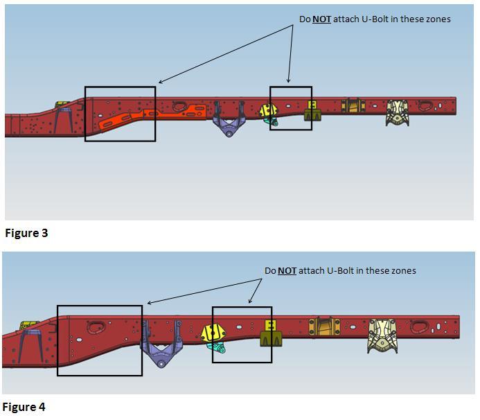
10 Longitudinal Rail Spacer Frame Figure 2 Multiple attachments between the up-fit body and frame are required to keep the up fit snug against the longitudinal spacer. Attaching the applied body at only the front and rear ends is not sufficient. A good common mounting practice is to attach every 18 inches where possible. If U-bolts are used as an attachment, at least one shear mount per side and multiple U-bolt attachments per side (depending on wheelbase) are required to keep the spacer and up-fit secure against the frame rail. If using U-Bolts for attaching the sub-frame to the vehicle frame, vertical spacer blocks must be installed between the upper and lower flange of the rail at the point of attachment in order to prevent damage to the flanges. Vertical spacer blocks must account for adequate clearance from all electrical or fluid lines installed along the rail. When using wood as a spacer, always ensure there is adequate distance or protection from exhaust system heat. Note: do not use U bolts on any other location other than flat sections of the rail. If the rail is changing depth in the area necessary to attach, always use a shear plate. Critical zones to avoid U-bolt attachment are show in Figure 3 & 4.
11

12 Though it is not recommended, where the use of a longitudinal spacer is not practical such as when the gap between the rail and up-fit sub-frame is too large, a minimum of 4 attachment locations per side are required along the rail to assure even distribution of load. An example of suggested attachment locations can be seen in Figure 5. These 8 attachments cannot be located in the areas of the rail outlined in Figure 6. These are the areas of the shock skive out reinforcement which is rearward of the front auxiliary spring pad bracket and forward of the jounce bumper bracket, as well as, the area that has 3 holes forward of the rear spring rear hanger. Efforts to provide longitudinal spacers in areas where clearance is not an issue should still be made.
2016 ProMaster Design Recommendations SYSTEM DESIGN RECOMMENDATIONS FUEL SYSTEMS
 SYSTEM DESIGN RECOMMENDATIONS FUEL SYSTEMS Any modification of fuel tanks, lines, hoses or connectors is the complete responsibility of the second stage manufacturer. The responsibility for determining
2014 Chassis Cab Frame Alteration Recommendations
 Frame Alteration Recommendations The recommendations below are suggestions for the best practices of frame alterations to accommodate specialty upfit components. However the persons modifying the frame
Body Builders Layout Book
 1 MOUNTING INDEX MOUNTING Page General Information 2 E-Series Cutaway E-Series Stripped Chassis 3 4 Super Duty F-Series 5-7 Transit 8-10 2 MOUNTING GENERAL INFORMATION INFORMATION The following recommendations
Special Applications PB 1
 Special Applications PB 1 Contents 1 PICKUP BOX REMOVED RPO ZW9 PROGRAM... 2 Alterations to Complete Vehicles... 2 Vehicle:... 3 Service Parts:... 3 Areas of Modification... 4 CMVSS and FMVSS... 4 Box
Special Applications Pick Up Box Removal PB 1
 Special Applications Pick Up Box Removal PB 1 Contents Alterations to Complete Vehicles... 2 Vehicle:... 3 Service Parts:... 3 Areas of Modification... 4 CMVSS and FMVSS... 4 Pickup Box Removal Fuel Fill
UI BULLETIN # 28b. REAR BUMPER REMOVAL Information is also provided for modifiers who intend only to remove the rear bumper from the All New C/K.
 UI BULLETIN # 28b SUBJECT: Pickup Box Removal MODELS/YEARS AFFECTED: 2001-2012 S/T Pickup Trucks 2001-2006 C/K Pickup Trucks DATE: 1/26/2017 PAGE: 1 of 33 PICKUP BOX REMOVAL PROGRAM The following information
Incomplete Vehicle Document 2014 Model Year NOTE:
 NOTE: YOU CAN PRODUCE YOUR OWN LEGITIMATE INCOMPLETE VEHICLE DOCUMENT BY PRINTING THIS DOCUMENT AND THEN TAKING A PHOTO OF THE CERT. LABEL ON THE DRIVERS DOOR OPENING. 55351115AZ CHRYSLER GROUP LLC 800
TOYOTA TUNDRA 3 BODY LIFT INSTALLATION INSTRUCTIONS 2014 KIT# 5643
 3651 N Highway 89 Chino Valley, AZ 86323 (928) 636-7080 www.p-a-g.net TOYOTA TUNDRA 3 BODY LIFT INSTALLATION INSTRUCTIONS 2014 KIT# 5643 Installation of a Performance Automotive Group body lift kit will
SVE BULLETIN F-Series Super Duty with Aftermarket Auxiliary AC System Control
 Q-255 2017 F-Series Super Duty with Aftermarket Auxiliary AC System Control Models Affected 2017 F-350, F-450, F-550 Chassis Cab applications with the addition of auxiliary air conditioning systems beginning
95-98 CHEVY TRUCK INSTALLATION INSTRUCTIONS KIT #112 #113
 This body lift kit should only be installed on vehicles that are in good working condition. Before the installation begins, the vehicle should be thoroughly inspected for evidence of corrosion or deformation
Super Duty Front Air Bag Installation Instructions
 2005-2010 Super Duty Front Air Bag Installation Instructions Congratulations! You have just purchased the best engineered, highest quality front air suspension kit available on the market for your 2005-2010
TITAN Fuel Tanks. INSTALLATION INSTRUCTIONS G e n e r a t i o n V. Extended Capacity Replacement Tank for Diesel Chevrolet / GMC Trucks
 Important: Please read these instructions carefully and completely before starting the installation. TITAN Fuel Tanks INSTALLATION INSTRUCTIONS G e n e r a t i o n V Extended Capacity Replacement Tank
CHEVY/GMC /2-TON PICKUP 3 BODY LIFT INSTALLATION INSTRUCTIONS 2006 KIT# PA10163 MANUAL TRANSMISSION VEHICLES REQUIRE KIT# PA4701
 3651 N Highway 89 Chino Valley, AZ 86323 (928) 636-7080 www.p-a-g.net CHEVY/GMC 1500 1/2-TON PICKUP 3 BODY LIFT INSTALLATION INSTRUCTIONS 2006 KIT# PA10163 MANUAL TRANSMISSION VEHICLES REQUIRE KIT# PA4701
PICKUP BOX REMOVAL/ALTERATIONS DESIGN RECOMMENDATIONS
 Page 177 PICKUP BOX PART I Introduction The following information is presented in three parts for vehicle alterers who intend to remove pickup boxes from certain Rangers and Super Duty F-Series pickup
Owner s Manual TC-515 with Reversed Hoist, Sub-Frame, Deck, & Hitch Mount
 Proudly built in the USA Owner s Manual TC-55 with Reversed Hoist, Sub-Frame, Deck, & Hitch Mount TruckCraft Corporation Chambersburg, PA -800-755-87 Copyright c 0 www.truckcraft.com TruckCraft Corporation
PAGE DESCRIPTION REF. NO.
 TABLE OF CONTENTS VC 628 / 5520 / 6620 MANUAL PAGE DESCRIPTION REF. NO. 1 READ THIS FIRST... 416756 2 IMPORTANT WARNING... 416086 3 WARNING AND CAUTION DECAL LOCATIONS... 416128 4 DECAL DRAWINGS & LIST...
Rear bumper cannot be used for towing after installation of the rear bumper relocation brackets.
 921RC7030 GM 88-98 4WD 1500 P/U 3 Body Lift Thank you for choosing Rough Country for all your suspension needs. *RC703BAG2* RC703BAG2 Rough Country recommends a certified technician install this kit. Attempts
R4TECH PRODUCT SAFETY NOTICE
 R4TECH PRODUCT SAFETY NOTICE Congratulations. This vehicle has been equipped with an R4Tech suspension system that provides the ride quality of a full-air suspension with the ease of installation of a
Please read these instructions completely before proceeding with installation. Read all maintenance guidelines on page 7 before operating the vehicle.
 MN-643 (02511) ECR 5461 Kit No. 39205 Please read these instructions completely before proceeding with installation Item P/N Description Quantity A 26391 Driver-Side Beam Assembly 1 B 26414 Passenger-Side
DODGE DAKOTA 3 BODY LIFT INSTALLATION INSTRUCTIONS KIT # 60153
 DODGE DAKOTA 3 BODY LIFT INSTALLATION INSTRUCTIONS 2003-04 KIT # 60153 Installation of a Performance Automotive Group body lift kit will change the vehicle s center of gravity and handling characteristics
1501 Industrial Way N., Toms River, NJ Fax: PACKING LIST MUSTANG LONG TUBE HEADERS (M30000)
") 2/18/04 1501 Industrial Way N., Toms River, NJ 08755 732-349-2109 Fax:732-244-0867 ADVANCED - Installation requires professional-type tools and advanced automotive-service skills. If you lack experience
2/18/04 1501 Industrial Way N., Toms River, NJ 08755 732-349-2109 Fax:732-244-0867 ADVANCED - Installation requires professional-type tools and advanced automotive-service skills. If you lack experience
Important: Please read these instructions carefully and completely before starting the installation. TITAN Fuel Tanks INSTALLATION GUIDE
 TITAN pt. no.: 03 0000 0128 Important: Please read these instructions carefully and completely before starting the installation. TITAN Fuel Tanks INSTALLATION GUIDE 30 Gallon* Spare Tire Auxiliary Fuel
WARNING: HARDWARE PACK (A ) DO NOT INSTALL if the truck has been lifted and the stock jounce bumper spacers are not on the vehicle.
 DO NOT INSTALL if the truck has been lifted and the stock jounce bumper spacers are not on the vehicle.") DO NOT INSTALL if the truck has been lifted and the stock jounce bumper spacers are not on the vehicle. 2550 WARNING: Do not inflate this assembly when it is unrestricted. The assembly must be restricted
DO NOT INSTALL if the truck has been lifted and the stock jounce bumper spacers are not on the vehicle. 2550 WARNING: Do not inflate this assembly when it is unrestricted. The assembly must be restricted
SVE BULLETIN. QVM Bulletin: Q-186 Date: 29 March, F-Series Super Duty Chassis Cab 6.7L Diesel Urea Tank Relocation Kit
 Q-186 SVE BULLETIN SPECIAL ENGINEERING BODY BUILDERS ADVISORY SERVICE E-Mail via website: www.fleet.ford.com/truckbbas (click "Contact Us") Toll-free: (877) 840-4338 QVM Bulletin: Q-186 Date: 29 March,
NISSAN TITAN 3 BODY LIFT INSTALLATION INSTRUCTIONS KIT # 40053
 3651 N Highway 89 Chino Valley, AZ 86323 (928) 636-7080 NISSAN TITAN 3 BODY LIFT INSTALLATION INSTRUCTIONS 2004-2009 KIT # 40053 Installation of a Performance Automotive Group body lift kit will change
Kit INSTALLATION GUIDE. Honda Odyssey, Honda Pilot, & Acura MDX
 Kit 60815 Honda Odyssey, Honda Pilot, & Acura MDX Cover illustration may not depict actual kit. MN-692 (021202) ECR 7276 INSTALLATION GUIDE For maximum effectiveness and safety, please read these instructions
FAX
 INSTALLATION INSTRUCTIONS 6090 Air Suspension Kit (pat. pending) 1999-2006 Tahoe, Suburban, Avalanche, Yukon Thank you for purchasing a quality Hellwig Product. PLEASE READ THIS INSTRUCTION SHEET COMPLETELY
JK V8 HEMI BUILDER KIT Overview
 JK V8 HEMI BUILDER KIT Overview Installation Guide 5.7L & 6.1L HEMI 2007-2008 JK - SWB, LWB Page 1 of 1 Congratulations on purchasing your AEV HEMI JK Installation kit. These instructions have been written
650 Series Cargo Van Lift Mounting Instructions Ford Transit (Standard Roof) 2015-Present
 2015-Present") TOMMY GATE OWNER'S / OPERATOR'S MANUAL 650 Series 650 LB Capacity 650 Series Cargo Van Lift Mounting Instructions Ford Transit (Standard Roof) 2015-Present Installing the Base Plate 1. Examine the interior
TOMMY GATE OWNER'S / OPERATOR'S MANUAL 650 Series 650 LB Capacity 650 Series Cargo Van Lift Mounting Instructions Ford Transit (Standard Roof) 2015-Present Installing the Base Plate 1. Examine the interior
INSTALLATION INSTRUCTIONS DODGE DAKOTA 2 KIT # 682 (2WD), 692 (4WD) 3 KIT # 683 (2WD), 693 (4WD)
, 692 (4WD) 3 KIT # 683 (2WD), 693 (4WD)") INSTALLATION INSTRUCTIONS 1997-1999 DODGE DAKOTA 2 KIT # 682 (2WD), 692 (4WD) 3 KIT # 683 (2WD), 693 (4WD) Installation of a Performance Accessories body lift kit will change the vehicle s center of gravity
INSTALLATION INSTRUCTIONS 1997-1999 DODGE DAKOTA 2 KIT # 682 (2WD), 692 (4WD) 3 KIT # 683 (2WD), 693 (4WD) Installation of a Performance Accessories body lift kit will change the vehicle s center of gravity
2004 S/T SMALL TRUCK AGE P
 2004 S/T SMALL TRUCK i BODY BUILDERS INSTRUCTIONS... 1 Section 0 General Instructions... 1 Section 1 Body... 2 Air Conditioning... 2 Section 2 Frame... 3 Flanges... 3 Holes... 3 Welding... 3 Alterations...
DODGE DAKOTA 3 KIT INSTALLATION INSTRUCTIONS KIT# 60043
 DODGE DAKOTA 3 KIT INSTALLATION INSTRUCTIONS 2000-2002 KIT# 60043 Installation of a Performance Automotive Group body lift kit will change the vehicle s center of gravity and handling characteristics both
Parts List & Mounting Instructions Kubota F2260, F2560, F3060
 JODALE PERRY Parts List & Mounting Instructions Kubota F2260, F2560, F3060 JDP BUILT FOR LIFE BRACKETS, SHIELDS, ETC.: Qty Description 1 Front bracket 6 Front bracket spacers 1 Fuel spout (w/cap) 1 4 x
JEEP WRANGLER INSTALLATION INSTRUCTIONS KIT SUM
 1986-1995 JEEP WRANGLER INSTALLATION INSTRUCTIONS KIT SUM-7893300 Installation of a body lift will change the center of gravity and the handling characteristics of the vehicle. Because of the higher center
CHEVY AVALANCHE 1/2-TON ONLY 3 BODY LIFT KIT INSTALLATION INSTRUCTIONS KIT# 10173
 3651 N Highway 89 Chino Valley, AZ 86323 (928) 636-7080 www.p-a-g.net CHEVY AVALANCHE 1/2-TON ONLY 3 BODY LIFT KIT INSTALLATION INSTRUCTIONS 2003-2005 KIT# 10173 Installation of a Performance Automotive
DODGE DAKOTA (AUTO TRANS. ONLY) 3 BODY LIFT INSTALLATION INSTRUCTIONS KIT# 60163
 3 BODY LIFT INSTALLATION INSTRUCTIONS KIT# 60163") 3651 N Highway 89 Chino Valley, AZ 86323 (928) 636-7080 www.p-a-g.net DODGE DAKOTA (AUTO TRANS. ONLY) 3 BODY LIFT INSTALLATION INSTRUCTIONS 2005-2006 KIT# 60163 Many states and municipalities have laws
3651 N Highway 89 Chino Valley, AZ 86323 (928) 636-7080 www.p-a-g.net DODGE DAKOTA (AUTO TRANS. ONLY) 3 BODY LIFT INSTALLATION INSTRUCTIONS 2005-2006 KIT# 60163 Many states and municipalities have laws
DUMP BODY SPREADERS INSTALLATION INSTRUCTIONS
 DUMP BODY SPREADERS INSTALLATION INSTRUCTIONS (Includes PS350 & PS400) EFFECTIVE 09/2011 Revision A 1330 76TH AVE SW CEDAR RAPIDS, IA 52404-7052 PHONE (319) 363-8281 FAX (319) 286-3350 www.highwayequipment.com
BD TrackMaster S D o d g e H P C R Installation Instructions
 7 July 2016 PN#1045701, 1045702, 1045704 Dodge 6.7L TMS400 (I-00361) 1 BD TrackMaster S400 2008-2012 D o d g e H P C R Installation Instructions 1045701 2008-2009 Dodge 6.7L TMS400 1045702 2010-2012 Dodge
TABLE OF CONTENTS VC 620 W/ LINKAGE BODY PROP MANUAL TABLE OF CONTENTS VC 620 W/ LINK. PROP
 TABLE OF CONTENTS VC 620 W/ LINKAGE BODY PROP MANUAL PAGE DESCRIPTION REF. NO. 1 READ THIS FIRST... 416733 2 IMPORTANT WARNING...416086 3 WARNING AND CAUTION DECAL LOCATIONS... 416850 4 DECAL DRAWINGS
2015+ F-150 Active Exhaust Kit Installation Instructions P/N: (1117-5E292LITE)
") 2015+ F-150 Active Exhaust Kit Installation Instructions P/N: 422104 (1117-5E292LITE) 39555 Schoolcraft Rd, Plymouth MI, 48170 800.59.ROUSH 2015+ Ford F-150 Active Exhaust Kit Installation Instructions
2015+ F-150 Active Exhaust Kit Installation Instructions P/N: 422104 (1117-5E292LITE) 39555 Schoolcraft Rd, Plymouth MI, 48170 800.59.ROUSH 2015+ Ford F-150 Active Exhaust Kit Installation Instructions
650 Series Cargo Van Lift Mounting Instructions Fullsize Ford 1992-Present
 TOMMY GATE OWNER'S / OPERATOR'S MANUAL 650 Series 650 LB Capacity 650 Series Cargo Van Lift Mounting Instructions Fullsize Ford 1992-Present Installing the Base Plate 1. Examine the interior and exterior
HP10033 KIT. * See application guide for proper fitment.
 HP10033 KIT * See application guide for proper fitment. Use the most advanced air springs on the market to eliminate your vehicle s sag, sway and bottoming out. Pacbrake air suspension levels your truck
READ INSTRUCTIONS COMPLETELY BEFORE BEGINNING INSTALLATION
 INSTALLATION INSTRUCTIONS Hot Fox In-Tank Fuel Warmer READ INSTRUCTIONS COMPLETELY BEFORE BEGINNING INSTALLATION Models covered by these instructions include: HFG 0-0 HFG 0- SHFT--0- SHH--0 TWHF 0- HFG
CHEVY / GMC BLAZER / YUKON SUBURBAN BODY LIFT INSTALLATION INSTRUCTIONS KIT # KIT #10023
 3651 N Highway 89 Chino Valley, AZ 86323 (928) 636-7080 CHEVY / GMC BLAZER / YUKON SUBURBAN BODY LIFT INSTALLATION INSTRUCTIONS 1992-1994 2 KIT #10022 1992-1994 3 KIT #10023 Before you install this kit,
CHEVY COLORADO GMC CANYON BODY LIFT INSTALLATION INSTRUCTIONS KIT # 10153
 CHEVY COLORADO GMC CANYON BODY LIFT INSTALLATION INSTRUCTIONS 2004-2005 3 KIT # 10153 Installation of a Performance Automotive Group body lift kit will change the vehicle s center of gravity and handling
INSTALLATION INSTRUCTIONS
 2807 INSTALLATION INSTRUCTIONS SECTION - AIR SPRING SECTION 2 - AIR ACCESSORY -6 ! IMPORTANT PLEASE DON T HURT YOURSELF, YOUR KIT OR YOUR VEHICLE. TAKE A MINUTE TO READ THIS IMPORTANT INFORMATION. This
S/T TRUCK BODY BUILDERS INSTRUCTIONS. Section 1 Body. Section 0 General Instructions PAGE
 S/T TRUCK PAGE 1 BODY BUILDERS INSTRUCTIONS The Incomplete Vehicle Document (IVD) is supplied with each incomplete vehicle, and provides information that should be used by intermediate and final stage
3651 N Highway 89 Chino Valley, AZ (928)
") 3651 N Highway 89 Chino Valley, AZ 86323 (928) 636-7080 www.p-a-g.net CHEVY/GMC 1500 P/U GAS ENG. NEW BODY STYLE (INCLUDING AUTOMATIC TRANS W/ ELECTRONIC 4WD) 3 BODY LIFT KIT INSTALLATION INSTRUCTIONS
3651 N Highway 89 Chino Valley, AZ 86323 (928) 636-7080 www.p-a-g.net CHEVY/GMC 1500 P/U GAS ENG. NEW BODY STYLE (INCLUDING AUTOMATIC TRANS W/ ELECTRONIC 4WD) 3 BODY LIFT KIT INSTALLATION INSTRUCTIONS
TOYOTA TUNDRA 2 & 4WD 3 BODY LIFT KIT INSTALLATION INSTRUCTIONS 2006 KIT# 5623
 3651 N Highway 89 Chino Valley, AZ 86323 (928) 636-7080 www.p-a-g.net TOYOTA TUNDRA 2 & 4WD 3 BODY LIFT KIT INSTALLATION INSTRUCTIONS 2006 KIT# 5623 Installation of a Performance Automotive Group body
3651 N Highway 89 Chino Valley, AZ (928)
") 3651 N Highway 89 Chino Valley, AZ 86323 (928) 636-7080 CHEVY TRUCK 2 & 3 BODY LIFT KIT INSTALLATION INSTRUCTIONS 1973-1987 STEPSIDE PICKUP KIT# 512 (2 ), 513 (3 ) 1973-1987 FLEETSIDE PICKUP KIT# 522 (2
3651 N Highway 89 Chino Valley, AZ 86323 (928) 636-7080 CHEVY TRUCK 2 & 3 BODY LIFT KIT INSTALLATION INSTRUCTIONS 1973-1987 STEPSIDE PICKUP KIT# 512 (2 ), 513 (3 ) 1973-1987 FLEETSIDE PICKUP KIT# 522 (2
Kit No Please read these instructions completely before proceeding with installation. Parts List G J I K L H CC FF DD MN-505 (01201) NPR 3733
 NPR 3733") Kit No. 57154 MN-505 (01201) NPR 3733 Please read these instructions completely before proceeding with installation Parts List by www.airliftcompany.com Item P/N Description Quantity A 58407 Air Spring
Kit No. 57154 MN-505 (01201) NPR 3733 Please read these instructions completely before proceeding with installation Parts List by www.airliftcompany.com Item P/N Description Quantity A 58407 Air Spring
GM HD Heavy Duty 4 Link Tow Kit Installation Instructions
 2001-2010 GM HD Heavy Duty 4 Link Tow Kit Installation Instructions Congratulations! You have just purchased the best engineered, highest quality air suspension kit available on the market for your 2001-2010
Jacobsen 600, Ransomes 700 Series
 Jacobsen 600, Ransomes 700 Series Soft Side/ROPS Parts List & Mounting Instructions Jodale Perry Printed: 2001/11 Standard Parts List Qty Description Photo L&R Rear Mounting Brackets L&R Front Mounting
INSTRUCTIONS, RAM DUAL REAR WHEEL TRUCKS INSTALLATION KIT (C2 LIFTGATES)
") LIFT CORPORATION Sht. 1 of 23 DSG# M-15-25 Rev. B Date: 05/31/2017 INSTRUCTIONS, RAM DUAL REAR WHEEL TRUCKS INSTALLATION KIT (C2 LIFTGATES) RAM 3500 DUAL REAR WHEEL PICKUP TRUCKS, 2013 TO 2015 KIT P/N
LIFT CORPORATION Sht. 1 of 23 DSG# M-15-25 Rev. B Date: 05/31/2017 INSTRUCTIONS, RAM DUAL REAR WHEEL TRUCKS INSTALLATION KIT (C2 LIFTGATES) RAM 3500 DUAL REAR WHEEL PICKUP TRUCKS, 2013 TO 2015 KIT P/N
GT-R Alpha 10/12 Turbo Kit
 GT-R Alpha 10/12 Turbo Kit Instructions V6 The goal of AMS is to provide the highest quality, best performing products available. By utilizing research and development, and rigorous testing programs AMS
Rear bumper cannot be used for towing after installation of the rear bumper relocation brackets.
 921RC7020 *RC702BAG2* RC702BAG2 GM 07-13 4WD 1500 P/U 3 Body Lift Thank you for choosing Rough Country for all your suspension needs. Rough Country recommends a certified technician install this kit. Attempts
4 December 2017 PN# , , Dodge 6.7L Rumble B SXE (I-00400) 1. BD Rumble B SXE. D o d g e 6. 7 L H P C R Installation Instructions
 1. BD Rumble B SXE. D o d g e 6. 7 L H P C R Installation Instructions") 4 December 2017 PN#1045705, 1045706, 1045708 Dodge 6.7L Rumble B SXE (I-00400) 1 DOWNLOAD ENHANCED INSTALL MANUALS AT dieselperformance.com BD Rumble B SXE D o d g e 6. 7 L H P C R Installation Instructions
4 December 2017 PN#1045705, 1045706, 1045708 Dodge 6.7L Rumble B SXE (I-00400) 1 DOWNLOAD ENHANCED INSTALL MANUALS AT dieselperformance.com BD Rumble B SXE D o d g e 6. 7 L H P C R Installation Instructions
P Original Series Cargo Van Lift Mounting Instructions Fullsize Ford Van present. Preparing the Gate
 Fullsize Ford Van- 1992-present Preparing the Gate 1. Remove the mounting hardware which is banded to the liftgate. 2. Verify mounting kit (Figure 1 and Table 1). S-400-40 STRAP VAN MOUNTING EAR BENT BRACKET
»Product» Safety Warning
 #F9383 Installation Instructions 2004-2005 F-150 5dr/5.4L 3" Body Lift without Factory Receiver Read and understand all instructions and warnings prior to installation of product and operation of vehicle.
DODGE RAM 2500/3500 (4WD) *HEMI ENGINE ONLY* (INCLUDING MEGA CAB) (EXCLUDING POWER WAGON) 3 BODY LIFT INSTALLATION INSTRUCTIONS KIT# 60223
 *HEMI ENGINE ONLY* (INCLUDING MEGA CAB) (EXCLUDING POWER WAGON) 3 BODY LIFT INSTALLATION INSTRUCTIONS KIT# 60223") 3651 N Highway 89 Chino Valley, AZ 86323 (928) 636-7080 www.p-a-g.net DODGE RAM 2500/3500 (4WD) *HEMI ENGINE ONLY* (INCLUDING MEGA CAB) (EXCLUDING POWER WAGON) 3 BODY LIFT INSTALLATION INSTRUCTIONS 2010-2012
3651 N Highway 89 Chino Valley, AZ 86323 (928) 636-7080 www.p-a-g.net DODGE RAM 2500/3500 (4WD) *HEMI ENGINE ONLY* (INCLUDING MEGA CAB) (EXCLUDING POWER WAGON) 3 BODY LIFT INSTALLATION INSTRUCTIONS 2010-2012
CHEVY TRUCK INSTALLATION INSTRUCTIONS KIT SUM
 1988-1994 CHEVY TRUCK INSTALLATION INSTRUCTIONS KIT SUM-7810013 Installation of a body lift will change the center of gravity and the handling characteristics of the vehicle. Because of the higher center
TABLE OF CONTENTS VC 620 / 628 / 5520 / 6620 / 6628 MANUAL TABLE OF CONTENTS F VC VC 6628 PAGE DESCRIPTION REF. NO.
 TABLE OF CONTENTS VC 620 / 628 / 5520 / 6620 / 6628 MANUAL PAGE DESCRIPTION REF. NO. 1 READ THIS FIRST... 416733 2 IMPORTANT WARNING... 416086 3 WARNING AND CAUTION DECALS... 416128 4 VC 620 CAPACITIES...
I. Assembling the Air Spring
 B F H G D FRONT I Assembling the Air Spring 1 Install 90 degree air swivel fitting (D) to the top of the bellow This fitting is precoated with sealant Using an open-end wrench, tighten 1 and 1 /2 turns
DODGE / RAM 1500 *** DO NOT EXCEED VEHICLE MANUFACTURER'S RECOMENDED TOWING CAPACITY ***
 6444 DODGE / RAM 500 6/8/207 OF 5 *** DO NOT EXCEED MANUFACTURER'S RECOMENDED TOWING CAPACITY *** ITEM QTY PART NUMBER 0 /2-3 x 2" 2 4 /2-3 x 3/4, GR8 3 4 CM-SP2 4 2 CM-SP6 5 4 HFN 23, GR8 6 2 CM-SP4 7
INSTALLATION INSTRUCTIONS MOUNTING KIT FOR ELITE SERIES
 INSTALLATION INSTRUCTIONS MOUNTING KIT FOR ELITE SERIES DO NOT EXCEED VEHICLE MANUFACTURER S RATING FOR 5th WHEEL TOWING OR MAXIMUM GROSS TRAILER WEIGHT OF 18,000lb. / 8160kg. DEALER/INSTALLER: (1) Provide
BRAKES. Air Brake Modifications DURASTAR SERIES BODY BUILDER BRAKES FEBRUARY 2015 PAGE 159 ALL MODELS - AIR BRAKE MODIFICATIONS
 BRAKES ALL MODELS Air Brake Modifications Certification Procedures For DOT FMVSS-121 The Federal Department of Transportation's Motor Vehicle Safety Standard 121 required that virtually all trucks equipped
and Original Series Pickup Lift Mounting Instructions Fullsize Nissan Titan Trucks present T-420 BOLT-ON GUSSET PART#5257
 and Original Series Pickup Lift Mounting Instructions Fullsize Nissan Titan Trucks- 2004-present Preparing the Gate 1. Remove the mounting hardware which is banded to the liftgate. 2. Verify mounting bracket
FRAME AND BUMPERS 13-1 FRAME AND BUMPERS CONTENTS
 J FRAME AND BUMPERS 13-1 FRAME AND BUMPERS CONTENTS BUMPERS... 5 BUMPERS... 16 FRAME... 1 FRAME... 10 FRAME INDEX Frame Dimensions... 1 Front Skid Plate... 1 Fuel Filler Hose Splash Shield XJ Vehicles...
PRODUCT USE INFORMATION
 9RC61000 Jeep YJ Body Lift Thank you for choosing Rough Country for all your suspension needs. This body lift fits both manual and Automatic equipped vehicles!!! Refer to last page of this Instruction
Kit No Please read these instructions completely before proceeding with installation. Air Spring Kit Parts List. Attaching Hardware
 Kit No. 57340 MN-431 (02409) NPR 4796 Please read these instructions completely before proceeding with installation by www.airliftcompany.com Air Spring Kit Parts List A B1 B2 Item Description Quantity
DODGE RAM 2500/3500 2WD *DIESEL ENGINE ONLY* (INCLUDING MEGA CAB) 3 BODY LIFT INSTALLATION INSTRUCTIONS KIT# PA60313
 3 BODY LIFT INSTALLATION INSTRUCTIONS KIT# PA60313") DO NOT combine suspension, body, or other lift devices. Use of vehicle with combined lifts may result in unsafe and/or unexpected handling characteristics. DODGE RAM 2500/3500 2WD *DIESEL ENGINE ONLY*
DO NOT combine suspension, body, or other lift devices. Use of vehicle with combined lifts may result in unsafe and/or unexpected handling characteristics. DODGE RAM 2500/3500 2WD *DIESEL ENGINE ONLY*
FAX
 INSTALLATION INSTRUCTIONS 6299 Air Suspension Kit (pat. pending) 2009+ Dodge 1500 Pickup with Rear Coil Springs Thank you for purchasing a quality Hellwig Product. PLEASE READ THIS INSTRUCTION SHEET COMPLETELY
INSTALLATION INSTRUCTIONS 97 FORD EXPEDITION
 INSTALLATION INSTRUCTIONS 97 FORD EXPEDITION 1. Read the instructions completely and carefully before you begin. Check the kit for proper contents (refer to the part s list and the picture diagrams). Before
Jacobsen 600 Series Ransomes 700 Series
 Jacobsen 600 Series Ransomes 700 Series Parts List & Mounting Instructions Jodale Perry Printed: 2004/01 Standard Parts List Qty Description Photo L&R Rear Mounting Brackets L&R Front Mounting Brackets
Cooling System. Table of Contents
 Sub-Headings Safety 2 s 2 Cautions 2 Notes 2 Introduction 2 General Specifications 2 Engine 2 Coolant 2 Routine Maintenance 2 Hose Connections 4 Radiator, Charge Air and Heater Cores 4 Cooling System Leaks
Owner smanual. Banks Techni-Cooler System Dodge 6.7L Cummins (24-valve) ISB Pickup Trucks (2500/3500) USE WITH SYSTEM P/N 25987
 ISB Pickup Trucks (2500/3500) USE WITH SYSTEM P/N 25987") Owner smanual with Installation Instructions Banks Techni-Cooler System 2013-16 Dodge 6.7L Cummins (24-valve) ISB Pickup Trucks (2500/3500) USE WITH SYSTEM P/N 25987 Gale Banks Engineering 546 Duggan Avenue
Owner smanual with Installation Instructions Banks Techni-Cooler System 2013-16 Dodge 6.7L Cummins (24-valve) ISB Pickup Trucks (2500/3500) USE WITH SYSTEM P/N 25987 Gale Banks Engineering 546 Duggan Avenue
FORD RANGER/SPLASH MAZDA B-SERIES (2&4WD, STANDARD & EXT. CAB) 3 BODY LIFT KIT INSTALLATION INSTRUCTIONS KIT# 853
 3 BODY LIFT KIT INSTALLATION INSTRUCTIONS KIT# 853") 3651 N Highway 89 Chino Valley, AZ 86323 (928) 636-7080 www.p-a-g.net FORD RANGER/SPLASH MAZDA B-SERIES (2&4WD, STANDARD & EXT. CAB) 3 BODY LIFT KIT INSTALLATION INSTRUCTIONS 1995-1997 KIT# 853 Installation
3651 N Highway 89 Chino Valley, AZ 86323 (928) 636-7080 www.p-a-g.net FORD RANGER/SPLASH MAZDA B-SERIES (2&4WD, STANDARD & EXT. CAB) 3 BODY LIFT KIT INSTALLATION INSTRUCTIONS 1995-1997 KIT# 853 Installation
Tools Needed. I. Getting Started
 5 /16 ", 7 /16 ", 9 /16 " and 19mm open-end or box wrenches Crescent Wrench Ratchet with 9 /16 " and 1 /2 " deep well sockets 3 /8 " and 5 /16 " drill bits (very sharp) Heavy Duty Drill Torque Wrench Tools
Installation Instructions
 Installation Instructions DODGE RAM (1/2 TON AND 3/4 TON) 2002 2008 1500 PICK UP TRUCK 2003 2012 2500 PICK UP TRUCK (Except Megacab) Part Numbers: 50040 Parts List Qty A 1 B 1 C 2 D 2 E 2 F 2 Description
2001 CHEVY SILVERADO HD INSTALLATION INSTRUCTIONS - KIT #183
 WARNING This body lift kit should only be installed on vehicles in good working condition. Before installation, the vehicle should be thoroughly inspected for evidence of corrosion or deformation of the
EXHAUST SYSTEM AND INTAKE MANIFOLD
 J EXHAUST SYSTEM AND INTAKE MANIFOLD 11-1 EXHAUST SYSTEM AND INTAKE MANIFOLD CONTENTS page EXHAUST SYSTEM... 1 EXHAUST SYSTEM DIAGNOSIS... 2 page SERVICE PROCEDURES... 3 TORQUE SPECIFICATIONS... 10 EXHAUST
Installation Instructions
 Equipment Required: Installation Instructions Fastener Kit: F Wrenches: 8mm, 13mm, 3/4, 15/16 Drill Bits: 1/4 Other Tools: Drill, Reciprocating Saw, File WARNING: Under no circumstances do we recommend
2-row and All-row systems included.
 Ag Leader Technology Cotton Picker Installation Installation Instructions for John Deere cotton picker models: 2-row and All-row systems included. IMPORTANT: Ensure the model numbers shown above correspond
Fig & MOUNTING RAIL INSTALLATION KIT
 16100 & 16200 MOUNTING RAIL INSTALLATION KIT 09/28/06 CUSTOM MOUNTING BRACKETS REQUIRED ON SOME INSTALLATIONS DEALER/INSTALLER: 1) Provide this manual to end user. 2) Physically demonstrate procedure in
EXHAUST SYSTEM AND INTAKE MANIFOLD
 EXHAUST SYSTEM AND INTAKE MANIFOLD 11-1 EXHAUST SYSTEM AND INTAKE MANIFOLD CONTENTS page GENERAL INFORMATION... 1 SERVICE PROCEDURES... 4 page TORQUE SPECIFICATION... 13 EXHAUST SYSTEMS The exhaust systems
WARNING DO NOT EXCEED THE MANUFACTURER S RECOMMENDED GROSS VEHICLE WEIGHT RATING (GVWR).
.") WARNING DO NOT EXCEED THE MANUFACTURER S RECOMMENDED GROSS VEHICLE WEIGHT RATING (GVWR). As in any suspension installation, it is the installer s responsibility to assure a correct installation. The installer
WARNING DO NOT EXCEED THE MANUFACTURER S RECOMMENDED GROSS VEHICLE WEIGHT RATING (GVWR). As in any suspension installation, it is the installer s responsibility to assure a correct installation. The installer
INSTALLATION INSTRUCTIONS
 28 INSTALLATION INSTRUCTIONS SECTION - AIR SPRING SECTION 2 - AIR ACCESSORY 2-5 ! IMPORTANT PLEASE DON T HURT YOURSELF, YOUR KIT OR YOUR VEHICLE. TAKE A MINUTE TO READ THIS IMPORTANT INFORMATION. This
1501 Industrial Way N., Toms River, NJ Fax: PACKING LIST MUSTANG GT LONG TUBE HEADERS (M30000)
") ADVANCED - Installation requires professional-type tools and advanced automotive-service skills. If you lack experience with internal engine modifications, an Advanced installation is probably beyond your
ADVANCED - Installation requires professional-type tools and advanced automotive-service skills. If you lack experience with internal engine modifications, an Advanced installation is probably beyond your
HP10207 KIT. Ram WD*
 HP10207 KIT Ram 1500 4WD* (For 2WD call customer service 800.663.0096 for assistance) * See application guide for proper fitment. Use the most advanced air springs on the market to eliminate your vehicle
Dodge Ram 2500/3500 Tow Kit Installation Instructions
 2003-2010 Dodge Ram 2500/3500 Tow Kit Installation Instructions Congratulations! You have just purchased the best engineered, highest quality air suspension kit available on the market for your 2003-2010
TAKE TIME TO READ THE INSTALLATION PROCEDURES BEFORE STARTING
 INSTALLATION INSTRUCTIONS for TTi 318 POLY Header Part No : TTI318C TAKE TIME TO READ THE INSTALLATION PROCEDURES BEFORE STARTING WARNING!!! We strongly suggest that you use an old set of headers or a
INSTRUCTION, DODGE TRUCKS INSTALLATION KIT (C2 LIFTGATES)
") LIFT CORPORATION Sht. 1 of 23 DSG# M-14-25 Rev. B Date: 05/16/17 INSTRUCTION, DODGE TRUCKS INSTALLATION KIT (C2 LIFTGATES) DODGE 1500 PICKUPS, 2002 TO 2016 DODGE 2500 PICKUPS, 2003 TO 2016 KIT P/N 289492-01
LIFT CORPORATION Sht. 1 of 23 DSG# M-14-25 Rev. B Date: 05/16/17 INSTRUCTION, DODGE TRUCKS INSTALLATION KIT (C2 LIFTGATES) DODGE 1500 PICKUPS, 2002 TO 2016 DODGE 2500 PICKUPS, 2003 TO 2016 KIT P/N 289492-01
TruckCraft Corporation Rev. 1/28/2016 I Table of Contents
 TruckCraft Corporation Rev. 1/28/2016 I5-05579 TRUCKCRAFT CORPORATION 5751 Molly Pitcher Hwy. S. Chambersburg, Pa. 17202 Tel. 800.375.3867 Phone 717.375.2900 Fax 717.375.2975 www.truckcraft.com "WHERE
JEEP WRANGLER (TJ), UNLIMITED (TJL), RUBICON MODELS BODY LIFT KIT INSTALLATION INSTRUCTIONS KIT# KIT# 973
, UNLIMITED (TJL), RUBICON MODELS BODY LIFT KIT INSTALLATION INSTRUCTIONS KIT# KIT# 973") JEEP WRANGLER (TJ), UNLIMITED (TJL), RUBICON MODELS BODY LIFT KIT INSTALLATION INSTRUCTIONS 1997-2006 2 KIT# 972 3 KIT# 973 WARNING Installation of a Performance Automotive Group body lift will change
JEEP WRANGLER (TJ), UNLIMITED (TJL), RUBICON MODELS BODY LIFT KIT INSTALLATION INSTRUCTIONS 1997-2006 2 KIT# 972 3 KIT# 973 WARNING Installation of a Performance Automotive Group body lift will change
Instant Chat off the main page of Or simply call our tech team at
 FRONT MOUNT INTERCOOLER 2008-13 STI 2014-04- 08 Thank you for purchasing this PERRIN product for your car! Installation of this product should only be performed by persons experienced with installation
The purpose of this publication is to assist with the installation, maintenance and troubleshooting of the Air Lift 1000 air spring kit.
 Multiple Applications Cover illustration may not depict actual kit. MN-126 (18606) ECR 5682 INSTALLATION GUIDE For maximum effectiveness and safety, please read these instructions completely before proceeding
Owner smanual. Banks Monster Split-Dual Exhaust System Ford Power Stroke 6.0L Turbo-Diesel F250/F350 Trucks. with Installation Instructions
 Owner smanual with Installation Instructions Banks Monster Split-Dual Exhaust System 2003-2007 Ford Power Stroke 6.0L Turbo-Diesel F250/F350 Trucks THIS MANUAL IS FOR USE WITH Systems 47600-47614, 48761,
C-4500 Kit No The Choice of the Professional Installer
 MN-585 (04503) ECR 5047 by C-4500 Kit No. 39023 Please read these instructions completely before proceeding with installation Failure to read these instructions can result in mis-installation Vehicle Requirements...
** DO NOT EXCEED THE RECOMMENDED VEHICLE TOWING WEIGHT RATING ** DODGE RAM 1500
 10/3/2017 DODGE RAM 1500 WARNING!! BRAKE, FUEL, AND ELECTRICAL LINES MAY NEED TO BE LOOSENED OR REPOSITIONED TO PROVIDE CLEARANCE FOR NEW HARDWARE. ON SHORT BED MODELS, CHECK FOR ADEQUATE TURNING CLEARANCE
Vehicle Rear Observation System With Integrated Parking Sensors
 Vehicle Rear Observation System With Integrated Parking Sensors Model: CAMSBAR Installation/User Manual Features: 2.5" LCD Color Display 2 Ultra Sonic Rear Obstacle Sensors On-screen Display Function Automatically