Tools Needed. I. Getting Started
|
|
|
- Garey Porter
- 5 years ago
- Views:
Transcription
1


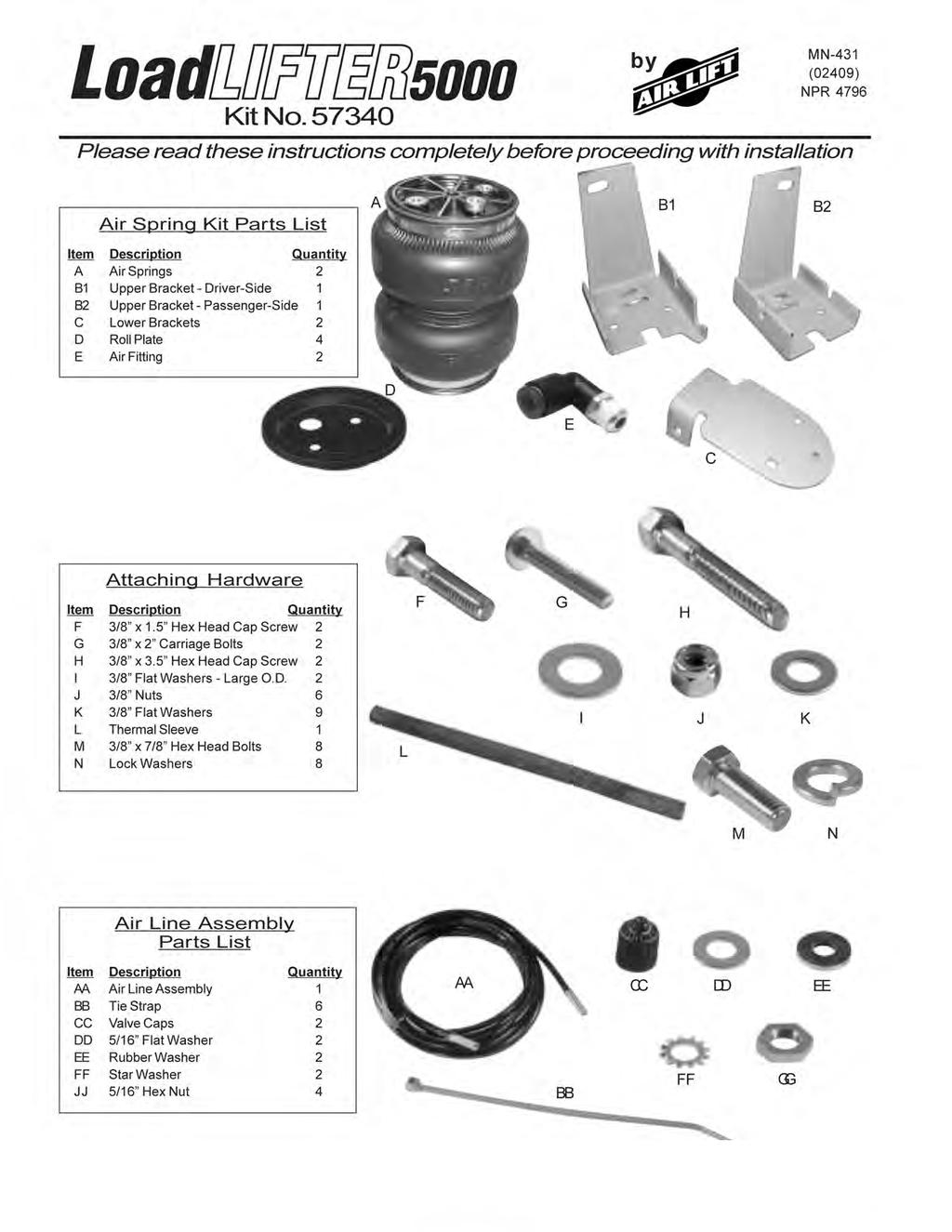
2 5 /16 ", 7 /16 ", 9 /16 " and 19mm open-end or box wrenches Crescent Wrench Ratchet with 9 /16 " and 1 /2 " deep well sockets 3 /8 " and 5 /16 " drill bits (very sharp) Heavy Duty Drill Torque Wrench Tools Needed Hose Cutter, Razor Blade, or Sharp Knife Hoist or Floor Jacks Safety Stands Safety Glasses Air Compressor, or Compressed Air Source Spray Bottle with Dish Soap/Water Solution IMPORTANT: Your vehicle may be equipped with a rear brake proportioning valve Any type of load assist product could affect brake performance We recommend that you check with your dealer before installing this type of product If your vehicle DOES NOT have a rear brake proportioning valve or is equipped with an anti-lock type brake system, installation of a load assist product will have NO EFFECT ON BRAKE SYSTEM PERFORMANCE DANGER: Compressed air can cause injury and damage to the vehicle and parts if it is not handled properly For your safety, do not try to inflate the air sleeves until they have been properly secured to the vehicle I Getting Started 1 Determine the Normal Ride Height The Normal Ride Height is the distance between the bottom edge of the wheel-well and the center of the hub with the vehicle in the as delivered condition In some cases, Normal Ride Height is not perfectly level a Remove unusual loads and examine your vehicle from the side to ensure it is on a level surface b If necessary (in cases where your leaf springs are sagging badly), use a jack to raise the rear end so that the vehicle achieves the original as delivered ride height 2 Measure the distance between the center of the hub and the bottom edge of the wheel well This is the Normal Ride Height Enter the measurement below: NORMAL RIDE HEIGHT: inches

 (Figure 2) 5 On late model Excursions, it may be necessary to splay the tabs on the lower bracket to fit the jounce bumper strike plate properly Do this by putting the bracket in")
 6 Attach the lower bracket (C) to the bottom of the bellows with the tabs down The tabs should be on the same side as the tall edge of the upper bracket (Figure 3a) Use two bolts (M) and")
3 II Assembling the Air Spring Unit 1 Set the roll plate (D) on the top and bottom of the bellows 2 Install the swivel air fitting (E) into the top of the air spring (A) This fitting is pre-coated with sealant Tighten finger-tight plus one and one-half turns with an open-end wrench to seal the fitting NOTE: Use a 7/16 open-end wrench being careful to tighten on the metal hex nut only DO NOT OVERTIGHTEN 3 Insert carriage bolt (G) up through the driver-side upper bracket (B1) (Figure 1) Figure 1 4 Set the bracket and carriage bolt assembly on top of the bellows Attach with two bolts (M) and lock washers (N) (Figure 2) 5 On late model Excursions, it may be necessary to splay the tabs on the lower bracket to fit the jounce bumper strike plate properly Do this by putting the bracket in a vice and bending the tabs slightly with a crescent wrench (Figure 3b) Check fit by sliding lower bracket onto the jounce bumper strike plate It may be necessary to tap into place using a hammer (Figure 7) 6 Attach the lower bracket (C) to the bottom of the bellows with the tabs down The tabs should be on the same side as the tall edge of the upper bracket (Figure 3a) Use two bolts (M) and lock washers (N) Tighten upper and lower brackets to the bellows to 15 ft/lbs Figure 2 Figure 3a Splay the legs of the lower bracket for late model Excursions Figure 3b
 Retain the fasteners for re-attaching the cable bracket IV Lowering the Suspension Figure 4 It will be necessary to")

4 III Removing the Jounce Bumper and Loosening the Brake Cable 1 Remove the jounce bumper The bellows will mount in place of the jounce bumper (Figure 4) 2 The driver-side emergency brake cable must be unbolted Remove the nut and cable bracket, pull loose from the frame (Figure 5) Retain the fasteners for re-attaching the cable bracket IV Lowering the Suspension Figure 4 It will be necessary to lower the suspension to provide clearance to install the air spring unit This can be done by lowering the axle or raising the frame a If the vehicle is raised with an axle contact hoist, place axle stands under the frame and lower the axle as needed b If the vehicle is raised with a frame contact hoist, place axle stands under the axle and raise the frame as needed c If the vehicle was raised with a jack and supported with axle stands on the frame, use a floor jack to lower the axle Figure 5 V Installing the Air Spring 1 The air spring unit assembled in the previous step will install on the driver-side Set the unit in place by inserting the carriage bolt up through the jounce bumper hole (Figure 6) Make sure the emergency brake cable is not caught between the upper bracket and the frame The bracket should fit flush against the outside of the frame The tab on the lower bracket straddles the jounce bumper strike plate Figure 6 2 Push the lower bracket towards the spring so that the tab locks around the strike plate as illustrated in figure 7 Figure 7
 4 Install the previously removed emergency brake cable and nut (Figure 9) Leave loose at this time NOTE: In late model")

 and washer (K) on the carriage bolt inserted through the existing jounce bumper bracket hole (Figure 11) Figure 9 WASHER")
5 3 Insert the existing emergency brake cable bolt through the frame and slot in the upper bracket Install washer (K) over the bolt, and push against the upper bracket (Figure 8) 4 Install the previously removed emergency brake cable and nut (Figure 9) Leave loose at this time NOTE: In late model vehicles, a self-tapping bolt may have been used to attach the emergency brake cable bracket If this is the case for your vehicle, remove the self-tapper and use the supplied bolt, washers, and locknut to re-attach the brake cable bracket and the upper bracket to the frame NOTE: Passenger-side will use bolt (F), washers (I), and nut (J) to attach the upper bracket to the existing hole on the side of the frame (Figure 10) Figure 8 5 Install nut (J) and washer (K) on the carriage bolt inserted through the existing jounce bumper bracket hole (Figure 11) Figure 9 WASHER (I) FRAME BRACKET Figure 10 Figure 11
 Tighten the upper bracket mounting hardware to 15 ft/lbs 8 As in the previous step, move the bottom bracket inward and outward so as to align it with the bellows and the")
6 6 Raise the axle or drop the body to the previously recorded normal ride height 7 Align the upper bracket forward or backward, ensuring the upper and lower brackets are lined up evenly with the bellows (Figures 12 and 13) Tighten the upper bracket mounting hardware to 15 ft/lbs 8 As in the previous step, move the bottom bracket inward and outward so as to align it with the bellows and the upper bracket (Figure 14) Figure 12 Figure 13 Figure 14
 NOTE: Use a C-clamp or welding clamp to assist in")
 and nut (J) and torque to 16 ft/lbs (Figure 16) VI Emergency")
 2 The finished driver-side install is shown")

7 9 Clamp the lower bracket to the strike plate with c-clamps or vice grips Drill a 3/8 hole through the strike plate using the existing holes in the lower bracket as a template (Figure 15) NOTE: Use a C-clamp or welding clamp to assist in keeping the lower bracket as flat to the strike plate as possible before drilling 10 Insert a bolt (H) and washer (K) through the bracket and strike plate Install a washer (K) and nut (J) and torque to 16 ft/lbs (Figure 16) VI Emergency Brake Cable This step is for the driver-side only Figure 15 1 Set the emergency cable into the hook on the driver-side and install a cable tie to keep the cable from chaffing on the bellows (Figure 17) 2 The finished driver-side install is shown in figure 18 VII Install Passenger-Side Air Spring You have now completed the installation for one air spring For the passenger-side, remove the jounce bumper as explained in step III Proceed to follow the instructions in step V Figure 16 Figure 17 Figure 18

, a razor blade or a sharp knife A clean, square cut will ensure against leaks Do not use wire")
 on the air valve (Figure 26) Leave enough of the inflation valve in front of the nut to extend through the hole and have room for the rubber washer (EE), flat")
 5 Push the inflation valve through the hole and use the rubber washer (EE), flat washer (DD), and another 5 /16 \" nut (GG) to secure it in place Tighten the nuts to secure")
8 Figure 19 Figure 21 Figure 20 Figure 22 VIII Installing the Air Lines 1 Choose a convenient location for mounting the inflation valves Popular locations for the inflation valve are: the wheel well flanges, the license plate recess in bumper, under the gas cap access door, or through license plate itself NOTE: Whatever the chosen location is, make sure there is enough clearance around the inflation valves for an air chuck 2 Drill a 5 /16 " hole to install the inflation valves 3 Cut the air line assembly (AA) in two equal lengths (Figure 23) CAUTION: When cutting or trimming the air line, use a hose cutter (Air Lift P/N 10530), a razor blade or a sharp knife A clean, square cut will ensure against leaks Do not use wire cutters or scissors to cut the air line These tools may flatten or crimp the air line, causing it to leak around the O-ring seal inside the elbow fitting 4 Place a 5 /16 " nut (GG) and a star washer (FF) on the air valve (Figure 26) Leave enough of the inflation valve in front of the nut to extend through the hole and have room for the rubber washer (EE), flat washer (DD), and 5 /16 " nut (GG) and cap (CC) There should be enough valve exposed after installation - approximately 1 /2 " - to easily apply a pressure gauge or an air chuck (Figure 27) 5 Push the inflation valve through the hole and use the rubber washer (EE), flat washer (DD), and another 5 /16 " nut (GG) to secure it in place Tighten the nuts to secure the assembly in place

 to")

 Insert onto air line before installing")

")
9 Figure 23 Figure 26 Figure 24 Figure 27 Figure 25 Figure 28 6 Route the air line along the frame to the air fitting on the air spring Keep at least 6" of clearance between the air line and heat sources, such as the exhaust pipes, muffler, or catalytic converter Avoid sharp bends and edges Use the plastic tie straps (BB) to secure the air line to fixed, non-moving points along the chassis Be sure that the tie straps are tight, but do not pinch the air line Leave at least 2" of slack to allow for any movement that might pull on the air line (Figure 28) 7 The passenger side air line requires a thermal sleeve (L) Insert onto air line before installing into fitting 8 Cut off the air line leaving approximately 12" of extra air line A clean square cut will ensure against leaks Insert the air line into the air fitting (Figure 29) This is a push to connect fitting Simply push the air line into the 90 swivel fitting until it bottoms out ( 9 /16" of air line should be in the fitting) (Figure 30)

10 Figure 29 Figure 30
11 IX Checking for Leaks 1 Inflate the air spring to 60 psi 2 Spray all connections and the inflation valves with a solution of 1 /5 liquid dish soap and 4 /5 water to check for leaks You should be able to spot leaks easily by looking for bubbles in the soapy water 3 After the test, deflate the springs to the minimum pressure required to restore the Normal Ride Height, but not less than 5 psi 4 IMPORTANT: Check the air pressure again after 24 hours A 2 to 4 psi loss after initial installation is normal Retest for leaks if the loss is more than 5 lbs X Fixing Leaks 1 If there is a problem with the swivel fitting: a Check the air line connection by deflating the spring and removing the line by pulling the collar against the fitting and pulling firmly on the air line Trim 1" off the end of the air line Be sure the cut is clean and square Reinsert the air line into the push-to-connect fitting b Check the threaded connection by tightening the swivel fitting another 1 /2 turn If it still leaks, deflate the air spring, remove the fitting, and re-coat the threads with thread sealant Reinstall by hand tightening as much as possible, then use a wrench for an additional two turns 2 If there is a problem with the inflation valve: a Check the valve core by tightening it with a valve core tool b Check the air line connection by removing the air line from the barbed type fitting CAUTION: Do not cut it off As this will usually nick the barb and render the fitting useless Cut the air line off a few inches in front of the fitting and use a pair of pliers or vice-grips to pull/twist the air line off the fitting XI Troubleshooting Guide Problems maintaining air pressure, without on-board compressor 1 Leak test the air line connections and threaded connection of the elbow into the air spring See Section X to repair 2 Leak test the inflation valve for leaks at the air line connection or dirt or debris in the valve core See Section X to repair 3 Inspect air lines to be sure it is not pinched Tie straps may be too tight Loosen or replace strap Replace leaking components 4 Inspect air line for holes and cracks Replace as needed 5 A kink or fold in the air line Reroute as needed
12 XIII Maintenance and Operations Minimum Air Pressure Maximum Air Pressure By following these steps, vehicle owners will obtain the longest life and best results from their air springs 1 Check the air pressure weekly 5 psi 100 psi Failure to maintain correct minimum pressure (or pressure proportional to load), bottoming out, over-extension, or rubbing against another component will void the warranty 2 Always maintain Normal Ride Height Never inflate beyond 100 psi 3 If you develop an air leak in the system, use a soapy water solution to check all air line connections and the inflation valve core before deflating and removing the air spring (see page 10) 4 When increasing load, always adjust the air pressure to maintain the Normal Ride Height Increase or decrease pressure from the system as necessary to attain Normal Ride Height for optimal ride and handling Remember that loads carried behind the axle (including tongue loads) require more leveling force (pressure) than those carried directly over the axle 5 IMPORTANT: For your safety and to prevent possible damage to your vehicle, do not exceed maximum Gross Vehicle Weight Rating (GVWR), as indicated by the vehicle manufacturer Although your air springs are rated at a maximum inflation pressure of 100 psi The air pressure actually needed is dependant on your load and GVWR, which may be less than 100 psi Check your vehicle owners manual and do not exceed the maximum load listed for your vehicle 6 Always add air to springs in small quantities, checking the pressure frequently Air springs require less air volume than a tire and inflate quickly 7 Should it become necessary to raise the vehicle by the frame, make sure the system is at minimum pressure (5 psi) to reduce the tension on the suspension/brake components Use of on-board leveling systems do not require deflation or disconnection
13 Product Use Information Frequently asked questions Q Will installing air springs increase the weight ratings of a vehicle? No Adding air springs will not change the weight ratings (GAWR, GCWR and/or GVWR) of a vehicle Exceeding the GVWR is dangerous and voids the Air Lift warranty Q Is it necessary to keep air in the air springs at all time and how much pressure will they need? The minimum air pressure should be maintained at all times The minimum air pressure keeps the air spring in shape, ensuring that it will move throughout its travel without rubbing or wearing on itself Q Is it necessary to add a compressor system to the air springs? No Air pressure can be adjusted with any type of compressor as long as it can produce sufficient pressure to service the springs Even a bicycle tire pump can be used, but it s a lot of work Q How long should air springs last? If the air springs are properly installed and maintained they can last indefinitely Q Will raising the vehicle on a hoist for service work damage the air springs? No The vehicle can be lifted on a hoist for short-term service work such as tire rotation or oil changes However, if the vehicle will be on the hoist for a prolonged period of time, support the axle with jack stands in order to take the tension off of the air springs Tuning the air pressure Pressure determination comes down to three things level vehicle, ride comfort, and stability 1 Level vehicle If the vehicle s headlights are shining into the trees or the vehicle is leaning to one side, then it is not level (fig 1) Raise the air pressure to correct either of these problems and level the vehicle 2 Ride comfort If the vehicle has a rough and harsh ride it may be due to either too much pressure or not enough (fig 2) Try different pressures to determine the best ride comfort 3 Stability Stability translates into safety and should be the priority, meaning the driver may need to sacrifice a perfectly level and comfortable ride Stability issues include roll control, bounce, dive during braking and sponginess (fig 3) Tuning out these problems usually requires an increase in pressure Bad headlight aim fig 1 fig 2 Sway and body roll Rough ride fig 3
14 Continued from pg 1 Guidelines for adding air: 1 Start with the vehicle level or slightly above 2 When in doubt, always add air 3 For motorhomes, start with PSI in the rear because it can be safely assumed that it is heavily loaded 4 If the front of the vehicle dives while braking, increase the pressure in the front air bags, if equipped 5 If it is ever suspected that the air bags have bottomed out, increase the pressure (fig 4) 6 Adjust the pressure up and down to find the best ride 7 If the vehicle rocks and rolls, adjust the air pressure to reduce movement 8 It may be necessary to maintain different pressures on each side of the vehicle Loads such as water, fuel, and appliances will cause the vehicle to be heavier on one side (fig 5) As much as a 50 PSI difference is not uncommon Bottoming out fig 4 Unlevel Level fig 5 AIR LIFT SYSTEMS SUSPENSION SYSTEMS
I. Assembling the Air Spring
 B F H G D FRONT I Assembling the Air Spring 1 Install 90 degree air swivel fitting (D) to the top of the bellow This fitting is precoated with sealant Using an open-end wrench, tighten 1 and 1 /2 turns
Kit No Please read these instructions completely before proceeding with installation. Air Spring Kit Parts List. Attaching Hardware
 Kit No. 57340 MN-431 (02409) NPR 4796 Please read these instructions completely before proceeding with installation by www.airliftcompany.com Air Spring Kit Parts List A B1 B2 Item Description Quantity
Kit No Please read these instructions completely before proceeding with installation. Parts List G J I K L H CC FF DD MN-505 (01201) NPR 3733
 NPR 3733") Kit No. 57154 MN-505 (01201) NPR 3733 Please read these instructions completely before proceeding with installation Parts List by www.airliftcompany.com Item P/N Description Quantity A 58407 Air Spring
Kit No. 57154 MN-505 (01201) NPR 3733 Please read these instructions completely before proceeding with installation Parts List by www.airliftcompany.com Item P/N Description Quantity A 58407 Air Spring
Frame. Axle. Kit No Please read these instructions completely before proceeding with installation. Figure 1. Kit Parts List FORWARD B J
 Kit No. 70 Please read these instructions completely before proceeding with installation by www.airliftcompany.com MN-7 (008) ECN 08 Item P/N Description Qty. A B C D E F H I 807 0770 0006 88 70 87 8 8
Tools Needed. I. Getting Started
 5 /16 ", 7 /16 ", 9 /16 " and 19mm open-end or box wrenches Crescent Wrench Ratchet with 9 /16 " and 1 /2 " deep well sockets 3 /8 " and 5 /16 " drill bits (very sharp) Heavy Duty Drill Torque Wrench Tools
Kit No Please read these instructions completely before proceeding with installation. Air Spring Kit Parts List. Bracket Attaching Hardware
 Kit No. 59537 MN-461 (021108) ECR 7136 Please read these instructions completely before proceeding with installation Air Spring Kit Parts List Item Description Quantity A Air Sleeves 2 B Upper Brackets
Kit No Please read these instructions completely before proceeding with installation. Air Spring Kit Parts List. Bracket Attaching Hardware
 Kit No. 59532 MN-572 (021108) ECR 7136 Please read these instructions completely before proceeding with installation Air Spring Kit Parts List A Item Description Quantity A Air Sleeves 2 B Upper Brackets
Please read these instructions completely before proceeding with installation. Read all maintenance guidelines on page 7 before operating the vehicle.
 MN-643 (02511) ECR 5461 Kit No. 39205 Please read these instructions completely before proceeding with installation Item P/N Description Quantity A 26391 Driver-Side Beam Assembly 1 B 26414 Passenger-Side
Kit No Please read these instructions completely before proceeding with installation. Figure 1. Forward. Passenger-Side View
 Kit No. 57345 90 Air Fitting (G) MN-520 (01206) NPR 3902 Please read these instructions completely before proceeding with installation by www.airliftcompany.com 7 16 "-14 Lock Nut (E) Air Line (AA) Upper
Kit No (THIS KIT IS FOR A 2" AND 4" DROP)
") Kit No. 59103 (THIS KIT IS FOR A 2" AND 4" DROP) by MN-348 (06005) ECN 3080 Please read these instructions completely before proceeding with installation. Air Spring Kit Parts List Item Description Quantity
Kit No. 59103 (THIS KIT IS FOR A 2" AND 4" DROP) by MN-348 (06005) ECN 3080 Please read these instructions completely before proceeding with installation. Air Spring Kit Parts List Item Description Quantity
Tools Needed. I. Assembling the Unit
 1 /2 ", 9 /16 " open-end or box wrenches Crescent Wrench Ratchet with 9 /16 " and 1 /2 " deep well sockets 5 /16 " drill bits (very sharp) Heavy Duty Drill Torque Wrench Hose Cutter, Razor Blade, or Sharp
Please read these instructions completely before proceeding with installation. Existing ABS/Brake Line Bracket J I. Outboard
 Kit No. 59560 Please read these instructions completely before proceeding with installation by www.airliftcompany.com MN-558 (02312) ECN 4429 Air Spring Kit Parts List Item Description Quantity A Air Sleeve
Tools Needed. I. Getting Started
 7 /16 ", 9 /16 " open-end or box wrenches Crescent Wrench Ratchet with 3 /8 ", 9 /16 " and 1 /2 " deep well sockets 3 /8 " and 5 /16 " drill bits (very sharp) 3 /8 " Nut Driver Heavy Duty Drill Torque
Please read these instructions completely before proceeding with installation. Air Spring Kit Parts List L F. Figure 1
 Kits No. 59561 Please read these instructions completely before proceeding with installation by www.airliftcompany.com MN-629 (01504) NPR 5117 Air Spring Kit Parts List Item Description Quantity A Air
Tools Needed. I. Assembling the Air Spring Assembly
 Tools Needed 7 /16" and 9 /16" open-end or box wrenches Crescent Wrench Ratchet with 3 /8", 9 /16", and 1 /2" deep well sockets 3 /8" and 5 /16" drill bits (very sharp) 3 /8" Nut Driver Heavy Duty Drill
82-01 Chevy S-10/ GMC Sonoma Front Kit Part No B
 www.airliftcompany.com 82-01 Chevy S-10/ GMC Sonoma Front Kit Part No. 75512B MN-481 (02105) ECN 3549 Please read these instructions completely before proceeding with installation Left Side Upper Shock
69-74 VW Beetle IRS Rear Kit Part No
 www.airliftcompany.com 69-74 VW Beetle IRS Rear Kit Part No. 75615 MN-476 (01102) ECN 3455 Please read these instructions completely before proceeding with installation A C B E D AA F F ITEM QTY. PART
Kit Number INSTALLATION GUIDE ADJUSTABLE AIR HELPER SPRINGS TOW AND HAUL WITH SAFETY AND COMFORT TM
 ADJUSTABLE AIR HELPER SPRINGS TOW AND HAUL WITH SAFETY AND COMFORT TM Kit Number 88340 INSTALLATION GUIDE For maximum effectiveness and safety, please read these instructions completely before proceeding
Kit No KIT FITS 2" & 4" DROPS
 Kit No 59104 KIT FITS 2" & 4" DROPS NOTE: If the bottom of the frame to the leaf spring is 70 or less, we do not fit your application Please read these instructions completely before proceeding with installation
FIGURE 2 FIGURE Remove the rubber jounce bumper. This will not be reused.
 3/8-16x1.5" WHFB Upper Brace Frame Lockwasher 5/16-18x1 1/2" Carriage Bolt Straight end 3/8-16 Locknut 3/8 Lockwasher 3/8-16x1" HHCS 5/16-18 Lock Nut Bellows 5/16 Flatwasher 3/8-16x1" HHCS FIGURE 2 Upper
Driver Side Shown P/N Figure 1
 P/N 59544 by MN-612 (05606) ECR 5714 Please read these instructions completely before proceeding with the installation. NOTE: Unbolt the lower bracket from the leaf spring if the vehicle is to be serviced
Kit No Please read these instructions completely before proceeding with installation. Figure 1
 Kit No. 59551 MN-495 (01112) NPR 3719 Please read these instructions completely before proceeding with installation by www.airliftcompany.com Parts List Item P/N Description Quantity A 58571 Air Spring
Kit No (THIS KIT IS FOR A 2" AND 4" DROP)
") Kit No. 59103 (THIS KIT IS FOR A 2" AND 4" DROP) by MN-348 (06005) ECN 3080 Please read these instructions completely before proceeding with installation. Air Spring Kit Parts List Item Description Quantity
Kit No. 59103 (THIS KIT IS FOR A 2" AND 4" DROP) by MN-348 (06005) ECN 3080 Please read these instructions completely before proceeding with installation. Air Spring Kit Parts List Item Description Quantity
Kit INSTALLATION GUIDE. Honda Odyssey, Honda Pilot, & Acura MDX
 Kit 60815 Honda Odyssey, Honda Pilot, & Acura MDX Cover illustration may not depict actual kit. MN-692 (021202) ECR 7276 INSTALLATION GUIDE For maximum effectiveness and safety, please read these instructions
P/N 59511, NEVER EXCEED THE MANUFACTURERS MAXIMUM GROSS VEHICLE WEIGHT RATING. DO NOT INSTALL THE AIR SPRING AS THE PRIMARY SUSPENSION SPRING.
 MN-260 (10901) ECR6622 P/N 59511, 59611 NEVER EXCEED THE MANUFACTURERS MAXIMUM GROSS VEHICLE WEIGHT RATING. DO NOT INSTALL THE AIR SPRING AS THE PRIMARY SUSPENSION SPRING. THIS PRODUCT IS INTENDED FOR
Kit No Please read these instructions completely before proceeding with installation Air Spring Unit Parts List. Mounting Hardware Parts List
 Kit No. 59531 by MN-435 (01003) ECN 2794 Please read these instructions completely before proceeding with installation Air Spring Unit Parts List Item Description Quantity A Air Spring 2 B Upper Bracket
Please read these instructions completely before proceeding with the installation. Piston
 P/N 59562 by MN-640 (01506) ECN 5208 Please read these instructions completely before proceeding with the installation. 3/8" Self Tapping Frame Bolts IMPORTANT: Nylon nut must be threaded on the thread
P/N 59508,Dakota 2WD Models Only
 P/N 59508,Dakota 2WD Models Only by MN-263 (071108) ECR 7136 Please read these instructions completely before proceeding with the installation. 3/8" Nylon Lock Nut Oversized Washer Frame Press Lock Elbow
The purpose of this publication is to assist with the installation, maintenance and troubleshooting of the Air Lift 1000 air spring kit.
 Kit 60821 Ford D3 & D4 Chassis front wheel and all wheel drive Cover illustration may not depict actual kit. MN-715 (031102) ERN 7023 INSTALLATION GUIDE For maximum effectiveness and safety, please read
Kit Number INSTALLATION GUIDE ADJUSTABLE AIR HELPER SPRINGS TOW AND HAUL WITH SAFETY AND COMFORT TM
 ADJUSTABLE AIR HELPER SPRINGS TOW AND HAUL WITH SAFETY AND COMFORT TM Kit Number 88340 INSTALLATION GUIDE For maximum effectiveness and safety, please read these instructions completely before proceeding
Kit Number INSTALLATION GUIDE ADJUSTABLE AIR HELPER SPRINGS TOW AND HAUL WITH SAFETY AND COMFORT TM
 ADJUSTABLE AIR HELPER SPRINGS TOW AND HAUL WITH SAFETY AND COMFORT TM Kit Number 88203 INSTALLATION GUIDE For maximum effectiveness and safety, please read these instructions completely before proceeding
FIGURE 2 FIGURE 3 FIGURE 4
 3/8-16x1.5 WHFB Frame Lockwasher 5/16-18X1 Carriage Bolt Lower Bracket 3/8-16 Locknut Bellows 5/16-18 LockNut Upper Brace 3/8-16x1 HHCS Bolt FLAT WASHER Upper Bracket Elbow Fitting Axle Vent/Brake Line
KIT No Please read these instructions completely before proceeding with installation. Air Spring Kit Parts List. Air Line Assembly Parts List
 KIT No. 81560 by MN-360 (06508) ECN 5295 Please read these instructions completely before proceeding with installation Air Spring Kit Parts List Item Description Quantity A Air Spring 2 B Upper & Lower
Kit Ford Excursion, F-250/F-350 Super Duty, F-450/F-550 Commercial
 Kit 57154 Ford Excursion, F-250/F-350 Super Duty, F-450/F-550 Commercial MN-505 (041703) ECR 8760 Watch the video Info on next page INSTALLATION GUIDE For maximum effectiveness and safety, please read
FIGURE 2 FIGURE 3 AFTER BEFORE
 OUTBOARD Stud Location OUTBOARD Left hand bracket shown - Right hand side opposite Bolt Location Left Hand Side Air Port Left Hand Side UPPER BRACKET ASSEMBLY (Top View) FIGURE 2 FRONT NORMAL RIDE HEIGHT:
Kit Number INSTALLATION GUIDE ADJUSTABLE AIR HELPER SPRINGS TOW AND HAUL WITH SAFETY AND COMFORT TM
 ADJUSTABLE AIR HELPER SPRINGS TOW AND HAUL WITH SAFETY AND COMFORT TM Kit Number 88344 INSTALLATION GUIDE For maximum effectiveness and safety, please read these instructions completely before proceeding
P/N Retaining Collar. U-BOLT Lower Pedestal REARWARD OUTBOARD
 P/N 59202 MN-406 (01903) NPR2670 1/2" Flat Nut Lock Washer 1/2" Flat Washer Straight Fitting 3/8"x7/8" Hex Head Bolt 3/8" Lock Washer Bell Tech Frame Section Upper Bracket 1/2"-13 x 1.5 " Carriage Bolt
LoadLIFTER. Kit Chevrolet Silverado/ GMC Sierra 3500 Commercial Cab and Chassis INSTALLATION GUIDE
 LoadLIFTER 5000 Kit 57286 2001- Chevrolet Silverado/ GMC Sierra 3500 Commercial Cab and Chassis MN-721 (011006) ERN 6638 INSTALLATION GUIDE For maximum effectiveness and safety, please read these instructions
Measure and record the Normal Ride Height for later reference. 1. Jack up rear of vehicle or raise on hoist. Place safety jack stands under axle.
 Top View of Lower Bracket INBOARD Use These Holes Flat Washer Lock Washer 3/8-16x 7/8" HHCS INBOARD Air Fitting Port Lower Bracket WARNING: Do not inflate the bellows when they are unrestricted or not
INSTALLATION INSTRUCTIONS P/N 59507
 MN-251 (15906) ECN2723 INSTALLATION INSTRUCTIONS P/N 59507 Figure 1 represents a TYPICAL installation. Your vehicle may look slightly different due to make, model or year. Driver Side Only (Left Hand Drive
Kit & INSTALLATION GUIDE. Watch the video Info on next page
 Kit 57275 & 57285 (101704) ECR 8760 Watch the video Info on next page INSTALLATION GUIDE For maximum effectiveness and safety, please read these instructions completely before proceeding with installation.
Kit INSTALLATION GUIDE. Ford F-150
 Kit 59570 Ford F-150 TM MN-962 (011503) ERN 8162 INSTALLATION GUIDE For maximum effectiveness and safety, please read these instructions completely before proceeding with installation. Failure to read
KIT No , and 80590
 KIT No. 80531, 80545 and 80590 by MN-354 (05603) ECR 5593 Please read these instructions completely before proceeding with installation Air Spring Kit Parts List Item Description Quantity A Air Spring
RideCONTROL. Kit Toyota Tundra 2WD & 4WD INSTALLATION GUIDE
 RideCONTROL Kit 59530 Toyota Tundra 2WD & 4WD IMPORTANT: This kit does not fit 2000-06 Toyota Tundra 2WD & 4WD pickups equipped with the TRD Package with 275/65-18 wheels and tires. MN-420 (071512) ECR
The purpose of this publication is to assist with the installation, maintenance and troubleshooting of the Air Lift 1000 air spring kit.
 Multiple Applications Cover illustration may not depict actual kit. MN-126 (18606) ECR 5682 INSTALLATION GUIDE For maximum effectiveness and safety, please read these instructions completely before proceeding
C-4500 Kit No The Choice of the Professional Installer
 MN-585 (04503) ECR 5047 by C-4500 Kit No. 39023 Please read these instructions completely before proceeding with installation Failure to read these instructions can result in mis-installation Vehicle Requirements...
Kit Number INSTALLATION GUIDE ADJUSTABLE AIR HELPER SPRINGS TOW AND HAUL WITH SAFETY AND COMFORT TM
 ADJUSTABLE AIR HELPER SPRINGS TOW AND HAUL WITH SAFETY AND COMFORT TM Kit Number 88299 INSTALLATION GUIDE For maximum effectiveness and safety, please read these instructions completely before proceeding
Installation Guide. Kit Nos & 57411
 Kit Nos. 57212 & 57411 MN-651 (03703) ECR 6058 Cover illustration may not depict actual kit. Installation Guide For maximum effectiveness and safety, please read these instructions completely before proceeding
Kit Dodge Ram 2500HD
 Kit 57289 Dodge Ram 2500HD MN-930 (021407) ECR 8041 INSTALLATION GUIDE For maximum effectiveness and safety, please read these instructions completely before proceeding with installation. Failure to read
LoadLIFTER. Kit Chevrolet/GMC 2500/3500HD Pickups 2WD & 4WD INSTALLATION GUIDE. Watch the video Info on next page
 LoadLIFTER 5000 Kit 57338 2011- Chevrolet/GMC 2500/3500HD Pickups 2WD & 4WD MN-731 (051603) ECR 8467 Watch the video Info on next page INSTALLATION GUIDE For maximum effectiveness and safety, please read
LoadLIFTER. Kit Ford F-53 Class A INSTALLATION GUIDE
 LoadLIFTER 5000 Kit 57140 Ford F-53 Class A MN-376 (04603) ECR 5600 INSTALLATION GUIDE For maximum effectiveness and safety, please read these instructions completely before proceeding with installation.
Please read these instructions completely before proceeding with the installation. Hardware Identification. (1) Barbed Tee. (6) Air Line Clamp
 Barbed Tee. (6) Air Line Clamp") by MN-446 (01007) ECN3102 Kit No. 60788 Please read these instructions completely before proceeding with the installation. Hardware Identification (1) Barbed Tee (4) Hex Nut (2) 5/16" Flat Washer (6) Air
by MN-446 (01007) ECN3102 Kit No. 60788 Please read these instructions completely before proceeding with the installation. Hardware Identification (1) Barbed Tee (4) Hex Nut (2) 5/16" Flat Washer (6) Air
Kit Number INSTALLATION GUIDE ADJUSTABLE AIR HELPER SPRINGS TOW AND HAUL WITH SAFETY AND COMFORT TM
 ADJUSTABLE AIR HELPER SPRINGS TOW AND HAUL WITH SAFETY AND COMFORT TM Kit Number 88208 INSTALLATION GUIDE For maximum effectiveness and safety, please read these instructions completely before proceeding
Kits 59544/59568 INSTALLATION GUIDE. Ford F-150 Pickup & Lincoln Mark LT
 Kits 59544/59568 Ford F-150 Pickup & Lincoln Mark LT Cover illustration may not depict actual kit. MN-612 (121508) ECR 8313 INSTALLATION GUIDE For maximum effectiveness and safety, please read these instructions
P/N Figure 1. Figure 2. 3 Valve Stem
 P/N 80523 BY MN-75 (12612) ECN1965 3 Valve Stem 2 1 Figure 1 1 1. Jack up front end of vehicle and place safety stands under axle. Remove front wheels and lower shock absorber attaching bolts. 2. Remove
Kit No BT. FOR 6" C NOTCH BELL TECH Please read these instructions completely before proceeding with installation.
 Kit No. 59106BT FOR 6" C NOTCH BELL TECH Please read these instructions completely before proceeding with installation. by MN-283 (061108) ECR 7136 Nylon Lock Nut Large Flat Washer Press Lock Elbow Fitting
Kit No Please read these instructions completely before proceeding with installation. Figure 1 MN-614 (06601) ECR
 ECR") Kit No. 57291 MN-614 (06601) ECR 5445 Please read these instructions completely before proceeding with installation. by www.airliftcompany.com Figure 1 1 Hardware List Item Part No. Description Quantity
Kit No. 57291 MN-614 (06601) ECR 5445 Please read these instructions completely before proceeding with installation. by www.airliftcompany.com Figure 1 1 Hardware List Item Part No. Description Quantity
I. Preparing the Vehicle
 Multiple Applications See special notes for your particular vehicle. I. Preparing the Vehicle by MN-169 (11809) ECR 6529 NOTE For Toyota Sequoias: Before proceeding with the installation, measure up 6.75
Kit 59565, Chevrolet Silverado 1500 and GMC Sierra 1500
 Kit 59565, 59567 Chevrolet Silverado 1500 and GMC Sierra 1500 MN-670 (061706) ECR 8870 INSTALLATION GUIDE For maximum effectiveness and safety, please read these instructions completely before proceeding
Figure 1. Figure 2. Figure 3
 BY MN-326 (01611) NPR1952 1. Jack up rear of vehicle or raise on hoist. Support frame with safety stands. Remove lower shock absorber attaching bolts. 2. Carefully lower axle or raise body of the vehicle
Kit No Please read these instructions completely before proceeding with installation. Figure 1. Parts Included
 Kit No. 59501 Please read these instructions completely before proceeding with installation by www.airliftcompany.com MN-324 (19410) ECN 4833 Parts Included K Item Description Quantity A Air Spring 2 B
Kit Number INSTALLATION GUIDE ADJUSTABLE AIR HELPER SPRINGS TOW AND HAUL WITH SAFETY AND COMFORT TM
 ADJUSTABLE AIR HELPER SPRINGS TOW AND HAUL WITH SAFETY AND COMFORT TM Kit Number 88138 INSTALLATION GUIDE For maximum effectiveness and safety, please read these instructions completely before proceeding
Kits & INSTALLATION GUIDE. Ford F-53 Class A
 Kits 57410 & 57344 Ford F-53 Class A Cover illustration may not depict actual kit. MN-477 (101108) ECR 7122 INSTALLATION GUIDE For maximum effectiveness and safety, please read these instructions completely
Ford Ranger Rear Kit Part No
 EASYSTREET Ford Ranger Rear Kit Part No. 75621 www.airliftcompany.com MN-487 (03202) ECN3773 Please read these instructions completely before proceeding with installation Item P/N Description Qty. A 10177
Kits and Single Gauge Analog Compressor Systems
 Kits 25850 and 25854 Single Gauge Analog Compressor Systems Kit #25850 with standard duty compressor Kit #25854 with heavy duty compressor MN-750 (061202) ECR 7259 INSTALLATION GUIDE For maximum effectiveness
Please read these instructions completely before proceeding with installation.
 Kit Numbers 60808 by MN-583 (02701) ECR 5967 Please read these instructions completely before proceeding with installation. DO NOT INFLATE AIR CYLINDERS BEFORE READING THE MAINTENANCE/OPERATION SECTION
Kit Number INSTALLATION GUIDE ADJUSTABLE AIR HELPER SPRINGS TOW AND HAUL WITH SAFETY AND COMFORT TM
 ADJUSTABLE AIR HELPER SPRINGS TOW AND HAUL WITH SAFETY AND COMFORT TM Kit Number 88212 INSTALLATION GUIDE For maximum effectiveness and safety, please read these instructions completely before proceeding
KIT # Figure 1. Figure 2. Figure 3
 KIT #60748 BY MN-330 (02809) ECR6529 1. Jack up rear of vehicle or raise on hoist. Support frame with safety stands. Remove lower shock absorber attaching bolts. CUT BOTTOM (2) SECTIONS OFF RUBBER BUMP
Kits Installation Guide Chevrolet/GMC 2500/3500. Watch the video Info on next page
 S E R I E S TM Installation Guide 2001-10 Chevrolet/GMC 2500/3500 Kits 57275 88275 89275 Watch the video Info on next page For maximum effectiveness and safety, please read these instructions completely
Kit Numbers & 60702
 Kit Numbers 60799 & 60702 by MN-287 (03403) ECN 4575 1. Lower or raise the body of the vehicle until the suspension is fully extended. Support the frame with jack stands. 2. Air cylinders are shipped in
Kit INSTALLATION GUIDE. For maximum effectiveness and safety, please read these instructions completely before proceeding with installation.
 Kit 60809 MN-639 (021707) ECR 8866 INSTALLATION GUIDE For maximum effectiveness and safety, please read these instructions completely before proceeding with installation. Failure to read these instructions
Kit Number INSTALLATION GUIDE ADJUSTABLE AIR HELPER SPRINGS TOW AND HAUL WITH SAFETY AND COMFORT TM
 ADJUSTABLE AIR HELPER SPRINGS TOW AND HAUL WITH SAFETY AND COMFORT TM Kit Number 88105 INSTALLATION GUIDE For maximum effectiveness and safety, please read these instructions completely before proceeding
Kit Installation Guide. Ford F-450, F-550
 Kit 57345 Ford F-450, F-550 MN-520 (02801) ECR 6277 Cover illustration may not depict actual kit. Installation Guide For maximum effectiveness and safety, please read these instructions completely before
Figure 1. Figure 2. Figure 3. Air Line. Large Spacer
 BY MN-285 (02706) ECN2200 Large Spacer Figure 1 Figure 2 1. Jack up rear of vehicle or raise on hoist. Support frame with safety stands. Remove lower shock absorber attaching bolts. 2. Carefully lower
Kits and INSTALLATION GUIDE. Ford F & 4 Wheel Drive
 Kits 57268 and 57284 Ford F-150 2 & 4 Wheel Drive MN-957 (011502) ERN 8111/8112 INSTALLATION GUIDE For maximum effectiveness and safety, please read these instructions completely before proceeding with
LoadLIFTER. Kit INSTALLATION GUIDE. Ford Excursion, F-250/F-350 Super Duty, F-450/F-550 Commercial
 LoadLIFTER 5000 Kit 57154 Ford Excursion, F-250/F-350 Super Duty, F-450/F-550 Commercial MN-505 (021104) ECR 6994 INSTALLATION GUIDE For maximum effectiveness and safety, please read these instructions
Introduction Important Safety Notice...2 Notation Explanation...2. Hardware Hardware List...4 Tools List...4
 LoadLIFTER 5000 Kit 57340 Cover illustration may not depict actual kit. MN-431 (02409) NPR 4796 INSTALLATION GUIDE For maximum effectiveness and safety, please read these instructions completely before
INSTALLATION GUIDE. Kit Nos & 57411
 Kit Nos. 57212 & 57411 Cover illustration may not depict actual kit. MN-651 (041210) ECR 7436 INSTALLATION GUIDE For maximum effectiveness and safety, please read these instructions completely before proceeding
Kit Number INSTALLATION GUIDE ADJUSTABLE AIR HELPER SPRINGS TOW AND HAUL WITH SAFETY AND COMFORT TM
 ADJUSTABLE AIR HELPER SPRINGS TOW AND HAUL WITH SAFETY AND COMFORT TM Kit Number 88340 INSTALLATION GUIDE For maximum effectiveness and safety, please read these instructions s completely before proceeding
Kit Number INSTALLATION GUIDE ADJUSTABLE AIR HELPER SPRINGS TOW AND HAUL WITH SAFETY AND COMFORT TM
 ADJUSTABLE AIR HELPER SPRINGS TOW AND HAUL WITH SAFETY AND COMFORT TM Kit Number 88340 INSTALLATION GUIDE For maximum effectiveness and safety, please read these instructions completely before proceeding
60807, 60806, & 60732
 60807, 60806, 60785 & 60732 BY MN-363 (03410) ECR4845 1. Jack up rear of vehicle or raise on hoist. Support frame with safety stands. Lower axle or raise body of vehicle until suspension is fully extended.
Kit Ford Super Duty F-250/F-350, SRW & DRW
 Kit 57399 Ford Super Duty F-250/F-350, SRW & DRW MN-1026 (021611) ECR 8695 Watch the video Info on next page INSTALLATION GUIDE For maximum effectiveness and safety, please read these instructions completely
Kit Honda Odyssey, Honda Pilot, & Acura MDX
 TM Kit 60815 Honda Odyssey, Honda Pilot, & Acura MDX Cover illustration may not depict actual kit. MN-692 (041801) ECR 8900 INSTALLATION GUIDE For maximum effectiveness and safety, please read these instructions
Kit INSTALLATION GUIDE. For maximum effectiveness and safety, please read these instructions completely before proceeding with installation.
 Kit 80537 MN-613 (031707) ECR 8866 INSTALLATION GUIDE For maximum effectiveness and safety, please read these instructions completely before proceeding with installation. Failure to read these instructions
For Multiple Applications See special notes for your particular vehicle.
 For Multiple Applications See special notes for your particular vehicle. by MN-131 (10304) ECN4192 Please read these instructions completely before proceeding with the installation. Escort, Lynx Escort
Kit Number I. Preparing the Vehicle
 Kit Number 60795 by MN-221 (04301) ECN 4090 I. Preparing the Vehicle 1. Jack up rear of vehicle or raise on hoist. Support frame with safety stands. 2. Mark the top of the coil springs and coil spring
LoadLIFTER. Kit Ford F-250/F & 4WD INSTALLATION GUIDE
 LoadLIFTER 5000 Kit 57291 1999-2007 Ford F-250/F-350 2 & 4WD MN-614 (06601) ECR 5445 INSTALLATION GUIDE For maximum effectiveness and safety, please read these instructions completely before proceeding
Figure 1. Figure 2. Figure 4. Figure Raise vehicle and place jack stands under frame. 2. Remove the wheel and tire assemblies.
 BY MN-138 (10712) ECN2345 1. Raise vehicle and place jack stands under frame. 2. Remove the wheel and tire assemblies. 3. Remove lower shock absorber attaching bolts (Figure 1, item 1). 4. Remove lower
Figure 1. Figure 2 MAZDA (MPV) VAN INSTALLATIONS
 VAN INSTALLATIONS") BY MN-172 (05509) ECN1558 MAZDA (MPV) VAN INSTALLATIONS 1. Jack up rear of vehicle or raise on hoist. Support frame with safety stands. Lower axle or raise body of vehicle until suspension is fully extended.
BY MN-172 (05509) ECN1558 MAZDA (MPV) VAN INSTALLATIONS 1. Jack up rear of vehicle or raise on hoist. Support frame with safety stands. Lower axle or raise body of vehicle until suspension is fully extended.
INSTALLATION INSTRUCTIONS Kit # Figure Lower axle or raise body of car until suspension is fully extended.
 INSTALLATION INSTRUCTIONS Kit #60736 BY MN-70 (05708) ECN2265 1. Lower axle or raise body of car until suspension is fully extended. 2. Remove tire from vehicle to provide additional working room. Figure
POLYAIR INSTALLATION (03006) INSTRUCTIONS KIT 60756
 INSTRUCTIONS KIT 60756") MN-87 POLYAIR INSTALLATION (03006) INSTRUCTIONS KIT 60756 Quantity PART # Description 2 ea. 41088 Cylinder 2 ea. 09333 Protector 2 ea. 09444 Styrofoam Protector 1 Kit 22007 Hose Kit Contains: 4 ea. 10466
MN-87 POLYAIR INSTALLATION (03006) INSTRUCTIONS KIT 60756 Quantity PART # Description 2 ea. 41088 Cylinder 2 ea. 09333 Protector 2 ea. 09444 Styrofoam Protector 1 Kit 22007 Hose Kit Contains: 4 ea. 10466
Kit INSTALLATION GUIDE. For maximum effectiveness and safety, please read these instructions completely before proceeding with installation.
 Kit 25801 MN-208 (121506) ECR 8243 INSTALLATION GUIDE For maximum effectiveness and safety, please read these instructions completely before proceeding with installation. Failure to read these instructions
Kit Chevrolet/GMC Heavy Duty. Installation Guide
 Installation Guide Kit 57538 Chevrolet/GMC Heavy Duty Representative vehicle image MN-1034 (011612) ERN 8635 For maximum effectiveness and safety, please read these instructions completely before proceeding
Figure 1. Figure Jack up front end of vehicle and place safety stands under axle. Remove front wheels.
 BY MN-134 (08612) ECN1965 1. Jack up front end of vehicle and place safety stands under axle. Remove front wheels. 2. Lower axle or raise body until the spring is loose in the upper seat. CAUTION: attention
Kit INSTALLATION GUIDE. For maximum effectiveness and safety, please read these instructions completely before proceeding with installation.
 Kit 59561 MN-629 (021406) ECR 8006 INSTALLATION GUIDE For maximum effectiveness and safety, please read these instructions completely before proceeding with installation. Failure to read these instructions
No & INSTALLATION GUIDE
 No. 57215 & 57207 MN-387 (31210) ECR 7433 INSTALLATION GUIDE For maximum effectiveness and safety, please read these instructions completely before proceeding with installation. Failure to read these instructions
Kits 25415, INSTALLATION GUIDE. Magnetic Height Sensor
 Kits 25415, 25430 Magnetic Height Sensor MN-601 (161203) ECR 7303 INSTALLATION GUIDE For maximum effectiveness and safety, please read these instructions completely before proceeding with installation.
Please read these instructions completely before proceeding with the installation.
 Fits Multi-Leaf Steel Spring Models Only. P/N 59111 This kit is for a 2" drop Please read these instructions completely before proceeding with the installation. by MN-346 (03006) ECN3100 Nylon Nut Upper
No & Installation GuidE
 MN-387 (20608) ECR 5594 No. 57215 & 57207 Installation GuidE For maximum effectiveness and safety, please read these instructions completely before proceeding with installation. Failure to read these instructions
Kit INSTALLATION GUIDE. Ford F-250/F-350 (Single and Dual Rear Wheel) 4-Wheel Drive
 4-Wheel Drive") Kit 57390 Ford F-250/F-350 (Single and Dual Rear Wheel) 4-Wheel Drive MN-776 (051602) ECR 8439 INSTALLATION GUIDE For maximum effectiveness and safety, please read these instructions completely before
Kit 57390 Ford F-250/F-350 (Single and Dual Rear Wheel) 4-Wheel Drive MN-776 (051602) ECR 8439 INSTALLATION GUIDE For maximum effectiveness and safety, please read these instructions completely before