Kit INSTALLATION GUIDE. Ford F-250/F-350 (Single and Dual Rear Wheel) 4-Wheel Drive
|
|
|
- Clementine Walsh
- 5 years ago
- Views:
Transcription
 ECR 8439 INSTALLATION GUIDE For maximum effectiveness and safety,")

1 Kit Ford F-250/F-350 (Single and Dual Rear Wheel) 4-Wheel Drive MN-776 (051602) ECR 8439 INSTALLATION GUIDE For maximum effectiveness and safety, please read these instructions completely before proceeding with installation. Failure to read these instructions can result in an incorrect installation.
2
3 TABLE OF CONTENTS Installation Diagram Hardware and Tools Lists... 3 Introduction Important Safety Notice Notation Explanation Installing the System Getting Started Side Brace Installation Bellows and Bracket Assembly Attaching the Assemblies to the Frame... 8 Lower Bracket Attachment Installing the Air Lines Tips for Installing Air Lines...11 Installing the Heat Shield Before Operating Checking for Leaks Fixing Leaks...12 Installation Checklist Post-Installation Checklist Product Use, Maintenance and Servicing Minimum and Maximum Pressure Maintenance Guidelines Tuning the Air Pressure Guidelines for Adding Air Troubleshooting Guide Frequently Asked Questions Choosing the Right On-board Air Compressor System Limited Warranty and Return Policy Replacement Information Contact Information... 21
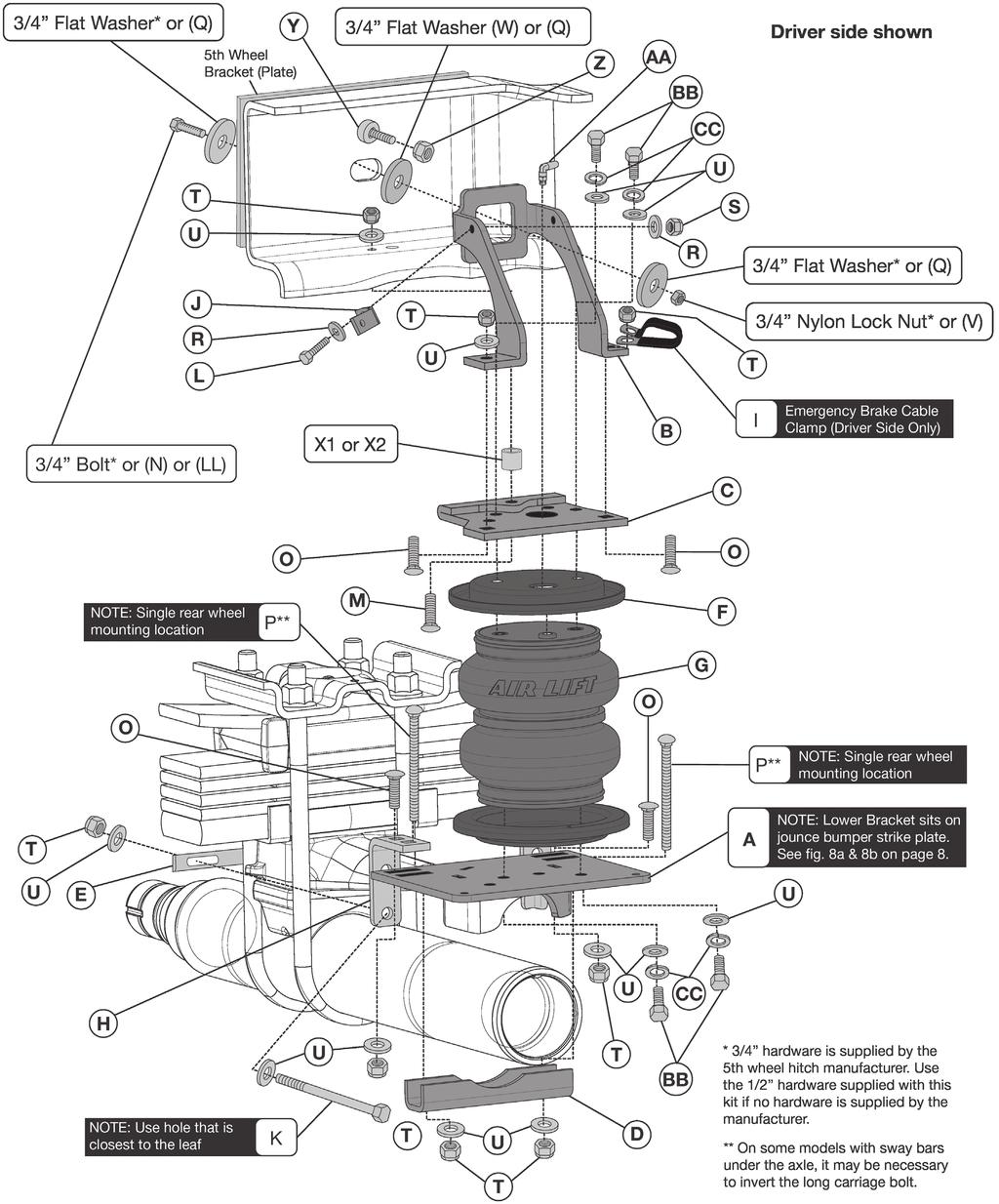
4 Installation Diagram fig. 1 2 MN-776
5 Hardware and Tools Lists HARDWARE LIST Item Part # Description... Qty A Lower Bracket...2 B Upper Brace...2 C Upper Bracket...2 D Axle Clamp Bar...2 E Spring Clamp Bar...2 F Roll Plate...4 G Bellows...2 H Four Hole Locating Bracket...4 I Emergency Brake Cable Clamp...1 J L Bracket...1 K /8-16 x 5.5 Hex Head Cap Screw...4 L /4-20 x 1 Hex Head Cap Screw...1 M /8-16 x 2.5 Carriage Bolt...2 N /2-13 x 3 Hex Head Cap Screw...2 O /8-16 x 1.25 Carriage Bolt...8 P /8-16 x 10 Carriage Bolt...4 Q /2 Thick Flat Washer...6 R Flat Washer # S /4-20 Nylon Lock Nut...1 T /8-16 Nylon Lock Nut...18 Item Part # Description... Qty U /8 Flat Washer...33 V /2-13 Nylon Lock Nut...2 W /4 Flat Washer...2 X Spacer...2 X Spacer...2 Y /16 Spacer...1 Z M Nylon Lock Nut...1 AA Swivel Elbow Fitting...2 BB /8-24 x 7/8 Hex Head Cap Screw..8 CC /8 Lock Washer...8 DD* Zip Ties...6 EE /16 Lock Washer...2 FF Valve Caps...2 GG /16 Hex Nut...4 HH Rubber Washer...2 II Flat Washer...2 JJ Air Line Assembly...1 KK* Heat Shield Kit...1 LL /2-13 x 2 Hex Head Cap Screw...2 *Not shown TOOLS LIST Description...Qty 7/16 and 9/16 Open-end or box wrenches...2 Crescent wrench...1 Ratchet with 3/8, 9/16, & 1/2 deep well sockets...1 5/16 drill bits (very sharp)...1 DIR grinder...1 Hacksaw...1 Heavy duty drill...1 Torque wrench...1 Standard, metric and SAE sockets and wrenches...1 Hose cutter, razor blade, or sharp knife...1 Hoist or floor jacks...1 Safety stands...1 Safety glasses...1 Air compressor or compressed air source...1 Spray bottle with dish soap/water solution...1 STOP! Missing or damaged parts? Call Air Lift customer service at (800) for a replacement part. MN-776 3
6 Introduction The purpose of this publication is to assist with the installation, maintenance and troubleshooting of the air spring kit. utilizes sturdy, reinforced, commercial grade single or double, depending on the kit, convolute bellows. The bellows are manufactured like a tire with layers of rubber and cords that control growth. kits are recommended for most 3/4- and 1-ton pickups and SUVs with leaf springs and provide up to 5,000 pounds of load leveling support with air adjustability from PSI. It is important to read and understand the entire installation guide before beginning installation or performing any maintenance, service or repair. The information here includes a hardware list, tool list, step-by-step installation information, maintenance guidelines and operating tips. Air Lift Company reserves the right to make changes and improvements to its products and publications at any time. For the latest version of this manual, contact Air Lift Company at (800) or visit airliftcompany.com. IMPORTANT SAFETY NOTICE The installation of this kit does not alter the gross vehicle weight rating (GVWR) or payload of the vehicle. Check your vehicle s owner s manual and do not exceed the maximum load listed for your vehicle. Gross vehicle weight rating: The maximum allowable weight of the fully loaded vehicle (including passengers and cargo). This number along with other weight limits, as well as tire, rim size and inflation pressure data is shown on the vehicle s Safety Compliance Certification Label. Payload: The combined, maximum allowable weight of cargo and passengers that the truck is designed to carry. Payload is GVWR minus the base curb weight. NOTATION EXPLANATION Hazard notations appear in various locations in this publication. Information which is highlighted by one of these notations must be observed to help minimize risk of personal injury or possible improper installation which may render the vehicle unsafe. Notes are used to help emphasize areas of procedural importance and provide helpful suggestions. The following definitions explain the use of these notations as they appear throughout this guide. DANGER WARNING CAUTION INDICATES IMMEDIATE HAZARDS WHICH WILL RESULT IN SEVERE PERSONAL INJURY OR DEATH. INDICATES HAZARDS OR UNSAFE PRACTICES WHICH COULD RESULT IN SEVERE PERSONAL INJURY OR DEATH. INDICATES HAZARDS OR UNSAFE PRACTICES WHICH COULD RESULT IN DAMAGE TO THE MACHINE OR MINOR PERSONAL INJURY. Indicates a procedure, practice or hint which is important to highlight. 4 MN-776
7 Installing the System GETTING STARTED 1. Raise the vehicle and support the axle with jack stands, setting the jack stands as wide as possible on the axle (Fig. 2). fig Remove the jounce bumpers from under the frame, over the axle. 3. If necessary, disconnect the wiring harness from the driver side frame rail to gain clearance for the upper bracket. 4. For all dual rear wheel vehicles (DRW) it will be necessary to remove the sway bar strap and bolts holding the sway bar to the axle. Retain for later reinstallation. 5. If you have a fifth wheel hitch already installed, it will be necessary to remove the 3/4 hardware that bolts the side bracket to the outside of the frame above the axle (Fig. 1). Some hitch models have a spacer between the bracket and the frame rail. Be sure to reinstall the spacer when attaching the upper bracket. 6. In order to obtain clearance between the upper bracket and the emergency brake cable bolt, on the inside of the frame, it will be necessary to remove the bolt and reinsert through the emergency brake cable bracket, from the outside of the frame in. Install the 7/16 spacer (Y) on the bolt and cap with the new M nylon lock nut (Z) (Fig. 1). Tighten hardware securely. If your model truck has emission lines running along the inside of the frame rail (Fig. 3), it will be necessary to relocate those lines as follows. Follow the directions in the section, Attaching the Assemblies to the Frame for reattaching these lines. Carefully push the line holder out of the frame above the axle. Try to minimize damage because it will be reused later. It may also be helpful to remove any holders forward or rearward of the axle to aid in positioning the lines once the upper bracket has been installed (Fig. 3). Attach the L-bracket (J) to the back or front leg of the frame brace using the 1/4-20 x 1 hex head bolt (L), flat washers (R) and 1/4-20 nylon lock nut (S) supplied (Fig. 1). This L-bracket will eventually be used to attach the previously removed emissions line. Do not attach the line holder to it at this time. Emissions lines Line holder fig. 3 Electrical wiring loom MN-776 5

8 SIDE BRACE INSTALLATION fig Set the upper brace (B) into the driver and passenger side frame (Fig. 4). If you have no fifth wheel hitch or a hitch that does not have a plate running alongside the full length of the frame (these will have an L bracket forward and behind the axle leaving the middle frame open) use the 1/2-13 x 2 hex cap screw (LL) with a flat washer (Q) through the slot in the side of the frame, then through another flat washer (Q) and finally through the upper brace. Cap with a flat washer (Q) and a 1/2-13 nylon lock nut (V) (Fig. 4). Leave loose at this time. OR If you have an aftermarket fifth wheel hitch that has a bracket (plate) running along side of the frame and it used this slot to secure the bracket to the frame with existing hardware, install the existing hardware previously removed in the getting started section from the fifth wheel installation for securing the brace (Fig. 4). Make sure to install the large 3/4 flat washer (W) between the brace and frame (Figs. 1 & 4). Do not tighten at this time. OR If you have an aftermarket fifth wheel hitch that has a bracket (plate) running along side of the frame and it does not have any attaching hardware on the side where the slot in the frame is, it will be necessary to drill a 1/2 hole through the plate using the slot in the frame as a template. It may be necessary to mark and remove the bracket (plate) from the side of the frame in order to drill the hole correctly. Re-attach once the hole is drilled. Insert a 1/2-13 x 3 hex head cap screw (N) with a 1/2 thick flat washer (Q) through the fifth wheel plate previously drilled, the frame, then through another 1/2 thick flat washer (Q) and finally the upper frame brace. Cap with a 1/2 thick flat washer (Q) and a 1/2-13 nylon lock nut (V) (Fig. 4). Leave loose at this time. BELLOWS AND BRACKET ASSEMBLY 1. Set a roll plate (F) over the top and bottom of the bellows (G) (Fig. 1). The radiused (rounded) edge of the roll plate (F) will be towards the bellows so that the bellows is seated inside both roll plates. 6 MN-776
9 2. Install the swivel elbow fitting (AA) into the top of the bellows finger tight. Tighten the swivel fitting one and a half turns. 3. The lower bracket (A) has two sets of bellows mounting holes. Using the corresponding holes in the lower bracket designated (fig. 5), attach the bellows to the brackets using the 3/8 flat washers (U), lock washers (CC), and 3/8-24 x 7/8 hex head cap screws (BB). Tighten both mounting screws securely. The fitting on top of the bellows points inward (Fig. 7). Outside (wheel) Left (driver) side holes (A) Lower bracket Right (passenger) side holes 4. Insert two 3/8-16 x 1.25 carriage bolts (O) up through the bottom of the upper brackets (Fig. 6), through the two square holes that are on the corresponding side. Also, insert one 3/8-16 x 2.5 carriage bolt (M) through the remaining hole. The head of this carriage bolt will be hidden once mounted to the bellows. 5. Set the driver side (left) upper bracket onto the driver side bellows assembly previously assembled, using the holes in the upper bracket designated (Fig. 6), and attach to the bellows with two 3/8 flat washers (U), lock washers (CC), and 3/8-24 x 7/8 hex head cap screws (BB). Tighten both mounting screws securely. 6. Repeat the above process for the opposite side assembly (Fig. 7). 7. Depending on the model of the truck, there are two spacer (X1 or X2) lengths that are supplied to properly fit between the frame jounce bumper bracket and frame. Use the spacer that can be inserted where the stock jounce bumper was removed, which when butted against the frame, will be flush (or close to) the bottom of the jounce bumper bracket that is riveted to the frame. The upper bracket, when in position, should rest on the spacer and the stock jounce bumper bracket. fig. 5 fig. 6 (C) Upper bracket (X1 or X2) (T), (CC), (BB) (M) Passenger Side (G) Bellows (A) Lower bracket (C) Upper bracket Driver Side (O) fig. 7 Left (Driver Side shown) MN-776 7
 assembly onto the jounce bumper strike plate (Figs. 8a & 8b). Raise the axle just enough to insert the 3/8-16 x 2.")
10 ATTACHING THE ASSEMBLIES TO THE FRAME 1. If not done so yet, drop the axle or raise the frame up to make room for the assemblies to be put into position. 2. Set the left (driver side) assembly onto the jounce bumper strike plate (Figs. 8a & 8b). Raise the axle just enough to insert the 3/8-16 x 2.5 long carriage bolt (M) (that is installed in the upper bracket) through the existing jounce bumper hole in the bottom of the frame. At the same time, line up the upper brace previously installed onto the remaining two 3/8-16 x 1.25 carriage bolts (O) in the upper bracket. Do this just enough for the carriage bolt to hold the assembly into position on the jounce bumper strike plate (Figs. 1 & 8b). : Driver side shown (A) Lower bracket Jounce bumper strike plate (located above axle) fig. 8a fig. 8b CAUTION 3. Set the right (passenger side) assembly into position on the axle the same way the left side was positioned (Fig. 1). 4. Raise the axle or lower the frame down so that the round spacer (X1 or X2) on the upper bracket inserts into the stock jounce bumper bracket hole (on both sides). 5. Install the 3/8 flat washer (U) and a 3/8-16 nylon lock nut (T) on the 3/8-16 x 2.5 carriage bolt (M) that went through the existing jounce bumper hole and tighten securely on both sides (Fig. 1). BE SURE NOT TO PINCH THE PREVIOUSLY MOVED WIRING OR LINES INSIDE THE LEFT FRAME RAIL. 6. Install the emergency brake cable clamp (I) over the emergency brake cable and attach to the forward brace/upper bracket bolt (O) (Fig. 1). Cap with a 3/8 nylon lock nut (T). Both sides: Cap the remaining brace/upper bracket carriage bolts (O) with a 3/8 flat washer (U) and 3/8-16 nylon lock nut (T) and tighten all hardware securely. 7. With the spacers (X1 or X2) on the upper brackets tight in the frame and the braces tight to the upper bracket, tighten the 1/2 or 3/4 hardware previously installed, that hold the braces to the frame. Tighten both sides securely. 8. If so equipped with the emissions line previously loosened from the frame, insert the line holder post into the L-bracket (J) attached to the back or front leg of the upper left brace (B) (Fig. 9). It may be necessary to move the line holder post forward or back on the lines to line up correctly with the L-bracket hole. Reattach any line holders removed forward or behind the axle, if possible, that were removed to aid in positioning the upper bracket. Emissions line holder (stock) Option: (J) L-bracket fig. 9 (J) L-bracket 8 MN-776
11 CAUTION LOWER BRACKET ATTACHMENT ATTACHING THE LOWER BRACKET WILL DEPEND ON THE MODEL TRUCK YOU HAVE. SEE FIGURES 10 AND 11 TO DETERMINE WHICH HOLES TO USE FOR INSERTING THE CARRIAGE BOLTS. : Single rear wheel mounting location shown. P** G O O P** : Single rear wheel mounting location shown. T A : Lower Bracket sits on jounce bumper strike plate. See fig. 8a & 8b on page 8. U E U H U T U CC BB fig. 10 : Use hole that is closest to the leaf spring! K T U T D ** On some models with sway bars under the axle, it may be necessary to invert the long carriage bolt. 1. Insert a 3/8-16 x 5.5 hex head bolt (K) and 3/8 flat washer (U) into one of the two bottom holes of the locating bracket (H) (Fig. 11). Use the hole that is closest to the leaf spring. 2a. If you are installing this kit on a single rear wheel (SRW) vehicle, use position 2 to insert the long 3/8-16 x 10 carriage bolt (P) through the top of the locating bracket and lower bracket (Fig. 11). 2b. If you are installing this kit on a dual rear wheel (DRW) vehicle, use position 1 to insert the long 3/8-16 x 10 carriage bolt (P) through the top of the locating bracket and lower bracket (Fig. 11). 3. Attach the locating bracket (H) to the lower bracket with a 3/8-16 x 1.25 carriage bolt (O), 3/8 flat washer (U) and 3/8-16 nylon lock nut (T) using the remaining slot in the top of the locating bracket. Leave loose at this time. 4. Push the front and back locating brackets against the stock u-bolts and tighten the short carriage bolts at this time. 5. Using the 3/8-16 x 5.5 hex head bolts (K) and 3/8 flat washers (U) previously installed on the locating brackets, insert them into the spring clamp bar (E) on the opposite side of the leaf spring assembly (Fig. 11). Cap with 3/8 flat washers (U) and 3/8-16 nylon lock nuts (T). Leave loose at this time. Position 1 Position 1 Position 2 Position 2 (A) Lower bracket (H) Locating bracket fig. 11 MN-776 9
12 6. Set the axle clamp bar (D) onto the long 3/8-16 x 10 carriage bolts (Q) (Fig. 1) and cap with 3/8 flat washers (U) and 3/8-16 nylon lock nuts (T). If you have a sway bar under the axle and the 3/8-16 x 10 long carriage bolt (P) interferes, invert the carriage bolt. 7. Carefully draw the side hardware and axle hardware evenly. Torque the spring clamp bar bolts to 10 lb.-ft. (14Nm) and the axle clamp bar bolts to 16 lb.-ft. (22Nm) Repeat for opposite side. Trim carriage bolts below nylon lock nuts if necessary. For 2WD and 4WD DRW vehicles, in order to install the sway bar and sway bar retaining straps back onto the axle, it will be necessary to slot the retaining straps (Fig. 12). Reattach the sway bar once this is done. Grind slot larger Grind slot larger fig MN-776
13 Installing the Air Lines This section explains how to set up the air spring kit to be controlled with Schrader valves and a separate compressed air source. An on-board air compressor system allows for hassle-free control of the air springs. Learn more about Air Lift control systems at 1. Choose a convenient location for mounting the inflation valves (Fig. 13). Popular locations for the inflation valve are: a. The wheel well flanges b. The license plate recess in bumper c. Under the gas cap access door d. Through the license plate Option 1: Option 2: fig. 13 TECH TIP Whatever the chosen location, make sure there is enough clearance around the inflation valves for an air chuck. 2. Drill 5/16 holes to install the inflation valves. 3. Cut the air line assembly in two equal lengths. 4. Place a 5/16 nut Air line to and star washer on Vehicle body air spring the air valve. Leave or bumper enough of the inflation Schrader valve in front of the valve Flat washer nut to extend through Hex nut Valve the hole and have Cap Star room for the rubber washer washer, flat washer, Rubber washer and 5/16 nut and cap. There should be Hex nut enough valve exposed fig. 14 after installation approximately 1/2 to easily apply a pressure gauge or an air chuck (Fig. 14). 5. Push the inflation valve through the hole and use the rubber washer, flat washer, and another 5/16 nut to secure it in place. Tighten the nuts to secure the assembly. 6. Route the air line along the frame to the fitting on the air spring. Keep AT LEAST 6 of clearance between the air line and the exhaust system. Avoid sharp bends and edges. Use zip ties to secure the air line to fixed points along the chassis. Be sure that the tie straps are tight, but do not pinch the air line. Leave at least 2 of slack to allow for any movement that might pull on the air line. 7. Cut off the air line, leaving approximately 12 of extra air line. A clean square cut will prevent leaks. Insert the air line into the air fitting. This is a push-to-connect fitting. Wiggle the hose back and forth while inserting to make sure the hose bottoms out in the fitting to obtain a good seal. MN

14 TIPS FOR INSTALLING AIR LINES When cutting air lines, use a sharp knife or a hose cutter and make clean, square cuts (Fig. 15). Do not use scissors or wire cutters because these tools may deform the air line, causing it to leak around fittings. Do not cut the lines at an angle. Do not bend the 1/4 hose at a radius of less than 1 or bend the 3/8 hose at a radius of less than 1 1/2. Do not put side load pressure on fitting. The hose should be straight beyond the fitting for 1 before bending. Inspect hose for scratches that run lengthwise on hose prior to installation. Contact Air Lift customer service at (800) if the air line is damaged. fig. 15 Go to air-lift.co/cuttingairline to watch a video demonstrating proper air line cutting. INSTALLING THE HEAT SHIELD 1. Bend tabs to provide a dead air space between exhaust pipe and heat shield. (Fig. 16) Attach the heat shield to the exhaust pipe using the clamps. Bend the heat shield for maximum clearance to the air spring. Some vehicles have large resonators in this area; it will be necessary to double up on the clamps to fit these models (Fig. 16). Exhaust resonator Bend tabs 1/2 dead air space Double up supplied hose clamps provided fig MN-776
15 Before Operating CHECKING FOR LEAKS CAUTION 1. Inflate the air spring to 30 PSI. 2. Spray all connections and the inflation valves with a solution of 1/5 liquid dish soap and 4/5 water. Spot leaks easily by looking for bubbles in the soapy water. 3. After the test, deflate the springs to the minimum pressure required to restore the system to normal ride height. Do not deflate to lower than 5 PSI. 4. Check the air pressure again after 24 hours. A 2-4 PSI loss after initial installation is normal. Retest for leaks if the loss is more than 5 PSI. FIXING LEAKS 1. If there is a problem with the swivel fitting: a. Check the air line connection by deflating the spring and removing the line by pulling the collar against the fitting and pulling firmly on the air line. Trim 1 off the end of the air line. Be sure the cut is clean and square (see Fig. 15). Reinsert the air line into the push-to-connect fitting. b. Check the threaded connection by tightening the swivel fitting another half turn. If it still leaks, deflate the air spring, remove the fitting, and re-coat the threads with thread sealant. Reinstall by hand tightening as much as possible and then use a wrench for an additional two turns. 2. If there is a problem with the inflation valve: a. Check the valve core by tightening it with a valve core tool. b. Check the air line by removing the air line from the barbed type fitting. Cut the air line off a few inches in front of the fitting and use a pair of pliers or vice grips to pull/twist the air line off of the fitting. DO NOT CUT OFF THE AIR LINE COMPLETELY AS THIS WILL USUALLY NICK THE BARB AND RENDER THE FITTING USELESS. 3. If the preceding steps have not resolved the problem, call Air Lift customer service at (800) MN
16 INSTALLATION CHECKLIST Clearance test Inflate the air springs to PSI and make sure there is at least 1/2 clearance from anything that might rub against each sleeve. Be sure to check the tire, brakes, frame, shock absorbers and brake cables. Leak test before road test Inflate the air springs to PSI and check all connections for leaks. All leaks must be eliminated before the vehicle is road tested. Heat test Be sure there is sufficient clearance from heat sources, at least 6 for air springs and air lines. If a heat shield was included in the kit, install it. If there is no heat shield, but one is required, call Air Lift customer service at (800) Fastener test Recheck all bolts for proper torque. Road test The vehicle should be road tested after the preceding tests. Inflate the springs to recommended driving pressures. Drive the vehicle 10 miles and recheck for clearance, loose fasteners and air leaks. Operating instructions If professionally installed, the installer should review the operating instructions with the owner. Be sure to provide the owner with all of the paperwork that came with the kit. POST-INSTALLATION CHECKLIST Overnight leak down test Recheck air pressure after the vehicle has been used for 24 hours. If the pressure has dropped more than 5 PSI, then there is a leak that must be fixed. Either fix the leak yourself or return to the installer for service. Air pressure requirements It is important to understand the air pressure requirements of the air spring system. Regardless of load, the air pressure should always be adjusted to maintain adequate ride height at all times while driving. Thirty-day or 500-mile test Recheck the air spring system after 30 days or 500 miles, whichever comes first. If any part shows signs of rubbing or abrasion, the source should be identified and moved, if possible. If it is not possible to relocate the cause of the abrasion, the air spring may need to be remounted. If professionally installed, the installer should be consulted. Check all fasteners for tightness. 14 MN-776
17 Product Use, Maintenance and Servicing Minimum Recommended Pressure Maximum Air Pressure 5 PSI 100 PSI CAUTION MAINTENANCE GUIDELINES By following the steps below, vehicle owners will obtain the longest life and best results from their air springs. 1. Check air pressure weekly. 2. Always maintain normal ride height. Never inflate beyond 100 PSI. 3. If the system develops an air leak, use a soapy water solution (1/5 liquid dish soap and 4/5 water) to check all air line connections and the inflation valve core before deflating and removing the air spring. FOR SAFETY AND TO PREVENT POSSIBLE DAMAGE TO THE VE- HICLE, DO NOT EXCEED MAXIMUM GROSS VEHICLE WEIGHT RAT- ING (GVWR), AS INDICATED BY THE VEHICLE MANUFACTURER. AL- THOUGH THE AIR SPRINGS ARE RATED AT A MAXIMUM INFLATION PRESSURE OF 100 PSI, THE AIR PRESSURE ACTUALLY NEEDED IS DEPENDENT ON LOAD AND GVWR. 4. Loaded vehicles require at least 25 PSI. A loaded vehicle refers to a vehicle with a heavy bed load, a trailer or both. Never exceed GVWR, regardless of air spring, air pressure or other load assist. The springs in this kit will support approximately 40 pounds of load (combined on both springs) for each 1 PSI of pressure. The required air pressure will vary depending on the state of the original suspension. Operating the vehicle below the minimum air spring pressure will void the Air Lift warranty. 5. When increasing load, always adjust air pressure to maintain normal ride height. Increase or decrease pressure from the system as necessary to attain normal ride height for optimal ride and handling. Remember that loads carried behind the axle (including tongue loads) require more leveling force (pressure) than those carried directly over the axle. 6. Always add air to springs in small quantities, checking the pressure frequently. 7. Should it become necessary to raise the vehicle by the frame, make sure the system is at minimum pressure (5 PSI) to reduce the tension on the suspension/ brake components. Use of on-board leveling systems do not require deflation or disconnection. 8. Periodically check the air spring system fasteners for tightness. Also, check the air springs for any signs of rubbing. Realign if necessary. 9. On occasion, give the air springs a hard spray with a garden hose to remove mud, sand, gravel or other debris. MN
18 TUNING THE AIR PRESSURE Pressure determination comes down to three things level vehicle, ride comfort and stability. 1. Level vehicle If the vehicle s headlights are shining into the trees or the vehicle is leaning to one side, then it is not level (Fig. 17). Raise the air pressure to correct either of these problems and level the vehicle. 2. Ride comfort If the vehicle has a rough or harsh ride it may be due to either too much pressure or not enough (Fig. 18). Try different pressures to determine the best ride comfort. 3. Stability Stability translates into safety and should be the priority, meaning the driver may need to sacrifice a perfectly level and comfortable ride. Stability issues include roll control, bounce, dive during braking and sponginess (Fig. 19). Tuning out these problems usually requires an increase in pressure. Bad headlight aim fig. 17 Rough ride fig. 18 Sway and body roll fig. 19 GUIDELINES FOR ADDING AIR 1. Start with the vehicle level or slightly above. 2. When in doubt, always add air. 3. If the front of the vehicle dives while braking, increase the pressure in the front air bags, if equipped. 4. If it is ever suspected that the air bags have bottomed out, increase the pressure (Fig. 20). 5. Adjust the pressure up and down to find the best ride. 6. If the vehicle rocks and rolls, adjust the air pressure to reduce movement. 7. It may be necessary to maintain different pressures on each side of the vehicle. Loads such as water, fuel, and appliances will cause the vehicle to be heavier on one side (Fig. 21). As much as a 50 PSI difference is not uncommon. Bottoming out Unlevel fig Level fig. 21 MN-776
19 Troubleshooting Guide PROBLEM CAUSE SOLUTION System won t maintain pressure overnight. Improperly installed air line, air line has holes or cracks. Leak test the air line connections, the threaded connection into the air spring, and all fittings in the control system. Air spring or air line leak. Fitting seal or air line is compromised. Check to make sure air lines are seated in connectors. Inspect fittings with soapy water. Trim hose or re-seal fitting. Ensure lines are cut straight. Corner won't raise or air leak develops. Look for a kink or fold in the air line. Replace any air line that has been kinked. FREQUENTLY ASKED QUESTIONS Q. Will installing air springs increase the weight ratings of a vehicle? No. Adding air springs will not change the weight ratings (GAWR, GCWR and/ or GVWR) of a vehicle. Exceeding the GVWR is dangerous and voids the Air Lift warranty. Q. Is it necessary to keep air in the air springs at all times and how much pressure will they need? For, the recommended minimum air pressure is 5 PSI, but it can safely be run at zero air pressure unladen (no load). Q. Is it necessary to add a compressor system to the air springs? No. Air pressure can be adjusted with any type of compressor as long as it can produce sufficient pressure to service the springs. Even a bicycle tire pump can be used, but it s a lot of work. Q. How long should air springs last? If the air springs are properly installed and maintained they can last indefinitely. Q. Will raising the vehicle on a hoist for service work damage the air springs? No. The vehicle can be lifted on a hoist for short-term service work such as tire rotation or oil changes. However, if the vehicle will be on the hoist for a prolonged period of time, support the axle with jack stands in order to take the tension off of the air springs. MN
20 Notes 18 MN-776
21 Notes MN
22 20 MN-776
23 Limited Warranty and Return Policy Replacement Part Information Contact Information Air Lift Company provides a limited lifetime warranty to the original purchaser of its Load Support products, that the products will be free from defects in workmanship and materials when used on cars and trucks as specified by Air Lift Company and under normal operating conditions, subject to the requirements and exclusions set forth in the full Limited Warranty and Return Policy that is available online at For additional warranty information contact Air Lift Company customer service. If replacement parts are needed, contact the local dealer or call Air Lift customer service at (800) Most parts are immediately available and can be shipped the same day. Contact Air Lift Company customer service at (800) first if: Parts are missing from the kit. Need technical assistance on installation or operation. Broken or defective parts in the kit. Wrong parts in the kit. Have a warranty claim or question. Contact the retailer where the kit was purchased: If it is necessary to return or exchange the kit for any reason. If there is a problem with shipping if shipped from the retailer. If there is a problem with the price. Mailing address P.O. Box Lansing, MI Shipping address 2727 Snow Road for returns Lansing, MI Phone Toll free: (800) International: (517) Web address service@airliftcompany.com MN
24 Need Help? Contact Air Lift Company customer service department by calling (800) For department calls from outside by the calling USA or (800) Canada, dial (517) Contact Air Lift Company customer service For calls from outside the USA or Canada, dial (517) Thank you for purchasing Air Lift products the professional installer s choice! Air Lift Company 2727 Snow Road Lansing, MI or P.O. Box Lansing, MI Toll Free (800) Local (517) Fax (517) Printed in the USA JJC-0117
Kit Number INSTALLATION GUIDE ADJUSTABLE AIR HELPER SPRINGS TOW AND HAUL WITH SAFETY AND COMFORT TM
 ADJUSTABLE AIR HELPER SPRINGS TOW AND HAUL WITH SAFETY AND COMFORT TM Kit Number 88344 INSTALLATION GUIDE For maximum effectiveness and safety, please read these instructions completely before proceeding
LoadLIFTER. Kit Chevrolet Silverado/ GMC Sierra 3500 Commercial Cab and Chassis INSTALLATION GUIDE
 LoadLIFTER 5000 Kit 57286 2001- Chevrolet Silverado/ GMC Sierra 3500 Commercial Cab and Chassis MN-721 (011006) ERN 6638 INSTALLATION GUIDE For maximum effectiveness and safety, please read these instructions
Kit Number INSTALLATION GUIDE ADJUSTABLE AIR HELPER SPRINGS TOW AND HAUL WITH SAFETY AND COMFORT TM
 ADJUSTABLE AIR HELPER SPRINGS TOW AND HAUL WITH SAFETY AND COMFORT TM Kit Number 88299 INSTALLATION GUIDE For maximum effectiveness and safety, please read these instructions completely before proceeding
Kit Ford Excursion, F-250/F-350 Super Duty, F-450/F-550 Commercial
 Kit 57154 Ford Excursion, F-250/F-350 Super Duty, F-450/F-550 Commercial MN-505 (041703) ECR 8760 Watch the video Info on next page INSTALLATION GUIDE For maximum effectiveness and safety, please read
LoadLIFTER. Kit Chevrolet/GMC 2500/3500HD Pickups 2WD & 4WD INSTALLATION GUIDE. Watch the video Info on next page
 LoadLIFTER 5000 Kit 57338 2011- Chevrolet/GMC 2500/3500HD Pickups 2WD & 4WD MN-731 (051603) ECR 8467 Watch the video Info on next page INSTALLATION GUIDE For maximum effectiveness and safety, please read
Kit & INSTALLATION GUIDE. Watch the video Info on next page
 Kit 57275 & 57285 (101704) ECR 8760 Watch the video Info on next page INSTALLATION GUIDE For maximum effectiveness and safety, please read these instructions completely before proceeding with installation.
Kit Dodge Ram 2500HD
 Kit 57289 Dodge Ram 2500HD MN-930 (021407) ECR 8041 INSTALLATION GUIDE For maximum effectiveness and safety, please read these instructions completely before proceeding with installation. Failure to read
Kit Number INSTALLATION GUIDE ADJUSTABLE AIR HELPER SPRINGS TOW AND HAUL WITH SAFETY AND COMFORT TM
 ADJUSTABLE AIR HELPER SPRINGS TOW AND HAUL WITH SAFETY AND COMFORT TM Kit Number 88203 INSTALLATION GUIDE For maximum effectiveness and safety, please read these instructions completely before proceeding
RideCONTROL. Kit Toyota Tundra 2WD & 4WD INSTALLATION GUIDE
 RideCONTROL Kit 59530 Toyota Tundra 2WD & 4WD IMPORTANT: This kit does not fit 2000-06 Toyota Tundra 2WD & 4WD pickups equipped with the TRD Package with 275/65-18 wheels and tires. MN-420 (071512) ECR
I. Assembling the Air Spring
 B F H G D FRONT I Assembling the Air Spring 1 Install 90 degree air swivel fitting (D) to the top of the bellow This fitting is precoated with sealant Using an open-end wrench, tighten 1 and 1 /2 turns
Kits and INSTALLATION GUIDE. Ford F & 4 Wheel Drive
 Kits 57268 and 57284 Ford F-150 2 & 4 Wheel Drive MN-957 (011502) ERN 8111/8112 INSTALLATION GUIDE For maximum effectiveness and safety, please read these instructions completely before proceeding with
Tools Needed. I. Getting Started
 5 /16 ", 7 /16 ", 9 /16 " and 19mm open-end or box wrenches Crescent Wrench Ratchet with 9 /16 " and 1 /2 " deep well sockets 3 /8 " and 5 /16 " drill bits (very sharp) Heavy Duty Drill Torque Wrench Tools
Kit INSTALLATION GUIDE. Ford F-150
 Kit 59570 Ford F-150 TM MN-962 (011503) ERN 8162 INSTALLATION GUIDE For maximum effectiveness and safety, please read these instructions completely before proceeding with installation. Failure to read
Kit Number INSTALLATION GUIDE ADJUSTABLE AIR HELPER SPRINGS TOW AND HAUL WITH SAFETY AND COMFORT TM
 ADJUSTABLE AIR HELPER SPRINGS TOW AND HAUL WITH SAFETY AND COMFORT TM Kit Number 88212 INSTALLATION GUIDE For maximum effectiveness and safety, please read these instructions completely before proceeding
Kit Ford Super Duty F-250/F-350, SRW & DRW
 Kit 57399 Ford Super Duty F-250/F-350, SRW & DRW MN-1026 (021611) ECR 8695 Watch the video Info on next page INSTALLATION GUIDE For maximum effectiveness and safety, please read these instructions completely
Kit Chevrolet/GMC Heavy Duty. Installation Guide
 Installation Guide Kit 57538 Chevrolet/GMC Heavy Duty Representative vehicle image MN-1034 (011612) ERN 8635 For maximum effectiveness and safety, please read these instructions completely before proceeding
Kit 59565, Chevrolet Silverado 1500 and GMC Sierra 1500
 Kit 59565, 59567 Chevrolet Silverado 1500 and GMC Sierra 1500 MN-670 (061706) ECR 8870 INSTALLATION GUIDE For maximum effectiveness and safety, please read these instructions completely before proceeding
Kit Chevrolet/GMC Heavy Duty. Installation Guide
 Installation Guide Kit 57538 Chevrolet/GMC Heavy Duty Representative vehicle image MN-1034 (021810) ECR 9155 For maximum effectiveness and safety, please read these instructions completely before proceeding
Kit Number INSTALLATION GUIDE ADJUSTABLE AIR HELPER SPRINGS TOW AND HAUL WITH SAFETY AND COMFORT TM
 ADJUSTABLE AIR HELPER SPRINGS TOW AND HAUL WITH SAFETY AND COMFORT TM Kit Number 88208 INSTALLATION GUIDE For maximum effectiveness and safety, please read these instructions completely before proceeding
Kit INSTALLATION GUIDE. For maximum effectiveness and safety, please read these instructions completely before proceeding with installation.
 Kit 60809 MN-639 (021707) ECR 8866 INSTALLATION GUIDE For maximum effectiveness and safety, please read these instructions completely before proceeding with installation. Failure to read these instructions
Kit No Please read these instructions completely before proceeding with installation. Air Spring Kit Parts List. Attaching Hardware
 Kit No. 57340 MN-431 (02409) NPR 4796 Please read these instructions completely before proceeding with installation by www.airliftcompany.com Air Spring Kit Parts List A B1 B2 Item Description Quantity
No & INSTALLATION GUIDE
 No. 57215 & 57207 MN-387 (31210) ECR 7433 INSTALLATION GUIDE For maximum effectiveness and safety, please read these instructions completely before proceeding with installation. Failure to read these instructions
Kit Number INSTALLATION GUIDE ADJUSTABLE AIR HELPER SPRINGS TOW AND HAUL WITH SAFETY AND COMFORT TM
 ADJUSTABLE AIR HELPER SPRINGS TOW AND HAUL WITH SAFETY AND COMFORT TM Kit Number 88138 INSTALLATION GUIDE For maximum effectiveness and safety, please read these instructions completely before proceeding
Kit Honda Odyssey, Honda Pilot, & Acura MDX
 TM Kit 60815 Honda Odyssey, Honda Pilot, & Acura MDX Cover illustration may not depict actual kit. MN-692 (041801) ECR 8900 INSTALLATION GUIDE For maximum effectiveness and safety, please read these instructions
Kit Number INSTALLATION GUIDE ADJUSTABLE AIR HELPER SPRINGS TOW AND HAUL WITH SAFETY AND COMFORT TM
 ADJUSTABLE AIR HELPER SPRINGS TOW AND HAUL WITH SAFETY AND COMFORT TM Kit Number 88205 INSTALLATION GUIDE For maximum effectiveness and safety, please read these instructions completely before proceeding
Representative vehicle image
 Installation Guide Kit 57589 Dodge/RAM Heavy Duty Representative vehicle image For maximum effectiveness and safety, please read these instructions completely before proceeding with installation. Failure
Kit Number INSTALLATION GUIDE ADJUSTABLE AIR HELPER SPRINGS
 ADJUSTABLE AIR HELPER SPRINGS Kit Number 88215 INSTALLATION GUIDE For maximum effectiveness and safety, please read these instructions completely before proceeding with installation. Failure to read these
Kits Installation Guide. Dodge/RAM WD and 4WD
 S E R I E S TM Installation Guide Dodge/RAM 1500 2WD and 4WD Kits 57370 88370 89370 For maximum effectiveness and safety, please read these instructions completely before proceeding with installation.
Kit No Please read these instructions completely before proceeding with installation. Parts List G J I K L H CC FF DD MN-505 (01201) NPR 3733
 NPR 3733") Kit No. 57154 MN-505 (01201) NPR 3733 Please read these instructions completely before proceeding with installation Parts List by www.airliftcompany.com Item P/N Description Quantity A 58407 Air Spring
Kit No. 57154 MN-505 (01201) NPR 3733 Please read these instructions completely before proceeding with installation Parts List by www.airliftcompany.com Item P/N Description Quantity A 58407 Air Spring
Kit Number INSTALLATION GUIDE ADJUSTABLE AIR HELPER SPRINGS TOW AND HAUL WITH SAFETY AND COMFORT TM
 ADJUSTABLE AIR HELPER SPRINGS TOW AND HAUL WITH SAFETY AND COMFORT TM Kit Number 88105 INSTALLATION GUIDE For maximum effectiveness and safety, please read these instructions completely before proceeding
Kit INSTALLATION GUIDE. For maximum effectiveness and safety, please read these instructions completely before proceeding with installation.
 Kit 80537 MN-613 (031707) ECR 8866 INSTALLATION GUIDE For maximum effectiveness and safety, please read these instructions completely before proceeding with installation. Failure to read these instructions
Kit Number INSTALLATION GUIDE ADJUSTABLE AIR HELPER SPRINGS TOW AND HAUL WITH SAFETY AND COMFORT TM
 ADJUSTABLE AIR HELPER SPRINGS TOW AND HAUL WITH SAFETY AND COMFORT TM Kit Number 88200 INSTALLATION GUIDE For maximum effectiveness and safety, please read these instructions completely before proceeding
Kits Installation Guide Chevrolet/GMC 2500/3500. Watch the video Info on next page
 S E R I E S TM Installation Guide 2001-10 Chevrolet/GMC 2500/3500 Kits 57275 88275 89275 Watch the video Info on next page For maximum effectiveness and safety, please read these instructions completely
Kits Installation Guide current Chevrolet Silverado HD and GMC Sierra HD. Watch the video Info on next page
 S E R I E S TM Installation Guide 2011-current Chevrolet Silverado HD and GMC Sierra HD Kits 57338 88338 89338 Watch the video Info on next page For maximum effectiveness and safety, please read these
Kit No Please read these instructions completely before proceeding with installation. Figure 1. Forward. Passenger-Side View
 Kit No. 57345 90 Air Fitting (G) MN-520 (01206) NPR 3902 Please read these instructions completely before proceeding with installation by www.airliftcompany.com 7 16 "-14 Lock Nut (E) Air Line (AA) Upper
Kit No Please read these instructions completely before proceeding with installation. Air Spring Kit Parts List. Bracket Attaching Hardware
 Kit No. 59532 MN-572 (021108) ECR 7136 Please read these instructions completely before proceeding with installation Air Spring Kit Parts List A Item Description Quantity A Air Sleeves 2 B Upper Brackets
Kit INSTALLATION GUIDE. Honda Odyssey, Honda Pilot, & Acura MDX
 Kit 60815 Honda Odyssey, Honda Pilot, & Acura MDX Cover illustration may not depict actual kit. MN-692 (021202) ECR 7276 INSTALLATION GUIDE For maximum effectiveness and safety, please read these instructions
Kit Number INSTALLATION GUIDE ADJUSTABLE AIR HELPER SPRINGS TOW AND HAUL WITH SAFETY AND COMFORT TM
 ADJUSTABLE AIR HELPER SPRINGS TOW AND HAUL WITH SAFETY AND COMFORT TM Kit Number 88340 INSTALLATION GUIDE For maximum effectiveness and safety, please read these instructions completely before proceeding
Kits Installation Guide current Chevrolet Silverado HD and GMC Sierra HD. Watch the video Info on next page
 S E R I E S TM Installation Guide 2011-current Chevrolet Silverado HD and GMC Sierra HD Kits 57338 88338 89338 Watch the video Info on next page For maximum effectiveness and safety, please read these
Kits & INSTALLATION GUIDE Dodge Durango (AWD)* Jeep Grand Cherokee (2WD/4WD)**
* Jeep Grand Cherokee (2WD/4WD)**") Kits 60824 & 60825 2011- Dodge Durango (AWD)* 2011- Jeep Grand Cherokee (2WD/4WD)** MN-762 (021710) ECR 8919 * DOES NOT FIT DURANGO HEAT AND R/T APPLICATIONS ** DOES NOT FIT JEEP QUADRA-LIFT EQUIPPED AND
Kits 60824 & 60825 2011- Dodge Durango (AWD)* 2011- Jeep Grand Cherokee (2WD/4WD)** MN-762 (021710) ECR 8919 * DOES NOT FIT DURANGO HEAT AND R/T APPLICATIONS ** DOES NOT FIT JEEP QUADRA-LIFT EQUIPPED AND
Kit No Please read these instructions completely before proceeding with installation. Air Spring Kit Parts List. Bracket Attaching Hardware
 Kit No. 59537 MN-461 (021108) ECR 7136 Please read these instructions completely before proceeding with installation Air Spring Kit Parts List Item Description Quantity A Air Sleeves 2 B Upper Brackets
Kit INSTALLATION GUIDE. Front Application. Scion xa & xb
 Kit 75572 Scion xa & xb Front Application MN-610 (101710) ECR 8900 INSTALLATION GUIDE For maximum effectiveness and safety, please read these instructions completely before proceeding with installation.
Kits Installation Guide. Multiple Chevrolet, Dodge, Ford and GMC trucks
 S E R I E S TM Installation Guide Multiple Chevrolet, Dodge, Ford and GMC trucks Kits 57215 88215 89215 For maximum effectiveness and safety, please read these instructions completely before proceeding
Frame. Axle. Kit No Please read these instructions completely before proceeding with installation. Figure 1. Kit Parts List FORWARD B J
 Kit No. 70 Please read these instructions completely before proceeding with installation by www.airliftcompany.com MN-7 (008) ECN 08 Item P/N Description Qty. A B C D E F H I 807 0770 0006 88 70 87 8 8
Tools Needed. I. Assembling the Unit
 1 /2 ", 9 /16 " open-end or box wrenches Crescent Wrench Ratchet with 9 /16 " and 1 /2 " deep well sockets 5 /16 " drill bits (very sharp) Heavy Duty Drill Torque Wrench Hose Cutter, Razor Blade, or Sharp
Kit INSTALLATION GUIDE. Dodge Ram & 4-Wheel Drive
 Kit 57365 Dodge Ram 1500 2 & 4-Wheel Drive MN-945 (031510) ECR 8232 INSTALLATION GUIDE For maximum effectiveness and safety, please read these instructions completely before proceeding with installation.
Please read these instructions completely before proceeding with installation. Air Spring Kit Parts List L F. Figure 1
 Kits No. 59561 Please read these instructions completely before proceeding with installation by www.airliftcompany.com MN-629 (01504) NPR 5117 Air Spring Kit Parts List Item Description Quantity A Air
Please read these instructions completely before proceeding with installation. Existing ABS/Brake Line Bracket J I. Outboard
 Kit No. 59560 Please read these instructions completely before proceeding with installation by www.airliftcompany.com MN-558 (02312) ECN 4429 Air Spring Kit Parts List Item Description Quantity A Air Sleeve
Please read these instructions completely before proceeding with installation. Read all maintenance guidelines on page 7 before operating the vehicle.
 MN-643 (02511) ECR 5461 Kit No. 39205 Please read these instructions completely before proceeding with installation Item P/N Description Quantity A 26391 Driver-Side Beam Assembly 1 B 26414 Passenger-Side
Tools Needed. I. Assembling the Air Spring Assembly
 Tools Needed 7 /16" and 9 /16" open-end or box wrenches Crescent Wrench Ratchet with 3 /8", 9 /16", and 1 /2" deep well sockets 3 /8" and 5 /16" drill bits (very sharp) 3 /8" Nut Driver Heavy Duty Drill
Kit Ford Super Duty. Installation Guide
 Installation Guide Kit 57596 Ford Super Duty Representative vehicle image For maximum effectiveness and safety, please read these instructions completely before proceeding with installation. Failure to
Tools Needed. I. Getting Started
 7 /16 ", 9 /16 " open-end or box wrenches Crescent Wrench Ratchet with 3 /8 ", 9 /16 " and 1 /2 " deep well sockets 3 /8 " and 5 /16 " drill bits (very sharp) 3 /8 " Nut Driver Heavy Duty Drill Torque
The purpose of this publication is to assist with the installation, maintenance and troubleshooting of the Air Lift 1000 air spring kit.
 Kit 60821 Ford D3 & D4 Chassis front wheel and all wheel drive Cover illustration may not depict actual kit. MN-715 (031102) ERN 7023 INSTALLATION GUIDE For maximum effectiveness and safety, please read
The purpose of this publication is to assist with the installation, maintenance and troubleshooting of the Air Lift 1000 air spring kit.
 Multiple Applications Cover illustration may not depict actual kit. MN-126 (18606) ECR 5682 INSTALLATION GUIDE For maximum effectiveness and safety, please read these instructions completely before proceeding
LoadLIFTER. Kit Ford F-250/F & 4WD INSTALLATION GUIDE
 LoadLIFTER 5000 Kit 57291 1999-2007 Ford F-250/F-350 2 & 4WD MN-614 (06601) ECR 5445 INSTALLATION GUIDE For maximum effectiveness and safety, please read these instructions completely before proceeding
Kits & INSTALLATION GUIDE. Ford F-53 Class A
 Kits 57410 & 57344 Ford F-53 Class A Cover illustration may not depict actual kit. MN-477 (101108) ECR 7122 INSTALLATION GUIDE For maximum effectiveness and safety, please read these instructions completely
Kit Ford F-250/F-350 (Single and Dual Rear Wheel) 2-Wheel Drive
 2-Wheel Drive") Kit 57393 Ford F-250/F-350 (Single and Dual Rear Wheel) 2-Wheel Drive MN-777 (021112) ECR 7217 INSTALLATION GUIDE For maximum effectiveness and safety, please read these instructions completely before
Kit 57393 Ford F-250/F-350 (Single and Dual Rear Wheel) 2-Wheel Drive MN-777 (021112) ECR 7217 INSTALLATION GUIDE For maximum effectiveness and safety, please read these instructions completely before
LoadLIFTER. Kit Ford F-53 Class A INSTALLATION GUIDE
 LoadLIFTER 5000 Kit 57140 Ford F-53 Class A MN-376 (04603) ECR 5600 INSTALLATION GUIDE For maximum effectiveness and safety, please read these instructions completely before proceeding with installation.
Installation Guide. Kit Nos & 57411
 Kit Nos. 57212 & 57411 MN-651 (03703) ECR 6058 Cover illustration may not depict actual kit. Installation Guide For maximum effectiveness and safety, please read these instructions completely before proceeding
Kit No (THIS KIT IS FOR A 2" AND 4" DROP)
") Kit No. 59103 (THIS KIT IS FOR A 2" AND 4" DROP) by MN-348 (06005) ECN 3080 Please read these instructions completely before proceeding with installation. Air Spring Kit Parts List Item Description Quantity
Kit No. 59103 (THIS KIT IS FOR A 2" AND 4" DROP) by MN-348 (06005) ECN 3080 Please read these instructions completely before proceeding with installation. Air Spring Kit Parts List Item Description Quantity
C-4500 Kit No The Choice of the Professional Installer
 MN-585 (04503) ECR 5047 by C-4500 Kit No. 39023 Please read these instructions completely before proceeding with installation Failure to read these instructions can result in mis-installation Vehicle Requirements...
Kit No (THIS KIT IS FOR A 2" AND 4" DROP)
") Kit No. 59103 (THIS KIT IS FOR A 2" AND 4" DROP) by MN-348 (06005) ECN 3080 Please read these instructions completely before proceeding with installation. Air Spring Kit Parts List Item Description Quantity
Kit No. 59103 (THIS KIT IS FOR A 2" AND 4" DROP) by MN-348 (06005) ECN 3080 Please read these instructions completely before proceeding with installation. Air Spring Kit Parts List Item Description Quantity
Kit Number INSTALLATION GUIDE ADJUSTABLE AIR HELPER SPRINGS TOW AND HAUL WITH SAFETY AND COMFORT TM
 ADJUSTABLE AIR HELPER SPRINGS TOW AND HAUL WITH SAFETY AND COMFORT TM Kit Number 88340 INSTALLATION GUIDE For maximum effectiveness and safety, please read these instructions completely before proceeding
Kits 52420, 52440, 52445, and 52465
 Universal Air Spring Spacer Kits 52420, 52440, 52445, 52460 and 52465 MN-1059 (011711) ERN 8773 Go to air-lift.co/liftspacer to determine which spacer is needed for your application. INSTALLATION GUIDE
Kits 59544/59568 INSTALLATION GUIDE. Ford F-150 Pickup & Lincoln Mark LT
 Kits 59544/59568 Ford F-150 Pickup & Lincoln Mark LT Cover illustration may not depict actual kit. MN-612 (121508) ECR 8313 INSTALLATION GUIDE For maximum effectiveness and safety, please read these instructions
INSTALLATION GUIDE. Kit Nos & 57411
 Kit Nos. 57212 & 57411 Cover illustration may not depict actual kit. MN-651 (041210) ECR 7436 INSTALLATION GUIDE For maximum effectiveness and safety, please read these instructions completely before proceeding
LoadLIFTER. Kit Ford F-53 Class A Commercial Chassis INSTALLATION GUIDE
 LoadLIFTER 5000 Kit 57240 Ford F-53 Class A Commercial Chassis MN-761 (031210) ECR 7429 INSTALLATION GUIDE For maximum effectiveness and safety, please read these instructions completely before proceeding
Tools Needed. I. Getting Started
 5 /16 ", 7 /16 ", 9 /16 " and 19mm open-end or box wrenches Crescent Wrench Ratchet with 9 /16 " and 1 /2 " deep well sockets 3 /8 " and 5 /16 " drill bits (very sharp) Heavy Duty Drill Torque Wrench Tools
69-74 VW Beetle IRS Rear Kit Part No
 www.airliftcompany.com 69-74 VW Beetle IRS Rear Kit Part No. 75615 MN-476 (01102) ECN 3455 Please read these instructions completely before proceeding with installation A C B E D AA F F ITEM QTY. PART
Driver Side Shown P/N Figure 1
 P/N 59544 by MN-612 (05606) ECR 5714 Please read these instructions completely before proceeding with the installation. NOTE: Unbolt the lower bracket from the leaf spring if the vehicle is to be serviced
LoadLIFTER. Kit INSTALLATION GUIDE Chevrolet/GMC 2500/3500HD Pickups 2WD & 4WD
 LoadLIFTER 5000 Kit 57338 2011- Chevrolet/GMC 2500/3500HD Pickups 2WD & 4WD MN-731 (031403) ECR 7836 INSTALLATION GUIDE For maximum effectiveness and safety, please read these instructions completely before
Air Lift. Kit Dodge Charger, Challenger, 300C, and Magnum PERFORMANCE INSTALLATION GUIDE. (includes SRT 8 models, excludes AWD models)
") Air Lift PERFORMANCE Kit 75595 Dodge Charger, Challenger, 300C, and Magnum (includes SRT 8 models, excludes AWD models) MN-661 (031111) ECR 7189 INSTALLATION GUIDE For maximum effectiveness and safety,
Air Lift PERFORMANCE Kit 75595 Dodge Charger, Challenger, 300C, and Magnum (includes SRT 8 models, excludes AWD models) MN-661 (031111) ECR 7189 INSTALLATION GUIDE For maximum effectiveness and safety,
KIT No , and 80590
 KIT No. 80531, 80545 and 80590 by MN-354 (05603) ECR 5593 Please read these instructions completely before proceeding with installation Air Spring Kit Parts List Item Description Quantity A Air Spring
Kit INSTALLATION GUIDE. For maximum effectiveness and safety, please read these instructions completely before proceeding with installation.
 Kit 25801 MN-208 (121506) ECR 8243 INSTALLATION GUIDE For maximum effectiveness and safety, please read these instructions completely before proceeding with installation. Failure to read these instructions
FIGURE 2 FIGURE Remove the rubber jounce bumper. This will not be reused.
 3/8-16x1.5" WHFB Upper Brace Frame Lockwasher 5/16-18x1 1/2" Carriage Bolt Straight end 3/8-16 Locknut 3/8 Lockwasher 3/8-16x1" HHCS 5/16-18 Lock Nut Bellows 5/16 Flatwasher 3/8-16x1" HHCS FIGURE 2 Upper
Kit No INSTALLATION GUIDE
 Kit No. 57105 Cover illustration may not depict actual kit. MN-388 (051210) ECR 7430 INSTALLATION GUIDE For maximum effectiveness and safety, please read these instructions completely before proceeding
Kit INSTALLATION GUIDE. For maximum effectiveness and safety, please read these instructions completely before proceeding with installation.
 Kit 59561 MN-629 (021406) ECR 8006 INSTALLATION GUIDE For maximum effectiveness and safety, please read these instructions completely before proceeding with installation. Failure to read these instructions
82-01 Chevy S-10/ GMC Sonoma Front Kit Part No B
 www.airliftcompany.com 82-01 Chevy S-10/ GMC Sonoma Front Kit Part No. 75512B MN-481 (02105) ECN 3549 Please read these instructions completely before proceeding with installation Left Side Upper Shock
Kit INSTALLATION GUIDE. For maximum effectiveness and safety, please read these instructions completely before proceeding with installation.
 Kit 59561 MN-629 (031512) ECR 8380 INSTALLATION GUIDE For maximum effectiveness and safety, please read these instructions completely before proceeding with installation. Failure to read these instructions
Kit No Please read these instructions completely before proceeding with installation Air Spring Unit Parts List. Mounting Hardware Parts List
 Kit No. 59531 by MN-435 (01003) ECN 2794 Please read these instructions completely before proceeding with installation Air Spring Unit Parts List Item Description Quantity A Air Spring 2 B Upper Bracket
KIT No Please read these instructions completely before proceeding with installation. Air Spring Kit Parts List. Air Line Assembly Parts List
 KIT No. 81560 by MN-360 (06508) ECN 5295 Please read these instructions completely before proceeding with installation Air Spring Kit Parts List Item Description Quantity A Air Spring 2 B Upper & Lower
Kits Installation Guide Dodge/RAM 1500
 S E R I E S TM Installation Guide 2011-16 Dodge/RAM 1500 Kits 57365 88365 89365 For maximum effectiveness and safety, please read these instructions completely before proceeding with installation. MN-1052
P/N Retaining Collar. U-BOLT Lower Pedestal REARWARD OUTBOARD
 P/N 59202 MN-406 (01903) NPR2670 1/2" Flat Nut Lock Washer 1/2" Flat Washer Straight Fitting 3/8"x7/8" Hex Head Bolt 3/8" Lock Washer Bell Tech Frame Section Upper Bracket 1/2"-13 x 1.5 " Carriage Bolt
Kit No KIT FITS 2" & 4" DROPS
 Kit No 59104 KIT FITS 2" & 4" DROPS NOTE: If the bottom of the frame to the leaf spring is 70 or less, we do not fit your application Please read these instructions completely before proceeding with installation
No & Installation GuidE
 MN-387 (20608) ECR 5594 No. 57215 & 57207 Installation GuidE For maximum effectiveness and safety, please read these instructions completely before proceeding with installation. Failure to read these instructions
Kit Number INSTALLATION GUIDE ADJUSTABLE AIR HELPER SPRINGS TOW AND HAUL WITH SAFETY AND COMFORT TM
 ADJUSTABLE AIR HELPER SPRINGS TOW AND HAUL WITH SAFETY AND COMFORT TM Kit Number 88393 INSTALLATION GUIDE For maximum effectiveness and safety, please read these instructions s completely before proceeding
FIGURE 2 FIGURE 3 FIGURE 4
 3/8-16x1.5 WHFB Frame Lockwasher 5/16-18X1 Carriage Bolt Lower Bracket 3/8-16 Locknut Bellows 5/16-18 LockNut Upper Brace 3/8-16x1 HHCS Bolt FLAT WASHER Upper Bracket Elbow Fitting Axle Vent/Brake Line
Air Lift. Kit PERFORMANCE INSTALLATION GUIDE. Scion tc. front application
 Air Lift PERFORMANCE Kit 75587 Scion tc front application MN-716 (031111) ECR 7189 INSTALLATION GUIDE For maximum effectiveness and safety, please read these instructions completely before proceeding with
INSTALLATION GUIDE. No , 57296, Dodge 2500/3500 2WD & 4WD
 No. 57295, 57296, 57297 Dodge 2500/3500 2WD & 4WD MN-668 (01701) ECR 5851 INSTALLATION GUIDE For maximum effectiveness and safety, please read these instructions completely before proceeding with installation.
Air Lift. Kit PERFORMANCE INSTALLATION GUIDE. Chevy Cobalt, Chevy HHR. front application
 Air Lift PERFORMANCE Kit 75594 Chevy Cobalt, Chevy HHR front application MN-644 (031111) ECR 7189 INSTALLATION GUIDE For maximum effectiveness and safety, please read these instructions completely before
Measure and record the Normal Ride Height for later reference. 1. Jack up rear of vehicle or raise on hoist. Place safety jack stands under axle.
 Top View of Lower Bracket INBOARD Use These Holes Flat Washer Lock Washer 3/8-16x 7/8" HHCS INBOARD Air Fitting Port Lower Bracket WARNING: Do not inflate the bellows when they are unrestricted or not
Kit Installation Guide. Ford F-450, F-550
 Kit 57345 Ford F-450, F-550 MN-520 (02801) ECR 6277 Cover illustration may not depict actual kit. Installation Guide For maximum effectiveness and safety, please read these instructions completely before
Kit INSTALLATION GUIDE. For maximum effectiveness and safety, please read these instructions completely before proceeding with installation.
 Kit 57203 Cover illustration may not depict actual kit. MN-396 (061604) ECN 4038 INSTALLATION GUIDE For maximum effectiveness and safety, please read these instructions completely before proceeding with
Kit No Please read these instructions completely before proceeding with installation. Figure 1
 Kit No. 59551 MN-495 (01112) NPR 3719 Please read these instructions completely before proceeding with installation by www.airliftcompany.com Parts List Item P/N Description Quantity A 58571 Air Spring
No INSTALLATION GUIDE. For maximum effectiveness and safety, please read these instructions completely before proceeding with installation.
 No. 81560 MN-360 (071009) ECR 6976 INSTALLATION GUIDE For maximum effectiveness and safety, please read these instructions completely before proceeding with installation. Failure to read these instructions
Please read these instructions completely before proceeding with the installation. Piston
 P/N 59562 by MN-640 (01506) ECN 5208 Please read these instructions completely before proceeding with the installation. 3/8" Self Tapping Frame Bolts IMPORTANT: Nylon nut must be threaded on the thread
LoadLIFTER. Kit INSTALLATION GUIDE. Ford Excursion, F-250/F-350 Super Duty, F-450/F-550 Commercial
 LoadLIFTER 5000 Kit 57154 Ford Excursion, F-250/F-350 Super Duty, F-450/F-550 Commercial MN-505 (021104) ECR 6994 INSTALLATION GUIDE For maximum effectiveness and safety, please read these instructions
Kit Number INSTALLATION GUIDE ADJUSTABLE AIR HELPER SPRINGS TOW AND HAUL WITH SAFETY AND COMFORT TM
 ADJUSTABLE AIR HELPER SPRINGS TOW AND HAUL WITH SAFETY AND COMFORT TM Kit Number 88344 INSTALLATION GUIDE For maximum effectiveness and safety, please read these instructions completely before proceeding
I. Preparing the Vehicle
 Multiple Applications See special notes for your particular vehicle. I. Preparing the Vehicle by MN-169 (11809) ECR 6529 NOTE For Toyota Sequoias: Before proceeding with the installation, measure up 6.75
Kits and Single Gauge Analog Compressor Systems
 Kits 25850 and 25854 Single Gauge Analog Compressor Systems Kit #25850 with standard duty compressor Kit #25854 with heavy duty compressor MN-750 (061202) ECR 7259 INSTALLATION GUIDE For maximum effectiveness