Miscellaneous Products
|
|
|
- Elaine Bennett
- 6 years ago
- Views:
Transcription
1 Conveyor Products Safe-T-Pull 2 Safe-T-Pull (stainless Steel) 4 Safe-T-Limit - Remote Isolation 6 Safe-T-Drift 8 Safe-T-Drift (Stainless Steel) 10 Safe-T-Rip 12 Safe-T-Rip (Stainless Steel) 14 Pull-Safe 16 Pull-Safe - Self-resetting 18 Collide Safe 20 Collide Safe - Self Resetting 22 Safe-T-Limit 24 Safe-T-Limit - Positive Break 26 Safe-T-Curve 28 Safe-T-Pull (Ex Static) 30 Safe-T-Pull Non Tension (Ex Static) 32 Safe-T-Pull (Ex Static DIP) 34 Safe-T-Drift (Ex Static) 36 Safe-T-Rip (Ex Static) 38 Safe-T-Lanyard Stainless 40 Safe-T-Lanyard - Vectran 42 Safe-T-Pull Sign 44 Emergency Stop Pullwire Labels 46 AKLS clamping wedge 48 LWS Lanyard Wire Support 49 Safe-T-Pull Lanyard Kit 53 Leveltec Tilt Switches Thermo Tilt RTD 54 Thermo Tilt Probe Switch 55 Thermo Tilt Switch 56 Snap Action Tilt Switch LP01-S2 58 Light Weight Tilt Switch LP02-S2 60 Snap Action Tilt Switch LP03 62 Mercury Tilt Switch LP04-S2 64 Mercury Tilt Switch LP04-R 66 Light Weight Tilt Switch LP05-S2 68 Miscellaneous Products FT-1000 H.Duty Float Switch 70 FT-2000 H.Duty Float Switch 72 Cable Accessories 74 Viking Nut 76 Sounders & Strobes 77 Revised


2 Conformity Switch features 3 Fail Safe Trip Modes designed for high performance levels. Photograph shows optional Signal Flag fitted. Made in Western Australia Tested to IP 67 The Pull Wire Switch has been tested to the requirements of AS Tripping occurs under the following conditions: (a) One or both trip wires are removed (b) One or both trip wires are overtensioned (c) One or both trip wires are activated (d) Manual trip via reset knob. The switch cannot be reset unless both trip wires are attached and correctly tensioned, Manual reset via the external reset knob is required after a trip has occurred. FEATURES Tamper Proof Switch Plate Mechanism. Absolute simplicity in initial setup and adjustment. Robust non-metallic enclosure. Simple design ensures low maintenance. Stainless steel internal compression type springs. Pull rods 316 stainless steel. Pull rods have spring loaded external dust protecting boots so the pull rod is always covered for extra seal protection. Double lip oil seals on pull rods and reset operator for secure dust and weather protection to IP 67. Non-metallic pull rod bushings. Positive drive action switching contacts provides mechanical forcing of the trip contacts. Complies to AS/ NZS : 2000 IEC : 1997 Three fail safe trip mechanism to ensure safety. Internal switch connections are fully shrouded for added safety during inspection. Switches have forced open double break, double make Gold Flashed/Silver contacts for reliable low voltage signalling. Cam design compensates for pull wire expansion/contraction up to 30mm either side of the set point. Eliminates nuisance tripping due to vibration. Pull forces to actuate 60Nm (6Kg) 90 to pull wire axis and 90Nm (9Kg) along pull wire axis. Padlock facility provided as standard. PULL WIRE SWITCH 2 R&D Technology - Material Handling Catalogue Safe-T-Pull
3 VARIATIONS Max 4no + 4nc contacts, External signal flag, External light, Single sided operation, right hand or left hand, 316 stainless steel mounting feet, Two x M20 stainless steel armoured cable glands, Gold Plated Fail Safe Contacts. INSTALLATION One centrally mounted switch for every 200m of pull wire. Consult AS for mechanical installation. DIMENSIONS REMOTE END Matched stainless steel compensation springs for remote end attachment. P/N STP-E60 To comply with AS Clause (f ). A matched compensation spring must be fitted to the remote end of the Pull Wire to allow tripping in both directions. SWITCH SETTINGS Adjust each pull wire until there is 100mm from the end of the pull rod to the switch housing INTERNAL DIMENSIONS MOUNTING HOLES 4 x 9mm DIA. TO SUIT 8mm BOLTS SWITCH PLATE x M20 CONDUIT HOLES ADDITIONAL ENTRIES AVAILABLE SET POSITION ORDERING DETAILS Standard Switch with 2 NO 2 NC S.P.D.T Fail Safe Contacts... STP-M-C-2 With 316 stainless steel mounting feet and 2 NO 2 NC S.P.D.T Fail Safe Contacts... STP-M-B-2 Add to above Cat No. for variations: 4 NO and 4 NC contacts External signal flag... -F External strobe light... -S + volts & color Left hand operation only... -LH Right hand operation only... -RH Two x M20 stainless steel armoured cable glands... -ACGS Matched SS Compensation Spring... STP-E60 ENCLOSURE SPECIFICATIONS High Impact PBT/PC Non Corrosive Material. U.V Stabilised. (See Valox Specs Sheet) Flame retarded ASTM.UL94.V-0 (1.6mm) Resists splash and spillage of most hydrocarbon solvents, mild acids and strong alkali. (See Valox Specs Sheet) GENERAL CHARACTERISTICS Forced Open Snap Action Switches Comply with IEC / EN61058, UL 1054 Rated Insulation voltage Ui V 250V Rated impulse withstand volt. Uimp V 1500 Rated thermal current lth A 8 Rated operating current le: ac 8A - 250V resistive load, 3A -250V inductive load Ambient temperature C Electric shock protection Class II Pollution class 2 Life cycles Mechanical 10 6, electrical 5x10 5 Termination type 6.3 x 0.8 faston terminal Manufactured in Australia by: Unit 2, 172 Beringarra Avenue, Malaga WA 6090 Telephone: (08) Facsimile: (08) Sold by: PULL WIRE SWITCH PUB. No. STP M DEL: CB001 11/11 3
 The Pull Wire Switch has been tested to the requirements of AS 1755-2000.")


4 Conformity Switch features 3 Fail Safe Trip Modes designed for high performance levels. Tested to IP 67 Photograph shows the optional Signal Flag. Made in Western Australia 4 R&D Technology - Material Handling Catalogue Safe-T-Pull (stainless Steel) The Pull Wire Switch has been tested to the requirements of AS Tripping occurs under the following conditions: (a) One or both trip wires are removed (b) One or both trip wires are overtensioned (c) One or both trip wires are activated (d) Manual trip via reset knob. The switch cannot be reset unless both trip wires are attached and correctly tensioned, Manual reset via the external reset knob is required after a trip has occurred. FEATURES Tamper Proof Switch Plate Mechanism. Absolute simplicity in initial setup and adjustment. 2mm 316 Electro Polished Stainless Steel enclosure. Simple design ensures low maintenance. Stainless steel internal compression type springs. Pull rods 316 stainless steel. Pull rods have spring loaded external dust protecting boots so the pull rod is always covered for extra seal protection. Double lip oil seals on pull rods and reset operator for secure dust and weather protection to IP 67. Non-metallic pull rod bushings. Three fail safe trip mechanism to ensure safety. Positive drive action switching contacts provides mechanical forcing of the trip contacts. Complies to AS/NZS :2000 IEC :1997 Internal switch connections are fully shrouded for added safety during inspection. Switches have forced open double break, double make Gold Flashed/Silver contacts for reliable low voltage signalling. Cam design compensates for pull wire expansion/contraction up to 30mm either side of the set point. Eliminates nuisance tripping due to vibration. Pull forces to actuate 60Nm (6Kg) 90 to pull wire axis and 90Nm (9Kg) along pull wire axis. PULL WIRE SWITCH
5 VARIATIONS Max 4no + 4nc contacts, External signal flag, External lights, Single sided operation, right hand or left hand, Gold Plated Fail Safe Contacts. REMOTE END Matched stainless steel compensation springs for remote end attachment. P/N STP-E60 To comply with AS Clause (f ). A matched compensation spring must be fitted to the remote end of the Pull Wire to allow tripping in both directions. INSTALLATION One centrally mounted switch for every 200m of pull wire. Consult AS for mechanical installation. SWITCH SETTINGS Adjust each pull wire until there is 100mm from the end of the pull rod to the switch housing. DIMENSIONS Internal Dimension 120 ø 9.0 Mounting Holes x Internal Dimension 26.5 EMERGENCY STOP Internal Dimension CAT No. STP-SSB RESET SET TRIP ELECTRIC CONTROL PRODUCTS MADE IN AUSTRALIA SWITCH PLATE x M25 Conduit entries Extra entries available 100 SET POSITION ORDERING DETAILS Standard Switch with 2 NO 2 NC S.P.D.T Fail Safe Contacts... STP-SSB-2 Add to above Cat No. for variations: 4 NO and 4 NC contacts External signal flag... -F External strobe light... -S + volts & color External tripped indicator light -LED + volts (only Red Available) Left hand operation only... -LH Right hand operation only... -RH Matched SS Compensation Spring... STP-E60 ENCLOSURE SPECIFICATIONS 2mm 316 Electro Polished Stainless Steel. GENERAL CHARACTERISTICS Forced Open Snap Action Switches Comply with IEC / EN61058, UL 1054 Rated Insulation voltage Ui V 250V Rated impulse withstand volt. Uimp V 1500 Rated thermal current lth A 8 Rated operating current le: ac 8A - 250V resistive load, 3A -250V inductive load Ambient temperature C Electric shock protection Class II Pollution class 2 Life cycles Mechanical 10 6, electrical 5x10 5 Termination type 6.3 x 0.8 faston terminal Manufactured in Australia by: Unit 2, 172 Beringarra Avenue, Malaga WA 6090 Telephone: (08) Facsimile: (08) Sold by: PULL WIRE SWITCH PUB. No. STP SS 2 DEL: CB001A 11/11 5
 One or both trip wires are removed (b) One or both trip wires are overtensioned (c) One or both trip wires are activated (d) Manual trip via reset")
6 Conformity Photograph shows optional Signal Flag fitted. Made in Western Australia Tested to IP 67 The Pull Wire Switch has been tested to the requirements of AS Tripping occurs under the following conditions: (a) One or both trip wires are removed (b) One or both trip wires are overtensioned (c) One or both trip wires are activated (d) Manual trip via reset knob. The switch cannot be reset unless both trip wires are attached and correctly tensioned. Manual reset via the external reset knob is required after a trip has occurred. FEATURES Absolute simplicity in initial setup and adjustment. Robust non-metallic enclosure. Simple design ensures low maintenance. Stainless steel internal compression type springs. Pull rods 316 stainless steel. Pull rods have spring loaded external dust protecting boots so the pull rod is always covered for extra seal protection. Double lip oil seals on pull rods and reset operator for secure dust and weather protection to IP 67. Non-metallic pull rod bushings. Positive drive action switching contacts provides mechanical forcing of the trip contacts. Complies to the relevant clauses in AS/ NZS : 2000 and/or IEC : 1997 Three fail safe trip mechanism to ensure safety. Internal switch connections are fully shrouded for added safety during inspection. Switches have forced open double break, double make Gold Flashed/Silver contacts for reliable low voltage signalling. Cam design compensates for pull wire expansion/contraction up to 30mm either side of the set point. Eliminates nuisance tripping due to vibration. Pull forces to actuate 60Nm (6Kg) 90 to pull wire axis and 90Nm (9Kg) along pull wire axis. Switch fitted with a Remote Isolation Padlock Out facility. Remote Isolation contacts are Positive Break Type and are fitted to inside of lid. The lid is locked on when the switch is in Remote Isolation, so tampering is reduced. PULL WIRE SWITCH 6 R&D Technology - Material Handling Catalogue Safe-T-Limit - Remote Isolation
7 VARIATIONS Max 4 NO + 4 NC contacts, External signal flag, External light, Single sided operation, right hand or left hand, 316 stainless steel mounting feet, Two x M20 stainless steel armoured cable glands. INSTALLATION One centrally mounted switch for every 200m of pull wire. Consult AS for mechanical installation. REMOTE END Matched stainless steel compensation springs for remote end attachment. P/N STP-E60 To comply with AS Clause (f ). A matched compensation spring must be fitted to the remote end of the Pull Wire to allow tripping in both directions. SWITCH SETTINGS Adjust each pull wire until there is 100mm from the end of the pull rod to the switch housing. DIMENSIONS INTERNAL DIMENSIONS MOUNTING HOLES 4 x 9mm DIA. TO SUIT 8mm BOLTS SWITCH PLATE x M20 CONDUIT HOLES ADDITIONAL ENTRIES AVAILABLE SET POSITION ORDERING DETAILS Standard Remote Isolation Switch with 2 NO and 2 NC S.P.D.T Contacts...STP M C-2 RI With 316 stainless steel mounting feet... STP M B-2 RI Add to above Cat No. for variations: 4 NO and 4 NC contacts... 4 External signal flag... F External strobe light... S + volts and color Left hand operation only... LH Right hand operation only... RH Two x M20 stainless steel armoured cable glands... ACGS Matched SS Compensation Spring...STP E60 ENCLOSURE SPECIFICATIONS High Impact PBT/PC Non Corrosive Material. U.V Stabilised. (See Valox Specs Sheet) Flame retarded ASTM.UL94.V-0 (1.6mm) Resists splash and spillage of most hydrocarbon solvents, mild acids and strong alkali. (See Valox Specs Sheet) ELECTRICAL SPECIFICATION Type Rated voltage Carry current Forced Open Snap-action Current Volt-amperes Make Break Make Break 120 VAC 5 A 30 A 3 A 3,600 VA 360 VA 240 VAC 15 A 1.5 A 480 VAC 7.5 A 0.75 A 600 VAC 6 A 0.6 A Manufactured in Australia by: Unit 2, 172 Beringarra Avenue, Malaga WA 6090 Telephone: (08) Facsimile: (08) Sold by: PULL WIRE SWITCH PUB. No. STP M DEL: CB001B 11/11 7


8 Conformity Conveyor Belt Misalignment Switch Photograph displays vertical roller arm fitted. Order as separate item. The Heavy Duty Belt Misalignment Switch, is made for applications requiring a unit which caters for high speed belt applications, having a pre-warn trip contact and a final trip contact, both individually adjustable. Dual operation (ie. right hand /left hand is also available). It s unique spring / cam operator ensures long, trouble free operation, in the most severe environmental situations. FEATURES Switch Unit: Robust UV stable, flame retardant (V0 rating) PBT/PC non corrosive plastic enclosure to IP67. All external fixings etc. are 316 Stainless Steel. Operating shaft bearings are UV stable, flame retardant PBT/PC plastic, for long maintenance free operation. Operating shaft sealing via a double lip oil seal, with external dust protecting boot. 90 full movement of operating arm with easily adjustable switching points from 5 to 75. Standard unit has both ALARM & TRIP micro switches, each with 1no +1nc change over contacts Micro switches pre wired to tunnel terminals. Roller Arms: Solid or sprung shaft roller mounting arms, available either vertical or horizontal. Rollers are Stainless Steel, 50mm diameter with high speed sealed ball bearings. Arms are fully adjustable through 360. Made in Western Australia 8 R&D Technology - Material Handling Catalogue Safe-T-Drift BELT MISALIGNMENT SWITCH
9 DIMENSIONS Standard Switch STD-P Adjustable Switching Cams Alarm Switch Trip Switch 11 Standard Tunnel Terminals 28 20mm Conduit x M6 Mounting Holes 84 5mm ø Earth Stud SWITCHING CAPACITY PER LOAD (REFERENCE VALUES) Non-Inductive Load Inductive Load Model Voltage Resistive Load Lamp Load Inductive Load Motor Load NC NO NC NO NC NO NC NO V VAC 15 A 2A 10 A 3 A 8 VDC 15A 4 A 10 A 6 A 30 VDC 10 A 4 A 10 A 4 A 125 VDC 0.6 A 0.1 A 0.6 A 0.1 A 250VDC 0.3 A 0.05 A 0.3 A 0.05 A ORDERING DETAILS NOTE: Order Switch Unit and Roller Arm Standard Switch STD-P Dual Switching STD-P-D Standard Switch w/- spec Terminals STD-P-K Dual Switching w/- spec Terminals STD-P-D-K Horizontal Roller Arm STD-HA Horizontal Sprung Roller Arm STD-HASR Vertical Roller Arm STD-VA Vertical Sprung Roller Arm STD-VASR Other variations available: See price list ENCLOSURE SPECIFICATIONS IP67, UV stable, high impact, chemical resistance, flame retardant (V0) PBT/PC material. Manufactured in Australia by: Unit 2, 172 Beringarra Avenue, Malaga WA 6090 Telephone: (08) Facsimile: (08) Sold by: BELT MISALIGNMENT SWITCH R&D Technology Pty Ltd Specialised Engineering Products Newcastle P: F: Brisbane P: F: Wollongong P: F: Gloucester P: F: Mackay P: F: E: sales@rdtechnology.com.au website: PUB. No. STD DEL: CB002 04/09 9


 PBT/PC plastic, for long maintenance free operation.")


10 Conformity Conveyor Belt Misalignment Switch The Heavy Duty Belt Misalignment Switch, is made for applications requiring a unit which caters for high speed belt applications, having a pre-warn trip contact and a final trip contact, both individually adjustable. Dual operation (ie. right hand /left hand is also available). It s unique spring / cam operator ensures long, trouble free operation, in the most severe environmental situations. FEATURES Switch Unit: 316 2mm electro polished stainless steel enclosure to IP67. All external fixings etc. are 316 Stainless Steel. Operating shaft bearings are UV stable, flame retardant (V0 rated) PBT/PC plastic, for long maintenance free operation. Operating shaft sealing via a double lip oil seal, with external dust protecting boot. 90 full movement of operating arm with easily adjustable switching points from 5 to 75. Standard unit has both ALARM & TRIP micro switches, each with 1no +1nc change over contacts Micro switches pre wired to tunnel terminals. Photograph displays vertical roller arm fitted. Order as separate item. Made in Western Australia Roller Arms: Solid or sprung shaft roller mounting arms, available either vertical or horizontal. Rollers are Stainless Steel, 50mm diameter with high speed sealed ball bearings. Arms are fully adjustable through 360. BELT MISALIGNMENT SWITCH 10 R&D Technology - Material Handling Catalogue Safe-T-Drift (Stainless Steel)
 Non-Inductive Load Inductive Load Model Voltage Resistive Load Lamp Load Inductive Load")
11 DIMENSIONS Switch STD-SSB-D (Shown) Adjustable Switching Cams Alarm Switch Trip Switch 11 Standard Tunnel Terminals mm Conduit 34 4 x M6 Mounting Holes 84 5mm ø Earth Stud SWITCHING CAPACITY PER LOAD (REFERENCE VALUES) Non-Inductive Load Inductive Load Model Voltage Resistive Load Lamp Load Inductive Load Motor Load NC NO NC NO NC NO NC NO V VAC 15 A 2A 10 A 3 A 8 VDC 15A 4 A 10 A 6 A 30 VDC 10 A 4 A 10 A 4 A 125 VDC 0.6 A 0.1 A 0.6 A 0.1 A 250VDC 0.3 A 0.05 A 0.3 A 0.05 A ORDERING DETAILS NOTE: Order Switch Unit and Roller Arm Standard Switch STD-SSB Dual Switching STD-SSB-D Standard Switch w/- spec Terminals STD-SSB-K Dual Switching w/- spec Terminals STD-SSB-D-K Horizontal Roller Arm STD-HA-SS Horizontal Sprung Roller Arm STD-HASR-SS Vertical Roller Arm STD-VA Vertical Sprung Roller Arm STD-VASR Other variations available: See price list ENCLOSURE SPECIFICATIONS 2mm 316 electro polished stainless steel. Manufactured in Australia by: Unit 2, 172 Beringarra Avenue, Malaga WA 6090 Telephone: (08) Facsimile: (08) Sold by: R&D Technology Pty Ltd Specialised Engineering Products Newcastle P: F: Brisbane P: F: Wollongong P: F: Gloucester P: F: Mackay P: F: E: sales@rdtechnology.com.au website: BELT MISALIGNMENT SWITCH PUB. No. STD - SSB DEL: CB002A 04/


12 Conformity Conveyor Belt Tear Detector Galvanized Pig Tail, Polypropylene Rope Grips, PVC Coated Stainless Steel Wire Rope and Stainless Steel Turnbuckle included as standard. (Stainless Steel Pig Tail Available.) Made in Western Australia The heavy duty Belt Rip Detector is magnetically or mechanically operated, utilising the inherent reliability of Reed Switches or Micro Switches. The Reed Switches are encapsulated in a robust, non metallic enclosure. Various trip tensions can be achieved by simple external adjustment. An external santoprene rubber boot assists in excluding dust and dirt from the plug and magnetic socket assembly. FEATURES UV stable, flame retardant (V0 rated) PBT/PC non corosive enclosure to IP67. All external fixings etc. are 316 Stainless Steel. Dust boot on socket assembly. Socket can be mounted on either side, top or rear of enclosure. (as per Cat No.) Two x 20mm stainless steel amoured cable glands available. Two 20mm conduit entries. Label attachment lug on lid. Switches pre-wired to terminals. CONVEYOR BELT TEAR DETECTOR 12 R&D Technology - Material Handling Catalogue Safe-T-Rip
13 10mm DIMENSIONS and INSTALLATION 60mm 34mm Top operation 57.5 mm 13mm 161mm 53mm 105mm 60 mm 4 x M6 Mounting Holes 60mm Right hand operation Move stainless steel spring clip for Socket detachment tensions. Tensions: No. 1: Highest tension No. 4 Lowest tension 47mm 28 mm Back operation 33.5 mm 20mm Conduit 95mm See install instructions for more detail. CAT No. ORDERING DETAILS and ELECTRICAL DATA Switched Current Inductive Contact Switch Device Switched Power Switched Voltage Max. Resistive AC Loads (Power Typical Application Configuration (IMS) Max. Factor 0.4) STR-P 1...* Dry Reed Switch S.P.S.T. 12w 230V AC 230V DC 1A Not suitable PLC & Control Circuits STR-P 2...* Dry Reed Switch S.P.D.T. 5w 175V AC 175V DC 0.25 Not suitable PLC & Control Circuits STR-P 3...* Dry Reed Switch 2 x S.P.D.T. 5w 175V AC 175V DC 0.25 Not suitable PLC & Control Circuits STR-P 4...* Micro Switch 1 x S.P.D.T. N/A 250V AC 250V DC 15A 10A at 250V AC General AC or DC 03.A at 250V DC Control Circuits STR-P 5...* Micro Switch 2 x S.P.D.T. N/A 250V AC 250V DC 15A 10A at 250V AC General AC or DC 03.A at 250V DC Control Circuits STR-P 6...* Micro Switch 3 x S.P.D.T. N/A 250V AC 250V DC 15A 10A at 250V AC General AC or DC 03.A at 250V DC Control Circuits Socket Positions Variations Add to CAT No. Add to CAT No. Stainless steel armoured -RH Right hand operation cable entry glands 2 x M ACGS -LH Left hand operation Tunnel rail mount terminals... - K -BK Back operation -TP Top end operation Example: STR P RH Example: STR P 1 RH... - K SPARES: Socket, 3 metres of Wire Rope and 2 x Rope Grips...Part No. STR- SOC For Extra Rope Length, Add Meters e.g.. STR-SOC-4 (4m of Wire ) Manufactured in Australia by: Unit 2, 172 Beringarra Avenue, Malaga WA 6090 Telephone: (08) Facsimile: (08) Sold by: Enclosure Specifications High Impact PBT/PC Non Corrosive Material UV Stable (See Valox Specs Sheet) Flame Retardent ASTM:UL94-V0 (1.6mm) Resist Splash and Spillage of Most Hydrocarbon Solvents, Mild Acids and Strong Alkali. (See Valox Specs Sheet) R&D Technology Pty Ltd Specialised Engineering Products Newcastle P: F: Brisbane P: F: Wollongong P: F: Gloucester P: F: Mackay P: F: E: sales@rdtechnology.com.au website: CONVEYOR BELT TEAR DETECTOR PUB. No. STR DEL: CB003 04/


14 Conformity Conveyor Belt Tear Detector Stainless Steel Pig Tail, Polypropylene Rope Grips, PVC Coated Stainless Steel Wire Rope and Stainless Steel Turnbuckle included as standard. Made in Western Australia The heavy duty Belt Rip Detector is magnetically or mechanically operated, utilising the inherent reliability of Reed Switches or Micro Switches. The Reed Switches are encapsulated in a robust, non metallic enclosure. Various trip tensions can be achieved by simple external adjustment. An external santoprene rubber boot assists in excluding dust and dirt from the plug and magnetic socket assembly. FEATURES 316 2mm electro polished stainless steel enclosure to IP67. All external fixings etc. are 316 Stainless Steel. Dust boot on socket assembly. Socket can be mounted on either side, top or rear of enclosure. (as per Cat No.) Two 20mm conduit entries. Switches pre-wired to terminals. Screw cup fittings for lid, to prevent screwdriver slip. CONVEYOR BELT TEAR DETECTOR 14 R&D Technology - Material Handling Catalogue Safe-T-Rip (Stainless Steel)
15 10mm DIMENSIONS and INSTALLATION 60mm 34mm Top operation 57.5 mm 13mm 161mm 105mm 53mm 60 mm 4 x M6 Mounting Holes 60mm Left hand operation Tensions: No. 1: Highest tension Move stainless steel spring clip for Socket detachment tensions. No. 4: Lowest tension mm Back operation 27mm 11 mm 34 mm 20mm Conduit Refer to installation sheet for kgf information. CAT No. 96.5mm See install instructions for more detail. ORDERING DETAILS and ELECTRICAL DATA Switched Current Inductive Contact Switch Device Switched Power Switched Voltage Max. Resistive AC Loads (Power Typical Application Configuration (IMS) Max. Factor 0.4) STR-SSB 1...* Dry Reed Switch S.P.S.T. 12w 230V AC 230V DC 1A Not suitable PLC & Control Circuits STR-SSB 2...* Dry Reed Switch S.P.D.T. 5w 175V AC 175V DC 0.25 Not suitable PLC & Control Circuits STR-SSB 3...* Dry Reed Switch 2 x S.P.D.T. 5w 175V AC 175V DC 0.25 Not suitable PLC & Control Circuits STR-SSB 4...* Micro Switch 1 x S.P.D.T. N/A 250V AC 250V DC 15A 10A at 250V AC General AC or DC 03.A at 250V DC Control Circuits STR-SSB 5...* Micro Switch 2 x S.P.D.T. N/A 250V AC 250V DC 15A 10A at 250V AC General AC or DC 03.A at 250V DC Control Circuits STR-SSB 6...* Micro Switch 3 x S.P.D.T. N/A 250V AC 250V DC 15A 10A at 250V AC General AC or DC 03.A at 250V DC Control Circuits Socket Positions Variations Add to CAT No. Add to CAT No. -RH Right hand operation Tunnel rail mount terminals... - K -LH Left hand operation -BK Back operation -TP Top end operation Example: STR P RH Example: STR P 1 RH... - K SPARES: Socket, 3 metres of Wire Rope and 2 x Rope Grips... Part No. STR- SOC For Extra Rope Length, Add Meters e.g.. STR-SOC-4 (4m of Wire ) Manufactured in Australia by: Unit 2, 172 Beringarra Avenue, Malaga WA 6090 Telephone: (08) Facsimile: (08) Sold by: Enclosure Specifications 2mm 316 Electro Polished Stainless Steel. R&D Technology Pty Ltd Specialised Engineering Products Newcastle P: F: Brisbane P: F: Wollongong P: F: Gloucester P: F: Mackay P: F: E: sales@rdtechnology.com.au website: CONVEYOR BELT TEAR DETECTOR PUB. No. STR-SS DEL: CB003A 05/

 Manual trip via reset knob.")


16 Photograph shows optional Signal Flag fitted. Made in Western Australia Conformity IP67 The pull wire switch complys with the requirements of AS Tripping occurs under the following conditions: (a) The trip wire is removed (b) The trip wire is overtensioned (c) The trip wire is activated (d) Manual trip via reset knob. The switch cannot be reset unless the trip wire is attached and correctly tensioned, Manual reset via the external reset knob is required after a trip has occurred. FEATURES Absolute simplicity in initial setup and adjustment. Robust non-metallic enclosure. All external fixings are 316 Stainless Steel. Simple design ensures low maintenance. Stainless steel internal compression type spring. Pull rod 316 stainless steel. Pull rod has external dust protecting boot for seal protection. Double lip oil seal on pull rod and reset operator for secure dust and weather protection to IP 67. Non-metallic pull rod bushing. Positive drive action from cams through to switching contacts provides mechanical forcing of the trip contacts. Micro switches are wired to terminals for easy wiring installation. Cam design compensates for pull wire expansion/contraction up to 15mm either side of the set point. Eliminates nuisance tripping due to vibration. PULL WIRE SWITCH 16 R&D Technology - Material Handling Catalogue Pull-Safe

17 VARIATIONS Max Two S.P.D.T. Contacts. External signal flag. SWITCH SETTINGS Adjust pull wire until there is 75mm from the end of the pull rod to the switch housing. DIMENSIONS INSTALLATION One switch mounted for every 50m of pull wire. Matched stainless steel compensation spring for remote end attachment. To comply with AS A matched compensation spring must be fitted to the remote end of the pull wire to allow tripping in both directions mm Conduit x M6 Mounting Holes SET POSITION ORDERING DETAILS Standard Switch with 1 x S.P.D.T. forced...ps-p open Trip Contact. Standard Switch with 1 x S.P.D.T. forced...ps-p-2 open Trip Contact, 1 x S.P.D.T. Snap Action alarm contact. Standard Switch with 1 x S.P.D.T. forced...ps-p-3 open Trip Contact, 1 x S.P.D.T. forced open alarm contact. Standard Switch with 1 x S.P.D.T. forced...ps-p-4 open Trip Contact, 2 x S.P.D.T. Snap Action alarm contacts. Standard Switch with 2 x S.P.D.T. forced...ps-p-5 open Trip Contact, 1 x S.P.D.T. Snap Action alarm contact. Standard Switch with 2 x S.P.D.T. forced...ps-p-6 open Trip Contact, 1 x S.P.D.T. forced open alarm contact. Matched S/S Compensation Spring...PS -60 External Signal Flag...PS-F ENCLOSURE SPECIFICATIONS High Impact PBT/PC Non Corrosive Material UV Stable (See Valox Specs Sheet) Flame Retardent ASTM:UL94 V0 (1.6mm) Resist Splash and Spillage of Most Hydrocarbon Solvents, Mild Acids and Strong Alkali (See Valox Specs Sheet) ELECTRICAL SPECIFICATIONS Mechanical Switch No. Type Voltage Current Endurance Operating Temp. PS-P (SW1) SPDT 250v 6A 1.5 million -25 C to 85 C Forced Open Operating Cycle PS-P-2 (SW1) Snap Action Silver Alloy PS-P-3 (SW1/2) Type PS-P-4 (SW1) PS-P-5 (SW1/2) PS-P-6 (SW1/2/3) Mechanical Switch No. Type Voltage Current Endurance Operating Temp. PS-P-2 (SW2) SPDT 125v 5A 30 million -25 C to 85 C Snap Action 250v 3A Operations PS-P-4 (SW2/3) Silver Alloy Type PS-P-5 (SW3) Manufactured in Australia by: Unit 2, 172 Beringarra Avenue, Malaga WA 6090 Telephone: (08) Facsimile: (08) Sold by: PULL WIRE SWITCH R&D Technology Pty Ltd Specialised Engineering Products Newcastle P: F: Brisbane P: F: Wollongong P: F: Gloucester P: F: Mackay P: F: E: sales@rdtechnology.com.au website: PUB. No. PS DEL: CB004 06/
 The trip wire is removed (b) The trip wire is overtensioned (c) The trip wire")


18 Made in Western Australia Conformity IP 67 The pull wire switch complys with the requirements of IEC Series. Tripping occurs under the following conditions: (a) The trip wire is removed (b) The trip wire is overtensioned (c) The trip wire is activated (d) Resets when Pull Rod is back into Set Postion. The switch cannot be reset unless the trip wire is attached and correctly tensioned, and Switch will automatically reset. FEATURES Absolute simplicity in initial setup and adjustment. Robust non-metallic enclosure. All external fixings are 316 Stainless Steel. Simple design ensures low maintenance. Stainless steel internal compression type spring. Pull rod 316 stainless steel. Pull rod has a spring loaded external dust protecting boot for seal protection. Double lip oil seal on pull rod for secure dust and weather protection to IP 67. Non-metallic pull rod bushing. Positive drive action from cams through to switching contacts provides mechanical forcing of the trip contacts. Micro switches are wired to terminals for easy wiring installation. Cam design compensates for pull wire expansion/contraction up to 15mm either side of the set point. Eliminates nuisance tripping due to vibration. PULL WIRE SWITCH 18 R&D Technology - Material Handling Catalogue Pull-Safe - Self-resetting


19 VARIATIONS SWITCH SETTINGS Max Two S.P.D.T. Contacts. External signal flag. Matched stainless steel compensation spring for remote end attachment. Adjust pull wire until there is 75mm from the end of the pull rod to the switch housing DIMENSIONS mm Conduit x M6 Mounting Holes SET POSITION ORDERING DETAILS ENCLOSURE SPECIFICATIONS Standard Switch with 1 x S.P.D.T. forced... PS-P-SR open Trip Contact. High Impact PBT/PC Non Corrosive Material Standard Switch with 1 x S.P.D.T. forced... PS-P-SR2 open Trip Contact, 1 x S.P.D.T. Snap Action alarm contact. Flame Retardent ASTM:UL94 V0 (1.6mm) Resist Splash and Spillage of Most Hydrocarbon Solvents, Mild Acids and Strong Alkali (See Valox Specs Sheet) Standard Switch with 2 x S.P.D.T. forced...ps-p-sr-5 open Trip Contact, 1 x S.P.D.T. Snap Action alarm contact. Standard Switch with 2 x S.P.D.T. forced...ps-p-sr-6 open Trip Contact, 1 x S.P.D.T. forced open alarm contact. Matched S/S Compensation Spring... PS-60 External Signal Flag...PS-F Switch No. Type PS-P-SR (SW1) SPDT 250v Forced Open Snap Action Silver Alloy Type PS-P-SR-2 (SW1) PS-P-SR-3 (SW1/2) Voltage Current 6A Mechanical Operating Temp. Endurance 1.5 million Operating Cycle -25 C to 85 C PS-P-SR-4 (SW1) PS-P-SR-5 (SW1/2) PS-P-SR-6 (SW1/2/3) Switch No. Type Voltage Current Mechanical Operating Temp. Endurance PS-P-SR-P-2 (SW2) SPDT Snap Action Silver Alloy Type 125v 250v 30 million Operations PS-P-SR-4 (SW2/3) PS-P-SR-5 (SW3) 5A 3A -25 C to 85 C Sold by: Manufactured in Australia by: R&D Technology Pty Ltd Specialised Engineering Products Unit 2, 172 Beringarra Avenue, Malaga WA 6090 Telephone: (08) Facsimile: (08) Newcastle P: F: Brisbane P: F: Wollongong P: F: Gloucester P: F: Mackay P: F: E: sales@rdtechnology.com.au website: DEL: CB004A 11/11 Standard Switch with 1 x S.P.D.T. forced...ps-p-sr-4 open Trip Contact, 2 x S.P.D.T. Snap Action alarm contacts. ELECTRICAL SPECIFICATIONS PUB. No. PS Standard Switch with 1 x S.P.D.T. forced...ps-p-sr-3 open Trip Contact, 1 x S.P.D.T. forced open alarm contact. UV Stable (See Valox Specs Sheet) PULL WIRE SWITCH 19


20 Made in Western Australia Conformity The switch is a IP67 rated Fail Safe Anti Collision Switch or Emergency Stop Switch. The switch body is made from High Impact UV Stabilised PBT / PC non corrosive material, which is resistant to splash and spillage of most hydrocarbons, mild acids and strong alkali. All external steel fittings are 316 Stainless Steel. The is activated by pulling the Wire Rope in any direction or the Wire being cut or removed. The Wire Rope can be up to 50m long, depending on the application. The has a removable Socket assembly, so if the Wire is pulled too far, then the Socket comes off leaving the Switch in a safe and unbroken condition. The Socket assembly has a Tether Point for easy Wire retrieval and Socket resetting. The is designed to be Fail Safe. It will trip when: 1. The wire is pulled 3. The wire is over tensioned 2. The wire is cut or removed 4. A manual trip via the Reset Knob The Micro switches fitted are S.P.D.T. switches either Positive Break or Snap Action. The can be used as an over height switch for vehicles, trains or used on a Stacker/Reclaimer so the operator is alerted that the stucture is going to hit the stock pile. The comes with different Socket Assemblies for different applications. COLLIDE-SAFE 20 R&D Technology - Material Handling Catalogue Collide Safe
21 VARIAIONS Max three S.P.D.T Positive Break or Snap Action micro Switches. External signal flag. Socket assembly with two Sockets. SWITCH SETTINGS Tension the wire so the Pull Rod is extended out to the "Set Position", which is 100mm between the body of the switch to the face of the socket attachment plug. DIMENSIONS mm Conduit x M6 Mounting Holes 100 SET POSITION ORDERING DETAILS Standard Switch with 1 x S.P.D.T. forced open...cs-p Trip Contact and 10m Wire Rope kit. Standard Switch with 1 x S.P.D.T. forced open... CS-P-2 Trip Contact, 1 x S.P.D.T. Snap Action alarm contact and 10m Wire Rope kit. Standard Switch with 1 x S.P.D.T. forced open... CS-P-3 Trip Contact, 1 x S.P.D.T. forced open alarm contact and 10m Wire Rope kit. Standard Switch with 1 x S.P.D.T. forced open... CS-P-4 Trip Contact, 2 x S.P.D.T. Snap Action alarm contacts and 10m Wire Rope kit. Standard Switch with 2 x S.P.D.T. forced open... CS-P-5 Trip Contact, 1 x S.P.D.T. Snap Action alarm contact and 10m Wire Rope kit. Standard Switch with 2 x S.P.D.T. forced open... CS-P-6 Trip Contact, 1 x S.P.D.T. forced open alarm contact and 10m Wire Rope kit. Wire lengths available in 5m increments example: CS-P add -15, -20 etc 10m Wire Rope kits with Socket, 3 Rope Grips, 5mm Stainless Steel eye/eye Turnbuckle, M6 x 40 Stainless Steel Eye Bolt and PS-60 Compensation Spring. ENCLOSURE SPECIFICATIONS High Impact PBT/PC non Corrosive Material. UV Stable (see Valox Specs Sheet). Flame retardent ASTM:UL94-V0 (1.6mm) Resist splash and spillage of most Hydrocarbon Solvents, mild Acids and strong Alkali (see Valox Specs Sheet). ELECTRICAL SPECIFICATIONS Mechanical Switch No. Type Voltage Current Endurance Operating Temp. CS-P (SW1) SPDT 250v 6A 1.5 million -25 C to 85 C Forced Open Operating Cycle CS-P-2 (SW1) Snap Action Silver Alloy CS-P-3 (SW1/2) Type CS-P-4 (SW1) CS-P-5 (SW1/2) CS-P-6 (SW1/2/3) Mechanical Switch No. Type Voltage Current Operating Temp. Endurance CS-P-2 (SW2) SPDT 125v 5A 30 million -25 C to 85 C Snap Action 250v 3A Operations CS-P-4 (SW2/3) Silver Alloy Type CS-P-5 (SW3) Manufactured in Australia by: Unit 2, 172 Beringarra Avenue, Malaga WA 6090 Telephone: (08) Facsimile: (08) Sold by: COLLIDE-SAFE R&D Technology Pty Ltd Specialised Engineering Products Newcastle P: F: Brisbane P: F: Wollongong P: F: Gloucester P: F: Mackay P: F: E: sales@rdtechnology.com.au website: PUB. No. CS P DEL: CB014 11/

22 Made in Western Australia Conformity The switch is a IP67 rated Fail Safe Anti Collision Switch. The switch body is made from High Impact UV Stabilised PBT / PC non corrosive material, which is resistant to splash and spillage of most hydrocarbons, mild acids and strong alkali. All external steel fittings are 316 Stainless Steel. The is activated by pulling the Wire Rope in any direction or the Wire being cut or removed. The Wire Rope can be up to 50m long, depending on the application. The has a removable Socket assembly, so if the Wire is pulled too far, then the Socket comes off leaving the Switch in a safe and unbroken condition. The Socket assembly has a Tether Point for easy Wire retrieval and Socket resetting. The is designed to be Fail Safe. It will trip when: 1. The wire is pulled 3. The wire is over tensioned 2. The wire is cut or removed 4. Automatic resetting. The Micro switches fitted are S.P.D.T. switches either Positive Break or Snap Action. The can be used as an over height switch for vehicles, trains or used on a Stacker/Reclaimer so the operator is alerted that the stucture is going to hit the stock pile. The comes with different Socket Assemblies for different applications. COLLIDE-SAFE 22 R&D Technology - Material Handling Catalogue Collide Safe - Self Resetting
23 VARIATIONS Max three S.P.D.T Positive Break or Snap Action micro Switches. Socket assembly with two Sockets. SWITCH SETTINGS Tension the wire so the Pull Rod is extended out to the "Set Position", which is 100mm between the body of the switch to the face of the socket attachment plug DIMENSIONS mm Conduit x M6 Mounting Holes SET POSITION ORDERING DETAILS Standard Switch with 1 x S.P.D.T. forced open...cs-p-sr Trip Contact and 10m Wire Rope kit. Standard Switch with 1 x S.P.D.T. forced open...cs-p-sr-2 Trip Contact, 1 x S.P.D.T. Snap Action alarm contact and 10m Wire Rope kit. Standard Switch with 1 x S.P.D.T. forced open...cs-p-sr-3 Trip Contact, 1 x S.P.D.T. forced open alarm contact and 10m Wire Rope kit. Standard Switch with 1 x S.P.D.T. forced open...cs-p-sr-4 Trip Contact, 2 x S.P.D.T. Snap Action alarm contacts and 10m Wire Rope kit. Standard Switch with 2 x S.P.D.T. forced open...cs-p-sr-5 Trip Contact, 1 x S.P.D.T. Snap Action alarm contact and 10m Wire Rope kit. Standard Switch with 2 x S.P.D.T. forced open...cs-p-sr-6 Trip Contact, 1 x S.P.D.T. forced open alarm contact and 10m Wire Rope kit. Wire lengths available in 5m increments example: CS-P-SR add -15, -20 etc 10m Wire Rope kits with Socket, 3 Rope Grips, 5mm Stainless Steel eye/eye Turnbuckle, M6 x 40 Stainless Steel Eye Bolt and PS-60 Compensation Spring. ENCLOSURE SPECIFICATIONS High Impact PBT/PC non Corrosive Material. UV Stable (see Valox Specs Sheet). Flame retardent ASTM:UL94-V0 (1.6mm) Resist splash and spillage of most Hydrocarbon Solvents, mild Acids and strong Alkali (see Valox Specs Sheet). ELECTRICAL SPECIFICATIONS Switch No. Type Voltage Current Mechanical Endurance Operating Temp. CS-P-SR (SW1) SPDT 250v 6A 1.5 million -25 C to 85 C Forced Open Operating CS-P-SR-2 (SW1) Snap Action Cycle Silver Alloy CS-P-SR-3 (SW1/2) Type CS-P-SR-4 (SW1) CS-P-SR-5 (SW1/2) CS-P-SR-6 (SW1/2/3) Switch No. Type Voltage Current Mechanical Endurance Operating Temp. CS-P-SR-2 (SW2) SPDT 125v 5A 30 million -25 C to 85 C Snap Action 250v 3A Operations CS-P-SR-4 (SW2/3) Silver Alloy Type CS-P-SR-5 (SW3) Manufactured in Australia by: Unit 2, 172 Beringarra Avenue, Malaga WA 6090 Telephone: (08) Facsimile: (08) Sold by: COLLIDE-SAFE R&D Technology Pty Ltd Specialised Engineering Products Newcastle P: F: Brisbane P: F: Wollongong P: F: Gloucester P: F: Mackay P: F: E: sales@rdtechnology.com.au website: PUB. No. CS - P -SR DEL: CB014A 11/
24 Conformity Made in Western Australia Photograph displays horizontal Limit Switch Arm. Order as separate item. Heavy Duty Limit Switch The Heavy Duty Limit Switch, is made for applications requiring a unit which caters for heavy duty applications, having a pre-warn trip contact and a final trip contact, both individually adjustable. Dual operation (ie. right hand /left hand is also available). It s unique spring /cam operator ensures long, trouble free operation, in the most severe environmental situations. FEATURES Switch Unit: Robust UV stable, flame retardant (V0 rating) PBT/PC non corrosive plastic enclosure to IP67. All external fixings etc. are 316 Stainless Steel. Operating shaft bearings are UV stable, flame retardant PBT/PC plastic, for long maintenance free operation. Operating shaft sealing via a double lip oil seal, with external dust protecting boot. 90 full movement of operating arm with easily adjustable switching points from 5 to 75. Standard unit has both ALARM & TRIP micro switches, each with 1no +1nc change over contacts. Micro switches pre wired to tunnel terminals. Limit Arms: 10mm Diameter x 200mm long Stainless Steel vertical rod lever type arm or 50mm Diameter horizontal roller type arm. HEAVY DUTY LIMIT SWITCH 24 R&D Technology - Material Handling Catalogue Safe-T-Limit
25 DIMENSIONS Standard Switch STLS-P Adjustable Switching Cams Alarm Switch Trip Switch 11 Standard Tunnel Terminals 28 20mm Conduit x M6 Mounting Holes 95 5mm ø Earth Stud SWITCHING CAPACITY PER LOAD (REFERENCE VALUES) Non-Inductive Load Inductive Load Model Voltage Resistive Load Lamp Load Inductive Load Motor Load NC NO NC NO NC NO NC NO V VAC 15 A 2A 10 A 3 A 8 VDC 15A 4 A 10 A 6 A 30 VDC 10 A 4 A 10 A 4 A 125 VDC 0.6 A 0.1 A 0.6 A 0.1 A 250VDC 0.3 A 0.05 A 0.3 A 0.05 A ORDERING DETAILS NOTE: Order Switch Unit and Limit Switch Arm Standard Switch... STLS-P Dual Switching... STLS-P-D Standard Switch w/- spec Terminals... STLS-P-K Dual Switching w/- spec Terminals... STLS-P-D-K Horizontal Roller Arm... STLS-HA Horizontal Sprung Roller Arm... STLS-HASS Vertical Stainless Steel 10mm x 200mm Lever Rod Arm... STLS-VA Vertical Stainless Steel 10mm x 200mm Lever Rod Arm mounted on sprung VA clamp.... STLS-VASR ENCLOSURE SPECIFICATIONS IP67, UV stable, high impact, chemical resistance, flame retardant (V0) PBT/PC material. Manufactured in Australia by: Unit 2, 172 Beringarra Avenue, Malaga WA 6090 Telephone: (08) Facsimile: (08) Sold by: R&D Technology Pty Ltd Specialised Engineering Products Newcastle P: F: Brisbane P: F: Wollongong P: F: Gloucester P: F: Mackay P: F: E: sales@rdtechnology.com.au website: PUB. No. STLS DEL: CB015 06/12 HEAVY DUTY LIMIT SWITCH 25

26 Conformity Made in Western Australia Photograph displays horizontal Limit Switch Arm. Order as separate item. Heavy Duty Limit Switch POSITIVE BREAK CONTACTS The Heavy Duty Limit Switch, is made for applications requiring a unit which caters for heavy duty applications, having a pre-warn positive break trip contact and a final positive break trip contact. Dual operation (ie. right hand /left hand is also available). It s unique spring /cam operator ensures long, trouble free operation, in the most severe environmental situations. FEATURES Switch Unit: Robust UV stable, flame retardant (V0 rating) PBT/PC non corrosive plastic enclosure to IP67. All external fixings etc. are 316 Stainless Steel. Operating shaft bearings are UV stable, flame retardant PBT/PC plastic, for long maintenance free operation. Operating shaft sealing via a double lip oil seal, with external dust protecting boot. 90 full movement of operating arm with easily adjustable switching points from 5 to 75. Standard unit has both ALARM & TRIP micro switches, each with 1no +1nc positive break change over contacts. Micro switches pre wired to tunnel terminals. Limit Arms: 10mm Diameter x 200mm long Stainless Steel vertical rod lever type arm or 50mm Diameter horizontal roller type arm. HEAVY DUTY LIMIT SWITCH POSITIVE BREAK CONTACTS 26 R&D Technology - Material Handling Catalogue Safe-T-Limit - Positive Break

27 105 DIMENSIONS 32 Standard Switch STLS-P-PB Adjustable Switching Cams Alarm Switch Trip Switch 11 Standard Tunnel Terminals 28 20mm Conduit x M6 Mounting Holes 95 5mm ø Earth Stud Micro Switch Features Performance according to standards VDE0660, IEC/ EN60947, UL508. Positive opening contacts. Housings in visual safety transparent blue polycarbonate easy contact inspection! Protection degree IP40. Terminals Soldered cable joints. Self cleaning contacts. Extremely fast switching operation. Ordering Details NOTE: Order Switch Unit and Limit Switch Arm Standard Switch... STLS-P-PB Dual Switching... STLS-P-PB-D Standard Switch w/-spec Terminals... STLS-P-PB-K Dual Switching w/-spec Terminals... STLS-P-PB-D-K Horizontal Roller Arm... STLS-HA Horizontal Sprung Roller Arm... STLS-HASS Vertical Stainless Steel 10mm x 200mm Lever Rod Arm... STLS-VA Vertical Stainless Steel 10mm x 200mm Lever Rod Arm mounted on sprung VA clamp... STLS-VASR UL508 IEC Micro Switch Rating 6A/125 or 250 VAC 0.5A/125 or 250 VAC AC-15 6A/230VAC (10A MAX) DC-13 6A/24VDC (10A MAX) Micro Switch Characteristics Operating Speed 0.01 to 1m/sec. Operating Frequency mechanically: 300 operations/min. Contact Resistance 30m Ohm max. Dielectric Strength 1000 VAC, 50/60 Hz for 1 minute between non continuous terminals. Ambient Operating Temp. (-40C ~ +85C) Storage Humidity 85% RH max. Service Life Mechanically: 10,000,000 cycles Electrically: 5,000,000 cycles Protection Degree IP 40 Circuitry 1 NO + 1NC Contact Enclosure Specifications IP67, UV stable, high impact, chemical resistance, flame retardant (V0) PBT/PC material. Manufactured in Australia by: Unit 2, 172 Beringarra Avenue, Malaga WA 6090 Telephone: (08) Facsimile: (08) Sold by: HEAVY DUTY LIMIT SWITCH R&D Technology Pty Ltd Specialised Engineering Products Newcastle P: F: Brisbane P: F: Wollongong P: F: Gloucester P: F: Mackay P: F: E: sales@rdtechnology.com.au website: POSITIVE BREAK CONTACTS PUB. No. STLS-PB DEL: CB015A 06/


28 Made in Western Australia The is a product that is designed to be used on any pull wire system that needs the wire/rope to bend around any type of corner with out becoming stuck, snagged or pulls out like a standard pulley may. A standard pulley is designed mainly for yachts and straight pull situations where the wire/rope is to be pulled around the wheel not on an angle to the wheels groove. When they are pulled at an angle the wire/rope can become dislodged or stuck in the housing as they aren t designed for that type of application. PULL WIRE CORNER BRACKET The is designed specifically for this type of application, as the roller tube acts as the pulley and the guides keep the wire/rope contained. When the wire/rope is pulled in a direction that is not in line with the pulley roller the guides keep the wire/rope encapsulated so the wire/rope can t become stuck or dislodged. The long pulley tube stop the wire/rope from becoming stuck or dislodged even if the wire/rope becomes slack. The mounting system is designed so that it is moveable and can mounted to any angled corner or bend, so keeping the wire/rope in the direction that it is intended to go. PULL WIRE CORNER BRACKET 28 R&D Technology - Material Handling Catalogue Safe-T-Curve
29 DIMENSIONS Dia Moveable Joints Moveable Joint, so mounting on any angle is possible. ORDERING DETAILS Part No Bracket Orientation Bracket Material Ty pe STC-CBI Inside Corner Mounting Bracket Zinc Plated Mild Steel STC-CBI-SS Inside Corner Mounting Bracket 316 Stainless Steel STC-CBO Outside Corner Mounting Bracket Zinc Plated Mild Steel STC-CBO-SS Outside Corner Mounting Bracket 316 Stainless Steel Manufactured in Australia by: Unit 2, 172 Beringarra Avenue, Malaga WA 6090 Telephone: (08) Facsimile: (08) Sold by: R&D Technology Pty Ltd Specialised Engineering Products Newcastle P: F: Brisbane P: F: Wollongong P: F: Gloucester P: F: Mackay P: F: E: sales@rdtechnology.com.au website: PUB. No. STC DEL: CB009 09/09 PULL WIRE CORNER BRACKET 29

 One or both trip wires are overtensioned (c) One or both trip wires are activated (d) Manual trip via reset knob.")
 requirements of MDG 3608. FEATURES Safe-T-Pull SR is a simple apparataus (IEC/AS 60079.11.")

30 Conformity Ex STATIC DISSIPATIVE Switch features 3 Fail Safe Trip Modes. Designed for safety systems. Illustration only. Photograph shows optional Signal Flag fitted. Made in Western Australia Tested to MDG The Ex Static Dissipative Pull Wire Switch has been tested to the requirements of AS and MDG Tripping occurs under the following conditions: (a) One or both trip wires are removed (b) One or both trip wires are overtensioned (c) One or both trip wires are activated (d) Manual trip via reset knob. The switch cannot be reset unless both trip wires are attached and correctly tensioned. Manual reset via the external reset knob is required after a trip has occurred. Tested to and complied with the Anti Static properties (Electrical Resistivity) requirements of MDG FEATURES Safe-T-Pull SR is a simple apparataus (IEC/AS ) and has a surface resistivity well below the 1 GΩ allowed inn these standards. Used with an intrinsically safe circuit, this product can be used in Ex zones. Fitment of any intrinsically safe 2 or 3 wire bus system compliant. Tamper Proof Switch Plate Mechanism. Absolute simplicity in initial setup and adjustment. Robust non-metallic enclosure. Simple design ensures low maintenance. Stainless steel internal compression type springs. Pull rods 316 stainless steel. Pull rods have spring loaded external dust protecting boots so the pull rod is always covered for extra seal protection. Double lip oil seals on pull rods and reset operator for secure dust and weather protection to IP 67. Non-metallic pull rod bushings. Positive drive action switching contacts provides mechanical forcing of the trip contacts. Complies to AS/ NZS : 2000 IEC : 1997 Three fail safe trip mechanism to ensure safety. Internal switch connections are fully shrouded for added safety during inspection. Switches have either silver or gold S.P.D.T forced open contacts. Cam design compensates for pull wire expansion/contraction up to 30mm either side of the set point. Eliminates nuisance tripping due to vibration. Pull forces to actuate 60Nm (6Kg) 90 to pull wire axis and 90Nm (9Kg) along pull wire axis. PULL WIRE SWITCH 30 R&D Technology - Material Handling Catalogue Safe-T-Pull (Ex Static)
31 VARIATIONS Max 4no + 4nc contacts External signal flag External light Single sided operation, right hand or left hand 316 stainless steel mounting feet Silver or Gold forced open contacts INSTALLATION One centrally mounted switch for every 200m of pull wire. Consult AS for mechanical installation REMOTE END Matched stainless steel compensation springs for remote end attachment. P/N STP-E60 To comply with AS Clause (f ). A matched compensation spring must be fitted to the remote end of the Pull Wire to allow tripping in both directions. SWITCH SETTINGS Adjust each pull wire until there is 100mm from the end of the pull rod to the switch housing. DIMENSIONS MOUNTING HOLES 4 x 9mm DIA. TO SUIT 8mm BOLTS INTERNAL DIMENSIONS SWITCH PLATE x M20 CONDUIT HOLES ADDITIONAL ENTRIES AVAILABLE SET POSITION ORDERING DETAILS Standard Switch with 2 NO 2 NC silver S.P.D.T Fail Safe Contacts... STP-SD1-C-2 With 316 stainless steel mounting feet and 2 NO 2 NC Silver S.P.D.T Fail Safe Contacts... STP-SD1-B-2 Standard Switch with 2 NO 2 NC Gold S.P.D.T Fail Safe Contacts...STP-SD01-C-2 With 316 stainless steel mounting feet and 2 NO 2 NC Gold S.P.D.T Fail Safe Contacts... STP-SD01-B-2 Add or replace to above Cat No. for variations: 4 NO and 4 NC contacts External signal flag... -F External red LED light... -S Left hand operation only... -LH Right hand operation only... -RH Matched SS Compensation Spring... STP-E60 ENCLOSURE SPECIFICATIONS High Impact PBT/ PC Non Corrosive Material. UV Stabilised. Flame retarded ASTM. UL94.V-0 (1.6mm) Dissipative IE9 ohm Surface Resistance. Resists splash and spillage of most hydrocarbon solvents, mild acids and strong alkali. ohm / sq SURFACE RESISTIVITY Plastics & Up; such as Polycarbonate. Anti-Static to Static Dissipative to 10 6 AS/IEC and MDG 3608 standards compliant range (SAFE-T-PULL SD RANGE) Conductive 10 6 to 10 1 EMI / RFI Shielding 10 4 to 10 1 Metals 10-1 to 10-5 CONTACT RATINGS Switch Type STP-SD01 Contact Type Needle Contact Material Gold Rating 125VAC / 30VDC 0.1 Amp Minimum applicable load 5 VDC / 1mA Operating frequency Mechanically : 300 operations / min Contact resistance 30 mω max Dielectric strength 100VAC, 50/60 Hz for 1 minute between non-continuous terminals Ambient operating temperature -40 C C Service life Mechanically: 10, 000, 000 Electrically: 5, 000, 000 Switch Type STP-SD1 Switch Type Needle Contact Material Silver Rating 125VAC / 30VDC 1 Amp Minimum applicable load 5 VDC / 30mA Operating frequency Mechanically : 300 operations / min Contact resistance 30 mω max Dielectric strength 100VAC, 50/60 Hz for 1 minute between non-continuous terminals Ambient operating temperature -40 C C Service life Mechanically: 10, 000, 000 Electrically: 5, 000, 000 Manufactured in Australia by: Unit 2, 172 Beringarra Avenue, Malaga WA 6090 Telephone: (08) Facsimile: (08) Sold by: PULL WIRE SWITCH R&D Technology Pty Ltd Specialised Engineering Products Newcastle P: F: Brisbane P: F: Wollongong P: F: Gloucester P: F: Mackay P: F: E: sales@rdtechnology.com.au website: PUB. No. STP SD DEL: CB001C 06/


 and has a surface resistivity well below the 1 GΩ allowed inn these standards. Used with an intrinsically safe circuit, this product can be used in Ex zones.")

32 Conformity Ex STATIC DISSIPATIVE - Non Tension Switch features 3 Fail Safe Trip Modes. Designed for safety systems. Illustration only. Photograph shows optional Signal Flag fitted. Made in Western Australia Tested to MDG The Ex Static Dissipative Pull Wire Switch has been tested to the requirements of AS and MDG Tripping occurs under the following conditions: (a) Breaking of communciation cable pull wire (b) One or both trip wires are activated (c) Manual trip via reset knob. The switch can be reset but both trip wires must be attached for correct operation. Manual reset via the external reset knob is required after a trip has occurred. Tested to and complied with the Anti Static properties (Electrical Resistivity) requirements of MDG FEATURES Safe-T-Pull SR is a simple apparataus (IEC/AS ) and has a surface resistivity well below the 1 GΩ allowed inn these standards. Used with an intrinsically safe circuit, this product can be used in Ex zones. Fitment of any intrinsically safe 2 or 3 wire bus system compliant. Tamper Proof Switch Plate Mechanism. Absolute simplicity in initial setup and adjustment. Robust non-metallic enclosure. Simple design ensures low maintenance. Stainless steel internal compression type springs. Pull rods 316 stainless steel. Pull rods have spring loaded external dust protecting boots so the pull rod is always covered for extra seal protection. Double lip oil seals on pull rods and reset operator for secure dust and weather protection to IP 67. Non-metallic pull rod bushings. Positive drive action switching contacts provides mechanical forcing of the trip contacts. Complies to AS/ NZS : 2000 IEC : 1997 Three fail safe trip mechanism to ensure safety. Internal switch connections are fully shrouded for added safety during inspection. Switches have either silver or gold S.P.D.T forced open contacts. Pull forces to actuate 60Nm (6Kg) 90 to pull wire axis and 90Nm (9Kg) along pull wire axis. PULL WIRE SWITCH 32 R&D Technology - Material Handling Catalogue Safe-T-Pull Non Tension (Ex Static)
33 VARIATIONS Max 4no + 4nc contacts External signal flag External light Single sided operation, right hand or left hand 316 stainless steel mounting feet Silver or Gold forced open contacts INSTALLATION The switch must use a communication cable for a pull wire and must connect from switch to switch. Each switch must be mounted at a maximum distance of 100m. Consult AS and installation instructions for installation guidelines. DIMENSIONS INTERNAL DIMENSIONS MOUNTING HOLES 4 x 9mm DIA. TO SUIT 8mm BOLTS SWITCH PLATE x M20 CONDUIT HOLES ADDITIONAL ENTRIES AVAILABLE 101 ORDERING DETAILS Standard Switch with 2 NO 2 NC silver S.P.D.T Fail Safe Contacts... STP-SD1-C-2-NT With 316 stainless steel mounting feet and 2 NO 2 NC Silver S.P.D.T Fail Safe Contacts... STP-SD1-B-2-NT Standard Switch with 2 NO 2 NC Gold S.P.D.T Fail Safe Contacts...STP-SD01-C-2-NT With 316 stainless steel mounting feet and 2 NO 2 NC Gold S.P.D.T Fail Safe Contacts...STP-SD01-B-2-NT Add or replace to above Cat No. for variations: 4 NO and 4 NC contacts External signal flag... -F External red LED light... -S Left hand operation only... -LH Right hand operation only... -RH ENCLOSURE SPECIFICATIONS High Impact PBT/ PC Non Corrosive Material. UV Stabilised. Flame retarded ASTM. UL94.V-0 (1.6mm) Dissipative IE9 ohm Surface Resistance. Resists splash and spillage of most hydrocarbon solvents, mild acids and strong alkali. ohm / sq SURFACE RESISTIVITY Plastics & Up; such as Polycarbonate. Anti-Static to Static Dissipative to 10 6 AS/IEC and MDG 3608 standards compliant range (SAFE-T-PULL SD RANGE) Conductive 10 6 to 10 1 EMI / RFI Shielding 10 4 to 10 1 Metals 10-1 to 10-5 CONTACT RATINGS Switch Type STP-SD01 Contact Type Needle Contact Material Gold Rating 125VAC / 30VDC 0.1 Amp Minimum applicable load 5 VDC / 1mA Operating frequency Mechanically : 300 operations / min Contact resistance 30 mω max Dielectric strength 100VAC, 50/60 Hz for 1 minute between non-continuous terminals Ambient operating temperature -40 C C Service life Mechanically: 10, 000, 000 Electrically: 5, 000, 000 Switch Type STP-SD1 Switch Type Needle Contact Material Silver Rating 125VAC / 30VDC 1 Amp Minimum applicable load 5 VDC / 30mA Operating frequency Mechanically : 300 operations / min Contact resistance 30 mω max Dielectric strength 100VAC, 50/60 Hz for 1 minute between non-continuous terminals Ambient operating temperature -40 C C Service life Mechanically: 10, 000, 000 Electrically: 5, 000, 000 Manufactured in Australia by: Unit 2, 172 Beringarra Avenue, Malaga WA 6090 Telephone: (08) Facsimile: (08) Sold by: PULL WIRE SWITCH R&D Technology Pty Ltd Specialised Engineering Products Newcastle P: F: Brisbane P: F: Wollongong P: F: Gloucester P: F: Mackay P: F: E: sales@rdtechnology.com.au website: PUB. No. STP-SD-NT DEL: CB001D 06/

34 Ex STATIC DISSIPATIVE DIP Conformity Switch features 3 Fail Safe Trip Modes. Designed for safety systems. Illustration only. Photograph shows optional Signal Flag fitted. Made in Western Australia The Ex Static Dissipative DIP Pull Wire Switch has been tested to the requirements of AS , MDG and has fitted components that have been tested to the requirements of EN , EN , EN , EN , and EN ISO Tripping occurs under the following conditions: (a) One or both trip wires are removed (b) One or both trip wires are overtensioned (c) One or both trip wires are activated (d) Manual trip via reset knob. The switch cannot be reset unless both trip wires are attached and correctly tensioned. Manual reset via the external reset knob is required after a trip has occurred. Static Dissipation Tested to MDG FEATURES Safe-T-Pull SR is a simple apparataus (IEC/AS ) and has a surface resistivity well below the 1 GΩ allowed in these standards. DIP Limit Switches fitted. Tamper Proof Switch Plate Mechanism. Absolute simplicity in initial setup and adjustment. Robust non-metallic enclosure. Simple design ensures low maintenance. Stainless steel internal compression type springs. Pull rods 316 stainless steel. Pull rods have spring loaded external dust protecting boots so the pull rod is always covered for extra seal protection. Double lip oil seals on pull rods and reset operator for secure dust and weather protection to IP 67. Non-metallic pull rod bushings. Positive drive action switching contacts provides mechanical forcing of the trip contacts. Complies to AS/ NZS : 2000 IEC : 1997 Three fail safe trip mechanism to ensure safety. Internal switch connections are fully shrouded for added safety during inspection. Switches have silver D.P.D.T Zb configuration type forced open contacts. Cam design compensates for pull wire expansion/contraction up to 30mm either side of the set point. Eliminates nuisance tripping due to vibration. Pull forces to actuate 60Nm (6Kg) 90 to pull wire axis and 90Nm (9Kg) along pull wire axis. PULL WIRE SWITCH 34 R&D Technology - Material Handling Catalogue Safe-T-Pull (Ex Static DIP)
35 VARIATIONS Max 2 x 1no, 1nc Zb change over contacts or 2 x 2nc Zb change over contacts. External signal flag Single sided operation, right hand or left hand 316 stainless steel mounting feet INSTALLATION One centrally mounted switch for every 200m of pull wire. Consult AS for mechanical installation REMOTE END Matched stainless steel compensation springs for remote end attachment. P/N STP-E60 To comply with AS Clause (f ). A matched compensation spring must be fitted to the remote end of the Pull Wire to allow tripping in both directions. SWITCH SETTINGS Adjust each pull wire until there is 100mm from the end of the pull rod to the switch housing. DIMENSIONS MOUNTING HOLES 4 x 9mm DIA. TO SUIT 8mm BOLTS INTERNAL DIMENSIONS SWITCH PLATE NOTE: 1800mm of cable per DIP limit switch fitted exits conduit entries (one per entry) for external connection in a DIP rated junction box. ORDERING DETAILS Standard Switch with a 1 NC 1 NO Zb Change Over Limit Switch with Mild Steel Plated Mounting Feet...STP-SD-C-DIP Standard Switch with a 1 NC 1 NO Zb Change Over Limit Switch with 316 Stainless Steel Mounting Feet...STP-SD-B-DIP Standard Switch with 2 x 1 NC 1 NO Zb Change Over Limit Switches with Mild Steel Plated Mounting Feet...STP-SD-C-2-DIP Standard Switch with 2 x 1 NC 1 NO Zb Change Over Limit Switches with 316 Stainless Steel Mounting Feet...STP-SD-B-2-DIP Standard Switch with a 2 NC Zb Change Over Limit Switch with Mild Steel Plated Mounting Feet...STP-SD-C-DIP-1NC Standard Switch with a 2 NC Zb Change Over Limit Switch with 316 Stainless Steel Mounting Feet...STP-SD-B-DIP-1NC Standard Switch with 2 x 2 NC Zb Change Over Limit Switches with Mild Steel Plated Mounting Feet...STP-SD-C-DIP-2NC Standard Switch with 2 x 2 NC Zb Change Over Limit Switches with 316 Stainless Steel Mounting Feet...STP-SD-B-DIP-2NC Add to above Cat No for variations External Signal Flag... STP-F Left Hand Operation only...-lh Right Hand Operation only...-rh Matched SS Compensation Spring...STP-E60 ENCLOSURE SPECIFICATIONS High Impact PBT/ PC Non Corrosive Material. UV Stabilised. Flame retarded ASTM. UL94.V-0 (1.6mm) Dissipative IE9 ohm Surface Resistance. Resists splash and spillage of most hydrocarbon solvents, mild acids and strong alkali. ohm / sq x M20 CONDUIT HOLES ADDITIONAL ENTRIES AVAILABLE SURFACE RESISTIVITY Plastics & Up; such as Polycarbonate. Anti-Static to Static Dissipative to 10 6 AS/IEC and MDG 3608 standards compliant range (SAFE-T-PULL SD RANGE) Conductive 10 6 to 10 1 EMI / RFI Shielding 10 4 to 10 1 Metals 10-1 to SET POSITION CONTACT RATINGS Standards EN ; EN 1088; EN , EN , EN ; EN ISO Enclosure glass-fibre reinforced, shock-proof thermoplastic, self-extinguishing UL 94-V0 Protection class IP 65 to IEC/EN Contact material silver Switching system slow action Switching element change-over with double break Zb or 2 NC contacts, galvan. sep. contact bridges Connection cable H05VV-F, 3/4 x 0.75mm2, length 2 or 5 m B10d (10 % load) Ex 14: 2 million TM max. 20 years Uimp 4 kv Ui 250 V Ithe T6: 6 A Ie/Ue 6 A/250 VAC, 0.25 A/230 VDC Utilisation category AC-15, DC-13 Max. fuse rating 6 A gg/gn-fuse Ambient temperature T6: 20 C +65ºC, C: +60 C; T5: 20 C +95ºC Mechanical life > 1 million operations Switching frequency 1800/h Repeat accuracy ± 0.1 mm Contact gap max. 2 x 4 mm Ex marking L II 2G Ex d IIC T6/T5 Gb, II 2D Ex tb IIIC T80 C/T90 C Db IECEx Ex d IIC T6/T5 Gb, Ex tb IIIC T80 C/T90 C Db Approvals PTB 03 ATEX 1070X, IECEx PTB X Manufactured in Australia by: Unit 2, 172 Beringarra Avenue, Malaga WA 6090 Telephone: (08) Facsimile: (08) Sold by: PULL WIRE SWITCH R&D Technology Pty Ltd Specialised Engineering Products Newcastle P: F: Brisbane P: F: Wollongong P: F: Gloucester P: F: Mackay P: F: E: sales@rdtechnology.com.au website: PUB. No. STP SD DEL: CB001C 06/
.")

 PBT/PC non corrosive plastic enclosure to IP67. All external fixings etc.")
36 Ex STATIC DISSIPATIVE Conformity Conveyor Belt Misalignment Switch The Ex Static Dissipative Heavy Duty Belt Misalignment Switch, is made for applications requiring a unit which caters for high speed belt applications in Ex Zones, having a pre-warn trip contact and a final trip contact, both individually adjustable. Dual operation (ie. right hand /left hand is also available). It s unique spring /cam operator ensures long, trouble free operation, in the most severe environmental situations. Tested to MDG Photograph displays vertical roller arm fitted. Order as separate item. Made in Western Australia FEATURES Switch Unit: Safe-T-Drift SD is a simple apparatus (IEC/ AS ) and has a surface resistivity well below the 1 GΩ allowed in these standards. Used with an intrinsically safe circuit, this product can be used in Ex Zones. Fitment of any intrinsically safe 2 or 3 wire bus system compliant. Robust UV stable, flame retardant (V0 rating) PBT/PC non corrosive plastic enclosure to IP67. All external fixings etc. are 316 Stainless Steel. Operating shaft bearings are UV stable, flame retardant PBT/PC plastic, for long maintenance free operation. Operating shaft sealing via a double lip oil seal, with external dust protecting boot. 90 full movement of operating arm with easily adjustable switching points from 5 to 75. Standard unit has both ALARM & TRIP Silver or Gold Contact micro switches, each with 1no +1nc change over contacts. Micro switches pre wired to tunnel terminals. Roller Arms: Solid or sprung shaft roller mounting arms, available either vertical or horizontal. Rollers are Stainless Steel, 50mm diameter with high speed sealed ball bearings. Arms are fully adjustable through 360. BELT MISALIGNMENT SWITCH 36 R&D Technology - Material Handling Catalogue Safe-T-Drift (Ex Static)
37 DIMENSIONS Standard Switch STD-SD Adjustable Switching Cams Alarm Switch Standard Tunnel Terminals Trip Switch 28 20mm Conduit x M6 Mounting Holes 84 This is an Illustration only. 5mm ø Earth Stud RATINGS Model Contact Material Contacts Rated Voltage Resistive Load Minimum Applicable Load Typical Application STD-SD1 Silver Needle 125 VAC 1 A (No Inrush) Intrinsically Safe Circuits STD-SD1 Silver Needle 30 VDC 1 A (No Inrush) 5 VDC / 30mA Intrinsically Safe Circuits STD-SD01 Gold Twin Crossbar 125 VAC 1mA (No Inrush) 2 or 3 Wire Bus Systems STD-SD01 Gold Twin Crossbar 30 VDC 1mA (No Inrush) 5 VDC / 30mA 2 or 3 Wire Bus Systems ORDERING DETAILS NOTE: Order Switch Unit and Roller Arm Standard Switch w/-1 Amp Silver Micro Switches... STD-SD1 Standard Switch w/-0.1 Amp Gold Micro Switches... STD-SD01 Dual Switching 1 Amp Silver Micro Switches... STD-SD1-D Dual Switching 0.1 Amp Gold Micro Switches... STD-SD01-D Standard Switch w/-spec terminals and 1 Amp Silver Micro Switches... STD-SD1-K Standard Switch w/-spec terminals and 0.1 Amp Gold Micro Switches... STD-SD01-K Dual Switching w/-spec terminals and 1 Amp Silver Micro Switches... STD-SD1-D-K Dual Switching w/-spec terminals and 0.1 Amp Gold Micro Switches... STD-SD01-D-K Horizontal Roller Arm... STD-HA Horizontal Sprung Roller Arm... STD-HASR Vertical Roller Arm... STD-VA Vertical Sprung Roller Arm... STD-VASR Other variations available: See price list ENCLOSURE SPECIFICATIONS IP67, UV stable, high impact, chemical resistance, flame retardant (V0) PBT/PC material. Dissipative <IE9 ohm surface resistivity. ohm / sq SURFACE RESISTIVITY Plastics & Up; such as Polycarbonate. Anti-Static to Static Dissipative to 10 6 AS/IEC and MDG 3608 standards compliant range (SAFE-T-DRIFT SD RANGE) Conductive 10 6 to 10 1 EMI / RFI Shielding 10 4 to 10 1 Metals 10-1 to 10-5 Manufactured in Australia by: Unit 2, 172 Beringarra Avenue, Malaga WA 6090 Telephone: (08) Facsimile: (08) Sold by: R&D Technology Pty Ltd Specialised Engineering Products Newcastle P: F: Brisbane P: F: Wollongong P: F: Gloucester P: F: Mackay P: F: E: sales@rdtechnology.com.au website: PUB. No. STD SD DEL: CB002B 06/13 BELT MISALIGNMENT SWITCH 37


38 Conformity Ex STATIC DISSIPATIVE Conveyor Belt Tear Detector Stainless Steel Pig Tail, Polypropylene Rope Grips, PVC Coated Stainless Steel Wire Rope and Stainless Steel Turnbuckle included as standard. Tested to MDG Made in Western Australia The Ex Static Dissipation heavy duty Belt Rip Detector is magnetically or mechanically operated, utilising the inherent reliability of Reed Switches or Silver or Gold Contact Micro Switches. The Reed Switches are encapsulated in a robust, non metallic Static Dissipative enclosure. Various trip tensions can be achieved by simple external adjustment. An external santoprene rubber boot assists in excluding dust and dirt from the plug and magnetic socket assembly. FEATURES Safe-T-Rip SD is a simple apparatus (IEC/AS ) and has a surface resistivity well below the 1GΩ allowed in these standards. Used with an intrinsically safe circuit, this product can be used in Ex Zones. Fitment of any intrinsically safe 2 or 3 wire bus system compliant. All external fixings etc. are 316 Stainless Steel. Enclosure Specifications Dissipative <IE9 ohm surface restivity. High Impact PBT/PC Non Corrosive Material. UV Stable. UV stable, flame retardant (V0 rated) PBT/PC non corosive enclosure to IP67. Dust boot on socket assembly. Socket can be mounted on either side, top or rear of enclosure. (as per Cat No.) Two 20mm conduit entries. Label attachment lug on lid. Switches pre-wired to terminals. Flame Retardent ASTM:UL94-V0 (1.6mm) Resist Splash and Spillage of Most Hydrocarbon Solvents, Mild Acids and Strong Alkali. CONVEYOR BELT TEAR DETECTOR 38 R&D Technology - Material Handling Catalogue Safe-T-Rip (Ex Static)
39 10mm DIMENSIONS and INSTALLATION 60mm 34mm Top operation 57.5 mm 13mm 53mm 105mm 4 x M6 Mounting Holes 60mm Tensions: No. 1: Highest tension Move stainless steel spring clip for Socket detachment tensions. No. 4: Lowest tension 0 47mm 161mm 60 mm Right hand operation Refer to installation sheet for kgf information mm Back operation 33.5 mm 20mm Conduit 95mm See install instructions for more detail. CAT No. Switch Device Contact Configuration Switched Power Switched Voltage Max. Switched Current Resistive AC (IMS) Max. Inductive Loads (Power Factor 0.4) Typical Application STR-SD 1...* Dry Reed Switch 1 x S.P.S.T. 12w 230V AC 230V DC 1A Not Suitable PLC & Control Circuits 2 or 3 Wire Bus Circuits STR-SD 2...* Dry Reed Switch 1 x S.P.D.T. 5w 175V AC 175V DC 0.25 Not Suitable PLC & Control Circuits 2 or 3 Wire Bus Circuits STR-SD 3...* Dry Reed Switch 2 x S.P.D.T. 5w 175V AC 175V DC 0.25 Not Suitable PLC & Control Circuits 2 or 3 Wire Bus Circuits CAT No. Switch Device Contact Configuration Contact Material Contacts Rated Voltage Resistive Load Minimum Applicable Load Typical Application STR-SD1 4 Micro Switch 1 x S.P.D.T. Silver Needle 125VAC 30VDC 1A (No Inrush) at 125VAC 1A (No Inrush) at 30VDC 5VDC / 30mA Intrinsically Safe Circuit STR-SD01 4 Micro Switch 1 x S.P.D.T. Gold Twin Crossbar 125VAC 30VDC 1mA (No Inrush) 1mA (No Inrush) at 30VDC 5VDC / 30mA 2 or 3 Wire Bus Circuits STR-SD1 5 Micro Switch 2 x S.P.D.T. Silver Needle 125VAC 30VDC 1A (No Inrush) at 125VAC 1A (No Inrush) at 30VDC 5VDC / 30mA Intrinsically Safe Circuit STR-SD01 5 Micro Switch 2 x S.P.D.T. Gold Twin Crossbar 125VAC 30VDC 1mA (No Inrush) 1mA (No Inrush) at 30VDC 5VDC / 30mA 2 or 3 Wire Bus Circuits STR-SD1 6 Micro Switch 3 x S.P.D.T. Silver Needle 125VAC 30VDC STR-SD01 6 Micro Switch 3 x S.P.D.T. Gold Twin Crossbar 125VAC 30VDC Socket Positions Add to CAT No. -RH Right hand operation -LH Left hand operation -BK Back operation -TP Top end operation Example: STR-SD RH Variations Add to CAT No. -K Tunnel rail mount terminals Example: STR-SD-1-RH... - K SPARES: Socket, 3 metres of Wire Rope and 2 x Rope Grips...Part No. STR- SOC For Extra Rope Length, add Meters e.g. STR-SOC-4 = (4m of Wire ) ohm / sq SURFACE RESISTIVITY Plastics & Up; such as Polycarbonate. Anti-Static to Static Dissipative to 10 6 AS/IEC and MDG 3608 standards compliant range (SAFE-T-RIP SD RANGE) Conductive 10 6 to 10 1 EMI / RFI Shielding 10 4 to 10 1 Metals 10-1 to A (No Inrush) at 125VAC 1A (No Inrush) at 30VDC 1mA (No Inrush) 1mA (No Inrush) at 30VDC Manufactured in Australia by: 5VDC / 30mA 5VDC / 30mA Unit 2, 172 Beringarra Avenue, Malaga WA 6090 Telephone: (08) Facsimile: (08) Sold by: Intrinsically Safe Circuit 2 or 3 Wire Bus Circuits CONVEYOR BELT TEAR DETECTOR R&D Technology Pty Ltd Specialised Engineering Products Newcastle P: F: Brisbane P: F: Wollongong P: F: Gloucester P: F: Mackay P: F: E: sales@rdtechnology.com.au website: PUB. No. STR SD DEL: CB003B 06/

40 LANYARD PULL WIRE ROPE Made in Western Australia Stainless Steel Pull Wire Rope is a UV Stable Red Polyurethane coated 304 Stainless Steel 3mm ID x 5mm OD 6 x 19 construction wire rope, designed and manufactured for the purpose of a lanyard emergency stop pull wire system. is designed to comply with the Machinery Standards AS Clause Actuator Colour. The actuator of the emergency stop device SHALL be coloured red. The Actuator of a Lanyard switch is the Pull Wire thus it is made in a Red UV stable Polyurethane so to with stand the harsh environments that the wires are placed in, without cracking of the cover or fading of the colour. Once the is fitted to a Lanyard Switch and run through Rope Guides and Installed as per the switch Installation Instruction, you will then make sure your site is complying to the relevant Australian or International Standards for conveyor Emergency Stops. Part No STL-10-SS Description ORDERING DETAILS 3mm ID x 5mm OD Red 6x19. Construction UV Stable Polyurethane 304 Stainless Steel Wire Rope LANYARD PULL WIRE ROPE 40 R&D Technology - Material Handling Catalogue Safe-T-Lanyard Stainless
 3mm ID x 5mm OD 6 x 19 Construction Red UV Stable Polyurethane coated 304 Stainless Steel Wire Rope @0.052Kg per M 3.5mm ID x 5.")

41 WIRE LANYARD PULL ROPES: How do they Compare and Work? Wire Sizes: 3mm ID x 5mm OD 6 x 7 Construction Blue PVC coated Wire 0.049Kg per M Electric Control Products (Part No STL-10-SS) 3mm ID x 5mm OD 6 x 19 Construction Red UV Stable Polyurethane coated 304 Stainless Steel Wire per M 3.5mm ID x 5.5mm OD 6 x 7 Construction Blue PVC coated Wire Kg per M 4mm ID x 6mm OD 6 x 7 Construction Blue PVC coated Wire 0.083Kg per M QUESTION: Our Lanyard run is 80m, how does the wire size affect the workings and parameters of the Lanyard Switch? Over an 80m Lanyard run 3mm ID x 5mm OD 6 x 7 Construction Blue PVC coated Wire 0.049Kg per M over 80m is 3.92Kg in weight. Over an 80m Lanyard run Electric Control Products (Part No STL-10-SS) 3mm ID x 5mm OD 6 x 19 Construction Red UV Stable Polyurethane coated 304 Stainless Steel Wire 0.052Kg per M is 4.16Kg in weight. Over an 80m Lanyard run 3.5mm ID x 5.5mm OD 6 x 7 Construction Blue PVC coated Wire Kg per M is 0.48Kg in weight. Over an 80m Lanyard run 4mm ID x 6mm OD 6 x 7 Construction Blue PVC coated Wire 0.083Kg per M is 6.64Kg in weight. When a lanyard is pulled in either the slack wire operation or the 90 degree to the run operation, you need to pull the weight of the wire and the tension of the springs at the remote end of the run and inside the switch to activate a trip. If you use a 4mm ID x 6mm OD 6 x 7 Construction Blue PVC coated Wire Rope you are adding an extra 2.48Kg in wire weight to the recommended Electric Control Products wire size. So when you try to test the Switch and Installation to the AS 1755 Standard in any direction you are needing to pull an extra 2.48Kg of weight plus the extra friction caused by the extra weight if you are at either end of the switch or 1.24Kg of weight plus the extra friction caused by the extra weight if you pull in the centre of the run. The extra weight and friction may cause the Switch and Installation NOT to perform to the AS1755 Standards. Electric Control Products has tested their Switch the using the recommended Electric Control Products 3mm ID x 5mm OD 6 x 19 Construction Red UV Stable Polyurethane coated 304 Stainless Steel Wire Rope and found it to comply with the AS1755 Standards over a 100m lanyard run, when set up to Electric Control Products Installation Instructions. Now we have the right wire size the next thing is friction reduction. Using Galvanised or Zinc plated Pig Tails or Eye Bolts cause extra friction plus premature wire wear, using a purpose made rope guide like Electric Control Products which is designed to reduce friction and wire wear will increase the effectiveness of the workings of the switch thus improving the Kg pull to activate the switch. At the end is the ongoing maintenance of the lanyard installation with a testing procedure being done every 3 4 months depending on the environment it is installed in. Manufactured in Australia by: Unit 2, 172 Beringarra Avenue, Malaga WA 6090 Telephone: (08) Facsimile: (08) Sold by: R&D Technology Pty Ltd Specialised Engineering Products Newcastle P: F: Brisbane P: F: Wollongong P: F: Gloucester P: F: Mackay P: F: E: sales@rdtechnology.com.au website: PUB. No. STL DEL: CB007 09/
 3mm ID x 5mm OD multifilament")


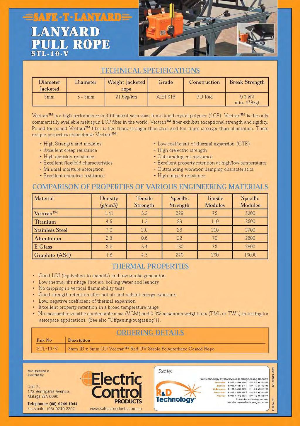
42 LANYARD PULL ROPE STL-10-V Vectran is a UV Stable Red Polyurethane coated LCP (Liquid Crystal Polymer) 3mm ID x 5mm OD multifilament melt spun yarn rope, designed and manufactured for the purpose of a lanyard emergency stop pull wire system. is designed to comply with the Machinery Standards AS Clause Actuator Colour. The actuator of the emergency stop device SHALL be coloured red. The Actuator of a Lanyard switch is the Pull Wire thus it is made in a Red UV stable Polyurethane so to with stand the harsh environments that the wires are placed in, without cracking of the cover or fading of the colour. Once the is fitted to a Lanyard Switch and run through Rope Guides and Installed as per the switch Installation Instruction, you will then make sure your site is complying to the relevant Australian or International Standards for conveyor Emergency Stops. LANYARD PULL ROPE 42 R&D Technology - Material Handling Catalogue Safe-T-Lanyard - Vectran
43 43

44 Made in Western Australia The is a highly reflective emergency stop sign for conveyor lanyard switches and pull wires. It is manufactured from a high grade 3M reflective product which a has a 10 year guarantee and is mounted to a specially designed mounting bracket which is angled to give the operator a view of the sign at all angles. The mounting bracket is made from either 1.2mm PGI metal or 1.2mm 304 Stainless Steel. With two 6mm mounting holes the bracket is simple and easy to install on existing or new installations. The angle is also designed so that when mounted as per the Australian Standards AS (every 30m) they can be seen at every 15m point. The Australian Standards AS Clause (c) state that, Signs shall be provided at each end and every 30m along a conveyor where a pull wire is used e.g. emergency stop. EMERGENCY STOP PULL WIRE SIGN 44 R&D Technology - Material Handling Catalogue Safe-T-Pull Sign
45 DIMENSIONS 30 metres EMERGENCY EMERGENCY STOP STOP EMERGENCY EMERGENCY STOP STOP 315mm 300mm 10mm ø 6.0mm hole 170mm 110mm ORDERING DETAILS Part No. Bracket Material Type Label Type STP S PGI PGI Metal (Galvanised) 3M Red with White reflective lettering STP S SS 304 Stainless Steel 3M Red with White reflective lettering Manufactured in Australia by: Unit 2, 172 Beringarra Avenue, Malaga WA 6090 Telephone: (08) Facsimile: (08) Sold by: R&D Technology Pty Ltd Specialised Engineering Products Newcastle P: F: Brisbane P: F: Wollongong P: F: Gloucester P: F: Mackay P: F: E: sales@rdtechnology.com.au website: PUB. No. STP ES 8/2006 EMERGENCY STOP PULL WIRE SIGN 45


46 Product Information Emergency Stop Pullwire Labels AUSTRALIAN MADE & OWNED STANDARDS AS CONVEYOR SAFETY REQUIREMENT Emergency Stop Pullwire labels are an essential requirement where a pullwire is in use. The Australian Standards Conveyors- Safety Requirements AS , states in section Marking and Control Devices, subsection c) that: Signs shall be provided at each end and every 30m along a conveyor where a pullwire is used e.g. emergency stop. As such, all labels supplied by R&D Technology comply with the Australian Standards and are UV stable. Traffolyte Sign Part no. stpestop-trafl abel Order code: LAB Standard Sticker Part no. stpestop-sticker Order code: LAB mm 105mm 150mm Reflective Sticker Part no. stpestop-refsticker Order code: LAB mm 105mm Traffolyte Sign Attributes The Traffolyte Sign is made from laminated impact acrylic, making it highly durable. It can be sawn, bonded and drilled as needed. Two predrilled holes are located in the top left and right hand corners, to enhance the ease of installation. The sign also has the ability to be bent which makes the attachment to rounded surfaces increasingly simple. These product attributes, along with the UV stability make the Traffolyte Sign a reliable, long lasting label for conveyors where a pullwire is used. 150mm Sticker Attributes The Emergency Stop Pullwire stickers can be easily attached to the pullwire by aligning the red line with the pullwire and simply folding the sticker in half. The stickers become increasingly useful for areas where drilling to attach a sign is not an option. Having both a standard and refl ective alternative, they are ideal for usage in both above and below ground applications. 46 R&D Technology - Material Handling Catalogue Emergency Stop Pullwire Labels


47 Product Information Emergency Stop Pullwire Labels Products associated with Emergency Pullwire labels available through R&D Technology... Products that may also be purchased are: STP MC, STD-P-VA, STR, LP04-S2 and Terminal junction boxes Lanyard Pull Wire STR AKLS Emergency Stop Pullwire Labels LWS STD-P-VA LP04-S2 Traffolyte Sign Standard Sticker Refl ective Sticker STPKIT1 Switch End of Pull Wire D-Shackle STP-HDDSS Turnbuckle STP-20SS D-Shackle STP-HDDSS Thimble STP-40SS Rope Grip STP-50SS Fixed End of Pull Wire Rope Grip STP-50SS Thimble STP-40SS D-Shackle STP-HDDSS Compensation Spring STPE60 STP-MC Typical Lanyard arrangement TURNBUCKLE STP-20SS LWS-15010GAL COMPENSATION SPRING STPE60 D SHACKLE STP-HDDSS WIRE ROPE GRIP STP-50SS WIRE ROPE THIMBLE STP-40SS 47


48 Product Information AKLS Insulated Cable Clamping Wedge Simple Design Corrosion resistant Low cost High Reliability The insulated cable clamping wedge has been engineer designed to grip and support cable used as the pull wire emergency stop on a conveyor in conjunction with the LWS wire support. The sliding design of the two clamping wedges ensures parallel movement of the wedge thus applying uniform pressure to the cable. Cables with diameters from 8.5mm to 13.5mm to be clamped securely using the AKLS. When the need arises the cable-clamping wedge can be released by simply pushing the two sliding wedges back in the wedge carrier, enabling the cable to be released from the clamping wedge. Material Wedge Carrier: One piece folded steel galvanized for corrosion protection. Hole dimensions: 65mm long x 30mm wide. Wedge: Two moulded polycarbonate sliding wedges with cable grip to ensure cable is clamped, the two wedges are fi tted to the carrier. Construction The cable wedge is constructed of two parts. The carrier and the clamp- ing wedge. The wedge is designed to clamp down on the cable diam- eters 8.5mm to 13.5 mm as tension is applied to the cable. Order code: AKLS/RD01 Standard pack quantity R&D Technology - Material Handling Catalogue AKLS clamping wedge


49 LWS Lanyard Wire Support R&D Technology s LWS System approach offering ultimate flexibility & options Flame Retardant to AS/NZS :2001 Self Lubricating Material Corrosion Resistant UV stable TYPICAL APPLICATIONS UNDERGROUND COMMUNICATIONS NON-TENSION SIGNAL LINE TENSION SYSTEM LWS11 LWS11 LWS NEW NEW 13mm Blue Leaky Feeder Cable 10mm Red Pull Cable 5mm PUR SS Lanyard Pull wire LWS Lanyard Wire Support 49


50 FEATURES & SPEC S 10mm Internal Thread LWS Design VARIOUS OPTIONS Self Lubricating Material Designed to allow lanyard wire or pull cable, to be clipped into the LWS. Once installed, the lanyard cannot be removed without intentional intervention of maintenance staff. Dont let this happen to you... LWS Material Self lubricating material & longer bearing length of the LWS carrier allows conventional PVC coated lanyard wire or pull cable to slide freely. This greatly improves the effi ciency of the system and ensures compliance with AS1755 while also extending the life of the lanyard. All threaded rods, nuts and washers are either stainless steel or galvanised for longer life. Standard lengths available are 100, 150, 200, 250 & 300mm from the centre of the wire carrier to the end of the threaded rod. Each unit is supplied fi tted with two nuts, a spring washer and a fl at washer to assist installation. Bolts are offered to allow direct mounting to the conveyor structure. Bolt lengths are 20mm to 35mm supplied in 304 Stainless Steel complete with fl at & spring washers. The LWS wire carrier is injection moulded. Moulded re-enforcement of the wire carrier and the engineered overhanging tongue allow the LWS to be mounted in any orientation without allowing the lanyard to become displaced. Injection Moulded The threaded rod has no imperfections and with the nuts and washers fi tted, the installer can be assured of correct installation and adjustment. Wire Carrier: Made from a fl ame retardant copolymer polypropylene compound providing good impact strength, rigidity and UV stability. Threaded Rod: Galvanised 10mm machine rod or 304 stainless steel are standard. Extended length rods are available at additional cost. Flame Retardant / UV Stable The LWS is made from a fl ame retardant copolymer polypropylene compound which is UV stabilized for extended outdoor weathering and is commonly used in outside applications such as stadium seating and outdoor electrical enclosures. The compound has been developed to meet the requirements of the UL 94 V-2 rating and the AS/NZS :2001 (960 0 C glow wire test) whilst providing good impact strength and rigidity. Date Stamped The LWS is designed to be mounted via metal bolts or rods to conveyor structures. The LWS is also date stamped to provide whole of life traceability. LWS11 The recent addition to the LWS system is LWS11. The LWS11 is to suit larger signal line cables for non-tension n-t systems. the larger opening on the LWS11 allows cables of 13mm nominal diameter to be installed. 50 R&D Technology - Material Handling Catalogue
 LWS-HEAD-11 MOUNTING OPTIONS LWS")

 *other sizes available on request LWS")
 GAL (Galvanised) 304SS (304 Stainless) 316SS")

 GAL (Galvanised) SS (Stainless")


51 LWS (head only) LWS-HEAD LWS with Bolt LWS BOL NEW LWS11 (head only) LWS-HEAD-11 MOUNTING OPTIONS LWS Lanyard Wire Support LWS with Threaded Rod LWS GAL LWS with Extension Bar LWS GAL BOL (Stainless Steel Bolt) Thread Size (mm) Bolt Length (mm) *other sizes available on request LWS (standard head) or LWS11 (suits large signal line cable) GAL (Galvanised) 304SS (304 Stainless) 316SS (316 Stainless) Thread Size (mm) Length (mm) From centre of carrier to end of rod. 100, 150, 200, 250, 300 *other sizes available on request LWS (standard head) or LWS11 (suits large signal line cable) GAL (Galvanised) SS (Stainless Steel) Channel Width (mm) Conveyor Frame Bracket LWS with Bracket Custom brackets are available on request Channel Length (mm) *customer specifi ed LWS (standard head) or LWS11 (suits large signal line cable) The LWS Conveyor Frame Bracket has been developed to assist in mount- ing our LWS Lanyard Wire Supports to the framework of a conveyor (where no 10mm holes are available or cannot be drilled). This provides a quick & easy attachment system for the LWS. The LWS Conveyor Frame Brackets will suit frame sections up to 130mm square. Order info: RDTCONBRKT (Bracket Only) Receive a Bonus 15L Bucket for every standard pack quantity that are orderedd 51


52 LWS Lanyard Wire Support LWS Lanyard Wire Support Lanyard Wire Support Optional Accessories Visual indicators such as reflectors and signs are available on request. LWS Estop Plate Small LWS LWS Estop Plate Large LWS LWS Reflector Red-Grn LWS R&D Technology Pty Ltd Specialised Engineering Products Newcastle P: F: Brisbane P: F: Gloucester P: F: Mackay P: F: E: sales@rdtechnology.com.au website: LWS Brochure R&D Technology - Material Handling Catalogue
 AUSTRALIAN MADE & OWNED Typical Lanyard Arrangement D-Shackle Rope Grip Lanyard Wire Rope Grip D-Shackle Safe-T-Pull Lanyard D-Shackle Turnbuckle Thimble Lanyard")

53 Product Information Safe-T-Pull Lanyard Kit Designed to suit Electric Control Product Lanyards The Lanyard kit has been designed specifi cally to suit the Safe-T-Pull and Pull-safe range of lanyards from Electric Control Products (ECP) AUSTRALIAN MADE & OWNED Typical Lanyard Arrangement D-Shackle Rope Grip Lanyard Wire Rope Grip D-Shackle Safe-T-Pull Lanyard D-Shackle Turnbuckle Thimble Lanyard Wire Support Thimble Compensation Spring Lanyard Kit Assembly Switch End of Pull Wire D-Shackle STP-HDDSS Turnbuckle STP-20SS D-Shackle STP-HDDSS Thimble STP-40SS Rope Grip STP-50SS Fixed End of Pull Wire Rope Grip STP-50SS Thimble STP-40SS D-Shackle STP-HDDSS Compensation Spring** ** STP-KIT1 uses STP-E60 matches to STP-M PS-KIT1 uses PS-60 matches to PSP-P Ordering Information STP-KIT1 (suits Safe-T-Pull) PS-KIT1 (suits Pull-Safe) Hardware components are available individually on request. Description Part No. QTY Description Part No. QTY Turnbuckle STP-20SS 2 Turnbuckle STP-20SS 1 Rope Grip STP-50SS 4 Rope Grip STP-50SS 2 Thimble STP-40SS 4 Thimble STP-40SS 2 D-Shackle STP-HDDSS 6 D-Shackle STP-HDDSS 3 Comp. Spring STP-E60 2 Comp. Spring PS-60 1 Safe-T-Pull Lanyard Kit 53


54 Product Information Thermo Tilt RTD Monitoring of conveyor dead shaft tail rollers Monitors shaft angle & temperature at the bearing on; Dead shaft tail rollers Dead shaft pulley rollers The Thermo tilt RTD brings together proven tilt switch technology and temperature monitoring via 3 wire RTD & Mercury Switch. Each unit is factory tested to confi rm operation within tolerances and is supplied with easy to understand installation instructions. GRN/YEL RED 200mm WHITE BLACK MERCURY SWITCH RED WHITE SCREEN SCREEN Specifications Casing Electronics Sealant Electrical RTD Safety Cable length Cable protection Tilt orientation Max. Temp Thread LTTRTD Stainless steel Passive device Polyurethane - Totally encapsulated 120VAC-1A resistive / 48VDC-1A resistive Class B o C, 100 o C All metal parts are bonded to the earth core in cable. Fully screened 0.5mm 2 DEKRON cable 3 metres length (standard) Stainless steel fl exible conduit 2.5 metres Contacts open approx 15 degrees from the horizontal line on case C (long term exposure limit). M12 (others available on request) Simply contact R&D Technology to obtain the product that suits you...!! Note: all information is subject to change & images are for illustration purposes only. Proudly Australian Made To suit Australian conditions R&D Technology Pty Ltd Specialised Engineering Products Newcastle P: F: Brisbane P: F: Gloucester P: F: Mackay P: F: E: sales@rdtechnology.com.au website: Thermo Tilt RTD R&D Technology - Material Handling Catalogue Thermo Tilt RTD

 200mm BLACK (2) WHITE (1) WHITE (2) MERCURY SWITCH ALARM 1 ALARM 2 Specifications Casing Electronics Sealant Electrical Operating Temp Safety Cable length Cable protection Tilt orientation")
 70 O C All metal parts are bonded to the earth core in cable. Fully screened 0.5mm 2 DEKRON cable 3 metres length (standard) Stainless steel fl exible conduit 2.")
55 Product Information Thermo Tilt Probe Switch Monitoring of conveyor dead shaft tail rollers Monitors shaft angle & temperature at the bearing on; Dead shaft tail rollers Dead shaft pulley rollers The Thermo tilt Probe switch brings together proven tilt switch technology and temperature monitoring via thermostats & Mercury Switch. Each unit is factory tested to confi rm operation within tolerances and is supplied with easy to understand installation instructions. BLACK (1) 200mm BLACK (2) WHITE (1) WHITE (2) MERCURY SWITCH ALARM 1 ALARM 2 Specifications Casing Electronics Sealant Electrical Operating Temp Safety Cable length Cable protection Tilt orientation Max. Temp Thread LTT Stainless steel Passive device Polyurethane - Totally encapsulated 24V AC/DC - 1A resistive Alarm 1: 70 O C (open +/- 5 O C, Reset (close) 50 O C Alarm 2: 90 O C (open +/- 5 O C, Reset (close) 70 O C All metal parts are bonded to the earth core in cable. Fully screened 0.5mm 2 DEKRON cable 3 metres length (standard) Stainless steel fl exible conduit 2.5 metres Contacts open approx 15 degrees from the horizontal line on case C (long term exposure limit). M12 (others available on request) Simply contact R&D Technology to obtain the product that suits you...!! Note: all information is subject to change & images are for illustration purposes only. Proudly Australian Made To suit Australian conditions R&D Technology Pty Ltd Specialised Engineering Products Newcastle P: F: Brisbane P: F: Gloucester P: F: Mackay P: F: E: sales@rdtechnology.com.au website: Thermo Tilt probe switch Thermo Tilt Probe Switch 55


56 Product Information Thermo Tilt Switch Reliable. Economical. Robust Proudly Australian Made To suit Australian conditions Note: LTT Internal Switching arrangement. Alternatives available on request Leveltec Engineering has manufactured tilt switches used throughout the Mining Industry for many decades assuring customers of not only top quality but repeatability. The Thermo tilt range brings together proven tilt switch technology and simple robust temperature switching devices to detect both over temperature and changed orientation in normally static machinery E Ø11mm 1 70 o 90 o TILT mm 50mm Ø10mm clearance 50mm Thermo tilt has as standard three individual switching outputs allowing the installer to know what fault has occurred (whether over temperature, tilt or a combination of both) and then decide what action needs to be taken. Alternative Switching arrangements available on request. Each unit is factory tested to confi rm operation within tolerances and is supplied with easy to understand installation instructions. 56 R&D Technology - Material Handling Catalogue Thermo Tilt Switch Thermo Tilt Switch - Rev B
57 Product Information Specifications LTT LTT Casing: Electronics: Sealant: Electrical: Tilt: Thermal switches: Safety: Cable length: Stainless steel Passive device Polyurethane 120VAC-1A resistive / 48VDC-1A resistive Sealed mercury switch (further encapsulated) Normally Closed (N/C) in normal conditions Sub miniature bimetal thermostat. Normally Closed (N/C) in normal conditions All metal parts are bonded to the earth core in cable. Standard cable length 3 metres (others on request) Cable protection: Stainless steel fl exible conduit 1 metre from Thermo tilt (others on request) Tilt orientation: Contacts open Approximately 15 degrees in all vertical planes and 15 degrees from top dead centre. Operating Alarm C (open +/- 5 0 C, reset (close) 30 0 C 70 0 C (Open +/-5 0 C, reset (close) 50 0 C Temperature: Alarm C (open +/- 5 0 C, reset (close) 50 0 C 90 0 C (Open +/-5 0 C, reset (close) 60 0 C Maximum temperature: C (long term exposure limit). Mounting: Horizontal or vertical via M8 or M10 bolt through centre of Thermo tilt or via M10 trough external tag mount or clamped to shaft. Mounting options for Thermo Tilt Switch 0 0 N/C N/O 15 0 N/O N/C N/O 15 0 N/O 15 0 THERMO TILT SWITCH degrees degrees Part No. LTT Sales or Technical enquiries: R&D Technology p: e: sales@rdtechnology.com.au w: Sales or Technical enquiries: R&D Technology p: e: sales@rdtechnology.com.au w: LTT Part No degrees degrees THERMO TILT SWITCH M8 or M10 Bolt (shown not supplied) Hose Clamps not supplied. Simply contact R&D Technology to obtain the product that suits you...!! Note: all information is subject to change & images are for illustration purposes only. 57

58 Product Information Snap Action Tilt Switch with Time Delay Model LP01-S2 Reliable. Economical. Robust CERTIFIED AS High bin level indication and/or control. Plugged conveyor transfer point detection. Plugged chute detection. Crusher bowl level indication and/or control. Conveyor loss of feed indication and/or control. Conveyor belt drift indication and/or alarm. Boom stackers. Radial stackers. Wiring Diagram REINFORCED CABLE ENTRY BROWN (1) WHITE (2) 300mm nominal 42mm BUILT-IN TIME DELAY EARTHED BODY ALL SWITCHES 304 STAINLESS OR CHROME PLATED 1 B.S.P INTERNAL SOCKET Shown with switch in vertical position Contact Rating Time Delay Specifications LP01-S2 24VDC - 4A (maximum 24A inrush) 250VAC - 7A BLUE (3) GREEN/YELLOW S48 30VDC (5A resistive) (3A inductive) 125VDC (0.4A resistive) (0.03A inductive) Approx. 1-2 seconds standard up to 5-6 seconds available Switch Mode Vertical brown, white closed Tilted brown, blue closed Operating Angle Approx. 20 degrees from vertical Standard Cable 3C+E, 6 metre length Temp rating 75ºC IP rating IP66/67 certifi ed to AS Standard Material Steel with chrome plated fi nish See over page for ordering information Engineered Australian quality, Leveltec ask for it by name... Snap Action Tilt Switch Information/images are subject to change without notice 58 R&D Technology - Material Handling Catalogue Snap Action Tilt Switch LP01-S2
59 Product Information Snap Action Tilt Switch LP01-S2 Ordering information Snap Action Tilt Switch LP01-S2-CH/6/S48 S48 version, VDC Switch (refer specifi cation) Standard PVC Cable lengths in metres: 6 or 10 Longer Lengths available on request. For Heavy duty cable option add HD prefi x to cable length e.g. LP01-CH/HD6 CH (Chrome plated body) or SS (304 Stainless Steel body) Cable Options PVC Cable 3C+E mm Standard Fitment on all switches Heavy Duty Cable 3C+E Steel Wire Braided - 1.0mm Order Option: HD Accessories (to be ordered separately) Wear Plate Chrome plated bisalloy plate Part No. TS-WEARPLATE-S2 Extension Tube 130mm Chrome plated tube Part No. PIPE-130MM-EXT/CHROMED Hanger & Link Chrome or SS316 hanger with quick link Part No. Chrome TS-HANGER-KIT-CH Part No. Stainless TS-HANGER-KIT-SS Simply contact Leveltec to obtain the product that suits you...!! Note: all information is subject to change & images are for illustration purposes only. Leveltec Engineering Pty Ltd Gloucester P: F: Sydney P: F: E: sales@leveltec.com.au website:
60 Model LP02-S2 Series Product Information Light Weight Tilt Switch with Time Delay Proudly Australian Made To suit Australian conditions Low Density material High bin level indication and/or control. Plugged conveyor transfer point detection. Plugged chute detection. Boom stackers. Radial stackers. REINFORCED STAINLESS STEEL CABLE ENTRY Wiring Diagram WHITE (2) BROWN (1) 300mm EARTHED METALLIC PARTS Shown with switch in vertical position BLUE (3) GREEN/YELLOW Specifications 100mm dia. PLASTIC CONSTRUCTION Contact Rating Time Delay 24VDC - 4A (maximum inrush 24A) 250VAC - 7A Approx. 1-2 seconds standard up to 5-6 seconds available Switch Mode Vertical brown, white closed Tilted brown, blue closed Operating Angle Approx. 20 degrees from vertical Standard Cable PVC 3C+E, 6 metre length Temp rating 75ºC Standard Materials Options Polyethylene, Polypropylene & Stainless Steel Plastic Float ball or Plastic Straight shaft See over page for ordering information Engineered Australian quality, Leveltec ask for it by name... Light Weight Time Delay Tilt Switch LP02-S Information/images are subject to change without notice 60 R&D Technology - Material Handling Catalogue Light Weight Tilt Switch LP02-S2
61 Product Information Light Weight Tilt Switch with Time Delay Light Weight Tilt Switch with Time Delay LP02-S2-FB-PVC/6 Ordering information Standard PVC Cable lengths in metres: 6 or 10 Longer Lengths available on request. For Heavy duty cable option add HD prefi x to cable length e.g. LP02-S2-FB-PVC/HD6 PVC FB-PVC PVC - Straight Plastic FB-PVC - Plastic Float ball Cable Options PVC Cable 3C+E mm Heavy Duty Cable Steel Wire Braided - 1.0mm Standard Fitment on all switches Order Option: HD Accessories (to be ordered separately) Hanger & Link 316 Stainless Steel hanger with link Part No. Stainless LTS Simply contact R&D Technology to obtain the product that suits you...!! Note: all information is subject to change & images are for illustration purposes only. R&D Technology Pty Ltd Specialised Engineering Products Newcastle P: F: Brisbane P: F: Gloucester P: F: Mackay P: F: E: sales@rdtechnology.com.au website:

62 Product Information Snap Action Tilt Switch with Time Delay Model LP03 Designed for use with Intrinsically Safe Circuits IS Intrinsically Safe CERTIFIED AS REINFORCED CABLE ENTRY High bin level indication and/or control. Plugged conveyor transfer point detection. Plugged chute detection. Crusher bowl level indication and/or control. Conveyor loss of feed indication and/or control. Conveyor belt drift indication and/or alarm. Boom stackers. Radial stackers. Wiring Diagram (2) (1) 300mm nominal BUILT-IN TIME DELAY EARTHED BODY ALL SWITCHES Shown with switch in vertical position Specifications (3) GREEN/YELLOW 304 STAINLESS OR CHROME PLATED 1 B.S.P INTERNAL SOCKET Contact Rating 24VDC - 4A (maximum inrush 24A) Time Delay Approx. 1-2 seconds standard up to 5-6 seconds available Switch Mode Vertical core (1), (2) closed Tilted core (1), (3) closed Operating Angle Approx. 20 degrees from vertical Switch Cable 1.5mm 2 3C+E, Blue outer sheath, 10m length Temp rating 75ºC IP rating IP66/67 certifi ed to AS Standard Material Steel with chrome plated fi nish See over page for ordering information 42mm Engineered Australian quality, Leveltec ask for it by name... Snap Action Tilt Switch LP Information/images are subject to change without notice 62 R&D Technology - Material Handling Catalogue Snap Action Tilt Switch LP03

63 Snap Action Tilt Switch LP03 Product Information Ordering information Snap Action Tilt Switch LP03-CH/IS10 IS Intrinsically Safe Standard Cable length in metres: mm 2 3C+E, Blue Coloured outer sheath for use with intrinsically safe circuits. CH (Chrome plated body) or SS (304 Stainless Steel body) Hazardous Applications: The independently tested LP03 Tilt switch can be used in hazardous areas. The tilt switch is classed as a simple device and does not contain components capable of storing or producing an electric charge. As a simple device the LP03 tilt switch can be used in hazardous applications provided it is isolated by an intrinsically safe barrier. Accessories (to be ordered separately) Wear Plate Chrome plated bisalloy plate Part No. TS-WEARPLATE-S2 BSH IS Barrier Box For hazardous applications Part No. on request Extension Tube 130mm Chrome plated tube Part No. PIPE-130MM-EXT/CHROMED Hanger & Link Chrome or SS316 hanger with link Part No. Chrome TS-HANGER-KIT-CH Part No. Stainless TS-HANGER-KIT-SS Simply contact Leveltec to obtain the product that suits you...!! Note: all information is subject to change & images are for illustration purposes only. Leveltec Engineering Pty Ltd Gloucester P: F: Sydney P: F: E: sales@leveltec.com.au website:
64 Mercury Tilt Switch Model LP04-S2 Series Product Information Proudly Australian Made To suit Australian conditions CERTIFIED AS High bin level indication and/or control. Plugged conveyor transfer point detection. Plugged chute detection. Crusher bowl level indication and/or control. Conveyor loss of feed indication and/or control. REINFORCED CABLE ENTRY Conveyor belt drift indication and/or alarm. Boom stackers. 230mm nominal EARTHED BODY ALL SWITCHES Radial stackers. Specifications LP04-S2 24 VDC - 1A / 60 VDC 0.8 AMP 110 VAC - 1.5A / 240 VAC 0.8 AMP NON INDUCTIVE 304 STAINLESS OR CHROME PLATED Switch Mode Operating Angle Standard Cable Vertical Closed Tilted Open Approx. 20 degrees from vertical PVC 2C+E 0.75mm 1 B.S.P INTERNAL SOCKET Temp rating 75ºC IP rating IP66/67 certifi ed to AS mm Standard Material Steel with chrome plated fi nish See over page for ordering information Engineered Australian quality, Leveltec ask for it by name... Mercury Tilt Switch LP04-S Information/images are subject to change without notice 64 R&D Technology - Material Handling Catalogue Mercury Tilt Switch LP04-S2
65 Product Information Mercury Tilt Switch LP04-S2 Mercury Tilt Switch LP04-S2-CH/6 Ordering information Standard PVC Cable lengths in metres: 6 or 10 Longer Lengths available on request. For Heavy duty cable option add HD prefi x to cable length e.g. LP04-S2-CH/HD6 CH (Chrome plated body) or SS (304 Stainless Steel body) Cable Options PVC Cable 2C+E mm Standard Fitment on all switches Heavy Duty Cable Steel Wire Braided - 1.0mm Order Option: HD Accessories (to be ordered separately) Wear Plate Chrome plated bisalloy plate Part No. TS-WEARPLATE-S2 Extension Tube 130mm Chrome plated tube Part No. PIPE-130MM-EXT/CHROMED Hanger & Link Chrome or SS316 hanger with link Part No. Chrome TS-HANGER-KIT-CH Part No. Stainless TS-HANGER-KIT-SS Simply contact Leveltec to obtain the product that suits you...!! Note: all information is subject to change & images are for illustration purposes only. Leveltec Engineering Pty Ltd Gloucester P: F: Sydney P: F: E: sales@leveltec.com.au website:

66 Product Information Mercury Tilt Switch Model LP04-R Series Reliable. Economical. Robust High bin level indication and/or control. Plugged conveyor transfer point detection. CERTIFIED AS Plugged chute detection. Crusher bowl level indication and/or control. Conveyor loss of feed indication and/or control. Conveyor belt drift indication and/or alarm. Boom stackers. Radial stackers. REINFORCED CABLE ENTRY Specifications 230mm nominal EARTHED BODY ALL SWITCHES Electrical Ratings (All Non Inductive) Switch Mode LP04-R LP04-RA 24 VDC - 1.0A / 60 VDC 0.8 AMP 24 VDC AMP 110 VAC - 1.5A / 240 VAC 0.8 AMP Vertical Closed Tilted Open Operating Angle Approx. 20 degrees from vertical 304 STAINLESS OR CHROME PLATED 3/4 B.S.P INTERNAL SOCKET Temp rating 75ºC IP rating Cable Material Cable Length Standard Material IP66/67 certifi ed to AS PVC 2C+E or PVC 2C+E Steel wire braided Chrome plated 6 or 10 metres Stainless steel or chrome plated See over page for ordering information 42mm Engineered Australian quality, Leveltec ask for it by name... Mercury Tilt Switch LP04-R Information/images are subject to change without notice 66 R&D Technology - Material Handling Catalogue Mercury Tilt Switch LP04-R
67 Product Information Mercury Tilt Switch LP04-R Mercury Tilt Switch LP04-R-CH/6 Ordering information Standard PVC Cable lengths in metres: 6 or 10 Longer Lengths available on request. For Heavy duty cable option (RA version only) add HD prefi x to cable length e.g. LP04-RA-CH/HD10 CH (Chrome plated body) or SS (304 Stainless Steel body) (RA version only) R 24VDC - 1.0A Equivalent to ( ) & ( ) RA 24VDC - 1.0A / 60 VDC 0.8A 110VAC - 1.5A / 240VAC 0.8A Equivalent to ( ) Cable Options PVC Cable 2C+E mm Standard Fitment on all switches Heavy Duty Cable 2C+E Steel Wire Braided - 1.0mm available on RA version only Order Option: HD Accessories (order separately) Hanger & Link Chrome or 316 Stainless Steel hanger with link Part No. Chrome TS-HANGER-KIT-CH Part No. Stainless TS-HANGER-KIT-SS Simply contact Leveltec to obtain the product that suits you...!! Note: all information is subject to change & images are for illustration purposes only. Leveltec Engineering Pty Ltd Gloucester P: F: Sydney P: F: E: sales@leveltec.com.au website:

68 Model LP05-S2 Series Product Information Light Weight Mercury Tilt Switch Proudly Australian Made To suit Australian conditions Low Density material High bin level indication and/or control. REINFORCED STAINLESS STEEL CABLE ENTRY Plugged conveyor transfer point detection. Plugged chute detection. Boom stackers. Radial stackers. 300mm EARTHED METALLIC PARTS LP05-S2 Specifications 24 VDC - 1A / 60 VDC 0.8 AMP 110 VAC - 1.5A / 240 VAC 0.8 AMP NON INDUCTIVE PLASTIC CONSTRUCTION Switch Mode Operating Angle Vertical Closed Tilted Open Approx. 20 degrees from vertical Standard Cable PVC 2C+E 0.75mm Temp rating 75ºC Standard Materials Options Polyethylene, Polypropylene & Stainless Steel Plastic Float ball or Plastic Straight shaft 100mm dia. See over page for ordering information Engineered Australian quality, Leveltec ask for it by name... Light Weight Mercury Tilt Switch LP05-S Information/images are subject to change without notice 68 R&D Technology - Material Handling Catalogue Light Weight Tilt Switch LP05-S2
69 Product Information Light Weight Mercury Tilt Switch Ordering information Light Weight Mercury Tilt Switch LP05-S2-FB-PVC/6 Standard PVC Cable lengths in metres: 6 or 10 Longer Lengths available on request. For Heavy duty cable option add HD prefi x to cable length e.g. LP05-S2-FB-PVC/HD6 PVC FB-PVC PVC - Straight Plastic FB-PVC - Plastic Float ball Cable Options PVC Cable 2C+E mm Heavy Duty Cable Steel Wire Braided - 1.0mm Standard Fitment on all switches Order Option: HD Accessories (to be ordered separately) Hanger & Link 316 Stainless Steel hanger with link Part No. Stainless LTS Simply contact R&D Technology to obtain the product that suits you...!! Note: all information is subject to change & images are for illustration purposes only. R&D Technology Pty Ltd Specialised Engineering Products Newcastle P: F: Brisbane P: F: Gloucester P: F: Mackay P: F: E: sales@rdtechnology.com.au website:

70 Product Information Heavy Duty Float Switch FT-1000 Range The FT-1000 consists of a heavy duty polypropylene fl oat double moulded onto a high quality three core cable. The fl oat contains a single pole double throw switch, which can be used to give adjustable control over the level of liquid in tanks, pits and dams. By careful tethering of the cable the switch can be set to give an on or off action at any desired position. The heavy duty switch can directly control small pump motors, and is also ideal for instrument or PLC signalling Features Extra strong polypropylene fl oat S.P.D.T three wire switch No mercury or lead components High quality rubber cable No corrodible metal parts Sealed tamperproof design Highly chemical resistant Wide range of cable lengths available Optional cable weight available Cable Data APPLICATIONS Applications High and low level control in tanks, pits and dams Loss of prime protection for pumps Automatic control of sump pumps Control of tank fi lling and draining valves Control of levels in effl uent and separation pits Level control in bulk liquid tanks Control of level warning equipment Important Safety Notice The switch is made of high grade polypropylene. Our high tech manufacturing process produces a sealed, seamless and glandless fl oat that is totally tamperproof and extremely tough. The heavy duty cable fi tted to the FT-1000 switch is constructed from Hypalon rubber, which is specifi - cally designed for permanent immersion in water. The switch and cable are also resistant to oil, grease, fat, sewerage and a variety of chemicals. Plan View 180mm 10mm dia. Cable The FT-1000 switches have been designed and built to be as tough as possible, and can withstand harsh environments. Great care should be taken to ensure that the switch is only installed in positions where it will not be subjected to entanglement, severe agitation and abrasion against tank walls or moving equipment. If the application requires control of mains voltage, local electrical codes my require the switch to be isolated at a low voltage supply. This may be required, regardless of the high voltage rating of the fl oat switch. Please check with your local Electrical authority before connection the FT-1000 to a mains voltage supply. 56mm Side View NSW DEPARTMENT OF MINERALS AND ENERGY APPROVAL NUMBER CS4937N 70 R&D Technology - Material Handling Catalogue FT-1000 H.Duty Float Switch 180mm FT-1000 Range brochure
71 FT-1000 Range Cable type Outer sheathing Inner sheathing Cores Cable diameter Core colours Cable voltage rating Uo/U AC test voltage Cable current carrying capacity CABLE SPECIFICATIONS Product Information Heavy duty EPR/CSP Flexible Hypalon Rubber CSP Hypalon, Oil Resistant & Flame Retarded to VDE 0472 R-EP-90 Special Elastomer Insulation 3 Cores, each 1.2mm diameter 10mm Nominal Blue (Common) Black (Normally Closed) Brown (Normally Open) 600V/1kV 2.5kV Cable maximum tensile strength 15 N/mm 2 Minimum bending radii Maximum ambient Operating temperature Minimum permissible ambient temperature Minimum permissible ambient temperature for fully flexible operation Cable maximum permissible short circuit temperature Standards of cable construction Cable lengths available 350mm Maximum Switching range adjustable up to a maximum of 350mm depending on tethering point. PART NUMBER CREATION Below is an example of how to create a part number for the FT-1000 fl oat switch, using the stocked cable length of 15m Model FT Serial Number Cable Length (in metres) 18 Amps Continuous at a Temperature of 30.5ºC 50mm 80ºC -40ºC -25ºC 250ºC Meets or exceeds AS1125, AS3191, AS3116 and DIN/VDE0282 1, 3, 4, 6, 10, 15, 20, 30, 50 Metres standard. Against special order switches to 1000 Metres can be supplied TYPICAL INSTALLATION Normally Closed (Black Wire) Common (Blue Wire) Normally Open (Brown Wire) 3 WIRE SINGLE POLE DOUBLE THROW SWITCH Normally Closed (Black Wire) Common (Blue Wire) Normally Open (Brown Wire) OPTIONAL CABLE WEIGHT Below is the part number of the stocked optional cable weight FT-1000-W Optional Cable weight Maximum submergence Switch type Contact gap Contact material Contact resistance Rated voltage AC Rated voltage DC Current rating AC resistive Motor load current rating AC Current rating DC resistive Maximum lamp load AC Maximum lamp load DC Maximum operating frequency, electrical Insulation resistance Dielectric strength between contacts Life expectancy mechanical Life expectancy electrical Approved standards ENVIRONMENTAL LIMITATIONS Maximum liquid temperature 60ºC Minimum liquid temperature SWITCH SPECIFICATIONS Single pole double throw Simply contact R&D Technology to obtain the product that suits you...!! Note: all information is subject to change & images are for illustration purposes only. 1mm Silver alloy 15 milli Ohms (max) 0 to 240V AC 0 to 250V DC 21 A at 250V 4 A at 250V 0.3 Amps at 250V 3 Amps at 250V 30meters, 300kPa static pressure -20ºC Liquid specific gravity >0.82 Liquid Ph 1 to 14 Smallest diameter well that the switch can operate in Liquid level change for switch to operate Smallest opening through which the switch will fit Minimum distance between float and closest tethering point or cable weight Suitability for use in diesel fuel Suitability for use in sodium hypochlorite Suitability for sea water use Suitability for use in octane (petrol) Suitability for use in potable water 600mm 350mm (approx.) 108mm diameter 150mm Can be used, but some swelling and softening of the cable and boot may occur Fully compatible Fully compatible Not suitable Fully compatible 0.05 Amps at 250V 60 operations per minute 100M Ohms minimum at 500 V DC 1000 V AC at 50 to 60Hz for 1 minute 50,000,000 operations minimum 100,000 operations minimum UL508 E41515, CSA C22.2 No.55 (File No LR21642) R&D Technology Pty Ltd Specialised Engineering Products Newcastle P: F: Brisbane P: F: Gloucester P: F: Mackay P: F: E: sales@rdtechnology.com.au website:

72 Product Information Float Switch FT-2000 Range The FT-2000 is a compact three-wire fl oat switch for highly accurate ate and repeatable single point level sensing and control applications. It is ideal for use in water, sea water and most acids and alkali solutions. It will provide a stable switching action with a very high degree e of reliability. The teardrop shape of the fl oat makes it ideal for effl uent and sewage usage, as the fl oat cell has no shoulders or edges for solids to build on. Features APPLICATIONS Applications BLACK BLUE BROWN Low differential switching All direction tilt action S.P.D.T 3 wire single point switch Polypropylene & hypalon construction Wide range of cable lengths available Stable repeatable switching action No mercury or lead components Compact size (75mm diameter) Optional cable weight available Basic liquid level control Multi point level control Sewerage level control Chemical level controls High & low level alarms Self powered signalling Pump protection Potable water systems 109mm 75mm 150mm min. Operating Principle The FT-2000 houses a heavy ball that is balanced on the actuating arm of a high precision switch. When rising liquid causes the fl oat to lift and tilt, the centre of gravity of the ball moves away from the actuating axis of the switch and allows it to de-actuate. A falling liquid level allows that fl oat to straighten up and the centre of gravity of the ball shifts back onto the switch causing it to again actuate. This simple reliable action only requires the fl oat to tilt by 45 degrees in any direction for the switch to operate. Important Safety Notice The FT-2000 level regulators are rated for mains voltage operation. However, in the interest of safety we recommend that they are only ever operated at low voltage, preferably at 24 to 48V AC. Where mains voltage operation is unavoidable an earth leakage circuit breaker should always be installed in the control circuit. The application and wiring of this fl oat switch should always be carried out by a qualifi ed electrical personnel and must always conform to local wiring rules. Construction The fl oat chamber is a double moulded hermetically sealed cell with a double moulded barrier of solid polypropylene sealing the cable entry. The switch housed within the fl oat cell is a precision single pole double throw device rated at 0 to 240V AC at up to 15 Amps resistive load. Hazardous Applications This level regulator is classed as a simple device and does not require separate certifi cation to be used in hazardous applications. In any such installation the level regulator should be isolated by an intrinsically safe barrier, a zener barrier. FT-2000 Range brochure R&D Technology - Material Handling Catalogue FT-2000 H.Duty Float Switch
73 FT-2000 Range Product Information Blue Cable type Outer sheathing Inner sheathing Cores Cable diameter Core colours Cable voltage rating Uo/U AC test voltage Cable current carrying capacity Cable maximum tensile strength Minimum bending radii Maximum ambient Operating temperature Minimum permissible ambient temperature Minimum permissible ambient temperature for fully flexible operation Cable maximum permissible short circuit temperature Standards of cable construction Cable lengths available Pump Float Vertical Black Brown TYPICAL INSTALLATION High Level Float Switch Low Level Float Switch OPERATION 35mm CABLE SPECIFICATIONS High Water Level Pumping Range with 2 fl oat switches Low Water Level Float Tilted Blue Heavy duty EPR/CSP Flexible Hypalon Rubber CSP Hypalon, Oil Resistant & Flame Retarded to VDE 0472 R-EP-90 Special Elastomer Insulation 3 Cores, each 0.75mm Sq. tinned copper 7.5mm Nominal Blue (Common) Black (Normally Closed) Brown (Normally Open) 600V/1kV 2.5kV 18 Amps Continuous at a Temperature of 30.5ºC 30 N 40mm 80ºC -40ºC -25ºC 250ºC Meets or exceeds AS1125, AS3191, AS3116 and DIN/VDE0282 1, 3, 4, 6, 10, 15, 20, 30, 50 Metres standard. Against special order switches to 1000 Metres can be supplied Black Brown PART NUMBER CREATION Below is an example of how to create a part number for the FT-2000 fl oat switch, using the stocked cable length of 15m Model FT Serial Number Cable Length (in metres) OPTIONAL CABLE WEIGHT Below is the part number of the stocked optional cable weight FT-2000-W Optional Cable weight Maximum submergence Switch type Contact gap Contact material Contact resistance Rated voltage AC Rated voltage DC Current rating AC resistive Motor load current rating AC Current rating DC resistive Maximum lamp load AC Maximum lamp load DC Minimum operating load Maximum operating frequency, electrical Insulation resistance Dielectric strength between contacts Life expectancy mechanical Life expectancy electrical Approved standards ENVIRONMENTAL LIMITATIONS Maximum liquid temperature 60ºC Minimum liquid temperature SWITCH SPECIFICATIONS Single pole double throw 0.5mm Silver alloy 15 milli Ohms (initial value) 0 to 240V AC 0 to 250V DC 30meters, 300kPa static pressure -20ºC Liquid specific gravity >0.82 Liquid Ph 1 to 14 Smallest diameter well that the switch can operate in Liquid level change for switch to operate Closest switching point to tank floor Smallest opening through which the switch will fit Minimum distance between float and closest tethering point or cable weight Suitability for use in diesel fuel Suitability for use in sodium hypochlorite Suitability for sea water use Suitability for use in octane (petrol) Suitability for use in potable water Within a 160mm inside diameter vertically mounted pipe 35mm 50mm 75mm diameter 150mm Can be used, but some swelling and softening of the cable and boot may occur Fully compatible Fully compatible Not suitable Fully compatible 15 A at 250V AC, 15A at 125V DC 1.5 A at 250V AC, 2.5A at 125V AC (1/4 HP) 15 Amps at 14V DC, 6 Amps at 30V DC 1.25 Amps at 250V AC 1.5 Amps at 30V DC 100mA at 12V, or 60mA at 24V 24 operations per minute 100M Ohms minimum at 500 V DC 1000 V AC at 50 to 60Hz for 1 minute 20,000,000 operations minimum 500,000 operations minimum UL508 E41515, CSA C22.2 No.55 (File No LR21642) Simply contact R&D Technology to obtain the product that suits you...!! Note: all information is subject to change & images are for illustration purposes only. R&D Technology Pty Ltd Specialised Engineering Products Newcastle P: F: Brisbane P: F: Gloucester P: F: Mackay P: F: E: sales@rdtechnology.com.au website:

 Height (mm) Weight (kg) 11W-030 584 279 381 16 Cable Bun Cable Bun Features Cable Bun Order Codes: Provides high voltage power cable suspension Lightweight, easy to handle & highly visible Made")
74 Product Information Cable Accessories Engineered for maximum protection when hoisting cables! Rope Brake Both the Rope Brake and Cable Bun are readily available and when used in conjunction provide maximum safety for your suspension needs. Rope Brake Features Rope Brake Order Code: Self-braking for maximum safety Design meets industry requirements Maintenance free and never wears out Ropebrake Order Code Dimensions Length (mm) Width (mm) Height (mm) Weight (kg) 11W Cable Bun Cable Bun Features Cable Bun Order Codes: Provides high voltage power cable suspension Lightweight, easy to handle & highly visible Made from strong & fl exible polyurethane Partnered with a two ply latex treated web sling Cable Diameter (mm) Weight (kg) Length (mm) Pennant Colour* Choker Capacity (kg) Cable Bun Order Code Sling Order Code Green 2041 CB-101 CRS Orange 2041 CB-102 CRS Blue 2041 CB-103 CRS Pink 2041 CB-104 CRS Red 2041 CB-105 CRS Yellow 2041 CB-106 CRS CB-107 CRS Green/Yellow 3447 CB-108 CRS-108 * Cable buns are supplied with colour coded pennants sewn into the sling for easy visual identifi cation. 74 R&D Technology - Material Handling Catalogue Cable Accessories


75 Product Information Cable Accessories Strain Relief Entrance fitting The strain relief entrance fi tting combines a watertight seal with a positive clamping action around the cable. It is ideal for permanent entry of a cable into a mine power center, switch gear, disconnect switch or standard terminating box. These fi ttings are available in sizes from 0.82 to 3.5 (21-89 mm) outside diameter. Note: Clamp and seal kit specifi c to the cable outside diameter must be ordered separately. Strain Relief Clamp System Cable Riser Brackets Patton & Cooke cable riser brackets attach insulated cable, conduit or piping to walls, roofs, and poles. The brackets keep the cable rigidly held in place. Available in a variety of combinations and sizes; low and high profi le mounting brackets for one or three cables. J-Hook Cable Handling Tool Introducing the new Patton and Cooke Cable Handling Tool. STRAIN RELIEF CLAMP STRAIN RELIEF CLAMP SHOWN INSTALLED ON TRAILING CABLE The strain relief clamp is designed to prevent cable jacket damage and to withstand the tough use typical in mining, construction and utility applications. Eliminates strain on the cable connections at the coupler/enclosure interface on electric shovels, drills, LHD s, jumbos, junction boxes or cable supports. Supports a cable in vertical shaft and pole suspension applications. Corrosion resistant with galvanized hardware and wire rope The strain relief clamp covers a cable diameter range of (16-92 mm). Larger sizes are available on request. Split Strain Relief Entrance Fitting With an electrostatically applied powder coating and a PVC shaft with fi berglass back bone this tool is a handsome addition to any cable handlers arsenal. Highly resilient polyester powder coating ensures longer life in extreme mining environments. Benefits: Helps protect fi berglass core from bruises and abrasions High strength, light weight Good electrical isolation with proper care and maintenance Optimal length to reduce operator back strain Corrosion resistant Fork curvature allows for easy cable pick up Heat shrink cover and retention Solid Fiberglass core 28 inch tool length Powder coated steel twist fork Outside Cable Diameter Patton & Cooke (mm) (in) Catalog Number W-040-D-U W-040-D-V W-040-D-W W-040-D-X W-040-D-Y W-040-D-Z The split strain relief entrance fi tting is ideally suited for installations where trailing cable couplers are not being used, but where cables may be installed and removed frequently. The split design means that the entrance fi tting can be installed or removed without disturbing the stress cones, sleeves or taping which makes up the cable termination. Cables can be installed and removed quickly. The strain relief entrance fi tting is tightened to provide a positive clamp on the cable. No tools are required. Available in sizes which cover cable outside diameters from 2.76 to 3.50 ( 70 to 89 mm). 75


76 Viking Nut Engineered roof suspension hook...! Product Information 110kg Hook SWL* 170kg Centre Hole SWL* M24 Features Certifi ed safe working load limits that use a minimum 8:1 factor of safety The hook combines 2 traditional products into 1 Exceptional manufacturing & testing quality Low purchase price Detailed product design Ease of installation & recovery Will not rust or seize onto roof bolt thread Ease of Installation & Recovery The roof suspension hook incorporates a moulded hexagon profi le to allow the unit to be installed and recovered from ground level using a standard M24 roof bolt. The hook is simply placed onto the head of the bolt and screwed onto a roof bolt, allowing rows of hooks to be preinstalled without the use of diesel vehicles. The hooks can also be recovered using a roof bolt in a similar fashion. The roof suspension hook further lends itself to being recovered by being manufactured from bright yellow material (for improved visibility) and from a high strength material that will not rust or seize onto the roof bolt thread. Have you considered strapping your nuts? Testing & Certification The safe working loads have been determined by extensive design and independent testing, including fi - nite element analysis and independent testing and certifi cation. Ongoing production testing is conducted for every production run to ensure all units meet the minimum Safe Working Load (SWL) requirements. * SWL have been determined by loading of hooks or centre hole (i.e. not a combination of hook and centre hole) Manufacturing and Testing Quality The roof suspension hooks are manufactured using premium grade Nylon 6 which has a high tensile strength. Strap Order Codes Straps available as an optional extra include: 450mm Strap: RSH mm Strap: RSH mm Strap: RSH R&D Technology - Material Handling Catalogue Viking Nut


77 Yodalarm Sounders & Strobes... Product Information DC & AC types standard supply voltages covered by 3 varieties 3 wired polarised or 2 wire bi-polar DC second stage control on all types. 3-wire AC second stage control on YO5, YL5 and YO3 types Complies with BS : 1980 Clause 9.5 Flame Resistant ABS Plastic Enclosure Choice of lens colour (except YO3) 32 sound signals 2 Stage Alarm YO3 YO5 YL5 YO8/YO8 SUPER YL8/YL8 SUPER A 118mm 169mm 169mm 269mm 269mm B 102mm 153mm 153mm 250mm 250mm C 89mm 134mm 134mm 216mm 216mm D 85mm 128mm 128mm 153mm 153mm E 8mm 9.5mm 9.5mm 11mm 11mm F 6mm 8mm 8mm 8mm 8mm G mm mm H mm - 88mm YO3 YO5 YL5 Y08 Y08 SUPER YL8 YL8 SUPER Supply Voltages 12, 24, 48V DC +/-10% 110, 120, 240V AC +/-10% Ambient Temp Operating -25 to C Storage -40 to 70 0 C Relative Humidity 40 0 C Sound 1metre 100dB* 110dB* 110dB* 116dB 120dB 116dB 120dB Mounting The alarms may be simply installed in any place by fi xing to any suitable surface via the case lugs Ratings The alarms are electrically continuously rated. The standard Dimensions versions (mm) are weather protected to IP54. IP65 protection is available to order. Line Integrity For 3-wire 2 stage alarm systems, line integrity may be monitored via reverse polarity. For 2-wire 2 stage alarm systems, by threshold monitoring, applied voltage <IV Maintenance No regular maintenance is required. Operation of the alarm should be checked via the site system test routine. Lens Colour option Red, Amber, green, blue, opal, clear Simply contact R&D Technology to obtain the product that suits you...!! *12Vdc versions will produce approx 6dB less output Note: all information is subject to change & images are for illustration purposes only. Sounders & Strobes 77
any other M6 hole. The Tether Point Wire is approximately 1m STR- SSB- (1, 2, 3, 4, 5 or 6) -TP
 -TP") 1 Electric Control Products: Preferred Setup Instructions Note: The correct Belt Rip pick up detachment operation of the Rip Socket, is in a sideways motion to the attachment point. This means once the
1 Electric Control Products: Preferred Setup Instructions Note: The correct Belt Rip pick up detachment operation of the Rip Socket, is in a sideways motion to the attachment point. This means once the
Installation Instructions - K-Safe-T-Rip Belt Rip Detector
 Kinder Australia product: Preferred Setup Instructions Note: The correct Belt Rip pick up detachment operation of the Rip Socket, is in a sideways motion to the attachment point. This means once the Socket
MICRO SWITCH INSTALLATION SHEET
 MICRO SWITCH INSTALLATION SHEET Micro Switch Cam Rest Position See Vertical or Horizontal Arm Installation Instructions for Micro Switch activation sequence. Micro Switch Cam Adjustment Screw SW 1 Micro
ROPE THIMBLE P/N STP-40-SS P/N STP-50-SS PULL WIRE SHOULD BE STRAIGHT AND CLEAR OF OBSTRUCTIONS WIRE SUPPORT P/N STG-200, STG-200-SS
 1 P/N: PS-P INSTALLATION & SETTING INSTRUCTIONS YELLOW INDICATION FLAG: P/N STP-F The Indication Flag should be fitted when there is more than one switch used on the conveyor as noted in AS1755-2000 Clause
Installation Instructions: K-Safe-T-Drift
 Micro Switch Installation Sheet Micro Switch Cam Rest Position See Vertical or Horizontal Arm Installation Instructions for Micro Switch activation sequence. Micro Switch Cam Adjustment Screw SW 1 Micro
Cable (Rope) Pull Switches Lifeline 4
 Pull Switches Lifeline 4") Emergency Stop Devices Description The cable/push button operated system can be installed along or around awkward machinery such as conveyors and provide a constant emergency stop access. The is the only
Emergency Stop Devices Description The cable/push button operated system can be installed along or around awkward machinery such as conveyors and provide a constant emergency stop access. The is the only
LK Position Switches TECHNICAL DATASHEET.
 LK Position Switches Technopolymer housing, one conduit entry Protection degree IP6 according to EN 60529 contact blocks available 46 actuators available Versions with stainless steel external parts Versions
Safety rope switches with reset for emergency stop
 Safety rope switches with reset for emergency stop Selection diagram 8 8 83 ACTUATORS ACTUATORS CONTACT BLOCKS 18 9 21 1NO+ FP FD FL FC 22 33 34 LED signalling light CONDUIT ENTRIES For other available
Integral E-stop the lid-mounted E-stop button provides emergency stopping capability at the extreme end of the installation
 C R US Conforms to EN418, EN292, ISO/IEC1850, EN0947-5-1 UL and C-UL listed ER019 Combination Rope and Push-Button Actuated Emergency Stop Switch Long rope spans of up to 75 m (24 ft.) for standard model
FL series position switches
 FL series position switches Selection diagram 0 08 0 9 0 0 0 Ball Ø. External rubber Ball Ø 8 mm, mm, stainless Glass fibre rod gasket stainless steel steel Adjustable lever Adjustable safety lever Bistable
Miniature microswitches - Positive break
 1 Miniature microswitches - Positive break 81607 Coil spring snap-action mechanism with wiping contacts Positive opening action according to IEC 6097-5-1 Annex K atings from 10 ma Vc to 6 A 250 Va Very
Miniaturized limit switches
 Miniaturized limit switches Selection diagram Actuators 04 0 06 Thermoplastic Bodies M3 Contact blocks NONC 1NO+1NC snap action Cable entry With screw 290 GENERAL CATALOGUE miniaturized limit switches
Microswitches MK series
 Microswitches MK series Microswitches of MK series have been developed in order to add new features to traditional and tested microswitches of Pizzato Elettrica. These products have been designed with
Position switches FR series
 Position switches FR series Selection diagram 0 A 08 0-0 A A 0 A external rubber gasket external rubber gasket for electrical panels external rubber gasket external rubber gasket external rubber gasket
Microswitches MK series
 D Microswitches MK series Introduction Microswitches of MK series have been developed in order to add new features to traditional and tested microswitches of Pizzato Elettrica (cross-reference at page
Model Number Structure
 Small Sealed Switch D4E-@N Slim and Compact Switch with Better Seal and Ensuring Longer Service Life than D4E Flat springs with an improved lever ratio of the built-in switch ensure smooth snap action
Position switches FR series
 Position switches FR series Selection diagram 01 A1 08 14 01-7 0 A 05 A5 external rubber gasket external rubber gasket for electrical panels external rubber gasket external rubber gasket 0 1 5 34 50 33
D2SW-AQ. Sealed Subminiature Basic Switch Conforming to IP67 (Excluding the terminals on terminal models) Model Number Legend
 Model Number Legend") Sealed Subminiature Basic Switch Conforming to IP67 (Excluding the terminals on terminal ) Use of epoxy resin assures stable sealing, making this switch ideal for places subject to water spray or excessive
Sealed Subminiature Basic Switch Conforming to IP67 (Excluding the terminals on terminal ) Use of epoxy resin assures stable sealing, making this switch ideal for places subject to water spray or excessive
Safety rope switch with reset for emergency stop
 Safety rope switch with reset for emergency stop Selection diagram 8 8 83 ACTUATORS ACTUATORS CONTACT BLOCKS 18 9 21 1NO+,, FP FD FL FC 22 33 34,, CONDUIT ENTRIES Threaded conduit entries (standard) With
Microswitches MK Series
 General purpose microswitches for heavier duty applications High precision snap action mechanism 16A 250V AC resistive rating (I th ) Wide range of actuator styles Screw terminals with self lifting plate
Limit Switch - Prewired Type Metal Body
 Limit Switch - Prewired Type Metal Body Sealed with epoxy resin al the base of the box Degree of protection IP67 Thermoplastic material or diecast zinc alloy body Positive Opening Operation Minimum Actuation
Safety rope switch without reset for simple stop
 afety rope switch without reset for simple stop election diagram FP 4-M2 FD 4-M2 FL 4-M2 FR 4-M2 FM 4-M2 FX 4-M2 FZ 4-M2 ACTUATOR 9 ACTUATOR 9 0 CONTACT BLOCK 1 9 21 1NO+ FP FD FL FC 33 34 CONDUIT ENTRIE
Position switches FC series
 A Position switches FC series Selection diagram 0 08 8 9 0 0 0 Ø 8 mm Ø, mm external rubber stainless steel stainless steel fiber glass rod gasket sphere sphere 6 adjustable lever safety adjustable lever
Safety switches for hinged doors
 4 Safety switches for hinged doors Selection diagram FR FM FX FZ FK 5 18 7 9 snap action overlapped CONTACT BLOCKS 20 21 22 33 34 1NO+ CONDUIT ENTRIES Threaded conduit entries (standard) With cable gland
ED SERIES SAFETY LIMIT SWITCH
 Description The ED series safety limit switches conform to EN 547 and have been developed to provide a range of options including plastic cases in various sizes, a choice of snap acting, slow break/make
Position switches FD series
 Position switches FD series Selection diagram 01 08 11 18 19 02 04 05 Ø 8 mm Ø, mm external rubber stainless steel stainless steel fibber glass rod gasket sphere sphere 51 52 5 56 41 42 adjustable lever
Compact plastic limit switches with positive opening mechanism
 Compact limit switches with positive opening mechanism LJK-N Series Positive opening mechanism Positive opening mechanism meets standards worldwide. A wide variety of actuators is available. The LJK-N
CTX 3 Control relays Cat. N (s) : /06/09..14/16/19..24/26/29
 : /06/09..14/16/19..24/26/29") 87045 LIMOGES Cedex Telephone: +33 5 55 06 87 87 FAX: +33 5 55 06 88 88 CTX 3 Control relays Cat. N (s) : 4 168 00..04/06/09..14/16/19..24/26/29 CONTENTS PAGES 1. Description - Use... 1 2. Range... 1 3.
87045 LIMOGES Cedex Telephone: +33 5 55 06 87 87 FAX: +33 5 55 06 88 88 CTX 3 Control relays Cat. N (s) : 4 168 00..04/06/09..14/16/19..24/26/29 CONTENTS PAGES 1. Description - Use... 1 2. Range... 1 3.
S826, S926 Series Dual changeover switches with positive opening operation and wiping contacts Catalogue D26.en
 2 Snap-action switches S826, S26 Series Dual changeover switches with positive opening operation and wiping contacts Catalogue D26.en 2 Snap-action switches S826 Series Dual changeover switches with positive
Limit Switches - Limit Type (PS42L) Plastic Body IP65
 Plastic Body IP65") Limit Switches - Limit Type (PS42L) Plastic Body IP65 Double Insulation Degree of protection IP65 Reinforced UL-V thermoplastic fiber-glass body Positive Opening Operation Minimum Actuation Force/Torque
Limit Switches - Limit Type (PS42L) Plastic Body IP65 Double Insulation Degree of protection IP65 Reinforced UL-V thermoplastic fiber-glass body Positive Opening Operation Minimum Actuation Force/Torque
Switches with manual reset
 Switches with manual reset Selection diagram 01-W 02-W 05-W 0-W -W -H0W 16-W 16-H0W Ø mm roller Ø mm roller Ø mm roller Ø mm roller 0-W 1-W 51-W 52-W 5-W 55-W -W adjustable lever safety adjustable lever
Free Fall Fire Valve Range & Accessories
 Free Fall Fire Valve Range & Accessories 1 Contents Screwed Free Fall Fire Valves... 3 Flanged Free Fall Fire Valves... 6 Free Fall Valve Accessories... 8 Fitting Kits... 8 Mercury and Non-Mercury Switches...
Limit Switches - Limit Type Plastic Body IP65
 Limit Switches - Limit Type Plastic Body IP65 Double Insulation Degree of protection IP65 Reinforced UL-V thermoplastic fiber-glass body Positive Opening Operation Minimum Actuation Force/Torque Minimum
S840, S845, S846 Series Single-break changeover, NC or NO contacts, positive opening operation and wiping action Catalogue D40.en
 Snap-action switches S80, S85, S86 Series Single-break changeover, NC or NO contacts, positive opening operation and wiping action Catalogue D0.en Snap-action switches, S80, S85, S86 Series Single-break
Mechanical Min. 20 million operations. Min. 2 million operations for the Model SL1-B. Min. 2 million operations for high oil. (All values assume overt
 PHOTOELECTRIC & KEY COMPACT HORIZONTAL (RUGGED) Model SL1- C The C-spring material is a high-cobalt alloy, which enhances resistance to coolants. The shape of the diaphragm seal has been modified to prevent
SL1Series. Compact Horizontal Limit Switches
 Compact Horizontal Limit Switches SL1Series Mechanical life of 0 million operations. Robust long-life and maintenance-free compact horizontal-type limit switches with IP67 seal. Mechanical life exceeds
7 Lighting Technology
 7 Lighting Technology Light Fittings for Fluorescent Lamps Series EXLUX 6400 (Zones 2, 21 & 22) As pendant or pole-mounting fittings With electronic ballast For two-pin fluorescent lamps 1 or 2 lamp versions:
Safety switches for hinges
 Safety switches for hinges Selection diagram ACTUATORS L L6 L9 L16 FR FM FX FZ FK CONTACT BLOCKS 6 7 9 14 18 snap action 1NO+1N, make before break, shifted, close 21 4 66 NC 2NO+ 1NO+ CONDUIT ENTRIES Threaded
Safety Limit Switch
 Safety Limit Switch D4B-@N CSM_D4B-_N_DS_E_5_1 Snap-action contact with certified direct operation certification. Maintenance, seal, and resistance to shock increased and direct mechanism added. Three-conduit
D4BS. Safety-door Switch. Model Number Structure. Switch D4BS - S Operation Key D4BS - K. Ordering Information
 Safety-door Switch Safety-door Switch s Special Operation Key Directly Pulls Apart the Contacts from Each Other and Contributes to the Safety of the Production Site Conforms to EN (TÜV) standards corresponding
ZB0050 / ZB0051 ZB0070 / ZB0071
 Operating instructions Safety Rope Emergency Stop Switches UK ZB0050 / ZB0051 ZB0070 / ZB0071 7390877 / 02 08/2013 Contents 1 Safety instructions...3 2 Installation / set-up...4 2.1 Applications...4 2.2
Series S847 Changeover switches featuring wiping, galvanically isolated, double-break contacts and positive opening operation Catalogue D47.
 Snap-action switches Changeover switches featuring wiping, galvanically isolated, double-break contacts and positive opening operation Catalogue D47.en Snap-action switches, S847 Series Dual changeover
Limit Switch D4D- N. Small, Economical Switch Featuring a Positive Opening Mechanism and Conforming to the CE Mark
 Limit Switch Small, Economical Switch Featuring a Positive Opening Mechanism and Conforming to the CE Mark Features positive opening mechanism (NC contacts only) that opens contacts, thus preventing faulty
Operator Interface 4-1. General. Safety Switches. 4-Table of. Contents. Logic. Power. Operator Interface Table of Contents. 2-Opto-electronics
 Table of Contents Emergency Operator Interface Overview...4-2 LIfeline ope Tensioner System (LTS)...4-4 Lifeline 3...4-6 Lifeline 4...4-10 Lifeline 4 Stainless Steel...4-16 Enabling Switches GripSwitch...4-24
Emergency Stop Switch A165E. Ordering Information. Mounting Aperture of 16 mm
 Emergency Stop Switch Mounting Aperture of 16 mm Modular construction, easy installation Positive opening mechanism with minimum contact separation of 3 mm in accordance with EN60947-5-1, Conforms to EN418
Microswitches M series
 Microswitches M series Technical data Housing Made of glass-reinforced polymer, self-extinguishing, shock-proof thermoplastic resin. Protection degree: IP40 (with protection art. VF C0) IP0 (with protection
AC Switches: ML & MN Series DC Switches: MDC1A Series
 AC Switches: ML & MN Series DC Switches: MDC1A Series Australian & New Zealand Distributor Leveltec Engineering Pty Ltd Gloucester P:+612 6558 9264 F:+612 6558 1002 Sydney P:+612 9299 5630 F:+612 6558
Compact plastic limit switches with positive opening mechanism
 Compact limit switches with positive opening mechanism LJK-NSeries Positive opening mechanism Positive opening mechanism meets standards worldwide. A wide variety of actuators is available. The LJK-N conforms
Standard Interlock Safety Switches
 Subminiature Only 78 x 30 x 1m Two actuator entrances provide flexibility for installation options Integrated molded cable reduces wiring time IP67 (IEC60529) Direct Opening Action Actuators comply with
LR-LX-LK-LW Safety Switches with separate actuator
 LR-LX-LK-LW Safety Switches with separate actuator Technopolymer housing, from one to three conduit entries Protection degree IP67 15 contact blocks available 8 stainless steel actuators available Versions
S870, S970 Series. Snap-action switches. Positive opening operation Self-cleaning contacts Catalogue D70.en
 Snap-action switches S870, S970 Series Snap-action switches Positive opening operation Self-cleaning contacts Catalogue D70.en Snap-action switches S870/S970 Series Single break SPDT switches with positive
Limit Switch - Safety Type with pull button reset Plastic Body IP65 and Metal Body IP66
 Limit Switch - Safety Type with pull button reset Plastic Body IP65 and Metal Body IP66 Double Insulation (for thermoplastic type) High mechanical resistant Degree of protection IP65 (thermoplastic) IP66
Limit Switches - Limit Type Plastic Body IP65
 Limit Switches - Limit Type Plastic Body IP65 Double Insulation Degree of protection IP65 Reinforced UL-V thermoplastic fiber-glass body Positive Opening Operation Minimum Actuation Force/Torque Minimum
PCB Relay. Ordering Information. SPST-NO Type Breaks 10-A Loads; SPST-NO + SPST-NC Type Breaks 8-A Load G6C - - VDC
 PCB Relay SPST-NO Type Breaks 10-A Loads; SPST-NO + SPST-NC Type Breaks 8-A Load Compact: 20 15 10 mm (L W H). Low power consumption: 200 mw. Flux protection or fully sealed construction available. Unique
Moulded Case Circuit Breakers
 Moulded Case Circuit Breakers DU Series About us Larsen & Toubro is a technologydriven company that infuses engineering with imagination. The Company offers a wide range of advanced solutions in the field
Limit Switches - Safety Type Plastic Body IP65 and Metal Body IP66
 Limit Switches - Safety Type Plastic Body IP65 and Metal Body IP66 Product Description They are developed in order to be used for following operations: For monitoring and protection of industrial machines,
HS6B Series Subminiature Interlock Switch
 HS6B Series Subminiature Interlock Switch HS6B features: Only 78 x 30 x 15mm Allows highest level of safety by having 3 contacts: dual load contacts + monitoring contact (ISO13849-1, EN954-1) Two actuator
TABLE OF CONTENTS DISCLAMER
 PRODUCT CATALOGUE TABLE OF CONTENTS Introduction 2 Series 170 3 Series 178 4 Series 251 5 Series 351 7 Series 363 9 Series 800 10 Series 810 11 Series 820 12 Series 850 13 Series 900 14 Series 950 15
HS6B Series Sub-Miniature Interlock Switch. Direct Opening
 HS6 Series HS6 Series Sub-Miniature Interlock Switch HS6 Key features include: Only 30mm x 15mm x 78mm Allows highest level of safety by having 3 contacts: dual load contacts + monitoring contact (ISO13849-1,
VL (AZ8) Limit Switches
 Limit Switches") COMPACT SIZE LIMIT SWITCHES VL (AZ8) Limit Switches A compact and accurate vertical limit switch. Switches with indicator lamp available for convenient maintenance; either a neon AC powered lamp or an
COMPACT SIZE LIMIT SWITCHES VL (AZ8) Limit Switches A compact and accurate vertical limit switch. Switches with indicator lamp available for convenient maintenance; either a neon AC powered lamp or an
HS1B Series Full Size Interlock Switch. GS-ET-15 BG standard in Germany. Part Number Key
 HSB Series Full Size Interlock Switch HSB features: Rugged aluminum die-cast housing Direct Opening Action: If the door is forced open, the contacts are disconnected even if they are welded or stuck Available
Life PERFORMANCE Catalog listing Standards Structure Electrical performance Mechanical performance Ambient operating conditions Recommende tightening
 SPATTER-GUARDED SWITCHES Model LS Effective countermeasures against the adhesion of spatter. UL/CSA/GB(CCC marking)-approved. (excluding some models) ORDER GUIDE Actuator Name Roller lever type Shape Max.
ED SERIES SAFETY LIMIT SWITCH Description
 Description The ED series safety limit switches conform to EN 50047 and have been developed to provide a range of options including plastic cases in various sizes, a choice of snap acting, slow break/make
SFS-UFS Single Foot Switches
 SFS-UFS Single Foot Switches Technopolymer housing, shock proof Protection degree IP53 or IP65 13 contact blocks available Various auxiliary devices available UFS Series SFS Series Options & Ordering Codes
Limit Switches - Limit Type (PS31L) Plastic Body IP65
 Plastic Body IP65") Limit Switches - Limit Type (PSL) Plastic Body IP65 Double Insulation Degree of protection IP65 Reinforced UL-V thermoplastic fiber-glass body Positive Opening Operation Minimum Actuation Force/Torque
Limit Switches - Limit Type (PSL) Plastic Body IP65 Double Insulation Degree of protection IP65 Reinforced UL-V thermoplastic fiber-glass body Positive Opening Operation Minimum Actuation Force/Torque
General_technical_data Series
 Emergency-stop Switching system The double-break switching system can be supplied for the following switching functions: 1 Normally closed, 2 Normally closed, 1 Normally closed + 1 Normally open. The Normally
Dycon D2430 EN54-4 Fire Alarm Power Supply Series
 Dycon D2430 EN54-4 Fire Alarm Power Supply Series Technical Description Installation and Operating Manual Construction Product Regulation 0359-CPR-00434 Page 1 of 14 Contents 1. General... 3 1.1 Product
CORROSION RESISTANT IN LINE FLOW SWITCHES
 ULTRASWITCH P20 SERIES CORROSION RESISTANT IN LINE FLOW SWITCHES Magnetically sprung piston provides exceptional reliability FEATURES SUITS TUBES & PIPES 6 TO 20 MM ( 1 /4 TO /4 ) DIA. NO METAL PARTS IN
AR circuit breaker - Hydraulic magnetic,
 AR circuit breaker - Hydraulic magnetic, Datasheet railway, small Features Description Small hydraulic magnetic circuit breaker for railway applications to protect electronic equipment and components against
HS2B N B - R. Door Interlock Switches. HS2B Series. Full Size Interlock Switch. Part Number. HS2B features: Part Number Key.
 HSB Series HSB Series Full Size Interlock Switch HSB features: Body Direct Opening Action: If the door is forced open, the contacts are disconnected even if they are welded or stuck Available with or without
Series AV. Pushbutton Switches NUT O-RING HOW TO ORDER
 Pushbutton Switches SPECIFICATIS: BUSHING: 22mm. CTACT RATING: 2A @ 48VDC or 125VAC. ELECTRICAL LIFE: 10,000cycles at full load. CTACT RESISTANCE: 10m-ohms max. initial @2-4VDC. INSULATI RESISTANCE: 1,000M-ohms
NHP SAFETY REFERENCE GUIDE
 NHP SAFETY REFERENCE GUIDE 3. PRODUCTS Safety Switches Safety Interlock Switches ST14 Series Light duty safety interlock switch, ideal for guard door monitoring applications. Thermoplastic enclosure Double
RX 3 MCB 4500 A Phase + Neutral, neutral on left side
 87045 LIMOGES Cedex Téléphone : 05 55 06 87 87 Télécopie : 05 55 06 88 88 RX 3 MCB 4500 A CONTENTS PAGE 1. Description, use... 1 2. Range... 1 3. Overall dimensions... 1 4. Preparation - Connection...
Enclosed Switch. Ordering Information. Economical, High Utility Enclosed Switch. Model Number Legend D4MC- List of Models
 Enclosed Switch Economical, High Utility Enclosed Switch High precision and long life (10,000,000 mechanical operations) through employment of the moving spring used in OMRON Z Basic Switch. Sealed with
Gross Automation (877)
") Limit Switches Carlo Gavazzi broadens its leading range of products for the industrial automation world, with the new and complete range of mechanical limit and safety switches. These robust switches provide
Limit Switches Carlo Gavazzi broadens its leading range of products for the industrial automation world, with the new and complete range of mechanical limit and safety switches. These robust switches provide
Limit switches. 7 Page 71. Presentation. OsiSense XC Basic Compact design, plastic, with reset knob, types XCNR and XCNTR. b XCNR.
 Presentation Compact design, plastic, with reset knob, types XCNR and XCNTR b XCNR with cable entry v With head for linear movement (plunger) Page v With head for rotary movement (lever) Page b XCNTR with
HL (AZH) LIMIT SWITCHES
 LIMIT SWITCHES") COMPACT SIZE LIMIT SWITCHES LIMIT SWITCHES U L PRODUCT TYPE 1. Limit Switches Actuator Type Push plunger Roller plunger Cross roller plunger Panel mount push plunger Panel mount roller plunger Panel mount
COMPACT SIZE LIMIT SWITCHES LIMIT SWITCHES U L PRODUCT TYPE 1. Limit Switches Actuator Type Push plunger Roller plunger Cross roller plunger Panel mount push plunger Panel mount roller plunger Panel mount
D2SW-P. Sealed Subminiature Basic Switch. Ordering Information D2SW-P
 Sealed Subminiature Basic Switch Sealed Basic Switch with Simplified Construction, Mounting Compatible with SS and D2SW Series. Sealing by using rubber packing means the switch can be used in dust-proof
Safety switches with separate actuator
 Safety switches with separate actuator Selection diagram VF KEYD VF KEYD1 VF KEYD VF KEYD VF KEYD5 ACTUATORS VF KEYD6 VF KEYD7 VF KEYD8 VF KEYD10 VF KEYD11 FR FX FK FW 5 6 7 11 1 14 NC NC slow action slow
F-Series. Circuit Breaker
 F-Series Circuit Breaker The F-Series hydraulic/magnetic high amperage circuit breakers are designed to handle high current applications in extremely hot and/or cold locations. Due to its timeproven hydraulic/magnetic
Single foot switches - PX and PA series
 Single foot switches - PX and PA series Description The PX and PA foot switches are traditional products of Pizzato Elettrica that have recorded a continuous growth and success in the market. Modified
F-Series. Circuit Breaker
 F-Series Circuit Breaker The F-Series hydraulic/magnetic high amperage circuit breakers are designed to handle high current applications in extremely hot and/or cold locations. Due to its timeproven hydraulic/magnetic
HS1B R - R. Door Interlock Switches. HS1B Series. HS1B Series Full Size Interlock Switch. Part Number. HS1B features: Part Number Key.
 HSB Series HSB Series Full Size Interlock Switch HSB features: Body Rugged aluminum die-cast housing Direct Opening Action: If the door is forced open, the contacts are disconnected even if they are welded
onlinecomponents.com Compact Coded Magnetic Safety Interlock Switch and Control Unit
 C Conforms to EN94-1, EN1088, EN60204-1 UL and C-UL listed Description R US Compact Coded Magnetic Safety Interlock Switch and Control Unit Dual channel, fully monitored system; meets Category 3 when single
Double insulated, types XCK-P and XCK-T. With head for linear movement (plunger) operators
 operators") Double insulated, types XCK-P and XCK-T Presentation XCK-P with 1 cable entry, conforming to CENELEC EN 57 With head for linear movement (plunger) operators Page 18 With head for rotary movement (lever)
Double insulated, types XCK-P and XCK-T Presentation XCK-P with 1 cable entry, conforming to CENELEC EN 57 With head for linear movement (plunger) operators Page 18 With head for rotary movement (lever)
VL (AZ8) Limit Switches
 Limit Switches") COMPACT SIZE LIMIT SWITCHES Limit Switches A compact and accurate vertical limit switch. Type with a lamp which makes maintenance convenient; either a neon AC powered lamp or an LED DC powered lamp. With
COMPACT SIZE LIMIT SWITCHES Limit Switches A compact and accurate vertical limit switch. Type with a lamp which makes maintenance convenient; either a neon AC powered lamp or an LED DC powered lamp. With
Robust General-Purpose Limit Switch WL
 Robust General-Purpose Limit Switch WL Wide Selection of Two-Circuit Double-Break Limit Switches Rugged diecast housing High mechanical strength Oiltight, waterproof, dustproof construction Overtravel
Compact Rope-Activated Emergency Stop Switch. DIN mounting pattern for a globally recognized mounting configuration
 C R US Conforms to EN418, EN292, EN0947-5-1, EN50041, BS504, ISO1850 UL and C-UL listed ER4020 Compact Rope-Activated Emergency Stop Switch Compact size allows this switch to be used on smaller machines
SERIES SINGLE AND DOUBLE-POLE ROCKER SWITCHES
 TO 1 (4) A 50 V AC ROCKER SWITCHES PRODUCT FEATURES 100 million times proven switching principle High, fl exible design variety Excellent actuating characteristic Illuminated and non-illuminated variants
 15 16 MCCBs for Power Distribution Technical Specification Frame 100A 250A 250A 400A 400A 630A 800 / 1000 / 1250 Type C DN0-100 D DN1-250 N DN2-250 D N S H DN3B-400 DN3-400 D N D N S V DN3-630 DN4-1250
YFC. Limit switch. Ex d. 24 operating head types
 Ex d YFC Limit switch 24 operating head types - Group IIC - Zone 1, 2, 21, 22 - Aluminium alloy - Easy installation, wiring and maintenance - Durable and safe over time Fastening system Earth screw RAL735
Rope safety switches with reset for emergency stop
 Rope safety switches with reset for emergency stop Description and technical data hese rope operated safety switches are installed on machines or conveyor belts, to activate the emergency stop of the machine
l Snap-Action Switches
 Connect - Contact - Control 2 Brochure l Snap-Action Switches Snap-action switches I Page 2 Page 3 I Snap-action switches Double Safety A sky diver's life depends on his equipment. In case of emergency
C-SERIES S-SERIES. Metric Machine Screw Jacks EMA LINEAR ACTUATORS
 C-SERIES S-SERIES Metric Machine Screw Jacks EMA LINEAR ACTUATORS Power Jacks has a proud engineering heritage dating from the earliest years of the 20th Century. A heritage that is about excellence: about
Miniature Circuit Breaker
 Introduction - Miniature Circuit Breaker (MCB) SALIENT FEATURES SALIENT FEATURES Standards MCBs conform to the latest standard IS 8828: 1996/IEC: 898 1995 Mid-Trip Position The Mid trip position of the
FR circuit breaker - hydraulic magnetic,
 FR circuit breaker - hydraulic magnetic, Datasheet railway, very high current Features Ideal for very high current applications Precise, temperature independent operation Panel mount Integrated auxiliary
HL (AZH) Limit Switches
 Limit Switches") COMPACT SIZE LIMIT SWITCHES HL (AZH) Limit Switches Wide selections of actuators, terminals and bodies to meet any application Excellent environmental resistance Die casting caseiec IP67 Plastic caseiec
COMPACT SIZE LIMIT SWITCHES HL (AZH) Limit Switches Wide selections of actuators, terminals and bodies to meet any application Excellent environmental resistance Die casting caseiec IP67 Plastic caseiec
Limit Switches with Positive Opening Mechanism
 Limit Switches with Positive Opening Mechanism LJA Series Positive opening mechanism Snap action limit switches with positive opening mechanism enables general industrial machines to comply with EC directives
D4D-N. Safety Limit Switch. Small, Economical Switch Featuring a Positive Opening Mechanism and CE Marking. H Contacts opened by positive opening
 Safety Limit Switch Small, Economical Switch Featuring a Positive Opening Mechanism and CE Marking H Contacts opened by positive opening mechanism (NC contacts only) H Double insulation makes ground terminal