INSTALLATION INSTRUCTIONS
|
|
|
- Francis Blankenship
- 6 years ago
- Views:
Transcription
 923-1973 INSTALLATION INSTRUCTIONS Club Car")
1 1551 S. Vineyard Avenue Ontario, CA (909) INSTALLATION INSTRUCTIONS Club Car DS Installation Notes CURTIS 1234, 1236 OR 1238 AC INDUCTION MOTOR/ CONTROLLER
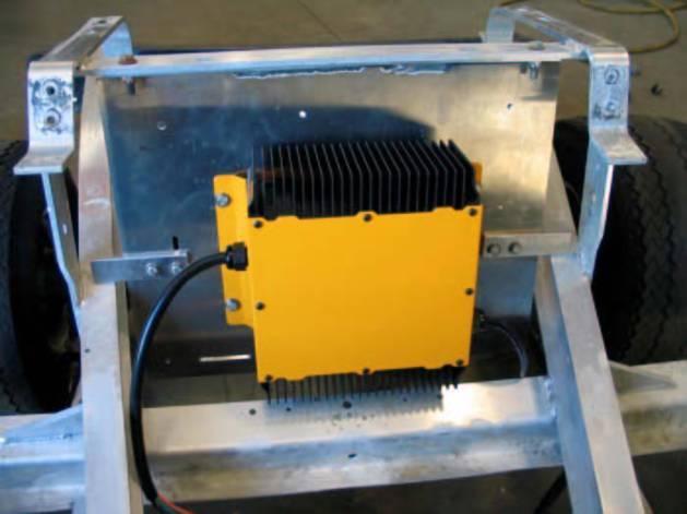
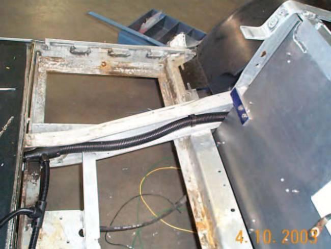
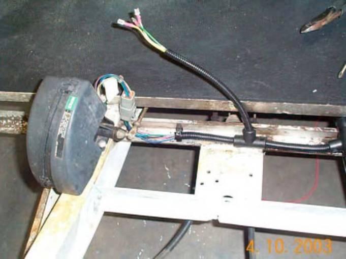
2 Installation Instructions Club Car Curtis Controller 1. Disconnect Negative Battery Cable, Disconnect Positive Battery Cable. 2. Remove cart s rear body. (Removal of front body is optional). 3. Disconnect all Motor and Controller wires. 4. Remove original Motor and Controller (remove controller mounting plate, if equipped). 5. Remove original wiring harness. Unplug any connector (cut as little as possible). If equipped with Rear Brake Lights Kit (DIAGRAM 2.1), label and keep factory wires from the brake pedal/ park switch. Theses wires will be reused to enable the brake lights. (See DIAGRAM 2.2 & 2.3) 6. Install new AC 9 Motor. (Use supplied ¼-20 Bolts, reuse original 5/16-18 Bolt Do not over torque Motor Bolts). 7. If clearance from the passenger shock mount to the motor s fan shield is less than one inch (viewing from the top), cut/trim passenger side rear shock ( See PICTURE 1.1 for reference). This procedure is not needed if cart has been lifted. 8. With the supplied controller mounting plate, reposition the controller plate supports to the opposite side. The supports were originally installed such way for shipping purposes. Adjust the supports as needed after reposition. 9. Install the Controller & Factory Main Contactor to mounting plate. (Use supplied ¼-20 bolts and lock-washers). Main plug on controller should be positioned to the bottom right of plate. 10. Install the Controller mounting plate in cart. Top bracket mounts to the bottom of the body support. See PICTURE 1.2 Page 2 of 16
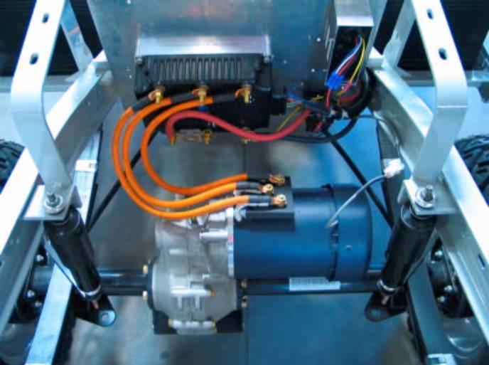
3 11. Install the battery charging equipment. The charging equipment would be either the factory Charge Computer or an on-board Delta-Q Battery Charger For Factory Charge Computer, see PICTURE 1.2 and DIAGRAM 2.4 for reference For on-board Delta-Q Battery Charge, see PICTURE 1.3 and DIAGRAM 2.5 for reference. 12. Connect Motor Cables from the controller to the AC9 Motor at each appropriate phase. Motor Cables and Battery Cables should be at least #2 AWG. See DIAGRAM 2.10 for reference. 13. Connect one side of the Main Contactor to the Fuse Post on the Controller. 14. Connect Negative Battery Cable to the controller. (DO NOT connect to Battery at this point). 15. Install Wiring Harness. See PICTURES 2.1 & 2.2 and DIAGRAMS Connect the throttle connectors (R2 & R3) from the wiring harness to the throttle module. See Diagram Connect wires to FWD/REV switch, See DIAGRAM Drill a 2 1/16 hole in the dash panel for the Dash Display. See DIAGRAM 2.8 for Dash Panel Connections 19. Plug cable with 8 pin connector into the back of the Dash Display. 20. Connect Red Wire to one side of Key switch. See DIAGRAM If charge computer is used, connect orange wire from charge light to the same side of the key switch as red wire. Page 3 of 16
4 21. Connect Blue wires to key switch (See DIAGRAM 2.8). Extra Blue jumpers/splices are required to connect the Golf/Street Switch, and optional Brake light Relay. 22. Connect the Yellow wire to the + (positive) side of the reverse buzzer, and the Gray wire to the (negative) side. See DIAGRAM Connect a Blue wire from the key switch to terminal 2 on the Golf/Street switch, and the Brown wire to terminal 1. (Golf Mode is selected when terminals 1 and 2 are connected together). See DIAGRAM For carts equipped with Rear Brake Light Kit, install a 12VDC automotive type relay in a suitable location where both factory and system wires can be connected together. The factory brake wires were disconnected and labeled at step #5. The below connections can be reviewed by using the DIAGRAMS 2. 2, 2. 3 & Connect the factory +12V source wire to the relay at terminal # Connect the factory RED wire of the rear brake lights to the Brake Relay at terminal # Connect a Blue wire from the key switch to the Brake Relay at terminal Connect the Orange wire to the Brake Relay at 85 terminal. 25. Connect Orange/White wire to the (negative side of the Main Contactor), and Blue/White wires to the + (positive side). Remove any resistor, diode. 26. Connect Fuse Wire and the + Battery cable to the Main Contactor. If equipped with Charge Computer, Connect Red Wire from Charge Computer to the same Terminal. (Yellow wire on Charge Computer not used. See DIAGRAM 2.4). 27. Plug in Encoder Cable. Page 4 of 16
5 28. DOUBLE CHECK ALL CONNECTIONS. 29. Secure all wires, harnesses and cables to the cart s frame by using tie straps. 30. Install 10 Amp Fuse at the fuse holder in the system harness. 31. Connect (negative) Battery Cable. 32. Test Cart on jack stands. Page 5 of 16
6 Driving the car with the A-C Drive System When key switch is first turned on, the system needs about 2 seconds to come online. After this time has expired, select the desired drive direction at the Forward/Reverse switch and press the accelerator pedal. The drive wheels could be in either direction when first turned on. BDI: (Dash Display), the BDI will display Battery Charge level (LED s at bottom) as well as text messages. BDI Message MPH GOLFMODE REVERSE LOWBATT Mode Cart in Street Mode (displays vehicle speed) Cart in Golf Mode (see note below) Cart in Reverse direction (see note below) Cart in Limp Home mode (see note below) Street Mode gives the vehicle a Max speed of 25 Miles per hour. Acceleration & Regenerative Brake torque are set at maximum level. When in Golf Mode the cart speed is limited to 12 Miles per hour. Acceleration & Regenerative Brake torque are also reduced. Drive Mode can be changed on The Fly. There is no need to stop the vehicle when changing from Street to Golf or vice-versa. When Cart is in Reverse, speed is reduced to 8 Miles per hour. Acceleration & Regenerative Braking torque are also reduced. Limp Home mode is automatically activated when the Battery charge level has dropped below 20%. The maximum cart speed is restricted up to 15 Miles per hour at Street mode. It is recommended to charge the batteries as soon as possible to prevent damage to the batteries from being over discharged. Page 6 of 16
7 CLUB CAR FACTORY BRAKE LIGHT KIT WIRING DETAIL -DIAGRAM 2.1 Page 7 of 16
8 HPEV AC-9 SYSTEM BRAKE LIGHT WIRING DETAIL -DIAGRAM 2.2 (COMMON) RED/ YELLOW (Normally Closed) PARK SWITCH PARK SWITCH WIRING DETAIL NORMALLY CLOSED NORMALLY CLOSED NORMALLY OPEN NORMALLY OPEN COMMON RED / YELLOW COMMON PURPLE BRAKE SWITCH WIRING DETAIL PURPLE (Normally Closed) BRAKE SWITCH (COMMON) HPEV SYSTEM WIRING HARNESS FROM +12V BATTERY DISCONNECT FACTORY BRAKE LIGHT WIRES AND RECONNECT TO A 12V AUTOMOTIVE RELAY (SEE DIAGRAM 2.3) RED TO FACTORY BRAKE LIGHT Page 8 of 16
9 BRAKE LIGHT REWIRING RELAY DETAIL -DIAGRAM 2.3 TO FACTORY BRAKE LIGHTS RED ORANGE FROM HPEVS SYSTEM HARNESS FROM HPEVS SYSTEM HARNESS BRAKE LIGHT RELAY FROM +12V BATTERY Page 9 of 16
10 CLUB CAR WIRING HARNESS with CHARGE COMPUTER (ORIGINAL EQUIPMENT) - DIAGRAM 2.4 FORWARD/ REVERSE SWITCH SEE DIAGRAM 2.7 WHITE RED-YELLOW YELLOW RED-YELLOW PARK SWITCH 6 PIN PLUG TO MOTOR ENCODER PURPLE BRAKE SWITCH 35 PIN CONNECTOR WIRE BUNDLE GREEN BLACK/ WHITE PURPLE/ WHITE YELLOW/ WHITE THROTTLE CONNECTIONS YELLOW GRAY DASH PANEL BROWN SEE DIAGRAM 2.8 ORANGE RED FUSE 10A / WHITE + Main Contactor YELLOW (NOT USED) RED TO BATTERY POS (+) #2 CABLE 10 GAUGE BLACK GRAY BROWN CHARGER PLUG WHITE/ RED 8 PIN DISPLAY PLUG BROWN FORM ORIGINAL CHARGE COMPUTER IF USED ORANGE/ WHITE - 10 GAUGE BLACK HOLE IN CHARGE COMPUTER TO BATTERY POS. (+) TO CONTROLLER POS (+) MAIN FUSE #2 CABLE EXTEND WIRE AND CONNECT TO BATTERY NEG. (-) Page 10 of 16
11 CLUB CAR WIRING HARNESS with ON BOARD DELTA-Q BATTERY CHARGER - DIAGRAM 2.5 FORWARD/ REVERSE SWITCH SEE DIAGRAM 2.7 WHITE RED-YELLOW YELLOW RED-YELLOW PARK SWITCH 35 PIN CONNECTOR 6 PIN PLUG TO MOTOR ENCODER WIRE BUNDLE PURPLE GREEN BLACK/ WHITE PURPLE/ WHITE YELLOW/ WHITE BRAKE SWITCH THROTTLE CONNECTIONS YELLOW GRAY BROWN ORANGE RED DASH PANNEL SEE DIAGRAM 2.8 FUSE 10A WHITE/ RED GREEN 8 PIN DISPLAY PLUG / WHITE + TO BATTERY POS (+) #2 CABLE ORANGE/ WHITE - Main Contactor RED BLACK WHITE BLACK - HOT WHITE - NEUTRAL GREEN - GROUND 110 VOLT AC PLUG TO CONTROLLER POS (+) MAIN FUSE #2 CABLE TO BATTERY NEG. (-) TO BATTERY POS. (+) Page 11 of 16
12 FORWARD/ REVERSE SWITCH DETAIL - DIAGRAM 2.6 WHITE RED/ YELLOW YELLOW Page 12 of 16
13 CLUB CAR DASH PANEL WIRING DETAIL - DIAGRAM 2.8 YELLOW GRAY REVERSE BUZZER 1 BROWN 2 ORANGE RED KEY SWITCH GOLF / STREET SWITCH ORANGE BROWN (FROM CHARGE CONTROLLER IF USED) CHARGE LIGHT TO BRAKE LIGHTS WHITE / RED BDI CABLE MENU DASH DISPLAY +12V IN BRAKE LIGHT RELAY Page 13 of 16
14 NOTICE: This drawing is the property of Hi Performance Electric Vehicle Systems Inc., and/or its subsidiaries and affiliates (individually and collectively HPEVS ), and contains highly proprietary, confidential, and trade secret information of HPEVS. The recipient of this drawing agrees (a) to use the information contained herein for the purpose for which it was furnished by HPEVS (b) to return this drawing upon HPEVS request. This notice shall appear on any complete or partial reproduction of this drawing. KEY SWITCH REVISIONS REV ORIGINATOR DESCRIPTION APPROVED A INITIAL RELEASE R1 AMP KSI BRAKE RELAY BACK UP BUZZER MAIN CONTACTOR COIL I/O GROUND MOTOR TEMP SENSOR PEDAL INTERLOCK MENU BUTTON BRAKE SWITCH GOLF / STREET SWITCH COIL RETURN POT HIGH POT WIPER POT LOW FOWARD 12V POWER CNTRL 5V POWER CNTRL TX SERIAL RX SERIAL ENCODER PHASE A ENCODER PHASE B REVERSE NOTES: TO BRAKE LIGHTS 18 AWG ORANGE 18 AWG GRAY 18 AWG PURPLE 18 AWG BRAKE LIGHTS RELAY ORANGE/ WHITE18 AWG BLACK/ 18 AWG YELLOW/ BLACK 18 AWG GREEN 18 AWG WHITE/ RED 18 AWG BROWN 18 AWG / WHITE 18 AWG BLACK/ WHITE 18 AWG YELLOW/ WHITE 18 AWG PURPLE/ WHITE 18 AWG WHITE 18 AWG RED/ 18 AWG RED/WHITE 18 AWG GREY/ 18AWG GREEN/ WHITE 18 AWG TAN/BLACK 18 AWG TAN 18 AWG YELLOW 18 AWG (*1) BLACK AND WHITE NOT USED ON 2 WIRE POT. SELECT TYPE 3 PARAMETER. (*2) NORMALLY CLOSED SWITCH. OPEN FOR PARK. IF SWITCH NOT USED, RED/YELLOW WIRE IS CONNECTED TO. (*3) MENU BUTTON IS OPTIONAL USE WITH DISPLAY. NORMALLY OPEN; MOMENTARY (*4) REMOVE ANY DIODES OR RESISTOR FROM MAIN CONTACTOR. (*5) USE 400A FUSE IN 650 SYSTEM. USE 300A FUSE IN 350 SYSTEM. (*6) NORMALLY CLOSED. CONTACTS MUST BE CLOSED WHEN BRAKE PEDAL IS PRESSED; OPEN WHEN BRAKE PEDAL IS NOT PRESSED. (*7) MOTOR TEMP SENSOR NOT USED FOR GOLF CART APPLICATION. (*8) SPLICE S4 TO BE PERFORMED BY THE END USER. 12V IN S1 S2 FOWARD REVERSE FORWARD / REVERSE SWITCH BACK UP BUZZER POT HIGH POT WIPER POT LOW RED/ WHITE 18 AWG BLACK/ 18 AWG TAN 18 AWG TAN/ BLACK 18 AWG BLACK/ 18 AWG YELLOW/ BLACK 18 AWG I/O GROUND TX SERIAL 12V POWER CNTRL RX SERIAL P4 DEUTSCH DTM-04-6P R4 DEUTSCH DTM-06-6S RED/ YELLOW 18AWG B A C R2 DEUTSCH DT-06-3S KSI MOTOR ENCODER CABLE RED/ WHITE 22 AWG BLACK/ 22 AWG TAN 22AWG TAN/ BLACK 22 AWG BLACK 22 AWG PURPLE 22 AWG 18AWG 1 PARK SWITCH (NOTE *2) 2 THROTTLE MODULE 18AWG BLACK/ 18 AWG GREY/ 18AWG RED/ 18 AWG R3 DEUTSCH DT-06-2S GREEN/ WHITE 18 AWG R6 MOLEX MINI FIT JR Note: Pins 2, 3, 4, & 7 are not connected AWG BRAKE SWITCH (NOTE *6) DISPLAY R5 MOLEX SL SERIES MOTOR ENCODER MOTOR TEMP SENSOR (NOTE *7) S3 W V U MOTOR 18AWG MENU BUTTON (NOTE *3) GOLF / STREET SWITCH 18AWG 18AWG 18AWG HPEV SYSTEM WIRING DETAIL - DIAGRAM 2.9 CAD TYPE CAD LOC. CAD FILE VISIO OPER. NO. UNIT DRAWING DESIGN S4 (NOTE *8) 35 PIN CONNECTOR (SEE R1) CHECKED 10A +A1 -A2 DETAIL SAFETY RED 18AWG +48V OR 72V W MAIN CONTACTOR (NOTE *4) B - B + V TITTLE U SCALE DATE REVISION E NONE 12/29/10 SHEET 1 OF 1 B E A (NOTE *5) Added R2 & R3 connectors Updated revision sequeence to match revision sequence recorded from supplier. Previous part number recorded by the supplier will be obsolete. New part number is listed in the drawing title block. M issing dimensions were addded 11/15/ CLUBCAR-001 CLUB CAR SYSTEM SCHEMATICS Page 14 of 16 DRW SIZE B HPEVS
15 HIGH CURRENT WIRING DETAIL - DIAGRAM 2.10 CONTROLLER U V W 35 PIN CONNECTOR Main Contactor + - / WHITE FUSE B + B - ORANGE/ WHITE FRONT OF CART 6 PIN TO WIRING HARNESS U V W MOTOR Page 15 of 16


16 PICTURE 1.1 PICTURE 1.2 PICTURE 1.3 PICTURE 2.1 PICTURE 2.2 CONTROLLER MOUNTING Page 16 of 16
INSTALLATION INSTRUCTIONS
 1551 S. Vineyard Avenue Ontario, CA 91761 (909) 923-1973 INSTALLATION INSTRUCTIONS E-Z-GO Installation Notes CURTIS 1234, 1236 OR 1238 AC INDUCTION MOTOR/ CONTROLLER EZ-GO Curtis Controller Installation
INSTALLATION INSTRUCTIONS SINGLE CHANNEL ISOLATOR
 1551 S. Vineyard Avenue Ontario, CA 91761 (909) 923-1973 INSTALLATION INSTRUCTIONS SINGLE CHANNEL ISOLATOR REVISION: C 11/08/2012 INSTRUCTIONS The following instructions are meant to supplement the installation
Electrical Schematics and Documentation
 1551 S. Vineyard Avenue Ontario, CA 91761 (909) 923-1973 Electrical Schematics and Documentation FOR CURTIS 1232-1238 E AND SE VERSION CONTROLLERS SOFTWARE VERSIONS 5.32 AND HIGHER FOR SINGLE AND DUAL
INSTALLATION INSTRUCTION
 1551 S. Vineyard Avenue Ontario, CA 91761 (909) 923-1973 INSTALLATION INSTRUCTION Club Car Precedent Installation Notes CURTIS 1234, 1236 OR 1238 AC INDUCTION MOTOR/ CONTROLLER REVISION: B This kit is
INSTALLATION INSTRUCTIONS. Yamaha G19 Installation Notes
 620 Magnolia Avenue Suite B Ontario, CA 91762 (909) 923-1973 INSTALLATION INSTRUCTIONS Yamaha G19 Installation Notes CURTIS 1232, 1234, 1236 OR 1238 AC INDUCTION MOTOR/ CONTROLLER Yamaha G 19 Installation
Instructions for Throttle & Battery Filling Pump Set Up
 620 Magnolia Avenue Suite B Ontario, CA 91762 (909) 923-1973 Instructions for Throttle & Battery Filling Pump Set Up Version: 800 After March 2007 with Version 8.00U Software Instructions for Throttle
ITCEMS950 Idle Timer Controller - Engine Monitor Shutdown Isuzu NPR 6.0L Gasoline Engine
 Introduction An ISO 9001:2008 Registered Company ITCEMS950 Idle Timer Controller - Engine Monitor Shutdown 2014-2016 Isuzu NPR 6.0L Gasoline Engine Contact InterMotive for additional vehicle applications
Idle Timer Controller - ITC515-A Ford Transit Contact InterMotive for additional vehicle applications
 An ISO 9001:2008 Registered Company Idle Timer Controller - ITC515-A 2015-2018 Ford Transit Contact InterMotive for additional vehicle applications Overview The ITC515-A system will shut off gas or diesel
D&D Motor Systems, Inc.
 D&D Motor Systems, Inc. Programmable Regen Controller Manual & Schematics BE ADVISED, D&D Motor Systems, Inc. does not design and manufacture controllers. We provide them as an extension to our existing
Idle Timer Controller - ITC Freightliner MT45 Contact InterMotive for additional vehicle applications
 An ISO 9001:2008 Registered Company System Operation Idle Timer Controller - ITC805 2013-2018 Freightliner MT45 Contact InterMotive for additional vehicle applications The ITC805 system shuts down idling
Club Car IQ Technical Information Updated
 Club Car IQ Technical Information Updated 6-2-17 Begin GENERAL WIRING DIAGRAM Next TECHNICAL ASSISTANCE Solenoid Does Not Close Solenoid Closes But No Travel Vehicle Travels in reverse when in forward
Idle Timer Controller - A-ITC520-A Ford E Series Ford F250 - F Ford F250 - F550 (*B-ITC520-A) F650/F750
 F650/F750") An ISO 9001:2008 Registered Company Idle Timer Controller - A-ITC520-A 2009-2018 Ford E Series 2008-2016 Ford F250 - F550 2017-2018 Ford F250 - F550 (*B-ITC520-A) 2016-2018 F650/F750 *Uses the Ford 24-Pin
An ISO 9001:2008 Registered Company Idle Timer Controller - A-ITC520-A 2009-2018 Ford E Series 2008-2016 Ford F250 - F550 2017-2018 Ford F250 - F550 (*B-ITC520-A) 2016-2018 F650/F750 *Uses the Ford 24-Pin
Club Car 1515 to Curtis 1268 Conversion
 Club Car 1515 to Curtis 1268 Conversion Installation Instructions 62-12685501CKXI Rev. 03 4/17/14 Page 1 of 7 1515 to Curtis 1268 Conversion Installation Instructions Before you start turn Tow/Run switch
Idle Timer Controller - A-ITC620-A Chevrolet Express/GMC Savana
 An ISO 9001:2008 Registered Company Idle Timer Controller - A-ITC620-A1 2009-2018 Chevrolet Express/GMC Savana Contact InterMotive for additional vehicle applications Introduction The A-ITC620-A1 is an
INSTALLATION INSTRUCTION
 620 Magnolia Ave. Suite B Ontario, CA 91762 (909) 923-1973 INSTALLATION INSTRUCTION Club Car Precedent Lithium Battery Pack Installation Notes Including Cars with Installed HPEVS Drive Systems REVISION:
620 Magnolia Avenue Suite B Ontario, CA (909) Diagnostic and Troubleshooting. Golf Cart. Revision: A Date:
 Diagnostic and Troubleshooting. Golf Cart. Revision: A Date:") 620 Magnolia Avenue Suite B Ontario, CA 91762 (909) 923-1973 Diagnostic and Troubleshooting Golf Cart Revision: A Date: 9-25-13 Diagnostics Diagnostics information can be obtained by observing the fault
620 Magnolia Avenue Suite B Ontario, CA 91762 (909) 923-1973 Diagnostic and Troubleshooting Golf Cart Revision: A Date: 9-25-13 Diagnostics Diagnostics information can be obtained by observing the fault
SYMPTOM POSSIBLE CAUSES CORRECTIVE ACTION. Batteries Battery connections
 ELECTRICAL SYSTEM AND TESTING TROUBLESHOOTING GUIDE 2 Troubleshooting 11 TROUBLESHOOTING GUIDE 2 SYMPTOM POSSIBLE CAUSES CORRECTIVE ACTION Vehicle does not operate Batteries Batteries discharged Charge
INSTALLATION INSTRUCTION. Club Car Precedent Lithium Battery Pack Installation Notes
 1551 S. Vineyard Avenue Ontario, CA 91761 (909) 923-1973 INSTALLATION INSTRUCTION Club Car Precedent Lithium Battery Pack Installation Notes REVISION: A Date: 11-12-16 Disclaimer: HPEVS assumes that the
Idle Timer Controller - A-ITC620-A Chevrolet Express/GMC Savana
 Introduction An ISO 9001:2015 Registered Company Idle Timer Controller - A-ITC620-A1 2009-2019 Chevrolet Express/GMC Savana Contact InterMotive for additional vehicle applications The A-ITC620-A1 is an
OBC (On-Board Computer) By-pass Kit Installation Instructions Lester Electrical By-pass Kit #38836 for use with Club Car Precedent and DS vehicles
 By-pass Kit Installation Instructions Lester Electrical By-pass Kit #38836 for use with Club Car Precedent and DS vehicles") OBC (On-Board Computer) By-pass Kit Installation Instructions Lester Electrical By-pass Kit #38836 for use with Club Car Precedent and DS vehicles The Lester Electrical OBC (On-Board Computer) Bypass Kit
OBC (On-Board Computer) By-pass Kit Installation Instructions Lester Electrical By-pass Kit #38836 for use with Club Car Precedent and DS vehicles The Lester Electrical OBC (On-Board Computer) Bypass Kit
LHT CC LIGHT WIRING Instructions for Club Car DS Models
 LHT CC5 1001 LIGHT WIRING Instructions for Club Car DS Models This Light Kit includes: (1) Main Wire Harness with Dual InLine Fuses (1) Headlight Switch (1) Left hand headlight (1) Right hand headlight
Wiper motor bolt and spacer. 3. Place relays as shown in picture so you can route the wires.
 TSB Fan Relay Kit Please refer to a factory repair manual when working on your car. 1. Disconnect battery cables from the battery. 2. Remove bolt and spacer from wiper motor as shown in the picture. Wiper
FROG-D 3P. FREQUENCY READOUT OF GENERATOR THREE PHASE GENERATOR DISPLAY MODELS: FDA700 for Delta Winding FDA710 for Star Winding
 Document Number: XE-FDA7PM-R0A FDA700 Rev160509 FROG-D 3P FREQUENCY READOUT OF GENERATOR THREE PHASE GENERATOR DISPLAY MODELS: FDA700 for Delta Winding FDA710 for Star Winding FIRE RESEARCH CORPORATION
DirectMount EXHAUST BRAKES
 DirectMount EXHAUST BRAKES APPLICATION: Fixed Orifice and PRXB Exhaust Brakes 2003 2005 Dodge Trucks with 3.5" & 4" Exhaust and 47RE & 48RE Automatic Transmissions Only Vehicles with an existing air compressor
-----
 ----- - - -- - - -- - -- - - NOTE: #32 WIRE DOES NOT APPLY TO 8 AND 14 CIRCUIT HARNESSES ELECTRIC FAN #1 TO FAN SWITCH (GRAY) #21 TEMP. GAUGE (GREEN) #2 TO AC SWITCH (BLACK) JUMPER WIRE ALTERNATORS
Control Replacement # Page 1 REPLACEMENT OF OBSOLETE SEMI- AUTO CONTROLS WITH KIT #
 Control Replacement #500643 Page 1 R epla c ement of s emi-a uto c ontr ols with r epla c ement kit # 500643 Content CONTENTS Control Replacement 2 Calibration 5 Operating Instructions 6 Preventive Maintenance
PRXB EXHAUST BRAKE HIGH PERFORMANCE
 HIGH PERFORMANCE PRXB EXHAUST BRAKE C44059, C4406, C44063, C44065 APPLICATION 994-2002 DODGE RAM AUTOMATIC TRUCKS EQUIPPED WITH 47RE TRANSMISSIONS WITH 5.9L, 24 VALVE CUMMINS DIESEL ENGINES GETTING STARTED
99 Ford Ranger EV EPT2 Conversion Wiring Instructions
 99 Ford Ranger EV EPT2 Conversion Wiring Instructions There are two electrical systems. One 144 volt high current traction circuit and one low voltage control and accessory circuit. The low voltage circuit
Xebra Electrical Component Locations
 Xebra Electrical Component Locations Last updated on April 12, 2007 Copyright 2007. This document my not be reprinted, published, emailed or posted on the Internet without the approval of ZAP. Component
OBC (On-Board Computer) By-pass Kit Installation Instructions Lester Electrical By-pass Kit #38836 for use with Club Car
 By-pass Kit Installation Instructions Lester Electrical By-pass Kit #38836 for use with Club Car") OBC (On-Board Computer) By-pass Kit Installation Instructions Lester Electrical By-pass Kit #38836 for use with Club Car Precedent and DS vehicles (Only compatible with OBC/Car that has a 6 Pin Deutsch
OBC (On-Board Computer) By-pass Kit Installation Instructions Lester Electrical By-pass Kit #38836 for use with Club Car Precedent and DS vehicles (Only compatible with OBC/Car that has a 6 Pin Deutsch
WARRANTY WILL BE VOID If These Steps are Not Performed Before Installing The Control STEPS TO PERFORM BEFORE CONTROL INSTALLATION
 Curtis 1268-5411 This sheet is provided to aid in the installation of your remanufactured CURTIS controller. Upon installation, you may encounter problems that may, or may not, be due to a faulty controller.
jegs.com
 Contents Wiring Harness w/ Fuse Panel Installation Instructions Turn Signal Plug w/ Terminals 2 Headlight Plugs 3/4 Grommet 10 ¼ Terminals 4 Ring Terminals 10 Wire Ties Fusible Link 2 Screws & Nuts 2 Plastic
Permanent Magnet Motor Speed Controller 1212S / 1212P / 1212C
 Motor Controllers Permanent Magnet Motor Speed Controller 1212S / 1212P / 1212C www.curtisinstruments.com 1 The Curtis Model 1212S, 1212P and 1212C Motor Speed Controllers provide efficient, optimal control
CLUBCAR PD-PLUS INSTALLATION GUIDE
 Installation Guide: ClubCar PD-Plus w/dcx Controller Tony Thorne Dir OEM Services ALLTRAX Inc. December 18th, 2006 (Update Sept, 04, 2007) CLUBCAR PD-PLUS INSTALLATION GUIDE The following steps describe
INSTRUCTIONS. 20 Circuit Wiring Kit Instructions October 2009, Speedway Motors, Inc.
 1 MAIN FUSE PANEL The main fuse panel harness s designed to be mounted under the dash a the firewall in an area close to the steering column. The enclosed representation of the main dash harness shows
Maintenance and Service Manual Supplement PowerDrive Plus Vehicles
 1998-1999 Maintenance and Service Manual Supplement PowerDrive Plus Vehicles Manual Number 101968405 Edition Code 0299C1208B FOREWORD The Club Car PowerDrive Plus electric vehicle is engineered and built
Property of American Airlines
 MODEL CBL2000E-II MOBILE BELT CONVEYOR CHARLATTE AMERICA, INC. 600 MOUNTAIN LANE P.O. BOX 968 BLUEFIELD, VA 24605 TELEPHONE (276) 326-1510 FAX (276) 326-1602 SPARE PARTS FAX: (276) 326-3898 ONLINE: www.charlatteamerica.com
Installing the Throttle Commander
 Installing the Throttle Commander Ford 6.0L Diesel Powerstroke 2005-2007 F250-550 Super Duty 2005-2010 E250-550 Econoline (8500+ GVW) Ford 6.4L Diesel Powerstroke 2008-2010 F250-550 Super Duty T500107
ECO3-601/602 EcoStar III * Chevy Express/GMC Savana Contact Intermotive for additional vehicle applications
 An ISO 9001:2015 Registered Company ECO3-601/602 EcoStar III 2009-2019* Chevy Express/GMC Savana Contact Intermotive for additional vehicle applications * In 2017-2018, the ignition switches on Chevy Express
Aftermarket Interface Module
 An ISO 9001:2008 Registered Company Aftermarket Interface Module (2015-2018 Ford Transit) AIM514-B High Side Solenoid type Coolant Valve Control AIM515-B Motor Reversing type Coolant Valve Control Introduction
TSX3.0. w w w. n a v i t a s v e h i c l e s y s t e m s. c o m
 TSX3.0 DESCRIPTION The TSX line of fully-programmable controllers for separately excited motors have half-h armature control and independent full- H field control enabling contactor-less reversing and
INSTRUCTIONS FOR REMOVAL OF GROUND FAULT PROTECTION DEVICE FROM HOBART GENERATOR SETS SPECIFICATION NUMBERS
 081385 INSTRUCTIONS FOR REMOVAL OF GROUND FAULT PROTECTION DEVICE FROM HOBART GENERATOR SETS SPECIFICATION NUMBERS 6184-2 HOBART BROTHERS COMPANY Power Systems Division Troy, Ohio 45373 INSTRUCTIONS FOR
AIRSTREAM - BATTERY CONTROL CENTER - Diesel
 P/N 00-00755-000 CAUTION: The Battery Control Center is a centralized power switching, fusing, and distribution center. Power from both the chassis and coach batteries is fed into the box. The full power
WIRE SYSTEM PRO15 ULTRA SMALL 15 FUSE 24 CIRCUIT 118 TERMINAL PANEL WIRE SYSTEM
 TECH UPPORT: 503.693.1918 WIRE YTEM WWW.KEEPITCLEANWIRING.COM PRO15 ULTRA MALL 15 FUE 24 CIRCUIT 118 TERMINAL PANEL WIRE YTEM IMPORTANT: The below instructions are referring to a general installation.
Club Car 1510 to Curtis 1268 Conversion
 Club Car 1510 to Curtis 1268 Conversion Installation Instructions 62-12685501CKI Rev. 05 7/18/14 Page 1 of 7 1510 to Curtis 1268 Conversion Installation Instructions Before you start turn Tow/Run switch
UNIVERSAL WIRING HARNESS Installation Manual
 UNIVERSAL WIRING HARNESS Installation Manual Terminals are provided for most connections on your wiring kit. Following the gauge manufacturer s instructions, use the terminals supplied with your gauge
INSTRUCTIONS FOR REMOVAL OF GROUND FAULT PROTECTION DEVICE FROM HOBART GENERATOR SETS SPECIFICATION NUMBER
 TO-161 073085 INSTRUCTIONS FOR REMOVAL OF GROUND FAULT PROTECTION DEVICE FROM HOBART GENERATOR SETS SPECIFICATION NUMBER 6184-3..-.-.._. HOBART BROTHERS COMPANY Power Systems Division Troy, Ohio 45373
C FORD F250 / F L POWERSTROKE DIESEL WITH AUTOMATIC TRANSMISSIONS ONLY
 EXHAUST BRAKES C40019 1999-2003 FORD F250 / F350 7.3L POWERSTROKE DIESEL WITH AUTOMATIC TRANSMISSIONS ONLY Getting Started Thank you and congratulations on your purchase of a Pacbrake exhaust retarder.
MANUAL. MultiMode MOTOR CONTROLLER CURTIS INSTRUMENTS, INC.
 1210 MANUAL MODEL 1210 MultiMode MOTOR CONTROLLER 2004 CURTIS INSTRUMENTS, INC. DESIGN OF CURTIS PMC 1200 SERIES CONTROLLERS PROTECTED BY U.S. PATENT NO. 4626750. 1210 Manual, p/n 37278 Rev. A: January
MANUAL. MultiMode MOTOR CONTROLLER CURTIS INSTRUMENTS, INC.
 MANUAL MODEL 1228 MultiMode MOTOR CONTROLLER 2003 CURTIS INSTRUMENTS, INC. DESIGN OF CURTIS PMC 1200 SERIES CONTROLLERS PROTECTED BY U.S. PATENT NO. 4626750. CURTIS INSTRUMENTS, INC. 200 Kisco Avenue Mount
An ISO 9001:2008 Registered Company
 An ISO 9001:2008 Registered Company Introduction Engine Monitor System 2009-2018 Ford E Series (EMS501-D) 2008-2010 Ford F250-550 6.2L, 6.8L (EMS506-D) 2011-2016 Ford F250-550 6.2L, 6.8L (EMS507-D) 2017
Installing the FX302 into the E-Z-GO DCS Golf Car
 Installing the FX302 into the E-Z-GO DCS Golf Car 1015 Harrisburg Pike Carlisle, PA 17013 Phone: (717) 254-3747, Fax: (717) 254-3777 Website: www.fsip.biz Note: To prevent draining the batteries prematurely,
Boxer 322D Parts Manual
 BIG POWER IN ALL PLACES Boxer D Parts Manual Serial No.s and Higher Part No. -80 Phone: Sales - 800-8-00, Parts and Service - 800--88 www.boxerequipment.com Manufactured by: Morbark, Inc. 80 S. Winn Rd.,
CTC 400 Cab Trailer Communication Power Line Carrier Technology Communications for Trucks and Trailers
 WHEEL MONITOR CTC 400 Cab Trailer Communication Power Line Carrier Technology Communications for Trucks and Trailers Installation Manual for the CTC-400 Cab and Trailer Modules Wheel Monitor Inc. 1-905-641-0024
2004 Scion xa. PARKING LIGHTS (+) GREEN At Harness On Top Of Fuse Box DOOR TRIGGER (-) RED/WHITE In 9-Pin On Top Of Fuse Box
 GREEN At Harness On Top Of Fuse Box DOOR TRIGGER (-) RED/WHITE In 9-Pin On Top Of Fuse Box") ALARM REMOTE START WIRING WIRE COLOR LOCATION 12V CONSTANT WIRE WHITE/BLUE and Ignition Harness WHITE/RED STARTER WIRE BLACK Ignition Harness 12V IGNITION WIRE BLACK/RED Ignition Harness SECOND IGNITION
ALARM REMOTE START WIRING WIRE COLOR LOCATION 12V CONSTANT WIRE WHITE/BLUE and Ignition Harness WHITE/RED STARTER WIRE BLACK Ignition Harness 12V IGNITION WIRE BLACK/RED Ignition Harness SECOND IGNITION
led light Kit included: tools needed: 2 LED Headlights 2 LED Tail Lights Wiring Harness Screws Straps Rocker Switch WILL FIT CLUB CAR DS
 led light Kit WILL FIT CLUB CAR DS 02-033 included: tools needed: 2 LED Headlights 2 LED Tail Lights Wiring Harness Screws Straps Rocker Switch Phillips head screw driver Cutting Tool Sandpaper Power Drill
HOLLEY VR2 FUEL PUMPS P/N & Installation Instructions 199R10975
 HOLLEY VR2 FUEL PUMPS P/N 12-3000 & 12-3000-2 Installation Instructions 199R10975 WARNING! THESE INSTRUCTIONS MUST BE READ AND FULLY UNDERSTOOD BEFORE BEGINNING INSTALLATION. FAILURE TO FOLLOW THESE INSTRUCTIONS
ELECTRICAL / GENERAL INFORMATION
 ELECTRICAL / GENERAL INFORMATION General Information Reading Electrical Schematics The schematic is made up of individual circuits laid out in a sequence of related functions. It is formatted with all
PRXB EXHAUST BRAKE MAXIMUM EXHAUST FLOW DESIGN
 MAXIMUM EXHAUST FLOW DESIGN PRXB EXHAUST BRAKE C44072/C44073/C44074/C44075/C44076 APPLICATION: 994-2002 DODGE RAM TRUCKS W/5.9L CUMMINS DIESEL ENGINES WITH MANUAL & AUTOMATIC TRANSMISSIONS STOCK DODGE
TL UNIVERSAL WIRING PROCEDURE
 UNIVERSAL WIRING PROCEDURE 3nov11jh TABLE OF CONTENTS 1 Control Kits 1.1. TIK10100 Universal Manual Hand Control 1.2. TIK10103 Universal Automatic Foot Control for Hydraulic Brakes 1.3. TIK10104 Universal
MSD Kawasaki Jet Ski 750 Enhancer CD Ignition PN 4251
 MSD Kawasaki Jet Ski 750 Enhancer CD Ignition PN 4251 Parts Included: 1 - MSD Enhancer CD Ignition 2-6mm Stainless Steel Flatwashers 2 - Zip Ties Supplies Required For Installation 1 Tube of Blue Loctite
Navitas Vehicle Systems Ltd. NAVITAS TAC A 48-72V CONTROLLER for AC INDUCTION MOTORS. Installation/Service Manual
 Navitas Vehicle Systems Ltd. NAVITAS TAC 1.0 600A 48-72V CONTROLLER for AC INDUCTION MOTORS Installation/Service Manual INSTALLATION INSTRUCTIONS FOR: E-Z-GO RXV 48V (CURTIS ) E-Z-GO RXV 23 48V (DANAHER
CTC 200 Cab Trailer Communication Power Line Carrier Technology Communications for Trucks and Trailers
 WHEEL MONITOR CTC 200 Cab Trailer Communication Power Line Carrier Technology Communications for Trucks and Trailers Installation Manual for the CTC-200 Modules 2004 Wheel Monitor Inc. 1-905-641-0024 Page
Light Kit will fit e-z-go rxv installation instructions included: tools needed: 2 Headlights 2 Tail Lights Wiring Harness Screws
 Revised Decemeber 2014 02-014 Light Kit will fit e-z-go rxv installation instructions included: tools needed: 2 Headlights 2 Tail Lights Wiring Harness Screws Straps Rocker Switch Phillips Head Screw Driver
Separately Excited Electronic Motor Speed Controller Model 1243 SepEx
 Motor Controllers Separately Excited Electronic Motor Speed Controller Model 1243 SepEx www.curtisinstruments.com 1 Curtis PMC Model 1243 SepEx programmable controllers provide smooth and seamless regenerative
Contacts The moveable contact, which is the one affected by the armature is sometimes referred to as the hinge contact.
 Relays & Wiring 101 Basically, a relay is an electrically operated, remotely controlled switch. A simple electromagnetic relay is an adaptation of an electromagnet. It consists of a coil of wire surrounding
Separately Excited Electronic Motor Speed Controller Model 1266 A/R SepEx
 Motor Controllers Separately Excited Electronic Motor Speed Controller Model 1266 A/R SepEx www.curtisinstruments.com 1 Curtis Model 1266 A/R SepEx controllers are programmable and microprocessor based,
GEN IV ROTARY CONTROL PANEL KIT
 GEN IV ROTARY CONTROL PANEL KIT 492050 GEN IV ROTARY CONTROL PANEL KIT No QTY PART No. DESCRIPTION. 2. 3. 4. 5. 6. 7. 8. 9. 0. 3 2 3 5 490006 24608-0 8235-VUB 497004 232002-VUA 230-VUP 23520 205550 20555
MANUAL 1207& 1207A CURTIS PMC. MultiMode MOTOR CONTROLLERS
 MANUAL 1207& 1207A MultiMode MOTOR CONTROLLERS 1999 CURTIS INSTRUMENTS, INC. DESIGN OF CURTIS PMC 1200 SERIES CONTROLLERS PROTECTED BY U.S. PATENT NO. 4626750. CURTIS PMC 235 East Airway Boulevard Livermore,
INSTALLATION INSTRUCTIONS 5.7L HEMI TRUCK HOT-ROD STYLE. Also covers LX 5.7L/6.1L Hemi with Truck or Manual Transmission **
 INSTALLATION INSTRUCTIONS 5.7L HEMI TRUCK HOT-ROD STYLE Also covers LX 5.7L/6.1L Hemi with Truck or Manual Transmission ** 5.7L Hemi Truck Hotrod Style Page: 2 5.7L Hemi Truck Hotrod Style Page: 3 Our
LP-2500/2600. Installation and Setup Guide. Lighting Control Panels. Revision 3.1 July 1999
 /2600 Lighting Control Panels Installation and Setup Guide Revision 3. July 999 Phone:770-429-3043 http://www.triateklighting.com sales@triateklighting.com Installation Guide /2600 Lighting Panels Table
MegaSquirt III for LS Style Engines. Hardware Install. 1. Disconnect and remove the battery from the vehicle.
 MegaSquirt III for LS Style Engines MegaSquirt controllers are experimental devices intended for educational purposes. MegaSquirt controllers are not for sale or use on pollution controlled vehicles. Check
an ISO 9001:2008 Registered Company 1963 IMPALA CONTROL PANEL CONVERSION KIT REV D 4/13/15, 1963 IMPALA CNTRL PNL INST PG 1 OF 16
 an ISO 9001:2008 Registered Company 1963 IMPALA CONTROL PANEL CONVERSION KIT 471063 901065 REV D 4/13/15, 1963 IMPALA CNTRL PNL INST PG 1 OF 16 Table of Contents PAGES 1. COVER 2. TABLE OF CONTENTS 3.
LSx Harness Installation. lsxeverything.com #BecauseYouShould
 LSx Harness Installation lsxeverything.com #BecauseYouShould Table of Contents Slide 1 Introduction Page Slide 2 Table of Contents Slide 3 Starting Instructions Slide 4 Power Connections Slide 5 Ground
Figure 1: A photograph of the Synercon Technologies Smart Sensor Simulator with the 70 pin Caterpillar connectors.
 SSS-ADEM3 The Smart Sensor Simulator (SSS) for the Caterpillar ADEM A3 and ADEM 2000 ECMs (collectively known as an ADEM III) enables investigators to download HVEDR data without risk of spoiling the data
Product Support Bulletin
 MODEL: SUBJECT: C2 BODY DEACTIVATION DOOR BUZZER, AIR DOOR W/ EXTERNAL KEY SWITCH DATE: DECEMBER 10, 2007 INDEX: C2 5 PAGE: 1 OF 6 DO NOT USE THIS PROCEDURE. INDEX C2 5, BULLETIN 5 IS NOW OBSOLETE AND
ION-01-6 PERFORMANCE SPEEDOMETER/TACHOMETER COMBO
 ION-01-6 PERFORMANCE SPEEDOMETER/TACHOMETER COMBO MOUNTING: It should be inserted into the opening from the front and the L-clamps will be installed from the back. Tighten the nuts on the L-clamps so that
ISIS Power Manual and Installation Guide Race Car Replicas- Superlite Coupe
 ISIS Power Manual and Installation Guide Race Car Replicas- Superlite Coupe Table of Contents Overview... 2 System Details... 3 Kit Includes... 3 Technical Specifications... 3 Harness Descriptions... 4
CMD-4000 SERIES REV. A 4+ FUNCTION REMOTE CONTROL DOOR LATCH OPENER SYSTEM INTRODUCTION
 CMD-4000 SERIES REV. A 4+ FUNCTION REMOTE CONTROL DOOR LATCH OPENER SYSTEM INTRODUCTION Thank you for purchasing the CMD-4000 series Remote Control Door Latch Opener System from Dakota Digital, Inc. This,
1969 CAMARO WITH AC CONTROL PANEL CONVERSION KIT an ISO 9001:2008 Registered Company
 an ISO 9001:2008 Registered Company 1969 CAMARO WITH AC CONTROL PANEL CONVERSION KIT 474269 904269 REV E 4/13/15, 69 CAMARO w/ AC CNTRL PNL INSTR PG 1 OF 17 Table of Contents PAGES 1. 2. 3. 4. 5. 6. 7.
40A A 40B. Horn Relay Connector. Brake Switch. Third Brake Light. Brake Switch. Brake Switch. Wires. page 3. Rear Body Feed Wires.
 Fuse Box Connections (viewed from underside) 4D 4C 4D 0 50 300 4C 43 7 39 3 6 4 93 A 2G 2F 2E 2D 2C 2B 2G 2F 2E 40 69A 2 1 5 27 69A 3A B 40A,B 11A,B 40A 156 Dimmer Dome Feed page 2 Horn Relay 2D 2 29 40B
LED Light Kit. installation instructions will fit *e-z-go rxv
 02-004 LED Light Kit will fit *e-z-go rxv installation instructions included: tools needed: 2 LED Headlights 2 LED Tail Lights Upgrade Wiring Harness Screws Straps Rocker Switch #2 Phillips bit Cutting
Ebling Back Blade Snow Plow Wireless Controller Kit Only sold by SnowplowsPlus.com and ControlAllWireless.com
 Ebling Back Blade Snow Plow Wireless Controller Kit Only sold by SnowplowsPlus.com and ControlAllWireless.com WARNING Always unplug the plow or shut off the battery breaker when in transport or not in
Tail lights. Headlights
 Revised December 2014 02-017 Light Kit will fit Yamaha G-Series* installation instructions included: tools needed: 2 Headlights 2 Tail Lights Wiring Harness Screws Straps Hazard Switch Phillips Head Screw
HL610-B Fast Idle, Lift Interlock Chevy 610 Van 6.0L and 6.6L Contact InterMotive for additional vehicle applications
 An ISO 9001:2015 Registered Company HL610-B Fast Idle, Lift Interlock 2009-2019 Chevy 610 Van 6.0L and 6.6L Contact InterMotive for additional vehicle applications Introduction The HighLock 610 is a wheelchair
Installing the Throttle Commander Ford F250 F550 Super Duty T L Diesel T L Diesel
 Installing the Commander Ford F250 F550 Super Duty T500106 2005-2007 6.0L Diesel T500116 2008-2010 6.4L Diesel 1.0 Preparing for Installation...5 2.0 Installing the Control...5 2.1 2005-2007 T500106 Connecting
Manual Models 1266 A /1266 R
 Manual Models 1266 A /1266 R Electronic Motor Controllers Curtis Instruments, Inc. 200 Kisco Avenue Mt. Kisco, NY 10549 www.curtisinstruments.com Read Instructions Carefully! Specifications are subject
MANUAL. Generation 2 CURTIS INSTRUMENTS, INC. MultiMode MOTOR CONTROLLER
 MANUAL MODEL 1243 Generation 2 MultiMode MOTOR CONTROLLER 2002 CURTIS INSTRUMENTS, INC. DESIGN OF CURTIS PMC 1200 SERIES CONTROLLERS PROTECTED BY U.S. PATENT NO. 4626750. CURTIS INSTRUMENTS, INC. 200 Kisco
Installation Manual. 12 Automotive Fuse Panel (AFP12) Version 2.2 March 2018
 Version 2.2 March 2018") Installation Manual 12 Automotive Fuse Panel (AFP12) Version 2.2 March 2018 Table of Contents Introduction... 2 What s Included... 3 Installation... 4 Features & Helpful Tips... 9 WAS492 Wire Harnesses...
Installation Manual 12 Automotive Fuse Panel (AFP12) Version 2.2 March 2018 Table of Contents Introduction... 2 What s Included... 3 Installation... 4 Features & Helpful Tips... 9 WAS492 Wire Harnesses...
72 Mustang Mach 1 tachometer cluster and gauge conversion
 72 Mustang Mach 1 tachometer cluster and gauge conversion Dated: 02-17-2009 (drafted by a Chevy person working on his first Ford -not good-) Revised: 11-05-2010 The following information pertains to how
3 Channel Remote Start / Keyless Entry System Installation Instructions
 Model AA-RS5CS Installation Manual 3 Channel Remote Start / Keyless Entry System Installation Instructions This Unit Is Intended For Installation In Vehicles With 12 Volt Negative Ground Electrical Systems,
Vehicle Alarm System With Channel 2 Auxiliary Output Installation Instructions
 Model PRO 9842 Installation Manual Vehicle Alarm System With Channel 2 Auxiliary Output Installation Instructions This Unit Is Intended For Installation In Vehicles With 12 Volt Negative Ground Electrical
Multiplexing system installation M
 MPX installation 53618-M Multiplexing system installation (the control module installed under power unit (pump cover) 53618-M (it requires light kit 800084 or 800086) Link to Install MPX controller harness
POWER TRIM 5 E DUAL POWER TRIM CONTROL
 POWER TRIM 5 E 22129 DUAL POWER TRIM CONTROL Table of Contents Page Important information..................... 5E-1 Testing Dual Power Trim System........... 5E-1 Relay Test............................
Covers All 430, 440, 441 and CJ Series Advanced Security Systems.
 INSTALL GUIDE Covers All 430, 440, 441 and CJ Series Advanced Security Systems www.ultrastarters.com Technical Support: 866-698-5872 ext 0 support@ultrastarters.com FCC/ID Notice This device complies with
Repair harness. Repair Harnesses
 Repair harness Repair Harnesses Truck side repair harness (2 plugs) 53632-B......2 Truck side repair harness (1 plug) 53470-02-B..4 MPX truck side repair controller harness 53625-MPX....5 MPX truck side
CUMMINS 6.7L EXHAUST BRAKE PRXB EXHAUST BRAKE KIT FOR 2007½-2015 TRUCKS EQUIPPED WITH 6.7L CUMMINS ISB DIESEL ENGINES. C Kit C Kit
 CUMMINS 6.7L EXHAUST BRAKE PRXB EXHAUST BRAKE KIT FOR 2007½-2015 TRUCKS EQUIPPED WITH 6.7L CUMMINS ISB DIESEL ENGINES C44038 4 Kit C44039 5 Kit BEFORE STARTING THE INSTALLATION please read the entire installation
TO ORDER PARTS CALL: (479) or
 or") Owner s Manual Industrial Ergonomic User-Friendly Hand Controls Date Manufactured: / / o Mart Cart XTi 24 Model 03522 - SKU# 280-3522 o Mart Cart XTi 24 Model 03524 - SKU# 280-3524 CONGRATULATIONS You
Owner s Manual Industrial Ergonomic User-Friendly Hand Controls Date Manufactured: / / o Mart Cart XTi 24 Model 03522 - SKU# 280-3522 o Mart Cart XTi 24 Model 03524 - SKU# 280-3524 CONGRATULATIONS You
INSTRUCTIONS Circuit Wiring Kit Instructions _2017. Fuse Box Connections. (viewed from underside) 2018, Speedway Motors, Inc.
 2018, Speedway Motors, Inc.") Fuse Box Connections (viewed from underside) 4D 4C 100 50 300 4D 4C 4B 4A 43 107 39 103 3B 2G 104 93 2F 2E 2D 2C 2B 40 69A 102 101 105 2G 2F 2E 3A A 2A B 40A,B 27 69A 106 201, Speedway Motors, Inc. 1 Fuse
Fuse Box Connections (viewed from underside) 4D 4C 100 50 300 4D 4C 4B 4A 43 107 39 103 3B 2G 104 93 2F 2E 2D 2C 2B 40 69A 102 101 105 2G 2F 2E 3A A 2A B 40A,B 27 69A 106 201, Speedway Motors, Inc. 1 Fuse
Installation Tips for your Crimestopper/ProStart Remote Start system (for GM vehicles) v1.01 updated 2/27/2012
 v1.01 updated 2/27/2012") Installation Tips for your Crimestopper/ProStart Remote Start system (for GM vehicles) v1.01 updated 2/27/2012 Thank you for purchasing your remote start from MyPushcart.com - an industry leader in providing
Installation Tips for your Crimestopper/ProStart Remote Start system (for GM vehicles) v1.01 updated 2/27/2012 Thank you for purchasing your remote start from MyPushcart.com - an industry leader in providing