Electrical Schematics and Documentation
|
|
|
- Bernice Black
- 6 years ago
- Views:
Transcription
 923-1973 Electrical Schematics and Documentation FOR CURTIS 1232-1238 E AND SE")
1 1551 S. Vineyard Avenue Ontario, CA (909) Electrical Schematics and Documentation FOR CURTIS E AND SE VERSION CONTROLLERS SOFTWARE VERSIONS 5.32 AND HIGHER FOR SINGLE AND DUAL MOTOR APPLICATIONS REVISION: A Date
2 Table of Contents Quick Start Electrical Schematics... 3 Full Electrical Schematics E and SE Controllers.. 8 Throttle Configuration Type 1 Electronic without switch Type 1 Curtis Electronic Throttle Model ET-126 or ET-134 without switch 15 Type 2 2-Wire Pot Type 3 3-Wire Pot...17 Type 3 Curtis PB-8 Throttle Assembly...18 Type 3 Curtis Electronic Throttle Model ET-126 or ET Type 4 3-Wire Wigwag Throttle Interlock Connection Brake Input Configuration Type 1 Pressure Transducer or Electronic or 3-Wire Pot...23 Type 2 2-Wire Pot.. 24 Brake Light Configurations CAN-OP Isolator Modules Program Entries (Parameters)...31 Additional Notes Monitor Items Orion BMS Information Orion BMS Byte Structure Fault Codes 40 Glossary of Terms..64 Dual Motor Encoder Isolator..66 2
3 QUICK START GENERIC ELECTRICAL SCHEMATICS E and SE CONTROLLERS The following quick start electrical schematics for both single and dual motor configurations have been generated to assist in quickly getting the drive system connected and running. 3
4 NOTICE: This drawing is the property of Hi Performance Electric Vehicle Systems Inc., and/or its subsidiaries and affiliates (individually and collectively HPEVS ), and contains highly proprietary, confidential, and trade secret information of HPEVS. The recipient of this drawing agrees (a) to use the information contained herein for the purpose for which it was furnished by HPEVS (b) to return this drawing upon HPEVS request. This notice shall appear on any complete or partial reproduction of this drawing. REVISIONS REV DESCRIP T ION APPROVED A Initial Release 4/ 18/ 2016 CONTROLLER B+ 400A A2- +A MAIN CONTACTOR COIL COIL RETURN KEY SWITCH INPUT (KSI) ORANGE/ WHITE BLUE/ WHITE BLUE KEYSWITCH RELAY NO COM 10A 35 PIN CONNECTOR (R1) ACCEL SWITCH FORWARD REVERSE 12V POWER CONTROLLER POT WIPER GREEN WHITE YELLOW RED/ BLUE YELLOW/ WHITE N.C. PEDAL INTERLOCK (SEE THROTTLE SCHEMATICS) FWD/ REV (NOTE*2) CONNECT TO THROTTLE SEE THROTTLE SCHEMATICS IGNITION KEY SWITCH ON OFF 12V MAIN PACK POSITIVE (+) ENCODER CABLE P4 CONNECT TO MOTOR ENCODER (NOTE*3) NOTES: (*1) Use supplied contactor (GIGAVAC Part #GV200QA-1). Use only a Contactor WITHOUT PWM AND COIL SUPPRESSION. FAILURE TO DO SO CAN CAUSE CONTROLLER FAILURE AND WILL VOID WARRANTY. (*2) Forward is CLOCKWISE motor rotation from encoder end view. Depending on transmission configuration, use either wire to obtain desired rotation. Use FWD & REV switch in direct drive applications. (*3) For dual motor applications, see dual motor encoder isolator schematics for more details. 1 P4B 2 CAD TYPE VISIO UNIT NONE DATE 4/18/16 NONE APPLICABLE SOFTWARE DRAWING DRW SIZE TITLE A SUPPLIER PART SCALE VERSION & UP _38-QS-E-GEN-365 QUICK START SCHEMATIC FOR E CONTROLLERS SHEET 1 OF 1 REVISION B HPEVS 4
5 Quick Start Electrical Schematic Generic Software Pin Out Specific for "E" AND "SE" Controllers Single Motor or Primary in Dual Motor Applications Pin # Name Function Terminations Wire color Detailed Description 1 KSI Keyswitch_Input Keyswitch input. Provides logic power for Blue the controller and power for the coil drivers. 6 Driver 1 Main_Contactor Orange/White Main Contactor Coil Driver. 9 Switch 3 Accel_Switch_Input Active high, Used as safety interlock; switch is open connect to 12 Green when throttle switch is released. Type 2 & 3 volts. See throttle only. schematic 13 Coil Return Coil Return Common to all relay coils Blue/White This is the coil return pin (at B+ potential) for all the contactor and relay coils. 16 Throttle Pot Wiper Pot Wiper Yellow/White Wiper or throttle input. 22 Switch 7 Forward_Switch_Input Active high, Used by the Motor Control to select connect to 12 volt. White forward direction See Schematic V Out Red/Blue Unregulated low power +12V output. 33 Switch 8 Reverse_Switch_Input Active high, Used by the Motor Control to select reverse connect to 12 volt. Yellow direction See Schematic. 5
6 NOTICE: This drawing is the property of Hi Performance Electric Vehicle Systems Inc., and/or its subsidiaries and affiliates (individually and collectively HPEVS ), and contains highly proprietary, confidential, and trade secret information of HPEVS. The recipient of this drawing agrees (a) to use the information contained herein for the purpose for which it was furnished by HPEVS (b) to return this drawing upon HPEVS request. This notice shall appear on any complete or partial reproduction of this drawing. REVISIONS REV DESCRIPTION APPROVED A Initial Release 4/ 18/ 2016 CONTROLLER B+ 400A A2- +A1 6 MAIN CONTACTOR COIL ORANGE/ WHITE 35 PIN CONNECTOR (R1) 13 1 COIL RETURN KEY SWITCH INPUT (KSI) CAN BUS HARNESS BLUE/ WHITE BLUE SPLICE P5 CONNECT TO PRIMARY HARNESS BLUE WIRE (PIN 1) CONNECT TO PRIMARY CAN BUS (R5) MAIN PACK POSITIVE (+) ENCODER CABLE P9 CONNECT TO DUAL MOTOR ENCODER ISOLATOR. SEE ISOLATOR SCHEMATICS FOR MORE DETAILS 4 1 P9B 2 NOTES: (*1) Use supplied contactor. (GIGAVAC Part #GV200QA-1). Use only a Contactor WITHOUT PWM AND COIL SUPPRESSION. FAILURE TO DO SO CAN CAUSE CONTROLLER FAILURE AND WILL VOID WARRANTY. CAD TYPE APPLICABLE VERSION 5.32 & UP VISIO SOFTWARE UNIT DRAWING NONE _38-QS-SEC-E-GEN-365 DRW SIZE TITLE A QUICK START SCHEMATIC FOR DATE 4/18/16 SECONDARY E CONTROLLERS SUPPLIER PART SCALE SHEET 1 OF 1 REVISION B HPEVS NONE 6
7 Quick Start Electrical Schematic Generic Software Pin Out Specific for "E" AND "SE" Secondary Controller in Dual Motor Applications Pin # Name Function Terminations Wire color Detailed Description 1 KSI Keyswitch_Input Blue Keyswitch input. Provides logic power for the controller and power for the coil drivers. Connect to primary harness at the Blue KSI wire. 6 Driver 1 Main_Contactor Orange/White Main Contactor Coil Driver. 13 Coil Return Coil Return Common to all relay coils Blue/White This is the coil return pin (at B+ potential) for all the contactor and relay coils. 7
8 FULL ELECTRICAL SCHEMATICS CURTIS E AND SE CONTROLLERS 8
9 +A1 A2- NOTICE: This drawing is the property of Hi Performance Electric Vehicle Systems Inc., and/or its subsidiaries and affiliates (individually and collectively HPEVS ), and contains highly proprietary, confidential, and trade secret information of HPEVS. The recipient of this drawing agrees (a) to use the information contained herein for the purpose for which it was furnished by HPEVS (b) to return this drawing upon HPEVS request. This notice shall appear on any complete or partial reproduction of this drawing. REVISIONS REV DESCRIPT ION APPROVED A Initial Release 4/ 11/ 2016 R1 AMP # A B MAIN CONTACTOR COIL RETURN KSI FORWARD REVERSE ORANGE/ WHITE 20 AWG BLUE/ WHITE 20 AWG BLUE 20 AWG BRAKE LIGHT RELAY ORANGE 20 AWG SEE BRAKE TACHOMETER DRIVER ORANGE/ BLACK 20 AWG SEE OPTO ISOLATOR SCHEMATICS CLUTCH/ SHIFT SWITCH WHITE/ BLUE 20 AWG SCHEMATICS OPTIONAL CLUTCH / SWITCH (NOTE *4) PEDAL INTERLOCK GREEN 20 AWG N.C. PEDAL INTERLOCK (SEE THROTTLE SCHEMATICS) START BUTTON INPUT PURPLE 20 AWG START SWITCH INPUT (NOTE *5) ECONOMY MODE BROWN 20 AWG OPTIONAL ECONOMY SWITCH (NOTE*6) OPTIONAL BRAKE SWITCH INPUT MENU BUTTON WHITE/ BLACK 20 AWG WHITE/ RED 20 AWG WHITE 20 AWG YELLOW 20 AWG LABEL # 14 MALE 3/16 QD SEE BRAKE SCHEMATICS BRAKE SWITCH INPUT (NOTE *8) MENU BUTTON (NOTE*11) FWD/ REV SWITCH (NOTE*7) KEY SWITCH RELAY NO COM IGNITION KEY SWITCH ON OFF RED 18AWG (NOT INCLUDED) 10A A NOTES: 12V POWER CNTRL TX SERIAL RX SERIAL I/O GROUND 5V POWER CNTRL ENCODER PHASE B ENCODER PHASE A MOTOR TEMP BRAKE POT WIPER POT HIGH POT WIPER POT LOW CAN HIGH (NOTE *2) CAN LOW CAN TERMINATION RED/ BLUE 20 AWG WHITE 22 AWG GREEN 22 AWG BLACK/ BLUE 20 AWG RED / WHITE 20 AWG TAN 20 AWG TAN/ BLACK 20 AWG YELLOW/ BLACK 20 AWG YELLOW/ RED 20 AWG BLACK/ WHITE 20 AWG YELLOW/ WHITE 20 AWG PURPLE/ WHITE 20 AWG ORANGE 20 AWG GREY 20 AWG BLACK20 AWG FEMALE 1/4 QD LABEL # 26 LABEL # 17 LABEL # 15 LABEL # 18 S2 MALE 3/16 QD FEMALE 3/16 QD FEMALE 1/4 QD FEMALE 3/16 QD MALE 3/16 QD MALE 1/4 QD 1 2 R5 DEUTSCH DTM-06-2S S3 S1 OPTIONAL CAN BUS LABEL # 7 SEE THROTTLE SCHEMATICS FEM ALE 3/16 Q D MULTIPLE CONDUCTOR CABLE SEE BRAKE SCHEMATICS RED 22 AWG WHITE 22 AWG GREEN 22 AWG BLACK 22 AWG PROGRAMMING PORT/ 840 SPYGLASS R3 MOLEX MINI FIT JR (*1) Use supplied Contactor (GIGAVAC Part #GV200QA-1). Use only a Contactor WITHOUT PWM AND COIL SUPPRESSION. FAILURE TO DO SO CAN CAUSE CONTROLLER FAILURE AND WILL VOID WARRANTY. (*2) The Controller CAN Communication needs to be isolated from other CAN based components. A CAN isolator may be needed. Possible source of CAN isolator is CANOP from B&B Electronics ( (*3) A Battery Management System (BMS) is strongly recommended if Lithium Ion batteries are used. Possible source of BMS is Ewert Energy System s ORION BMS ( (*4) Install the Clutch/ Shift Switch so that is ON when the clutch pedals is pressed. When clutch pedal is pressed the Regen setting is changed to Shift Neutral Braking Parameter to prevent the motor from stalling during gear shifting. In a clutchless system, this allows you to set the coast down rate of the motor so that the gears align properly See Instructions on SHIFT-NEUTRAL BRAKING PARAMETERS. (*5) Start switch required if Idle function or creep torque is turned ON. (*6) Allows the use of ECONO Mode Parameters. See Programming Instructions. (*7) Forward is CLOCKWISE motor rotation from Encoder end view. Depending on Transmission configuration, use either wire to obtain desired rotation. Use FWD & REV Switch in direct drive applications.(*8) See Brake Schematics. (*9) Use Pack Fuse rated at 500A for Single controller applications. For dual controller/dual motor setup, use 800A Pack Fuse. (*10) Only for Dual motor application. Use Controller Fuse rated at 500A for each controller. (*11) Gives access to Drive System information. Required to access Programming and Diagnostic modes. See Programming Instructions. USED FOR 840 SPYGLASS ONLY P4B DEUTSCH DTM-04-2P P4 DEUTSCH DTM-04-4P MOTOR ENCODER 12V MOTOR VERIFY WIRE COLORS AT PINS 5, 11 AND 12 IN THE SUPPLIED WIRING HARNESS. IF THE WIRING COLOR DOES NOT MATCH THIS SCHEMATIC, REVERT TO THE SCHEMATIC auto _513 up reve LOCATED ON OUR WEBSITE W V U CAD TYPE VISIO UNIT NONE DRW SIZE A DATE 4/11/16 SCALE NONE 35 PIN CONNECTOR (SEE R1) SUPPLIER PART B - W APPLICABLE SOFTWARE DRAWING TITLE V B AUTO-CONVERSION-VER365 U Version 5.32 & Up E CONTROLLER ON-ROAD VEHICLE CONVERSION / PRIMARY DUAL MOTOR SCHEMATICS HW-AUTOCONVERSION-HPG SHEET 1 OF 1 REVISION B B HPEVS 9
10 Generic Software 532 & UP Switch Pin Out Specific for "E" AND "SE" Single Motor or Primary in Dual Motor Applications Pin # Name Function Terminations Wire color Detailed Description 1 KSI Keyswitch_Input Blue Keyswitch input. Provides logic power for the controller and power for the coil drivers. 2 Prop. Driver Tachometer Driver Orange/Blk Digital output used to drive a tachometer 3 Driver 4 Brake Light Relay Orange Brake light relay driver 4 N/C 5 Switch 10 Clutch/Shift Switch Wht/Blue Switch input is used to reduce neutral braking while shifting 6 Driver 1 Main_Contactor Orange/Wht Main Contactor Coil Driver. 7 I/O Ground Black/Blue Input and output ground reference. 8 Analog 2 Motor_Temperature_Sensor Yellow/Black Used as the motor temperature analog input 9 Switch 3 Accel_Switch_Input Active high, connect to 12 Used as safety interlock; switch is open when throttle switch is volts. See schematic Green released. Type 2 & 3 throttle only. 10 Menu Menu_Button Active high, connect to 12 volts. See schematic White/Red Momentary switch; used to scroll through 840 spyglass display 11 Switch 5 Start_Switch_Input Active high, connect to 12 Momentary switch; Enables drive system when Idle function is turned volts. See schematic Purple ON. 12 Switch 6 Economy_Mode_Switch_Input Brown Switch input used to activate Economy Mode. 13 Coil Return Coil Return Common to all relay coils This is the coil return pin (at B+ potential) for all the contactor and Blue/White relay coils. 14 Brake Switch Input Brake_Sw White/Black Switch input used for brake rate. 15 Throttle Pot High Pot High Black/Wht Pot high connection for a 3-wire throttle pot. 16 Throttle Pot Wiper Pot Wiper Yellow/Wht Wiper or throttle input. 17 Pot2 Wiper Brake Pot Wiper Yellow/Red Brake input. 18 Pot Low Pot Low Purple/Wht Pot low connection for brake and throttle. 19 N/C 20 N/C 21 CAN Term H CAN Termination Black CAN termination jumper. 22 Switch 7 Forward_Switch_Input Active high, connect to 12 volt. See Schematic. White Used by the Motor Control to select forward direction 23 CANH CAN High Orange CAN bus high. 24 N/C V Out Red/Blue Unregulated low power +12V output V Out Red/White Regulated low power +5V output. 27 N/C 28 Serial TX White Serial transmit line for display or flash update. 29 Serial RX Green Serial receive line for display or flash update. 30 N/C 31 Encoder Phase A MotorspeedA_Input Tan/Black Quadrature encoder input phase A 32 Encoder Phase B MotorspeedB_Input Tan Quadrature encoder input phase B 33 Switch 8 Reverse_Switch_Input Active high, connect to 12 volt. See Schematic. Yellow Used by the Motor Control to select reverse direction 34 CAN Term L CAN Termination Black CAN bus termination jumper. 35 CANL CAN Low Grey CAN bus low. 10
11 NOTICE: This drawing is the property of Hi Performance Electric Vehicle Systems Inc., and/or its subsidiaries and affiliates (individually and collectively HPEVS ), and contains highly proprietary, confidential, and trade secret information of HPEVS. The recipient of this drawing agrees (a) to use the information contained herein for the purpose for which it was furnished by HPEVS (b) to return this drawing upon HPEVS request. This notice shall appear on any complete or partial reproduction of this drawing. REVISIONS REV DESCRIPTION APPROVED A Init ial Release 4/ 11/ 2016 DUAL MOTOR 1232 / 1234 / 1236 / 1238 E CONTROLLERS SECONDARY MOTOR ELECTRICAL SCHEMATICS R1 AMP # A +A1 A2- B 6 13 MAIN CONTACTOR COIL RETURN ORANGE/ WHITE 20 AWG BLUE/ WHITE 20 AWG P6 DEUTSCH DTM-04-2P 1 KSI BLUE 20 AWG CONNECT TO PRIMARY HARNESS BLUE WIRE (Pin 1) CAN HIGH CAN LOW ORANGE 20 AWG GRAY 20 AWG S2 S3 1 2 R5 DEUTSCH DTM-06-2S A MENU BUTTON WHITE/ RED 20 AWG MENU BUTTON 12V POWER CNTRL RED/ BLUE 20 AWG S4 RED 22 AWG TX SERIAL RX SERIAL WHITE 22 AWG GREEN 22 AWG I/O GROUND BLACK/ BLUE 20 AWG S1 MULTIPLE CONDUCTOR CABLE R3 MOLEX MINI FIT JR PROGRAMMING PORT 35 PIN CONNECTOR (SEE R1) B - B B MOTOR TEMP YELLOW/ BLACK 20 AWG ENCODER PHASE A TAN/ BLACK 20 AWG ENCODER PHASE B TAN 20 AWG 5V POWER CNTRL RED/ WHITE 20 AWG CAN TERMINATION BLACK18 AWG P9B 1 DEUTSCH DTM-04-2P P9 DEUTSCH DTM-04-4P MOTOR ENCODER MOTOR W V U W V U NOTES: (*1) USE SUPPLIED CONTACTOR (GIGAVAC Part #GV200QA-1). Use only a Contactor WITHOUT PWM AND COIL SUPPRESSION. FAILURE TO DO SO CAN CAUSE CONTROLLER FAILURE AND WILL VOID WARRANTY. (*2) Use pack fuse rated at 500A for single controller applications. For dual controller use 800A Pack fuse. (*3) Only for dual motor application. Use controller fuse rated at 500A for each controller. CAD TYPE VISIO UNIT NONE DRW SIZE A DATE 4/11/16 SUPPLIER PART SCALE none APPLICABLE SOFTWARE DRAWING Version 5.32 & UP 1010 AUTO CONVERSION SEC VER365 TITLE E CONTROLLER SECONDARY MOTOR SCHEMATICS HW-1010AUTO-HPG SHEET 1 OF 1 REVISION B HPEVS 11
12 Generic Software 532 & UP Switch Pin Out Specific for "E" AND "SE" Secondary Controller in Dual Motor Applications Pin # Name Function Terminations Wire color Detailed Description 1 KSI Keyswitch_Input Blue Keyswitch input. Provides logic power for the controller and power for the coil drivers. Connect to primary harness at the Blue KSI wire. 2 N/C 3 N/C 4 N/C 5 N/C 6 Driver 1 Main_Contactor Orange/White Main Contactor Coil Driver. 7 I/O Ground Black Input and output ground reference. 8 Analog 2 Motor_Temperature_Sensor Blue Used as the motor temperature analog input 9 N/C 10 N/C 11 N/C 12 N/C 13 Coil Return Coil Return Common to all relay coils Blue/White This is the coil return pin (at B+ potential) for all the contactor and relay coils. 14 N/C 15 N/C 16 N/C 17 N/C 18 N/C 19 N/C 20 N/C 21 CAN Term H CAN Termination Black CAN termination jumper. 22 N/C 23 CANH CAN High Orange CAN bus high. 24 N/C V Out Red/Blue Unregulated low power +12V output V Out Red Regulated low power +5V output. 27 N/C 28 Serial TX White Serial transmit line for display or flash update. 29 Serial RX Green Serial receive line for display or flash update. 30 N/C 31 Encoder Phase A MotorspeedA_Input White Quadrature encoder input phase A 32 Encoder Phase B MotorspeedB_Input Green Quadrature encoder input phase B 33 N/C 34 CAN Term L CAN Termination Black CAN bus termination jumper. 35 CANL CAN Low Grey CAN bus low. 12
13 THROTTLE CONFIGURATION Depending on the type of throttle used for the application, the different types of throttle configurations are listed within the table below. Electrical schematics are also included within the following pages. THROTTLE CONFIGURATION ELECTRONIC without SWITCH CURTIS ET-126/ET-134 ELECTRONIC THROTTLE ASSEMBLY without SWITCH TYPE TYPE 1 2 WIRE with SWITCH 0-5k Ω TYPE 2 3 WIRE with SWITCH 0-5k Ω TYPE 3 Default CURTIS PB8 THROTTLE ASSEMBLY TYPE 3 CURTIS ET-126/ET-134 ELECTRONIC THROTTLE ASSEMBLY WITH SWITCH TYPE 3 WIG WAG 3 WIRE TYPE 4 13
14 NOTICE: This drawing is the property of Hi Performance Electric Vehicle Systems Inc., and/or its subsidiaries and affiliates (individually and collectively HPEVS ), and contains highly proprietary, confidential, and trade secret information of HPEVS. The recipient of this drawing agrees (a) to use the information contained herein for the purpose for which it was furnished by HPEVS (b) to return this drawing upon HPEVS request. This notice shall appear on any complete or partial reproduction of this drawing. REVISIONS REV DESCRIPTION APPROVED A INITIAL RELEASE 1/22/2013 Pin #7* BLACK / BLUE (BLACK IN 1239 CTRL) GROUND TYPE 1 ELECTRONIC THROTTLE Pin #16* YELLOW / WHITE SIGNAL ELECTRONIC THROTTLE For 5V: Pin #26* For 12V: Pin #25* PURPLE / WHITE +5V or +12V Pin #25 Pin #9 RED/ BLUE GREEN Splice Red/Blue wire with the Green wire when no interlock switch is used * Typical connection, verify correct voltage and connection in throttle documents or instructions. Not all Electronic Throttles supported CAD TYPE VISIO UNIT NONE DRW SIZE A DATE 1/22/13 SCALE NONE APPLICABLE SOFTWARE DRAWING TITLE SUPPLIER PART 1010-THROTTLE-001 ELECTRONIC THROTTLE SHEET 1 OF 1 REVISION A HPEVS 14
15 NOTICE: This drawing is the property of Hi Performance Electric Vehicle Systems Inc., and/or its subsidiaries and affiliates (individually and collectively HPEVS ), and contains highly proprietary, confidential, and trade secret information of HPEVS. The recipient of this drawing agrees (a) to use the information contained herein for the purpose for which it was furnished by HPEVS (b) to return this drawing upon HPEVS request. This notice shall appear on any complete or partial reproduction of this drawing. REVISIONS REV DESCRIPTION APPROVED A Initial Release 11/17/2015 CURTIS ELECTRONIC THROTTLE MODEL NUMBERS ET-126 OR ET-134 TYPE 1 WITHOUT SWITCH ELECTRONIC THROTTLE ORANGE GREEN WHITE BLACK/ WHITE WHITE/ GREEN WHITE/ BROWN BLACK N/C N/C N/C N/C N/C N/C BLACK I/O GROUND RED / BLUE +12 VDC YELLOW REVERSE WHITE FORWARD Splice the green wire with the Red/Blue wire when interlock switch is not used PIN 7 PIN 25 PIN 33 PIN 22 YELLOW / WHITE POT WIPER PIN 16 CONTROLLER PIN 9 ET-126 HAS A SPRING RETURN SO THAT THE THROTTLE RETURNS TO NEUTRAL POSITION ET-134 DOES NOT HAVE A SPRING RETURN CAD TYPE VISIO UNIT NONE DRW SIZE A DATE 11/17/ 15 SCALE none APPLICABLE SOFTWARE DRAWING TITLE SUPPLIER PART VER EThorttle Curtis Electronic Throttle Part ET-126 OR ET-134 Type 1 SHEET 1 OF 1 REVISION A HPEVS 15
16 NOTICE: This drawing is the property of Hi Performance Electric Vehicle Systems Inc., and/or its subsidiaries and affiliates (individually and collectively HPEVS ), and contains highly proprietary, confidential, and trade secret information of HPEVS. The recipient of this drawing agrees (a) to use the information contained herein for the purpose for which it was furnished by HPEVS (b) to return this drawing upon HPEVS request. This notice shall appear on any complete or partial reproduction of this drawing. REVISIONS REV DESCRIPTION APPROVED A INITIAL RELEASE 1/22/2013 B REVISION 11/27/2013 THROTTLE ASSEMBLY Pin #16 YELLOW / WHITE WIPER TYPE 2 2 WIRE THROTTLE Pin #18 PURPLE / WHITE POT LOW Pin #25 Pin #9 RED/ BLUE GREEN COM NORMALLY CLOSED INTERLOCK SWITCH** NC ** When accelerator pedal IS PRESSED the interlock switch is released to its NORMAL position (switch not activated) thus completing the circuit since its green wire is connected to the normally closed (NC) connection. CAD TYPE APPLICABLE VISIO SOFTWARE UNIT DRAWING NONE DRW SIZE TITLE A DATE 1/22/ THROTTLE-001 TYPE 2 2 WIRE THROTTLE SUPPLIER PART SCALE NONE SHEET 1 OF 8 REVISION B HPEVS 16
17 NOTICE: This drawing is the property of Hi Performance Electric Vehicle Systems Inc., and/or its subsidiaries and affiliates (individually and collectively HPEVS ), and contains highly proprietary, confidential, and trade secret information of HPEVS. The recipient of this drawing agrees (a) to use the information contained herein for the purpose for which it was furnished by HPEVS (b) to return this drawing upon HPEVS request. This notice shall appear on any complete or partial reproduction of this drawing. REVISIONS REV DESCRIPTION APPROVED A INITIAL RELEASE 1/22/2013 B REVISION 11/27/2013 Pin #15 Pin #16 BLACK / WHITE YELLOW / WHITE POT HIGH THROTTLE ASSEMBLY WIPER TYPE 3 3 WIRE THROTTLE Pin #18 PURPLE / WHITE POT LOW Pin #25 RED/ BLUE COM NORMALLY CLOSED INTERLOCK SWITCH** NC Pin #9 GREEN ** When accelerator pedal IS PRESSED the interlock switch is released to its NORMAL position (switch not activated) thus completing the circuit since its green wire is connected to the normally closed (NC) connection. CAD TYPE APPLICABLE VISIO SOFTWARE UNIT DRAWING NONE DRW SIZE TITLE A DATE 1/22/13 SUPPLIER PART SCALE NONE 1010-THROTTLE-001 TYPE 3 3 WIRE THROTTLE SHEET 2 OF 8 REVISION B HPEVS 17
18 18
19 NOTICE: This drawing is the property of Hi Performance Electric Vehicle Systems Inc., and/or its subsidiaries and affiliates (individually and collectively HPEVS ), and contains highly proprietary, confidential, and trade secret information of HPEVS. The recipient of this drawing agrees (a) to use the information contained herein for the purpose for which it was furnished by HPEVS (b) to return this drawing upon HPEVS request. This notice shall appear on any complete or partial reproduction of this drawing. REVISIONS REV DESCRIPTION APPROVED A Initial Release 11/17/2015 CURTIS ELECTRONIC THROTTLE MODEL NUMBERS ET-126 OR ET-134 TYPE 3 ELECTRONIC THROTTLE ORANGE GREEN WHITE BLACK/ WHITE WHITE/ GREEN WHITE/ BROWN BLACK N/C N/C N/C N/C N/C N/C BLACK I/O GROUND RED / BLUE +12 VDC YELLOW REVERSE WHITE FORWARD PIN 7 PIN 25 PIN 33 PIN 22 YELLOW / WHITE POT WIPER PIN 16 CONTROLLER ET-126 HAS A SPRING RETURN SO THAT THE THROTTLE RETURNS TO NEUTRAL POSITION ET-134 DOES NOT HAVE A SPRING RETURN CAD TYPE VISIO UNIT NONE DRW SIZE A DATE 11/17/ 15 SCALE none APPLICABLE SOFTWARE DRAWING TITLE SUPPLIER PART VER EThorttle Curtis Electronic Throttle Part ET-126 OR ET-134 Type 3 SHEET 1 OF 1 REVISION A HPEVS 19
20 20

21 THROTTLE INTERLOCK CONNECTION The throttle interlock connection is required for both 2 and 3 wire throttle pot assemblies. The Green wire is connected to the Normally Closed tab. The red/blue wire is connected to the common tab. See picture below. NOTE: when the throttle IS ENGAGED the interlock switch is released to its NORMAL position (switch not activated) thus completing the circuit since its green wire is connected to the normally closed (NC) connection. 21
22 BRAKE INPUT CONFIGURATION Depending on the type of brake input used for the application, the different types of brake input configurations are listed in the table below. Electrical schematics are also included within the following pages. BRAKE INPUT CONFIGURATION TYPE NO BRAKE POT INSTALLED TYPE 0 PRESSURE TRANSDUCER/ ELECTRONIC 0-5V INPUT or 3-WIRE POT TYPE 1 2 WIRE 0-5k Ω POT TYPE 2 SWITCH TYPE 3 22
, and contains highly proprietary, confidential, and trade secret information of HPEVS.")

23 NOTICE: This drawing is the property of Hi Performance Electric Vehicle Systems Inc., and/or its subsidiaries and affiliates (individually and collectively HPEVS ), and contains highly proprietary, confidential, and trade secret information of HPEVS. The recipient of this drawing agrees (a) to use the information contained herein for the purpose for which it was furnished by HPEVS (b) to return this drawing upon HPEVS request. This notice shall appear on any complete or partial reproduction of this drawing. REVISIONS REV DESCRIPTION APPROVED A INITIAL RELEASE 2/19/2013 Pin #7 BLACK/ BLUE (BLACK 0N 1239 CNTRL) GROUND Pin #17 YELLOW / RED SIGNAL PRESSURE TRANSDUCER TYPE 1 PRESSURE TRANSDUCER Pin #25 RED/ BLUE +12V ** Typical Pressure Transducer Ratings 8-30 Volt Input 1-5 Volt Output 2500 PSI Website Link: Part Number: M K5PG-ND Manufacturer Part #: M K5PG CAD TYPE CAD LOC. CAD FILE VISIO OPER. NO. UNIT DRAWING DESIGN DETAIL TITLE CHECKED SAFETY 1010-BRAKE PRESSURE TRANSDUCER DRW SIZE A SCALE DATE REVISION A NONE 2/19/13 SHEET 2 OF 2 HPEVS 23
24 NOTICE: This drawing is the property of Hi Performance Electric Vehicle Systems Inc., and/or its subsidiaries and affiliates (individually and collectively HPEVS ), and contains highly proprietary, confidential, and trade secret information of HPEVS. The recipient of this drawing agrees (a) to use the information contained herein for the purpose for which it was furnished by HPEVS (b) to return this drawing upon HPEVS request. This notice shall appear on any complete or partial reproduction of this drawing. REVISIONS REV DESCRIPTION APPROVED A INITIAL RELEASE 2/19/2013 Pin #17 YELLOW / RED WIPER TYPE 2 2 WIRE BRAKE POT Pin #18 PURPLE / WHITE POT LOW CAD TYPE CAD LOC. CAD FILE VISIO OPER. NO. UNIT DRAWING DESIGN CHECKED DETAIL SAFETY TITLE SCALE DATE REVISION A NONE 2/19/13 SHEET 1 OF BRAKE 2 WIRE BRAKE POT DRW SIZE A HPEVS 24
25 OPTIONAL ACTIVE BRAKE LIGHT CONFIGURATIONS These optional brake light configurations are used to activate the brake lights during regenerative braking or when the vehicle brakes are applied. Based on the brake type configuration that is being utilized in the application, use one of the following wiring configurations. 25
26 NOTICE: This drawing is the property of Hi Performance Electric Vehicle Systems Inc., and/or its subsidiaries and affiliates (individually and collectively HPEVS ), and contains highly proprietary, confidential, and trade secret information of HPEVS. The recipient of this drawing agrees (a) to use the information contained herein for the purpose for which it was furnished by HPEVS (b) to return this drawing upon HPEVS request. This notice shall appear on any complete or partial reproduction of this drawing. REVISIONS REV DESCRIPTION APPROVED A INITIAL RELEASE 2/19/2013 ACTIVE BRAKE LIGHT CONFIGURATION FOR ALL BRAKE TYPES (1-3) E AND SE CONTROLLERS TO BRAKE LIGHT BRAKE LIGHT RELAY (pin #3) ORANGE / RED OEM BRAKE SWITCH COIL RETURN (pin #13) BLUE / WHITE +12V ** This option turns the brake lights ON during REGEN. Brake TYPE 3 allows for NEUTRAL BRAKING AND/OR BOOSTED REGEN while pressing the brake pedal. Brake TYPE 1 & 2 uses a variable input for BOOSTED REGEN. Brake TYPE 0 does not allow for BOOSTED BRAKE while pressing the brake pedal. CAD TYPE CAD LOC. CAD FILE VISIO OPER. NO. UNIT DRAWING 1010-BRAKE DRW SIZE A DESIGN DETAIL TITLE OPTION 1 BRAKE SWITCH INPUT CHECKED SAFETY E AND SE CONTROLLERS SCALE DATE REVISION A NONE 12/5/13 HPEVS SHEET 3 OF 4 26
27 NOTICE: This drawing is the property of Hi Performance Electric Vehicle Systems Inc., and/or its subsidiaries and affiliates (individually and collectively HPEVS ), and contains highly proprietary, confidential, and trade secret information of HPEVS. The recipient of this drawing agrees (a) to use the information contained herein for the purpose for which it was furnished by HPEVS (b) to return this drawing upon HPEVS request. This notice shall appear on any complete or partial reproduction of this drawing. REVISIONS REV DESCRIPTION APPROVED A INITIAL RELEASE 2/19/2013 OPTION 1 FOR BRAKE TYPE 3 CONFIGURATION E AND SE CONTROLLERS TO BRAKE LIGHT +12V BRAKE LIGHT RELAY (pin #3) ORANGE / RED OEM BRAKE SWITCH COIL RETURN (pin #13) BLUE / WHITE +12V BRAKE SWITCH INPUT (pin #14) WHITE/ BLACK LABEL # 14 MALE 3/16 QD FEMALE 3/16 QD YELLOW / RED ** This option will turn ON the brake lights when either of two conditions are satisfied: 1. No throttle input. If neutral braking or boosted regen is active. 2. Pressure to the brake pedal is applied and the OEM brake switch is active. CAD TYPE CAD LOC. CAD FILE VISIO DRW SIZE A OPER. NO. UNIT DRAWING 1010-BRAKE DESIGN DETAIL TITLE OPTION 2 CHECKED SAFETY BRAKE SWITCH INPUT E AND SE CONTROLLERS SCALE DATE REVISION A NONE 12/5/13 SHEET 3 OF 4 HPEVS 27
28 NOTICE: This drawing is the property of Hi Performance Electric Vehicle Systems Inc., and/or its subsidiaries and affiliates (individually and collectively HPEVS ), and contains highly proprietary, confidential, and trade secret information of HPEVS. The recipient of this drawing agrees (a) to use the information contained herein for the purpose for which it was furnished by HPEVS (b) to return this drawing upon HPEVS request. This notice shall appear on any complete or partial reproduction of this drawing. REVISIONS REV DESCRIPTION APPROVED A INITIAL RELEASE 2/19/2013 OPTION 2 FOR BRAKE TYPE 3 CONFIGURATION E AND SE CONTROLLERS TO BRAKE LIGHT BRAKE SWITCH INPUT (pin #14) WHITE/ BLACK LABEL # 14 MALE 3/16 QD FEMALE 3/16 QD YELLOW / RED SIGNAL BRAKE SWITCH +12V ** This option will provide single level BOOSTED REGEN when brake pedal pressure is applied. ** Brake lights will not turn on during REGEN. CAD TYPE CAD LOC. CAD FILE VISIO DRW SIZE A OPER. NO. UNIT DRAWING 1010-BRAKE DESIGN DETAIL TITLE OPTION 3 CHECKED SAFETY BRAKE SWITCH INPUT E AND SE CONTROLLERS SCALE DATE REVISION A NONE 2/19/13 SHEET 4 OF 4 HPEVS 28
29 29
30 30
31 Program Entries Generic 532 (Parameters) Level 1 Parameter Level 2 Parameter Units Parameter Range Default Setting Notes User Settings Speed Settings Forward Speed RPM 200 to Defines the maximum requested motor rpm at full throttle with forward selected. Reverse Speed RPM 200 to Defines the maximum requested motor rpm at full throttle with reverse selected. Econo Speed RPM 200 to Defines the maximum requested motor rpm at full throttle with econo mode on. Accel Rates Throttle Settings Normal Accel Rate Seconds 0.1 to Econo Accel Rate Seconds 0.1 to Sets the rate (in seconds) at which the speed command increases when throttle is applied. Larger values represent slower response. Sets the rate (in seconds) at which the speed command increases in econo mode when throttle is applied. Larger values represent slower response. Brake Pedal Settings Throttle Type N/A 1 to 4 3 Deadband Volt 0.00 to Throttle Max Volt 0.00 to Mapped Throttle % 0 to Brake Type 0 to 3 0 Brake Deadband Volt 0.00 to Brake Max Volt 0.00 to Regen Brake Light Threshold AMP 0 to The Curtis controllers accept a variety of throttle inputs. The throttle type parameter can be programmed as follows: 1= Electronic throttle (NO switch, 0-5 volt). 2: 2-wire rheostat, 0 5kΩ input 3: single-ended 3-wire 0-5kΩ potentiometer, or 0 5V voltage source or Electronic (Default) 4: wigwag 3-wire 0-5kΩ potentiometer, or 0 5V voltage source CLICK HERE TO SEE ADDITIONAL NOTES Note: Do not change this parameter while the controller is powering the motor. Any time this parameter is changed a Parameter Change Fault (fault code 49) is set and must be cleared by cycling power; this protects the controller and the operator. Defines the wiper voltage at the throttle deadband threshold. Increasing the throttle deadband setting will increase the neutral range. Defines the wiper voltage required to produce 100% controller output. Decreasing the throttle max setting reduces the wiper voltage and therefore the full stroke necessary to produce full controller output. Modifies the vehicle s response to the throttle input. Setting the throttle map at 50% provides a linear output response to throttle position. Values below 50% reduce the controller output at low throttle settings, providing enhanced slow speed maneuverability. Values above 50% give the vehicle a faster, more responsive feel at low throttle settings. Select the brake type that is being utilized for the application being installed. The selection availability is as follows: a) Type 0= No Brake input used (Default) b) Type 1= 3-wire pot or an electronic (includes transducer or hall sensor.) c) Type 2= 2 wire 0 to 5k pot. d) Type 3= Switch Defines the wiper voltage at the brake deadband threshold. Increasing the brake deadband setting will increase the neutral range. Defines the wiper voltage required to produce 100% controller output. Decreasing the brake max setting reduces the wiper voltage and therefore the full stroke necessary to produce full controller output. Allows for turning on the brake lamp based on the amount of regenerative braking that is taking place when off of the throttle. A higher number to this parameter means that there has to be a high amount of regen to be taking place to turn on the brake lamp Current Limits Normal Neutral Braking % 0 to This parameter will allow for adjustment to Neutral Braking. Econo Neutral Braking % 0 to This parameter will allow for adjustment to Neutral Braking in economy mode. Shift Neutral Braking % 0 to Adjustment to neutral braking while pressing the clutch to shift a manual transmission Normal Drive Current Limit Econo Drive Current Limit % 5 to % 5 to Brake Current Limit % 5 to Normal Drive Current Limit sets the maximum RMS current the controller will supply to the motor during drive operation, as a percentage of the controller s full rated current in normal operating mode. Reducing this value will reduce the maximum drive torque. Sets the maximum RMS current the controller will supply to the motor during drive operation, as a percentage of the controller s full rated current in economy operating mode. Reducing this value will reduce the maximum drive torque. Sets the maximum RMS regen current during braking when a brake command is given, as a percentage of the controller s full rated current. Typically the brake current limit is set equal to the regen current limit. The brake current limit overrides the regen current limit when the brake input is active. 31
32 Level 1 Parameter Level 2 Parameter Units Parameter Range Default Setting Notes Idle Setup Idle Enable On/Off Off on = motor idle will be turned on Clutch Start Enable On/Off Off Enables clutch switch so that clutch needs to be depressed to start vehicle Idle Speed RPM 300 to motor idle speed Motor Tuning Idle Torque % 0 to percentage of available torque at idle speed Creep Torque % 0 to Motor Type 9 to 77 Based on motor type Input motor type Creep torque available when Idle is set to OFF. Allows for the amount of torque applied when the vehicle when at a stop and no throttle input Base Speed RPM 200 to The speed set point for which the motor goes into field weakening. Field Weakening % 0 to Determines the amount of high speed power the controller will allow, while still maintaining maximum effficiency at the allowed power. Reducing this parameter effectively reduces controller current at high speeds, which can reduce energy consumption and motor heating, but at the expense of reduced available torque from the motor. Econo Field Weakening % 0 to Weakening Rate % 0 to Determines the amount of high speed power the controller will allow while in econo mode, while still maintaining maximum effficiency at the allowed power. Reducing this parameter effectively reduces controller current at high speeds, which can reduce energy consumption and motor heating, but at the expense of reduced available torque from the motor. Determines the control loop gains for field weakening. Setting the rate too low may create surging in the vehicle as it accelerates at mid to high speeds. Setting the rate too high may create high frequency oscillations (usually audible) when the vehicle accelerates at mid to high speeds. Main Contactor Display Menu Items Main Contactor Voltage Volt 12 to Main contactor voltage that is used in the system Main Holding % % 0 to The main contactor holding voltage parameter allows a reduced average voltage to be applied to the contactor coil once it has closed. This parameter must be set high enough to hold the contactor closed Auto Scroll N/A On/Off Off Turn on auto scroll function on 840 display to show monitored items listed below Scroll Delay Time Seconds 1 to 10 4 Time that delays scroll function displaying the menu items below on the Spyglass 840 Display SOC N/A On/Off Off When turned on the State Of Charge (SOC) of battery pack will be displayed. Acuity required. Display Motor RPM N/A On/Off On When turned on the Motor RPM will be displayed Display Battery Amps N/A On/Off On When turned on, battery pack current will be displayed Display Voltage N/A On/Off On When turned on, battery pack voltage will be displayed BMS Display Motor Temp N/A On/Off On When turned on, motor temperature will be displayed Display Controller Temp Display Minimum Voltage Display Maximum Current N/A On/Off On When turned on, controller temperature will be displayed N/A On/Off On When turned on, minimum voltage during operation will be displayed N/A On/Off On When turned on, maximum current during operation will be displayed BMS Installed On/Off Off When on can be used with Orion BMS. BMS must have CAN messages configured. BMS Address 768 to BMS Address range in decimal. Hex range = 0x300 to 0x600 User Undervoltage % 50 to Low Cell Begin Cutback Volt to The value of this parameter is a percentage of the Nominal Voltage setting. The User Undervoltage parameter can be used to adjust the undervoltage threshold, which is the voltage at which the controller will cut back drive current to prevent damage to the electrical system. Low cell cutback begin sets the voltage of the lowest cell where current limiting will begin Low Cell Full Cutback Volt to Low Cell Full Cutback parameter sets the voltage of the lowest cell where full current limiting is in force Max Current at Full Maximum Current Full Cutback parameter sets the maximum current allowed when low voltage full cutback is in % 0 to Cutback force Maximum Cell Voltage Volt to Maximum cell voltage parameter sets the voltage at which regen is turned off to prevent overcharging Low SOC Cutback % 0 to Low SOC (State of Charge) Cutback parameter sets the SOC at which current limiting is in force Max Current at Low SOC % 0 to Maximum Current Low SOC (State of Charge) parameter sets the maximum current allowed when SOC is lower than Low SOC Cutback 32
33 Level 1 Parameter Level 2 Parameter Units Parameter Range Default Setting Notes Dual Drive Misc Based on using This parameter turns dual drive off or on. Turn on for a dual motor. Dual Drive Mode On/Off either single motor or dual motor Response Timeout ms 50 to Time alloted for the secondary controller(s) to respond to the primary controller Max Output Frequency Hz 0 to Tachometer frequency allows the user to set-up the vehicles tachometer to work correctly based on the number of cylinders the original internal combustion engine had that was removed from the vehicle Prg Mode Step Timer Seconds 1.0 to The time in seconds that the program steps through program mode. Generic CAN Message ID Dec 1537 to CAN ID that the controller transmits. Hex range = 0x601 to 0x650 Software Version VCL Version 0 to OS Version 0 to OS Build Number 0 to Based on VCL Software Version software version Based on Operating Version number of the operating system software that is loaded into the controller. This variable specifies the system installed major version number of the controller s operating system. Based on software Build number of the operating system software that is loaded into the controller. OS Build system 33
34 ADDITIONAL NOTES Setup for Type 4 WigWag Throttle 1: Using a handheld Programmer or the 1314 Programming Station, Go to "Monitor", then "Inputs" and note at the Throttle Pot Voltage reading with the throttle in the neutral, full forward and full reverse positions. If the Throttle voltage is lower in the forward direction than in the reverse direction, swap the outer two legs of the throttle pot. 2: Set the Forward Deadband parameter to.1 volts higher than the value noted. 3: Set the Reverse Deadband parameter to.1 volt less than the value noted. 4: Set the Forward Max parameter to.1 volt less than the full forward throttle voltage noted. 5: Set the Reverse Max parameter to.1 volt higher then the full reverse voltage noted. 34
35 Level 1 Parameter Level 2 Parameter Units Parameter Range Notes Dual Drive CAN Communication Battery Information Dual Drive State Generic 532 Software Monitor Items BMS Communicating Charger Communicating Peak I&E On/Off On/Off On/Off On = A secondary controller has been detected in a dual drive system On = BMS is communicating to the controller through the CAN Bus On = Charger is communicating to the controller through the CAN Bus Peak RMS Current AMP 0 to 1000 Peak RMS current reported while the system is under load Minimum Voltage Volt 0 to Minimum voltage reported while the system is under load General Charging Info Cell Monitor Keyswitch Voltage Volt 0 to 150 Voltage at KSI (Pin 1) Measured Current AMP -600 to 600 The Measured System Current During Operation Remaining Amphours AMP 0 to 500 Remaining Battery Amphours BDI Percentage % 0 to 100 Battery state of charge. Aux Battery Voltage Volt 0 to 20 Auxiliary battery voltage Charger Output Current Ampere 0 to 100 Battery charger output current to the battery pack Charger Output Voltage Volt 0 to 1400 Battery charger output voltage to the battery pack Charger Status N/A 0 to 32 Status of the charger. Highest Cell Identification of the battery with the highest voltage Highest Cells Voltage Volt 0 to Highest battery cell voltage Lowest Cell Identification of the battery with the lowest voltage Lowest Cells Voltage Volt 0 to lowest battery cell voltage Highest Temperature C Highest battery temperature within the battery pack Lowest Temperature C Lowest battery temperature within the battery pack 35
36 ORION BATTERY MANAGEMENT SYSTEM (BMS) The Orion BMS is a full featured lithium ion battery management system that is specifically designed to meet the tough requirements of protecting and managing battery packs for electric vehicles. We have incorporated the Orion BMS into our software packages and strongly suggest using their BMS to protect your investment. Wiring Diagram: The wiring diagrams for both the Orion BMS and Orion BMS Jr. can be found at This product is designed to be integrated into an application. Integration must be performed by a qualified person trained in electrical engineering and familiar with the characteristics and safety requirements of lithium batteries. Proper integration, selection of components, wire selection, installation, routing of cables and interconnects, and the determination of the suitability of this product for the application are fully the responsibility of the integrator. Considerations for wiring: 1) The voltage tap connectors must be DISCONNECTED from the BMS when being wired or when wiring is being modified for personal safety and to prevent damage. Wiring while connected to the BMS may pose a personal safety hazard and/or fire risk since the remaining wires within the cell group can become electrically hot due to internal protection diodes. Additionally, wiring with the BMS connected significantly increases the risk of damage to the BMS. Damage to the BMS from mis-wiring or misuse is not covered under warranty. Immediately disconnect the BMS from the battery if the BMS is damaged. 2) The BMS must have a means of controlling and shutting off any connected charger, load, source or any other means of charge and discharge. Two shutoff mechanisms should be present to turn off a charger. The charge safety signal is designed to be used as an emergency backup if a digital CAN control or digital charge enable signal fails. If the charger does not support an analog shutoff, an AC relay can be used in series with the charger power supply. This is the last line of defense if a failure occurs and should not be omitted. In addition to the above safety, the battery charger should be programmed such that it does not exceed the maximum pack voltage if a failure occurs. 3) All battery packs must be protected from over-current with a suitable current limiting device such as a fuse. If a fuse of safety disconnect is positioned between the first and last cell of a battery pack, it must be wired in certain locations. Read Safety Disconnects and Fuse Position for more information. Failure to comply may result in catastrophic failure of the BMS from full stack potential present across two adjacent cell taps if a fuse blows or if the safety disconnect is removed and will not provide the required safety isolation. Read the full wiring manual before wiring the BMS, especially the cell tap harnesses. 36
37 4) Always verify voltage taps are wired correctly before plugging them into the Orion BMS. Failure to do so may result in damage to the BMS. Damage to the BMS from mis-wiring or misuse is not covered under warranty and some incorrect wiring may pose a personal safety risk or fire risk from energy from the battery pack. Please see the section Verifying the wiring for methods of testing to ensure the voltage taps are wired properly. Immediately disconnect the Orion BMS from cells if it is incorrectly wired. Leaving the Orion BMS connected to cells when incorrectly wired may drain incorrectly wired cells, even when the unit is turned off which may permanently damage connected cells. 5) Make sure that all cells are connected to the BMS and that all current is measured by the hall effect current sensor. It is the user s responsibility to ensure the BMS is connected to all cells, to verify the BMS has a method to limit current in and out of the pack, and to determine and supply the correct programming parameters (such as maximum cell voltage, minimum cell voltage, maximum temperature, etc). 6) Because the Orion BMS is connected to a high voltage battery pack, hazardous voltages and hazardous energies may be present inside the unit. There are no user serviceable parts inside the unit and opening the enclosure will void the warranty. Users should never attempt to repair an Orion BMS unit. Further, a damaged unit or a unit repaired without authorization may pose additional safety risks. DAMAGED UNITS SHOULD BE IMMEDIATELY DISCONNECTED FROM ALL POWER INCLUDING THE BATTERY PACK AND REMOVED FROM SERVICE. NEVER CONTINUE TO USE A DAMAGED BMS UNIT. Please contact the factory or your local distributor for repair options. Ewert Energy is not liable for damage caused by user attempted repairs or continued use of a damaged BMS unit. 7) While every effort is made to ensure that the Orion BMS operates properly under all conditions, it is the integrator s responsibility to integrate it properly into the application such that any failure is a safe failure. For more information, please read Failure Modes in the operational manual. The integrator is responsible for the determination of suitability of this product for the application, choice of all external components, including, but not limited to, wire, wiring methods, and interconnects, and complying with any regulations, standards, or codes. The Orion BMS is not to be used for life support systems, medical applications or other applications where a failure could cause damage to property or cause bodily harm or death. 8) Paralleling separate strings of li-ion batteries together requires special considerations and a method to isolate each string from each other. The Orion BMS may not be used with parallel string configurations unless specific external safety systems are provided. Engineering work by a qualified electrical engineer is required for use with parallel strings. Generally, one Orion BMS is required per parallel string (in certain specific cases, it may be possible to use a sing unit with reduced accuracy when isolation requirements are met). If you are using the Orion BMS in a parallel string setup, please see our documentation about parallel strings (Note: this is different from paralleling cells inside of a single string which is very common). 9) The BMS chassis must be grounded to properly bypass electrical noise to the chassis ground. A grounding lug is provided for this purpose. Additionally, external tooth lock washers can be used on mounting screws to ensure good electrical connectivity between the chassis and the Orion BMS. Ground straps should be as short as possible using as large gauge wire as possible. This excludes the Orion BMS Jr. 37
38 10) The BMS unit must be programmed in order to function. BMS units ship from the factory with a profile that will not allow charge or discharge for safety reasons. To program, the BMS must be connected to a PC using the CANdapter. For more information on programming, see the software manual. 38
39 Orion BMS Byte Structure From HPEVS Orion BMS Custom Messages for use with HPEVS ADDRESS ID 0x300 0x301 Length in bytes 8 8 Byte0 Low Cell Voltage High Pack SOC Byte1 Low Cell Voltage High Temperature Byte2 High Cell Voltage High n/a Byte3 High Cell Voltage DCL High Byte Byte4 Pack Current High Byte DCL Byte5 Pack Current *Custom Flag Byte6 Pack Amphours High Byte Highest Cell Voltage ID Byte7 Pack Amphours Lowest Cell Voltage ID Bit #1 Bit #2 Bit #3 Bit #4 Bit #5 Bit #6 Bit #7 Bit #8 *Custom Flag for Orion BMS Jr Charge Interlock DTC: Temperature Sensor Fault DTC: Weak Cell Fault DTC: Low Cell Voltage Fault DTC: Open Cell Fault DTC: BMS Current Sensor Fault DTC: Cell Over 5V n/a *Custom Flag for Orion BMS (NOT Jr) Charge Interlock DTC: Temperature Sensor Fault DTC: Weak Cell Fault DTC: Low Cell Voltage Fault DTC: Open Cell Fault DTC: BMS Current Sensor Fault n/a DTC: High Voltage Isolation Fault (GFI) Byte0: Byte1: Byte2: Byte3: Byte4: Byte5: Byte6: Byte7: Byte0: Byte1: Byte2: Byte3: Byte4: Byte5: Byte6: Byte7: Notes: Address 0x300 low cell voltage high byte set by multiply by 1 then divide by 10 low cell voltage set by multiply by 1 then divide by 1 high cell voltage high byte set by multiply by 1 then divide by 10 high cell voltage set by multiply by 1 then divide by 1 Pack current high byte set by multiplying by 1 then divide by 1 Pack current set by multiply by 1 then divide by 1 Pack Amphours high byte set by multiplying by 1 then divide by Pack Amphours set by multiplying by 1 then divide by 1 Address 0x301 Pack SOC value set by multiplying by 1 then divide by 2 High Temperature set by multiplying by 1 then divide by 1 not used Pack DCL High Byte set by multiplying by 1 then divide by 1 Pack DCL set by multiplying by 1 then divide by 1 Custom Flag #3 Highest Cell Voltage ID set by multiplying by 1 then divide by 1 Lowest Cell Voltage ID set by multiplying by 1 then divide by 1 CAN Bus Baud rate Message setting transmit speed for mailboxes 0x300 and 0x301 byte order 250 kbps 104 ms Big Endian 39
40 Generic Software "E" Controller Faults Code 12 PROGRAMMER LCD DISPLAY EFFECT OF FAULT Controller Overcurrent ShutdownMotor; ShutdownMainContactor; ShutdownEMBrake; ShutdownThrottle; FullBrake; ShutdownPump. POSSIBLE CAUSE 1) External short of phase U, V, or W motor connections 2) Motor parameters are mis-tuned 3) Controller defective 4) Speed encoder noise problems. SET/CLEAR CONDITIONS Set: Phase current exceeded the current measurement limit Clear: Cycle KSI 13 Current Sensor Fault ShutdownMotor; ShutdownMainContactor; ShutdownEMBrake; ShutdownThrottle; FullBrake; ShutdownPump. 1) Leakage to vehicle frame from phase U, V, or W (short in motor stator) 2) Controller defective Set: Controller current sensors have invalid reading Clear: Cycle KSI 14 Precharge Failed ShutdownMotor; ShutdownMainContactor; ShutdownEMBrake; ShutdownThrottle; FullBrake; ShutdownPump. 1) External load on capacitor bank (B+ connection terminal) that prevents the capacitor bank from charging Set: Precharge failed to charge the capacitor bank to KSI voltage Clear: Cycle Interlock input or use VCL function Enable_Precharge() 15 Controller Severe Undertemp ShutdownMotor; ShutdownMainContactor; ShutdownEMBrake; ShutdownThrottle; FullBrake; ShutdownPump. 1) See Monitor menu» Controller: Temperature. 2) Controller is operating in an extreme environment. Set: Heatsink temperature below -40 C. Clear: Bring heatsink temperature above -40 C, and cycle interlock or KSI. 40
41 Code 16 PROGRAMMER LCD DISPLAY EFFECT OF FAULT Controller Severe Overtemp ShutdownMotor; ShutdownMainContactor; ShutdownEMBrake; ShutdownThrottle; FullBrake; ShutdownPump. POSSIBLE CAUSE 1) See Monitor menu» Controller: Temperature. 2) Controller is operating in an extreme environment. 3) Excessive load on vehicle. 4) Improper mounting of controller. SET/CLEAR CONDITIONS Set: Heatsink temperature above +95 C. Clear: Bring heatsink temperature below +95 C, and cycle interlock or KSI. 17 Severe B+ Undervoltage Reduced drive torque. 1) Battery Menu parameters are Set: Capacitor bank voltage misadjusted dropped below the Severe 2) Non-controller system drain on Undervoltage limit with FET battery bridge enabled 3) Battery resistance Clear: Bring capacitor voltage 4) Battery disconnected while driving above Severe Undervoltage 5) See Monitor Menu >> Battery: limit Capacitor voltage 6) Blown B+ fuse or main contactor did not close 18 Severe B+ Overvoltage ShutdownMotor; ShutdownMainContactor; ShutdownEMBrake; ShutdownThrottle; FullBrake; ShutdownPump. 1) See Monitor menu >> Battery: Capacitor Voltage 2) Battery menu parameters are misadjusted 3) Battery resistance too high for given regen current 4) Battery disconnected while regen braking Set: Capacitor bank voltage exceeded the Severe Overvoltage limit with FET bridge enabled Clear: Bring capacitor voltage below Severe Overvoltage limit and then cycle KSI 22 Controller Overtemp Cutback Reduced drive and brake torque. 1) See Monitor menu >> Controller: Temperature 2) Controller is performance-limited at this temperature 3) Controller is operating in an extreme environment 4) Excessive load on vehicle 5) Improper mounting of controller Set: Heatsink temperature exceeded by 85 C Clear: Bring heatsink temperature below 85 C 41
42 Code 23 PROGRAMMER LCD DISPLAY EFFECT OF FAULT B+ Undervoltage Cutback Reduced drive torque. POSSIBLE CAUSE 1) Normal operation. Fault shows that the batteries need recharging. Controller performance is limited at this voltage. 2) Battery parameters are misadjusted 3) Non-controller system drain on battery 4) Battery resistance too high 5) Battery disconnected while driving 6) See Monitor Menu >> Battery: Capacitor voltage 7) Blown B+ fuse or main contactor did not close SET/CLEAR CONDITIONS Set: Capacitor bank voltage dropped below the Undervoltage limit with the FET bridge enabled Clear: Bring capacitor voltage below the undervoltage limit 24 B+ Overvoltage Cutback Reduced brake torque. 1) Normal operation. Fault shows that regen braking currents elevated the battery voltage during regen braking. Controller is performance limited at this voltage. 2) Battery parameters are misadjusted 3) Battery resistance too high for given regen current 4) Battery disconnected while regen braking 5) See Monitor Menu >> Battery: Capacitor voltage Set: Capacitor bank voltage exceeded the Overvoltage limit with the FET bridge enabled Clear: Bring capacitor voltage below the Overvoltage limit 25 5V Supply Failure None, unless a fault action is programmed in VCL. 1) External load impedance on the +5V supply (pin 26) is too low 2) See Monitor menu >> outputs: 5 Volts and Ext Supply Current Set: +5V supply (pin 26) outside the +5V +/- 10% range Clear: Bring voltage within range 42
43 Code 26 PROGRAMMER LCD DISPLAY EFFECT OF FAULT Digital Out 6 Overcurrent Digital Output 6 driver will not turn on. POSSIBLE CAUSE 1. External load impedance on Digital Output 6 driver (pin 19) is too low. SET/CLEAR CONDITIONS Set: Digital Output 6 (pin 19) current exceeded 15 ma. Clear: Remedy the overcurrent cause and use the VCL function Set_DigOut() to turn the driver on again. 27 Digital Out 7 Overcurrent Digital Output 7 driver will not turn on. 1) External load impedance on Digital Output 7 driver (pin 20) is too low. Set: Digital Output 7 (pin 20) current exceeded 15 ma. Clear: Remedy the overcurrent cause and use the VCL function Set_DigOut() to turn the driver on again. 28 Motor Temp Hot Cutback Reduced drive torque. 1) Motor temperature is at or above the programmed Temperature Hot setting, and the requested current is being cut back 2) Motor Temperature Control Menu parameters are mis-tuned 3) See Monitor Menu >> Motor: Temperature and >> Inputs: Analog2 4) If the application doesn't use a motor thermistor, Temp Compensation and Temp Cutback should be programmed Off. Set: Motor temperature is at or above the Temperature Hot parameter setting. Clear: Bring the motor temperature within range 29 Motor Temp Sensor Fault MaxSpeed reduced (LOS, Limited Operating Strategy), and motor temperature cutback disabled. 1) Motor thermistor is not connected properly 2) If the application doesn't use a motor thermistor. Motor Temp Sensor Enable should be programmed OFF 3) See Monitor Menu >> Motor: Temperature and >> Inputs: Analog2 Set: Motor thermistor input (pin 8) is at the voltage rail (0 or 10V) Clear: Bring the motor thermistor input voltage within range 43
44 Code 31 PROGRAMMER LCD DISPLAY EFFECT OF FAULT Coil1 Driver Open/Short ShutdownDriver1. POSSIBLE CAUSE 1) Open or short on driver load 2) Dirty connector pins 3) Bad crimps or faulty wiring SET/CLEAR CONDITIONS Set: Driver 1 (pin 6) is either open or shorted. This fault can be set only when Main Enable = OFF Clear: Correct open or short and cycle driver 31 Main Open/Short ShutdownMotor; ShutdownMainContactor; ShutdownEMBrake; ShutdownThrottle; FullBrake; ShutdownPump. 1) Open or short on driver load 2) Dirty connector pins 3) Bad crimps or faulty wiring Set: Main contactor driver (pin 6) is either open or shorted. This fault can be set only when Main Enable = ON Clear: Correct open or short, and cycle driver Coil2 Driver Open/Short ShutdownDriver2. EMBrake Open/Short ShutdownEMBrake; ShutdownThrottle; FullBrake. 1) Open or short on driver load. 2) Dirty connector pins. 3) Bad crimps or faulty wiring. 1) Open or short on driver load. 2) Dirty connector pins. 3) Bad crimps or faulty wiring. Set: Driver 2 (pin 5) is either open or shorted. This fault can be set only when EM Brake Type = 0. Clear: Correct open or short, and cycle driver. Set: Electromagnetic brake driver (pin 5) is either open or shorted. This fault can be set only when EM Brake Type > 0. Clear: Correct open or short, and cycle driver. 44
45 Code PROGRAMMER LCD DISPLAY EFFECT OF FAULT Coil3 Driver Open/Short ShutdownDriver3. Coil4 Driver Open/Short ShutdownDriver4. PD Open/Short ShutdownPD. Encoder Fault ShutdownEMBrake; ShutdownThrottle. POSSIBLE CAUSE 1) Open or short on driver load. 2) Dirty connector pins. 3) Bad crimps or faulty wiring. 1) Open or short on driver load. 2) Dirty connector pins. 3) Bad crimps or faulty wiring. 1) Open or short on driver load. 2) Dirty connector pins. 3) Bad crimps or faulty wiring. 1) Motor encoder failure 2) Bad crimps or faulty wiring 3) See Monitor menu >> Motor: Motor RPM SET/CLEAR CONDITIONS Set: Driver 3 (pin 4) is either open or shorted. Clear: Correct open or short, and cycle driver. Set: Driver 4 (pin 3) is either open or shorted. Clear: Correct open or short, and cycle driver. Set: Proportional driver (pin 2) is either open or shorted. Clear: Correct open or short, and cycle driver. Set: Motor encoder phase failure detected. Clear: Cycle KSI 36 Sin/Cos Sensor Fault ShutdownEMBrake; ShutdownThrottle. 1) SPMSM motor characterization not completed or poorly matched to motor. 2) Sin/cos feedback sensor failure. 3) Bad crimps or faulty wiring. 4) See Monitor menu» Motor: Sin Input A and Sin Input B. 5) See Monitor menu» Motor: Motor RPM. Set: Sin/cos sensor output failure detected. Clear: Cycle KSI. 37 Motor Open ShutdownMotor; ShutdownMainContactor; ShutdownEMBrake; ShutdownThrottle; FullBrake; ShutdownPump. 1) Motor phase is open 2) Bad crimps or faulty wiring Set: Motor phase U, V or W detected open Clear: Cycle KSI 45
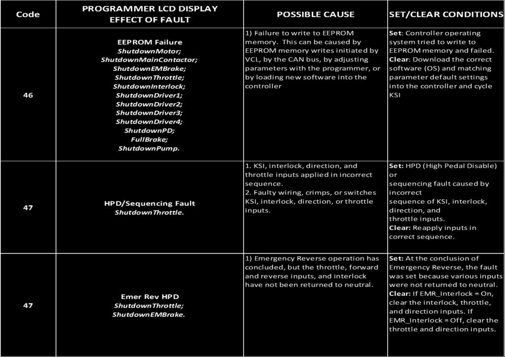
46 Code 38 PROGRAMMER LCD DISPLAY EFFECT OF FAULT Main Contactor Welded ShutdownMotor; ShutdownMainContactor; ShutdownEMBrake; ShutdownThrottle; FullBrake; ShutdownPump. POSSIBLE CAUSE 1) Main contactor tips are welded closed 2) Motor phase U or V is disconnected or open 3) An alternative voltage path (such as an external precharge resistor) is providing a current to the capacitor bank (B+ connection terminal) SET/CLEAR CONDITIONS Set: Just prior to the main contactor closing, the capacitor bank voltage (B+ connection terminal) was loaded for a short time and the voltage did not discharge Clear: Cycle KSI 39 Main Contactor Did Not Close ShutdownMotor; ShutdownMainContactor; ShutdownEMBrake; ShutdownThrottle; FullBrake; ShutdownPump. 1) Main contactor did not close 2) Main contactor tips are oxidized, burned, or not making good contact 3) External load on capacitor bank (B+ connection terminal) that prevents capacitor bank from charging 4) Blown B+ fuse Set: With the main contactor commanded closed, the capacitor bank voltage (B+ connection terminal) did not charge to B+ Clear: Cycle KSI 41 Throttle Wiper High ShutdownThrottle. 1) See Monitor Menu >> Inputs: Throttle Pot 2) Throttle pot wiper voltage too high Set: Throttle pot wiper (pin 16) voltage is higher than the high fault threshold (can be changed with the VCL function Setup_Pot_Faults() ) Clear: Bring throttle pot wiper voltage below the fault threshold 42 Throttle Wiper Low ShutdownThrottle. 1) See Monitor Menu >> Inputs: Throttle Pot 2) Throttle pot wiper voltage too low Set: Throttle pot wiper (pin 16) voltage is lower than the low fault threshold (can be changed with the VCL function Setup_Pot_Faults()) Clear: Bring throttle pot wipervoltage above the fault threshold 46
47 Code 43 PROGRAMMER LCD DISPLAY EFFECT OF FAULT Pot2 Wiper High FullBrake. POSSIBLE CAUSE 1) See Monitor Menu >> Inputs: Pot2 Raw 2) Pot2 wiper voltage too high SET/CLEAR CONDITIONS Set: Pot2 wiper (pin 17) voltage is higher than the high fault threshold (can be changed with the VCL function Setup_Pot_Faults() ) Clear: Bring Pot2 wiper voltage below the fault threshold 44 Pot2 Wiper Low FullBrake. 1) See Monitor Menu >> Inputs: Pot2 Raw 2) Pot2 wiper voltage too low Set: Pot2 wiper (pin 17) voltage is lower than the low fault threshold (can be changed with the VCL function Setup_Pot_Faults()) Clear: Bring Pot2 wiper voltage above the fault threshold 45 Pot Low Overcurrent ShutdownThrottle; FullBrake. 1) See Monitor Menu >> Outputs: Pot Low 2) Combined pot resistance connected to pot low is too low Set: Pot low (pin 18) current exceeds 10mA Clear: Clear pot low overcurrent condition and cycle KSI 47

48 48
INSTALLATION INSTRUCTIONS
 1551 S. Vineyard Avenue Ontario, CA 91761 (909) 923-1973 INSTALLATION INSTRUCTIONS E-Z-GO Installation Notes CURTIS 1234, 1236 OR 1238 AC INDUCTION MOTOR/ CONTROLLER EZ-GO Curtis Controller Installation
INSTALLATION INSTRUCTIONS
 1551 S. Vineyard Avenue Ontario, CA 91761 (909) 923-1973 INSTALLATION INSTRUCTIONS Club Car DS Installation Notes CURTIS 1234, 1236 OR 1238 AC INDUCTION MOTOR/ CONTROLLER Installation Instructions Club
INSTALLATION INSTRUCTIONS SINGLE CHANNEL ISOLATOR
 1551 S. Vineyard Avenue Ontario, CA 91761 (909) 923-1973 INSTALLATION INSTRUCTIONS SINGLE CHANNEL ISOLATOR REVISION: C 11/08/2012 INSTRUCTIONS The following instructions are meant to supplement the installation
INSTALLATION INSTRUCTIONS. Yamaha G19 Installation Notes
 620 Magnolia Avenue Suite B Ontario, CA 91762 (909) 923-1973 INSTALLATION INSTRUCTIONS Yamaha G19 Installation Notes CURTIS 1232, 1234, 1236 OR 1238 AC INDUCTION MOTOR/ CONTROLLER Yamaha G 19 Installation
620 Magnolia Avenue Suite B Ontario, CA (909) Diagnostic and Troubleshooting. Golf Cart. Revision: A Date:
 Diagnostic and Troubleshooting. Golf Cart. Revision: A Date:") 620 Magnolia Avenue Suite B Ontario, CA 91762 (909) 923-1973 Diagnostic and Troubleshooting Golf Cart Revision: A Date: 9-25-13 Diagnostics Diagnostics information can be obtained by observing the fault
620 Magnolia Avenue Suite B Ontario, CA 91762 (909) 923-1973 Diagnostic and Troubleshooting Golf Cart Revision: A Date: 9-25-13 Diagnostics Diagnostics information can be obtained by observing the fault
MANUAL. Generation 2 CURTIS INSTRUMENTS, INC. MultiMode MOTOR CONTROLLER
 MANUAL MODEL 1243 Generation 2 MultiMode MOTOR CONTROLLER 2002 CURTIS INSTRUMENTS, INC. DESIGN OF CURTIS PMC 1200 SERIES CONTROLLERS PROTECTED BY U.S. PATENT NO. 4626750. CURTIS INSTRUMENTS, INC. 200 Kisco
MANUAL. MultiMode MOTOR CONTROLLER CURTIS INSTRUMENTS, INC.
 MANUAL MODEL 1228 MultiMode MOTOR CONTROLLER 2003 CURTIS INSTRUMENTS, INC. DESIGN OF CURTIS PMC 1200 SERIES CONTROLLERS PROTECTED BY U.S. PATENT NO. 4626750. CURTIS INSTRUMENTS, INC. 200 Kisco Avenue Mount
Property of American Airlines
 MODEL CBL2000E-II MOBILE BELT CONVEYOR CHARLATTE AMERICA, INC. 600 MOUNTAIN LANE P.O. BOX 968 BLUEFIELD, VA 24605 TELEPHONE (276) 326-1510 FAX (276) 326-1602 SPARE PARTS FAX: (276) 326-3898 ONLINE: www.charlatteamerica.com
MANUAL MultiMode MOTOR CONTROLLER CURTIS PMC
 MANUAL 1244 MultiMode MOTOR CONTROLLER MODEL 2001 CURTIS INSTRUMENTS, INC. DESIGN OF CURTIS PMC 1200 SERIES CONTROLLERS PROTECTED BY U.S. PATENT NO. 4626750. CURTIS PMC 235 East Airway Boulevard Livermore,
Permanent Magnet Motor Speed Controller 1212S / 1212P / 1212C
 Motor Controllers Permanent Magnet Motor Speed Controller 1212S / 1212P / 1212C www.curtisinstruments.com 1 The Curtis Model 1212S, 1212P and 1212C Motor Speed Controllers provide efficient, optimal control
Manual Model Electric Steering Controller for Brushed PM Motor. Curtis Instruments, Inc.
 Manual Model 1220 Electric Steering Controller for Brushed PM Motor Curtis Instruments, Inc. 200 Kisco Avenue Mt. Kisco, NY 10549 www.curtisinstruments.com Read Instructions Carefully! Specifications are
Cover. L5v2 Plug-In Conversion Module(PCM) Diagnostic Trouble Codes
 Diagnostic Trouble Codes") Cover L5v2 Plug-In Conversion Module(PCM) Diagnostic Trouble Codes Copyright 2009 A123 Systems, Inc. All rights reserved DOCUMENT NOTICE: The information contained in this manual is the property of A123
Cover L5v2 Plug-In Conversion Module(PCM) Diagnostic Trouble Codes Copyright 2009 A123 Systems, Inc. All rights reserved DOCUMENT NOTICE: The information contained in this manual is the property of A123
CURTIS AC Motor Controller Parameter List Model:
 Multimode Functions M1 Forward Max Speed 3000 0 8000 rpm User User M2 Forward Max Speed 3000 0 8000 rpm User User M1 Reverse Max Speed 3000 0 8000 rpm User User M2 Reverse Max Speed 3000 0 8000 rpm User
Aftermarket Interface Module
 An ISO 9001:2008 Registered Company Aftermarket Interface Module (2015-2018 Ford Transit) AIM514-B High Side Solenoid type Coolant Valve Control AIM515-B Motor Reversing type Coolant Valve Control Introduction
CURTIS INSTRUMENTS, INC. MultiMode MOTOR CONTROLLERS
 12 2 3 / 3 3 1 2 2 5 / 3 5 1 2 2 7 / 3 7 MultiMode MOTOR CONTROLLERS 2011 CURTIS INSTRUMENTS, INC. 1223/33, 1225/35, 1227/37 Manual p/n 16879, Rev. D: May 2011 CURTIS INSTRUMENTS, INC. 200 Kisco Avenue
MANUAL. MultiMode MOTOR CONTROLLER CURTIS INSTRUMENTS, INC.
 1210 MANUAL MODEL 1210 MultiMode MOTOR CONTROLLER 2004 CURTIS INSTRUMENTS, INC. DESIGN OF CURTIS PMC 1200 SERIES CONTROLLERS PROTECTED BY U.S. PATENT NO. 4626750. 1210 Manual, p/n 37278 Rev. A: January
Instructions for Throttle & Battery Filling Pump Set Up
 620 Magnolia Avenue Suite B Ontario, CA 91762 (909) 923-1973 Instructions for Throttle & Battery Filling Pump Set Up Version: 800 After March 2007 with Version 8.00U Software Instructions for Throttle
1236/38 Manual CURTIS INSTRUMENTS, INC. AC INDUCTION MOTOR CONTROLLERS with VCL
 1236/38 Manual 1236 & 1238 MODELS AC INDUCTION MOTOR CONTROLLERS with VCL 2005 CURTIS INSTRUMENTS, INC. DESIGN OF CURTIS PMC 1200 SERIES CONTROLLERS PROTECTED BY U.S. PATENT NO. 4626750. 1236/38 Manual,
Idle Timer Controller - ITC515-A Ford Transit Contact InterMotive for additional vehicle applications
 An ISO 9001:2008 Registered Company Idle Timer Controller - ITC515-A 2015-2018 Ford Transit Contact InterMotive for additional vehicle applications Overview The ITC515-A system will shut off gas or diesel
Idle Timer Controller - ITC Freightliner MT45 Contact InterMotive for additional vehicle applications
 An ISO 9001:2008 Registered Company System Operation Idle Timer Controller - ITC805 2013-2018 Freightliner MT45 Contact InterMotive for additional vehicle applications The ITC805 system shuts down idling
ECO3-601/602 EcoStar III * Chevy Express/GMC Savana Contact Intermotive for additional vehicle applications
 An ISO 9001:2015 Registered Company ECO3-601/602 EcoStar III 2009-2019* Chevy Express/GMC Savana Contact Intermotive for additional vehicle applications * In 2017-2018, the ignition switches on Chevy Express
Wiring & Installation Manual
 www.orionbms.com Wiring & Installation Manual The Orion BMS 2 by Ewert Energy Systems is the second generation of the Orion BMS. The Orion BMS 2 is designed to manage and protect lithium ion battery packs
ITCEMS950 Idle Timer Controller - Engine Monitor Shutdown Isuzu NPR 6.0L Gasoline Engine
 Introduction An ISO 9001:2008 Registered Company ITCEMS950 Idle Timer Controller - Engine Monitor Shutdown 2014-2016 Isuzu NPR 6.0L Gasoline Engine Contact InterMotive for additional vehicle applications
MANUAL 1207& 1207A CURTIS PMC. MultiMode MOTOR CONTROLLERS
 MANUAL 1207& 1207A MultiMode MOTOR CONTROLLERS 1999 CURTIS INSTRUMENTS, INC. DESIGN OF CURTIS PMC 1200 SERIES CONTROLLERS PROTECTED BY U.S. PATENT NO. 4626750. CURTIS PMC 235 East Airway Boulevard Livermore,
1253 HYDRAULIC PUMP MOTOR
 1253 HYDRAULIC PUMP MOTOR C O N T RO L L E R M O D E L 2011 CURTIS INSTRUMENTS, INC. 1253 Manual, p/n 38329 Rev. D: February 2011 CURTIS INSTRUMENTS, INC. 200 Kisco Avenue Mt. Kisco, New York 10549 USA
Gas Spreader PLUS Remote Kit With Built in Clutch Relay and On/Off Switch
 Gas Spreader PLUS Remote Kit With Built in Clutch Relay and On/Off Switch NOTE: Read all directions first before continuing. This wireless controller kit has been programmed and tested before shipping.
MANUAL / / / 3 7 MultiMode MOTOR CONTROLLERS CURTIS PMC
 MANUAL 12 2 3 / 3 3 12 2 5 / 3 5 12 2 7 / 3 7 MultiMode MOTOR CONTROLLERS 2000 CURTIS INSTRUMENTS, INC. DESIGN OF CURTIS PMC 1200 SERIES CONTROLLERS PROTECTED BY U.S. PATENT NO. 4626750. CURTIS PMC 235
WARRANTY WILL BE VOID If These Steps are Not Performed Before Installing The Control STEPS TO PERFORM BEFORE CONTROL INSTALLATION
 Curtis 1268-5411 This sheet is provided to aid in the installation of your remanufactured CURTIS controller. Upon installation, you may encounter problems that may, or may not, be due to a faulty controller.
1234/36/38 Manual CURTIS INSTRUMENTS, INC. M O D E L S. AC INDUCTION MOTOR CONTROLLERS OS 11 with VCL
 1234/36/38 Manual 1234 1236 & 1238 M O D E L S AC INDUCTION MOTOR CONTROLLERS OS 11 with VCL 2008 CURTIS INSTRUMENTS, INC. DESIGN OF CURTIS PMC 1200 SERIES CONTROLLERS PROTECTED BY U.S. PATENT NO. 4626750.
Fincor DC Drives. Flexible & Powerful TYPICAL APPLICATIONS. Conveyor Rugged. Extruder Reliable. Conveyor Simple. Mixer Flexible
 DC Drives Flexible & Powerful single-phase DC drives provide a complete family solution from the compact Series 2120 chassis drive to the powerful Series 2230 and it s feature rich application specific
Programmable 8 Channel Injector Driver Module
 Overview: Programmable 8 Channel Injector Driver Module 554-142 The 8 channel fuel injector driver module allows for an input signal from any ECU to be changed into a user selectable peak and hold current.
Idle Timer Controller - A-ITC520-A Ford E Series Ford F250 - F Ford F250 - F550 (*B-ITC520-A) F650/F750
 F650/F750") An ISO 9001:2008 Registered Company Idle Timer Controller - A-ITC520-A 2009-2018 Ford E Series 2008-2016 Ford F250 - F550 2017-2018 Ford F250 - F550 (*B-ITC520-A) 2016-2018 F650/F750 *Uses the Ford 24-Pin
An ISO 9001:2008 Registered Company Idle Timer Controller - A-ITC520-A 2009-2018 Ford E Series 2008-2016 Ford F250 - F550 2017-2018 Ford F250 - F550 (*B-ITC520-A) 2016-2018 F650/F750 *Uses the Ford 24-Pin
MOTOR CONTROLLER CURTIS INSTRUMENTS, INC. 200 Kisco Avenue Mt. Kisco, New York USA Tel Fax
 M O D E L 1266 MOTOR CONTROLLER 2006 CURTIS INSTRUMENTS, INC. DESIGN OF CURTIS 1200 SERIES CONTROLLERS PROTECTED BY U.S. PATENT NO. 4626750. 1266 Manual, p/n 38228 Rev. A: October 2006 CURTIS INSTRUMENTS,
INSTALLATION INSTRUCTION
 1551 S. Vineyard Avenue Ontario, CA 91761 (909) 923-1973 INSTALLATION INSTRUCTION Club Car Precedent Installation Notes CURTIS 1234, 1236 OR 1238 AC INDUCTION MOTOR/ CONTROLLER REVISION: B This kit is
INSTALLATION GUIDE. FCC ID NOTICE
 REV.5 RS. ADVANCED REMOTE STARTER INSTALLATION GUIDE www.security.soundstream.com FCC ID NOTICE This device complies with Part 5 of the FCC rules. Operation is subject to the following conditions:. This
Manual Model Permanent Magnet Motor Speed Controller. Curtis Instruments, Inc. 200 Kisco Avenue Mt. Kisco, NY
 Manual Model 1229 Permanent Magnet Motor Speed Controller Curtis Instruments, Inc. 200 Kisco Avenue Mt. Kisco, NY 10549 www.curtisinstruments.com Read Instructions Carefully! Specifications are subject
SYMPTOM POSSIBLE CAUSES CORRECTIVE ACTION. Batteries Battery connections
 ELECTRICAL SYSTEM AND TESTING TROUBLESHOOTING GUIDE 2 Troubleshooting 11 TROUBLESHOOTING GUIDE 2 SYMPTOM POSSIBLE CAUSES CORRECTIVE ACTION Vehicle does not operate Batteries Batteries discharged Charge
GTWY605 Fast Idle, Shift Interlock, I/O Chevy 610 Van - 6.0L and 6.6L Engines Contact InterMotive for additional vehicle applications.
 An ISO 9001:2008 Registered Company GTWY605 Fast Idle, Shift Interlock, I/O 2009-2017 Chevy 610 Van - 6.0L and 6.6L Engines Contact InterMotive for additional vehicle applications. Introduction The Gateway
GTWY515, GTWY516* Fast Idle, Shift Interlock, I/O Ford Transit Introduction
 An ISO 9001:2015 Registered Company GTWY515, GTWY516* Fast Idle, Shift Interlock, I/O 2015-2019 Ford Transit Introduction The Gateway 515 and 516 are wheelchair lift safety interlocks which allows lift
ELECTRIC SCHEMATICS LS1 LS2. "1532ES / 1932ES" Service & Parts Manual - ANSI Specifications March 2008 Page 5-9 ART_2236 ART_2243
 ELECTRIC SCHEMATICS NOTES: (Unless otherwise specified). Switch S BASE/PLATFORM makes contact from the CENTER to the LEFT position when placed in BASE.. Switch S UP/DOWN makes contact from the CENTER to
DTC P0A04 - Open Wiring Fault
 DTC P0A04 - Open Wiring Fault Orion Product Orion BMS [Original] (24-180 Cell) Orion BMS 2 (24-180 Cell) Orion JR (16 Cell) Fault Supported YES YES YES FAULT DESCRIPTION This fault is a serious code that
SPEED SHIFT/TWO-STEP MODULE INSTALLATION MANUAL
 SPEED SHIFT/TWO-STEP MODULE INSTALLATION MANUAL ALTHOUGH THIS PRODUCT HAS BEEN THOROUGHLY TESTED KPIERSON TECHNOLOGIES ASSUMES NO RESPONSIBILITY FOR ANY DAMAGE THAT MAY RESULT BY THE INSTALLATION OF THIS
Alarms & Remote Start
 Alarms & Remote Start INSTALL GUIDE DOCUMENT NUMBER 809 REVISION DATE 0608 FIRMWARE COL-AL(RS)-VW6-[OL-MDB-ALL] HARDWARE OL-MDB-ALL ACCESSORIES OL-LOADER (REQUIRED) OMEGA-CARLINK-GPS (OPTIONAL) NOTICE
INSTALLATION INFORMATION
 INSTALLATION INFORMATION BMS ZE6000i-PCBT.xxxx / ver. 2 Programmable battery management system for Lithium Ion battery cells, for up to 32 round or prismatic cells, 10 to 400Ah NOTE: This installation
D&D Motor Systems, Inc.
 D&D Motor Systems, Inc. Programmable Regen Controller Manual & Schematics BE ADVISED, D&D Motor Systems, Inc. does not design and manufacture controllers. We provide them as an extension to our existing
INSTALL GUIDE OEM-AL(RS)-TL7-[FLCAN]-EN
![INSTALL GUIDE OEM-AL(RS)-TL7-[FLCAN]-EN](/thumbs/94/120615368.jpg "INSTALL GUIDE OEM-AL(RS)-TL7-[FLCAN]-EN") INSTALL GUIDE DOCUMENT NUMBER 545 REVISION DATE 08098 FIRMWARE OEM-AL(RS)-TL7-[FLCAN] HARDWARE FLCAN ACCESSORIES FLPROG (REQUIRED) TERMS OF USE: Automotive Data Solutions Inc. ( ADS ) products are strictly
INSTALL GUIDE DOCUMENT NUMBER 545 REVISION DATE 08098 FIRMWARE OEM-AL(RS)-TL7-[FLCAN] HARDWARE FLCAN ACCESSORIES FLPROG (REQUIRED) TERMS OF USE: Automotive Data Solutions Inc. ( ADS ) products are strictly
An ISO 9001:2008 Registered Company
 Introduction An ISO 9001:2008 Registered Company GTWY506 Fast Idle, Shift Interlock, I/O 2011-2016 Ford F250-F550 2017 Ford F250-F550 (Uses the Ford 24-Pin Data Link Harness) 2016-2017 Ford F650/750* *Transmission
2 WAY REMOTE STARTER & ALARM SYSTEM INSTALLATION GUIDE FCC ID NOTICE
 REV. ARS. WAY REMOTE STARTER & ALARM SYSTEM INSTALLATION GUIDE FCC ID NOTICE This device complies with Part 5 of the FCC rules. Operation is subject to the following conditions:. This device may not cause
TSX. Separately Excited Motor Controller User Guide
 TSX Separately Excited Motor Controller User Guide Navitas Technologies Ltd. C-855 Trillium Drive, Kitchener, Ontario N2R 1J9 Canada Phone: 1-519-725-7871 Fax: 1-519-725-1645 www.navitastechnologies.com
Elite Power Solutions Automatic Battery Control (ABC) Operation Manual
 Operation Manual") Elite Power Solutions Automatic Battery Control (ABC) Operation Manual Elite Power Solutions 335 E Warner Rd. STE 3 Chandler, AZ 85225 www.elitepowersolutions.com ABC Operation Manual Page 1 Table of Contents
Elite Power Solutions Automatic Battery Control (ABC) Operation Manual Elite Power Solutions 335 E Warner Rd. STE 3 Chandler, AZ 85225 www.elitepowersolutions.com ABC Operation Manual Page 1 Table of Contents
Overview of operation modes
 Overview of operation modes There are three main operation modes available. Any of the modes can be selected at any time. The three main modes are: manual, automatic and mappable modes 1 to 4. The MapDCCD
Idle Timer Controller - A-ITC620-A Chevrolet Express/GMC Savana
 Introduction An ISO 9001:2015 Registered Company Idle Timer Controller - A-ITC620-A1 2009-2019 Chevrolet Express/GMC Savana Contact InterMotive for additional vehicle applications The A-ITC620-A1 is an
AC Induction Motor Controller with VCL
 Motor Controllers AC Induction Motor Controller with VCL www.curtisinstruments.com 1 The Ultimate Class III Truck Control System: Superb Performance and Value This new AC induction motor controller (inverter)
Alarms & Remote Start
 Alarms & Remote Start INSTALL GUIDE DOCUMENT NUMBER 80 REVISION DATE 008 FIRMWARE OEM-AL(RS)-VW-[OL-MDB-ALL] HARDWARE OL-MDB-ALL ACCESSORIES OL-LOADER (REQUIRED) NOTICE The manufacturer will accept no
2122H. Arm Field Arm Field 1/8-1/ / /8-1/ / / /
 Non-Regen Drives Non-regenerative drives are typically used on applications which primarily motor in one direction and stopping is achieved through friction or infrequent use of a dynamic braking resistor.
INSTALL GUIDE OEM-AL(RS)-TL2-[FLCAN]-EN
![INSTALL GUIDE OEM-AL(RS)-TL2-[FLCAN]-EN](/thumbs/93/113120747.jpg "INSTALL GUIDE OEM-AL(RS)-TL2-[FLCAN]-EN") INSTALL GUIDE OEM-AL(RS)-TL-[FLCAN]-EN DOCUMENT NUMBER 5364 REVISION DATE 08098 FIRMWARE OEM-AL(RS)-TL-[FLCAN] HARDWARE FLCAN ACCESSORIES FLPROG (REQUIRED) TERMS OF USE: Automotive Data Solutions Inc.
INSTALL GUIDE OEM-AL(RS)-TL-[FLCAN]-EN DOCUMENT NUMBER 5364 REVISION DATE 08098 FIRMWARE OEM-AL(RS)-TL-[FLCAN] HARDWARE FLCAN ACCESSORIES FLPROG (REQUIRED) TERMS OF USE: Automotive Data Solutions Inc.
INSTALLATION INSTRUCTIONS. Revision 3.1.1
 INSTALLATION INSTRUCTIONS Revision 3.1.1 Table of Contents INTRODUCTION... 4 INSTALLATION OVERVIEW... 5 Included Parts... 6 DEVICE WIRING... 7 Required Parts... 7 Guidelines... 7 Wiring Diagram... 8 Compatible
SMM601-B Surveillance Mode Module Chevy Tahoe SSV and PPV (U.S. Vehicle Only) 2017* Chevy Tahoe PPV Only (U.S.
 2017* Chevy Tahoe PPV Only (U.S.") An ISO 9001:2008 Registered Company SMM601-B Surveillance Mode Module 2015-2016 Chevy Tahoe SSV and PPV (U.S. Vehicle Only) 2017* Chevy Tahoe PPV Only (U.S. Vehicle Only) * The SMM601 will only work properly
An ISO 9001:2008 Registered Company SMM601-B Surveillance Mode Module 2015-2016 Chevy Tahoe SSV and PPV (U.S. Vehicle Only) 2017* Chevy Tahoe PPV Only (U.S. Vehicle Only) * The SMM601 will only work properly
Section 55 Chapter 6
 Section 55 Chapter 6 REMOTE HYDRAULICS CONTROLLER Calibration and Fault Codes 6-12880NH TABLE OF CONTENTS REMOTE HYDRAULICS CONTROLLER CALIBRATION... 55-5 Requirements For Calibration... 55-5 Aux Set Main
MAGPOWR Spyder-Plus-S1 Tension Control
 MAGPOWR TENSION CONTROL MAGPOWR Spyder-Plus-S1 Tension Control Instruction Manual Figure 1 EN MI 850A351 1 A COPYRIGHT All of the information herein is the exclusive proprietary property of Maxcess International,
INTERNATIONAL 3200 AND Freightliner MB
 An ISO 9001:2000 Registered Company INTERNATIONAL 3200 AND Freightliner MB55 2002-2008 Intelligent Lift Interlock System (ILIS701-D) - Installation Instructions International & MB45/55 w/allison 2000 and
Manual Models 1266 A /1266 R
 Manual Models 1266 A /1266 R Electronic Motor Controllers Curtis Instruments, Inc. 200 Kisco Avenue Mt. Kisco, NY 10549 www.curtisinstruments.com Read Instructions Carefully! Specifications are subject
J1 Plug Pin Identification
 D D8 D D D D ART_8 J 8 D D0 R R R R TB 80 D D D D D D J Plug Pin Identification PIN # WIRE # SIGNAL FUNCTION 0 INPUT Drive Reverse INPUT Drive Forward OUTPUT Brake, Decel Valve signal 8 INPUT Steer Left
PIM701 (Police Interface Module) Dodge Charger Pursuit
 Dodge Charger Pursuit") An ISO 9001:2008 Registered Company PIM701 (Police Interface Module) 2015-2017 Dodge Charger Pursuit Introduction The Police Interface Module is intended to provide Dodge Chargers with multiple desired
An ISO 9001:2008 Registered Company PIM701 (Police Interface Module) 2015-2017 Dodge Charger Pursuit Introduction The Police Interface Module is intended to provide Dodge Chargers with multiple desired
Begin to Use The New ESC: Before use the new ESC please carefully check every connections are correct or not. Yellow motor wire B Blue motor wire A
 HIMOTO ZTW Brushless Electronic Speed Control for car or truck Thank you for purchasing ZTW Brushless Electronic Speed Controller(ESC). The ZTW electronic speed control (ESC) is specifically designed for
Mitsubishi. VFD Manuals
 Mitsubishi VFD Manuals Mitsubishi D700 VFD Installation Mitsubishi FR-D700 VFD User Manual Mitsubishi D700 Parallel Braking Resistors VFD Wiring Diagram - Apollo Mitsubishi VFD to Interpreter Mitsubishi
INSTRUCTIONS FOR INSTALLING AND OPERATING THE UNIVERSAL AUTOSYNC MODEL ASPSS DUAL COMPRESSOR SEQUENCER CONSOLE S/N 1638 AND ABOVE
 COMPRESSOR 1 EMERGENCY SHUTDOWN OFF POWER ON COMP LOADED COM PRESSOR OPERATING HOURS SYSTEM PRESSURE COMPRESSOR 2 EMERGENCY SHUTDOWN OFF POWER ON COMP LOADED COM PRESSOR OPERATING HOURS LEAD/LAG CONTROL
HOLLEY VR2 FUEL PUMPS P/N & Installation Instructions 199R10975
 HOLLEY VR2 FUEL PUMPS P/N 12-3000 & 12-3000-2 Installation Instructions 199R10975 WARNING! THESE INSTRUCTIONS MUST BE READ AND FULLY UNDERSTOOD BEFORE BEGINNING INSTALLATION. FAILURE TO FOLLOW THESE INSTRUCTIONS
MB A 12V/24V DC PROGRAMMABLE DUAL BATTERY ISOLATOR
 MB-3688 120A 12V/24V DC PROGRAMMABLE DUAL BATTERY ISOLATOR User Manual Warning and Precautions MB-3688 is built with corrosion resistant material and the main electronic assembly is well sealed inside
Idle Timer Controller - A-ITC620-A Chevrolet Express/GMC Savana
 An ISO 9001:2008 Registered Company Idle Timer Controller - A-ITC620-A1 2009-2018 Chevrolet Express/GMC Savana Contact InterMotive for additional vehicle applications Introduction The A-ITC620-A1 is an
Separately Excited Electronic Motor Speed Controller Model 1243 SepEx
 Motor Controllers Separately Excited Electronic Motor Speed Controller Model 1243 SepEx www.curtisinstruments.com 1 Curtis PMC Model 1243 SepEx programmable controllers provide smooth and seamless regenerative
Table of Contents. 350 V, 80 kw, 20 kwh, traction battery pack, specifications
 350 V, 80 kw, 20 kwh, traction battery pack, specifications Table of Contents 1 Description...2 2 Block diagram...3 3 Electrical Specifications...4 Pack...4 Charger...5 DC-DC converter...5 4 Mechanical
80V 300Ah Lithium-ion Battery Pack Data Sheet
 80V 300Ah Lithium-ion Battery Pack Data Sheet 80 V, 300 amp-hour capacity, maintenance-free energy storage, IP65 design, fully integrated BMS, integrated fuse and safety relay protection, highly configurable
An ISO 9001:2008 Registered Company
 An ISO 9001:2008 Registered Company CVC501-A HVAC & Fast Idle CAN Vehicle Controller CVC502-A HVAC Control without Fast Idle 2011-2016 Ford F250-F550 (CVC501/502-A) 2017 Ford F-250-F550 (B-CVC501/502-A)
An ISO 9001:2015 Registered Company
 Introduction An ISO 9001:2015 Registered Company HL550-B Fast Idle, Lift Interlock 2011-2016 Ford F250-F550 2017-2019 Ford F250-F550 (B-HL550*) 2016-2017 Ford F650/750** *Uses the Ford 24-Pin Data Link
Figure 1: A photograph of the Synercon Technologies Smart Sensor Simulator with the 70 pin Caterpillar connectors.
 SSS-ADEM3 The Smart Sensor Simulator (SSS) for the Caterpillar ADEM A3 and ADEM 2000 ECMs (collectively known as an ADEM III) enables investigators to download HVEDR data without risk of spoiling the data
Installing the Throttle Commander Ford F250 F550 Super Duty
 Installing the Throttle Commander Ford F250 F550 Super Duty 6.0 L Power Stroke Diesel 2003.25 2004 T500082, T500083 and T500084 1.0 Preparing for Installation...5 2.0 Installing the Throttle Control Box...5
TTT802 Gearshift Controller, Part # R1N-S (Standard), -P (Paddleshift)
, -P (Paddleshift)") First, Sign and Date Bln 2009-03-9 Updated, Sign and Date Bln 200-04-29 (0) User Manual TTT802 Gearshift Controller Firmware for R--N-2- TTT802 Gearshift Controller, Part # 2-620-9-RN-S (Standard), -P
First, Sign and Date Bln 2009-03-9 Updated, Sign and Date Bln 200-04-29 (0) User Manual TTT802 Gearshift Controller Firmware for R--N-2- TTT802 Gearshift Controller, Part # 2-620-9-RN-S (Standard), -P
EPC DC MOTOR SPEED CONTROL
 EPC DC MOTOR SPEED CONTROL OPERATION AND INSTRUCTION MANUAL THIS MANUAL IS PUBLISHED BY EPC CORPORATION AND IS TO BE DISTRIBUTED ONLY WITH NEW EPC CONTROLS AND EQUIPMENT NO OTHER DISTRIBUTION IS PERMITED
INSTALLATION GUIDE Table of Contents
 CT-3100 Automatic transmission remote engine starter systems. What s included..2 INSTALLATION GUIDE Table of Contents Door lock toggle mode..... 4 Notice...2 Installation points to remember. 2 Features..2
Orion BMS Purchasing Guide Rev. 1.2
 www.orionbms.com Orion BMS Purchasing Guide Rev. 1.2 Main Components... 2 Orion BMS Unit... 2 Current Sensor... 4 Thermistors... 5 CANdapter... 6 Wiring Harnesses... 7 Cell voltage tap wiring harnesses...
SALDET SALES & SERVICE, INC. CLINTON TOWNSHIP, MICHIGAN
 Form 1254 BRAKETRON Electronic Motor Brake Instructions SALDET SALES & SERVICE, INC. CLINTON TOWNSHIP, MICHIGAN TABLE OF CONTENTS SECTION TITLE PAGE I. Introduction 1 II. Specifications 1 III. Principles
Application Engineering
 Application Engineering February, 2009 Copeland Digital Compressor Controller Introduction The Digital Compressor Controller is the electronics interface between the Copeland Scroll Digital Compressor
An ISO 9001:2008 Registered Company
 An ISO 9001:2008 Registered Company Introduction Engine Monitor System 2009-2018 Ford E Series (EMS501-D) 2008-2010 Ford F250-550 6.2L, 6.8L (EMS506-D) 2011-2016 Ford F250-550 6.2L, 6.8L (EMS507-D) 2017
MBCM-24 MULTIPLE BATTERY CHARGING MODULE (FOR MARINE APPLICATIONS) FEATURES SPECIFICATIONS APPLICATIONS DESCRIPTION & OPERATION ORDERING INFORMATION
 FEATURES SPECIFICATIONS APPLICATIONS DESCRIPTION & OPERATION ORDERING INFORMATION") FEATURES Extends the trolling motor run time by charging the trolling motor batteries each time the boat s main engine is used. Automatically senses engine s alternator charge voltage, connects trolling
FEATURES Extends the trolling motor run time by charging the trolling motor batteries each time the boat s main engine is used. Automatically senses engine s alternator charge voltage, connects trolling
Freedom egen System End-of- Line Functional Checklist
 U Freedom egen System End-of- Line Functional Checklist 976-0361-01-01 Rev A April 2018 DANGER RISK OF FIRE, ELECTRIC SHOCK, EXPLOSION, AND ARC FLASH This checklist is in addition to, and incorporates
Speed Sentinel Programmable Road Speed Limiter
 An ISO 9001:2008 Registered Company Speed Sentinel Programmable Road Speed Limiter SS531-A, SS531-AX, SS531-AND Ford E Series 2005-2012 Ford F Series 2008-2010 Ford Crown Victoria 2005-2008 Contact InterMotive
Automotive Application ET01 Software Revision A 12/06
 Automotive Application ET01 Software Revision A 12/06 INTRODUCTION... 2 FUNCTIONAL DESCRIPTION... 3 INSTALLATION... 4 COMPONENT PLACEMENT... 4 PLUMBING AND WIRING... 5 MSBC OPERATION (ET-01)... 14 TIMED
Alarms & Remote Start
 Alarms & Remote Start INSTALL GUIDE OEM-AL(RS)-CH0-[OL-MDB-ALL]-EN DOCUMENT NUMBER 990 REVISION DATE 008 FIRMWARE OEM-AL(RS)-CH0-[OL-MDB-ALL] HARDWARE OL-MDB-ALL ACCESSORIES OL-LOADER (REQUIRED) NOTICE
GTWY505 Fast Idle, Shift Interlock, I/O Ford E-Series
 An ISO 9001:2008 Registered Company GTWY505 Fast Idle, Shift Interlock, I/O 2009-2018 Ford E-Series Introduction The Gateway 505 is a wheelchair lift safety interlock which will only work with the ignition
Automotive Data Solutions Inc. Rev. Date: August 07, 2014 Doc. No.: ##15683##
 Automotive Data Solutions Inc. INSTALL GUIDE ADS-AL(DL)-CH4-EN Available for : ADS-AL CA Rev. Date: August 07, 04 Doc. No.: ##5683## CH4 Version FRançaise disponible en ligne au www.idatalink.com please
GLM SERIES CONTROL Users Manual Rev:
 GLM SERIES CONTROL Users Manual Rev: 808062 Connecting Power Page 2 Motor Terminal Wiring Diagrams Page 3 Getting Started / Setup Page 4 1. Obstruction Detection Devices Page 4 2. Checking Power and Direction
AIRSTREAM - BATTERY CONTROL CENTER - Diesel
 P/N 00-00755-000 CAUTION: The Battery Control Center is a centralized power switching, fusing, and distribution center. Power from both the chassis and coach batteries is fed into the box. The full power
Automotive Data Solutions Inc. AVAILABLE FOR : ADS-AL CA. Rev. Date: January 03, 2018 Doc. No.: ##46808##
 Automotive Data Solutions Inc. INSTALL GUIDE ADS-AL(DL)-CH4-EN AVAILABLE FOR : ADS-AL CA Rev. Date: January 03, 08 Doc. No.: ##46808## CH4 U.S. PATENT NO. 8,856,780 PLEASE VISIT WWW.IDATALINK.COM FOR COMPLETE
SYMBOL LEGEND DANGER WARNING NOTE THIS INDICATES DANGER TO THE LIFE AND HEALTH OF THE USER IS APPROPRIATE PRECAUTIONS ARE NOT TAKEN
 SYMBOL LEGEND DANGER THIS INDICATES DANGER TO THE LIFE AND HEALTH OF THE USER IS APPROPRIATE PRECAUTIONS ARE NOT TAKEN WARNING THIS WARNS THAT MATERIALS MAY BE DAMAGED IF APPROPRIATE PRECAUTIONS ARE NOT
SAVE THESE INSTRUCTIONS
 READ AND FOLLOW ALL SAFETY INSTRUCTIS! SAVE THESE INSTRUCTIS AND DELIVER TO OWNER AFTER INSTALLATI IMPORTANT SAFETY INSTRUCTIS! WARNING To reduce the risk of death, injury or property damage from fire,
HL515-B Fast Idle, Lift Interlock Ford Transit
 An ISO 9001:2008 Registered Company HL515-B Fast Idle, Lift Interlock 2015-2018 Ford Transit Introduction The HighLock 515-B is a wheelchair lift safety interlock which will only work with the ignition
Installation, Operation and Maintenance Manual
 Document 473681 Vari-Green Motor and Controls Installation, Operation and Maintenance Manual Please read and save these instructions for future reference. Read carefully before attempting to assemble,
J1 Plug Pin Identification
 D5 D8 D7 D4 D5 D ART_8 J 4 8 D D0 7 R R R R4 TB 80 D D D D4 D D J Plug Pin Identification PIN # WIRE # SIGNAL FUNCTION 0 INPUT Drive Reverse INPUT Drive Forward OUTPUT Brake, Decel Valve signal 4 8 INPUT
J1 Plug Pin Identification
 D5 D D D D5 D ART_ J D D0 R R R R TB 0 D D D D D D J Plug Pin Identification PIN # WIRE # SIGNAL FUNCTION 0 INPUT Drive Reverse INPUT Drive Forward OUTPUT Brake, Decel Valve signal INPUT Steer Left 5 OUTPUT