INSTALLATION INSTRUCTIONS
|
|
|
- Barbara Fields
- 6 years ago
- Views:
Transcription
 923-1973 INSTALLATION INSTRUCTIONS E-Z-GO")
1 1551 S. Vineyard Avenue Ontario, CA (909) INSTALLATION INSTRUCTIONS E-Z-GO Installation Notes CURTIS 1234, 1236 OR 1238 AC INDUCTION MOTOR/ CONTROLLER
2 EZ-GO Curtis Controller Installation 1. Disconnect Negative Battery Cable, Disconnect Positive Battery Cable. 2. Disconnect all Motor and Controller wires. 3. Remove original Motor, Controller & Reversing Switch (remove controllermounting plate, if equipped). 4. Remove original wiring harness. Unplug any connector s possible (cut as little as possible). If equipped with rear brake lights, label and keep factory wires from the brake pedal switch. These wires will be reused to enable the brake lights. (See DIAGRAM 2.1) 5. Install the Controller mounting plate in cart. See PICTURE 1.5. Installation of the cables and wiring harness will be outlined in later steps. 6. Bolt the Controller, ITS Converter & Solenoid to new mounting plate. Use supplied ¼-20 bolts and lock washers. 7. Install new AC 9 Motor. Use the supplied ¼-20 bolts and lock washers. Do not over torque Motor Bolts. 8. If clearance from the passenger shock mount to the motor s fan shield is less than one inch (viewing from the top), cut/trim passenger side rear. This procedure is not needed if cart has been lifted. Not required if the cart is lifted. 9. If equipped, install the on-board Battery Charger. For Delta-Q Battery Charger see Picture 1.6 and DIAGRAM 2.4 for reference. 10. Connect Motor Cables from the controller to the AC9 Motor at each appropriate phase. Motor Cables and Battery Cables should be at least #2 AWG. See Picture 1.7 and DIAGRAM 2.8 for reference. 11. Connect one side of the solenoid to the Fuse Post on the Controller. 12. Connect Negative Battery Cable to the controller. (DO NOT connect to Battery at this point). Page 2 of 20
3 13. Install Wiring Harness. Refer to DIAGRAM Use supplied cable adapter for throttle wires. Plug the flat connector into the ITS converter box. Plug 4-pin square connector into mating connector on wiring harness. Connect the Blue wire to the Blue wire on the solenoid, Red to the Red, Green to the Green, White to the White & Black to the Black on the ITS cable. 15. Connect wires to FWD/REV switch, See DIAGRAM 2.5 & 2.6. Connect the Blue wire to the center connector tab. Connect the Yellow towards F, forward and White towards R, reverse. 16. Drill a 2 1/16 hole in the dash panel for the BDI. 17. Plug cable with 8-pin connector into the back of the Dash Display. 18. Connect Red Wire to one side of Key switch. 19. Connect Blue wire to key switch. 20. Connect a Yellow wire from F & R switch to the positive side of the reverse buzzer, and the Gray wire to the negative. See DIAGRAM Connect a Blue wire from the key switch to terminal 2 on the Golf/Street switch, and the Brown wire to terminal 1. (Golf Mode is selected when terminals 1 and 2 are connected together). See DIAGRAM 2.6 & For carts equipped with Rear Brake Light Kit, install a 12VDC automotive type relay in a suitable location where both factory and system wires can be connected together. The factory brake wires were disconnected and labeled at step #4. The below connections can be reviewed by using the DIAGRAMS 2. 2, 2. 3 & Connect the factory +12V source Red wire to the relay at terminal # Connect the factory Brown wire of the rear brake lights to the Brake Relay at terminal #87. Wire color may be different depending on model year Connect a Blue wire from the key switch to the Brake Relay at terminal # Connect the Orange wire to the Brake Relay at terminal #85. Page 3 of 20
4 22.5. Connect Blue wire to the COM on the Brake Switch, Connect the purple wire to the N.C. terminal. 23. Connect White/Red wire to Menu Button. Connect other side of button to Blue wire on the key switch. See DIAGRAM Connect Orange/White wire to the (negative side of the Main Contactor), and Blue/White wire to the + (positive side). Remove any diode, resistors. 25. Connect Fuse Wire and the + Battery cable to the Main Contactor. If On Board charger is used, connect fuse wire to the Green wire from the charger. 26. Plug in Encoder Cable to the motor. 27. DOUBLE CHECK ALL CONNECTIONS. 28. Secure all wires, harnesses and cables to the cart s frame by using tie straps. 29. Install 10 Amp fuse at the fuse holder in the system harness. 30. Connect (negative) Battery Cable. 31. Test Cart on Jack Stands. There will be no motor damage if the motor initially over speed. If motor runs slow and in the wrong direction, reverse the U and W leads on the Motor. Page 4 of 20
5 Driving the car with the A-C Drive System When key switch is first turned on, the system needs about 2 seconds to come online. After this time has expired, select the desired drive direction at the Forward/Reverse switch and press the accelerator pedal. The drive wheels could be in either direction when first turned on. BDI: (Dash Gauge), the BDI will display Battery Charge level (LED s at bottom) as well as text messages. BDI Message MPH GOLF REVERSE LOWBATT Mode Cart in Street Mode (displays vehicle speed) Cart in Golf Mode (see note below) Cart in Reverse direction (see note below) Cart in Limp Home mode (see note below) Menu System: Battery Percentage: TOC: Volts: RPM: State of Charge left in batteries. Time on Charge, Time in minutes since the last time the car was charged. Battery Voltage Motor RPM The last menu option is the vehicle odometer. Street Mode gives the cart a Max speed of 25 Miles per hour. Acceleration & Regenerative Brake torque are set at maximum level. When in Golf Mode the cart speed is limited to 12 Miles per hour. Acceleration & Regenerative Brake torque is also reduced. Page 5 of 20
6 Drive Mode can be changed on The Fly. There is no need to stop the cart when changing from Street to Golf or vice-versa. When Cart is in Reverse, speed is reduced to 8 Miles per hour. Acceleration & Regenerative Braking torque is also reduced. Limp Home mode is automatically activated when the Battery charge level has dropped below 20%. The maximum cart speed is restricted up to 15 Miles per hour at Street mode. It is recommended to charge the batteries as soon as possible to prevent damage to the batteries from being over discharged. Page 6 of 20
7 Instructions for Throttle Set Up For systems set up after March 2007 with Version 8.00U software With Key OFF, Select Forward Direction, Release Parking Brake, Press and hold the Menu Button, then turn the Key ON. Hold Menu Button until Program appears on the Dash Display, then release. If the cart has a brake pedal switch: Use the Brake Pedal to cycle through the options. Have the Golf/Street Mode switch set to Street Mode, (MPH), to change parameters. If the cart does not have a brake pedal switch: Select Golf Mode and press the Menu Button to cycle through the options. To change a parameter in any of the options: Select Street Mode and press the Menu Button to change a parameter or activate an option. T Type: This is the Throttle Pot Type Parameter. For 0-to-5k, 2-wire throttle pots, set to type 3. For 3-wire throttle pots or EZ Go with ITS converter box, set to Type 2. The default is Type 2. Throttle: This allows the Throttle range to be calibrated. Cycle the program options to Throttle on the Dash Display, select Street Mode, press the Accelerator Pedal to the floor (Max Throttle). With the pedal pressed, press and hold the Menu Button and the display will show HoldMenu. Maintain the pedal and menu button pressed until the display reads Turn OFF. After this message is displayed, turn off the Key. DO NOT release the accelerator pedal or the Menu button before turning OFF the Key. The Throttle is now calibrated. Using this procedure will ensure full throttle range; if this procedure is not performed the calibration will be at to a default setting. Use this set up procedure for 2-wire, 0-to-5k, three wire throttle or EZ Go with ITS converter box types. Page 7 of 20
8 Rst: This is the BDI reset voltage per battery cell. Adjust only if there is a problem with the BDI resetting to 100% when the batteries are below 85% and have not been charged or not resetting after a charge. To increase the parameter, select Forward and Street Mode, then press the Menu button. To decrease, select Reverse and Street Mode, then press the Menu button. The default is volts per cell; this should work fine in most applications. Mode: Sets the Motor Control Mode. The control mode can be set as Mode 1 or Mode 2 Mode 1 is Speed Control. Speed Control means the accelerator pedal controls the actual speed of the vehicle. For example: In Speed Control Mode if you set the accelerator pedal to half, you will go half speed, uphill, downhill or on flat ground. Speed Mode is great if you are looking for controlled descents down hills and want to use the brakes a little as possible. It does however have more of a jerky feel when changing speeds with the accelerator pedal. Mode 2 is Torque Control Mode. Torque control is the same type of control method a DC motor has. The accelerator pedal controls the amount of torque the motor produces. This gives a much smoother feel when changing the accelerator position. Brakes will be used more in downhill descents. Brk%: Only available if the Speed Mode is set to 2. This sets the amount of Regen when the Brake Pedal is pressed. To increase the parameter, select Forward and Street Mode, then press the Menu button. To decrease, select Reverse and Street Mode, then press the Menu button. If the default braking level is desired, leave this set to Zero. The Default is 40%. So, setting to 1% would be the lowest setting and give almost no Regen. Page 8 of 20
9 Instructions for using On Board Diagnostics With the Key OFF, Select Reverse Direction, Press and hold the Menu Button. Turn Key the ON, hold Menu Button until Diagnose appears on the Dash Display, then release the Menu Button. Pressing and releasing the menu button will scroll through the Diagnostic options. The cart can be driven during diagnostic checks. T Sw: This monitors the state of the Throttle Switch. With the pedal in the idle position the display should read OFF, when the pedal is pressed the display should change to ON. If OFF is always displayed there is a problem with the switch on the throttle pedal. This test can be performed in Neutral or with either direction selected. TPV: This is the raw Throttle pot voltage. This test should be performed with the car in Neutral. 0.2 volts is normal for idle position, at full throttle, 3.5 volts for 2 wire pots, and 5.0 volts for 3 wire pots. T Max: This is what the Max Throttle Voltage Parameter is set at. For example: If the Parameter is set at 4.5, then the TPV will need to reach 4.5 for full speed to be obtained. Use the Throttle calibration procedure if adjustments are necessary. Req %: This is the amount of throttle being requested of the controller. This should be a number from 0 to 100% when the car is being driven. Brk: On or Off. Checks to ensure brake switch signal input to the controller. Should be ON when the brake pedal is pressed and OFF when the brake pedal is released. Page 9 of 20
10 CapV: This is the voltage on the Capacitor Bank inside the controller. This voltage should be at or near the voltage of the Batteries. When the Throttle is pressed, this sends a signal to the controller to pre-charge the Capacitor Bank and turn the Main Solenoid ON. If this voltage is low or at 0, this means there is probably a failure in the Pre-Charge circuit and the controller will need to be repaired or replaced. EncA & EncB: These are the Motor Encoder signals shown in RPM. This can be used to troubleshoot either an Encoder failure, or a problem in the Encoder wiring. If the motor turns slow and in the proper direction, check the RPM of both signals. If EncA has no signal, the Display will read Zero. The same applies to EncB. EncA involves with White, (sometimes Brown), wire on the encoder connector, EncB is the Green wire. On an EZGO, these colors are reversed. Main: This is the state of the Main Contactor, see table below: 0 = Open, Solenoid not turned on. 1 = Pre-charge. 2 = Weld check, the controller is checking for welded contacts. 3 = Closing Delay 5 = Closed, the Solenoid coil is energized and the contacts should be closed. 6 = Open Delay, after the cart is stopped there is a delay of about 5 seconds for the Solenoid to open. OS: This is the Version of the Operating System in the controller. Build: This is the Build number of the Operating System. Ver: This is the VCL (vehicle control language) version number. D/C: This is the date when the controller was manufactured. 6123=the 123rd day of 2006 Page 10 of 20
11 S/N: This is the unique serial number of the controller. Faults: If any, will be displayed. Fault Codes Fault codes will display on the Dash Display when they happen, the Wrench on the display will also light up. Code 12, Controller Over Current Code 13, Current sensor fault Code 14, Precharge Failure Code 16, Controller Over Temperature Code 17, Severe Undervoltage Code 18, Severe Overvoltage Code 25, 5-volt power supply failure Code 36, Encoder Fault, see diagnose, EncA & EncB. Code 37, Motor Open or Open Phase on controller fault Code 38, Main Solenoid welded Code 39, Main Solenoid not closing Code 73, Stall detected, No encoder signal, see diagnose, EncA & EncB. Page 11 of 20


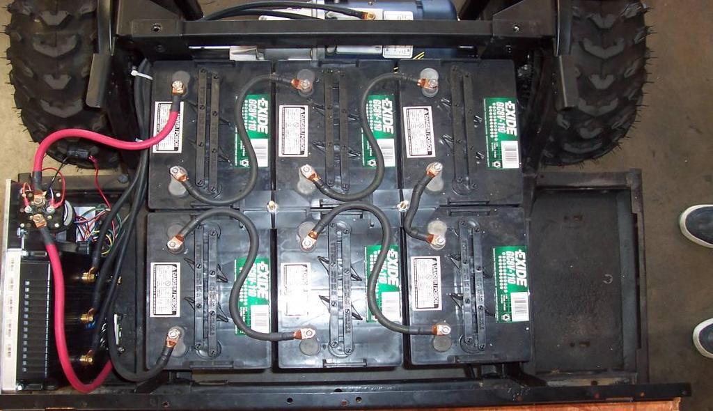
12 Picture 1.5 Picture 1.6 Picture 1.7 Page 12 of 20
13 EZ-GO FACTORY BRAKE LIGHT KIT WIRING DETAIL -DIAGRAM 2.1 BRAKE PEDAL BRAKE SWITCH BROWN RED FROM +12V BATTERY TO FACTORY BRAKE LIGHT Page 13 of 20
14 HPEV AC-9 SYSTEM BRAKE LIGHT WIRING DETAIL -DIAGRAM 2.2 BRAKE PEDAL NORMALLY CLOSED NORMALLY OPEN COMMON PURPLE BRAKE SWITCH WIRING DETAIL PURPLE (Normally Closed) BRAKE SWITCH (COMMON) HPEV SYSTEM WIRING HARNESS RED FROM +12V BATTERY DISCONNECT FACTORY BRAKE LIGHT WIRES AND RECONNECT TO A 12V AUTOMOTIVE RELAY (SEE DIAGRAM 2.3) BROWN TO FACTORY BRAKE LIGHT Page 14 of 20
15 BRAKE LIGHT REWIRING RELAY DETAIL -DIAGRAM 2.3 TO FACTORY BRAKE LIGHTS BROWN ORANGE FROM HPEV SYSTEM HARNESS FROM HPEV SYSTEM HARNESS RED BRAKE LIGHT RELAY FROM +12V BATTERY Page 15 of 20
16 EZ-GO WIRING HARNESS with ON BOARD DELTA -Q BATTERY CHARGER - DIAGRAM 2.4 FORWARD/ REVERSE SWITCH SEE DIAGRAM 2.5 WHITE RED-YELLOW YELLOW RED-YELLOW PARK SWITCH 35 PIN CONNECTOR 6 PIN PLUG TO MOTOR ENCODER WIRE BUNDLE PURPLE GREEN BLACK/ WHITE PURPLE/ WHITE YELLOW/ WHITE BRAKE SWITCH THROTTLE CONNECTIONS YELLOW GRAY BROWN ORANGE DASH PANNEL SEE DIAGRAM 2.6 RED FUSE 10A WHITE/ RED RED GREEN 8 PIN DISPLAY PLUG / WHITE + TO BATTERY POS (+) #2 CABLE ORANGE/ WHITE - Main Contactor RED BLACK WHITE BLACK - HOT WHITE - NEUTRAL GREEN - GROUND 110 VOLT AC PLUG TO CONTROLLER POS (+) MAIN FUSE #2 CABLE TO BATTERY NEG. (-) TO BATTERY POS. (+) Page 16 of 20
17 FORWARD/ REVERSE SWITCH DETAIL - DIAGRAM 2.5 FWD REV YELLOW WHITE Page 17 of 20
18 EZ-GO DASH PANEL WIRING DETAIL - DIAGRAM 2.6 YELLOW GRAY REVERSE BUZZER YELLOW WHITE FWD REV FORWARD/ REVERSE SWITCH BROWN WHITE / RED MENU BUTTON 1 2 GOLF/ STREET SWITCH RED BDI CABLE KEY SWITCH DASH DISPLAY Page 18 of 20
19 NOTICE: This drawing is the property of Hi Performance Electric Vehicle Systems Inc., and/or its subsidiaries and affiliates (individually and collectively HPEVS ), and contains highly proprietary, confidential, and trade secret information of HPEVS. The recipient of this drawing agrees (a) to use the information contained herein for the purpose for which it was furnished by HPEVS (b) to return this drawing upon HPEVS request. This notice shall appear on any complete or partial reproduction of this drawing. REVISIONS REV ORIGINATOR DESCRIPTION APPROVED C M AJOR REVISION; M ISSING DIM ENSIONING WERE ADDED 11/17/2011 R1 AMP NOTES: KSI BRAKE RELAY BACK UP BUZZER MAIN CONTACTOR COIL I/O GROUND MOTOR TEMP SENSOR PEDAL INTERLOCK MENU BUTTON BRAKE SWITCH GOLF / STREET SWITCH COIL RETURN POT HIGH POT WIPER FOWARD 12V POWER CNTRL 5V POWER CNTRL TX SERIAL RX SERIAL ENCODER PHASE A ENCODER PHASE B REVERSE TO BRAKE LIGHTS 18 AWG ORANGE 18 AWG GRAY 18 AWG PURPLE 18 AWG BRAKE LIGHTS RELAY ORANGE/ WHITE18 AWG BLACK/ 18 AWG YELLOW/ BLACK 18 AWG GREEN 18 AWG WHITE/ RED 18 AWG BROWN 18 AWG / WHITE 18 AWG BLACK/ WHITE 18 AWG YELLOW/ WHITE 18 AWG WHITE 18 AWG RED/ 18 AWG RED/WHITE 18 AWG GREY/ 18AWG GREEN/ WHITE 18 AWG TAN 18 AWG TAN/BLACK 18 AWG YELLOW 18 AWG (*1) IF REVERSE IS NOT USED, CONNECT WHITE WIRE TO WIRE. (*2) MENU BUTTON IS OPTIONAL USE WITH DISPLAY. (*3) REMOVE ANY DIODES OR RESISTOR FROM MAIN CONTACTOR. (*4) USE 400A FUSE IN 650 SYSTEM. USE 300A FUSE IN 350 SYSTEM. (*5) NORMALLY OPEN. CONTACTS MUST BE CLOSED WHEN BRAKE PEDAL IS PRESSED. (*6) MOTOR TEMP SENSOR NOT USED FOR GOLF CART APPLICATION V IN S1 POT WIPER POT HIGH I/O GROUND WHITE 18 AWG YELLOW 18 AWG YELLOW 18 AWG PEDAL INTERLOCK REVERSE 18AWG BACK UP BUZZER I/O GROUND TX SERIAL FOWARD 12V POWER CNTRL RX SERIAL RED/ WHITE 18 AWG BLACK/ 18 AWG TAN 18 AWG TAN/ BLACK 18 AWG BLACK/ 18 AWG YELLOW/ BLACK 18 AWG P4 DEUTSCH DTM-04-6P 18AWG GREEN 18 AWG R4 DEUTSCH DTM-06-6S FORWARD / REVERSE SWITCH (NOTE *1) P2 MOLEX MINI FIT JR YELLOW/ WHITE 18 AWG BLACK/ WHITE 18 AWG BLACK/ 18 AWG BLACK 22 AWG S2 BLACK/ 18 AWG GREY/ 18AWG RED/ 18 AWG PURPLE 22 AWG R2 MOLEX MINI FIT JR GREEN/ WHITE 18 AWG RED/ WHITE 22 AWG BLACK/ 22 AWG TAN 22AWG TAN/ BLACK 22 AWG MOTOR ENCODER CABLE BRAKE SWITCH (NOTE *5) DISPLAY 18 AWG WHITE 18 AWG BLACK 18 AWG KSI R3 MOLEX MINI FIT JR Note: Pins 2, 3, 4, & 7 are not connected R5 MOLEX SL SERIES GREEN 18 AWG RED 18 AWG ITS CONVERTER MOTOR ENCODER MOTOR TEMP SENSOR (NOTE *6) 18AWG MENU BUTTON (NOTE *2) GOLF / STREET SWITCH WHITE 18 AWG BLACK 18 AWG W V U MOTOR 18AWG 18AWG ORANGE/ WHITE18 AWG / WHITE 18 AWG 18 AWG ITS THROTTLE UNIT HPEVS SYSTEM WIRING DETAIL - DIAGRAM 2.7 ITS KEY SWITCH CAD TYPE CAD LOC. CAD FILE VISIO OPER. NO. UNIT DRAWING DESIGN 35 PIN CONNECTOR (SEE R1) CHECKED 10A +A1 -A2 DETAIL W SAFETY +48V OR 72V RED 18AWG MAIN CONTACTOR (NOTE *3) B - B + V TITTLE U SCALE DATE REVISION C NONE 12/21/10 SHEET 1 OF A (NOTE *4) 1010-EZ-GO EZ-GO GOLF CART SYSTEM SCHEMATICS Page 19 of 20 DRW SIZE B HPEVS
20 HIGH CURRENT WIRING DETAIL - DIAGRAM 2.8 FRONT OF CART CONTROLLER U V W Main Contactor FUSE B + B - 35 PIN CONNECTOR + - ORANGE/ WHITE / WHITE V U W MOTOR 6 PIN TO WIRING HARNESS Page 20 of 20
INSTALLATION INSTRUCTIONS
 1551 S. Vineyard Avenue Ontario, CA 91761 (909) 923-1973 INSTALLATION INSTRUCTIONS Club Car DS Installation Notes CURTIS 1234, 1236 OR 1238 AC INDUCTION MOTOR/ CONTROLLER Installation Instructions Club
INSTALLATION INSTRUCTIONS. Yamaha G19 Installation Notes
 620 Magnolia Avenue Suite B Ontario, CA 91762 (909) 923-1973 INSTALLATION INSTRUCTIONS Yamaha G19 Installation Notes CURTIS 1232, 1234, 1236 OR 1238 AC INDUCTION MOTOR/ CONTROLLER Yamaha G 19 Installation
Instructions for Throttle & Battery Filling Pump Set Up
 620 Magnolia Avenue Suite B Ontario, CA 91762 (909) 923-1973 Instructions for Throttle & Battery Filling Pump Set Up Version: 800 After March 2007 with Version 8.00U Software Instructions for Throttle
Electrical Schematics and Documentation
 1551 S. Vineyard Avenue Ontario, CA 91761 (909) 923-1973 Electrical Schematics and Documentation FOR CURTIS 1232-1238 E AND SE VERSION CONTROLLERS SOFTWARE VERSIONS 5.32 AND HIGHER FOR SINGLE AND DUAL
INSTALLATION INSTRUCTIONS SINGLE CHANNEL ISOLATOR
 1551 S. Vineyard Avenue Ontario, CA 91761 (909) 923-1973 INSTALLATION INSTRUCTIONS SINGLE CHANNEL ISOLATOR REVISION: C 11/08/2012 INSTRUCTIONS The following instructions are meant to supplement the installation
620 Magnolia Avenue Suite B Ontario, CA (909) Diagnostic and Troubleshooting. Golf Cart. Revision: A Date:
 Diagnostic and Troubleshooting. Golf Cart. Revision: A Date:") 620 Magnolia Avenue Suite B Ontario, CA 91762 (909) 923-1973 Diagnostic and Troubleshooting Golf Cart Revision: A Date: 9-25-13 Diagnostics Diagnostics information can be obtained by observing the fault
620 Magnolia Avenue Suite B Ontario, CA 91762 (909) 923-1973 Diagnostic and Troubleshooting Golf Cart Revision: A Date: 9-25-13 Diagnostics Diagnostics information can be obtained by observing the fault
INSTALLATION INSTRUCTION
 1551 S. Vineyard Avenue Ontario, CA 91761 (909) 923-1973 INSTALLATION INSTRUCTION Club Car Precedent Installation Notes CURTIS 1234, 1236 OR 1238 AC INDUCTION MOTOR/ CONTROLLER REVISION: B This kit is
Property of American Airlines
 MODEL CBL2000E-II MOBILE BELT CONVEYOR CHARLATTE AMERICA, INC. 600 MOUNTAIN LANE P.O. BOX 968 BLUEFIELD, VA 24605 TELEPHONE (276) 326-1510 FAX (276) 326-1602 SPARE PARTS FAX: (276) 326-3898 ONLINE: www.charlatteamerica.com
Idle Timer Controller - ITC515-A Ford Transit Contact InterMotive for additional vehicle applications
 An ISO 9001:2008 Registered Company Idle Timer Controller - ITC515-A 2015-2018 Ford Transit Contact InterMotive for additional vehicle applications Overview The ITC515-A system will shut off gas or diesel
D&D Motor Systems, Inc.
 D&D Motor Systems, Inc. Programmable Regen Controller Manual & Schematics BE ADVISED, D&D Motor Systems, Inc. does not design and manufacture controllers. We provide them as an extension to our existing
ITCEMS950 Idle Timer Controller - Engine Monitor Shutdown Isuzu NPR 6.0L Gasoline Engine
 Introduction An ISO 9001:2008 Registered Company ITCEMS950 Idle Timer Controller - Engine Monitor Shutdown 2014-2016 Isuzu NPR 6.0L Gasoline Engine Contact InterMotive for additional vehicle applications
SYMPTOM POSSIBLE CAUSES CORRECTIVE ACTION. Batteries Battery connections
 ELECTRICAL SYSTEM AND TESTING TROUBLESHOOTING GUIDE 2 Troubleshooting 11 TROUBLESHOOTING GUIDE 2 SYMPTOM POSSIBLE CAUSES CORRECTIVE ACTION Vehicle does not operate Batteries Batteries discharged Charge
Separately Excited Electronic Motor Speed Controller Model 1266 A/R SepEx
 Motor Controllers Separately Excited Electronic Motor Speed Controller Model 1266 A/R SepEx www.curtisinstruments.com 1 Curtis Model 1266 A/R SepEx controllers are programmable and microprocessor based,
Idle Timer Controller - A-ITC520-A Ford E Series Ford F250 - F Ford F250 - F550 (*B-ITC520-A) F650/F750
 F650/F750") An ISO 9001:2008 Registered Company Idle Timer Controller - A-ITC520-A 2009-2018 Ford E Series 2008-2016 Ford F250 - F550 2017-2018 Ford F250 - F550 (*B-ITC520-A) 2016-2018 F650/F750 *Uses the Ford 24-Pin
An ISO 9001:2008 Registered Company Idle Timer Controller - A-ITC520-A 2009-2018 Ford E Series 2008-2016 Ford F250 - F550 2017-2018 Ford F250 - F550 (*B-ITC520-A) 2016-2018 F650/F750 *Uses the Ford 24-Pin
Idle Timer Controller - ITC Freightliner MT45 Contact InterMotive for additional vehicle applications
 An ISO 9001:2008 Registered Company System Operation Idle Timer Controller - ITC805 2013-2018 Freightliner MT45 Contact InterMotive for additional vehicle applications The ITC805 system shuts down idling
MANUAL 1207& 1207A CURTIS PMC. MultiMode MOTOR CONTROLLERS
 MANUAL 1207& 1207A MultiMode MOTOR CONTROLLERS 1999 CURTIS INSTRUMENTS, INC. DESIGN OF CURTIS PMC 1200 SERIES CONTROLLERS PROTECTED BY U.S. PATENT NO. 4626750. CURTIS PMC 235 East Airway Boulevard Livermore,
MANUAL. MultiMode MOTOR CONTROLLER CURTIS INSTRUMENTS, INC.
 MANUAL MODEL 1228 MultiMode MOTOR CONTROLLER 2003 CURTIS INSTRUMENTS, INC. DESIGN OF CURTIS PMC 1200 SERIES CONTROLLERS PROTECTED BY U.S. PATENT NO. 4626750. CURTIS INSTRUMENTS, INC. 200 Kisco Avenue Mount
ELECTRIC SCHEMATICS LS1 LS2. "1532ES / 1932ES" Service & Parts Manual - ANSI Specifications March 2008 Page 5-9 ART_2236 ART_2243
 ELECTRIC SCHEMATICS NOTES: (Unless otherwise specified). Switch S BASE/PLATFORM makes contact from the CENTER to the LEFT position when placed in BASE.. Switch S UP/DOWN makes contact from the CENTER to
WARRANTY WILL BE VOID If These Steps are Not Performed Before Installing The Control STEPS TO PERFORM BEFORE CONTROL INSTALLATION
 Curtis 1268-5411 This sheet is provided to aid in the installation of your remanufactured CURTIS controller. Upon installation, you may encounter problems that may, or may not, be due to a faulty controller.
Club Car IQ Technical Information Updated
 Club Car IQ Technical Information Updated 6-2-17 Begin GENERAL WIRING DIAGRAM Next TECHNICAL ASSISTANCE Solenoid Does Not Close Solenoid Closes But No Travel Vehicle Travels in reverse when in forward
Idle Timer Controller - A-ITC620-A Chevrolet Express/GMC Savana
 An ISO 9001:2008 Registered Company Idle Timer Controller - A-ITC620-A1 2009-2018 Chevrolet Express/GMC Savana Contact InterMotive for additional vehicle applications Introduction The A-ITC620-A1 is an
Idle Timer Controller - A-ITC620-A Chevrolet Express/GMC Savana
 Introduction An ISO 9001:2015 Registered Company Idle Timer Controller - A-ITC620-A1 2009-2019 Chevrolet Express/GMC Savana Contact InterMotive for additional vehicle applications The A-ITC620-A1 is an
MANUAL. MultiMode MOTOR CONTROLLER CURTIS INSTRUMENTS, INC.
 1210 MANUAL MODEL 1210 MultiMode MOTOR CONTROLLER 2004 CURTIS INSTRUMENTS, INC. DESIGN OF CURTIS PMC 1200 SERIES CONTROLLERS PROTECTED BY U.S. PATENT NO. 4626750. 1210 Manual, p/n 37278 Rev. A: January
MANUAL. Generation 2 CURTIS INSTRUMENTS, INC. MultiMode MOTOR CONTROLLER
 MANUAL MODEL 1243 Generation 2 MultiMode MOTOR CONTROLLER 2002 CURTIS INSTRUMENTS, INC. DESIGN OF CURTIS PMC 1200 SERIES CONTROLLERS PROTECTED BY U.S. PATENT NO. 4626750. CURTIS INSTRUMENTS, INC. 200 Kisco
J1 Plug Pin Identification
 D D8 D D D D ART_8 J 8 D D0 R R R R TB 80 D D D D D D J Plug Pin Identification PIN # WIRE # SIGNAL FUNCTION 0 INPUT Drive Reverse INPUT Drive Forward OUTPUT Brake, Decel Valve signal 8 INPUT Steer Left
Installing the FX302 into the E-Z-GO DCS Golf Car
 Installing the FX302 into the E-Z-GO DCS Golf Car 1015 Harrisburg Pike Carlisle, PA 17013 Phone: (717) 254-3747, Fax: (717) 254-3777 Website: www.fsip.biz Note: To prevent draining the batteries prematurely,
Aftermarket Interface Module
 An ISO 9001:2008 Registered Company Aftermarket Interface Module (2015-2018 Ford Transit) AIM514-B High Side Solenoid type Coolant Valve Control AIM515-B Motor Reversing type Coolant Valve Control Introduction
Separately Excited Electronic Motor Speed Controller Model 1243 SepEx
 Motor Controllers Separately Excited Electronic Motor Speed Controller Model 1243 SepEx www.curtisinstruments.com 1 Curtis PMC Model 1243 SepEx programmable controllers provide smooth and seamless regenerative
Club Car 1515 to Curtis 1268 Conversion
 Club Car 1515 to Curtis 1268 Conversion Installation Instructions 62-12685501CKXI Rev. 03 4/17/14 Page 1 of 7 1515 to Curtis 1268 Conversion Installation Instructions Before you start turn Tow/Run switch
J1 Plug Pin Identification
 D5 D D D D5 D ART_ J D D0 R R R R TB 0 D D D D D D J Plug Pin Identification PIN # WIRE # SIGNAL FUNCTION 0 INPUT Drive Reverse INPUT Drive Forward OUTPUT Brake, Decel Valve signal INPUT Steer Left 5 OUTPUT
MANUAL MultiMode MOTOR CONTROLLER CURTIS PMC
 MANUAL 1244 MultiMode MOTOR CONTROLLER MODEL 2001 CURTIS INSTRUMENTS, INC. DESIGN OF CURTIS PMC 1200 SERIES CONTROLLERS PROTECTED BY U.S. PATENT NO. 4626750. CURTIS PMC 235 East Airway Boulevard Livermore,
Manual Models 1266 A /1266 R
 Manual Models 1266 A /1266 R Electronic Motor Controllers Curtis Instruments, Inc. 200 Kisco Avenue Mt. Kisco, NY 10549 www.curtisinstruments.com Read Instructions Carefully! Specifications are subject
Small Full Bridge Permanent Magnet Motor DC Controller User Manual
 Small Full Bridge Permanent Magnet Motor DC Controller User Manual SPM24051X SPM24101X SPM24121X SPM48051X SPM48101X SPM48121X SPM72051X SPM72101X SPM72121X SPM48151E SPM48181E SPM48221E SPM72151E SPM72181E
Application Engineering
 Application Engineering March 2011 Copeland Digital Compressor Controller Introduction The Digital Compressor Controller is the electronics interface between the Copeland Scroll Digital compressor or the
SECOND GENERATION Use this guide with unit serial number prefix beginning with BWF using Terra Power separator.
 Technical Information and Diagnostic Guide for SECOND GENERATION Use this guide with unit serial number prefix beginning with BWF using Terra Power separator. This guide will assist you in becoming more
ION-01-6 PERFORMANCE SPEEDOMETER/TACHOMETER COMBO
 ION-01-6 PERFORMANCE SPEEDOMETER/TACHOMETER COMBO MOUNTING: It should be inserted into the opening from the front and the L-clamps will be installed from the back. Tighten the nuts on the L-clamps so that
Kelly KDC Series/PM Motor Controller User s Manual
 Kelly KDC Series/PM Motor Controller User s Manual KDC48600 KDC48601 KDC48602 KDC48603 KDC72600 KDC72601 KDC72602 KDC72603 KDC72800 KDC72801 KDC72802 KDC72803 KDC12602 KDC12603 Rev.3.3 May 2011 Contents
Application Engineering
 Application Engineering February, 2009 Copeland Digital Compressor Controller Introduction The Digital Compressor Controller is the electronics interface between the Copeland Scroll Digital Compressor
MOTOR CONTROLLER CURTIS INSTRUMENTS, INC. 200 Kisco Avenue Mt. Kisco, New York USA Tel Fax
 M O D E L 1266 MOTOR CONTROLLER 2006 CURTIS INSTRUMENTS, INC. DESIGN OF CURTIS 1200 SERIES CONTROLLERS PROTECTED BY U.S. PATENT NO. 4626750. 1266 Manual, p/n 38228 Rev. A: October 2006 CURTIS INSTRUMENTS,
J1 Plug Pin Identification
 D5 D8 D7 D4 D5 D ART_8 J 4 8 D D0 7 R R R R4 TB 80 D D D D4 D D J Plug Pin Identification PIN # WIRE # SIGNAL FUNCTION 0 INPUT Drive Reverse INPUT Drive Forward OUTPUT Brake, Decel Valve signal 4 8 INPUT
Permanent Magnet Motor Speed Controller 1212S / 1212P / 1212C
 Motor Controllers Permanent Magnet Motor Speed Controller 1212S / 1212P / 1212C www.curtisinstruments.com 1 The Curtis Model 1212S, 1212P and 1212C Motor Speed Controllers provide efficient, optimal control
TranZformer 2 nd Gen Shift Kit Installation
 TranZformer 2 nd Gen Shift Kit Installation For Firmware Version 2.0.0-061214 The TranZformer Shift Kit is an electronic shift enhancer for 2011-2014 Dodge Charger and Chrysler 300 vehicles. The TranZformer
Maintenance and Service Manual Supplement PowerDrive Plus Vehicles
 1998-1999 Maintenance and Service Manual Supplement PowerDrive Plus Vehicles Manual Number 101968405 Edition Code 0299C1208B FOREWORD The Club Car PowerDrive Plus electric vehicle is engineered and built
FROG-D 3P. FREQUENCY READOUT OF GENERATOR THREE PHASE GENERATOR DISPLAY MODELS: FDA700 for Delta Winding FDA710 for Star Winding
 Document Number: XE-FDA7PM-R0A FDA700 Rev160509 FROG-D 3P FREQUENCY READOUT OF GENERATOR THREE PHASE GENERATOR DISPLAY MODELS: FDA700 for Delta Winding FDA710 for Star Winding FIRE RESEARCH CORPORATION
An ISO 9001:2008 Registered Company
 An ISO 9001:2008 Registered Company Introduction Engine Monitor System 2009-2018 Ford E Series (EMS501-D) 2008-2010 Ford F250-550 6.2L, 6.8L (EMS506-D) 2011-2016 Ford F250-550 6.2L, 6.8L (EMS507-D) 2017
HLY-3016 PERFORMANCE SPEEDOMETER/TACHOMETER COMBO (weather and vibration resistant for exposed environments)
") HLY-3016 PERFORMANCE SPEEDOMETER/TACHOMETER COMBO (weather and vibration resistant for exposed environments) *To avoid damage to motorcycle, please see Speedometer, Tachometer, and Status and Warning Indicators
HLY-3016 PERFORMANCE SPEEDOMETER/TACHOMETER COMBO (weather and vibration resistant for exposed environments) *To avoid damage to motorcycle, please see Speedometer, Tachometer, and Status and Warning Indicators
Navitas Vehicle Systems Ltd. NAVITAS TAC A 48-72V CONTROLLER for AC INDUCTION MOTORS. Installation/Service Manual
 Navitas Vehicle Systems Ltd. NAVITAS TAC 1.0 600A 48-72V CONTROLLER for AC INDUCTION MOTORS Installation/Service Manual INSTALLATION INSTRUCTIONS FOR: E-Z-GO RXV 48V (CURTIS ) E-Z-GO RXV 23 48V (DANAHER
INSTALLATION INSTRUCTION
 620 Magnolia Ave. Suite B Ontario, CA 91762 (909) 923-1973 INSTALLATION INSTRUCTION Club Car Precedent Lithium Battery Pack Installation Notes Including Cars with Installed HPEVS Drive Systems REVISION:
MODEL MCV-7000 series SPEEDOMETER/TACHOMETER INFORMATION GAUGE Please read this before beginning installation or wiring.
 MODEL MCV-7000 series SPEEDOMETER/TACHOMETER INFORMATION GAUGE Please read this before beginning installation or wiring. IMPORTANT NOTE! This gauge has an odometer preset option that is only available
SECTION 2 - PROCEDURES. Features. 2.6 MOTOR CONTROLLER. Modes of Operation JLG Lift 2-5
 2.6 MOTOR CONTROLLER. Modes of Operation. 1. Traction Motor Drive. a. Drive in either forward or reverse will start only if the following conditions are satisfied: 1. Function switches off. 2. No procedure
DirectMount EXHAUST BRAKES
 DirectMount EXHAUST BRAKES APPLICATION: Fixed Orifice and PRXB Exhaust Brakes 2003 2005 Dodge Trucks with 3.5" & 4" Exhaust and 47RE & 48RE Automatic Transmissions Only Vehicles with an existing air compressor
 8803214-8803999 DIODE BOARD The diode board is located inside the lower control box. D15 D8 D7 D14 D5 D13 ART_2181 J1 14 8 D9 D10 7 1 R2 R1 R3 R4 TB1 8601 D11 D3 D12 D4 D1 D2 J1 Plug Pin Identification
 DIODE BOARD The diode board is located inside the lower control box. D15 D8 D7 D14 D5 D13 ART_2181 J1 14 8 D9 D10 7 1 R2 R1 R3 R4 TB1 8601 D11 D3 D12 D4 D1 D2 J1 Plug Pin Identification PIN # WIRE # SIGNAL
PRESSURE GOVERNOR, ENGINE MONITORING, AND MASTER PRESSURE DISPLAY MODEL TCA200
 Document Number: XE-TCA2PM-R0A TCA200 Rev171031 PRESSURE GOVERNOR, ENGINE MONITORING, AND MASTER PRESSURE DISPLAY MODEL TCA200 FIRE RESEARCH CORPORATION www.fireresearch.com 26 Southern Blvd., Nesconset,
LSx Harness Installation. lsxeverything.com #BecauseYouShould
 LSx Harness Installation lsxeverything.com #BecauseYouShould Table of Contents Slide 1 Introduction Page Slide 2 Table of Contents Slide 3 Starting Instructions Slide 4 Power Connections Slide 5 Ground
Figure 1: A photograph of the Synercon Technologies Smart Sensor Simulator with the 70 pin Caterpillar connectors.
 SSS-ADEM3 The Smart Sensor Simulator (SSS) for the Caterpillar ADEM A3 and ADEM 2000 ECMs (collectively known as an ADEM III) enables investigators to download HVEDR data without risk of spoiling the data
SERVICE MANUAL (DOMESTIC & INTERNATIONAL)
") SERVICE MANUAL (DOMESTIC & INTERNATIONAL) DUAL TECHNOLOGY FINISHER MODEL 1960 & 1980 SERIES Lincoln Foodservice Products, LLC 1111 North Hadley Road Fort Wayne, Indiana 46804 United States of America Telephone:
SERVICE MANUAL (DOMESTIC & INTERNATIONAL) DUAL TECHNOLOGY FINISHER MODEL 1960 & 1980 SERIES Lincoln Foodservice Products, LLC 1111 North Hadley Road Fort Wayne, Indiana 46804 United States of America Telephone:
CURTIS AC Motor Controller Parameter List Model:
 Multimode Functions M1 Forward Max Speed 3000 0 8000 rpm User User M2 Forward Max Speed 3000 0 8000 rpm User User M1 Reverse Max Speed 3000 0 8000 rpm User User M2 Reverse Max Speed 3000 0 8000 rpm User
PRXB EXHAUST BRAKE HIGH PERFORMANCE
 HIGH PERFORMANCE PRXB EXHAUST BRAKE C44059, C4406, C44063, C44065 APPLICATION 994-2002 DODGE RAM AUTOMATIC TRUCKS EQUIPPED WITH 47RE TRANSMISSIONS WITH 5.9L, 24 VALVE CUMMINS DIESEL ENGINES GETTING STARTED
HL610-B Fast Idle, Lift Interlock Chevy 610 Van 6.0L and 6.6L Contact InterMotive for additional vehicle applications
 An ISO 9001:2015 Registered Company HL610-B Fast Idle, Lift Interlock 2009-2019 Chevy 610 Van 6.0L and 6.6L Contact InterMotive for additional vehicle applications Introduction The HighLock 610 is a wheelchair
INSTRUCTIONS FOR REMOVAL OF GROUND FAULT PROTECTION DEVICE FROM HOBART GENERATOR SETS SPECIFICATION NUMBERS
 081385 INSTRUCTIONS FOR REMOVAL OF GROUND FAULT PROTECTION DEVICE FROM HOBART GENERATOR SETS SPECIFICATION NUMBERS 6184-2 HOBART BROTHERS COMPANY Power Systems Division Troy, Ohio 45373 INSTRUCTIONS FOR
INSTRUCTIONS FOR REMOVAL OF GROUND FAULT PROTECTION DEVICE FROM HOBART GENERATOR SETS SPECIFICATION NUMBER
 TO-161 073085 INSTRUCTIONS FOR REMOVAL OF GROUND FAULT PROTECTION DEVICE FROM HOBART GENERATOR SETS SPECIFICATION NUMBER 6184-3..-.-.._. HOBART BROTHERS COMPANY Power Systems Division Troy, Ohio 45373
HLY-3015 MINI SPEED/TACH INFORMATION SYSTEM (weather and vibration resistant for exposed environments)
") HLY-3015 MINI SPEED/TACH INFORMATION SYSTEM (weather and vibration resistant for exposed environments) Neutral Left turn Low voltage Right turn High beam Engine Low oil *To avoid damage to motorcycle,
HLY-3015 MINI SPEED/TACH INFORMATION SYSTEM (weather and vibration resistant for exposed environments) Neutral Left turn Low voltage Right turn High beam Engine Low oil *To avoid damage to motorcycle,
MD10. Engine Controller. Installation and User Manual for the MD10 Engine Controller. Full Version
 MD10 Engine Controller Installation and User Manual for the MD10 Engine Controller. Full Version File: MartinMD10rev1.4.doc May 16, 2002 2 READ MANUAL BEFORE INSTALLING UNIT Receipt of shipment and warranty
MegaSquirt III for LS Style Engines. Hardware Install. 1. Disconnect and remove the battery from the vehicle.
 MegaSquirt III for LS Style Engines MegaSquirt controllers are experimental devices intended for educational purposes. MegaSquirt controllers are not for sale or use on pollution controlled vehicles. Check
AIRSTREAM - BATTERY CONTROL CENTER - Diesel
 P/N 00-00755-000 CAUTION: The Battery Control Center is a centralized power switching, fusing, and distribution center. Power from both the chassis and coach batteries is fed into the box. The full power
Manual Model Electric Steering Controller for Brushed PM Motor. Curtis Instruments, Inc.
 Manual Model 1220 Electric Steering Controller for Brushed PM Motor Curtis Instruments, Inc. 200 Kisco Avenue Mt. Kisco, NY 10549 www.curtisinstruments.com Read Instructions Carefully! Specifications are
ECO3-601/602 EcoStar III * Chevy Express/GMC Savana Contact Intermotive for additional vehicle applications
 An ISO 9001:2015 Registered Company ECO3-601/602 EcoStar III 2009-2019* Chevy Express/GMC Savana Contact Intermotive for additional vehicle applications * In 2017-2018, the ignition switches on Chevy Express
Optional: Wiring a Relay for Gauge Controlled Output
 Wiring Installation Instructions for : PYROMETER 2 1/16 Spek Pro Professional Racing Gauge GAUGE 12-Pin Wiring Harness & Plug Firewall Grommet DIAGRAM 1 Black-Engine Ground 12-Pin Wiring Harness CUP Coil
GENERAL MOTORS SERVICE PARTS OPERATION 6200 Grand Pointe Drive, Grand Blanc, MI 48439
 LS IGNITION CONTROLLER 19355418 Ignition Control for Carbureted LS Series Engines (24x Crankshaft Index/1x Camshaft Index, 58x Crankshaft Index/4x Camshaft Index) Parts Included Quantity Ignition Controller
600A 48-72V CONTROLLER
 Navitas Vehicle Systems Ltd. 600A 48-72V CONTROLLER for AC INDUCTION MOTORS Inst stal alla lati tion on/s /Ser ervi vice Man anua ual INST STAL LATI ON INS TRUCTIONS FOR: E-Z-GO RXV 48V (CURTIS ) E-Z-GO
EPC DC MOTOR SPEED CONTROL
 EPC DC MOTOR SPEED CONTROL OPERATION AND INSTRUCTION MANUAL THIS MANUAL IS PUBLISHED BY EPC CORPORATION AND IS TO BE DISTRIBUTED ONLY WITH NEW EPC CONTROLS AND EQUIPMENT NO OTHER DISTRIBUTION IS PERMITED
Controller Ground (dual black 12awg) should be connected to chassis ground as close as possible to the battery.
 should be connected to chassis ground as close as possible to the battery.") 1. Overview The Maximizer 4 progressive nitrous controller operates one or two separate stages of nitrous based on either time, RPM, MPH, throttle percentage or boost pressure. Whether your engine is naturally
1. Overview The Maximizer 4 progressive nitrous controller operates one or two separate stages of nitrous based on either time, RPM, MPH, throttle percentage or boost pressure. Whether your engine is naturally
Brushed. Brushed. Brushed Motor
 Kelly Kelly Kelly Kelly KD KD KD KD Series Series Series Series DC DC DC DC Motor Motor Motor Motor Controller Controller Controller Controller User User User User s Manual Manual Manual Manual V 2.5 2.5
Wiper motor bolt and spacer. 3. Place relays as shown in picture so you can route the wires.
 TSB Fan Relay Kit Please refer to a factory repair manual when working on your car. 1. Disconnect battery cables from the battery. 2. Remove bolt and spacer from wiper motor as shown in the picture. Wiper
-----
 ----- - - -- - - -- - -- - - NOTE: #32 WIRE DOES NOT APPLY TO 8 AND 14 CIRCUIT HARNESSES ELECTRIC FAN #1 TO FAN SWITCH (GRAY) #21 TEMP. GAUGE (GREEN) #2 TO AC SWITCH (BLACK) JUMPER WIRE ALTERNATORS
INSTALLATION INSTRUCTION. Club Car Precedent Lithium Battery Pack Installation Notes
 1551 S. Vineyard Avenue Ontario, CA 91761 (909) 923-1973 INSTALLATION INSTRUCTION Club Car Precedent Lithium Battery Pack Installation Notes REVISION: A Date: 11-12-16 Disclaimer: HPEVS assumes that the
1236/38 Manual CURTIS INSTRUMENTS, INC. AC INDUCTION MOTOR CONTROLLERS with VCL
 1236/38 Manual 1236 & 1238 MODELS AC INDUCTION MOTOR CONTROLLERS with VCL 2005 CURTIS INSTRUMENTS, INC. DESIGN OF CURTIS PMC 1200 SERIES CONTROLLERS PROTECTED BY U.S. PATENT NO. 4626750. 1236/38 Manual,
DOC # DOCSST-D 08/16/99
 DOC # DOCSST-D 08/16/99 Wired Rite Systems 5793 Suite A, Skylane Blvd., Windsor Ca. 95492 Phone: (800) 538-7483 Or (707) 838-1122 Fax: (800) 525-7483 WEB: http://www.wiredrite.com E-MAIL: Info@wiredrite.com
Mustang. Installation Manual. Revision 11/16/10
 1967-1968 Mustang Installation Manual Revision 11/16/10 I Table of Contents TABLE OF CONTENTS...II WELCOME TO THE TEAM OF CLASSIC INSTRUMENTS!... III REMOVE ORIGINAL INSTRUMENT PANEL...1 DETERMINE SPEEDOMETER
SP PRO KACO Managed AC Coupling
 SP PRO KACO Managed AC Coupling Introduction The SP PRO KACO Managed AC Coupling provides a method of linking the KACO Powador xx00 and Powador xx02 series grid tie inverters to the SP PRO via the AC Load
Kelly HSR Series Motor Controller with Regen User s Manual V 3.3. Kelly HSR Opto-Isolated Series Motor Controller with Regen.
 Kelly HSR Opto-Isolated Series Motor Controller with Regen User s Manual HSR72601 HSR72801 HSR12401 HSR12601 HSR12901 HSR14301 HSR14501 HSR14701 Rev.3.3 Dec. 2011 Contents Chapter 1 Introduction... 2 1.1
PRXB EXHAUST BRAKE MAXIMUM EXHAUST FLOW DESIGN
 MAXIMUM EXHAUST FLOW DESIGN PRXB EXHAUST BRAKE C44072/C44073/C44074/C44075/C44076 APPLICATION: 994-2002 DODGE RAM TRUCKS W/5.9L CUMMINS DIESEL ENGINES WITH MANUAL & AUTOMATIC TRANSMISSIONS STOCK DODGE
Ebling Back Blade Snow Plow Wireless Controller Kit Only sold by SnowplowsPlus.com and ControlAllWireless.com
 Ebling Back Blade Snow Plow Wireless Controller Kit Only sold by SnowplowsPlus.com and ControlAllWireless.com WARNING Always unplug the plow or shut off the battery breaker when in transport or not in
Installing the Throttle Commander
 Installing the Throttle Commander Ford 6.0L Diesel Powerstroke 2005-2007 F250-550 Super Duty 2005-2010 E250-550 Econoline (8500+ GVW) Ford 6.4L Diesel Powerstroke 2008-2010 F250-550 Super Duty T500107
CTC 200 Cab Trailer Communication Power Line Carrier Technology Communications for Trucks and Trailers
 WHEEL MONITOR CTC 200 Cab Trailer Communication Power Line Carrier Technology Communications for Trucks and Trailers Installation Manual for the CTC-200 Modules 2004 Wheel Monitor Inc. 1-905-641-0024 Page
MCL-30K-SPD IMPORTANT NOTE!
 MCL-30K-SPD Thank you for purchasing the Dakota Digital MCL-30K-SPD gauge for your Harley Davidson Touring bike. This is designed to be a replacement for all touring models from 1996 2003. This is part
TL UNIVERSAL WIRING GUIDELINE TRCM - J jan18jh
 UNIVERSAL WIRING GUIDELINE TRCM - J1939 31jan18jh 1 Control Kits TABLE OF CONTENTS 1.1. TIK10103 Universal Automatic Foot Control for Hydraulic Brakes 1.2. TIK10104 Universal Automatic Foot Control for
TL UNIVERSAL WIRING PROCEDURE
 UNIVERSAL WIRING PROCEDURE 3nov11jh TABLE OF CONTENTS 1 Control Kits 1.1. TIK10100 Universal Manual Hand Control 1.2. TIK10103 Universal Automatic Foot Control for Hydraulic Brakes 1.3. TIK10104 Universal
Xebra Electrical Component Locations
 Xebra Electrical Component Locations Last updated on April 12, 2007 Copyright 2007. This document my not be reprinted, published, emailed or posted on the Internet without the approval of ZAP. Component
CURTIS INSTRUMENTS, INC. MultiMode MOTOR CONTROLLERS
 12 2 3 / 3 3 1 2 2 5 / 3 5 1 2 2 7 / 3 7 MultiMode MOTOR CONTROLLERS 2011 CURTIS INSTRUMENTS, INC. 1223/33, 1225/35, 1227/37 Manual p/n 16879, Rev. D: May 2011 CURTIS INSTRUMENTS, INC. 200 Kisco Avenue
INSTRUCTIONS. 20 Circuit Wiring Kit Instructions October 2009, Speedway Motors, Inc.
 1 MAIN FUSE PANEL The main fuse panel harness s designed to be mounted under the dash a the firewall in an area close to the steering column. The enclosed representation of the main dash harness shows
C FORD F250 / F L POWERSTROKE DIESEL WITH AUTOMATIC TRANSMISSIONS ONLY
 EXHAUST BRAKES C40019 1999-2003 FORD F250 / F350 7.3L POWERSTROKE DIESEL WITH AUTOMATIC TRANSMISSIONS ONLY Getting Started Thank you and congratulations on your purchase of a Pacbrake exhaust retarder.
1253 HYDRAULIC PUMP MOTOR
 1253 HYDRAULIC PUMP MOTOR C O N T RO L L E R M O D E L 2011 CURTIS INSTRUMENTS, INC. 1253 Manual, p/n 38329 Rev. D: February 2011 CURTIS INSTRUMENTS, INC. 200 Kisco Avenue Mt. Kisco, New York 10549 USA
ELECTRICAL / GENERAL INFORMATION
 ELECTRICAL / GENERAL INFORMATION General Information Reading Electrical Schematics The schematic is made up of individual circuits laid out in a sequence of related functions. It is formatted with all
TABLE OF CONTENTS. Page 1
 TABLE OF CONTENTS Safety Precautions and Warnings... 2 Introduction... 3 EZ-CHARGE Battery Conductance Testers... 3 EZ-CHARGE 100 Features... 3 EZ-CHARGE 200 Features... 4 Text Styles Used in this Manual...
Kelly HPM High Power Full Bridge Permanent Magnet DC Motor Controller User s Manual
 Kelly HPM High Power Full Bridge Permanent Magnet DC Motor Controller User s Manual HPM72601 HPM72801 HPM12401 HPM12601 HPM12801 HPM14301 HPM14501 HPM14701 Rev.3.4 Dec. 2016 Contents Chapter1 Introduction...
Wired Real Time GPS Installation Instructions
 Wired Real Time GPS Installation Instructions This page intentionally left blank. TABLE OF CONTENTS 1. Introduction 2 2. Selecting the Mounting Location for the Device. 3 3. Mounting the Device 5 4. Optional
An ISO 9001:2015 Registered Company
 Introduction An ISO 9001:2015 Registered Company HL550-B Fast Idle, Lift Interlock 2011-2016 Ford F250-F550 2017-2019 Ford F250-F550 (B-HL550*) 2016-2017 Ford F650/750** *Uses the Ford 24-Pin Data Link
MegaSquirt III for Gen 3 HEMI. Hardware Install THE FOLLOWING SENSOR PART NUMBERS APPLY TO ALL HARNESSES FOR ENGINES 2004 TO CURRENT:
 MegaSquirt III for Gen 3 HEMI MegaSquirt controllers are experimental devices intended for educational purposes. MegaSquirt controllers are not for sale or use on pollution controlled vehicles. Check the