MEYER S EQUIPMENT MFG. CORP.
|
|
|
- Kerrie Hall
- 6 years ago
- Views:
Transcription


1 INSTRUCTION AND PARTS BOOK NO HEAVY DUTY MANURE SPREADERS MODELS: 300A - Single or Tandem 350A - Single or Tandem DO NOT NEVER operate this Spreader until you have read this book repair or clean this Spreader while PTO is engaged Manufactured in DORCHESTER, WISCONSIN by MEYER S EQUIPMENT MFG. CORP. 06/04 Part Numbers E E21651
2 INTRODUCTION Congratulations on the purchase of your new Meyer s Manure Spreader. With its optional equipment this is the simplest, most flexible system on the market today. With proper operation and preventative maintenance it will last for years. This SAFETY ALERT SYMBOL means AT- TENTION! BE CAREFUL! YOUR SAFETY IS IN- VOLVED! It stresses an attitude of HEADS UP FOR SAFETY. When you see this symbol, be alert to the possibility of PERSONAL INJURY and carefully read the message that follows. WARNING: NEVER OPERATE WITHOUT ALL COVERS, SHIELDS AND GUARDS IN PLACE. KEEP HANDS, FEET AND CLOTHING AWAY FROM MOVING PARTS. SOME COVERS AND GUARDS HAVE BEEN REMOVED FOR ILLUSTRATIVE PURPOSES ONLY IN THIS MANUAL. FAILURE TO HEED MAY RESULT IN SERIOUS PERSONAL INJURY OR DEATH. At the front of this manual is a Product Registration and Inspection Certificate. Be sure your dealer has completed this certificate and forwarded a copy to the manufacturer to validate the manufacturer s warranty. The product model and serial number are recorded on this certificate for your convenience and for proper identification of your spreader by your dealer and the manufacturer when ordering repair parts. The serial number plate is found on the upper left front corner of the spreader box or stamped in the left channel at the front. For information on ordering repair parts, refer to the repair parts section of this manual. Orders must list the complete description, correct part number, and total amount required. All references to right hand and left hand apply to the product as viewed from the rear of the machine and facing the direction of forward travel. You are urged to study this manual and follow the instructions carefully. Your efforts will be repaid in better operation and service as well as a savings in time and repair expense. Failure to read this manual and understand the machine could lead to serious injury. If you do not understand instructions in this manual, contact either your dealer or Meyer s Equipment Manufacturing Corp. at Dorchester, WI This supersedes all previous published instructions Page 2 MODELS 300A & 350A
3 TABLE OF CONTENTS INTRODUCTION... 2 SAFETY... 4 SAFETY DECALS... 6 MANURE SPREADER SAFETY... 8 MANDATORY SAFETY SHUTDOWN PROCEDURE... 9 PRE-OPERATION GENERAL TRACTOR HOOKUP Tractor Requirements: TRACTOR SIZE Tractor Towing Size Requirements: Material Estimated Weight Per Cubic Foot Tractor Hookup OPTIONAL HYDRAULIC APRON DRIVE Tractor Hydraulic System TRANSPORTING Use Safety Chain: OPERATION LOADING UNLOADING STANDARD PTO APRON DRIVE OPTIONAL HYDRAULIC APRON DRIVE MANDATORY SAFETY SHUTDOWN PROCEDURE MAINTENANCE, LUBRICATION & ADJUSTMENTS CLEANING AND STORAGE SHEAR PIN HUBS ADJUSTMENT APRON CHAIN ROLLER CHAIN ADJUSTMENT LUBRICATION REPAIR PARTS LIMITED WARRANTY STATEMENT Models 300 & 350 Page 3


4 SAFETY A brief definition of signal words that may be used in this manual: serious injury, and includes hazards that are exposed when guards are removed. DANGER: Indicates an imminently hazardous situation that, if not avoided, will result in serious injury or death. CAUTION: Indicates a potentially hazardous situation that, if not avoided, may result in minor or moderate injury. WARNING: Indicates a potentially hazardous situation that, if not avoided, could result in death or SINGLE AXLE ILLUSTRATED SEE PAGES 6 AND 7 FOR DECALS HYDRAULIC APRON DRIVE STANDARD CHAIN DRIVE CAUTION: IF ANY SAFETY DECAL BECOMES UNREADABLE FOR ANY REASON, THE DECAL MUST BE REPLACED WITH A NEW DECAL. IF THE SPREADER IS REPAINTED, ALL SAFETY DECALS MUST BE RE- PLACED. CONTACT YOUR DEALER OR MEYER S EQUIPMENT MANUFACTURING CORP. IF YOU REQUIRE ANY SHIELD OR DECALS FOR REPLACEMENT. Page 4 MODELS 300A & 350A


5 SAFETY TANDEM ILLUSTRATED SEE PAGES 6 AND 7 FOR DECALS TANDEM MODEL CAUTION: IF ANY SAFETY DECAL BECOMES UNREADABLE FOR ANY REASON, THE DECAL MUST BE REPLACED WITH A NEW DECAL. IF THE SPREADER IS REPAINTED, ALL SAFETY DECALS MUST BE RE- PLACED. CONTACT YOUR DEALER OR MEYER S EQUIPMENT MANUFACTURING CORP. IF YOU REQUIRE ANY SHIELD OR DECALS FOR REPLACEMENT. Models 300 & 350 Page 5
6 SAFETY DECALS DECAL A. PART NO DECAL B. PART NUMBER 3007 DECAL C. PART NO DECAL D. PART NUMBER SW104 DECAL E. PART NO. SW102 DECAL F. PART NO. SW404-1 DECAL G. PART NO. SW404 DECAL H. PART NO DECAL I. PART NO. 700 DECAL J. PART NO DECAL K. PART NUMBER 3004 CAUTION: IF ANY SAFETY DECAL BECOMES UNREADABLE FOR ANY REASON, THE DECAL MUST BE REPLACED WITH A NEW DECAL. IF THE SPREADER IS REPAINTED, ALL SAFETY DECALS MUST BE RE- PLACED. CONTACT YOUR DEALER OR MEYER S EQUIPMENT MANUFACTURING CORP. IF YOU REQUIRE ANY SHIELD OR DECALS FOR REPLACEMENT. Page 6 MODELS 300A & 350A
7 SAFETY DECALS DECAL L. PART NUMBER 3002 DECAL M. PART NUMBER SW2001 DECAL O. REFLECTIVE TAPE - RED PART NO. PM DECAL O. REFLECTIVE TAPE - YELLOW PART NO. PM DECAL N. PART NUMBER SW2000 DECAL Q. PART NO START UP PROCEDURE 1. Make certain everyone is clear of machine before starting engine or operation. 2. Turn Flow Control to Slowest Position. 3. Engage P.T.O. 4. RAISE END GATE. 5. Engage Tractor Hydraulic Lever to Full Flow Position. 6. Start Apron by Rotating Flow Control Dial Clockwise. DECAL R. PART NUMBER 3008 DECAL U. PART NO DECAL T. PART NO DECAL S. PART NO. SW406 CAUTION: IF ANY SAFETY DECAL BECOMES UNREADABLE FOR ANY REASON, THE DECAL MUST BE REPLACED WITH A NEW DECAL. IF THE SPREADER IS REPAINTED, ALL SAFETY DECALS MUST BE RE- PLACED. CONTACT YOUR DEALER OR MEYER S EQUIPMENT MANUFACTURING CORP. IF YOU REQUIRE ANY SHIELD OR DECALS FOR REPLACEMENT. Models 300 & 350 Page 7
8 MANURE SPREADER SAFETY CAUTION THERE ARE INHERENT HAZARDS ASSOCIATED WITH THE OPERATION OF A MANURE SPREADER. FOR YOUR SAFETY: Never Enter Spreader Box While In Operation For Any Reason. Only Properly Instructed People Should Operate The Spreader. Do Not Allow Children Or Inexperienced Persons To Operate Spreader. Keep All Guards And Shields In Place. Moving Parts Can Crush And Dismember. Clear The Area Before Equipment Start Up. Keep Hands, Feet, And Loose Clothing Away From Moving Parts. Do Not Go Near The Spreader Beaters While Machine Is Operating. It Is Not Safe To Clean Or Service The Spreader With Power Operating. Pulling On The Beater Clutch Rope Does Not Shut Off Power To The Spreader. Make Sure The PTO Is Securely Locked To Both The Tractor And Spreader Before Operating The Unit. Do Not Operate The PTO At Speeds Higher Than The Manufacturers Recommendations. Highway Traffic Is Not To Exceed 20 Mph. The Tires Supplied Are For Farm Use Only And Are Not Designed For Use Above This Speed. Use Adequate Safety Chains When Towing The Spreader. The Use Of A Slow Moving Vehicle Sign Is Required On All Public Roads. Obey All Applicable Highway Safety Laws And Rules. Always Use A Tractor Large Enough To Provide Sufficient Braking Assistance When Towing A Loaded Spreader. Use Caution When Traveling Over Uneven Terrain And When Approaching Stops. Do Not Load The Spreader Unless It Is Hitched To The Tractor. Do Not Unhitch A Loaded Spreader From The Tractor Leaving It Supported By Only The Jack. Park Your Spreader On Level Ground And Place Blocks Ahead Of And Behind The Wheels Before Unhooking From Tractor To Avoid Unexpected Rolling When Separated From The Tractor. FAILURE TO HEED MAY RESULT IN SERIOUS PERSONAL INJURY OR DEATH CAUTION THERE ARE ADDITIONAL HAZARDS ASSOCIATED WITH THE SERVICE AND MAINTENANCE OF YOUR SPREADER. FOR YOUR SAFETY: Inspect When First Delivered And Regularly Thereafter; That All Connections And Bolts Are Tight And Secure Before Operating. Retighten All Wheel Bolts After The First Hour Of Towing. Check Periodically Thereafter. See Maintenance, Wheels. Maintain Proper Tire Air Pressure At All Times. See Maintenance, Tires. Always Wear Eye Protection When Operating Or Servicing Spreader. Be Sure All Movement Has Stopped, The PTO Is Disconnected, The Tractor Is Shut Off And The Ignition Key Is Removed Before Servicing The Spreader Or Components. Escaping Hydraulic Fluid Under Pressure Can Penetrate The Skin And Cause Serious Injury. Relieve All Pressure From The Hydraulic System Before Connecting Or Disconnecting The Lines Or Making Repairs. Check All Hoses And Fittings Before Start-up And Periodically During Operation. Never Make Any Alterations Or Modifications To This Equipment. FAILURE TO HEED MAY RESULT IN SERIOUS PERSONAL INJURY OR DEATH Page 8 MODELS 300A & 350A
9 MANDATORY SAFETY SHUTDOWN PROCEDURE BEFORE unclogging, cleaning, adjusting, lubricating or servicing the unit: 1. Disengage the tractor PTO. 2. Shut off the tractor engine, remove the ignition key and take it with you. 3. Wait for all movement to stop. 4. Remove the Telescoping PTO Drive and ALL power connections from the tractor. ONLY when you have taken these precautions can you be sure it is safe to proceed. Failure to follow the above procedure could lead to death or serious bodily injury. Most farm accidents, like industrial, home and highway accidents, are caused by the failure of some individuals to observe simple and fundamental safety rules or precautions. For this reason, farm accidents, just as other types of accidents, can be prevented by recognizing the causes of accidents and doing something about them before an accident occurs. Regardless of the care used in the design and construction of farm equipment, there are many points that cannot be completely safe-guarded without interfering with accessibility and efficient operation. A careful operator is the best insurance against an accident. The complete observance of one simple rule would prevent many thousand serious injuries each year. That rule is NEVER ATTEMPT TO CLEAN, OIL, OR ADJUST A MACHINE WHILE IN MOTION. NATIONAL SAFETY COUNCIL BEFORE ATTEMPTING TO OPERATE YOUR NEW SPREADER BE SURE TO READ THIS OWNERS MANUAL AND FAMILIARIZE YOURSELF WITH THE MACHINE!! OBSERVE THE PRECAUTIONS IN THIS MANUAL FOR SAFE OPERATION OF THIS MACHINE!! Models 300 & 350 Page 9
10 PRE-OPERATION GENERAL Read the entire Owner's Manual before attempting to operate this manure spreader. Before attempting any maintenance or repairs; always be sure all rotating parts have stopped and that the tractor is shut off, disconnect the PTO, relieve all hydraulic pressure and disconnect hydraulic hoses. WARNING NEVER OPERATE SPREADER WITH ANY GUARDS OR SHIELDS REMOVED. FAILURE TO HEED MAY RESULT IN SERIOUS PERSONAL INJURY OR DEATH. 1. Completely lubricate the unit as described in the LU- BRICATION Section. 2. Check and tighten the wheel lug nuts if required. 3. Check and maintain the tire pressure according to the manufacturer s recommendation. 4. Check the entire unit for loose bolts, damaged or loose hydraulic fittings and hoses or other damaged parts. 5. The tractor half of the PTO drive shaft assembly must be locked securely to the tractor output shaft. TRACTOR HOOKUP Tractor Requirements: The spreader is designed to be operated by a 540 RPM PTO tractor output. In addition, 1 set of tractor remote hydraulic ports are required, to operate the optional apron drive and a second set of ports will be required for an optional hydraulic end gate. The PTO drive shaft assembly is designed to operate with tractors conforming to the industry standard shown on Figure 1 for 540 RPM PTO output. TRACTOR SIZE The spreader does not have brakes. Towing the spreader must be done safely. The ASAE (American Society of Agricultural Engineers) specifies that the towing vehicle should weigh at least 2/3 as much as the loaded implement to be reasonably safe towing at speeds up to 20 mph. This (20 mph) is also the maximum recommended towing speed for the spreader. The loaded weight of your spreader will naturally vary with the moisture of the manure and you must consider that for your conditions. The loaded weight capacities as specified by the spreader manufacturer are as follows: Tractor Towing Size Requirements: Use the following chart for calculating the minimum tractor weight. MODEL (struck level) 300ASingle (164 cu ft) 300A Tandem (164 cu ft) 350A Single (184 cu ft) 350A Tandem (184 cu ft) SPREADER EMPTY WEIGHT + LOAD = GW = = = = MINIMUM TRACTOR WEIGHT UP TO 20 MPH 2/3 of spreader gross weight 2/3 of spreader gross weight 2/3 of spreader gross weight 2/3 of spreader gross weight Material Estimated Weight Per Cubic Foot Material Lime Sludge Dry Feedlot Manure Chicken Litter Cake Sludge Semi-Solid Manure Pen Packed Manure Liquid Manure LBS / Cu. Ft LBS LBS LBS LBS LBS LBS LBS. SOURCE: ASAE FIGURE 1. TRACTOR DRAWBAR & PTO SPECI- FICATION Page 10 MODELS 300A & 350A


 to a convenient place for operation from the tractor seat. See Figure 6. FIGURE 3.")
11 NOTE: HEAPED LOADS HAVE SIGNIFICANTLY HIGHER CAPACITIES RESULTING IN INCREASED WEIGHT AND HIGHER CENTER OF GRAVITY, RE- QUIRING EXTRA PRECAUTION DURING OPERA- TION. Tractor Hookup FIGURE 2. JACK 1. Hook the spreader hitch to the tractor drawbar with secured hitch pin conforming to the pin hole size in the spreader hitch. 2. Raise the jack off the ground. Remove the jack hub pin and rotate the jack to horizontal storage position and secure with the pin, Figure Connect the PTO drive shaft to the tractor PTO output shaft and be sure it is locked to the tractor shaft. 4. If your spreader has an optional fine spread pan, tie the rope control to a convenient place for operation from the tractor seat. 5. Tie the rope from the beater clutch (standard PTO drive apron models) to a convenient place for operation from the tractor seat. See Figure 6. FIGURE 3. APRON DRIVE FLOW CONTROL FOR CLOSED HYDRAULIC SYSTEM OPTIONAL HYDRAULIC APRON DRIVE 1. Connect the two hydraulic hoses for the apron drive to a set of remote ports on the tractor. These are the two hoses coming from the hydraulic flow control valve. NOTE: One of the lines going to the flow control has a check valve in it so that the apron cannot be operated in the wrong direction. This line must be connected to the tractor return port. If the hoses are reversed, the apron will not operate and the hoses should be switched, Figure 3 or Figure 4. FIGURE 4. APRON DRIVE FLOW CONTROL FOR OPEN CENTER HYDRAULIC SYSTEM Models 300 & 350 Page 11
12 2. A control hose is connected to the flow control lever with the opposite end having a bracket to hook at a convenient location on the tractor for operator convenience. See Figure 9. The flow control lever has a tension screw adjustment to regulate force to retain settings, Figure 3 or Figure Connect the two hydraulic hoses for the end gate to a second pair of tractor remote ports. Tractor Hydraulic System Most late model tractors use a Closed Center hydraulic system which only pumps oil as required. Some other tractors may have an Open Center system which pumps oil continuously, in which case provision must be made to allow excess flow back to the tractor reservoir. If you are not sure of your system, contact your tractor dealer. The spreader is normally shipped with the apron drive flow control valve plumbed for Open Centers as illustrated on Figure 4. If you have a Closed Center, close the ball valve as shown on Figure 3. TRANSPORTING Check for traffic constantly. Be sure you can see that no one is attempting to pass you and that all traffic is sufficiently clear from you before making any turns. WARNING BE SURE THE SLOW MOVING VEHICLE SIGN IS INSTALLED ON THE REAR OF THE SPREADER FOR TRANSPORTING ON ROADWAYS. KEEP THIS SIGN AND ALL REFLECTIVE DECALS CLEAN. FAIL- URE TO HEED MAY RESULT IN SERIOUS PER- SONAL INJURY OR DEATH. If you will travel on public roadways and it is legal to do so, you must know all rules governing such operation. This will include lighting and brake requirements in addition to traffic rules. You may also be required to install a safety chain on the spreader. Use Safety Chain: CAUTION A SAFETY CHAIN SHOULD BE INSTALLED TO RE- TAIN THE CONNECTION BETWEEN TRACTOR (OR OTHER TOWING VEHICLE) AND SPREADER WHENEVER TRAVELING ON PUBLIC ROADS. A SUGGESTED ATTACHMENT IS ILLUSTRATED ON Figure 5. The chain must be strong enough to hold the weight of the loaded spreader. If using a grab hook at the end(s) of the chain to secure the chain to itself, a hook latch must be installed. The length of the safety chain is not to be any longer than necessary to turn without interference. If any chain links or attachment hardware are broken or stretched, repair before using. Store chain so it does not corrode or become damaged. Do not use this chain for other implements because the strength and length of chain may not be adequate. Identify this chain for use on this particular spreader. Safety chain designed for this spreader can be ordered on page 20. CAUTION REGULARLY CLEAN OFF THE REFLECTIVE TAPE AT THE REAR AND SIDES OF THE SPREADER WHEN TRANSPORTING IT ON THE HIGHWAY. WARNING DO NOT TOW AT SPEEDS GREATER THAN 20 MPH. FAILURE TO HEED MAY RESULT IN SERIOUS PERSONAL INJURY OR DEATH. Operating speed is dictated by the terrain over which you are traveling. Always use caution. Avoid traveling on slopes or hills that are unsafe. Also beware of slippery conditions such as traveling over areas previously spread with manure. If possible, avoid spreading over areas where manure has been previously applied. FIGURE 5. SUGGESTED SAFETY CHAIN INSTAL- LATION Page 12 MODELS 300A & 350A


13 OPERATION CAUTION DO NOT USE JACK EXCEPT WHEN SPREADER IS EMPTY. JACK WILL NOT SUPPORT ADDED WEIGHT FROM LOAD. UNBALANCED WEIGHT MAY RESULT IN UNEXPECTED TIP UP OF THE SPREADER. DANGER NEVER ENTER THE SPREADER BOX FOR ANY REASON WITHOUT FIRST DISCONNECTING PTO SHAFT FROM TRACTOR. DO NOT ALLOW OTHERS IN THE BOX. ROTATING BEATER CAN DISMEMBER OR KILL. LOADING If you have an optional hydraulic end gate or fine spread pan, be sure they are closed, Figure 6. When the spreader is parked for loading, shift the tractor to neutral or park and set the brakes. The moisture content of the manure will determine how full the spreader can be loaded so that no manure spills out. You will probably be able to load solid manure at least level with the top of the box while semi liquid and liquid slurries will have to be less than full in the spreader box. NOTE: It is unlawful to allow slurry to splash or leak onto public roads. FIGURE 6. OPTIONALEND GATE & FINE SPREAD PAN the resulting pattern may require that you overlap during spreading, use precautions on slopes and hills where you will experience a loss of traction by traveling over ground with previously spread manure. Perform the following operations when you are ready to begin spreading application on the field, depending on the options your spreader is equipped with. UNLOADING WARNING MAKE CERTAIN EVERYONE IS CLEAR OF EQUIP- MENT BEFORE APPLYING POWER. FAILURE TO HEED MAY RESULT IN SERIOUS PERSONAL INJU- RY OR DEATH. DANGER KEEP AWAY AND KEEP OTHERS CLEAR OF RO- TATING BEATERS AT REAR OF SPREADER. SERI- OUS INJURY OR AMPUTATION COULD RESULT. The rear beater has been designed and tested to provide the best spread pattern for most liquids and semi solid manure. However, the pattern will vary for each specific condition. The factors that contribute most to differing patterns will be moisture content and the amount and length of bedding material. For most typical conditions, the spread pattern should be uniform and about the width of the spreader. Plan your spreading patterns so you do not have to travel over previously spread manure which will be slippery, resulting in poor traction. Traction on wet grass is also poor. When FIGURE 7. BEATER CLUTCH Models 300 & 350 Page 13


14 Optional Hydraulic End Gate Open the end gate with the tractor hydraulic control, Figure 6, and slowly engage the tractor PTO clutch. This can be done while traveling forward to avoid a heavier application at the edge of the field than desired. The end gate must be completely open. CAUTION DO NOT OPERATE APRON CHAIN WITHOUT RAIS- ING END GATE FIRST. FAILURE TO HEED MAY RE- SULT IN EQUIPMENT DAMAGE. Once the end gate has been fully opened bring the PTO up to speed and start application onto the field. rotate the lever back to the vertical detent. If the fine spread pan was tripped, shut it by pulling it back to the closed position where it will latch in place. The spreader will now be ready for the next load. OPTIONAL HYDRAULIC APRON DRIVE If you have a hydraulic apron drive, turn hydraulic power on with tractor hydraulic control and then start the apron chain. This is done from the tractor by turning the flow control clockwise, located at the front of the spreader. This control is operated from the tractor by twisting the hose control, Figure 9. OFF is when this control is rotated fully CCW. For solid manure, start the apron at a slow rate of speed. Start application onto the field. Increase speed of apron chain for a heavier application. IMPORTANT: DO NOT FEED MANURE AT A RATE TOO FAST. THE APRON DRIVE CAN FEED FASTER THAN THE BEATERS CAN HANDLE MANURE. THE REASON FOR THIS IS FOR FAST CLEAN OUT TIME AFTER UNLOADING. Further control of the application rate is possible by the relationship of tractor engine speed to ground speed (transmission gear selection). For optimum trouble free performance it is recommended to operate at or near engine PTO speed. FIGURE 8. OPTIONAL HYDRAULIC END GATE, CLOSED STANDARD PTO APRON DRIVE Control of the application rate is possible by the relationship of tractor engine speed to ground speed (transmission gear selection). For optimum trouble free performance it is recommended to operate at or near engine PTO speed and select the appropriate transmission gear for the spread rate desired. When the spreader is empty, stop the PTO and then stop the apron chain so there is no chain slat under the hydraulic end gate, Figure 8. Then close the end gate. Optional Fine Spread Pan Use Of The Beater Clutch, Standard PTO Apron When the spreader is unloaded, or when the manure level is below the beater, it is possible to stop the beater by pulling the rope connected to the beater clutch. This allows the spreader apron to continue without the beaters running for clean out, Figure 7. When the spreader is empty, stop the PTO so there is no chain slat under the hydraulic end gate if so equipped, Figure 8. Then close the end gate. Park the spreader, set tractor parking brake, and turn off all power. If the beater clutch was disengaged, reengage it by pulling up on the L pin, Figure 7, and FIGURE 9. APRON CHAIN FLOW CONTROL Page 14 MODELS 300A & 350A
15 If the pan is left closed, the spread pattern will be thinner, more even, and narrower than normal. If normal spreading is desired, trip the pan by pulling the rope control immediately after beginning the spread application, Figure 6. MANDATORY SAFETY SHUTDOWN PROCEDURE BEFORE unclogging, cleaning, adjusting, lubricating or servicing the unit: 1. Disengage the tractor PTO. 2. Shut off the tractor engine, remove the ignition key and take it with you. 3. Wait for all movement to stop. 4. Remove the Telescoping PTO Drive and ALL power connections from the tractor. ONLY when you have taken these precautions can you be sure it is safe to proceed. Failure to follow the above procedure could lead to death or serious bodily injury. MAINTENANCE, LUBRICATION & ADJUSTMENTS WARNING DISCONNECT PTO DRIVE SHAFT AND HYDRAULIC HOSES BEFORE CLEANING, ADJUSTING OR SER- VICING THIS MACHINE. FAILURE TO HEED MAY RESULT IN SERIOUS PERSONAL INJURY OR DEATH. DANGER IT IS NOT SAFE TO CLEAN OR SERVICE THE SPREADER WITH POWER OPERATING. PULLING ON THE BEATER CLUTCH ROPE DOES NOT SHUT OFF POWER TO THE SPREADER. WHEELS: Check after first hour of towing and periodically thereafter. The wheel studs should be torqued to 170 foot pounds, in a crisscross manner. TIRE PRESSURE: 22.5x8.25, recommended pressure psi max. W14Cx16.1, recommended pressure 36 psi max. WARNING NEVER INFLATE BEYOND RIM OR TIRE MANUFAC- TURER S APPROVED PSI RATING. WHILE INFLAT- ING, STAY OUT OF THE TRAJECTORY & STAND CLEAR OF TIRE/WHEEL ASSEMBLY. A TIRE BLOW OUT OR RIM/WHEEL FAILURE CAN CAUSE SERI- OUS INJURY OR DEATH. CLEANING AND STORAGE Before storing this spreader for an extended period of time, perform the following: 1. Allow the spreader to completely clean out the last load. 2. Hose off all manure from the spreader, particularly getting the end gate and spread pan mechanisms clean. The water can be drained into your manure storage pit or if the optional gate is left closed, the water can be taken to the field and spread. If pressure washing spreader, be careful not to wash directly on or close to bearing seals. The high pressure can destroy the seal and force water into the bearing causing it to rust and fail. Avoid pressure washing painted areas of the spreader too close with washer as the pressure can strip paint on scratched areas caused from scraping clean. Manure is acidic and should not be left on painted areas for a long time because it will lift paint from metal. Unpainted metal will corrode causing holes to rust through metal guards or even fall off the machine. If this should happen, guards must be replaced immediately. WARNING DO NOT OPERATE SPREADER WITH ANY GUARD OPEN OR MISSING. ROTATING PARTS CAN DIS- MEMBER OR KILL. Models 300 & 350 Page 15
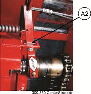
16 3. After cleaning, lube the spreader to exclude moisture from bearings and prevent condensation from forming during storage. Apply oil to roller chain drives. 4. This is a good time to inspect all adjustments and check for parts that need repair or replacement. Performing these tasks now will guarantee that the spreader is ready for use at the beginning of the next season. SHEAR PIN HUBS The spreader drive train is protected with a shear pin hub at the front end of the side drive shaft. The PTO driven apron drive is also shear bolt protected. If the shear bolts shear, determine cause of overload and correct. A4 Check beater clutch cable periodically for proper adjustment. To do this place slide clutch rod (see picture) in center of rectangular slot. Move beater clutch lever to full engaged position. Loosen cable at beater clutch lever. See Figure 10. Take out all slack in cable & re-tighten the clamp. Make sure slide clutch rod is still in center of rectangular slot. Move beater clutch lever to fully disengaged position. Check clearance between the 2 drive clutch hubs. Clearance should be 5/16. If not repeat procedure until 5/16 is obtained between the clutch hubs. Realign holes in sprocket and shear pin hub and replace bolts. Snug lock nuts only enough to remove all slack. Do Not Tighten completely. See Page 17. M1 Use 3/8x1-1/4" Grade 2 bolts and 3/8" lock nuts only. Use 1/4" Gr. 2 bolts and 1/4" lock nuts only (PTO Driven). ADJUSTMENT See Page 17. APRON CHAIN A1 The apron chain is adjusted by (2) adjuster screws located on the front of the box frame. Adjust the screws so there is no chain sag on the return side or chain is never closer than 5" to the spreader axle. When there is no more adjustment left on the adjuster screws, loosen the nuts on the screws and push the screws in as far as they will go. Then remove a link from each chain and readjust the apron chain. ROLLER CHAIN ADJUSTMENT A2 The beater drive chain is tensioned by a spring loaded tightener. A3 Side apron drive chain is automatically tensioned with a spring loaded tensioner. Proper chain tension is 1/4 to 1/2" of deflection at midspan on the loaded chain strand. Page 16 MODELS 300A & 350A


17 NOTE: Shields removed for Illustrative Purposes. Models 300 & 350 Page 17
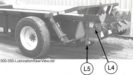
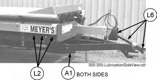
18 LUBRICATION See Page 17. Maintain oil level in two gear reducers at the check level plug, located at rear drive. When required, refill with SAE Moly Fortified gear lube or Synthetic SAE gear lube. DANGER IT IS NOT SAFE TO CLEAN OR SERVICE THE SPREADER WITH POWER OPERATING. PULLING ON THE BEATER CLUTCH ROPE DOES NOT SHUT OFF POWER TO THE SPREADER. L2 Grease two (Model 350A has 3) bearings on the side drive shaft and bearing at front end of this shaft annually. L3 There is a bearing at each end of the shaft connecting the PTO shaft with the front roller chain drive, see illustration. Grease these bearing annually. L4 Grease the bearing on the end of the beater, opposite drive side, every 10 loads. L5 Grease the bearing on the side opposite the drive on the rear apron drive shaft. Grease one place on the drive side, right behind the apron drive gearbox, every 10 loads. L6 Lubricate the PTO universal joints with 1 pump of grease every 8 hrs. Lubricate the telescoping members of the drive shaft with 4-8 pumps every 8 hrs. L8 Grease the two upper bearings on the apron drive gear reducer, four pumps every 8 hours. L9 Grease the beater clutch every 8 hours. FIGURE 10. BEATER CLUTCH LEVER & CABLE Page 18 MODELS 300A & 350A
19 This Page Intentionally Blank. Models 300 & 350 Page 19
20 REPAIR PARTS MAIN FRAME AND BOX PARTS Page 20 MODELS 300A & 350A
21 MAIN FRAME AND BOX PARTS KEY PART NO. QTY QTY DESCRIPTION 1 E Flare Upper Left - Galvanized, 14 Long E Flare Upper Left - Galvanized, 16 Long 2 E Board, Side - Poly 19-7/8 x 76-3/8 E Board, Side - Poly 19-7/8 x E Complete Floor, 59.5 x 158 E Complete Floor, 59.5 x E Hydraulic Hose Holder 5 E Angle, Front Gate - Middle 1-1/2x2" 6 E Board, Front, Poly 24 x 59-7/8 7 E Galvanized Corner (right) E Galvanized Corner (left) 8 E Belt, Front Gate 60 x 10 9 E Bar, Front Gate 3/16 x 5 x 59 3/4 10 E Frame, Main E Frame, Main 11 E Lock Assembly Complete 12 E Angle, Support - Front Gate, Upper Side Shaft Shield, Front Half Side Shaft Shield, Back Half 14 E Shield, Front Roller Chain 15 E Angle, Front Gate - Right 1-1/2x2" 16 E Flare, Upper Right-Galvanized, 14 E Flare, Upper Right-Galvanized, E Shield, PTO Drive Shaft 18 E Rubber Strap - PTO Bell 19 E Right Side Splash Pan 20 E Left Side Splash Pan 21 E Front Splash Pan 22 E Angle, Support Front Gate - Lower 23 E Flow Control Bracket - Hyd. Spreader Only 24 E Angle, Front Gate - Left 25 E Galv. Poly Floor Hold Down 26 E Poly, Floor Chain Spacer E Poly, Floor Chain Spacer 27 E SMV Spade Mounting 28 E SMV Socket Mounting 29 E Manual Holder w/ Decal 30 E Eyebolt/Rope Guide Bracket, Red Reflector 32 PM SMV Sign 33 E PTO Stand Safety Chain, Towing, lb. 35 SP Belt Hold Down, Front Gate Floor Hold Down Side Shaft Shield, Front Half Side Shaft Shield, Back Half Models 300 & 350 Page 21
22 AXLE, WHEELS, SPINDLES AND RELATED PARTS (USED ONLY ON SINGLE AXLE MODEL M300A & M350A) KEY PART NO. QTY QTY DESCRIPTION 1 E Spindle (For 20" & 22.5" Wheels) 2 E Axle, Tube Only 72-1/2" x 3-1/2 O.D. 4 E Wheel 22.5x8.25" 5 E Cap, Hub Dust 6 E Seal, Hub, CR E Nut, Spindle 8 E Pin, Cotter 9 E Washer 10 E Bearing, Outside Wheel LM E Hub w/cups & Studs 12 E Bearing, Inside Wheel JLM E Stud, Wheel 14 E Nut, Wheel Stud 15 E Inside Cups JLM E Outside Cups LM Page 22 MODELS 300A & 350A
23 AXLE, WHEELS, SPINDLES AND RELATED PARTS (USED ONLY ON TANDEM AXLE MODEL M300A & M350A) KEY PART NO. QTY QTY DESCRIPTION 1 See Page Spindle (For 20" & 22.5" Wheels) E Spindle, Special Flotation 2 E Oscilating Beam Only 3 E Oscilating Beam Retainer E Wheel 22.5x8.25" 4 E Wheel 22.5x13.5 Optional E Cx16.1 Wheel Special Flotation 5 See Page Cap, Hub Dust 6 See Page Seal, Hub, CR See Page Nut, Spindle 8 See Page Pin, Cotter 9 See Page Washer 10 See Page Bearing, Outside Wheel LM See Page Hub w/cups & Studs 12 See Page Bearing, Inside Wheel JLM See Page Stud, Wheel 14 See Page Nut, Wheel Stud 15 See Page Inside Cup JLM See Page Outside Cup LM E Guide, Poly Models 300 & 350 Page 23
24 FRONT AND SIDE DRIVE SHAFT AND RELATED PARTS Page 24 MODELS 300A & 350A
25 FRONT AND SIDE DRIVE SHAFT AND RELATED PARTS KEY PART NO. QTY QTY DESCRIPTION 1 E Key, Square - 3/8x1-3/8 Long 2 E Shaft, Side Long - For Standard Drive & Hydraulic E Shaft, Side Long - For Standard Drive & Hydraulic 3 E Key, Square - 3/8 x 1-1/2 Long 4 E Guard, Shaft /4 E Guard, Shaft /16 6 E Flange 3-Hole 62mm-3 7 E Bearing, FH206-20G-1-1/4 Greaseable 8 E /4 Flange, 3-Hole 62mm Z-Greaseable 9 E /4 FH206-20G Bearing w/flanges Complete 10 E Guard, Shaft /16 Long E Guard, Shaft /4 Long 13 REF 3 4 Collar, (not sold separately) 14 E Guard, Shaft /2 Long E Guard, Shaft /8 Long 15 E Bolt, Shear - Grade 2-3/8 x1-1/4 16A E Chain, Front Drive Roller (#60H-120 Pitches), 540 RPM Only 16B E Chain, Front Drive Roller (#60H-122 Pitches), 1000 RPM Only 18 E Bracket, Front Chain Tightener 19 E Tension Adjuster, 1/2 Bore, Rubber 20A E Sprocket, Front Drive, 60B20 x 1-1/4, 3/8 K.W., 540 RPM Only 23 E /8 Jam Nut, Shear Bolt 24 E Hub, Front Shear - 3/8 x (1-1/4 Bore) 25 E A30 Sprocket, Side Shaft Drive, 1-1/4 Bore 25A EMC A34 Sprocket, Side Shaft Drive, 1-1/4" Bore, 1000 RPM Only 27 E Shaft, Front Drive /2 Long 28 REF 1 1 Shaft, PTO Drive (see separate listing) 29 E Guard, Shaft /8 Long 30 E /4 HC20720 Bearing w/flanges Complete 31 E /4 Flange, 3-Hole 72mm Z-Greaseable 32 E Flange, 3-Hole - 72mm-3 33 E Bearing, HC /4 H.D. Greaseable 34 REF /4 H.D. Collar (not sold separately) 35 E Front Chain Tension Spring Only 36 E Eyebolt, Tension 6-1/4 37 E Shoulder Bolt, Tension Arm Models 300 & 350 Page 25
26 APRON AND BEATER DRIVE CLUTCH AND RELATED PARTS (USED WITH STANDARD CHAIN DRIVEN APRON) Page 26 MODELS 300A & 350A
27 APRON AND BEATER DRIVE CLUTCH AND RELATED PARTS (USED WITH STANDARD CHAIN DRIVEN APRON) KEY PART NO. QTY QTY DESCRIPTION 1 E Shield, Top 2 E S 1 1 Bracket, Main Gear Case 3 E Spring, Clutch Pull 4 E Slide, Clutch - Long Half 5 E Slide, Clutch - Short Half 6 E Chain, Apron Roller Drive - #60-57 links 7 E Yoke, Brass 8 E Spring, Push 9 E Washer, Flat - 1-1/2" 10 E Clutch Half, Splined 11 E Clutch Half, Keyed 12 E Sprocket, Side Shaft - 60B16 x 1-1/4" bore 13 E Tightener, Nylon Roller 14 E Shield, Gear Case Side 15 E Input Bearing Support Bracket 16 E Bearing, FHS205-16G, 1" with 2 Flanges 16A E " Flange, 3-Hole 52mm-3G Greaseable 17 E Spring, Chain Tightener 18 E Bracket, Chain Tightener 20 E Key, Square - 1/4x1-1/2" 21 E Nut, Shear Bolt - 1/4" 22 E Sprocket, Apron Drive - 60A28 x 1" 23 E Hub, Shear - Apron Drive - 1" 24 E Bolt, Shear - 1/4x1-1/2" - Grade 2 25 REF 1 1 Gear Box, Apron Drive (see separate listing) 26 E Cover, Main Gear Case 27 REF 1 1 Gear Box, Beater Drive (see separate listing) 28 E Lock Assy Complete 29 E Hinge 30 E Door Stop E E Shaft Collar, Split Models 300 & 350 Page 27
28 PTO SHAFT ASSEMBLY (USED ON ALL MODELS) KEY PART NO. QTY 300 E QTY 350 DESCRIPTION Comp. 14NW Universal Joint Telescoping Assm. w/guard E Joint and Tube Half Assm. w/guard E Yoke - 1-1/4" Bore End E NW Repair Kit E Yoke & Tube E Nylon Bearing Kit - Bearing & Snap Ring E Guard, Male (spreader half) E Joint and Shaft Half Assm. w/guard E Guard, Female (for tractor half) E Safety Decal (not pictured), E Yoke and Shaft E Spring Lock Yoke Assembly E Spring Lock Repair Kit Page 28 MODELS 300A & 350A
29 OPTIONAL APRON AND BEATER DRIVE CLUTCH AND RELATED PARTS (USED WITH OPTIONAL HYDRAULIC DRIVEN APRON) KEY PART NO. QTY 300 QTY 350 DESCRIPTION 1 E Shield, Top 2 E S 1 1 Bracket, Main Gear Case 3 E Gear Box, Beater Drive 4 E Cover, Main Gear Case 5 REF 1 1 Gear Box, Apron Drive (see separate listing) 6 REF 1 1 Motor, Hydraulic (see separate listing) 7 E Spring Clutch Pull 8 E Slide Clutch Long Half 9 E Slide Clutch Short Half 10 E Yoke, Brass 11 E Shield, Gear Case Side 12 E Shield, Motor 13 E Washer, Flat 1-1/2 14 E Spring Push 15 E Clutch Half, Splined 16 E Clutch Half, Keyed 17 E Lock Assy Complete 18 E Hinge 19 E Door Stop 20 E Shaft Collar, Split Models 300 & 350 Page 29
30 GEAR BOX COMPLETE 540 RPM BEATER DRIVE GEARBOX Used 11/13 and Later Page 30 MODELS 300A & 350A
31 GEAR BOX COMPLETE 540 RPM BEATER DRIVE GEARBOX KEY PART NO. QTY. DESCRIPTION Used 11/13 and Later Machined Housing 2 E Machined End Cap 3 E21146-W 4 Bolt 5/16-18x3/ E21144-W 2 Gear DP 4 Teeth w/ Spacer 5 E01309-W 1 Cross Shaft Output Shimming Required 03/06-10/13 6 E Snap Ring AR Spacer Kit 8 E Bearing Cup (13620) 9 E Bearing Cone (13687) 10 E Stamping Cover (69 X 9.5) X 29 Square Key Seal (1.50 X X 0.375) AR Shim Kit - Not Required On E01300-W Box Spacer Retaining Ring Shaft Input Spacer 18 E /8 NPT Pipe Plug K /8 NPT to 1/8 NPT Bushing 20 E /8 NPT Relief Plug K Gear Box Complete Models 300 & 350 Page 31
32 GEAR BOX COMPLETE 1000 RPM BEATER DRIVE GEARBOX Used 11/13 and Later Page 32 MODELS 300A & 350A
33 GEAR BOX COMPLETE 1000 RPM BEATER DRIVE GEARBOX KEY PART NO. QTY. DESCRIPTION Used 11/13 and Later 1 E Housing Machined End Cap Screw, 5/16-18 X.88, Grade Gear, 21 Teeth/M= Gear Shaft, 14 Teeth/M= E01309-W 1 Cross Shaft, Output w/ Gear Shimming Required 03/06-10/13 7 E Retaining Ring, AR Spacer Kit Not Used On Box 9 E Bearing Cup (13620) 10 E Bearing Cone (13687) 11 E Stamping Cover, X X 29 Square Key Seal (1.50 X X 0.375) Retaining Ring Spacer AR Shim Kit Spacer 18 E /8" NPT Pipe Plug K /8 NPT To 1/8 NPT Bushing 20 E /8-27 NPT Relief Plug Gear Box Complete Models 300 & 350 Page 33
34 E01300W GEARBOX COMPLETE 540 RPM BEATER DRIVE GEARBOX Used 03/06-11/13 Last Serial No. 18T13 Page 34 MODELS 300A & 350A
35 E01300W GEARBOX COMPLETE 540 RPM BEATER DRIVE GEAR BOX KEY PART NO. QTY. DESCRIPTION Used 03/06-11/13 Last Serial No. 18T13 1 E01307-W 1 Housing E End Cap A E Stamping Cover K155 4 E Bearing Cone (14137A) 5 E Bearing Cup (14276) 6 E Bearing Cone (13687) 7 E Bearing Cup (13620) 8 E21143-W 1 Gear DP 4 Teeth E21144-W 1 Gear DP 4 Teeth E01314-W 1 Shaft Input 11 E01309-W 1 Cross Shaft Output 12 E Nat. # (1.500X2.720X0.468) 13 E Nat. # (1.750X2.721X0.437) 14 E21145-W 2 Square Key (3/8X1.14) 15 E Snap Ring E21146-W 4 Bolt 5/16-18x3/4 17 E Locknut 1 5/8-18 D E21147-W 1 Locknut 1 3/8-18 UNC 19 E /8 NPT Pipe Plug K38 20 E /8 NPT Pipe Plug K34 21 E /8 NPT Relief Plug K112 E01300-W 1 Gear Box Complete Models 300 & 350 Page 35
36 GEARBOX COMPLETE 1000 RPM BEATER DRIVE GEARBOX Last Serial No Used 03/06-11/13 Page 36 MODELS 300A & 350A
37 GEARBOX COMPLETE 1000 RPM BEATER DRIVE GEARBOX Last Serial No Used 03/06-11/13 KEY PART NO. QTY. DESCRIPTION 1 E01307-W 1 Housing E End Cap A E Stamping Cover K155 4 E Bearing Cone (14137A) 5 E Bearing Cup (14276) 6 E Bearing Cone (13687) 7 E Bearing Cup (13620) 8 E21143-W 1 Gear DP 4 Teeth Shaft w/gear 10 E01309-W 1 Cross Shaft Output Seal x 2.72 x E Nat. # (1.750X2.721X0.437) 13 E21145-W 1 Square Key (3/8X1.14) 14 E Snap Ring Snap Ring Spacer Spacer 18 E21146-W 4 Bolt 5/16-18x3/4 19 E Locknut 1 5/8-18 D E /8 NPT Pipe Plug K38 22 E /8 NPT Pipe Plug K34 21 E /8 NPT Relief Plug K Gear Box Complete Models 300 & 350 Page 37
38 HYDRAULIC SYSTEM PARTS Page 38 MODELS 300A & 350A
39 HYDRAULIC SYSTEM PARTS KEY PART NO. QTY DESCRIPTION 1 E Motor Hydraulic RS (see separate listing on page 40) 2 E Hose, Flow Line 3 E Adapter, JIC to O-Ring E O-Ring Adapter 6403NWO E Valve, Motor Flow Control 6 E Tee, E O-Ring Adapter E Check Valve, LTF-8-OW 9 REF 1 Hose, Hydraulic, 8M3K-8FJX-8MP REF 1 Hose, Hydraulic, 8M3K-8FJX-8MP E Hose, Return Line 12 E Clamp, Tube 13 E Bracket, Clamp 14 E Hose Handle 15 E Hose Control Adapter 16 E Ball Valve (72-903) 17 E Control Hose 8G2-8G-8MP-8G-8MP E Bracket, Controlled Flow Valve 19 E O-Ring to JIC 90 Adapter E O-Ring Adapter E Bracket, Flow Control Valve 23 E O-Ring Adapter to JIC E O-Ring Adapter to JIC E Quick Couplers 28 E Adapter O-Ring 30 E Tee E Tee E01322 Hose/Relief Dump Line 6M3K-6FJX-8FJX E01323 Hose/Flow Control Ex to Return 8M3K-8FJX-8FJX90S E01324 Hose/In 14gpm Control to CF on Flow Control 8M3K-8FJX-8FJX E Valve Controlled Flow BGR SAE 36 E Adapter /8 Male Pipe to JIC 90 Models 300 & 350 Page 39
40 APRON DRIVE GEAR BOX STANDARD CHAIN DRIVE & OPTIONAL HYDRAULIC DRIVE APRON Page 40 MODELS 300A & 350A
41 APRON DRIVE GEAR BOX KEY PART NO. QTY. DESCRIPTION 1 I M-D Housing 2 I M-D Cover, Endcap 3 I M-D Endcap 4 I M-D Endcap (Standard) I M-D Hydraulic Adapter (Hydraulic Option) 5 I B-J Shaft, Input Worm (Standard) I B-J Shaft, Input Worm, (Hydraulic Option) 6 I260-2MPJ-D Gear, Wheel 7 I D Cover Cap (Not Shown) 8 X D Bearing, Input Cup 9 X D Bearing, Input Cone 10 X D Bearing, Output Cup/Cone 11 I D Seal, Input 12 I D Seal, Output 13 I D Gasket, Cover 14 I D Gasket, Input 15 I D0176 AR Shim, Input 16 I D0230 AR Shim, Output 17 X000-41AB-C Bolt 3/8-16 x X000-41DA-C Plug, 3/8-18 NPT 19 X E Zerk, Grease, 1/8-27 NPT 20 X000-41FG-C Bushing 3/8-18 / 1/ PR 1 Plug, 5 PSI 22 I D Retaining Ring Ext 23 I D Retaining Ring Int 24 X G Key 25 X000-48D0-A0167 AR Lube, EP 85W140 (Not Shown) 26 I D Coupler (Hydrualic Option) 27 I D Key (Hydrualic Option) 28 I D Retaining Ring (Hydrualic Option) 29 I260-9MPA-HO382 1 Complete Hydraulic Gearbox 30 I260-9MPA-HO383 1 Complete Mechanical Gearbox Models 300 & 350 Page 41
42 OPTIONAL APRON DRIVE HYDRAULIC MOTOR Page 42 MODELS 300A & 350A
43 OPTIONAL APRON DRIVE HYDRAULIC MOTOR KEY PART NO. QTY QTY DESCRIPTION Dust Seal Split Wire Ring Metal Backup Shim High Pressure Seal Metal Backup Shim Teflon Backup Shim Shaft Seal Body Seals Seal Carrier Thrust Washer Items 1-10 Included in Seal Kit: Items 1-8 Included in Seal Kit: Items 9-10 Included in Seal Kit: E Hyd. Motor RS Models 300 & 350 Page 43
44 BEATER AND RELATED PARTS OPTIONAL UPPER BEATER Page 44 MODELS 300A & 350A
45 KEY PART NO. QTY DESCRIPTION BEATERS AND RELATED PARTS OPTIONAL UPPER BEATER 1 REF 1 Gear Box, Beater Drive (see separate listing) 2 E Coupler, Coarse Splined 3 E /16x5" - GR8 Bolt - w/locking nut 4 5 E Paddle, Beater - SP14 6 E Beater Only (less paddles) 7 E Bearing Assy, GRA106RRB w/flanges And Guard 7A E Bearing Assy FH /8 w/2-72 mm - 3 Flange 8 E Bracket, Upper Beater, RH 9 E Upper Beater w/weld On Paddles 10 E Key, 3/8x3/8x1-3/8 Long 11 E Bracket Weldment, Upper Beater, LH 12 E Bracket, Beater - Left 13 E Bolts for Paddles 1/2x1-1/2" - GR5 14 E RH Beater Ears, Weld On 9 15 E LH Beater Ears, Weld On Nut, 3/8-16 Flange 17 E Angle, Tensioner Anchor 18 E Sprocket, QD-60SDS22H 19 E Roller Chain, 84 Pitches, #60H 20 E Lock Assembly, Complete 21 E Hinge 22 E Door, Upper Beater Drive 23 E Bearing 24 E Sprocket, QD-60SDS20H 25 E Key, 3/8x3/8x1-3/8 Long 26 1 Washer, 3/8 Flat 27 E HHCS 3/ E Shoulder Bolt, Tension Arm 29 E Tensioner Arm 30 E Spring 31 E Bushing 32 1 Washer, Flat 33 1 Lock Nut 34 1 Washer, Flat 35 1 Nut 36 E Rubber Rear Tension Roller 37 E Door, Lower, Used w/no Top Beater 38 E Hinge, Used w/no Top Beater 39 E Bushing, QD-SDS-1-3/8 S 40 E Bushing, QD-SDS-1-1/2 E02140 Models 300 & 350 Page 45
46 APRON AND RELATED PARTS Page 46 MODELS 300A & 350A
47 APRON AND RELATED PARTS KEY PART NO. QTY QTY DESCRIPTION E Apron, Complete - #67P " Slats 220 Links E Apron, Complete - #67P " Slats 250 Links 1 E Link, #67P11 2 E Slat, w/links - 57" Overall #67P11 3 E Washer, Flat 1-1/2" 4 E Holder, Bearing 5 E Bearing, Wood - N E Spacer 1-1/4" Long 7 E Sprocket, Apron - E67 8 E01501S 1 1 Shaft, Apron - 1-1/2" Stress Proof /4" 9 E Pin, Cotter 1/4x2-1/4" 10 E Key, Square 3/8x2-1/4" 15 See Pages 40 and REF 1 1 Gear Box, Apron Drive (see separate listing) 18 E Shield, Apron Drive Shaft 21 E Tightener Weldment, RH 22 E Roller, Nylon 23 E Pin, Cotter 24 E Washer, Machinery 25 E Nut, 3/4" NC Bolt, 3/8-16x Washer, 3/8 Flat Nut, 3/ E Tightener, Complete, RH 30 E Tightener, Complete, LH 31 E Tightener Weldment, LH Spacer, 1-1/2 Long Models 300 & 350 Page 47
48 OPTIONAL FINE SPREAD PAN AND RELATED PARTS Page 48 MODELS 300A & 350A
49 OPTIONAL FINE SPREAD PAN AND RELATED PARTS KEY PART NO. QTY QTY DESCRIPTION 1 E Shield, Right Side 2 E Pan, Fine Spread Only 3 E Mounting Plate, Left Side 4 E02039FSP 2 2 Washer, Flat - 5/8" 5 E Shield, Left Side 6 E Rod, Spread Pan 7 E Lever, Left Catch 8 E Spring 9 E Rod, Catch 10 E Catch, Left - for Pan 11 E Cable, Spread Pan E Cable, Spread Pan 12 E Bracket, Cable Pulley 13 E Clamp, Cable 14 E Belt, Spread Pan 60 Long x 6 Wide 15 E Hold-Down, Belt 16 E Mounting Plate, Right Side 17 E Catch, Right - for Pan 18 E Lever, Right Catch 19 E Pulley, Pan 20 E Spring, Pan Belt (not pictured) Models 300 & 350 Page 49
50 HYDRAULIC END GATE & RELATED PARTS QTY 300 QTY 300 QTY 350 KEY PART NO. DESCRIPTION Sgl. Axle Tan. Axle Tan. Axle 1 E Arm, Right Tube-40 E Tandem Arm, Right Tube, 300, 36 2 E Belt, Right Side 2A E Belt, Left Side 3 E Arm, Left Tube-40 E Tandem Arm, Left Tube, 300, 36 4 E Belt, Bottom End Gate 60-1/2 Long x 10 Wide 5 E Bracket, Left Hand Mounting 6 E Bracket, Right Hand Mounting 7 REF Cylinder, Hydraulic (see separate listing) 8 E Gate Hydraulic Only w/poly Boards 53" wide 9 E End Gate Insert Page 50 MODELS 300A & 350A
51 END GATE HYDRAULIC CYLINDER KEY PART NO. QTY 300 E QTY 350 DESCRIPTION Cylinder, Hydraulic w/o-ring Ports 3 x 12 & 1 3/8 Piston Rod 1 E /8 Piston Rod C 2 E Tube, Cylinder A 3 E Nut, Tie Rod Assy E Butt SF 5 E Gland 0815BBGSF 6 E Plug, Port O-Ring E Piston E Clevis Assy E Nut, Piston E Clevis Pin E Clevis Pin Retainer E Crown Seal E O-Ring E O-Ring E BU Washer E U-Cup E Wiper, Seal For 1 3/8 Rod E Packing Kit PMCK-F (Inc. Item 12-14) Models 300 & 350 Page 51
MEYER S EQUIPMENT MFG. CORP.
 INSTRUCTION AND PARTS BOOK NO. 06-1 HEAVY DUTY MANURE SPREADERS MODEL: 390 Tandem DO NOT NEVER operate this Spreader until you have read this book repair or clean this Spreader while PTO is engaged Manufactured
610 BUSHEL MANURE SPREADER
 610 BUSHEL MANURE SPREADER RODA MANUFACTURING 1008 LOCUST ST. HULL, IA. 51239 Art s-way Manufacturing 712-439-2366 Co., Inc. Hwy 9 West - PO Box 288 WWW.RODAMFG.COM Armstrong, IA. 50514 U.S.A 2 INTRODUCTION
MEYER S EQUIPMENT MFG. CORP.
 INSTRUCTION AND PARTS BOOK NO. 10-18-11 HEAVY DUTY MANURE SPREADERS MODELS: 3600 & 3750 DO NOT NEVER operate this Spreader until you have read this book repair or clean this Spreader while PTO is engaged
HEAVY DUTY MANURE SPREADERS MODEL: 3465
 INSTRUCTION AND PARTS BOOK NO. 10-18-11 HEAVY DUTY MANURE SPREADERS MODEL: 3465 DO NOT NEVER operate this Spreader until you have read this book repair or clean this Spreader while PTO is engaged Manufactured
HEAVY DUTY MANURE SPREADERS
 INSTRUCTION AND PARTS BOOK Rev. B HEAVY DUTY MANURE SPREADERS VB900 DO NOT Operate This Spreader Until You Have Completely Read This Book! NEVER Repair or Clean This Spreader While PTO is Engaged! Manufactured
25 BUSHEL MANURE SPREADER
 25 BUSHEL MANURE SPREADER RODA MANUFACTURING 338 MAIN ST. HULL, IA. 51239 Art s-way Manufacturing 712-439-2366 Co., Inc. Hwy 9 West - PO Box 288 WWW.RODAMFG.COM Armstrong, IA. 50514 U.S.A 2 INTRODUCTION
OPERATOR'S MANUAL 304 Row Mulcher
 OPERATOR'S MANUAL 0 Row Mulcher PUBLICATION DATE: // Millcreek Manufacturing Company Reservoir Road Honey Brook PA MILLCREEK PART# 0 WARNING: DO NOT assemble, operate, or maintain this equipment without
MEYER V-FORCE TWIN EXPELLER SUPER SPREADER
 OPERATOR S AND PARTS MANUAL NO. PB-74/7500 MEYER V-FORCE TWIN EXPELLER SUPER SPREADER MODEL: 7400 7500 US PATENT NO. 5,368,236 5,501,404 DO NOT OPERATE EQUIPMENT UNTIL THIS MANUAL HAS BEEN READ AND UNDERSTOOD.
250P Manure Spreader
 0P Manure Spreader Illustrated Parts Breakdown Page - Page Page Page Page Page Page Page Page Page Page Page Page Page Page - Page Page Page 0 Complete Front End PTO/Jack/Hitch Assembly Front Pulley Assembly
Operator s/parts Manual
 Operator s/parts Manual 3-Point Solid Stand Drills Pull Hitch Package Manufacturing, Inc. P.O. Box 5060 Salina, Kansas 67402-5060! Read the operator s manual entirely. When you see this symbol, the subsequent
SAFETY. Hitchpole, centre frame 1. Centre frame wheels & roller 3. Centre & wing frames 5. Wing frame wheels & roller 9.
 MANUAL Hitchpole, centre frame 1 Centre frame wheels & roller 3 Centre & wing frames Wing frame wheels & roller 9 Hydraulics 11 Clearance lights 13 Operations 1 Safety, warranty 1 SAFETY Industrial Drive,
V140 MANURE SPREADER
 V0 MANURE SPREADER ART'S WAY MANUFACTURING CO., INC. 555 W. HWY ARMSTRONG, IA 505-8-33 WWW.ARTSWAY-MFG.COM EW 00 INTRODUCTION Thank you for purchasing a Roda Spreader. We appreciate your business. Here
OPERATORS AND PARTS MANUAL NO INDUSTRIAL SERIES TWIN EXPELLER SUPER SPREADER MODEL 8500
 OPERATORS AND PARTS MANUAL NO. 03-2-8500 INDUSTRIAL SERIES TWIN EXPELLER SUPER SPREADER MODEL 8500 PATENTED U.S. PATENT NO. 5,368,236 5,50,404 DO NOT OPERATE EQUIPMENT UNTIL THIS MANUAL HAS BEEN READ AND
HOW TO ORDER PARTS: Unless this is done, we cannot provide prompt service or assure shipment of the correct parts.
 How to Order Parts HOW TO ORDER PARTS: IMPORTANT Parts must be ordered through your local authorized ASHLAND dealer. Be sure to state MODEL and SERIAL NUMBER of your machine, PART NUMBER, DESCRIPTION and
Mulching and Finishing Mowers MP and FP
 Mulching and Finishing Mowers MP and FP Parts Manual Locke Turf 0 Highway E, Opp, Alabama, () -00 Transport Wheel, Tire & Spindle MP and FP ALPHABETICAL INDEX CONTENTS PAGE 00 Hydraulic Cylinder (Rear)
OPERATOR S MANUAL REPAIR PARTS CATALOG. Models: SCP-51 & SCP-71 SCP-52 & SCP-72 SCP-91 & SCP-111 SCP-92 & SCP-112 BRILLION FARM EQUIPMENT
 OPERATOR S MANUAL REPAIR PARTS CATALOG Subsoil Chisel Plow Models: SCP-51 & SCP-71 SCP-52 & SCP-72 SCP-91 & SCP-111 SCP-92 & SCP-112 IMPORTANT! Repairs cannot be purchased retail direct from factory. Order
50 BUSHEL PTO DRIVE MANURE SPREADER
 50 BUSHEL PTO DRIVE MANURE SPREADER RODA MANUFACTURING 1008 LOCUST ST. HULL, IA. 51239 712-439-2366 WWW.RODAMFG.COM 2 INTRODUCTION Thank you for purchasing a Roda Spreader. We appreciate your business.
OPERATOR S AND PARTS MANUAL NO. PB-8100 FOR 8100 SERIES BOSS REAR UNLOAD FORAGE BOX
 OPERATOR S AND PARTS MANUAL NO. PB-8100 FOR 8100 SERIES MEYER BOSS REAR UNLOAD FORAGE BOX MODELS: 8118 8120 8122 8124 DO NOT OPERATE EQUIPMENT UNTIL THIS MANUAL HAS BEEN READ AND UNDERSTOOD. MANUFACTURED
Wheel Horse. 36 Tiller. Model No & Up. Operator s Manual
 FORM NO. 8 9 Rev. A Wheel Horse 6 Tiller for Classic Garden Tractors Model No. 7970 690000 & Up Operator s Manual IMPORTANT: Read this manual carefully. It contains information about your safety and the
RITE WAY MFG. CO. LTD. P.O.
 CO. LTD. P.O. Box 328 Imperial, Saskatchewan Canada, S0G 2J0 Ph: (306) 963-280 Fax: (306) 963-2660 Web Site: www.ritewaymfg.com E-mail: info@ritewaymfg.com Table of Contents SPECIFICATIONS... WARNING...2
V SERIES MANURE SPREADER
 V SERIES MANURE SPREADER RODA MANUFACTURING 338 MAIN ST. HULL, IA. 5239 72-439-2366 WWW.RODAMFG.COM EW 2008 2 INTRODUCTION Thank you for purchasing a Roda Spreader. We appreciate your business. Here at
PB-SXI SXI Owner / Operator s Manual & Parts Book. Starting 2017 Model Year (Including SX & SX ) 1 / 2018
 1 / 2018") PB-SXI 1 / 2018 SXI 720 865 Owner / Operator s Manual & Parts Book Starting 2017 Model Year (Including SX168865201 & SX168720202) 6990633 (1-13) Printed in U.S.A. Bobcat Company 2013 1.0 IMPORTANT INFORMATION
PB-SXI 1 / 2018 SXI 720 865 Owner / Operator s Manual & Parts Book Starting 2017 Model Year (Including SX168865201 & SX168720202) 6990633 (1-13) Printed in U.S.A. Bobcat Company 2013 1.0 IMPORTANT INFORMATION
BALE KING VORTEX 3110 BALE KING GREEN & DEGELMAN BALE KING YELLOW MODELS
 PARTS MANUAL BALE KING VORTEX 3110 BALE KING GREEN & DEGELMAN BALE KING YELLOW MODELS MANUFACTURED BY: BRIDGEVIEW MANUFACTURING INC. P.O. BOX 4 GERALD, SASK. CANADA S0A 1B0 PHONE: (306) 745-2711 FAX: (306)
GROUNDSMASTER. 52 Recycler. for 120 Traction Unit. Model No & UP. Operator s Manual
 FORM NO. 8-980 Rev A GROUNDSMASTER 5 Recycler for 0 Traction Unit Model No. 077 79000 & UP Operator s Manual IMPORTANT: Read this manual carefully. It contains information about your safety and the safety
MEYER TSS VARIABLE SPEED MODEL Front Unload Forage Boxes with Independent Outfeed Clutch
 OPERATOR S AND PARTS MANUAL NO. PB-6600 FOR 6600 SERIES MEYER TSS VARIABLE SPEED MODEL Front Unload Forage Boxes with Independent Outfeed Clutch DO NOT OPERATE EQUIPMENT UNTIL THIS MANUAL HAS BEEN READ
KING COBRA/CALIBER GRASS COLLECTION SYSTEM PARTS & OPERATORS MANUAL
 KING COBRA/CALIBER GRASS COLLECTION SYSTEM PARTS & OPERATORS MANUAL GRASS CATCHER W/WEIGHTS: TUBE KITS: BLOWER KITS: 52 542128 52 542119 5101002 60 542129 60 542120 5101003 2 WORLDLAWN POWER EQUIPMENT
RW 1200 ROCK WINDROWER. Table of Contents
 RITE WAY MFG. CO. LTD. P.O. Box 328 Imperial, Saskatchewan Canada, S0G 2J0 Ph: (306) 963-2180 Fax: (306) 963-2660 Web Site: www.ritewaymfg.com E-mail: info@ritewaymfg.com RW 1200 ROCK WINDROWER Table of
BALE KING VORTEX 3100 HD BALE KING GREEN & DEGELMAN BALE KING YELLOW MODELS
 PARTS MANUAL BALE KING VORTEX 3100 HD BALE KING GREEN & DEGELMAN BALE KING YELLOW MODELS MANUFACTURED BY: BRIDGEVIEW MANUFACTURING INC. P.O. BOX 4 GERALD, SASK. CANADA S0A 1B0 PHONE: (306) 745-2711 FAX:
BUSH HOG LAND MAINTENANCE REPAIR PARTS MANUAL MODELS: RPM & RPM SECTION: 79
 BUSH HOG LAND MAINTENANCE REPAIR S MANUAL MODELS: -0 RPM & -000 RPM SECTION: 9 0 Griffin Ave. Selma, Al. 0 () - () -00 Parts Ordering -00-0- Fax -00-- www.bushhog.com April, 0 BUSH HOG/ LAND MAINTENANCE
V- FORCE TWIN EXPELLER SUPER SPREADER MODEL:
 OPERATORS AND PARTS MANUAL NO. PB-74/7500 V- FORCE TWIN EXPELLER SUPER SPREADER MODEL: 7400 7500 US PATENT NO. 5,368,236 5,501,404 DO NOT OPERATE EQUIPMENT UNTIL THIS MANUAL HAS BEEN READ AND UNDERSTOOD.
Wheel Horse. 44 Snowthrower. for 5xi Lawn and Garden Tractors. Model No & Up. Operator s Manual
 FORM NO. 8 Rev A Wheel Horse Snowthrower for 5xi Lawn and Garden Tractors Model No. 7966 890050 & Up Operator s Manual IMPORTANT: Read this manual, and your tractor manual, carefully. They contain information
2720/12720 PARTS MANUAL 72A SECTION FLEX WING ROTARY MOWER
 0/0 This Manual applies to models 0 and 0 that use a blade pan which measures. blade hole center to blade hole center. Also blades measure 8. from hole center to blade tip. See Section if these dimensions
TO THE OWNER WARNING WARNING
 30608 (18/02/15) TO THE OWNER This manual contains information concerning the adjustment, assembly and maintenance of your Tube-Line Chainless Bale Feeder. You have purchased a dependable machine, but
LAND MAINTENANCE REPAIR PARTS MANUAL BUSH HOG MODEL: 307 SECTION: 16
 BUSH HOG LAND MAINTENANCE REPAIR S MANUAL MODEL: 0 SECTION: P.O. Box 0 Selma, AL 0-0 () - () -00 Parts Ordering -00-0- Fax -00-- www.bushhog.com BUSH HOG / LAND MAINTENANCE REPAIR S MANUAL SEPTEMBER, 0
ProLine. 44 Mower. for 120 Traction Unit. Model No & Up. Operator s Manual
 FORM NO. 9 ProLine Mower for 0 Traction Unit Model No. 05 99000 & Up Operator s Manual IMPORTANT: Read this manual carefully. It contains information about your safety and the safety of others. Also become
Post Driver Attachment
 Attachment (Shown with Optional Power Cell Rotator) Models - 600, 850 Safety Instructions This safety alert symbol indicates important safety messages in this manual. When you see this symbol, carefully
SECTION V ASSEMBLY CAUTION THE FOLLOWING SAFETY PRECAUTIONS SHOULD BE THOROUGHLY UNDERSTOOD BEFORE ATTEMPTING MACHINE ASSEMBLY.
 SECTION V ASSEMBLY CAUTION THE FOLLOWING SAFETY PRECAUTIONS SHOULD BE THOROUGHLY UNDERSTOOD BEFORE ATTEMPTING MACHINE ASSEMBLY. 1. Wear personal protective equipment such as, but not limited to protection
BUSH HOG LAND MAINTENANCE REPAIR PARTS MANUAL MODEL: 3414 SECTION: 67
 BUSH HOG LAND MAINTENANCE REPAIR S MANUAL MODEL: SECTION: 0 Griffin Ave. Selma, AL 0 () - () -00 Parts Ordering -00-0- Fax -00-- www.bushhog.com BUSH HOG/ LAND MAINTENANCE REPAIR S MANUAL July, 0 ROTARY
320 Series Models 325, 326, 327
 0 Series Models,, ROTARY MOWER Published 0/ PARTS MANUAL SECTION An Operator s Manual was shipped with the equipment. The Operator s Manual is an integral part of the safe operation of this machine and
ROTARY TILLER. Operation, Service & Parts Manual For "AS" Series. FORM: ASTillerBook.QXD
 ROTARY TILLER Operation, Service & Parts Manual For "AS" Series FORM: ASTillerBook.QXD April 2002 TABLE OF CONTENTS Preparation......................................1 Assembly Instructions.............................2
EURO REEL
 Date Purchased Machine Serial No. Options The key number system in this parts book is arranged as follows: Please order parts by number - Key numbers with two circles denotes main assemblies. - Key numbers
Table of Contents WARN INDUSTRIES PAGE A1
 INSTALLATION INSTRUCTIONS AND OPERATORS GUIDE ProVantage Bucket Conversion Kit Part Number: 84133 (50 ), 83133 (54 ) and 85133 (60 ) Application: Front Mount Plow* * Not recommended for use with Center
TT4101 Rotary Tedder
 TT Rotary Tedder 0//0 Illustrated Parts Breakdown Page Page Page Page Page Page Page Page Page Page Page Tongue Assembly S/N S/N - Tongue Assembly S/N + Main Frame S/N - Main Frame S/N to Main Frame S/N
BUSH HOG LAND MAINTENANCE REPAIR PARTS MANUAL MODEL: 405 / 406 SECTION: 17
 BUSH HOG LAND MAINTENANCE REPAIR S MANUAL MODEL: 0 / 0 SECTION: 0 Griffin Ave. Selma, AL 0 () - () -00 Parts Ordering -00-0- Fax -00-- www.bushhog.com BUSH HOG/ LAND MAINTENANCE REPAIR S MANUAL SEPTEMBER,
Worldlawn Power Equipment, Inc. Industrial Park 2415 Ashland Ave. Beatrice, NE Toll Free Number:
 Operator s Manual R WYZ48/52/60CS BAGGER Worldlawn Power Equipment, Inc. Industrial Park 2415 Ashland Ave. Beatrice, NE 68310 Toll Free Number: 1-800-267-4255 OPERATOR S MANUAL This catcher manual is for
BUSH HOG LAND MAINTENANCE REPAIR PARTS MANUAL MODEL: TD-1100 SECTION: 66
 BUSH HOG LAND MAINTENANCE REPAIR S MANUAL MODEL: TD-00 SECTION: 0 Griffin Ave. Selma, AL 0 () - () -00 Parts Ordering -00-0- Fax -00-- www.bushhog.com BUSH HOG/ LAND MAINTENANCE REPAIR S MANUAL JUNE, 00
TO THE OWNER. Model : Product Serial Number : WARNING
 28174 (09/2/11) TO THE OWNER This manual contains information concerning the adjustment, assembly and maintenance of your Tube-Line Accelerator. You have purchased a dependable machine, but only by proper
ROTARY RAKE PARTS BOOK MODEL E
 ROTARY RAKE PARTS BOOK MODEL 1150 17.00803E This parts book is furnished for your convenience only. All parts must be purchased through an authorized dealer. Call us for a dealer near you. Issue Date:
TT4100 Rotary Tedder
 TT0 Rotary Tedder Serial numbers 0 and higher Illustrated Parts Breakdown Page Page Tongue Assembly S/N - Tongue Assembly S/N to Page Page Page Page Page Tongue Assembly S/N to Tongue Assembly S/N + Main
Lime Spreader. Model SL6. Illustrated Parts Breakdown. Front Hydraulics Rear Hydraulics Manifold Components. Spinner Assembly
 Lime Spreader Model SL Illustrated Parts Breakdown Page Page Page Page Page Page Page Page Page Page 0 Front End Front Hydraulics Rear Hydraulics Manifold Components Floor & Apron Axle Assembly Apron Drive
36 Tiller Wheel Horse Lawn and Garden Tractor Attachment
 Form No. 9 6 Rev B 6 Tiller Wheel Horse Lawn and Garden Tractor Attachment Model No. 797 890000 and Up Operator s Manual English(En) Contents Page Introduction................................ Safety.....................................
4750 Drill. Repair Parts
 4750 Drill Repair Parts #615997-2016 Identification Your CrustBuster drill is identified by a Serial Number and Model Number. Record these numbers in the spaces provided in this manual and refer to them
4745 Drill OWNER'S MANUAL (06-08) #
 #") 4745 Drill OWNER'S MANUAL (06-08) # 605865 Identification Your CrustBuster drill is identified by a Serial Number and Model Number. Record these numbers in the spaces provided in this manual and refer
4745 Drill OWNER'S MANUAL (06-08) # 605865 Identification Your CrustBuster drill is identified by a Serial Number and Model Number. Record these numbers in the spaces provided in this manual and refer
FX140 & FX140R Skidding Winch Parts Manual
 EMB Manufacturing Inc. 4144 Boomer Line St. Clements, On N0B 2M0 Canada Ph: (519) 699-9283 Fax: (519) 699-4146 www.wallensteinequipment.com FX140 & FX140R Skidding Winch Parts Manual S/N 514094 & After
OPERATOR'S MANUAL & PARTS LIST
 GRAVITY GRAIN BOES OPERATOR'S MANUAL & PARTS LIST GRAVITY GRAIN BOES Model 50 (After Serial #14860 & D-Series) Model 85 (After Serial #C104749 & D-Series) Model 90 (After Serial #D0580100 & Up) Model 450
W & A 12 ROW TOP LEVELING STACKER LEVEL BANDER
 W & A 12 ROW TOP LEVELING STACKER LEVEL BANDER NO. 3640 OPERATOR S MANUAL TO THE OWNER: Congratulations on your purchase of a new W & A Top Leveling Stacker Level Bander. Your selection is an indication
OPERATOR'S MANUAL & PARTS CATALOG 12 TON RUNNING GEAR
 Unverferth Grain Handling Systems OPERATOR'S MANUAL & PARTS CATALOG 1 TON RUNNING GEAR Model RGE- Unverferth Manufacturing Co., Inc. Box 7 Kalida, OH 8 Part No. 00 PH: 1-- FAX: 1--8 www.unverferth.com
OPERATOR S AND PARTS MANUAL NO. PB-2WAY FOR 3200 & 4200 SERIES MEYER
 OPERATOR S AND PARTS MANUAL NO. PB-2WAY FOR 3200 & 4200 SERIES MEYER TSS VARIABLE SPEED MODEL Front & Rear Unload Forage Boxes with Independent Outfeed Clutch 3200 SERIES: Model 3216 Model 3218 Model 3220
Two-Stage Snow Blower For 4WD Pick Up Trucks. Operator s Manual
 Two-Stage Snow Blower For 4WD Pick Up Trucks Operator s Manual Distrubuted by: Metal Fabricating LLC P.O. Box 831 Brodheadsville, PA 18322 Phone: 570-992-9989 SnowVac.com WARRANTY POLICY Metal Fabricating
SAC Liquid Manure Flow Meter
 LM300000 REV A 11/11/2009 QUALITY PEOPLE, QUALITY PRODUCTS SAC Liquid Manure Flow Meter Operation and Service Manual ASSEMBLY CALIBRATION OPERATION REPLACEMENT PARTS READ complete manual CAREFULLY BEFORE
TT8101 Rotary Tedder
 TT0 Rotary Tedder Illustrated Parts Breakdown Page Front End Page Page Transport Axle Assembly Cylinder Linkage Page Guards Page Page Page Page Transport Lock Assembly Lift Frame Assembly Center Tunnel
VALVE AND PLUMBING KIT 2408TL LOADER AGCO & MASSEY FERGUSON TRACTORS
 ASSEMBLY MANUAL Keep With Operator s Manual VALVE AND PLUMBING KIT 2408TL LOADER AGCO & MASSEY FERGUSON TRACTORS AGCO MASSEY FERGUSON CAB ROPS ST34A 1533 X ST41A 1540 N/A X TRACTOR AND VALVE KIT GENERAL
PARTS MANUAL THIS PAGE INTENTIONALLY LEFT BLANK. Ag-Bag International, Ltd. G7000 June Appendix A
 The parts manual is organized into groups, it is designed to make the locating of parts easier. The exploded drawings also show assembly paths. All parts listed are available from your authorized Ag-Bag
DIAMONDBACK/EDGE GRASS COLLECTION SYSTEM PARTS & OPERATORS MANUAL
 DIAMONDBACK/EDGE GRASS COLLECTION SYSTEM PARTS & OPERATORS MANUAL GRASS CATCHER W/WEIGHT: TUBE KIT: BLOWER KIT: 48 5101305 632093 632078 52 5101305 542119 632074 60 632086 542120 632081 3 WORLDLAWN POWER
Premium Supply. Direct Push. Models PCK-3530-DP PCK DP PCK-530-DP. Operator s Manual and Installation Instructions
 Direct Push Models PCK-3530-DP PCK-3530-2DP PCK-530-DP Operator s Manual and Installation Instructions Premium Supply 2038 West Interstate 30 866-934-0777 Proud members of: and June 20, 2018 Table of Contents
VALVE AND PLUMBING KIT INSTRUCTIONS SMC 84Q & 2408 LOADERS NEW HOLLAND TRACTORS MODEL 2WD 4WD LESS CAB WITH CAB 1720 X X X 1920 X X X
 ASSEMBLY MANUAL Keep With Operator s Manual VALVE AND PLUMBING KIT INSTRUCTIONS SMC 84Q & 2408 LOADERS NEW HOLLAND TRACTORS MODEL 2WD 4WD LESS CAB WITH CAB 1720 X X X 1920 X X X TRACTOR AND VALVE KIT GENERAL
BH200 SERIES ROTARY CUTTER
 Revised Published01/19 BH200 SERIES ROTARY CUTTER PARTS MANUAL SECTION 121 MODELS BH215, BH216, BH217 An Operator s Manual was shipped with the equipment. The Operator s Manual is an integral part of the
TABLE OF CONTENTS DESCRIPTION. Safety Instructions & Safety Sign Locations Operating Instructions Assembly Instructions...
 TABLE OF CONTENTS DESCRIPTION PAGE Warranty... 1 Safety Instructions & Safety Sign Locations... 2 Operating Instructions... 3 Assembly Instructions... 5 500 & 600 Snowblower Drawings... 8 500 & 600 Snowblower
TWIN ROTARY RAKE PARTS BOOK MODEL
 TWIN ROTARY RAKE PARTS BOOK MODEL 2650 17.01135 This parts book is furnished for your convenience only. All parts must be purchased through an authorized dealer. Call us for a dealer near you. Issue Date:
Lime Spreader. Model SL6. Illustrated Parts Breakdown. Front Hydraulics Rear Hydraulics Manifold Components. Spinner Assembly
 Lime Spreader Model SL Illustrated Parts Breakdown Page Page Page Page Page Page Page Page Page Page 0 Front End Front Hydraulics Rear Hydraulics Manifold Components Floor & Apron Axle Assembly Apron Drive
Model 858-RH. Operating and Assembly Manual. Palmor Products Inc Serum Plant Road Thorntown, IN 46071
 Model 5-RH Operating and Assembly Manual Palmor Products Inc. 55 Serum Plant Road Thorntown, IN 6071 3/31/015 SAFETY RULES Remember, any power equipment can cause injury if operated improperly or if the
Rotary Brush Cutter. Model Number RBV. Serial Number. Serial Number and Greater. Maximum Flow Rate gpm. Phone: RBV
 Rotary Brush Cutter Model Number RBV. Serial Number. Serial Number 75 and Greater Maximum Flow Rate gpm. Phone: 0--700 0/5/0 Revised // RBV Features of Virnig Mfg. Inc. Rotary Brush Cutter include: diameter
STOP. Broadcast Spreader. Operator's Manual. Model No Safety Assembly Operation Maintenance Parts
 Operator's Manual STOP Broadcast Spreader Model No. 486.2400 DO NOT RETURN TO STORE For Missing Parts or Assembly Questions Call 1-866-56-8388 CAUTION: Before using this product, read this manual and follow
Drive Over- Pit. Belt Accelerator & Multi-Purpose Belt Loader OWNER'S MANUAL (08/08)
") Drive Over- Pit Belt Accelerator & Multi-Purpose Belt Loader OWNER'S MANUAL 00028100 (08/08) Belt Accelerator & Multi-Purpose Belt Loader Table of Contents Warranty Information................. Inside
Drive Over- Pit Belt Accelerator & Multi-Purpose Belt Loader OWNER'S MANUAL 00028100 (08/08) Belt Accelerator & Multi-Purpose Belt Loader Table of Contents Warranty Information................. Inside
OPERATOR & PARTS MANUAL
 OPERATOR & PARTS MANUAL 142644 v1.2 DEGELMAN INDUSTRIES LTD. BOX 830-272 INDUSTRIAL DRIVE, REGINA, SK, CANADA, S4P 3B1 FAX 306.543.2140 PH 306.543.4447 1.800.667.3545 DEGELMAN.COM MANURE SPREADER M28 &
Case STX/NH TJ
 Case STX/NH TJ 0-0 Tractors MANUAL Case STX/NH TJ 0-0 Tractors Blades, pivot frames Tractor fit-up Dlock, mounting Hydraulics Operation, maintenance Safety, warranty Industrial Drive, Box 0 Regina, Sask.
Twin Screw Undercar Conveyor
 Twin Screw Undercar Conveyor Owner s Manual #19015700 05-00 Table of Contents Operator Qualifications...................................... 1 Safety.................................................. 2-4
Rotary Brush Cutter (Standard Flow)
") Rotary Brush Cutter (Standard Flow) Model Number RBV. Serial Number. Serial Number 6795-0050 Maximum Flow Rate gpm. For and 5 GPM Max Models Phone: 0-9-700 0/5/0 Revised // RBV Features of Virnig Mfg.
Rotary Brush Cutter (Standard Flow) Model Number RBV. Serial Number. Serial Number 6795-0050 Maximum Flow Rate gpm. For and 5 GPM Max Models Phone: 0-9-700 0/5/0 Revised // RBV Features of Virnig Mfg.
Walker Loader Bucket OPERATOR S AND PARTS MANUAL
 Walker Loader Bucket OPERATOR S AND PARTS MANUAL Please Read and Save These Instructions For Safety, Read all Safety and Operation Instructions Prior To Operating Machine P/N 6690 TABLE OF CONTENTS Introduction
UTS 696 Under Tailgate Spreader Owner s Manual
 July 15, 2004 Lit. No. 94838 UTS 696 Under Tailgate Spreader Owner s Manual Read this manual before installing or operating the spreader. This manual is for UTS 696 Under Tailgate Spreaders with serial
WARRANTY REGISTRATION AND POLICY
 WARRANTY REGISTRATION AND POLICY Buhler Manufacturing products are warranted for a period of twelve (12) months from original date of purchase, by original purchaser, to be free from defects in material
OWNERS MANUAL. Model No LB. PUSH BROADCAST SPREADER. Assembly Operation Maintenance Repair Parts
 OWNERS MANUAL Model No. 45-02102-101 SHIELD UP - 8 TO 18 FT. SPREAD WIDTH SHIELD DOWN - 3 TO 4 FT. SPREAD WIDTH 125 LB. PUSH BROADCAST SPREADER CAUTION: Read Rules for Safe Operation and Instructions Carefully
tRIPr Chief Grain Cart. Operator s Manual. Operator s Manual
 125-000-01 125-000-01 1tRIPr 1tRIPr Operator s Manual 1210 Chief Grain Cart Operator s Manual Operator s Manual TO THE DEALER Predelivery/Delivery Checklist 1210 Grain Cart PREDELIVERY/DELIVERY CHECKLIST
BUSH HOG LAND MAINTENANCE REPAIR PARTS MANUAL MODEL: 280 SERIES SECTION: 59
 BUSH HOG LAND MAINTENANCE REPAIR S MANUAL MODEL: 0 SERIES SECTION: P.O. Box 0 Selma, AL 0-0 () - () -00 Parts Ordering -00-0- Fax -00-- www.bushhog.com BUSH HOG/ LAND MAINTENANCE REPAIR S MANUAL JUNE,
GRASS CATCHER PART S & OPERATORS MANUAL
 GRASS CATCHER PART S & OPERATORS MANUAL WORLDLAWN POWER EQUIPMENT, INC. WORLDLAWN.COM 2415 ASHLAND AVE BEATRICE, NE 68310 800-267-4255 FAX 402-223-4103 2 3 4 OPERATORS MANUAL This catcher manual is for
DRILL 2300 SAFETY SECTION
 DRILL 2300 SAFETY SECTION RECOGNIZE SAFETY ALERT SYMBOL WARNING: KEEP RIDERS OFF UNIT Riding on any agricultural equipment is very dangerous. People can be killed or seriously injured when accidentally
BEFCO. Operator s Manual BABY HOP & HOP FERTILIZER SPREADERS ACCESSORIES SIDE ROW DISCHARGE. AA4-120 (fits models Hop 209 & 212) DEFLECTOR
 DEFLECTOR") BEFCO Operator s Manual BABY HOP & HOP FERTILIZER SPREADERS ACCESSORIES SIDE ROW DISCHARGE AA-0 (fits models Hop 09 & ) DEFLECTOR AA-0 (fits models Baby Hop 0 & 06) 009-95 (fits models Hop 0 & 06) 009-968
BEFCO Operator s Manual BABY HOP & HOP FERTILIZER SPREADERS ACCESSORIES SIDE ROW DISCHARGE AA-0 (fits models Hop 09 & ) DEFLECTOR AA-0 (fits models Baby Hop 0 & 06) 009-95 (fits models Hop 0 & 06) 009-968
Litter Spreader. Models SP400, SP450, SP500, SP550. Illustrated Parts Breakdown
 Litter Spreader Models SP00, SP0, SP00, SP0 Illustrated Parts Breakdown Page Front End Page Hydraulic System (w/ Side Mounted Reservoir) Page Hydraulic System (w/ Front Mounted Reservoir) Page Hydraulic
ASSEMBLY MANUAL. Keep With Operator s Manual
 ASSEMBLY MANUAL Keep With Operator s Manual 2-6347 VALVE AND PLUMBING KIT INSTRUCTIONS SMC 64Q LOADER KUBOTA TRACTORS MODEL 2WD 4WD LESS CAB WITH CAB B2150DT & B2150HSD X X B8200DT & B8200HSD X X B9200DT
MANURE SPREADER MS1117. HSMFG0903 Rev.1 HPOMSP3
 OPERATOR S MANUAL MANURE SPREADER MS1117 HSMFG0903 Rev.1 HPOMSP3 TABLE OF CONTENTS TABLE OF CONTENTS...INSIDE COVER WARRANTY & NOTES...1 DEALER PRE-DELIVERY & DELIVERY CHECKLIST...3 SPECIFICATIONS...5
CRUSTBUSTER OWNER / OPERATOR MANUAL
 CRUSTBUSTER OWNER / OPERATOR MANUAL MODEL # CB-1 CRUSTBUSTER Manufactured by: LEWIS BROTHERS MANUFACTURING, INC. Post Office Box 146 Baxley, GA 31513 Tel: (912) 367-4651 Fax: (912) 367-3958 5-2-17 1 INTRODUCTION
A1062 & A1072 AUGER ASSEMBLY MANUAL. Read & understand all instructions pertaining to this auger prior to use!
 A1062 & A1072 AUGER ASSEMBLY MANUAL Read & understand all instructions pertaining to this auger prior to use! Safety Alert Watch for this ALERT Symbol. It identifies potential hazards to Personal SAFETY
EUROPEAN REAR ENGINE RIDER SERIES 20
 Parts Manual for EUROPEAN REAR ENGINE RIDER SERIES 20 MODEL E281320BE E331520KVE McDonough, GA, 30253 U.S.A. Briggs & Startton Yard Power Products Group Copyright 2006 Briggs & Startton Corporation Milwaukee,
FERTILIZER AND LIME TRAILER SPREADERS MODELS: 507, 508, AND 509
 FERTILIZER AND LIME TRAILER SPREADERS MODELS: 507, 508, AND 509 OWNERS MANUAL General Fertilizer Equipment INC. 1-800-277-4377 SPEEDYSPREAD.COM FAX # 336-854-5796 JUNE 2003 IMPORTANT CONTACT INFORMATION
4050A. Tire Changer. Parts Identification. For servicing single piece automotive and most light truck tire/wheel assemblies
 4050A Tire Changer For servicing single piece automotive and most light truck tire/wheel assemblies Parts Identification READ these instructions before placing unit in service KEEP these and other materials
Manure Spreader. Model 25G. Operator s Manual THIS MANUAL MUST BE READ AND UNDERSTOOD BEFORE ANYONE OPERATES THIS MACHINE!
 Manure Spreader Model 25G Operator s Manual THIS MANUAL MUST BE READ AND UNDERSTOOD BEFORE ANYONE OPERATES THIS MACHINE! Manual# 990012 Revised 05/2008 YOU MUST FILL OUT YOUR WARRANTY REGISTRATION TO ACTIVATE
Model 802 Center Mount Adapter For New Holland 9030 & TV140 Bi-Directional Tractors PARTS CATALOG
 Model 802 Center Mount Adapter For New Holland 9030 & TV140 Bi-Directional Tractors 1 PARTS CATALOG TABLE OF CONTENTS Frame & Tractor Linkage...2,3 Header Linkage & Float Group...4,5 Header Drive Hydraulics
FLAIL MOWER SHREDDER
 FLAIL MOWER SHREDDER Operation, Service, & Parts Manual For Models: GML41, 49, 61, 69, & 79 February 2006 FORM: GMLMower.QXD TABLE OF CONTENTS Installation....................................................1
BUSH HOG LAND MAINTENANCE REPAIR PARTS MANUAL MODEL: 280 SERIES SECTION: 59
 BUSH HOG LAND MAINTENANCE REPAIR S MANUAL MODEL: 0 SERIES SECTION: 0 Griffin Ave. Selma, AL 0 () () 00 Parts Ordering 00 0 Fax 00 www.bushhog.com BUSH HOG/ LAND MAINTENANCE REPAIR S MANUAL October, 0 0
3509 & 3511 BACKHOE 3-POINT HITCH / CATEGORY II PARTS MANUAL. Part Number: MODEL NUMBER: Rev. 4
 509 & 5 BACKHOE -POINT HITCH / CATEGORY II PARTS MANUAL SERIAL NUMBER: Manual Number: PM609 Part Number: 5509 MODEL NUMBER: Rev. 800-56-00 I www.paladinlcg.com 50 Gay Street, Delhi, IA 5, United States