GPSMAP 2206/2210 & GPS 17
|
|
|
- Christal Barker
- 6 years ago
- Views:
Transcription


1 GPSMAP 2206/2210 & GPS 17 installation instructions Graphic to be replaced
2 Copyright 2006 Garmin Ltd. or its subsidiaries Garmin International, Inc East 151 st Street, Olathe, Kansas 66062, U.S.A. Tel. 913/ or 800/ Fax 913/ Garmin (Europe) Ltd. Unit 5, The Quadrangle, Abbey Park Industrial Estate, Romsey, SO51 9DL, U.K. Tel. 44/ Fax 44/ Garmin Corporation No. 68, Jangshu 2 nd Road, Shijr, Taipei County, Taiwan Tel. 886/ Fax 886/ All rights reserved. Except as expressly provided herein, no part of this manual may be reproduced, copied, transmitted, disseminated, downloaded, or stored in any storage medium, for any purpose without the express prior written consent of Garmin. Garmin hereby grants permission to download a single copy of this manual onto a hard drive or other electronic storage medium to be viewed and to print one copy of this manual or of any revision hereto, provided that such electronic or printed copy of this manual must contain the complete text of this copyright notice and provided further that any unauthorized commercial distribution of this manual or any revision hereto is strictly prohibited. Information in this document is subject to change without notice. Garmin reserves the right to change or improve its products and to make changes in the content without obligation to notify any person or organization of such changes or improvements. Visit the Garmin Web site ( for current updates and supplemental information concerning the use and operation of this and other Garmin products. Garmin, GPS, CANet, and Ultrascroll are registered trademarks or trademarks of Garmin Ltd. or its subsidiaries and may not be used without the express permission of Garmin. Safety Information WARNING: This product, its packaging, and its components contain chemicals known to the State of California to cause cancer, birth defects, or reproductive harm. This Notice is being provided in accordance with California s Proposition 65. If you have any questions or would like additional information, please refer to our Web site at Limited Warranty This Garmin product is warranted to be free from defects in materials or workmanship for one year from the date of purchase. Within this period, Garmin will at its sole option repair or replace any components that fail in normal use. Such repairs or replacement will be made at no charge to the customer for parts or labor, provided that the customer shall be responsible for any transportation cost. This warranty does not cover failures due to installation errors, abuse, misuse, accident, or unauthorized alteration or repairs. THE WARRANTIES AND REMEDIES CONTAINED HEREIN ARE EXCLUSIVE AND IN LIEU OF ALL OTHER WARRANTIES EXPRESS OR IMPLIED OR STATUTORY, INCLUDING ANY LIABILITY ARISING UNDER ANY WARRANTY OF MERCHANTABILITY OR FITNESS FOR A PARTICULAR PURPOSE, STATUTORY OR OTHERWISE. THIS WARRANTY GIVES YOU SPECIFIC LEGAL RIGHTS, WHICH MAY VARY FROM STATE TO STATE. IN NO EVENT SHALL GARMIN BE LIABLE FOR ANY INCIDENTAL, SPECIAL, INDIRECT OR CONSEQUENTIAL DAMAGES, WHETHER RESULTING FROM THE USE, MISUSE, OR INABILITY TO USE THIS PRODUCT OR FROM DEFECTS IN THE PRODUCT. Some states do not allow the exclusion of incidental or consequential damages, so the above limitations may not apply to you. Garmin retains the exclusive right to repair or replace the product or offer a full refund of the purchase price at its sole discretion. SUCH REMEDY SHALL BE YOUR SOLE AND EXCLUSIVE REMEDY FOR ANY BREACH OF WARRANTY. Online Auction Purchases: Products sold through online auctions are not eligible for rebates or other special offers from Garmin. Online auction confirmations are not accepted for warranty verification. To obtain warranty service, an original or copy of the sales receipt from the original retailer is required. Garmin will not replace missing components from any package purchased through an online auction. International Purchases: A separate warranty is provided by international distributors for units purchased outside the United States. This warranty is provided by the local in-country distributor and this distributor provides local service for your unit. Distributor warranties are only valid in the area of intended distribution. Units purchased in the United States or Canada must be returned to the Garmin service center in the United Kingdom, the United States, Canada, or Taiwan for service. To obtain warranty service, contact your local Garmin authorized dealer or call Garmin Product Support for shipping instructions and an RMA tracking number. The product should be securely packed with the tracking number clearly written on the outside of the package. The product should then be sent, freight charges prepaid, to any Garmin warranty service station. A copy of the original sales receipt is required as the proof of purchase for warranty repairs. April 2006 Part Number Rev. A Printed in Taiwan

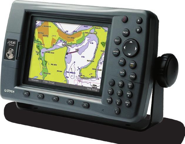
3 INTRODUCTION The GPSMAP 2206/2210 Multi-Function Display (MFD) and GPS 17 must be properly installed according to the following instructions for the best possible performance. To complete the installation, you need the appropriate fasteners, tools, and mounts listed in each section. These items are available at most marine dealers. Always wear safety goggles, ear protection, and a dust mask when drilling, cutting, or sanding. When drilling or cutting, always check first to see what is on the opposite side of the surface. Mount the GPSMAP 2206/2210 in a location that provides a clear, glare-free view of the display and easy operation of the controls. If you experience difficulty installing the unit, contact Garmin Product Support or seek the assistance of a professional installer. Mounting knob Bail mount Mounting holes GPSMAP
 INSTALLATION INSTRUCTIONS NOTE: Mounting hardware")


4 Surface Mounting the GPSMAP 2206/2210 Tools Drill and drill bit Screwdriver Pencil Mounting hardware (not included) INSTALLATION INSTRUCTIONS NOTE: Mounting hardware (fasteners) not included. Mounting holes are 5/16" (7.9 mm) in diameter. To install the bail mount and unit: 1. Using the bail mount as a template, mark the location of the four mounting holes. Be sure to leave at least two inches of clearance behind the unit for the wiring. 2. Using an appropriate size drill bit, drill pilot holes for the fasteners. 3. Secure the bail mount to the surface with the fasteners. 4. Loosen the mounting knobs. 5. Slide the unit into the bail mount, and tighten the mounting knobs. Bail Mount Mounting knobs Bail mount 2


5 Flush Mounting the GPSMAP 2206/2210 Tools Flush Mount Template Jig saw Masking tape Scissors Drill Drill bits 1/8" (3 mm) and 3/8" (6 mm) 1/16" (2 mm) Allen (Hex) wrench Sockets or wrenches Hammer Center punch To flush mount the GPSMAP 2206/2210: Flush Mount 1. Trim the Flush Mount Template, and tape it in the location you want. 2. Using the center punch, indent the center of each mounting hole location. 3. Using an 1/8" (3 mm) drill bit, drill the four mounting holes. 4. Using a 3/8" (6 mm) drill bit, drill a hole to begin cutting the mounting surface. 5. Using the jig saw, cut the mounting surface along the inside of the dashed line indicated on the template. Use a file and sandpaper to refine the size of the hole. Be very careful when cutting this hole. There is only a small amount of clearance between the case molding and the mounting holes. 6. Install the four mounting studs into unit by screwing the shorter, threaded section into the back of the unit. Use a 1/16" (2 mm) Allen wrench to tighten the mounting studs until the stop contacts the case. Be careful not to overtighten because this may damage the mounting stud! The studs have a reusable thread-locking patch pre-applied from the factory. 7. Place the unit into the cut-out of the mounting surface. 8. Place washers over the mounting studs, then thread on one hex nut per mounting stud. Tighten all four until the unit is snug against the mounting surface. Install and tighten the second hex nut set on all four mounting studs to lock the first set in place. 230mm 208mm Flush Mount Template Stud Washer Hex nuts Mounting surface 3

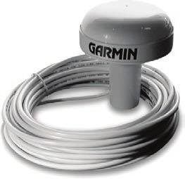
6 Installing the GPS 17 You can install flush mount or install the GPS 17 on any standard 1" O.D. (Outer Dimension), 14 threads-per-inch marine mount. When mounting the GPS 17, the cable can be run externally, through the mounting panel, or through the center of the marine mount. The GPS 17 connects to the 18-pin Power/Data Cable on the GPSMAP 2206/2210 and provides the GPS/WAAS signal for the unit. If two or more GPSMAP 2206/2210 units are installed, only one GPS 17 needs to be installed. To ensure the best reception, mount the GPS 17 in a location that has a clear, unobstructed view of the sky in all directions. Avoid mounting the GPS 17 where it is shaded by the boat s superstructure, a radome antenna, or mast. Sailboat users should avoid mounting the unit high on the mast to prevent inaccurate speed readings caused by excessive heeling. The unit provides more stable readings if it is located nearer to water level. Mount the GPS 17 at least 3 ft away from (preferably above) the path of any radar beam or a VHF radio antenna. Temporarily secure the unit in the preferred mounting location and test for correct operation. With correct operation verified, permanently mount the unit. If interference with other electronics is experienced, try a different location. NOTE: Never paint the GPS 17 or clean it with harsh solvents. Radar BELOW - OK EMI ABOVE - BEST Radar BETTER 3' VHF Radio Antenna NOTE: Mount the antenna at least 3 ft away from (preferably above) the path of any radar beam or a VHF radio antenna. EMI (Electromagnetic Interference) from engine components Signal Interference BEST GOOD SS JAYHAWK To flush mount the GPS 17: 1. Cut out the Flush Mount Drilling Template provided on page 13, and tape it on the selected mounting location. 2. Mark the center of each mounting hole by tapping the end of a center punch or pointed object with a hammer. If the cable is going to be installed through the mounting panel, mark the center of the additional hole. 3. Drill the holes using the appropriate drill bits. 4. Align the GPS 17 over the mounting holes and fasten it using M4 screws. The mounting threads in the GPS 17 are 8.10 mm deep. Do not use screws that thread into the GPS 17 deeper than 8 mm, or the case may be damaged. The GPS 17 can be installed with the coax through the panel or on the outside of the unit. If the coax is run through the panel, seal the outside exit area with marine sealant. Mounting holes Bottom of GPS 17 4


7 To attach the enclosed pole mount to the GPS 17: 1. Thread the cable though the pole mount. 2. Align the tab on the mount to the notch on the GPS Use the enclosed screws to secure the mount to the base. To mount the GPS 17 with the cable run outside the mount: 1. Place the cable in the vertical slot along the side of the base of the unit. 2. Screw the GPS 17 onto the mount. DO NOT overtighten the head. It is possible to over tighten the unit and cut the cable. 3. With the GPS 17 and mount installed, fill the remaining gap in the cable exit with a marine sealant. 4. Route the cable away from sources of electronic interference. To mount the GPS 17 with the cable run through the mount: 1. Position the mount in the preferred location and mark the approximate center of the mount. 2. Drill a hole large enough for the cable to pass through. 3. Slide the cable through the mount, and then screw the GPS 17 onto the mount. 4. Fasten the mount to the boat. 5. Route the cable away from sources of electronic interference. Attaching the Pole Mount to the GPS 17 Cable run externally Align Notch Cable run internally Attaching the GPS 17 to a Pole Mount 5
. Wiring instructions are found on the following pages.")

 paddle drill bit or hole saw, drill the installation hole. 3.")
8 Wiring and Cables The GPSMAP 2206/2210 comes with an 18-pin Power/Data cable. For some installations, it may be necessary to drill 1.25" (31.7 mm) holes to route the connector end of the cables. Garmin rubber grommets are provided to cover the installation holes (see below). Wiring instructions are found on the following pages. If you experience difficulty installing the unit, contact an installation professional. The grommets may not be needed in some installations. The grommets do NOT create a waterproof seal. Apply a marine sealant after installation to weatherproof around the grommet and cable. Additional grommets can be purchased from your Garmin dealer or direct from Garmin. Be sure to test the system before installing the grommets. Tools Drill 1.25" (31.7 mm) paddle drill bit or hole saw Pencil Utility knife Marine sealant (optional) To install the cable grommet: 1. Mark the location where the Power/Data cable is to route through. 2. Using a 1.25" (31.7 mm) paddle drill bit or hole saw, drill the installation hole. 3. Refer to the diagram below for trimming instructions. Carefully trim the cable hole, as needed. 4. Route the cable to the unit. 5. Spread the grommet apart at the split, and place it around the cable (see below). 6. Firmly push the grommet into the installation hole until it is seated. Apply marine sealant, as needed, to weatherproof the cable. Use this hole (no trim) for the Power/Data, or GPS 17 cable Split 6
9 CANet Wiring for the GPSMAP 2206/2210 CANet is a high-speed sonar network. Using the CANet interface optimizes the performance of the CANet-compatible units. CANet compatible unit device features, such as Ultrascroll, are affected if a serial interface is used. To install the 3-Wire Connector: 1. Insert up to three wires into the 3-wire connector. Do not strip the wire insulation. Refer to the following CANet Terminator Connection diagram. 2. Use a standard pair of pliers to fully depress the red button into the connector. 3. Wipe the excess water repellent gel from the connector. The following diagram shows CANet wiring for the GPSMAP 2206/2210. CANet TERMINATOR CANet TERMINATOR GREEN WHITE BLACK RED ORANGE BLACK RED GREEN WHITE BLACK DRAIN* ORANGE 3A FUSE CANet EXTENSION CABLE GREEN WHITE ORANGE BLACK DRAIN* FUSE** GREEN WHITE ORANGE BLACK RED CANet COMPATIBLE DEVICE BATTERY VDC 1 CANet Wiring Diagram Notes: * Connect the drain wire only on one side. ** Fuse size varies based on the unit. See the unit s owner s manual for specific fuse information. 7
10 Power/Data Cable Wiring The following pages contain several wiring diagrams. The first diagram on the next page is a simple diagram showing the GPSMAP 2206/2210 MFD using the 18-pin Power/Data wiring harness and the GPS 17. If two GPSMAP 2206/2210 units are installed and connected, only one GPS 17 antenna needs to be installed. Next are wiring diagram examples showing the GPSMAP 2206/2210 using the 18-pin Power/Data wiring harness interfacing with a variety of different equipment. Refer to the wiring diagram that best suits your needs. For third-party devices, refer to the wiring guidelines included with that equipment. Use 22 AWG (18 AWG for the Red and Black wires), shielded, twisted-pair wiring for extended runs of wire. Solder all connections and seal the connection with heat shrink tubing. If networking two MFDs, the GPS 17 and NMEA input devices should only be attached to one MFD. A pinout of the cable is shown below. Power/Data Cable Input/Output Ports The GPSMAP 2206/2210 Power/Data cable has four I/O (Input/Output) ports. Ports 1 and 2 communicate with other NMEA-compliant devices, such as VHF radios, NMEA instruments, autopilots, or PCs (Port 1 only). You can input one NMEA device to each port, and output in parallel to three NMEA devices per port. Port 3 is reserved for use with Garmin sounder modules. Port 4 is reserved for use with the Garmin GPS 17 GPS/WAAS antenna. The following formats are supported for connection of external devices: Garmin proprietary sonar module and NMEA 0183 version The following are the sentences for NMEA 0183, version 3.01 and later output: Approved sentences GPBWC, GPRMC, GPGGA, GPGSA, GPGSV, GPGLL, GPBOD, GPRMB, GPRTE, GPVTG, GPWPL, and GPXTE. Garmin proprietary sentences PGRME, PGRMM, PGRMZ, and PSLIB. The unit also includes NMEA input with support for the WPL sentence, DSC, and sonar NMEA input with support for the DPT (Depth) or DBT, MTW (Water Temp), and VHW (Water, Speed, and Heading) sentences. The unit interface must be set to NMEA In/NMEA Out Documentation concerning NMEA and RTCM formats and sentences are available for purchase from: National Marine Electronics Association (NMEA) Seven Riggs Avenue Severna Park, MD U.S.A Cable End View PIN # COLOR FUNCTION 1 N/C 2 N/C 3 N/C 4 WHITE/BROWN PORT 3 DATA IN 5 WHITE/BLUE PORT 3 DATA OUT 6 ORANGE ACCESSORY ON 7 N/C 8 N/C 9 VIOLET PORT 2 DATA IN 10 GRAY PORT 2 DATA OUT 11 YELLOW ALARM LOW 12 N/C 13 WHITE PORT 4 DATA IN 14 GREEN PORT 4 DATA OUT 15 RED DC POWER INPUT 16 BROWN PORT 1 DATA IN 17 BLUE PORT 1 DATA OUT 18 BLACK GROUND (POWER/DATA) 8
11 FUSE 3 A WIRE COLOR RED BLACK + - BATTERY VOLTS DC WIRE COLOR RED (POWER) BLACK (GROUND) FUSE 1 A GPS 17 GPS/WAAS SENSOR ORANGE YELLOW (ON) GREEN BLUE (DATA IN) WHITE WHITE (DATA OUT) GPSMAP 2206/2210 and GPS 17 Basic Wiring + - GPSMAP 2206/2210 and NMEA Device with Sonar Output or VHF Radio with DSC + - GPSMAP 2206/2210 and NMEA Device/AUTOPILOT GPSMAP 2206/2210 with a Computer Serial Port 9
12 GPS 17 Optional Alarm Wiring The GPSMAP 2206/2210 has an alarm circuit that can be used with a lamp, a horn, or both to alert you when the unit displays a message. The alarm circuit pulls low when the alarm sounds. The alarm does not have to be wired for the unit to function. The maximum current is 100 milliamps. A switch or relay can be used to select between visual and audible alerts ma Max Coil Current 10

13 Final Wiring Connection After all the wiring is complete, plug the 18-pin harness into the center connector on the backside of the GPSMAP 2206/2210. The 5-pin port on the right side is intended for future interfacing features and does not require connection at this time. With power applied to the circuit, test the installation by pressing the POWER key on the front of the unit. See the GPSMAP 2206/2210 Owner's Manual for steps on initializing the receiver. 18-pin connector 5-pin CANet connector 11
14 12
15 Flush Mount Drilling Template Drill using a 11/64" (4.5 mm) drill bit Drill this 3/4" (19 mm) hole if the coax is going to be installed through the mounting panel 13
16 Copyright 2006 Garmin Ltd. or its subsidiaries Garmin International, Inc East 151 st Street, Olathe, Kansas 66062, U.S.A. Garmin (Europe) Ltd. Unit 5, The Quadrangle, Abbey Park Industrial Estate, Romsey, SO51 9DL, U.K. Garmin Corporation No. 68, Jangshu 2 nd Road, Shijr, Taipei County, Taiwan Part Number Rev. A
ECHOMAP PLUS 60/70/90 SERIES Installation Instructions
 ECHOMAP PLUS 60/70/90 SERIES Installation Instructions Important Safety Information WARNING See the Important Safety and Product Information guide in the product box for product warnings and other important
Solid-State Compass with GPS Receiver
 Owner s Guide & Installation Instructions Solid-State Compass with GPS Receiver Model GH2183 Record the serial number found on the sensor. Serial No. Date of Purchase 17-489-01 rev. 01 04/22/08 1 WARNING
Installation Instructions
 Installation Instructions AMP RESEARCH Power Step by Bestop Automatic Retracting Running Board Vehicle Application Nissan Titan King Cab 2004 and newer (5 ft.) Part Number: 75106-01 Nissan Titan Crew Cab
Part Number Rev. B. Unit housing Hex nuts. Unit Rubber seal Hex bolts. Hex bolts. Hex nuts. Figure 1
 Installing the Flush Mount Kit Use this kit to flush mount a GPSMAP 500 series unit into a flat panel. Select an appropriately sized location for the unit. Use the Flush Mount Template provided to determine
Crestron TTK-MP/MPC/IPAC & SMK-MP/MPC/IPAC TableTop and Swivel Mount Kits Installation Guide
 Crestron TTK-MP/MPC/IPAC & SMK-MP/MPC/IPAC TableTop and Swivel Mount Kits Installation Guide This document was prepared and written by the Technical Documentation department at: Industry Compliance As
Installation Instructions
 Installation Instructions www.bestop.com - We re here to help! Visit our web site and click on Ask a Question INSTALLATION TIME SKILL LEVEL Automatic Retracting Running Board Vehicle Application Chevy
Model T2642 Wall Mount. Television Wall Mount with Tilt Option
 Model T2642 Wall Mount Television Wall Mount with Tilt Option Getting Started Introduction Congratulations on the purchase of your new Audio Solutions T2642 Television Wall Mount. For maximum benefit,
Installation Instructions
 Installation Instructions Automatic Retracting Running Board Vehicle Application Ford F150 Supercrew 2001-2003 (2004 Heritage) Part Number: 75111-01 www.bestop.com - We re here to help! Visit our web site
Model AS-FM64 Wall Mount. Full Motion Television Wall Mount
 Model AS-FM64 Wall Mount Full Motion Television Wall Mount Getting Started Introduction Congratulations on the purchase of your new Audio Solutions AS-FM64 Television Wall Mount. For maximum benefit, please
Installation Instructions
 Installation Instructions Automatic Retracting Running Board Vehicle Application Dodge Ram Quad Cab Pickup 2002-2005 Part Number: 75101-01 Dodge Ram Mega Cab Pickup 2006 - Current Part Number: 75118-01
INSTRUCTIONS: JOEY 30 CART (MK2)
") INSTRUCTIONS: JOEY 30 CART (MK2) Congratulations on your purchase. Follow these instructions for easy and fast set-up of your Joey 30 Cart. For video instructions, go to https://vimeo.com/144317620 Warranty:
INSTRUCTIONS: JOEY 30 CART (MK2) Congratulations on your purchase. Follow these instructions for easy and fast set-up of your Joey 30 Cart. For video instructions, go to https://vimeo.com/144317620 Warranty:
Automatic Emergency Light
 Automatic Emergency Light Item 38013 Read this material before using this product. Failure to do so can result in serious injury. Save this manual. When unpacking, make sure that the product is intact
Motorized Stainless 2-Way Valves
 Installation and Operation Manual Motorized Stainless 2-Way Valves Safety Valve ETV Applications WARNING This Heat-Timer valve is strictly an operating valve; it should never be used as a primary limit
PUSH BUTTON KEY CABINET
 PUSH BUTTON KEY CABINET Model 95689 INSTALLATION And Operation Instructions Due to continuing improvements, actual product may differ slightly from the product described herein. 3491 Mission Oaks Blvd.,
owner s manual Fishfinder 90/140
 owner s manual Fishfinder 90/140 2006 Garmin Ltd. or its subsidiaries Garmin International, Inc. 1200 East 151 st Street, Olathe, Kansas 66062, U.S.A. Tel. 913/397.8200 or 800/800.1020 Fax 913/397.8282
Breeder Control Installation Manual
 Breeder Control Installation Manual Patented U.S. Patent No. 7,980,129, Patent No. 8,581,122, Patent No. 8,853,566 07/10/2018 Table of Contents Installation Overview... 3 Components... 3 BinTrac Breeder
Installation and Operation Guide
 Bus-Scan CR2 RF Installation and Operation Guide All Content and Information are Copyright 2018 Robotics Technologies, Inc. Features and Information are subject to change without notice. All Rights Reserved.
DWS404 DWS524 DWS654 DWS684 DWS694. DWS SERIES INSTALLATION/OWNER'S MANUAL Car Audio Speakers
 DWS404 DWS524 DWS654 DWS684 DWS694 DWS SERIES INSTALLATION/OWNER'S MANUAL Car Audio Speakers PREPARATION Safety Guidelines Thank you for purchasing the DWS Series car speakers. Although Dual has attempted
Model AS-RC3260 TV Cart. Rolling Cart for Audio Mount System & Flat Panel TVs
 Model AS-RC3260 TV Cart Rolling Cart for Audio Mount System & Flat Panel TVs GETTING STARTED Introduction Congratulations on the purchase of your new Helios AS-RC3260 Rolling Cart. For maximum benefit,
PIAA Multi-Fit 005/1100X Light Bracket Kits
 ENGLISH PIAA Multi-Fit 005/1100X Light Bracket Kits Thank you for your purchase. Please read all the instructions before beginning.! WARNING Lighting laws vary state to state, check your local laws before
Model FM2642 Wall Mount. Full Motion Television Wall Mount
 Model FM2642 Wall Mount Full Motion Television Wall Mount Getting Started Introduction Congratulations on the purchase of your new Audio Solutions FM2642 Television Wall Mount. For maximum benefit, please
T H E U L T I M A T E L A S E R D E F E N S E S Y S T E M
 S P E E D O F L I G H T P R O T E C T I O N CINCINNATI MICROWAVE 5440 West Chester Road West Chester OH 45069 Sales/Service 800-433-3487 EscortRadar.com 2014 CINCINNATI MICROWAVE. ESCORT, Laser ShifterPro,
Use and Care Guide.
 Model # Part # 53301111 L-40-802-SV-N-BZ 53301112 L-40-802-SV-N-W Use and Care Guide LED OUTDOOR RE LIGHT Questions, problems, missing parts? Call ETi SSL Customer Service 8:30 a.m. 5 p.m., EST, Monday
Installation and Operation Guide
 Bus-Scan 500 RF Installation and Operation Guide All Content and Information are Copyright 2018-2019 Robotics Technologies, Inc. Features and Information are subject to change without notice. All Rights
DC Distribution Panel User Guide # S
 DC Distribution Panel User Guide # S2-61256-100 68-11926-100 Standard Limited Hardware Warranty LIMITED WARRANTY. Equipment manufactured by CTI Products, Inc. is warranted to be free from defects in material
Jeep Wrangler (TJ)
") INSTALLATION GUIDE APPLICATION MODEL YR PART # Bestop PART # Jeep Wrangler (TJ) 2003 2006 10-03315-10 751-01 INSTALLATION TIME 3:00 hrs SKILL LEVEL 1 2 3 4 4= Experienced TOOLS REQUIRED Safety goggles
INSTALLATION GUIDE APPLICATION MODEL YR PART # Bestop PART # Jeep Wrangler (TJ) 2003 2006 10-03315-10 751-01 INSTALLATION TIME 3:00 hrs SKILL LEVEL 1 2 3 4 4= Experienced TOOLS REQUIRED Safety goggles
Swing Arm Magnifying Lamp
 Owner s Manual & Safety Instructions Save This Manual Keep this manual for the safety warnings and precautions, assembly, operating, inspection, maintenance and cleaning procedures. Write the product s
RF6 / RF10 / RF18 Installation Instructions
 RF6 / RF10 / RF18 Installation Instructions Thank you very much for purchasing PIAA product. Read this instruction manual thoroughly for proper use of the product. After completing your installation, please
Installation Instructions. Fog Lights. The lamps get very hot when they have been in use. Do not touch them as they may cause burns.
 2100X Installation Instructions Thank you very much for purchasing PIAA product. Please read this entire manual before installation and use of this product. Fog Lights For Installers Please give this Installation
Woolich Racing. Bike Harness Installation Instructions Hayabusa Gen 2 (08+)
") Woolich Racing Bike Harness Installation Instructions Hayabusa Gen 2 (08+) 1) Introduction To connect your Woolich Racing product to the ECU ( Engine Control Unit or computer) in your bike you need to
Woolich Racing Bike Harness Installation Instructions Hayabusa Gen 2 (08+) 1) Introduction To connect your Woolich Racing product to the ECU ( Engine Control Unit or computer) in your bike you need to
Installation Instructions PowerBoard Automatic Retracting Running Board
 Installation Instructions PowerBoard Automatic Retracting Running Board Vehicle Application Dodge Ram Quad Cab Pickup 2002-2008 : 75101-15 Dodge Ram Mega Cab Pickup 2006-2009 : 75118-15 www.bestop.com
AEROMOTIVE Part # Mustang 5.0L Fuel System Kit INSTALLATION INSTRUCTIONS
 AEROMOTIVE Part # 17103 83-93 Mustang 5.0L Fuel System Kit INSTALLATION INSTRUCTIONS CAUTION: Installation of this product requires detailed knowledge of automotive systems and repair procedures. We recommend
Please visit for the latest version of these installation instructions.
 Please visit www.blueox.com for the latest version of these installation instructions. BX2409 2009-18 Dodge Ram 1500 Sport/ST/Laramie Limited Please read BOTH these and the General Information sheet prior
LifeGuardLift. LifeGuard Power Lift Model #100287A OWNERS MANUAL. Rev: 2/14/11
 LifeGuardLift OWNERS MANUAL LifeGuard Power Lift Model #100287A Rev: 2/14/11 Table of Contents 1. ASSEMBLY INSTRUCTIONS A. Lift Assembly B. Setup C. Disassembly 2. CONTROL SYSTEM A. Batteries B. Battery
Adjustable Shop Stool with Backrest
 Adjustable Shop Stool with Backrest Owner s Manual WARNING: Read carefully and understand all ASSEMBLY AND OPERATION INSTRUCTIONS before operating. Failure to follow the safety rules and other basic safety
RoadRelay 4. Installation Guide
 RoadRelay 4 Installation Guide RoadRelay 4 Installation Guide Bulletin No. 3401767 Revision B Copyright 2002, Cummins Inc. All rights reserved. Cummins Inc. shall not be liable for technical or editorial
LDT Digital Temperature Gauge. Installation & Operation Instructions
 Pub. 988-0099-071 LDT-3200 Digital Temperature Gauge Installation & Operation Instructions The LDT-3200 combines a temperature gauge, voltmeter and clock in one housing. It displays the temperature in
GHP 12 Installation Instructions
 GHP 12 Installation Instructions To obtain the best possible performance and to avoid damage to your boat, install the Garmin GHP 12 marine autopilot system according to the following instructions. Professional
BroadBand PowerShield. 20 AHr Battery. User Manual
 BroadBand PowerShield 20 AHr Battery User Manual 990-1316A 10/2004 Chapter 1 General Information The PowerShield provides a power source for broadband telephony applications. Important Safety Instructions
60 PSI Boost Gauge. For Product Numbers: MT-DV01_60, MT-WDV01_60
 60 PSI Boost Gauge For Product Numbers: MT-DV01_60, MT-WDV01_60 Red: 12v Constant (un-switched) Source (+) Orange: 12v Dimmer (switched) Source (+) (optional) White: 12v Ignition (switched) Source (+)
AEROMOTIVE Part # Generic Fuel System Kit INSTALLATION INSTRUCTIONS
 AEROMOTIVE Part # 17125 Generic Fuel System Kit INSTALLATION INSTRUCTIONS CAUTION: Installation of this product requires detailed knowledge of automotive systems and repair procedures. We recommend that
V2M1200/1290 Series Maglock Installation Instructions
 Securitron Phoenix, AZ 85044 Tel: 1-800-624-5625 Mon-Fri: 6:00am - 4:00pm PDT Fax: 1-800-232-7329 www.securitron.com V2M1200/1290 Series Maglock Installation Instructions 1 Table of Contents Product Information...
CSA CERTIFIED Conforms to UL 507
 Installation tion Instructions Please read and save these instructions! TURBO/MAXX12 Volt All Weather RV Ventilator Fans P/N 00-965001 Deluxe Model 1200T WITH THERMOSTAT P/N 00-965007 Standard Model 3550
Buhler Versatile 23XX/24XX, Versatile 9X80, and New Holland Versatile 9X8X SmarTrax MD Installation Manual. P/N Rev A 04/16 E23635
 Buhler Versatile 23XX/24XX, Versatile 9X80, and New Holland Versatile 9X8X SmarTrax MD Installation Manual P/N 016-5030-065 Rev A 04/16 E23635 Copyright 2014, 2016 Disclaimer While every effort has been
3-5 Hours Professional installation recommended
 I N S T A L L A T I O N G U I D E APPLICATION MODEL YR PART # Toyota Tacoma Double Cab 2016 75162-01A Toyota Tacoma Access Cab* 2016 75162-01A * Modification required to running board assembly. See Item
DRAGO. Corn Header Manual f HEADSIGHT.COM
 DRAGO Corn Header Manual 09020801f HEADSIGHT.COM 574.546.5022 About Headsight Headsight Contact Info Headsight, Inc. 4845 3B Road Bremen, IN 46506 Phone: 574-546-5022 Fax: 574-546-5760 Email: info@headsight.com
Customer Support
 Portable auxiliary air tanks owner's Manual aux05 aux05a aux10 WWW.CALIFORNIAAIRTOOLS.COM Customer Support 1-866-409-4581 TAbLe OF CONTeNTS INTROduCTION IntroductIon Important Safety InStructIonS components
G1000 / GFC 700. Diamond DA 40 & DA 40 F. Instructions for Continued Airworthiness May, 2006 Revision A
 G1000 / GFC 700 Instructions for Continued Airworthiness Diamond DA 40 & DA 40 F 190-00492-03 May, 2006 Revision A Copyright 2006 Garmin Ltd. or its subsidiaries All Rights Reserved Except as expressly
Instruction Sheet SRSR SERIES. Rotating Sliding Rail System
 Instruction Sheet SRSR SERIES Rotating Sliding Rail System THANK YOU Thank you for purchasing the SRSR Series Rotating Sliding Rail System. Please read these instructions thoroughly before assembling this
Installation Instructions PowerBoard Automatic Retracting Running Board
 Installation Instructions PowerBoard Automatic Retracting Running Board Vehicle Application Dodge Ram Quad Cab Pickup 2002-2008 : 75101-15 Dodge Ram Quad Cab Pickup, 2500 / 3500 / HD 2003-2009 : 75101-15
MV3-E Series Installation and Operation Manual for Hybrid Engine Controls
 MV3-E Series Installation and Operation Manual for Hybrid Engine Controls ISCHMV3E Revision 1.0 Notice to Boat Manufacturer, Installer, and Consumer Please read these instructions through carefully and
Installation Instructions PowerBoard Automatic Retracting Running Board
 Installation Instructions PowerBoard Automatic Retracting Running Board Vehicle Application Ford F150 Super Crew Cab 2009 Current : 75141-15 www.bestop.com - We re here to help! Visit our web site and
FENIEX ROCKER PANEL Series MODEL # D-11971
 www.feniex.com E-mail: Support@feniex.com Support line: 1.800.615.8350 Installation and Operational Guide FENIEX ROCKER PANEL Series MODEL # D-11971 This instruction manual serves as a guide for the Rocker
Woolich Racing. Bike Harness Installation Instructions Suzuki Harness Type 4a GSX1300R (Hayabusa)
") Woolich Racing Bike Harness Installation Instructions Suzuki Harness Type 4a 2013+ GSX1300R (Hayabusa) 1) Introduction To connect your Woolich Racing product to the ECU ( Engine Control Unit or computer)
Woolich Racing Bike Harness Installation Instructions Suzuki Harness Type 4a 2013+ GSX1300R (Hayabusa) 1) Introduction To connect your Woolich Racing product to the ECU ( Engine Control Unit or computer)
INSTALLATION/OWNER'S MANUAL DP " Woofer in Enclosure
 INSTALLATION/OWNER'S MANUAL DP1000 10" Woofer in Enclosure Installation Thank you for purchasing the DP1000 10" Woofer with enclosure. Although Dual has attempted to make sure all of the information contained
FOR ALL SINGLE MOTOR UNITS INSTALLATION AND OPERATING INSTRUCTIONS REV 12/15 89
 FOR ALL SINGLE MOTOR UNITS INSTALLATION AND OPERATING INSTRUCTIONS REV 12/15 89 INTRODUCTION Congratulations, you have just purchased one of the most unique trolling motors available today. It is the Original
CAUTION: Read manual carefully for proper procedures and operation.
 ELECTRONIC AIR PURIFICATION SYSTEM OWNER S MANUAL Specifications Installation Operation Features Maintenance CAUTION: Read manual carefully for proper procedures and operation. 1 2 CONGRATULATIONS... on
ActuLink ABS Module - ABS-MOD-400
 Installation Instructions ActuLink ABS Module - ABS-MOD-400 For more information on the installation and operation of Tuson s towable ABS system, consult the installation and operations manuals for the
Installation Instructions PowerBoard Automatic Retracting Running Board
 Installation Instructions PowerBoard Automatic Retracting Running Board Vehicle Application Chevy Silverado/GMC Sierra Extended Cab Diesel 2011 and newer Part Number: 75147-15 Chevy Silverado/GMC Sierra
Please visit for the latest version of these installation instructions.
 Please visit www.blueox.com for the latest version of these installation instructions. Attachment Tab Height: 18 Serial Number Attachment Tab Width: 18 Please read BOTH these and the General Information
Level Alert Model Multi-Switch Liquid Level Sensor. Assembly and Installation Instructions
 Level Alert Model 2000 Multi-Switch Liquid Level Sensor Assembly and Installation Instructions Kit Form Each unit is provided in kit form with step-by-step instructions, making it extremely easy to custom
CLASSIC II Portable Braking System
 39495 CLASSIC II Portable Braking System Inventor and Leader in Portable Technology! INSTRUCTIONS NEED HELP? CALL - 1-800-470-2287 (MONDAY - FRIDAY 8AM - 5PM CST) WARNING Read all instructions before installing
Low Profile Creeper. Owner s Manual
 Low Profile Creeper Owner s Manual WARNING: Read carefully and understand all ASSEMBLY AND OPERATION INSTRUCTIONS before operating. Failure to follow the safety rules and other basic safety precautions
INSTALLATION AND OPERATING INSTRUCTIONS
 DUAL AND TRITON 2 AND 3 MOTOR SERIES Model 65-0110 Freshwater Model 65-1110 Saltwater 24 volt 110 lb. Thrust Model 65-0165 Freshwater Model 65-1165 Saltwater 24 volt 165 lb. Thrust INSTALLATION AND OPERATING
I N S T A L L A T I O N G U I D E. Ford Transit - Single Sided A (All slider and barn door models)
") I N S T A L L A T I O N G U I D E APPLICATION MODEL YR PART # Ford Transit - Single Sided 2014-2017 76159-01A (All slider and barn door models) INSTALLATION TIME 3-5 Hours Professional installation recommended
I N S T A L L A T I O N G U I D E APPLICATION MODEL YR PART # Ford Transit - Single Sided 2014-2017 76159-01A (All slider and barn door models) INSTALLATION TIME 3-5 Hours Professional installation recommended
Sprinter Van A
 I N S T A L L A T I O N G U I D E APPLICATION MODEL YR PART # Sprinter Van 2007-2016 75163-01A INSTALLATION TIME 3-5 Hours Professional installation recommended SKILL LEVEL 1 2 3 4 4= Experienced TOOLS
Installation Instructions PowerBoard Automatic Retracting Running Board
 Installation Instructions PowerBoard Automatic Retracting Running Board Vehicle Application Chevy Silverado/GMC Sierra Extended Cab 2007 and newer (excluding 2011 Diesels) Part Number: 75123-15 Chevy Silverado/GMC
Please visit for the latest version of these installation instructions.
 Please visit www.blueox.com for the latest version of these installation instructions. Attachment Tab Height: 19-1/2 Serial Number Attachment Tab Width: 19 Please read BOTH these and the General Information
DUAL WIDEBAND AIR/FUEL RATIO GAUGE Product Numbers: GS-W702W_Dual, GS-C702W_Dual, GS-T702W_Dual
 Installation Instructions Tech Support: 856.768.8300 TechSupport@GlowShiftGauges.com DUAL WIDEBAND AIR/FUEL RATIO GAUGE Product Numbers: GS-W702W_Dual, GS-C702W_Dual, GS-T702W_Dual (1) Gauge (2) Controllers
Please visit for the latest version of these installation instructions.
 Please visit www.blueox.com for the latest version of these installation instructions. Attachment Tab Height: 15-1/2 Serial Number Attachment Tab Width: 24 Please read BOTH these and the General Information
INSTALLATION GUIDE. APPLICATION MODEL YR PART # Toyota Tundra Double Cab Toyota Tundra CrewMax
 INSTALLATION GUIDE APPLICATION MODEL YR PART # Toyota Tundra Double Cab 2007-10-03566-65 Toyota Tundra CrewMax 2007-10-03566-79 INSTALLATION TIME 3:00 hrs SKILL LEVEL 1 2 3 = Experienced TOOLS REQUIRED
Dodge SpynTec Hub Conversion Kit
 SpynTec SpynTec Industries Installation Instructions for the Dodge SpynTec Hub Conversion Kit I n d u s t r i e s SpynTec Industries LLC. 11501 South Avenue North Lima, Ohio 4445 1.888.90.AXLE Page 1 Warning
Instruction Manual. SmarTire LF Initiator Tool. PN: Revision 1.2. Copyright 2006 SmarTire Systems Inc.
 SmarTire LF Initiator Tool PN: 710.0026 Revision 1.2 Instruction Manual Copyright 2006 SmarTire Systems Inc. Duplication of this document in whole or in part for any purposes other than those for which
Ford Super Duty SuperCab A Ford Super Duty SuperCrew A
 I N S T A L L A T I O N G U I D E APPLICATION LENGTH MODEL YR PART # Ford Super Duty SuperCab 72 2017 76235-01A Ford Super Duty SuperCrew 85 2017 76235-01A INSTALLATION TIME 2-3 Hours Professional installation
Please visit for the latest version of these installation instructions.
 Please visit www.blueox.com for the latest version of these installation instructions. BX1986 Please read BOTH these and the General Information sheet prior to installing or operating this equipment. 1.
Installation Instructions PowerBoard Automatic Retracting Running Board
 Installation Instructions PowerBoard Automatic Retracting Running Board Vehicle Application Chevy Silverado/GMC Sierra Extended Cab 2007 and newer (excluding 2011 Diesels) Part Number: 75123-15 Chevy Silverado/GMC
Tank Monitor. Instruction manual DTM01. Tank Monitor
 EN Tank Monitor Instruction manual DTM01 Tank Monitor 1 2 3 1 2 4 3 2 1 4 2 Notes on using the manual Table of contents EN 1 Notes on using the manual 3 2 General safety instructions 3 3 Intended use 4
3-5 Hours Professional installation recommended
 INSTALLATION GUIDE APPLICATION LENGTH MODEL YR PART # Nissan Titan / Titan XD - Crew Cab 72 2016-2018 76120-01A Nissan Titan / Titan XD - King Cab 62 2017-2018 76120-01A Nissan Titan / Titan XD - Single
AXS609 AXS612 AXS514 AXS SERIES. INSTALLATION/OWNER'S MANUAL Car Audio
 AXS609 AXS612 AXS514 AXS SERIES INSTALLATION/OWNER'S MANUAL Car Audio PREPARATION Safety Guidelines Thank you for purchasing the AXS Series car speakers. Although Axxera has attempted to make sure all
CW Optimizer Capacity Hat Kit. 75/80 and 80/40 Thunderbolt Vertical Antennas. for the DXE-7580-THK
 CW Optimizer Capacity Hat Kit for the 75/80 and 80/40 Thunderbolt Vertical Antennas DXE-7580-THK DXE-7580-THK-INS Revision 1a DX Engineering 2012 P.O. Box 1491 Akron, OH 44309-1491 USA Phone: (800) 777-0703
Owners Manual. LifeGuard Power Lift Model # Rev. 2/1/13
 Owners Manual LifeGuard Power Lift Model #100287 Rev. 2/1/13 Table of Contents 1. ASSEMBLY INSTRUCTIONS 3-5 A. Lift Assembly 3 B. Setup 3 1. Clinch Pin Location Drawings 4 2. Down Tube and Seat Assembly
Installation Instructions **THIS RAIL MOUNTING KIT USES 11 BOLTS**
 Installation Instructions CUSTOM QUICK INSTALL MOUNTING KIT FORD SUPER DUTY Part Numbers: 50074 WARNING:Under no circumstances do we recommend exceeding the towing vehicle manufacturers recommended vehicle
AEROMOTIVE Part # and F-Body Fuel System Kit INSTALLATION INSTRUCTIONS
 AEROMOTIVE Part # 17101 and 17102 93-97 F-Body Fuel System Kit INSTALLATION INSTRUCTIONS CAUTION: Installation of this product requires detailed knowledge of automotive systems and repair procedures. We
INSTALLATION INSTRUCTIONS SINGLE HORIZONTAL ACCESS DOOR PANTRY INSERT MANUAL
 INSTALLATION INSTRUCTIONS MODEL #88972 SINGLE HORIZONTAL ACCESS DOOR PANTRY INSERT MANUAL TABLE OF CONTENTS PAGE # INSTALLATION INSTRUCTIONS...................2 CABINET LOCATION GUIDELINES...2 REGULAR
AEROMOTIVE Part # & Generic Fuel System Kit INSTALLATION INSTRUCTIONS
 AEROMOTIVE Part # 17135 & 17136 Generic Fuel System Kit INSTALLATION INSTRUCTIONS CAUTION: Installation of this product requires detailed knowledge of automotive systems and repair procedures. We recommend
Installation Manual. for Off Line Systems. INTELLIKEY is a trademark of INTELLIKEY Corporation GID 04/25/2003. Page 1
 Installation Manual for Off Line Systems INTELLIKEY is a trademark of INTELLIKEY Corporation 100419-GID 04/25/2003 Page 1 Page 2 Attention Installer If installation instructions are not followed this may
BX Jeep Liberty Renegade 2012 Jeep Liberty Sport Installation Instructions
 Attachment Tab Height: 17.5 Attachment Tab Width: 24 Serial Number Please read BOTH these and the General Instructions prior to installing or operating this equipment. 1. Blue Ox towing products and accessories
Please read BOTH these Installation Instructions and the General Information sheet prior to installing or operating this equipment.
 Attachment Tab Height: 24-1/4 Serial Number Attachment Tab Width: 24 Please read BOTH these and the General Information sheet prior to installing or operating this equipment. 1. Blue Ox towing products
Installation Instructions
 Equipment Required: Installation Instructions Fastener Kit: F Wrenches: 8mm, 13mm, 3/4, 15/16 Drill Bits: 1/4 Other Tools: Drill, Reciprocating Saw, File WARNING: Under no circumstances do we recommend
AEROMOTIVE Part # & Mustang 5.0L Stealth Fuel System Kit INSTALLATION INSTRUCTIONS
 AEROMOTIVE Part # 18653 & 18654 86-93 Mustang 5.0L Stealth Fuel System Kit INSTALLATION INSTRUCTIONS CAUTION: Installation of this product requires detailed knowledge of automotive systems and repair procedures.
Installation Instructions
 Equipment Required: Fastener Kit: F Wrenches: 15/16, 15/16 Crowfoot Adaptor Drill Bits: 1/4 Other Tools: Drill, Reciprocating saw Optional, Raise Bed: 18mm socket, 15 extension As an option you can loosen
PIPE MOUNTING FIXTURES (FIXED)
") Installation Instructions for M-MCPv3 fixed-mount fixtures for round pipes PIPE MOUNTING FIXTURES (FIXED) FOR ETXv3 ENCLOSED SPEAKER SYSTEMS Included Hardware: BOM ID Quantity Description 1* 1 Silicone
Installation Instructions for M-MCPv3 fixed-mount fixtures for round pipes PIPE MOUNTING FIXTURES (FIXED) FOR ETXv3 ENCLOSED SPEAKER SYSTEMS Included Hardware: BOM ID Quantity Description 1* 1 Silicone
AEROMOTIVE Part # Generic Fuel System Kit INSTALLATION INSTRUCTIONS
 AEROMOTIVE Part # 17242 Generic Fuel System Kit INSTALLATION INSTRUCTIONS CAUTION: Installation of this product requires detailed knowledge of automotive systems and repair procedures. We recommend that
IMPORTANT SAFETY INFORMATION
 Specifications Outer Dimensions Inner Dimensions Lockbox Inner Dimensions Panel Features Includes 21 W x 15 D x 59 H 20-1/2 W x 12 D x 49-1/2 H 20-1/2 W x 11 D x 7-5/8 H Dual Security System for Keyed
GHP 10V Installation Instructions
 GHP 10V Installation Instructions To obtain the best possible performance and to avoid damage to your boat, install your GHP 10V marine autopilot system according to the following instructions. Read all
Please visit for the latest version of these installation instructions.
 Please visit www.blueox.com for the latest version of these installation instructions. BX2668 2016-19 Ford Explorer (Includes ACC, EcoBoost & Shutters) Attachment Tab Height: 16-1/2 Serial Number Attachment
INSTALLATION. Note: Not all of the included parts will be used during this installation. -cont.-
 Driving Lights for Road Glide 5007 Fits: 98-up Road Glide PartS Included 1 Right Light Assembly 1 Left Light Assembly 1 Right Mounting Bracket 1 Left Mounting Bracket 1 Hardware Kit Including: 2 Narrow
ROADRELAY 5 Installation Guide
 ROADRELAY 5 Installation Guide ROADRELAY 5 Installation Guide Bulletin No. 4971214 Revision A Copyright 2011, Cummins Inc. All rights reserved. Cummins Inc. shall not be liable for technical or editorial
Installation Instructions
 Equipment Required: Fastener Kit: F Wrenches: 3/4, 15/16, 13mm Drill Bits: 1/4, some older models a 1/2 Other Tools: Drill, Saber Saw 5/8 Fasteners From Hitch Fastener Kit Installation Instructions GOOSENECK