owner s manual Fishfinder 90/140
|
|
|
- Gerald Sanders
- 5 years ago
- Views:
Transcription


1 owner s manual Fishfinder 90/140
2 2006 Garmin Ltd. or its subsidiaries Garmin International, Inc East 151 st Street, Olathe, Kansas 66062, U.S.A. Tel. 913/ or 800/ Fax 913/ Garmin (Europe) Ltd. Unit 5, The Quadrangle Abbey Park Industrial Estate Romsey, SO51 9DL, U.K. Tel. 44/ Fax 44/ Garmin Corporation No. 68, Jangshu 2 nd Road, Shijr, Taipei County, Taiwan Tel. 886/ Fax 886/ All rights reserved. Except as expressly provided herein, no part of this manual may be reproduced, copied, transmitted, disseminated, downloaded or stored in any storage medium, for any purpose without the express prior written consent of Garmin. Garmin hereby grants permission to download a single copy of this manual onto a hard drive or other electronic storage medium to be viewed and to print one copy of this manual or of any revision hereto, provided that such electronic or printed copy of this manual must contain the complete text of this copyright notice and provided further that any unauthorized commercial distribution of this manual or any revision hereto is strictly prohibited. Information in this document is subject to change without notice. Garmin reserves the right to change or improve its products and to make changes in the content without obligation to notify any person or organization of such changes or improvements. Visit the Garmin Web site ( for current updates and supplemental information concerning the use and operation of this and other Garmin products. Garmin is a registered trademarks of Garmin Ltd. or its subsidiaries and may not be used without the express permission of Garmin. January 2006 Part Number Rev. A Printed in Taiwan
3 INTRODUCTION INTRODUCTION This manual contains information about the Garmin Fishfinder 90 and the Garmin Fishfinder 140. Product Registration Help us better support you by completing our online registration today! Have the serial number of your Fishfinder ready, and connect to our Web site ( Click on Product Registration. Use this area to record the serial number (8-digit number located on the back of the box). Keep your original sales receipt in a safe place, or attach a copy inside the manual. Serial Number: Contact Garmin If you have difficulty while using your Fishfinder, or if you have any questions, in the U.S.A. contact Garmin Product Support by phone: 913/ or 800/ , Monday Friday, 8 AM 5 PM Central Time; or go to and select Product Support. In Europe, contact Garmin (Europe) Ltd. at 44/ Fishfinder 90/140 Owner s Manual i
4 INTRODUCTION Caring for the Fishfinder The Fishfinder case is constructed of high quality materials and does not require user maintenance except cleaning. Cleaning the Case Clean the Fishfinder s outer casing (except for the screen) using a cloth dampened with a mild detergent solution, and then wipe it dry. Avoid chemical cleaners and solvents that may damage plastic components. Cleaning the Screen The Fishfinder screen should be cleaned using a soft, clean, lint-free cloth and eyeglass cleaner. Apply the liquid to the cloth, and then gently wipe the screen with the moistened cloth. WARNING: The Fishfinder screen is coated with a special anti-reflective coating which is very sensitive to skin oils, waxes, and abrasive cleaners. CLEANERS CONTAINING AMMONIA WILL HARM THE ANTI- REFLECTIVE COATING. It is very important to clean the screen using an eyeglass lens cleaner which is specified as safe for anti-reflective coatings and a clean, lint-free cloth. Storage Do not store the Fishfinder where prolonged exposure to temperature extremes may occur (such as in the trunk of a car), because permanent damage may result. Water Immersion The Fishfinder is waterproof to IEC Standard IPX7. It can withstand immersion in 1 meter of water for 30 minutes. Prolonged submersion can cause damage to the Fishfinder. After submersion, be certain to wipe and air dry the Fishfinder before reuse. ii Fishfinder 90/140 Owner s Manual
5 INTRODUCTION TABLE OF CONTENTS Introduction... i Product Registration...i Contact Garmin...i Caring for the Fishfinder...ii Cleaning the Case...ii Cleaning the Screen...ii Storage...ii Water Immersion...ii Warning...iv Getting Started... 1 Understanding Sonar...1 Understanding the Fishfinder Screen... 1 Understanding Transducer Coverage... 2 Using Simulator Mode...3 Installing Your Fishfinder... 4 Installing the Transducer...5 Assembling the Transducer... 5 Mounting the Transducer on a Trolling Motor... 5 Mounting the Transducer on a Transom... 6 Installing the Fishfinder Unit...9 Selecting a Fishfinder Location... 9 Mounting the Bracket Assembly... 9 Installing the Unit on the Mount Bracket Installing the Wiring Harness...10 Testing the Transom Mount Installation...11 Operating Your Fishfinder Understanding Basic Functions...12 Using the Main Menu...13 Options and Settings Using the Setup Menu...14 Options and Settings Appendix Specifications...17 Fishfinder Fishfinder Fishfinder 90 and Fishfinder Optional Accessories...17 Software License Agreement...18 Limited Warranty...18 Index Fishfinder 90/140 Owner s Manual iii
6 INTRODUCTION Warning This product, its packaging, and its components contain chemicals known to the State of California to cause cancer, birth defects, or reproductive harm. This Notice is being provided in accordance with California s Proposition 65. If you have any questions or would like additional information, please refer to our Web site at iv Fishfinder 90/140 Owner s Manual
7 GETTING STARTED GETTING STARTED To get the most out of your new Fishfinder: Before you install and use your Fishfinder, read and learn the information in this manual. Assemble and install the hardware (page 4). Practice using your Fishfinder in simulator mode (page 3). Use the Fishfinder (page 12). Understanding Sonar The transducer that you mount on your vessel sends sound waves toward the bottom of the water in a coneshaped pattern. When a sound wave strikes an underwater object (such as the bottom, a structure, or a fish), sound is reflected back to the transducer. The transducer collects the reflected sound waves and sends the data to the Fishfinder to be processed and shown on the screen. The underwater data is shown on the screen in the order that it is returned; the first returned is the first on the screen. Generally speaking, if the only thing between the transducer and the bottom is water, the first strong return comes from the bottom directly below the transducer, and this sets the bottom level. Weaker secondary returns provide the detailed data. Stronger returns appear in darker hues. Understanding the Fishfinder Screen The transducer sends a beam down to the bottom of the water, much like the beam of a flashlight. The beam starts small near your vessel and expands as it gets to the bottom. The Fishfinder screen does not display a three-dimensional representation of the underwater environment; the screen is in two dimensions, much like if you took a picture of an aquarium. Only the depth of the item in the water appears. The screen does not show you where an item is located horizontally in the water, as shown in the following drawings. The fish is not directly above the tree in reality, but it might look like it is on the Fishfinder screen. Fishfinder 90/140 Owner s Manual 1

8 GETTING STARTED Fish The wide beam covers a much larger area, but with some loss of bottom and structure detail. In the following illustration, at a 30-foot depth, the wide beam covers the area of a 20-foot circle. 1' Tree 10' 20' Tree Depth Aerial View of the Water Sonar Display Understanding Transducer Coverage The bottom area covered by the transmitted sound waves is determined by the beam width of the transducer and the water depth. The Fishfinder can transmit either a narrow or wide beam. The narrow beam provides crisp bottom and structure detail, but the coverage area is limited. As shown in the following illustration, at a 30-foot depth, the narrow beam covers the area of a 6-foot circle. Wide Beam Coverage Diameter Narrow Beam 2 Fishfinder 90/140 Owner s Manual

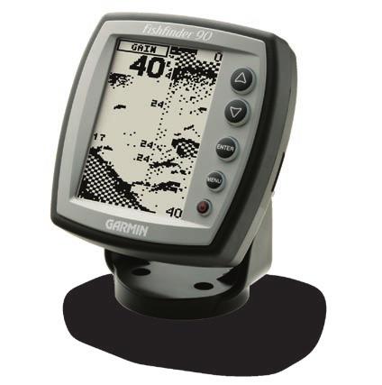
9 GETTING STARTED Using Simulator Mode Use simulator mode to practice and learn the operation of the Fishfinder. If the Fishfinder does not detect a transducer at startup, it automatically starts in simulator mode. While in simulator mode, the Fishfinder displays a bottom scene, and you can control the Fishfinder (except the Gain and Auto Gain options) just as if it were on the water. If no keys are pressed for two minutes, the Fishfinder automatically resets to default settings while in simulator mode. To exit simulator mode, turn off the Fishfinder. Water depth Water temperature at the transducer You see fish as arches or fish symbols in three sizes. Structure Simulator mode indicator Bottom shape and type Depth range Fishfinder 90/140 Owner s Manual 3


: A Fishfinder sonar unit I Trolling motor mount gasket B1 Swivel mount bracket J 5 mm Flat washers (2)")
 N 10-32 x 1.")
10 INSTALLING YOUR FISHFINDER INSTALLING YOUR FISHFINDER Make sure you completely read and understand all instructions before you install and use your Fishfinder. If you have problems, contact Product Support, or seek other professional assistance. You can install the Fishfinder hardware on a transom or on a trolling motor. Before installation, make sure the wiring harness can reach the Fishfinder and transducer locations. Check the packing list below. If you are missing any items, contact your Garmin dealer. Packing List (one of each, unless otherwise noted): A Fishfinder sonar unit I Trolling motor mount gasket B1 Swivel mount bracket J 5 mm Flat washers (2) (Fishfinder 140; optional for K 5 x 30 mm Screws (2) Fishfinder 90); or B2 Tilt mount L Lock nut bracket (Fishfinder 90) M 4 x 12 mm Screws (4) C Swivel base (Fishfinder 140) N x 1.75 Screw D Mounting knobs O 1/4" Cable clamps (2) E Mounting knob spacer P Plastic spacer F Snap ring Q 1/4" Rubber washer G Transducer with power cable R Cable tie, 5.6" (4) H Transducer mount S Cable tie, 20 4 Fishfinder 90/140 Owner s Manual J K L M A (Fishfinder 90) (Fishfinder 90 shown) G (Cable not shown) N O H C P Q B1 F (Fishfinder 140) R E I D B2 (Fishfinder 90) S
. 3. Place a 5 mm flat washer (J) on the 10-32 x 1.")

 2. Position the mount gasket (I) on the curved top of the transducer mount. 3.")
11 INSTALLING YOUR FISHFINDER Installing the Transducer Assembling the Transducer 1. Insert the rubber washer (Q) and plastic spacer (P) into the transducer (G) at the same time. DO NOT lubricate the rubber washer. 2. Route the cable toward the back of the transducer. Slide the transducer into the transducer mount (H). 3. Place a 5 mm flat washer (J) on the x 1.75" screw (N), and insert the screw through the transducer mount, spacer, and rubber washer. 4. Place the remaining 5 mm flat washer on the exposed end. Install the lock nut (L) tight. You can tighten the transducer further after installation on the boat. Cable tie slot Mounting the Transducer on a Trolling Motor 1. Slide the large cable tie (S) through the slot on the transducer mount (H) with the ridges of the band facing up until equal lengths extend on both sides of the mount. (NOTE: For cold water, or heavy timber or debris areas, a metal 4-5" worm gear clamp is recommended.) 2. Position the mount gasket (I) on the curved top of the transducer mount. 3. Place the transducer assembly against the motor body of the trolling motor, with the front of the transducer pointed away from the trolling motor propeller. Back of the transducer Fishfinder 90/140 Owner s Manual 5
12 INSTALLING YOUR FISHFINDER 4. Wrap the two ends of the cable tie around the motor body. Place the pointed end of the cable tie through the fastener hole on the opposite end and pull it through until it is snug but not tight. (The cable tie clicks when you pull it.) 5. Position the transducer so that it is parallel with the bottom when in use, and make sure the gasket is aligned properly. Pull the cable tie end until tight. Trim off the excess, if necessary. Tighten the locking nut until it touches the mounting bracket and then tighten 1/4 turn more. (Do not overtighten.) 6. Route the 30 (9 m) transducer cable using the supplied cable ties to secure the cable to the motor shaft. You can fill the forward-facing portion (except the cable tie pocket) of the transducer mount with sealant to avoid accumulating debris. Mounting the Transducer on a Transom When selecting a transom mount location, consider the following for optimal performance: For your sonar to operate properly, the transducer must be located in calm water. DO NOT mount the transducer behind strakes, rivet lines, struts, fittings, water intake, discharge ports, eroding paint, or anything that creates turbulence. Mount the transducer as close to the center of the boat as possible. DO NOT cut the transducer lead. (This voids your warranty.) DO NOT mount the transducer in locations where it might be jarred when launching, hauling, trailering, or storage. DO NOT mount the transducer in the path of the prop on single-drive boats. The transducer can cause cavitation that can degrade the boat s performance and damage the prop. On twin-drive boats, mount the transducer between the drives, if possible. 6 Fishfinder 90/140 Owner s Manual
13 Do not mount the transducer behind strakes, rivet lines, struts, fittings, water intakes or discharge ports. Mount the transducer parallel with the water line. Make sure the transducer is below water level when the boat is on plane at high speed. Apply marine sealant to all screw threads to prevent water from seeping into the transom. INSTALLING YOUR FISHFINDER To mount the transducer on a transom: Tool List (not included) drill, 3/8" wrench or socket, 5/32" and 1/8" drill bits, masking tape, #2 Phillips screwdriver, and marine sealant. 1. Position the transducer mount at the selected transom location. Make sure the transducer is parallel with the water line. Mark the center locations of each hole on the transducer mount. (See the figures on the next page.) 2. Using a 5/32" bit, drill the pilot holes approximately 1" (25 mm) deep at the marked locations. To avoid drilling the holes too deep, wrap a piece of tape around the bit at 1" from the point of the bit. 3. Apply marine sealant to the 5 x 30 mm screws. Attach the transducer assembly to the transom using the 5 x 30 mm screws. Adjust the transducer assembly to extend beyond the bottom of the transom approximately 1/8" (3 mm) on fiberglass hulls or 3/8" (10 mm) on aluminum hulls. Adjust the transducer assembly to be aligned parallel with the water. Fishfinder 90/140 Owner s Manual 7

14 INSTALLING YOUR FISHFINDER 4. Tighten the locking nut until it touches the mounting bracket, and then tighten 1/4 turn more. (Do not overtighten.) 5. Place the first cable clamp on the transducer cable approximately one third of the distance between the transducer and the top of the transom. Mark the location. Using a 1/8" bit, drill a pilot hole approximately 3/8" (10 mm) deep. 6. Attach the cable clamp using a 4 x 12 mm screw. Coat the screw with marine sealant before installation. Repeat steps 5 and 6 using the other cable clamp. 7. Route the transducer cable, as needed, to the Fishfinder. DO NOT CUT THE CABLE. Avoid routing the cable with electrical wires or other sources of electrical interference. OK Level Align with the transom bottom. The transducer should extend 1/8" below fiberglass hulls or 3/8" below aluminum hulls. Drill pilot holes here. Vertical Bottom of the transom Keep it parallel with the water line. 8 Fishfinder 90/140 Owner s Manual

15 INSTALLING YOUR FISHFINDER Installing the Fishfinder Unit Selecting a Fishfinder Location Select a Fishfinder installation location that allows you to view and operate it easily while operating the vessel. Select a mounting surface strong enough to support the weight of the Fishfinder and protect it from excessive vibration or shock. DO NOT mount the bracket in a location where the Fishfinder is exposed to extreme temperature conditions. When installing the mounting bracket, be sure to allow room to connect and rout the power cable. Mounting the Bracket Assembly Tool List (not included) drill, screwdriver (Phillips or standard), three #8 pan-head machine bolts with matching nuts and washers, and a 5/32" drill bit; or three #8 panhead, self-tapping screws and a 1/16" drill bit. To mount the bracket assembly: 1. Using the tilt mount bracket (Fishfinder 90) or the swivel base (Fishfinder 140; Fishfinder 90 option) as a template, mark the location of the three holes that you use to secure the bracket to the mounting surface. 2. If securing the base with machine bolts, drill three 5/32" holes at the locations you marked; or, if securing the base using self-tapping screws, drill 1/16" starter holes at the locations you marked. Drill starter holes no deeper than half the screw length. 3. Secure the tilt mount bracket or swivel base with three bolts or screws. DO NOT OVERTIGHTEN. 4. If you are using the swivel mount, place the swivel mount bracket over the swivel base and secure it with the short knob. Swivel mount bracket Tilt mount bracket Swivel base (Fishfinder 90) (Fishfinder 140; Fishfinder 90 option) Fishfinder 90/140 Owner s Manual 9

, rotate the swivel mount bracket by twisting it left or right. The bracket clicks as you turn it. Select a good viewing angle, and then tighten all knobs.")
16 INSTALLING YOUR FISHFINDER Installing the Unit on the Mount Bracket To install the Fishfinder on the mount bracket: 1. Align the slot on the back of the Fishfinder with the long mounting knob, and slide the Fishfinder into place. If necessary, adjust the long knob to spread the bracket arms apart. (Turn counter-clockwise to widen the bracket arms and clockwise to tighten.) 2. Adjust the Fishfinder angle, and tighten the long mounting knob until snug. 3. For the Fishfinder 140 (Fishfinder 90 option), rotate the swivel mount bracket by twisting it left or right. The bracket clicks as you turn it. Select a good viewing angle, and then tighten all knobs. Installing the Wiring Harness The Fishfinder comes with a wiring harness that connects the Fishfinder to power and the transducer with one easyto-remove connection. If it is necessary to extend the power wires, use 22 AWG wire. DO NOT cut the transducer cable, because this voids your warranty. If your boat has an electrical system, you might be able to wire the Fishfinder directly to an unused holder on your current fuse block. If you are using the boat s fuse block, remove the in-line fuse holder supplied with the Fishfinder. You can also wire the Fishfinder directly to the battery. CAUTION: The Fishfinder input voltage is volts DC. Do not exceed this voltage, because this can damage the Fishfinder and void the warranty. To install the wiring harness: 1. Determine the polarity of the power source using a test light or volt meter. 2. Install the red (+) wire on the positive fuse holder or battery terminal. 10 Fishfinder 90/140 Owner s Manual
17 INSTALLING YOUR FISHFINDER 3. Install the black (-) wire on the negative fuse holder or battery terminal. 4. Install a 2 Amp fuse in the fuse holder (fuse block only). 5. Align the notches on the cable plug and on the back of the Fishfinder. Insert the cable into the connector and turn the lock ring counter-clockwise until it stops. Testing the Transom Mount Installation Perform this test after you install the Fishfinder. Because you need water to carry the sonar signal, the Fishfinder does not function properly with the transducer out of the water. When you place your boat in the water, CHECK FOR LEAKS around the screw holes that are below the water line. DO NOT leave your boat in the water for an extended period of time without checking for leaks. To test the transom mount installation: 1. Begin testing the installation at a slow speed. If the sonar appears to be working properly gradually increase the boat s speed observing the sonar s operation. If the sonar signal suddenly is lost or the bottom return is severely degraded, note the speed at which this occurs. 2. Return the boat to the speed at which the signal was lost. Make moderate turns in both directions, and see if the signal improves. 3. If the signal strength improves while turning, adjust the transducer so that it extends another 1/8" below the transom of the boat. It might take several adjustments to eliminate the degradation. 4. If the signal does not improve, it might be necessary to move the transducer to a different location. Fishfinder 90/140 Owner s Manual 11

18 OPERATING YOUR FISHFINDER ENTER MENU OPERATING YOUR FISHFINDER Arrow keys the up and down Arrow keys select an item on a menu. Only the Fishfinder 140 has the right and left Arrow key that cycles through the Main menu options. ENTER key confirms a selection. MENU key shows or exits a menu. Power key turns the Fishfinder on or off and controls the screen backlight. Understanding Basic Functions To turn on the Fishfinder: Press and release the Power key. To turn off the Fishfinder: Press and hold the Power key. To change the backlight level: Press the Power key repeatedly to cycle between off, low, and high. To view or change settings for your Fishfinder, you can use two menus: the Main menu and the Setup menu. To change a setting: 1. Press MENU. The Main menu appears. 2. Use the Arrow keys to move the selection arrow to an option, and press ENTER. The settings appear. If you select Setup, the Setup menu appears. See Using the Setup Menu on page 14. (Fishfinder 140 is shown.) 12 Fishfinder 90/140 Owner s Manual
19 OPERATING YOUR FISHFINDER 3. To select a setting, use the Arrow keys to move the selection arrow, and press ENTER. (When you reach the end of a menu, the selection arrow wraps to the beginning.) Press and hold an Arrow key to rapidly advance the selection speed. 4. To close a setting or a menu, press MENU. Using the Main Menu From the Main menu, you can change the Range, Gain, Scroll, Zoom, and View settings. To view the current menu settings, press MENU. To quickly change a setting for the current option that appears in the upper-left corner of the screen (for example, the Range option in the above screen), press an Arrow key. Options and Settings The following settings reset to the system defaults each time you turn on the Fishfinder. Range sets the maximum depth that you want the Fishfinder to display. Auto (default) automatically tracks the bottom, or you can set the range, feet. Gain controls the sensitivity of the Fishfinder s sonar receiver. Auto (default) automatically sets the sonar sensitivity, or you can set the gain. To see more detail on the screen, increase the receiver sensitivity by selecting a higher gain. If there is too much detail or if the screen is cluttered, lower the sensitivity (lower the gain) to increase the clarity of the screen. To exit any window, press MENU. Fishfinder 90/140 Owner s Manual 13
20 OPERATING YOUR FISHFINDER Scroll sets the rate that the graph scrolls from right to left. If you are sitting still or the graph is moving too fast, slowing or pausing the graph can help. The settings are Ultra, Fast (default), Medium, Slow, and Paused. Zoom sets the zoom level for the screen. Off is the default. View when you select a 2X or 4X Zoom setting, you can select a specific area to view on the screen. You can also allow the Fishfinder to automatically select a zoomed viewing area based on the bottom. Using the Setup Menu To access the Setup menu: 1. Press MENU. The Main menu appears. 2. Use the Arrow keys to move the selection arrow to Setup, and press ENTER. The options appear. Options and Settings Your changes to the following settings are used until you set the System Defaults option to Yes. Alarms Battery controls an alarm that sounds when the battery is reaching a critical state of discharge. The settings are Off (default) and volts remaining. Shallow sets an alarm for the shallow water warning at a specific depth. The settings are Off (default) and feet. Deep sets an alarm for the deep water warning at a specific depth. The settings are Off (default) and feet. Fish turns on or off (default) an alarm that sounds when the Fishfinder detects what it determines to be a fish. 14 Fishfinder 90/140 Owner s Manual
21 OPERATING YOUR FISHFINDER Graphs Fish ID sets how the Fishfinder displays underwater targets and background information. If you select a fish symbol, the screen displays only the information related to that symbol (large, medium, and small sizes). When using wide beam, fish symbols that are to the sides of the boat appear hollow. Those that are directly below the boat appear as solid black fish symbols. OFF (default) the Fishfinder displays all of the available information about the underwater environment. suspended targets appear as symbols. No background information appears. the same as above with the target depth shown. suspended targets appear as symbols. Background information appears, making fish identification easier. the same as above with the target depth shown. Beam controls the angle of the transducer beam. Wide beam allows you to see more fish in shallow water, even off the sides of the boat. You can also choose Narrow (default) beam. Whiteline sets how the Fishfinder shows information about the bottom type. Off the bottom return appears as solid black. Whiteline Off Whiteline On On (default) the bottom return appears as a grayscale pattern and can help to determine bottom hardness. A hard bottom displays a thicker bottom layer. A soft bottom appears as a thinner bottom layer. Fishfinder 90/140 Owner s Manual 15
22 OPERATING YOUR FISHFINDER Auto Gain controls the aggressiveness of the Auto Gain. The higher the setting, the greater the number of targets appear on the screen. The lower the setting, the less clutter on the screen. The settings are High, Medium (default), and Low. Numbers Size sets the appearance of depth, temperature, and battery numbers. The settings are Small and Large (default). Battery sets whether the current battery voltage appears on the screen. The settings are Hide (default) and Show Water Temperature sets whether the water temperature appears on the screen. This appears only if you have a temperature-capable transducer. The settings are Hide and Auto (default). Units Depth sets the measurements in Feet (default), Meters, or Fathoms. Temperature sets the water temperature units. The settings are Fahrenheit (default) and Celsius. System Simulator controls the simulator mode. The settings are Off and On (default). See page 3 for more information. Language sets your language choice. Beeper controls all Fishfinder sounds. The settings are Off and On (default). Contrast adjusts the contrast of the screen to compensate for light levels or viewing angles. Use the Arrow keys to increase or decrease the screen contrast. Defaults restores all default settings. 16 Fishfinder 90/140 Owner s Manual
23 APPENDIX Specifications Fishfinder 90 Size: 4.7" W x 4.9" H x 2.43" D (11.9 x 12.4 x 6.1 cm) Weight: 15.5 oz Display: 2.0" W x 3.3" H (5.0 x 8.4 cm), 3.9" (9.9 cm) diagonal, 64 x 128 pixels, black-and-white FSTN display Usage: 3.5 watts maximum, Nominal: Amps Fishfinder 140 Size: 6.1" W x 4.9" H x 2.6" D (15.5 x 12.5 x 6.6 cm) Weight: 18.7 oz. Display: 3.2" W x 3.1" H (8.1 x 7.9 cm), 4.7" (9.9 cm) diagonal, 128 x 240 pixels, 4-level gray scale FSTN display Usage: 8 watts maximum, Nominal: Amps Fishfinder 90 and Fishfinder 140 Case: Fully Gasketed, high-impact plastic alloy Waterproof: IEC 529, level IPX-7 (submerged to 1 meter for 30 minutes) Temperature Range: +5 F to 158 F (-15 C to 70 C) APPENDIX Internal memory backup to retain user settings Input: 10 to 18 VDC with high voltage protection Sonar Power Output: 100 watts (RMS), 800 watts (peak-to-peak) Frequency: 80 khz (wide) and 200 khz (narrow) Depth: 600 foot max depth. (Depth capacity is dependent on water salinity, bottom type, and other water conditions.) Specifications are subject to change without notice. Optional Accessories Purchase the following optional accessories on the Garmin Web site: Swivel mount for the Fishfinder 90 allows your Fishfinder 90 to tilt and swivel on its mounting bracket. Portable case with battery pack and suction mount transducer makes your Fishfinder portable, so that it can go on any boat, with no installation (requires eight D-cell batteries, not included). Flush mounting kit mounts your fishfinder flush on the bulkhead or cabin wall. Simply press the side clips to release the Fishfinder so you can take it with you. Protective cover protects your product when you are not using it. Fishfinder 90/140 Owner s Manual 17
24 APPENDIX Software License Agreement BY USING THE FISHFINDER, YOU AGREE TO BE BOUND BY THE TERMS AND CONDITIONS OF THE FOLLOWING SOFTWARE LICENSE AGREEMENT. PLEASE READ THIS AGREEMENT CAREFULLY. Garmin grants you a limited license to use the software embedded in this device (the Software ) in binary executable form in the normal operation of the product. Title, ownership rights, and intellectual property rights in and to the Software remain in Garmin. You acknowledge that the Software is the property of Garmin and is protected under the United States of America copyright laws and international copyright treaties. You further acknowledge that the structure, organization, and code of the Software are valuable trade secrets of Garmin and that the Software in source code form remains a valuable trade secret of Garmin. You agree not to decompile, disassemble, modify, reverse assemble, reverse engineer, or reduce to human readable form the Software or any part thereof or create any derivative works based on the Software. You agree not to export or re-export the Software to any country in violation of the export control laws of the United States of America. Limited Warranty This Garmin product is warranted to be free from defects in materials or workmanship for one year from the date of purchase. Within this period, Garmin will at its sole option repair or replace any components that fail in normal use. Such repairs or replacement will be made at no charge to the customer for parts or labor, provided that the customer shall be responsible for any transportation cost. This warranty does not cover failures due to abuse, misuse, accident or unauthorized alteration or repairs. THE WARRANTIES AND REMEDIES CONTAINED HEREIN ARE EXCLUSIVE AND IN LIEU OF ALL OTHER WARRANTIES EXPRESS OR IMPLIED OR STATUTORY, INCLUDING ANY LIABILITY ARISING UNDER ANY WARRANTY OF MERCHANTABILITY OR FITNESS FOR A PARTICULAR PURPOSE, STATUTORY OR OTHERWISE. THIS WARRANTY GIVES YOU SPECIFIC LEGAL RIGHTS, WHICH MAY VARY FROM STATE TO STATE. IN NO EVENT SHALL GARMIN BE LIABLE FOR ANY INCIDENTAL, SPECIAL, INDIRECT OR CONSEQUENTIAL DAMAGES, WHETHER RESULTING FROM THE USE, 18 Fishfinder 90/140 Owner s Manual
25 APPENDIX MISUSE, OR INABILITY TO USE THIS PRODUCT OR FROM DEFECTS IN THE PRODUCT. Some states do not allow the exclusion of incidental or consequential damages, so the above limitations may not apply to you. Garmin retains the exclusive right to repair or replace the unit or software or offer a full refund of the purchase price at its sole discretion. SUCH REMEDY SHALL BE YOUR SOLE AND EXCLUSIVE REMEDY FOR ANY BREACH OF WARRANTY. To obtain warranty service, contact your local Garmin authorized dealer or call Garmin Product Support for shipping instructions and an RMA tracking number. The unit should be securely packed with the tracking number clearly written on the outside of the package. The unit should then be sent, freight charges prepaid, to any Garmin warranty service station. A copy of the original sales receipt is required as the proof of purchase for warranty repairs. Garmin International, Inc E 151st Street, Olathe, Kansas U.S.A. Tel. 913/ , Fax. 913/ Garmin (Europe) Ltd. Unit 5, The Quadrangle, Abbey Park Industrial Estate, Romsey, SO51 9DL U.K. Tel. 44/ , Fax 44/ Online Auction Purchases: Products sold through online auctions are not eligible for rebates or other special offers from Garmin. Online auction confirmations are not accepted for warranty verification. To obtain warranty service, an original or copy of the sales receipt from the original retailer is required. Garmin will not replace missing components from any package purchased through an online auction. International Purchases: A separate warranty is provided by international distributors for units purchased outside the United States. This warranty is provided by the local in-country distributor and this distributor provides local service for your unit. Distributor warranties are only valid in the area of intended distribution. Units purchased in the United States or Canada must be returned to the Garmin service center in the United Kingdom, the United States, Canada, or Taiwan for service. The Garmin Fishfinder has no user-serviceable parts. Should you ever encounter a problem with your unit, please take it to an authorized Garmin dealer for repairs. The Fishfinder is fastened shut with screws. Any attempt to open the case to change or modify the unit in any way will void your warranty and may result in permanent damage to the equipment. Fishfinder 90/140 Owner s Manual 19
26 INDEX INDEX A accessories 17 alarms 14 battery 14 deep 14 fish 14 shallow 14 Anti-reflective coating ii arrow keys 12 assembling the transducer 5 B backlight 12 battery alarm 14 battery number 16 beeper setting 16 bracket assembly 9 C cleaning the case and screen ii contrast setting 16 D defaults setting 16 depth units 16 E enter key 12 F fish alarm 14 fish ID graph 15 G gain 13 graphs 15 auto gain 16 beam 15 fish ID 15 Whiteline 15 I installing the Fishfinder unit 9 the transducer 5 the unit on the mount bracket 10 the wiring harness 10 your Fishfinder 4 K key arrow 12 enter 12 menu 12 L language setting 16 limited warranty 18 location, installation 9 M menu main 13 setup 14 menu key 12 mounting bracket 10 mounting the bracket assembly 9 mounting the transducer on a transom 7 mounting the transducer on a trolling motor 5 N numbers 16 battery 16 water temperature 16 O optional accessories 17 P packing list 4 product registration i 20 Fishfinder 90/140 Owner s Manual
27 INDEX R range 13 registration, product i S screen, understanding the 1, 3 scroll 14 selecting a transom mount location 6 setting, changing a 12 setup menu 14 setup menu option 12 shallow alarm 14 simulator mode 3 simulator setting 16 size, number 16 software license agreement 18 sonar 1 specifications 17 storage ii swivel mount bracket 9, 10 T temperature number 16 temperature units 16 testing the transom mount installation 11 transducer 2 assembling 5 installing 5 mounting on a transom 6 mounting on a trolling motor 5 transom mount installation 11 U units 16 depth 16 temperature 16 V view 14 W warning statement iv warranty, limited 18 water immersion ii water temperature number 16 whiteline 15 wiring harness 10 Z zoom 14 Fishfinder 90/140 Owner s Manual 21
28
29
30
31
32 For the latest free software updates (excluding map data) throughout the life of your Garmin products, visit the Garmin Web site at Garmin Ltd. or its subsidiaries Garmin International, Inc East 151 st Street, Olathe, Kansas 66062, U.S.A. Garmin (Europe) Ltd. Unit 5, The Quadrangle, Abbey Park Industrial Estate, Romsey, SO51 9DL, U.K. Garmin Corporation No. 68, Jangshu 2 nd Road, Shijr, Taipei County, Taiwan Part Number Rev. A
Fishfinder 160C color sonar. owner s manual
 Fishfinder 160C color sonar owner s manual Copyright 2006 Garmin Ltd. or its subsidiaries Garmin International, Inc. 1200 East 151 st Street, Olathe, Kansas 66062, USA Tel. 913/397.8200 or 800/800.1020
GPSMAP 2206/2210 & GPS 17
 GPSMAP 2206/2210 & GPS 17 installation instructions Graphic to be replaced Copyright 2006 Garmin Ltd. or its subsidiaries Garmin International, Inc. 1200 East 151 st Street, Olathe, Kansas 66062, U.S.A.
Part Number Rev. B. Unit housing Hex nuts. Unit Rubber seal Hex bolts. Hex bolts. Hex nuts. Figure 1
 Installing the Flush Mount Kit Use this kit to flush mount a GPSMAP 500 series unit into a flat panel. Select an appropriately sized location for the unit. Use the Flush Mount Template provided to determine
set up and go! 200 Series nüvi affordable navigation
 nüvi set up and go! 200 Series affordable navigation Getting Started What Is in the Box? nüvi unit Suction cup mount to mount the nüvi to your windshield. Vehicle power cable to charge/power your nüvi
FOR ALL SINGLE MOTOR UNITS INSTALLATION AND OPERATING INSTRUCTIONS REV 12/15 89
 FOR ALL SINGLE MOTOR UNITS INSTALLATION AND OPERATING INSTRUCTIONS REV 12/15 89 INTRODUCTION Congratulations, you have just purchased one of the most unique trolling motors available today. It is the Original
LDT Digital Temperature Gauge. Installation & Operation Instructions
 Pub. 988-0099-071 LDT-3200 Digital Temperature Gauge Installation & Operation Instructions The LDT-3200 combines a temperature gauge, voltmeter and clock in one housing. It displays the temperature in
Panoptix PS21-TR. Installation Instructions. Important Safety Information. Registering Your Device
 Panoptix PS21-TR Installation Instructions Important Safety Information WARNING See the Important Safety and Product Information guide in the chartplotter or fishfinder product box for product warnings
zūmo 200 series quick start manual for use with the zūmo 220
 zūmo 200 series quick start manual for use with the zūmo 220 GPS antenna Your zūmo Power button: Press and hold to turn on/off the zūmo. Press quickly to adjust the backlight brightness. Speaker Battery
INSTALLATION AND OPERATING INSTRUCTIONS
 DUAL AND TRITON 2 AND 3 MOTOR SERIES Model 65-0110 Freshwater Model 65-1110 Saltwater 24 volt 110 lb. Thrust Model 65-0165 Freshwater Model 65-1165 Saltwater 24 volt 165 lb. Thrust INSTALLATION AND OPERATING
PIRANHA I & 2 INSTALL GUIDE
 TOP Use 5/32" drill bit DO NOT LET DEADRISE INTERSECT THIS LINE PLACE EITHER CORNER ON DEADRISE ANGLE PIRANHA I & 2 INSTALL GUIDE Two components need to be installed on the boat: the transducer and the
MODEL FIXED MOTOR BRACKET
 MODEL 55-0027 FIXED MOTOR BRACKET INSTALLATION MANUAL REV 12/15 CUSTOMER MUST RECEIVE THIS MANUAL AFTER INSTALLATION INSTALLATION PROCEDURES Congratulations, you have just purchased one of the finest outboard
Model AS-FM64 Wall Mount. Full Motion Television Wall Mount
 Model AS-FM64 Wall Mount Full Motion Television Wall Mount Getting Started Introduction Congratulations on the purchase of your new Audio Solutions AS-FM64 Television Wall Mount. For maximum benefit, please
Model T2642 Wall Mount. Television Wall Mount with Tilt Option
 Model T2642 Wall Mount Television Wall Mount with Tilt Option Getting Started Introduction Congratulations on the purchase of your new Audio Solutions T2642 Television Wall Mount. For maximum benefit,
PIRANHA I & 2 INSTALL GUIDE
 PIRANHA I & 2 INSTALL GUIDE Two components need to be installed on the boat: the transducer and the control head. The control head displays sonar information, the transducer sends and receives sonar signals
3-LIGHT VANITY BAR ITEM # MODEL #34674 ATTACH YOUR RECEIPT HERE. Serial Number. Purchase Date
 ITEM #351-0599 3-LIGT VANITY BAR MODEL #34674 ATTAC YOUR RECEIPT ERE Serial Number Purchase Date Questions, problems, missing parts? Before returning to your retailer, call our customer service department
Model FM2642 Wall Mount. Full Motion Television Wall Mount
 Model FM2642 Wall Mount Full Motion Television Wall Mount Getting Started Introduction Congratulations on the purchase of your new Audio Solutions FM2642 Television Wall Mount. For maximum benefit, please
POST LANTERN ITEM # MODEL #39487 ATTACH YOUR RECEIPT HERE. Serial Number. Purchase Date
 ITEM #356-4981 POST LANTERN MODEL #39487 ATTACH YOUR RECEIPT HERE Serial Number Purchase Date Questions, problems, missing parts? Before returning to your retailer, call our customer service department
Model AS-RC3260 TV Cart. Rolling Cart for Audio Mount System & Flat Panel TVs
 Model AS-RC3260 TV Cart Rolling Cart for Audio Mount System & Flat Panel TVs GETTING STARTED Introduction Congratulations on the purchase of your new Helios AS-RC3260 Rolling Cart. For maximum benefit,
INSTALLATION AND OPERATING INSTRUCTIONS
 Auxiliary Outboard Motor Bracket for the following products: 55-0010, 55-0012, 55-0020A, 55-0021, 55-0022 INSTALLATION AND OPERATING INSTRUCTIONS 55-0010 55-0012 & 55-0021 55-0020A REV. 12/15 AUXILIARY
SWIM PLATFORM BRACKET
 55-0030 SWIM PLATFORM BRACKET FOR LIGHT WEIGHT 4 STROKE ENGINES UP TO 20 HP AND 195 LBS. INSTRUCTION MANUAL REV. 12/15 4-Stroke Auxiliary Outboard Motor Bracket Mounting Instructions for Proper Location
Installation & Operation Instructions. Deluxe LED Spot Light
 Installation & Operation Instructions Deluxe LED Spot Light 405626-3 To avoid the risk of accidents or damage to this product, it is essential to read these instructions thoroughly SDG Edition before this
60 PSI Boost Gauge. For Product Numbers: MT-DV01_60, MT-WDV01_60
 60 PSI Boost Gauge For Product Numbers: MT-DV01_60, MT-WDV01_60 Red: 12v Constant (un-switched) Source (+) Orange: 12v Dimmer (switched) Source (+) (optional) White: 12v Ignition (switched) Source (+)
OPERATION AND MAINTENANCE
 Table of Contents GENERAL INFORMATION INTRODUCTION... 1 Operating Specifications... 1 FEATURES... 1 SAFETY PRECAUTIONS... 2 SET-UP... 2 OPERATION AND MAINTENANCE TESTING AN IGNITION MODULE OR IGNITION
Customer Support
 Portable auxiliary air tanks owner's Manual aux05 aux05a aux10 WWW.CALIFORNIAAIRTOOLS.COM Customer Support 1-866-409-4581 TAbLe OF CONTeNTS INTROduCTION IntroductIon Important Safety InStructIonS components
DWS404 DWS524 DWS654 DWS684 DWS694. DWS SERIES INSTALLATION/OWNER'S MANUAL Car Audio Speakers
 DWS404 DWS524 DWS654 DWS684 DWS694 DWS SERIES INSTALLATION/OWNER'S MANUAL Car Audio Speakers PREPARATION Safety Guidelines Thank you for purchasing the DWS Series car speakers. Although Dual has attempted
Swing Arm Magnifying Lamp
 Owner s Manual & Safety Instructions Save This Manual Keep this manual for the safety warnings and precautions, assembly, operating, inspection, maintenance and cleaning procedures. Write the product s
INSTALLATION INSTRUCTIONS
 INSTALLATION INSTRUCTIONS Thank you for purchasing ACCESS Original Roll-Up Cover. Agri-Cover, Inc. proudly manufactured this cover using superior quality materials and workmanship. With proper care, your
LU27 Series Quick Start
 Ultrasonic Liquid Level Transmitter LU27 Series Quick Start 2016 Flowline, Inc. All Rights Reserved Made in USA Flowline, Inc. 10500 Humbolt Street, Los Alamitos, CA 90720 p 562.598.3015 f 562.431.8507
Digital echo-charge. Owner s Manual. Xantrex Digital echo-charge Battery Charger
 Digital echo-charge Owner s Manual Xantrex Digital echo-charge Battery Charger INTRODUCTION The Xantrex Digital echo-charge is specially developed for charging an auxiliary battery with Freedom TM or Fleet
BEAMER MODEL VDC Spotlight with joystick control panel MODEL VDC Spot/flood light with joystick control panel
 formerly a marinco.com product 502-2 installation & 503-2 instructions 502-2 24 VDC Spotlight with joystick control panel 502-3 24 VDC Spot/flood light with joystick control panel BEAMER MODEL 502-2 24
Toro Sprayer Calibration Tool
 Commercial Products Toro Sprayer Calibration Tool User Guide & Installation Instructions Toro Sprayer Calibration Tool 1 Table of Contents Introduction... 2 Program Instructions... 4 Toro Software End
DUAL WIDEBAND AIR/FUEL RATIO GAUGE Product Numbers: GS-W702W_Dual, GS-C702W_Dual, GS-T702W_Dual
 Installation Instructions Tech Support: 856.768.8300 TechSupport@GlowShiftGauges.com DUAL WIDEBAND AIR/FUEL RATIO GAUGE Product Numbers: GS-W702W_Dual, GS-C702W_Dual, GS-T702W_Dual (1) Gauge (2) Controllers
NX Combi Transducer. Installation and Operation Manual English
 NX Combi Transducer Installation and Operation Manual Start pack 3 1 Start pack 3 Edition: April 2007 2 Start pack 3 1 Registration... 3 2 Installation... 4 3 Mounting of Transom transducer... 4 3.1 Applications...
6.5 x 5.25 Classic Vamp Spin Speakers
 w w w.ro swellmarine. co m 6.5 x 5.25 Classic Vamp Spin Speakers Installation & Usage Instructions Part # C920-1824 Information: info@roswellmarine.com If you have any questions please call : 1-321-638-1331
PVI 60KW, PVI 82KW, PVI 95KW
 PVI 60KW PVI 82KW PVI 95KW WARRANTY MANUAL Commercial, Grid-Tied Photovoltaic Inverters 2008, Solectria Renewables LLC Subject to Change DOC-020099 rev 024 1 1 Product Warranty & RMA Policy Warranty Policy
MCL-3000 SERIES OIL TEMP PART# MCL-3K-TMP
 MCL-3000 SERIES OIL TEMP PART# MCL-3K-TMP Thank you for purchasing the Dakota Digital MCL-3K-TMP gauge for your Harley Davidson Touring bike. This gauge is designed to be a direct, plug in replacement
PVI 1800/PVI Residential/Commercial Grid-Tied Photovoltaic Inverter WARRANTY MANUAL. Subject to Change REV , Solectria Renewables
 PVI 1800/PVI 2500 WARRANTY MANUAL Residential/Commercial Grid-Tied Photovoltaic Inverter 2009, Solectria Renewables Subject to Change REV 10.09 1 Product Warranty & RMA Policy 1.1 Warranty Policy The Solectria
1. Testing the Transducer Prior to Installation
 1 Overview Before you start installation, we encourage you to read these instructions carefully in order to get the full benefit from your Humminbird accessory. Thru-Hull Installation NOTE: This type of
MODEL MODEL S
 MODEL 55-0502 MODEL 55-0503 S INSTALLATION AND OPERATING INSTRUCTIONS CUSTOMER MUST RECEIVE THIS MANUAL AT TIME OF SALE OR AFTER INSTALLATION Rev 12/15 INTRODUCTION Congratulations, you have just purchased
Owners Manual. LifeGuard Power Lift Model # Rev. 2/1/13
 Owners Manual LifeGuard Power Lift Model #100287 Rev. 2/1/13 Table of Contents 1. ASSEMBLY INSTRUCTIONS 3-5 A. Lift Assembly 3 B. Setup 3 1. Clinch Pin Location Drawings 4 2. Down Tube and Seat Assembly
PIRANHA 5 INSTALLATION GUIDE
 PIRANHA 5 INSTALLATION GUIDE Two components need to be installed on the boat: the transducer and the control head. The control head displays sonar information, the transducer sends and receives sonar signals
Installation and Operation Manual
 Installation and Operation Manual * Read all installation instruction and warranty information prior to beginning installation * XeVision HID landing and taxi lights are for experimental aircraft only
LifeGuardLift. LifeGuard Power Lift Model #100287A OWNERS MANUAL. Rev: 2/14/11
 LifeGuardLift OWNERS MANUAL LifeGuard Power Lift Model #100287A Rev: 2/14/11 Table of Contents 1. ASSEMBLY INSTRUCTIONS A. Lift Assembly B. Setup C. Disassembly 2. CONTROL SYSTEM A. Batteries B. Battery
Automatic Emergency Light
 Automatic Emergency Light Item 38013 Read this material before using this product. Failure to do so can result in serious injury. Save this manual. When unpacking, make sure that the product is intact
PACIFICA Shower Cabin Installation Instructions
 PACIFICA Shower Cabin Installation Instructions IMPORTANT Please read carefully the following instructions before installing your shower cabin. If you have any questions on this shower cabin installation
INW Panel Meter Reading an INW PT12 Sensor
 INW Panel Meter Reading an INW PT12 Sensor PROUDLY MADE IN THE USA ISO 9001:2008 Certified Company Table of Contents Introduction...5 What is an INW Panel Meter for an INW PT12 Smart Sensor?...5 Initial
10 Year Limited Warranty
 Power. On Your Terms. 10 Year Limited Warranty PHI 2.7 TM PHI 3.5 TM 60A SIMPLIPHI POWER, INC. REV020618 10 Year Limited Warranty: PHI 2.7 TM PHI 3.5 TM 60A 24V 48V Limited Pro-Rated Warranty Coverage
Shower System. Dual Head INSTRUCTION GUIDE
 INSTRUCTION GUIDE Step-By-Step Illustrated Installation Instructions Jet Cleaning Instructions Proper Finish Care Limited Warranty Read these instructions carefully before installing your new shower system
LU23, LU28 & LU29 Series Quick Start
 Ultrasonic Liquid Level Transmitter LU23, LU28 & LU29 Series Quick Start 2016 Flowline, Inc. All Rights Reserved Made in USA Flowline, Inc. 10500 Humbolt Street, Los Alamitos, CA 90720 p 562.598.3015 f
6-12 WIDESPREAD 6-12 W. Cleopatra Series INSTRUCTION GUIDE SAVE THIS INSTRUCTION GUIDE
 INSTRUCTION GUIDE STEP-BY-STEP ILLUSTRATED INSTALLATION INSTRUCTIONS TROUBLE SHOOTING & REPAIR TIPS 20 YEAR LIMITED WARRANTY PROPER FINISH CARE Read these instructions carefully before installing your
END USER TERMS OF USE
 END USER TERMS OF USE The following is the End Users Terms of Use as it currently appears in the Mobileye User Manual and Warranty information. This is here for your review and information; it is subject
INSTALLATION INSTRUCTIONS FOR TRANSOM ADAPTOR. FOR MOTORS UP TO 20 HP Fits Panther Brackets , , ,
 INSTALLATION INSTRUCTIONS FOR 55-0023 TRANSOM ADAPTOR. FOR MOTORS UP TO 20 HP Fits Panther Brackets 55-0010, 55-0012, 55-0021, 55-0022 REV. 12/15 The TRANSOM ADAPTER allows the user to remove the outboard
Power. On Your Terms.
 Power. On Your Terms. 10 YEAR LIMITED WARRANTY PHI 1310 TM 1 SIMPLIPHI POWER, INC. REV102016 10 YEAR LIMITED WARRANTY: PHI 1310 TM LIMITED PRO-RATED WARRANTY COVERAGE The SimpliPhi Power PHI 1310 as supplied
DM1016S INSTALLATION/OWNER'S MANUAL 10" Marine DVC Subwoofer
 DM1016S INSTALLATION/OWNER'S MANUAL 10" Marine DVC Subwoofer DM1016S INSTALLATION Preparation/Installation Please read entire manual before installation. Before You Start Disconnect negative battery terminal.
2060F / 2062F / 2064F
 Operation & Installation Guide 060F / 06F / 064F DIGITAL ANTI-THEFT SAFE MANUAL # M08-070-000 Index / Overview of Your Safe INDEX Overview of Your Safe...1 Initial Set Up... Programming a Personal Passcode...
EchoPod. Technical Support. Model: DL14-(XX) Quick Start
 Quick Start") Technical Support For complete product documentation, video training, and technical support, go to www.flowline.com. For phone support, call 562-598-3015 from 8am to 5pm PST, Mon - Fri. (Please make sure
Technical Support For complete product documentation, video training, and technical support, go to www.flowline.com. For phone support, call 562-598-3015 from 8am to 5pm PST, Mon - Fri. (Please make sure
Installation Instructions
 Installation Instructions AMP RESEARCH Power Step by Bestop Automatic Retracting Running Board Vehicle Application Nissan Titan King Cab 2004 and newer (5 ft.) Part Number: 75106-01 Nissan Titan Crew Cab
Internal PVC Rod-Style Fluid Level Sensor
 Internal PVC Rod-Style Fluid Level Sensor New Providence Marine Systems INTERNAL PVC ROD SENSOR Copyright 2006 Topic Table of Contents Page 1:Introduction 2 2:Installation Guide 3 3:Limited Warranty 5
PIAA Multi-Fit 005/1100X Light Bracket Kits
 ENGLISH PIAA Multi-Fit 005/1100X Light Bracket Kits Thank you for your purchase. Please read all the instructions before beginning.! WARNING Lighting laws vary state to state, check your local laws before
EchoPod. DL10, DL14, DL24, DS14 & DX10 Series Quick Start. DL14-00 Shown Flowline, Inc. All Rights Reserved Made in USA
 EchoPod Ultrasonic Level Switch, Controller & Transmitter DL10, DL14, DL24, DS14 & DX10 Series Quick Start DL14-00 Shown 2016 Flowline, Inc. All Rights Reserved Made in USA Flowline, Inc. 10500 Humbolt
Model FM2260 Wall Mount. Full Motion Television Wall Mount
 Model FM2260 Wall Mount Full Motion Television Wall Mount Getting Started Introduction Congratulations on the purchase of your new udio Solutions FM2260 Television Wall Mount. For maximum benefit, please
Installation Power Management Unit Battery Cables and Battery Harness
 Installation Power Management Unit Battery Cables and Battery Harness Important Safety Messages SAVE THESE INSTRUCTIONS - This manual contains important instructions that should be followed during installation
EchoPod. UG06 & UG12 Series Quick Start Flowline, Inc. All Rights Reserved Made in USA. Ultrasonic Liquid Level Transmitter
 EchoPod Ultrasonic Liquid Level Transmitter UG06 & UG12 Series Quick Start 2017 Flowline, Inc. All Rights Reserved Made in USA Flowline, Inc. 10500 Humbolt Street, Los Alamitos, CA 90720 p 562.598.3015
MODEL 22040, REMOTE CONTROL STAINLESS STEEL OR CHROME SPOT/FLOOD LIGHT INSTALLATION AND OPERATION INSTRUCTIONS IMPORTANT!
 R R MODEL 22040, 22044 REMOTE CONTROL STAINLESS STEEL OR CHROME SPOT/FLOOD LIGHT INSTALLATION AND OPERATION INSTRUCTIONS IMPORTANT! READ THESE INSTRUCTIONS BEFORE INSTALLING AND USING THIS PRODUCT. KEEP
series USER MANUAL
 888 534-5994 4000 series USER MANUAL Contents Here s all the information you need for setting and operating your new Lathem time recorder. Service information is also included in this manual, in case any
READ AND SAVE THESE INSTRUCTIONS. ComfortBreeze UV360-1 SYSTEM 24V Ultra-Violet Air Cleaner. Trion
 READ AND SAVE THESE INSTRUCTIONS ComfortBreeze UV360-1 SYSTEM 24V Ultra-Violet Air Cleaner Trion www.trioniaq.com Installation, Operation, & Maintenance Manual 1. Warranty 2. Safety & Warnings ComfortBreeze
WARNING ATTENTION. Please read this information carefully before operating your safe.
 WARNING Please use caution when unbolting this safe from its shipping skid. Sports Afield recommends anchoring your safe to the floor. Failure to do so may cause the safe to fall forward. ATTENTION Please
2087F-BD / 2092F-BD. COMBINATION WATERPROOF FIRE SAFE with Ready-Seal. Operation & Installation Guide. Manual # M
 Operation & Installation Guide 2087F-BD / 2092F-BD Manual # M08-0274-008 www.firstalert.com COMBINATION WATERPROOF FIRE SAFE with Ready-Seal Manual # M08-0274-008 L-10-XZ Index / Overview of Your Safe
37SCENE 46SCENE 79SCENE
 Installation and Operation Instructions LED SCENE LIGHT LED SCENE LIGHT 37SCENE 46SCENE 79SCENE 37SCENE 46SCENE Introduction The 37SCENE, 46SCENE, 79SCENE LED Scene Lights are designed for the emergency
Slimline Duals Installation Instructions Harley-Davidson Touring Models 2009-Current
 Slimline Duals Installation Instructions Harley-Davidson Touring Models 2009-Current Thank you for buying a Rinehart Racing exhaust system. We are committed to providing premium products that with proper
ELECTROSTEER MODEL A FRESHWATER MODEL A SALTWATER
 ELECTROSTEER MODEL 55-0100A FRESHWATER MODEL 55-0101A SALTWATER INSTALLATION AND OPERATING INSTRUCTIONS CUSTOMER MUST RECEIVE THIS MANUAL AT TIME OF SALE OR AFTER INSTALLATION Rev 01/13 P/N 99-55276 INTRODUCTION
TC26-B Vehicle Sensor
 Section 1 General Description The Model TC26-B is a microprocessor controlled vehicle sensor with a variable range. It is designed to trigger the operation of a traffic controller. The TC26-B will only
V HUB INSTALLATION AND OPERATING INSTRUCTIONS
 2008 Wood Court Plant City, FL 33563 USA Phone (813)752-3711 Fax (813)752-2818 http:\\www.sensenich.com Composite Airboat Propellers V HUB INSTALLATION AND OPERATING INSTRUCTIONS CAUTION: Failure to follow
INSTALLATION/OWNER'S MANUAL DP " Woofer in Enclosure
 INSTALLATION/OWNER'S MANUAL DP1000 10" Woofer in Enclosure Installation Thank you for purchasing the DP1000 10" Woofer with enclosure. Although Dual has attempted to make sure all of the information contained
This Manual Provides Installation and Operation Instructions for the following models:
 OWNER'S MANUAL Capstan Powered Lift Assist This Manual Provides Installation and Operation Instructions for the following models: CAPSTAN 1000 CAPSTAN 300 QUICK CATCH POT PULLER pwcs101 12 Volt Powered
Light Duty Electronic Air Command
 2491 PSI BAR Light Duty Electronic Air Command INSTALLATION INSTRUCTIONS Congratulations on your purchase of a Light Duty Electronic Air Command kit. This kit was designed to provide inflation control
COAXIAL SPEAKERS FI4-F3, FI5-F3, FI57-F3, FI6-F3, FI69-F3
 COAXIAL SPEAKERS FI4-F3, FI5-F3, FI57-F3, FI6-F3, FI69-F3 2 OWNERS MANUAL Congratulations on purchasing your FLI speakers. Please read this manual in order to fully understand how to get the best results
3 LIGHT VANITY ITEM # MODEL #37314 ATTACH YOUR RECEIPT HERE. Serial Number. Purchase Date
 ITEM #351-0593 3 LIGHT VANITY MODEL #37314 ATTAH YOUR REEIPT HERE Serial Number Purchase Date Questions, problems, missing parts? Before returning to your retailer, call our customer service department
BAK1500 INSTALLATION/OWNER'S MANUAL Compact Amplified Subwoofer
 BAK1500 INSTALLATION/OWNER'S MANUAL Compact Amplified Subwoofer PREPARATION Getting Started Thank you for purchasing the Dual BAK1500 compact amplified subwoofer. Although Dual has attempted to ensure
Nissan Armada up A Nissan Titan Crew Cab up A Nissan Titan King Cab up A
 INSTALLATION GUIDE APPLICATION MODEL YR PART # Nissan Armada 200 - up 75110-01A Nissan Titan Crew Cab 200 - up 75110-01A Nissan Titan King Cab 200 - up 75110-01A INSTALLATION TIME 3:00 hrs SKILL LEVEL
XP88 & XP89 Series Quick Start
 Ultrasonic Liquid Level Transmitter XP88 & XP89 Series Quick Start 2016 Flowline, Inc. All Rights Reserved Made in USA Flowline, Inc. 10500 Humbolt Street, Los Alamitos, CA 90720 p 562.598.3015 f 562.431.8507
Spotlight 1,000,000 Power Series Cordless Rechargeable
 VEC156CFL_Manual_012405 1/24/05 4:29 PM Page iv VEC156 Spotlight 1,000,000 Power Series Cordless Rechargeable OWNER S MANUAL & WARRANTY INFORMATION 53SB E231887 IMPORTANT SAFETY INFORMATION, SAVE THESE
USER GUIDE 1 USER GUIDE
 USER GUIDE 1 USER GUIDE 1 TABLE OF CONTENTS IN THE BOX...3 NAVIGATING THE MENUS...3 MENU LAYOUT...3 UPDATE YOUR PROGRAMMER...4 CONNECT WITH THE MOTORCYCLE...5 TUNE YOUR MOTORCYCLE...6 ADDITIONAL FEATURES...8
Motorized Stainless 2-Way Valves
 Installation and Operation Manual Motorized Stainless 2-Way Valves Safety Valve ETV Applications WARNING This Heat-Timer valve is strictly an operating valve; it should never be used as a primary limit
AUTOMATIC SUBMERSIBLE UTILITY PUMP
 AUTOMATIC SUBMERSIBLE UTILITY PUMP Zoeller is a registered trademark of Zoeller Co. All Rights Reserved. MODEL #1043-0006 Español p. 9 ATTACH YOUR RECEIPT HERE Serial Number Purchase Date Questions, problems,
½ DODGE CUMMINS OEM BYPASS LIFT PUMP KIT Installation Instructions Part #
 29 July 2005 2003-04.5 Dodge Cummins OEM Bypass Lift Pump Kit # 1050227-1 - 2003-04½ DODGE CUMMINS OEM BYPASS LIFT PUMP KIT Installation Instructions Part # 1050227 PLEASE READ ALL INSTRUCTIONS CAREFULLY
POST LANTERN ITEM # MODEL #39434 ATTACH YOUR RECEIPT HERE. Serial Number. Purchase Date
 ITEM #356-4894 POST LANTERN MODEL #39434 ATTACH YOUR RECEIPT HERE Serial Number Purchase Date Questions, problems, missing parts? Before returning to your retailer, call our customer service department
AXS609 AXS612 AXS514 AXS SERIES. INSTALLATION/OWNER'S MANUAL Car Audio
 AXS609 AXS612 AXS514 AXS SERIES INSTALLATION/OWNER'S MANUAL Car Audio PREPARATION Safety Guidelines Thank you for purchasing the AXS Series car speakers. Although Axxera has attempted to make sure all
JOHNSON/EVINRUDE 9.9 & 15HP SUZUKI For motors see below
 JOHNSON/EVINRUDE 9.9 & 15HP 2003-2010 SUZUKI 2003-2011 For motors 2005-2011 see below TrollMaster is a precision throttle control designed to achieve the maximum in trolling speed accuracy. The memory
7.3L POWERSTROKE BANJO BOLT KIT Fits L Powerstroke Diesel. Installation Guide
 7.3L POWERSTROKE BANJO BOLT KIT Fits 94-03 7.3L Powerstroke Diesel Installation Guide INSPECT CONTENTS OF THIS KIT THOROUGHLY BEFORE STARTING THE INSTALLATION PROCESS! IF YOU FIND A PROBLEM WITH YOUR PACKAGE:
MV3-E Series Installation and Operation Manual for Hybrid Engine Controls
 MV3-E Series Installation and Operation Manual for Hybrid Engine Controls ISCHMV3E Revision 1.0 Notice to Boat Manufacturer, Installer, and Consumer Please read these instructions through carefully and
Operation & Installation Guide 2074F / 2079F. Manual # M Digital Anti-Theft Drawer Safe. Manual # M
 Operation & Installation Guide 07F / 079F Manual # M08-07-000 www.firstalert.com Digital Anti-Theft Drawer Safe Manual # M08-07-000 Index / Overview of Your Safe Index Overview of Your Safe Package contents
DUSTTRAK AEROSOL MONITOR SOLAR POWER KIT MODEL
 DUSTTRAK AEROSOL MONITOR SOLAR POWER KIT MODEL 854060 (USED FOR POWERING ENVIRONMENTAL ENCLOSURE MODELS MODELS 854030, 8535 AND 8537) OPERATION AND MAINTENANCE MANUAL P/N 6008416, REVISION C JUNE 2017
SUBMERSIBLE SUMP PUMPS
 SUBMERSIBLE SUMP PUMPS Zoeller is a registered trademark of Zoeller Co. All Rights Reserved. MODEL #1099-0001 Español p. 11 ATTACH YOUR RECEIPT HERE Serial Number Purchase Date Questions, problems, missing
PLEASE ENSURE THE JUMP STARTER IS FULLY CHARGED PRIOR TO FIRST USE.
 PLEASE ENSURE THE JUMP STARTER IS FULLY CHARGED PRIOR TO FIRST USE.. (1) RG1000 EMERGENCY JUMP STARTER PORTABLE POWER SUPPLY (1) 3-IN-1 USB CABLE (1) RG1000 EMERGENCY JUMP STARTER PORTABLE POWER SUPPLY
Manual PN: Rev 01. Otterbine Barebo Inc. Fractional Series 50Hz Installation Manual
 Manual PN: 75-0009 Rev 01 Otterbine Barebo Inc. Fractional Series 50Hz Installation Manual SAFETY INSTRUCTIONS ALL ELECTRICAL WORK MUST BE PERFORMED BY A QUALIFIED LICENSED ELECTRICIAN AND CONFORM WITH
ActuLink ABS Module - ABS-MOD-400
 Installation Instructions ActuLink ABS Module - ABS-MOD-400 For more information on the installation and operation of Tuson s towable ABS system, consult the installation and operations manuals for the
Submersible Pond Pump with UV 800 Gallons Per Hour
 Submersible Pond Pump with UV 800 Gallons Per Hour REMINDER CALL 1-888-755-6750 BEFORE RETURNING TO STORE. PACKAGE CONTENTS ITEM #PP800UV Questions, problems, missing parts? Before returning to your retailer,
CT4880 Collaboration Huddle Table Assembly Instructions
 CT4880 Collaboration Huddle Table Assembly Instructions Monitor, monitor stand and chairs are not included. Thank you for choosing the CT4880 Collaboration Huddle Table from AmpliVox Portable Sound Systems.
Installation Instructions. Fog Lights. The lamps get very hot when they have been in use. Do not touch them as they may cause burns.
 2100X Installation Instructions Thank you very much for purchasing PIAA product. Please read this entire manual before installation and use of this product. Fog Lights For Installers Please give this Installation