OPERATION & MAINTENANCE MANUAL SERIES 32 SUBMERSIBLE CHEMICAL INDUCTION UNIT
|
|
|
- Stuart Tyler
- 5 years ago
- Views:
Transcription

1
2 OPERATION & MAINTENANCE MANUAL SERIES 32 SUBMERSIBLE CHEMICAL INDUCTION UNIT --- TABLE OF CONTENTS --- SECTION 1 Handling & Storage Procedures Introduction Page 2 General Storage Procedures. Page 3 Description of Operation.Page 4 SECTION 2 Electrical Requirements.. Page 5 13 Pre-Start Up Checks.. Page Start Up & Emergency... Page SYMCOM Programming... Page Name Plate Motor Specifications... Page Checking & Correcting 3 PH. Power Unbalance Page 25 SECTION 3 RM Pages 26 SECTION 4 Normal Operation...Page 27 Troubleshooting Procedure General & Detailed Maintenance. Page Maintenance Procedures General & Detailed Maintenance Page Parts List. Page SECTION 5 Reports Start Up & Maintenance Reports Reports 1 4 Warranty & RGA Information Contact Information
3

4
5 GAS MASTRRR Series 32 Installation & Operations Manual INTRODUCTION This installation & operations manual is intended to provide important installations, startup, operation, and maintenance guidelines for the proper use of the GAS MASTRRR CIU. Equipment supplied by THE MASTRRR COMPANY is intended for use and installation by technically qualified personnel. Read this entire manual before installing, wiring, testing and/or operating this equipment. This Equipment is intended for installation by qualified personnel. Failure to install it in compliance with national and local electrical codes, and with THE MASTRRR COMPANY recommendations, may result in electrical shock, fire hazard, equipment failure, unsatisfactory performance, and/or voided warranty. WARNING: Serious or fatal electrical shock may result from failure to connect the motor, or control enclosures to the power supply ground terminal using wire no smaller than the motor cable wires. To reduce the risk of electrical shock, disconnect power before working on or around the CIU. Never raise the CIU above the water surface while the motor is running. WARRANTY THE MASTRRR COMPANY warrants the CIU and equipment for a period of (12) months from date of shipment unless a delayed commencement warranty is signed and agreed upon in writing. Proper storage, installation, startup, and operation are required to assure compliance to warranty terms and conditions. Guidelines set forth in this manual and recommendations from THE MASTRRR COMPANY must be followed to assure safe and proper CIU operation. All operations and maintenance personnel should thoroughly review the warranty conditions and warnings listed in this manual. THE MASTRRR COMPANY takes no responsibility for equipment that has not been installed, started or run under the guidelines set forth in this manual. THE MASTRRR COMPANY Phone: 800/ or 281/ Fax: 800/ or 281/ mastrrr@airmail.net 2
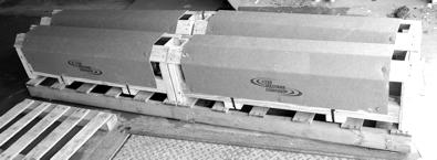
6 GAS MASTRRR Series 32 Storage Requirements The following storage guidelines are provided to ensure safe CIU operation following a storage period. These guidelines should be followed to assure proper CIU performance and warranty consideration should problems occur. Storage of equipment does not extend THE MASTRRR COMPANY S standard warranty period. These guidelines are related to the storage of the series 32 submersible CIU. GENERAL STORAGE PROCEDURES Store CIU in a dry location. Storage temperatures should be within minimum 50 degree F and maximum 150 degree F with relative humidity not to exceed 60%. Store CIU on a pallet or shelf in horizontal position. Do not place CIU s on floor or ground where moisture may build up on box, crate or motor. PERIODIC INSPECTION PROCEDURES Periodic CIU inspection should be made (at least every 3 months) to assure CIU is dry. Inspect to see if any oil has leaked from mechanical seals. Rotate the distributor by hand at least 10 to 15 full revolutions to exercise and lubricate seals faces and bearings. Units stored for more than one full year should be submerged and run once during that period if possible to exercise the motor. Always submerge the CIU completely when running. Run for 30 to 60 minutes submerged Check oil level yearly and/or any time a unit is to be installed or ran. START UP Start up procedures for stored CIU s are the same as described in the start up section of this manual. Follow all procedures for safety and proper operation of the CIU. Start up checks should include: visual inspection of power cord for abrasions, oil level, megger readings of motor before wiring to the starter or CIU control panel, and rotation of distributor by hand before running. For meg ohm readings information refer to the troubleshooting section of this manual. 3
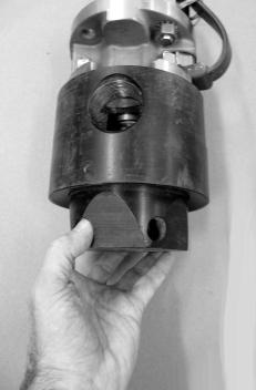
7 GAS MASTRRR Series 32 General Description of Equipment DESCRIPTION OF CIU OPERATION The GAS MASTRRR series 32 submersible chemical flash mixer is a vacuum style induction mixer designed for gas or liquid chemical applications where vacuum is required to induct the chemical. When the CIU is submerged and the motor is running the rotating distributor creates a strong vacuum and pulls the chemical from the source and then flash mixes the chemical in the water stream. The series 32 utilizes a USA manufactured FRANKLIN ELECTRIC submersible 316 S.S. down well motor. The motor operates at 3450 RPM. The motor is liquid filled (USP Mineral oil) and water-cooled. The radial mixing intensity is produced by a rotating vacuum cavity distributor made of UHMW Polyethylene. The chemical is metered by a rotameter for gas chemicals. SUBMERSIBLE MOTOR SPECIFICATIONS The CIU operates at 3450 RPM. The motors are 460 VAC, 3 Phase dedicated voltage. Only 460 VAC power can be supplied. The motor voltage is etched into the S.S. motor barrel. Always check motor voltage etched into S.S. motor barrel before installation or submergence and verify match with supply voltage. See illustration below for etched nameplate data location on motor barrel. Never run the CIU on voltage different than that which is etched into the S.S. motor barrel. The CIU may safely operate at + or 8% of nameplate rated voltage. Consult factory if voltage is not within voltage range. The CIU must be submerged to operate or motor and unit damage will occur. Name Plate Data Location 4
8 GAS MASTRRR Series 32 Electrical Requirements ELECTRICAL REQUIREMENTS If the series 32 CIU is not supplied with a SAVVY control panel please read these requirements carefully. The GAS MASTRRR series 32 has been supplied with a three-phase motor. The unit must be installed with a properly sized combination starter with mechanical or adjustable overload quick trip heater for motor protection. Units no installed with properly sized starters or overload quick trip protection will void CIU warranty. OVERLOAD PROTECTION OF THREE PHASE SUBMERSIBLE MOTORS The characters of submersible motors are different from standard motors and special overload protection is required. If the motor is stalled, the overload protector must trip within approximately 10 seconds to protect the motor windings. The installer must use a lightning surge arrester, SYMCOM monitor and the quick trip protection shown in this table. All recommended overload selections are of the ambient compensated type to maintain protection at high and low air temperatures. All heaters and amp settings shown are based on total line amps. The table below lists the correct selection and settings for several manufacturers. Approval of other types may be requested. Nema Heaters For Overload Relays Adjustable Relays HP Volts Starter Size Furnas A.B. G.E. Set Max (Note 1) (Note 2) (Note 3) (Note 4) K37 K36 K26 J21 J19 J12 L618A L561A L282A K50 K49 K33 J26 J25 J18 L111B L910A L463A K61 K60 K49 J33 J32 J25 L220B L199B L910B K61 K60 K49 J33 J32 J25 L220B L199B L910B Units not installed with properly sized starters or overload quick trip protection will void CIU warranty. 5
9 GAS MASTRRR Series 32 Electrical Requirements Nema Heaters For Overload Relays Adjustable Relays HP Volts Starter Size Furnas A.B. G.E. Set Max (Note 1) (Note 2) (Note 3) (Note 4) K67 K64 K54 J38 J36 J29 L322B L293B L147B (1) 2 (1) 1 K72 K70 K58 J40 J38 J32 L426B L390B L181B (1) 2 2 (1) K76 K75 K64 J43 J42 J35 L650B L520B L265B K78 K78 K69 J45 J44 J38 L787B L710B L352B Units not installed with properly sized starters or overload quick trip protection will void CIU warranty. NOTE FOR OVERLOAD PROTECTION TABLE Footnotes: Note 1: Furnas intermediate sizes between Nema starter sizes apply where (1) is shown in tables; size 1-3/4 replacing 2, 2-1/2 replacing 3. Heaters were selected from Catalog 294, Table 332 and Table 632 (starter size 00, size B). Overload relay adjustments should be set no higher than 100% unless necessary to stop nuisance tripping with measured amps in all lines below nameplate maximum. Note 2: Allen-Bradley heaters were selected from Catalog IC-110. Table 162 (through starter size 4). Bulletin 505, 509, 540 and 570 use these heater tables. Note 3: General Electric heaters are type CR123 usable only on type CR124 overload relays and were selected from Catalog GEP- 126OJ, page 184. Adjustment should be no higher than 100%, unless necessary to stop nuisance tripping with measured amps in all lines below nameplate maximum. Note 4: Adjustable overload relay amp settings apply to approved types listed. Relay adjustment should be set at the specified SET amps. Only if tripping occurs with amps in all lines measured to be within nameplate maximum amps should the setting be increased, not to exceed the MAX value shown. Note 5: Heaters shown for ratings requiring NEMA size 5 or 6 starters are all used with current transformers per manufacturer standards. Adjustable relays may or may not use current transformers depending on design. APPROVED ADJUSTABLE OVERLOAD RELAYS AEG Series: B17S, B27S, B27-2 Sprecher and Schuh Types: CT, CT1, CTA 1, CT3K, CT3-12 thru CT3-42, KTA3, CEF1 set at 8 seconds max. ABB Type: RVH40, RVH65, RVP 160, T25DU, T25CT Siemans Types: 3UA50, -52, -54, , -60, -61, -62, -68, -70, 3VU13, 3VE. Allen Bradley: Bulletin 193, SMP-Class 10 only. Square d/telemecanique Class 9065 Types: TD, TE, TF, TG, TJ, TK, TR, and TJE, or LR1-D, LR1-F, LR2-D13, -D23, -D33. TYPES 18A, 32A, SS-CLASS 10, SR-CLASS 10 and 63A-LB1 Series. Intergral 18, 32, 63, GV2-L, GV2-M, GV2-P, GV3-M. Cutler Hammer: C316F, C316P, C316S, C310-set at 6 seconds max Toshiba Types: 2E RC820, set at 8 seconds max. Fanal Types: K7 or K7D through K400. Westinghouse Types: FT13, FT23, FT33, FT43, K7D, K27D, K67D & MOR Fuju Types: TR-OQ, TR-OQH, TR-2NQ, TR-3 NQ, TR-4NQ, TR6NQ, RCA CQ, 1CQH. Westmaster: OLWROO and OLWTOO suffix D thru P. Furnas Types: US15 48AG, & 48BG, ESP 100-Class 10 only. General Electric: CR4G, CR7G, RT*1, RT*2, RT*4, CR324X- Class only. Klockner-Moeller Types: Z00, Z1, Z4 PKZM1, PKZM3, & PKZ2 LOVATO: RC0, RC22, RC80, RF9, RF25 & RF95 Asco-Delta Types: DQ, LR1-D, LR1-F & LR2-D13, -D23-, -D33. Other relay types from these and other manufacturers may or may not provide acceptable protection. They should not be used without approval of THE MASTRRR COMPANY. 6
10 GAS MASTRRR Series 32 Electrical Requirements TRANSFORMER CAPACITY REQUIRED FOR SUBMERSIBLE MOTORS Distributor transformers must be adequately sized to satisfy the KVA requirements of the submersible motor. When transformers are too small to supply the load there is a reduction in voltage to the motor. The following Table references the motor HP rating, total effective KVA required, and the smallest transformer required for open or closed three phase systems. Open systems require larger transformers since only two transformers are used. Other loads would add directly to the KVA sizing requirements of the transformer bank. Smallest KVA Rating Each Transformer Total Effective Open WYE or DELTA Closed WYE or DELTA Motor HP KVA Required 2 Transformers 3 Transformers POWER FACTOR CORRECTION In some installations, power supply limitations make it necessary or desirable to increase the power factor of the series 32. The following table list the capacitive KVAR required to increase the power factor of large series 32 submersible motors to the approximate values shown at maximum input loading. Capacitors must be connected on the line side of the overload relay, or the overload protection will be lost. Required KVAR for P.F. of: Motor HP Hertz Motor P.F
11 GAS MASTRRR Series 32 Electrical Requirements USE OF ENGINE DRIVEN GENERATORS The following table lists recommended generator sizes, based on typical 80 C rise continuous duty generators, with 35% maximum voltage dip during starting, for specific series 32 motors. This table is conservative and it is recommended the generator manufacturer be consulted whenever possible, especially on larger sizes. There are two types of generators available, externally and internally regulated. They use an external mounted voltage regulator that senses the output voltage. As the voltage dips at motor start up, the regulator increases the output voltage of the generator. Internally regulated generators have an extra winding in the generator stator and are also self excited. The extra winding senses the output current to automatically increase the output voltage. Generators must be sized to deliver at least 65% of the rated voltage during motor starting to ensure adequate motor starting torque. Besides sizing, generator frequency is all important as the motor speed varies with the frequency (HZ). Due to pump affinity laws a pump running at 1 to 2 HZ below motor nameplate frequency design will not meet its performance curve. Conversely, a pump running at 1 to 2 HZ above may trip overloads. Generator Operation. Always start the generator before the motor is started, and always stop the motor before the generator is shut down. The motor thrust bearing may be damaged when generators are allowed to coast down with the motor connected. This same condition occurs when generators are allowed to run out of fuel. Follow generator manufacturer s recommendations for derating at a higher elevation or using natural gas. WARNING: To prevent accidental electrocution, automatic or manual transfer switches must be used anytime a generator is used as standby or back up on power lines. Contact power company for use and approval. ENGINE DRIVEN GENERATORS Minimum Rating of Generator Motor HP Externally Regulated Internally Regulated KW KVA KW KVA
12 GAS MASTRRR Series 32 Electrical Requirements PHASE CONVERTERS Warning! The warranty on all series 32 3-phase submersible motors is void if operated from single phase through a phase converter unless approval of the system (in writing) has been obtained from THE MASTRRR COMPANY. There are a number of types of phase converters available. Each is intended to allow the use of three phase motors on a single-phase power line. Some of these designs present problems, which can lead to motor failure. Phase converters, with the exception of solid-state models, create a manufactured voltage leg by the use capacitors, winding taps or adjustable relays. In all of these arrangements, the voltage balance is critical to the current balance. Some phase converters may be well balanced at one point on the system-operating curve. Submersible CIU systems often operate at differing points on the curve as water levels and chemical federates fluctuate. Other converters may be well balanced at varying loads, but their output may vary widely with fluctuations in the input voltage. The following guidelines have been established for submersible installations to be warrantable when used with a phase converter. 1. Limit pump loading to rated horsepower. Do not load into motor service factor. 2. Maintain at least three feet per second motor cooling. 3. Use time delay fuses or circuit breakers in pump panel. Standard fuses or circuit breakers do not provide secondary motor protection. 4. Current unbalance must not exceed 10% under varying load conditions. 5. SYMCOM will not work with electronic solid-state phase converters. REDUCED VOLTAGE STARTERS All series 32 three phase submersible motors are suitable for full voltage starting. Under this condition the motor speed goes to full speed within one half second or less. The load current goes form zero to locked rotor amps, about 5 to 7 times running amps, and drops to running amps at full speed. This may dim lights, cause momentary voltage dips to other electrical equipment and shock load power distribution transformers. Power companies often require soft starts or limit motor KVA load that may be started directly on line. There are also times when it may be desirable to reduce motor torque. This lessons the stress on shafts, couplings, and castings as well as the supporting discharge piping. A strong voltage supply and very little cable voltage drop produces high starting torque. In other words, this is an installation that is electrically and mechanically stiff. Reduced voltage starters are often used to reduce starting KVA or torque, and sometimes to slow the immediate acceleration of the water on start up to control up thrust and waterhammer. 9
13 GAS MASTRRR Series 32 Electrical Requirements REDUCED VOLTAGE STARTERS Continued With maximum recommended cable length where there is a 5% voltage drop in the cable, there will be about 20% reduced starting current and about 36% reduced starting torque compared to having rated voltage a the motor. On some installations this may be enough reduction in starting current so that reduced voltage starters may not be required. Standard three phase motors have line leads so only resistance, autotransformers, or solid-state reduced voltage starters may be used. The autotransformer type is preferred over resistance and solid state types because it draws lower line current for the same starting torque. When reduced voltage starters are used it is recommended the motor be supplied with at least 55% of rated voltage to ensure adequate starting torque. Most autotransformer starters have 65% and 85% taps. Setting the taps on these starters depends on the percentage of the maximum allowable cable length used in the system. If the cable length is less than 50% of the maximum allowable, either the 65% or 80% taps maybe used. When the cable length is more than 50% of the allowable, the 80% tap should be used. Solid state reduced voltage starters may be used with submersibles, but may not be usable with SYMCOM monitors. Consult the factory. Both electromechanical and solid state starters have adjustable time delays for starting. Typically they are preset at 30 seconds. They must be set so the motor is at full voltage within two to three seconds maximum to prevent overload trip and unnecessary motor heating. Open transition starters, which momentarily interrupt power during the starting cycle, are not recommended. Should the motor/pump rotating parts be passed through their critical speed, as low is removed and high voltage applied, the resulting stresses can break shafts and couplings. Only closed transition starters, which have no interruption of power during the starting cycle, should be used. VARIABLE FREQUENCY DRIVES Series 32 three phase motors are operable from variable frequency inverter drives when applied within guidelines specified below. These guidelines are based on present MASTRRR COMPANY information for inverter drives, lab tests and actual installations, and must be followed for warranty to apply to inverter drive installations. 1. Variable speed drives should be variable frequency, constant volts per Hertz type, and may have sine wave, pulse width modulated (PWM) or six-step wave shape. The base voltage should be nameplate voltage and frequency of the motor. 2. Over current protection in the inverter or separately furnished must trip within 10 seconds at 5 times motor maximum nameplate amps in any line, and ultimately trip 115% of motor maximum nameplate amps in any line. 10
14 GAS MASTRRR Series 32 Electrical Requirements VARIABLE FREQUENCY DRIVES Continued 3. Any application below 30 Hertz or above 80 Hertz must be specifically approved by THE MASTRRR COMPANY. Operation at lower frequency can cause motor bearing failure, and higher frequency can raise internal hydraulic losses to an unacceptable level. If startup or shutdown frequency is ramped, the time that power is below 30 Hertz should not exceed 1 second. 4. Pump load must be selected so motor maximum nameplate amps are not exceeded under all running conditions. 5. MASTRRR COMPANY specified water temperature and flow past the motor must be maintained at speeds which the load the motor up to maximum nameplate amps. At reduced speeds and loading, cooling flow must be adequate to maintain equivalent motor temperature. 6. Variable speed drive electronic circuits plus the inductance of the motor generally create significant levels of voltage spikes on the motor supply lines. For normal motor life expectancy, the maximum amplitude of these repetitive spikes measured from zero should not exceed 1500 volts. 7. SYMCOM motor monitoring systems are not usable on inverter driven installations because the non-sinusolidal wave shape from the inverter prevents proper SYMCOM operation. The wave shape also reduced motor efficiency, typically about two percentage points. 8. To confirm whether an installation or system is acceptable and warrantable, full details of the inverter drive should be submitted to THE MASTRRR COMPANY. 11

15 GAS MASTRRR Series 32 Electrical Requirements THREE PHASE POWER UNBALANCE A full three-phase supply is recommended for all three-phase motors, consisting of three individual transformers or one three-phase transformer. So-called open delta or wye connections using only two transformers can be used, but are more likely to cause problems, such as poor performance overload tripping or early motor failure due to current unbalance. Transformer ratings should be no smaller than listed in the Transformer Capacity table located on page 7 for supply power to the motor alone. SYMCOM VOLTAGE AN MOTOR AMPERAGE MONITOR/CONTROLLER INSTALLATION The series 32 CIU is required to operate with a SYMCOM 777-TS 3 phase voltage and motor amperage monitor. CIU s installed without a SYMCOM 777-TS or factory approved monitor and a DELTA or Joslyn lightening surge arrester will not be covered by warranty. 12
 will enter at the bottom right of the NEMA 4X enclosure and terminate at the top of the disconnect switch located in the upper right side of the enclosure.")
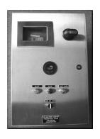
16 GAS MASTRRR Series 32P Electrical Requirements SAVVY PANEL CONNECTIONS Conduit knock out holes are provided in the SAVVY control panel enclosure for power supply wires, control wiring and motor lead cable. The power supply wires (qty. 4) will enter at the bottom right of the NEMA 4X enclosure and terminate at the top of the disconnect switch located in the upper right side of the enclosure. The submersible motor power cord will enter the bottom center of the enclosure and terminate at the bottom of the starter located in the lower right side of the enclosure. The control wires and remote indication wiring enter and terminate at the bottom left of the enclosure. TERMINAL BLOCK DESCRIPTIONS (GENERAL INPUT/OUTPUT WIRING) PLACE JUMPER ACROSS #3 & #4 IF REMOTE START/STOP IS NOT REQUIRED. UNIT WILL NOT START WITHOUT # H HOT 120 VAC JUMPER OR REMOTE CLOSURE! # 3 REMOTE CONTACT START/STOP SCADA # 4 REMOTE CONTACT START/STOP SCADA # 14 C REMOTE INDICATION UNIT ON/OFF DRY CONTACT # 15 NO REMOTE INDICATION UNIT ON/OFF DRY CONTACT # 16 NC REMOTE INDICATION UNIT ON/OFF DRY CONTACT # 17 DRY CONTACT FOR FAULT ALARM # 18 DRY CONTACT FOR FAULT ALARM CONTROL WIRING CIU POWER CABLE 3 PHASE POWER INCOMING 13

17 GAS MASTRRR Series 32 Operational Procedures PRE-START UP CHECKS The series 32 unit should be checked for proper mounting location and orientation per the engineer s specifications. *Check that all cables or materials are clear from the distributor area of the unit. *Check that all bolts are tight and that the unit is securely in place. *Check that the flexible hose and fittings are clamped and fastened securely. *Check all lugs for tightness. *Check supply voltage with meter for correct motor voltage. Voltage etched on motor should match the measured voltage. Note voltage should not exceed + or - 8% of rated motor voltage. *Check that fuses are rated for full load amps of motor. (Full load amps etched on motor shell). *Check that the SYMCOM components are in place and wired correctly. SAFETY PROCEDURES WARNING! Caution should always be used when working with AC power! Only certified electrical personnel should connect and check all connections. Always check that power is disconnected before work is done within the control enclosures. Always check with voltage meter! Never assume the disconnect is off! START UP PROCEDURES The series 32 is a liquid filled (USP Mineral oil) motor. Check liquid level in the upper housing for Mineral oil level. 14
18 GAS MASTRRR Series 32 Operational Procedures PRE-START UP CHECKS - PLUMBING The series 32 unit may be supplied with a flexible PVC wire reinforced flex hose for ease in raising and lowering the unit. Plumbing and all valves should be checked for proper mounting location and orientation. To assure correct operation and safety, proper installation of piping, valves, and connections must be achieved. 15
19 GAS MASTRRR Series 32 Operational Procedures NORMAL START-UP 1. Check all electrical connections for proper installation and tightness. 2. See page 19 for calibration procedures on the SYMCOM 777-TS motor monitor. 3. Check to insure proper rotation of mixing distributor. See page 18 for rotation check procedures. Rotation should be counter-clockwise when looking at the face of the mixing distributor or clockwise when looking at the top of the motor. See page 18 for reversing motor rotation. 4. Check to see if flex hose is connected to the GAS MASTRRR unit and the second feed port has a cap plug installed (second feed port not installed on all units). Lower unit to proper submergence depth. Connect flex hose to the chemical source piping connection. Close shut-off valve at the chemical source piping connection. Disconnect flex hose at the shut off valve. 5. Make sure unit is fully submerged and start GAS MASTRRR. 6. Check flex hose for vacuum. For liquid feed applications a non-vacuum style unit may be supplied. After flex hose is connected, the unit will continue to pull vacuum until stabilized. 7. Adjust feed rate at the chemical feed source. WARNING! Always turn unit off and shut off disconnect switch before raising unit above the water surface. Never run unit out of water. NORMAL SHUT DOWN 1. Close shut-off valve at the chemical source piping and let the unit run. Disconnect flex hose and let the unit run to evacuate remaining chemical in the flex hose. 2. After chemical evacuation is accomplished turn HOA switch to off position and disconnect power via the disconnect lever located on the SAVVY panel. 16
20 GAS MASTRRR Series 32 Operational Procedures Warning! Always lower the unit completely below the water surface. Never run unit out of water. EMERGENCY START-UP 1. Lower unit completely below the water surface or check that the unit is submerged. 2. Verify HOA is in OFF position. Turn disconnect switch off and open panel door. Turn disconnect switch shaft with wrench to on. Program model 777-TS with instructions from page Turn the HOA switch to on and run unit. 4. Check for operation of the chemical feed equipment and adjust to proper feed range. 5. After chemical operation is accomplished and verified the complete start-up procedure should be performed at the earliest possible time. Warning! Always turn unit off and shut off disconnect switch before raising unit above the water surface. Never run unit out of water. EMERGENCY SHUT DOWN 1. Close shut-off valve at the chemical source piping. 2. Turn the GAS MASTRRR to the off position at the HOA and/ turn power off via the disconnect lever on the SAVVY panel. 17

21 GAS MASTRRR Series 32 Operational Procedures CHECKING AND CORRECTING ROTATION NEVER HOLD OR TOUCH THE DISTRIBUTOR WHILE CHECKING ROTATION! STAND CLEAR OF UNIT WHEN CHECKING ROTATION! NEVER RUN UNIT DRY! The series 32 CIU distributor runs in a CCW direction when looking at the distributor face. When checking rotation, bump starter momentarily (1 or 2 seconds only) with unit out of water if required. Never run unit out of water more than a few seconds! Run unit only in the direction indicated above. REVERSING MOTOR ROTATION Always turn power off and disconnect power at disconnect switch! Check power with voltage meter to verify power is off. Then rotate any two (2) motor legs (example rotate L1 and L2 motor lead wires). Verify rotation change. Always check voltage on all legs to ground and leg to leg. Amperage on all (3) legs. Note and log all readings for warranty registration. Verify trip heaters are sized or adjusted at full load amps of the motor. FL amps are etched on motor barrel. Record all readings on the start up test report located at the end of this manual. 18
22 GAS MASTRRR Series 32 SymCom Calibration Procedures WARNING! Always lower the unit completely below the water surface. Never run unit out of water. Verify HOA is in the OFF position. Turn power disconnect switch to ON to program the SymCom 777-LR unit with the motor turned (HOA) OFF. Calibration programming of SymCom 777-LR Verify the number of loops each leg of power cable makes through each amp ring hole (holes are marked A, B, & C on the SymCom 777-LR monitor (the rectangular holes behind the holes marked A, B, & C are provided for wire looping). The following chart gives the number of loops required for the Full Load Amps of the motor. Full Load Amps # of Loops # of Conductors through A,B, & C MULT to Program SymCom 777-LR Programming 1. Select the feature to program by rotating the MODE SELECT switch to the desired position. The MULTI setting must be programmed before any of the current settings to ensure proper display of actual current set points. Therefore, SymCom recommends programming the LV setting first, then move clockwise through the positions to complete the process. 2. Push and hold the RESET / PROGRAM button. 3. Rotate the DISPLAY / PROGRAM adjustment to the desired setting of the feature as shown in the LED display. 4. Release the RESET / PROGRAM button. The model 777-LR is programmed when the button is released. 5. Continue step 1-4 until all features are programmed. See notes and suggested settings on page
 OFF.")
23 GAS MASTRRR Series 32 SymCom Calibration Procedures WARNING! Always lower the unit completely below the water surface. Never run unit out of water. Verify HOA is in the OFF position. Turn power disconnect switch to ON to program the SymCom 777-LR unit with the motor turned (HOA) OFF. SETTINGS FOR THE SYMCOM 777-LR MOTOR SAVER RECOMMENDED SETTINGS FOR THE GAS MASTRRR SERIES 32, 5 HP, 460vac PARAMETERS SETTINGS LV 425 HV 500 VUB 005 MULT 1 OC 8.0 UC 5.0 CUB 005 TC 005 RD RD RD #RU/ADDR 001/AO1 #RF oc1 UCTD 002 GF 0.80 Set Combination Starter Trip Over Load Setting to 8.0 amps. 19A
24 GAS MASTRRR Series 32 SymCom Calibration Procedures WARNING! Always lower the unit completely below the water surface. Never run unit out of water. Verify HOA is in the OFF position. Turn power disconnect switch to ON to program the SymCom 777-LR unit with the motor turned (HOA) OFF. Continued from page 19. Calibration programming of SymCom 777-LR Note: Some MODE SELECT positions are dual function such as #RU / ADDR position. When the MODE SELECT switch is pointed at the #RU / ADDR, you may view and program #RU and ADDR. To view the two settings rotate the DISPLAY / PROGRAM adjustment across its entire range. You will see the #RU setting when the DISPLAY / PROGRAM adjustment is between approximately 7 O Clock and 11 O Clock. You will see the ADDR setting when the DISPLAY / PROGRAM adjustment is between approximately 11 O Clock and 5 O Clock. To program #RU or ADDR, following the programming instructions above. The #RU setting will only be programmed when the DISPLAY / PROGRAM adjustment is between approximately 7 O Clock and 11 O Clock. Likewise, the ADDR setting will only be programmed when the DISPLAY / PROGRAM adjustment is between the 11 O Clock and 5 O Clock. ADDR setting should be A 1. Suggested Settings LV / HV The recommended settings for LV (low voltage) and HV (high voltage) are determined by the original motor manufacturer. Settings are to be no more than + 8% of the motors name plate voltage. Series 32 submersible motors are nameplate rated at 200, 230, or 460 VAC. Therefore settings are as follows: 200 VAC motors LV = 184 & HV = VAC motors LV = 211 & HV = VAC motors LV = 423 & HV = 496 VUB VUB is the voltage unbalance trip point. The Nema MG1 standard recommends against operating a motor above a 5% voltage unbalance under any circumstances. Therefore, a setting of 5 is the highest setting allowed. MULT MULT is the multiplication factor for determining true current settings and represents the number of conductors passing through the main current holes marked A, B, & C on the 777-LR. See page 20 to determine MULT number or count the number of conductors passing through each hole. OC Represents the manufacturer s maximum service factor amperage. The OC (over current) setting is typically no more than 95% of S.F. FLA (full load amperage). See page 23 & 24 for motor nameplate data. Example a 5 HP, 460 VAC motor has a 8.8 S.F. FLA rating. The OC setting should not exceed 8.0 amps. UC The UC (undercurrent) setting is typically set at 80% of FLA (full load amperage). This setting will typically detect if a submersible or inline unit is running out of water. 20
25 GAS MASTRRR Series 32 SymCom Calibration Procedures WARNING! Always lower the unit completely below the water surface. Never run unit out of water. Verify HOA is in the OFF position. Turn power disconnect switch to ON to program the SymCom 777-LR unit with the motor turned (HOA) OFF. Continued from page 20. Calibration programming of SymCom 777-LR Suggested Settings CUB CUB is the current unbalance trip point. This setting must be no more than 5%. A setting of 5 or lower is advised. TC TC designates the trip class for overload protection. The trip class defines the trip delay when an overload is detected. Series 32 submersible units require a TC setting of 010 or lower. Set at 005. RD1 RD1 is the rapid cycle timer. An RD1 setting 20 seconds will generally protect the motor from rapid successive power outages or short cycling caused by the motor controls. Set at 000. RD2 - RD2 is the restart delay after the overload relay trips on current unbalance, single phasing and overload. A setting of 1 5 minutes is recommended. SET at 002. RD3 RD3 is the restart delay after an undercurrent trip. A setting of 1-5 minutes is recommended. SET at 002. #RU #RU is the number of successive restart attempts allowed after an undercurrent fault before the underload relay requires manual reset. A setting of 1 is recommended. SET at 001. ADDR ADDR is the address setting for the RS485 communication to the RM2000 keypad display. This setting should be A01 and should not be adjusted. SET at AO1. #RF #RF is the number of successive restart attempts allowed after a current unbalance, single phasing or overload fault. The recommended setting is oc2 which will allow 2 restart attempts on over current then require manual reset. This setting should be oc1 and should not be adjusted. SET at oc1. UCTD UCTD is the undercurrent trip delay timer. This setting represents the maximum time that the model 777 will tolerate an undercurrent condition. This setting should be 2 4 seconds and should not be adjusted above 4 seconds. SET at 002 GF GF is the ground fault protection amperage threshold. This setting detects the leakage current to ground and signals an insulation breakdown in the system. The GF setting should be somewhere between 10 and 20% of the full load amperage for the HP installed. MODE / SELECT switch should be placed in the run position after parameters are programmed. 21
26 GAS MASTRRR Series 32 SymCom Calibration Procedures WARNING! Always lower the unit completely below the water surface. Never run unit out of water. Verify HOA is in the OFF position. Turn power disconnect switch to ON to program the SymCom 777-LR unit with the motor turned (HOA) OFF. Continued from page 21. Calibration programming of SymCom 777-TS The LED output display on the model 777-LR can show various system operating parameters: * Average Voltage * Average Current * L1 L2 Voltage * L1 Current (A) * L2 L3 Voltage * L2 Current (B) * L3 L1 Voltage *L3 Current (C) When the MODE SELECT switch is in the RUN position, the LED will display one of the above operating parameters. To select or change the display parameter, turn the DISPLAY / PROGRAM adjustment to the desired position as shown on its label. The multifunction display also announces system faults such as low voltage, high voltage, single phasing, voltage unbalance, current unbalance, and reverse phasing errors. Any time the MODE SELECT switch is in the RUN position, the RESET / PROGRAM button may be pushed to view the last fault which occurred. The table below shows the possible messages. Displayed Message oc SP ub uc CF GrF HI Lo rp off Meaning Tripped on Over current Tripped on Current Single Phasing Tripped on Current Unbalance Tripped on Undercurrent Tripped on Contactor Failure Tripped on Ground Fault Tripped on High Voltage Tripped on Low Voltage Incoming phases have been reversed. A stop command was issued from a remote source. 22
27 GAS MASTRRR Series 32 Operational Procedures SERIES 32 ELECTRICAL MOTOR SPECIFICATIONS Name Plate Data 2 HP VOLTS PHASE HZ RPM INSULATION S.F. FULL LOAD AMPS S.F. FULL LOAD AMPS CLASS F CLASS F CLASS F VOLTS LOCKED ROTOR AMPS POWER FACTOR % EFFICIENCY % BREAKER OR FUSE AMPS S.F. F.L. 3/4 S.F. F.L. 3/4 KVA CODE STD. DELAY L L L HP VOLTS PHASE HZ RPM INSULATION S.F. FULL LOAD AMPS S.F. FULL LOAD AMPS CLASS F CLASS F CLASS F VOLTS LOCKED ROTOR POWER FACTOR % EFFICIENCY % BREAKER OR FUSE AMPS AMPS S.F. F.L. 3/4 S.F. F.L. 3/4 KVA CODE STD. DELAY H H H HP VOLTS PHASE HZ RPM INSULATION S.F. FULL LOAD AMPS S.F. FULL LOAD AMPS CLASS F CLASS F CLASS F VOLTS LOCKED ROTOR POWER FACTOR % EFFICIENCY % BREAKER OR FUSE AMPS AMPS S.F. F.L. 3/4 S.F. F.L. 3/4 KVA CODE STD. DELAY H H H

28 GAS MASTRRR Series 32 Operational Procedures SERIES 32 ELECTRICAL MOTOR SPECIFICATIONS Name Plate Data 7.5 HP VOLTS PHASE HZ RPM INSULATION S.F. FULL LOAD AMPS S.F. FULL LOAD AMPS CLASS F CLASS F CLASS F VOLTS LOCKED ROTOR POWER FACTOR % EFFICIENCY % BREAKER OR FUSE AMPS AMPS S.F. F.L. 3/4 S.F. F.L. 3/4 KVA CODE STD. DELAY H H H HP VOLTS PHASE HZ RPM INSULATION S.F. FULL LOAD AMPS S.F. FULL LOAD AMPS CLASS F CLASS F CLASS F VOLTS LOCKED ROTOR POWER FACTOR % EFFICIENCY % BREAKER OR FUSE AMPS AMPS S.F. F.L. 3/4 S.F. F.L. 3/4 KVA CODE STD. DELAY H H H HP VOLTS PHASE HZ RPM INSULATION S.F. FULL LOAD AMPS S.F. FULL LOAD AMPS CLASS F CLASS F CLASS F VOLTS LOCKED ROTOR POWER FACTOR % EFFICIENCY % BREAKER OR FUSE AMPS AMPS S.F. F.L. 3/4 S.F. F.L. 3/4 KVA CODE STD. DELAY H H H HP VOLTS PHASE HZ RPM INSULATION S.F. FULL LOAD AMPS S.F. FULL LOAD AMPS CLASS F CLASS F CLASS F VOLTS LOCKED ROTOR POWER FACTOR % EFFICIENCY % BREAKER OR FUSE AMPS AMPS S.F. F.L. 3/4 S.F. F.L. 3/4 KVA CODE STD. DELAY J J J
29 GAS MASTRRR Series 32 Operational Procedures CHECKING AND CORRECTING THREE PHASE POWER UNBALANCE A full three-phase supply is recommended for all three-phase motors, consisting of three individual transformers or one three-phase transformer. So-called open delta or wye connections using only two transformers can be used, but are more likely to cause problems, such as poor performance overload tripping or early motor failure due to current unbalance. Transformer ratings should be no smaller than listed in the Transformer Capacity table located on page 7 for supply power to the motor alone. After correct rotation has been established, check the current in each of the three motor leads. Use the RM-2000 keypad. In real-time mode select display to show amperage on each leg (log amp readings.) Scroll till the current unbalance % and voltage unbalance % display appears as below. CURR. UNBALANCE = 2% VOLT. UNBALANCE = 1% If the current unbalance is 2% or less, leave the leads as connected. If current unbalance is more than 2%, current readings should be checked on each leg using each of the three possible hook-ups. Roll the motor leads across the starter in the same direction to prevent motor reversal. Always shut off disconnect power switch for safety! Starter Terminals Hook 1 Hook 2 Hook 3 L1 L2 L3 L1 L2 L3 L1 L2 L3 T1 T2 T3 T1 T2 T3 T1 T2 T3 Motor leads R B W W R B B W R Current unbalance should not exceed 5% at service factor load or 10% at rated input load. If unbalance cannot be corrected by rolling leads, the source of the unbalance must be located and corrected. If, on the three possible hookups, the leg farthest from average stays on the same power lead, most of the unbalance is coming from the power source. However, if the reading farthest from average moves with the same motor lead, the primary source of unbalance is on the motor side of the starter. In this instance, consider a poor lug connection or damaged power cable. 25

30 2 26
31 GAS MASTRRR Series 32 Operational Procedures NORMAL OPERATION In normal operation the control panel HOA switch should be in (A) automatic. The series 32 unit will start and run continuous unless stopped manually or a fault condition occurs. The unit should always be submerged and never allowed to run out of water. The unit will pull a strong vacuum and the gas chemical will be controlled from an external pacing valve. The amperage will drop as the gas feed increases. The series 32 unit should run below rated full load amps at full vacuum (zero gas feed). For liquid feed applications the chemical will be controlled from an external chemical metering pump. The amperage will increase slightly as the liquid chemical feed rate increases. The voltage/amperage monitor will look at motor amperage and line voltage for fault conditions. The unit monitors and will shut down for the following fault conditions: low amperage, high amperage, low voltage, high voltage, amperage unbalance, phase loss, phase reversal, ground fault, high stator temperature, and rapid cycling. Should a fault occur (high amperage as example) the unit will immediately stop and a 1- minute time delay will count and then restart the unit. This allows fault condition to clear if it was an intermittent problem. The unit will restart after the time out period. Should the unit continue to see the high amperage condition, it will again stop and a second 1 minute time delay restart will commence. Should the fault condition not clear itself by the second restart, the unit will stop and the fault condition will be displayed. The unit will then require manual reset to start. Intermittent voltage supply problems may cause nuisance trips, which the time delay feature may save the unit from damage and then restart after the condition clears itself. The unit has time delay reaction to low amperage; the time delay interval is 1 minute. The unit will try to restart one time. Should the unit continue to see low amperage condition, it will stop and require manual reset to start. The unit has an instantaneous trip for voltage faults and will not restart until proper power is restored. The series 32 unit may be momentarily run in hand position to check/verify distributor rotation. A combination starter with trip heaters should be installed as a minimum amount of protection. THE MASTRRR COMPANY WILL NOT WARRANTY UNITS THAT DO NOT HAVE AT A MINIMUM A COMBINATION STARTER WITH PROPERLY SIZED TRIP HEATERS. The warranty is void if the motor monitor is by-passed. Maintenance records are required for inspection when warranty claims are made. 27
32 GAS MASTRRR Series 32 Troubleshooting Procedures GENERAL CONTROL PANEL SYMCOM FAULTS *Note: Before shutting off main power to the control panel or shutting off disconnect switch at the control panel, open door and log fault conditions via fault conditions via fault history mode. Log information. Fault Alarm SP Voltage HI or LO oc uc CF Checking Procedure Using voltmeter check lugs L1, L2, and L3 at the top of the SYMCOM monitor for correct volts on each leg. Check Leg to Leg, & Leg to Grnd. Using voltmeter check lugs L1, L2, and L3 at the top of the combination starter for correct volts on each leg. Check Leg to Leg, & Leg to Grnd. Power must be + or 8% of rated voltage. Using voltmeter check lugs L1, L2, and L3 at the motor power cord leads for correct volts on each leg. Check Leg to Leg, & Leg to Grnd. Power must be + or 8% of rated voltage. Shut off power and raise unit for inspection. Check distributor area for material wedged between cone and distributor. Rotate distributor by hand to see if rotation is free or binding. If free spins then check oil level of motor, and meg motor leads for shorts to ground. See meg test information in this manual. Check to see that unit is fully submerged. Using voltmeter check lugs L1, L2, and L3 at the motor power cord leads for correct volts on each leg. Check Leg to Leg, & Leg to Grnd. Power must be + or 8% of rated voltage. Shut off power and raise unit for inspection. Check distributor area for material wear between cone and distributor. Rotate distributor to see if it free spins on shaft. Check for impact marks on distributor. During severe impact with solid object the internal shaft coupling will act as a shear pin. Contactor Failure Do not try to restart unit. Raise CIU and check power cord for cuts or abrasion. Corrective Action Check for loose lugs back to power source. Contact power company if voltage is incorrect. Contact power company if voltage is incorrect. Contact power company if voltage is incorrect. Clear material if any. If locked and will not turn, contact factory. If no oil, flush motor and refill with oil. If meg test shows short, contact factory. Contact power company if voltage is incorrect. Replace cone and/or distributor. Contact factory. Replace cut or damaged power cord. 28
33 GAS MASTRRR Series 32 Troubleshooting Procedures GENERAL MOTOR FAULTS MOTOR DOES NOT START *Note: Before shutting off main power to the control panel or shutting off disconnect switch at the control panel, open door and verify any faults on RM-2000 monitor. Log fault conditions. Problem Checking Procedure Corrective Action No power or incorrect voltage Fuses blown or circuit breaker tripped Using voltmeter check lugs L1, L2, and L3 at the top of the 777 monitor for correct volts on each leg. Check Leg to Leg, & Leg to Grnd. Check fuses for recommended size and check for loose, dirty or corroded connections in fuse receptacle. Check Check for tripped circuit breaker. If circuit breaker immediately trips on restart shut off power, raise unit and check power cord for cuts or abrasion. Meg motor leads for shorts to ground. See meg test information in this manual. Contact power company if voltage is incorrect. Replace with proper fuse or reset circuit breaker. If meg test shows short, contact factory. Locked Unit Locked rotor conditions can result from material wedged between distributor and cone. Unit ran without oil in motor. Power related problems: voltages, unbalanced, phase loss, or surges swell hermetically sealed stator. Amp readings will be 3 to 6 times higher than normal. Inspect unit and remove material. Contact factory for RGA #. Cut or Bad Power Cord SAVVY Panel or SYMCOM Malfunction Inspect cord for cuts or abrasions. Meg cord to check for shorts or water damage. Meg motor to check for damage. Turn power off and on by shutting off the disconnect switch and then back on. This will reset circuit breaker. Push reset button on the 777- monitor and try to restart unit. Replace power cord with factory cord. Contact factory for cord or if motor is damaged. Contact factory if power or SYMCOM reset fails. 29
34 GAS MASTRRR Series 32 Troubleshooting Procedures GENERAL MOTOR FAULTS RESISTANCE CHECK *Note: Turn HOA off and shut off disconnect switch to avoid damage to meter or electrical shock hazard. Disconnect all motor leads from SAVVY panel or starter. How to Measure Ohm Values Between Leads and Ground (Insulation Resistance) Connect one ohmmeter lead to any one of the motor leads and the other ohmmeter lead to ground. Set the scale lever to R x 100K and zero balance the ohmmeter. What is to be done The Results What It Means Measure resistance from any motor Ohms per table below for line to line If the ohm value is normal, the motor cable lead to ground resistance. >.500 Megohms windings are not grounded and the cable (Insulation resistance) insulation is not damaged. If the ohm value is below normal, either The windings are grounded or the cable Insulation is damaged. Check the cable For cuts or abrasions. How to Measure Resistance between Leads (Winding Resistance) Connect one ohmmeter leads to any two of the motor leads. Set the scale lever to R x 1 for values under 10 ohms. For values over 10 ohms, set the scale lever for R x 10. Zero balance the ohmmeter. What is to be done The Result What It Means Measure winding resistance Ohms per table below for line to line If all ohm values are normal, the motor (Resistance between leads) resistance. Windings are neither shorted nor open. If any one ohm is less than Normal the motor is shorted. If any one ohm value is greater than Normal, the winding or the cable is open, Or there is a poor cable junction or terminal Connection. VOLTS Line to Line Resistance 1 HP 2 HP 3 HP 5 HP 7.5 HP 10 HP 15 HP 25 HP
35 GAS MASTRRR Series 32 Maintenance Procedures QUARTERLY MAINTENANCE ELECTRICAL CHECKS At 3-month intervals or sooner check voltage leg to leg, then legs to ground. Log readings on maintenance inspection form located at the end of this manual. Make copies for future inspection reports. WARNING! Caution should always be used when working with AC power! Only certified electrical personnel should connect and check all connections. Always check that power is disconnected before work is done within the control enclosures. Always check with voltage meter! Never assume disconnect is off! Maintenance records are required for all returned units for warranty consideration. LIQUID OIL LEVEL CHECKS WARNING! Always turn unit off and shut off disconnect switch before raising unit above the water surface. Never run unit out of water. Check unit for liquid oil fill level. See details below. Turn unit off and raise to inspect for material that may have collected around the lower propeller area. Remove the ¼ S.S. liquid fill plug and inspect the mineral oil fill level. Add mineral oil as required. Do not fill to top! Leave a ½ air gap for expansion. Remember to replace ¼ S.S. plug. Check that all cables or materials are clear from the distributor area of the unit. Check that all bolts are tight and the unit is securely in place. Check that the flexible hose and fitting are clamped and fastened securely. Check all lugs for tightness. Check supply voltage with meter for correct motor voltage. Voltage etched on motor should match the measured voltage. Note voltage should not exceed + or 8% of rated motor voltage. REMEMBER TO REINSTALL 1/4" S.S. PLUG 31
36 GAS MASTRRR Series 32 Maintenance Procedures MAINTENANCE PROCEDURES At 3 month intervals. Fill out and log inspections with inspection data sheets located in section 7 of this manual. Maintenance reports copies will be required to be submitted with any warranty claim. Check voltage L1 L2, L2-L3, and L3 L1 Log readings. Check L1-G, L2-G, and L3-G Log readings. Check motor amperage on L1, L2, and L3 Log amperage readings. Turn unit off and raise to inspect for material that may have collected around the lower propeller area. Remove the S.S. liquid fill plug and inspect the liquid fill mineral oil level. The unit should have a mineral oil level with a small air gap (1/2 air gap). Add oil as required. See details on page 31. Inspect power cord for cuts or abrasions. Make sure cord and hose are secured and clear of the rotating propeller when installing or lowering the unit. SPARE PARTS & SUPPLIES The Series 32 motor is a sealed unit and it does not require seals or thrust bearing spare parts to be stocked on the shelf. Check data sheet on Warranty and Exchange Program located in section 7 of this manual for details on the exchange procedures. Supplies should include food grade USP Mineral Oil for quarterly oil level inspection and a voltage/amperage meter to check power and operating amps. Note: the RM2000 display panel can display voltages and amperages in real-time. Mineral oil: Food grade USP shelf stock at most stores Alternate oil: Baby oil MAINTENANCE TOOLS REQUIRED Tools should include: 11/16 box end wrench (for oil plug) Screw drive (to check and tighten power lugs while power is OFF) Voltage/amperage meter: Fluke model 36 or equal (quarterly amperage check) 32
37 GAS MASTRRR Series 32 Maintenance Procedures GENERAL MAINTENANCE GAS MASTRRR Disassembly The GAS MASTRRR series 32 is a sealed unit. The general maintenance or field repair should be limited to removal of the distributor or cone for cleaning of debris, chemical scale buildup, or for upgrades in design. Removal or replacement of power cord assembly during the warranty should only be performed by THE MASTRRR COMPANY or authorized repair representatives unless permission is given in writing. See power cord removal and installation details below. Disassembly of a GAS MASTRRR series 32 motor should only be performed by THE MASTRRR COMPANY or its authorized repair representatives. Motors under warranty should be returned freight prepaid (with maintenance reports) to THE MASTRRR COMPANY for warranty consideration and service. Warning! Sending the motor to a local electric motor repair shop is at the risk of the owner. Any work or disassembly performed on a GAS MASTRRR series 32 during the warranty period by someone other than THE MASTRRR COMPANY or authorized representative, will void any and all warranty in its entirety. Power Cord Removal and Installation Warning! Removal of the power cord assembly during the warranty period is at the risk of the owner. Any work or disassembly performed on a GAS MASTRRR series 32 power cord during the warranty period by someone other than THE MASTRRR COMPANY or authorized representative, will void any and all warranty in its entirety, unless permission is given in writing. Cables damaged while in operation should be replaced with a new power cord assembly. Splicing submersible cables should be made with commercially available potting or heat shrink slicing kits for emergency use only. Notification should be made to THE MASTRRR COMPANY of any power cord damages or repairs. Units sent in for warranty consideration should have the power cord intact. Do not cut the power cord at the motor to reduce weight. Power cords that have been cut off below 10 (feet) will jeopardize warranty consideration. With written permission the power cord assemblies may be removed or replaced in the field. Series 32 submersible power cords seal by tightening the jam nut, which compresses the rubber bushing, insert against the end of the motor stator. Properly assembled power leads are a permanent and reliable seal for submerged duty in water or wastewater applications. Since the rubber bushing insert is tightly compressed and takes shape matching the exact cavity of each individual motor, reusing a power cord after removal from a motor is not recommended. Permanent change in the rubber shape and resulting bushing damage, which occur during removal or re-assembly, make reuse a risk in same or any other motor. The following page describes the proper procedures for removal and installation of power cord assemblies in Series 32 submersible motors. 33

38 GAS MASTRRR Series 32 Maintenance Procedures Removal of the Power Cord Assembly All warnings should be read and understood before removal of the power cord assembly from any GAS MASTRRR series 32 submersible unit. Warnings are listed on page 33. Turn power off to the unit before raising, and disconnect power cord leads from the SAVVY control panel or starter. Loosen the jam nut with a wrench and slide the nut up the cord a few inches. Pull the cord from the stator housing. The cord may be difficult to remove and no tools should (pliers) be used which may damage the cord or potting material within the S.S. outer sleeve. Installation of the Power Cord Assembly All warnings should be read and understood before removal of the power cord assembly from any GAS MASTRRR series 32 motor. Warnings are listed on page 33. Make sure the power cord bushing and the connector hole in the motor stator are clean and dry. A small amount of silicon grease is permissible, but all dirt particles or moisture should be removed. Meg the motor stator windings using a 1,000-volt DC megger. A good motor should measure at least 50 megohms between connector pins in the connector hole and the motor shell. Follow the megger s instructions and log the value after the value stops changing. Make sure the cord assembly is free from damage, dirt or moisture, and that the entire rubber-bushing surface is lightly greased with Dow 7 or equivalent insulative grease. Do not attempt to insert an ungreased cord assembly in the connector hole, which may cause bushing damage or an unreliable seal. When inserting the stainless steel jam nut, pre-lubricate the jam nut threads with Dow 7 or equivalent insulative grease, or nonconductive Teflon thread lubricant to prevent galling. Insert by hand into the connector hole with the rounded key on the rubber bushing metal sleeve aligning in the matching motor key slot. The bushing must be inserted straight into the hold far enough that the jam nut can be started by fingers into the threads. Slightly move the cord back and forth sideways during entry to release air and ease in installation. Do not rush and force a jammed bushing into the motor. Remove any jammed assembly and inspect for cause. Tighten the jam nut to a torque of foot pounds. The jam nut face should be within a range of zero to not more than.060 inch from the motor face. A greater gap indicates the bushing is not properly seated in the connector hole. With the motor and connect submerged the meg ohms from any lead to the water or motor frame should still be 50 meg ohms or higher. A low meg ohm reading after lead assembly or sudden drop in it during installation indicates a damaged cord or improperly assembled connector. Unit should be rechecked before use. 34


39 GAS MASTRRR Series 32 Maintenance Procedures Distributor and Cone Removal and Installation All warnings should be read and understood before removal of the distributor and cone assembly from any GAS MASTRRR series 32 submersible units. Turn power off to the unit before raising, and working on the unit. Lay the unit on its side in a flat area. Do not lay unit over grating. Bolts and or washers may be dropped. Distributor Removal Remove the Tivar plug located in the center face of the distributor (see detailed picture below). Push plug on one side with screwdriver. Tilt plug and remove with fingers or pliers. Socket head shaft bolt will be exposed. This bolt holds the distributor to the shaft. Use ¼ Allen wrench for 1-2HP units to loosen bolt. Always wear protective gloves when removing distributor. Distributors are tightly pressed on the shaft. Do not rush and damage the distributor. Care should be taken when using pliers or any other tools to pull on the distributor. Check to find spacer washer on end of shaft or inside of distributor. Cone Removal For 1 2 HP locate and remove qty. 2 socket head bolts (5/16 ) with ¼ Allen wrench. Bolts are located at the end of the stainless steel motor flange. The cone may then be removed. Replace or clean cone as required. To remount the cone, follow above in reverse. Propeller Installation The distributor should be installed with care. Make sure star washer is in place on the inside of the hub of the distributor. The carbon wiper on the top of the distributor should be in place and clean. Push distributor over shaft and align the embedded bolt on the inside hub of the distributor with the groove on the shaft. Press firmly to seat the distributor. Tighten shaft bolt into shaft. Make sure bolt is not cross-threaded. Distributor should tighten and sink inside cone. There should be no gap between the wiper seal on the back of distributor and ceramic seal. Rotate distributor to insure free spin with no binding. Replace Tivar plug into hole to seal and protect shaft bolt. See page 36 for exploded view drawing. 35

40 GAS MASTRRR Series 32 Maintenance Procedures Distributor and Cone Removal and Installation All warnings should be read and understood before removal of the distributor and cone assembly from any GAS MASTRRR series 32 submersible unit. Turn power off to the unit before raising, and working on the unit. Lay the unit on its side in a flat area. Do not lay unit over grating. Bolts and or washers may be dropped. Distributor Removal Remove the Tivar plug located in the center face of the distributor (see detailed picture below). Push plug on one side with screwdriver. Tilt plug and remove with fingers or pliers. Socket head shaft bolt will be exposed. This bolt holds the distributor to the shaft. Use ¼ Allen wrench for 1/2-2HP units and 5/16 wrench for 3 25 HP units, and loosen bolt. Always wear protective gloves when removing distributor. Distributors are tightly pressed on the splined shafts. Do not rush and damage the distributor. Care should be taken when using pliers or any other tools to pull on the distributor. Check to find spacer washer on end of shaft or inside of distributor. Cone Removal For 1/2 2 HP locate and remove qty. 2 socket head bolts (5/16 ) with ¼ Allen wrench. For 3 25 HP locate and remove qty. 4 hex head bolts (3/8 ) with 9/16 box end wrench. Bolts are located at the end of the stainless steel motor flange. The cone may then be removed. Replace or clean cone as required. To remount the cone, follow above in reverse. Propeller Installation The distributor should be installed with care. Make sure spacer washer is in place on the shaft or inside the hub of the distributor. Lube internal o-ring on the inside hub of the distributor with silicone grease. The carbon wiper on the top of the distributor should be in place and clean. Push distributor over shaft and align with the splines on the shaft. Press firmly to seat the distributor. Tighten shaft bolt into shaft. Make sure bolt is not cross-threaded. Distributor should tighten and sink inside cone. There should be no gap between back of distributor and seal. Rotate distributor to insure free spin with no binding. Replace Tivar plug into hole to seal and protect shaft bolt. See page 36 for exploded view drawing. 35A
41 GAS MASTRRR Series 32 Maintenance Procedures 36
42 GAS MASTRRR Series 32 Maintenance Procedures 36A


43 37
OPERATION & MAINTENANCE MANUAL SERIES 32PT SUBMERSIBLE CHEMICAL INDUCTION UNIT
 OPERATION & MAINTENANCE MANUAL SERIES 32PT SUBMERSIBLE CHEMICAL INDUCTION UNIT --- TABLE OF CONTENTS --- SECTION 1 Introduction Page 1 General Handling & Storage Procedures. Page 2 3 Description of Operation.
OPERATION & MAINTENANCE MANUAL SERIES 32PT 2 HP SUBMERSIBLE CHEMICAL INDUCTION UNIT
 OPERATION & MAINTENANCE MANUAL SERIES 32PT 2 HP SUBMERSIBLE CHEMICAL INDUCTION UNIT --- TABLE OF CONTENTS --- SECTION 1: General Information for Operation and Maintenance 1.A General Instructions 1.A.1
INSTALLATION INSTRUCTIONS FOR SYMCOM'S MODEL 777-HVR-SP ELECTRONIC OVERLOAD RELAY
 CONNECTIONS INSTALLATION INSTRUCTIONS FOR SYMCOM'S MODEL 777-HVR-SP ELECTRONIC OVERLOAD RELAY BE SURE POWER IS DISCONNECTED PRIOR TO INSTALLATION!! FOLLOW NATIONAL, STATE AND LOCAL CODES! READ THESE INSTRUCTIONS
SECTION MOTOR CONTROL
 SECTION 26 24 19 MOTOR CONTROL PART 1 - GENERAL 1.1 SECTION INCLUDES A. Manual motor starters B. Magnetic motor starters C. Combination magnetic motor starters D. Solid-state reduced voltage motor starters
Installation and Maintenance Instructions. World Leader in Modular Torque Limiters. PTM-4 Load Monitor
 World Leader in Modular Torque Limiters Installation and Maintenance Instructions PTM-4 Load Monitor 1304 Twin Oaks Street Wichita Falls, Texas 76302 (940) 723-7800 Fax: (940) 723-7888 E-mail: sales@brunelcorp.com
Installation & Operating Manual
 Installation & Operating Manual 6 WS Series Submersible Turbine Pumps Congratulations On Your Choice In Purchasing This Webtrol Pump 6/11 Edition Its Quality is unsurpassed in material and workmanship
SYMBOL LEGEND DANGER WARNING NOTE THIS INDICATES DANGER TO THE LIFE AND HEALTH OF THE USER IS APPROPRIATE PRECAUTIONS ARE NOT TAKEN
 SYMBOL LEGEND DANGER THIS INDICATES DANGER TO THE LIFE AND HEALTH OF THE USER IS APPROPRIATE PRECAUTIONS ARE NOT TAKEN WARNING THIS WARNS THAT MATERIALS MAY BE DAMAGED IF APPROPRIATE PRECAUTIONS ARE NOT
2015 EDITION SUBMERSIBLE MOTORS AIM MANUAL. APPLICATION INSTALLATION MAINTENANCE 60 Hz, Single-Phase and Three-Phase Motors. franklinwater.
 0 EDITION AIM MANUAL SUBMERSIBLE MORS APPLICATION INSTALLATION 60 Hz, Single-Phase and Three-Phase Motors franklinwater.com All Motors System Troubleshooting Motor Does Not Start A. No power or incorrect
Matrix APAX. 380V-415V 50Hz TECHNICAL REFERENCE MANUAL
 Matrix APAX 380V-415V 50Hz TECHNICAL REFERENCE MANUAL WARNING High Voltage! Only a qualified electrician can carry out the electrical installation of this filter. Quick Reference ❶ Performance Data Pages
MODEL 422 Submersible Pump Controller
 MODEL 422 Submersible Pump Controller Monitors True Motor Power (volts x current x power factor) Detects Motor Overload or Underload Operates on 120 or 240VAC, Single-phase or 3-phase Built-in Trip and
A. Provide variable frequency drives to operate variable torque loads as shown on the Drawings and as specified herein.
 DIVISION 23 HEATING, VENTILATING, AND AIR CONDITIONING (HVAC) SECTION 23 90 71 PART 1 GENERAL 1.01 DESCRIPTION A. Provide variable frequency drives to operate variable torque loads as shown on the Drawings
Matrix AP 400V 690V INSTALLATION GUIDE. Quick Reference. ❶ How to Install Pages 6 20 ❷ Startup/Troubleshooting Pages WARNING
 Matrix AP 400V 690V INSTALLATION GUIDE FORM: MAP-IG-E REL. May 2017 REV. 002 2017 MTE Corporation WARNING High Voltage! Only a qualified electrician can carry out the electrical installation of this filter.
DENVER PUBLIC SCHOOLS DESIGN AND CONSTRUCTION STANDARDS This Standard is for guidance only. SECTION MOTORS, STARTERS & DRIVES
 PART 0 DESIGN STANDARDS 0.01 GENERAL DESIGN GUIDELINES A. Coordinate starter needs for mechanical equipment prior to 50% CD and confirm again for 100% CD submittal. B. Coordinate temperature controls requirements
Axpert-CSS AMTECH DRIVES Axpert-CSS Amtech
 The Axpert-CSS is a range of Combination Soft Starter panels offered by AMTECH DRIVES. We also offer the module unit as an individual product, named as Axpert-Opti torque Soft Starter. This is only the
University of Houston Master Construction Specifications Insert Project Name SECTION ELECTRONIC VARIABLE SPEED DRIVES PART 1 - GENERAL
 SECTION 23 04 10 ELECTRONIC VARIABLE SPEED DRIVES PART 1 - GENERAL 1.1 RELATED DOCUMENTS: A. The Conditions of the Contract and applicable requirements of Division 1, "General Requirements", and Section
High Frequency SineWave Guardian TM
 High Frequency SineWave Guardian TM 380V 480V INSTALLATION GUIDE FORM: SHF-IG-E REL. January 2018 REV. 002 2018 MTE Corporation High Voltage! Only a qualified electrician can carry out the electrical installation
M T E C o r p o r a t i o n MATRIX FILTER. SERIES B Volts, 50HZ USER MANUAL PART NO. INSTR REL MTE Corporation
 M T E C o r p o r a t i o n MATRIX FILTER SERIES B 380-415 Volts, 50HZ USER MANUAL PART NO. INSTR - 015 REL. 060628 2006 MTE Corporation IMPORTANT USER INFORMATION NOTICE The MTE Corporation Matrix Filter
R & D SPECIALTIES ROTROL I USER'S MANUAL
 R & D SPECIALTIES ROTROL I USER'S MANUAL TABLE OF CONTENTS INTRODUCTION...2 SPECIFICATIONS...2 CONTROLS AND INDICATORS...3 TIME DELAYS...4 INSTALLATION...5 SYSTEM OPERATION...9 TROUBLESHOOTING...13 OPTIONAL
OWNERS MANUAL INSTALLATION AND OPERATING INSTRUCTIONS. U.S. Patent 5,133,639
 OWNERS MANUAL INSTALLATION AND OPERATING INSTRUCTIONS U.S. Patent 5,133,639 4" SUBMERSIBLE PUMPS Two and Three Wire Single and Three Phase 1/2 through 10 H.P. 60 Hz Record the following information from
M T E C o r p o r a t i o n. dv/dt Filter. Series A VAC USER MANUAL PART NO. INSTR REL MTE Corporation
 M T E C o r p o r a t i o n dv/dt Filter Series A 440-600 VAC USER MANUAL PART NO. INSTR - 019 REL. 041119 2004 MTE Corporation IMPORTANT USER INFORMATION NOTICE The MTE Corporation dv/dt Filter is designed
REFERENCE MANUAL FORM: MX-TRM-E REL REV MTE
 Matrix APAX 380V-415V 50Hz TECHNICAL REFERENCE MANUAL FORM: MX-TRM-E REL. September 2014 REV. 002 2014 MTE Corporation WARNING High Voltage! Only a qualified electrician can carry out the electrical installation
SineWave Guardian TM 380V 600V INSTALLATION GUIDE. Quick Reference. ❶ How to Install Pages 6 17 ❷ Startup/Troubleshooting Pages WARNING
 SineWave Guardian TM 380V 600V INSTALLATION GUIDE FORM: SWG-IG-E REL. October 2018 REV. 003 2018 MTE Corporation High Voltage! Only a qualified electrician can carry out the electrical installation of
1333 (SERIES B & C) TROUBLESHOOTING GUIDE
 TROUBLESHOOTING GUIDE") 1333 (SERIES B & C) TROUBLESHOOTING GUIDE Preventive Maintenance: Problems with Your Drive? Bulletin 1333 is convection or fan cooled by air flowing through the heat sink slots. The slots must never be
1333 (SERIES B & C) TROUBLESHOOTING GUIDE Preventive Maintenance: Problems with Your Drive? Bulletin 1333 is convection or fan cooled by air flowing through the heat sink slots. The slots must never be
Modifiable TITAN Horizontal Motors Accessories and Modifications
 36. Rotor, Standard And Optional Construction Standard rotor construction of 449, 5000 and 5800 frame TITAN products is typically die-cast aluminum. 720 RPM and slower is typically fabricated aluminum.
Table of Contents 1 1. GENERAL SAFETY GUIDELINES. 2. NOMENCLATURE 2.1 Motors 2.2 Variable/High Speed Drives 2.3 Submersible Motor Controls
 Table of Contents 1 1. GENERAL SAFETY GUIDELINES 2. NOMENCLATURE 2.1 Motors 2.2 Variable/High Speed Drives 2.3 Submersible Motor Controls 3. INSTALLATION & SETUP 3.1 General Installation Guidelines 3.2
M T E C o r p o r a t i o n MATRIX FILTER. SERIES B Volts, 50HZ USER MANUAL PART NO. INSTR REL MTE Corporation
 M T E C o r p o r a t i o n MATRIX FILTER SERIES B 380-415 Volts, 50HZ USER MANUAL PART NO. INSTR - 015 REL. 040709 2003 MTE Corporation IMPORTANT USER INFORMATION NOTICE The MTE Corporation Matrix Filter
WARREN COUNTY, N.Y. M/E REFERENCE A. Submit manufacturer's product data on all motors and adjustable speed drives.
 SECTION 230513 - MOTORS AND ADJUSTABLE SPEED DRIVES PART 1 - GENERAL 1.1 DESCRIPTION A. Provide labor, materials, equipment and services as required for the complete installation designed in Contract Documents.
Burden Fuse Rating Resistor SAF / SAK6 1NM 10mm M8 12NM SAF / SAK10 2NM 16mm M8 12NM
 Contents Section Page 1.0 Introduction 1 2.0 Specification 1-4 3.0 Installation 5-8 4.0 Programming 9-10 5.0 Menus 10-12 6.0 Fault Finding/Diagnostics 12-13 7.0 Communication 13 8.0 Setting Up 13-16 1.0
CALTRAP INSTALLATION AND OPERATIONS MANUAL
 INSTALLATION AND OPERATIONS MANUAL NOTE Please read this entire installation and operations manual before energizing the. Safety Considerations: Installing and servicing capacitor equipment can be hazardous.
Application Engineering
 Application Engineering March 2011 Copeland Digital Compressor Controller Introduction The Digital Compressor Controller is the electronics interface between the Copeland Scroll Digital compressor or the
PREFACE ********************************************************** IT IS NOT INTENDED THAT THESE STANDARDS BE COPIED AND USED AS A SPECIFICATION!
 PREFACE This publication has been prepared as a guide for Architectural and Engineering (A&E) firms in the preparation of documents for the design and construction of new structures and the remodeling
 Motor Trouble-Shooting Chart Caution:. Disconnect power to the motor before performing service or maintenance.. Discharge all capacitors before servicing motor.. Always keep hands and clothing away from
SYMBOL LEGEND DANGER WARNING NOTE THIS INDICATES DANGER TO THE LIFE AND HEALTH OF THE USER IS APPROPRIATE PRECAUTIONS ARE NOT TAKEN
 SYMBOL LEGEND DANGER THIS INDICATES DANGER TO THE LIFE AND HEALTH OF THE USER IS APPROPRIATE PRECAUTIONS ARE NOT TAKEN WARNING THIS WARNS THAT MATERIALS MAY BE DAMAGED IF APPROPRIATE PRECAUTIONS ARE NOT
Special Specification 6058 Battery Back-Up System for Signal Cabinets
 Special Specification Battery Back-Up System for Signal Cabinets 1. DESCRIPTION 2. DEFINITIONS Install a Battery Back-Up System (BBU System) for traffic signals that will provide reliable emergency power
Softstarters. Softstarters Type SSM Medium voltage ,800V 1
 Medium voltage 2300 13,800V 1 Description Fused disconnect switch with blown fuse indicators and door safety interlocks rated for load break/fault make with automatic grounding arm Inline isolation vacuum
TOWER MAXI T SINGLE CONVERSION ON LINE UPS SYSTEMS
 INSTRUCTION MANUAL TOWER MAXI T SINGLE CONVERSION ON LINE UPS SYSTEMS September 2000 TOWER UPS DISTRIBUTION (PTY) LTD 1 1. INTRODUCTION T A B L E O F C O N T E N T S 1.1 General Description... 3 1.2 Features...
Mizer Single Pump and Starter Box
 Mizer Single Pump and Starter Box Table of Contents Line Diagram... 2 Overview... 3 Booster Pump Specifications... 3 Water... 3 Electrical... 3 Models... 3 Mounting... 4 Electrical... 6 Motor Rotation...
Pump Station. Models ADW2W31, ADW2W51, ADW2W71, ADW2W73
 Operating Instructions & Parts Manual Please read and save these instructions. Read carefully before attempting to assemble, install, operate or maintain the product described. Protect yourself and others
User s Manual. ACS550-CC Packaged Drive with Bypass Supplement for ACS550-01/U1 Drives User s Manual
 User s Manual ACS550-CC Packaged Drive with Bypass Supplement for ACS550-01/U1 Drives User s Manual ii ACS550-CC Packaged Drive with Bypass ACS550 Drive Manuals GENERAL MANUALS ACS550-01/U1 Drives User's
Motors " GRUNDFOS GROUNDWATER SERVICE MANUAL CONTENTS. Grundfos Motor Specifications... Page 2
 GRUNDFOS GROUNDWATER SERVICE MANUAL Motors 4-6-8-10" CONTENTS Grundfos Motor Specifications... Page 2 Electrical Requirements... Page 8 -Transformer Capacity Maximum Motor Cable Length... Page 10 Full
dv Sentry TM 208V 600V INSTALLATION GUIDE Quick Reference ❶ How to Install Pages 6 14 ❷ Startup/Troubleshooting Pages WARNING
 dv Sentry TM 208V 600V INSTALLATION GUIDE FORM: DVS-IG-E REL. January 2018 REV. 003 2018 MTE Corporation High Voltage! Only a qualified electrician can carry out the electrical installation of this filter.
3 Phase Smart Controller
 3 Phase Smart Controller Installation and Owner s Manual STP-SCIII 208-230 VAC, 60Hz, 120 Volt Coil Franklin Fueling 3760 Marsh Rd. Madison WI 53718 USA Tel: +1 608 838 8786 800 225 9787 Fax: +1 608 838
Chapter 8. Understanding the rules detailed in the National Electrical Code is critical to the proper installation of motor control circuits.
 Chapter 8 Understanding the rules detailed in the National Electrical Code is critical to the proper installation of motor control circuits. Article 430 of the NEC covers application and installation of
EPS-ECONOMY PUMP STARTER
 EPS-ECONOMY PUMP STARTER NEMA 1 & 3R ENCLOSURES franklinwater.com EPS-ECONOMY PUMP STARTER - 1 & 3 PHASE, 50/60HZ, 200-600 VAC, 1-80A The enhanced Franklin Electric Economy Pump Starter (EPS) provides
331-SV. User Manual THREE PHASE DUPLEX LIFT STATION CONTROL PANEL WITH STATIONVIEW CONTROLLER. Ashland, OH
 331-SV User Manual THREE PHASE DUPLEX LIFT STATION CONTROL PANEL WITH STATIONVIEW CONTROLLER Ashland, OH 800-363-5842 WWW.PRIMEXCONTROLS.COM Warranty void if panel is modified. Call factory with servicing
KD LV Motor Protection Relay
 1. Protection Features KD LV Motor Protection Relay Overload (for both cyclic and sustained overload conditions) Locked rotor by vectorial stall Running stall / jam Single phasing / Unbalance Earth leakage
AIR COOLED RECTIFIER SPECIFICATION S-50-A
 SPECIFICATIONS AIR COOLED RECTIFIER Spec50a1 5JAN1999 SPECIFICATION S-50-A HIGH VOLTAGE SINGLE TRANSFORMER AIR COOLED RECTIFIER Standard output power range: 250 to 600 volts at 100 to 1,200 amperes TECHNICAL
SECTION VARIABLE FREQUENCY DRIVE UNITS
 SECTION 26 29 23 PART 1 - GENERAL 1.1 THE REQUIREMENT A. General: The CONTRACTOR shall provide variable frequency drive (VFD) units, complete and operable, in accordance with the Contract Documents. It
SECTION MOTORS AND VARIABLE FREQUENCY DRIVES
 PART 1 GENERAL 1.1 RELATED DOCUMENTS A. Related Sections: 1. Section 15050 - Basic Mechanical Requirements. 2. Section 15051 - Motors. 3. Section 15185 - Hydronic Pumps. 4. Section 15625 - Centrifugal
TDX - Taco Duplex Starter with
 Energy Management TDX - Taco Duplex Starter with Smartstart The TDX extends the life of your pumps by alternating control. It comes standard with underload protection, a enhanced class 10 electronic overload
CTi Automation - Phone: Fax: Web:
 CTi Automation - Phone: 800.894.0412 - Fax: 208.368.0415 - Web: www.ctiautomation.net - Email: info@ctiautomation.net The control & protection you expect in an innovative soft starter design... Flexibility
INSTALLATION INSTRUCTIONS
 INSTALLATION INSTRUCTIONS Universal Air Series!! NOTE!! Covers the following model: 6000 Series 85-0100B-AZ Rev 0 5/07 To ensure that the system is installed properly, provide your electrician with these
Application Engineering
 Application Engineering February, 2009 Copeland Digital Compressor Controller Introduction The Digital Compressor Controller is the electronics interface between the Copeland Scroll Digital Compressor
Application Description
 -14 Type, Intelligent Technologies (IT.) Soft Starters February 2007 Contents Description Page Type, Intelligent Technologies (IT.) Soft Starters Product Description....... -14 Application Description....
4" ENVIRONMENTAL E-SERIES PUMPS OWNER'S MANUAL. DANGER warns about hazards that will cause. WARNING warns about hazards that can cause
 4" ENVIRONMENTAL E-SERIES PUMPS OWNER'S MANUAL BEFORE INSTALLING PUMP, BE SURE TO READ THIS OWNER S MANUAL CAREFULLY. CAUTION Fill pump with water before starting or pump will be damaged. The motor on
LANCASTER HYDRO-FORCE
 Bulletin # LHF4 10/14 LANCASTER HYDRO-FORCE 4 Submersible Motors Single Phase, 230 Volt, 60 Hertz 2-Wire Motors 3-Wire Motors Control Boxes for use with 3-Wire Motors TECHNICAL BULLETIN PAGE 1 INDEX Technical
DRAFT 1400HP 1000HP 100HP. Reduced Voltage Solid State Starters. Softstarters SOFT. PF Controller PCS Controller PDS Controller V 1...
 100HP 400HP 700HP 1000HP 1400HP PCS Softstarter Controller IN-rail mountable microprocessor controller for 3-phase motors up to 480A (3...85A din-rail mountable) Provides three different starting modes
A. This Section includes ac, enclosed controllers rated 600 V and less, of the following types:
 SECTION 262913 600 VOLT ENCLOSED CONTROLLERS PART 1 - GENERAL 1.1 RELATED DOCUMENTS A. Drawings and general provisions of the Contract, including General and Supplementary Conditions and Division 0 Specification
CONTROL FEATURES AVAILABLE OPTIONS
 Vari Speed A2000 TABLE OF CONTENTS Control Features Options Application Data Operating Condition s Control Ratings Chart Mounting Dimensions Installation and Wiring Typical Wiring Diagram Schematic (Block
SHORT-STOP. Electronic Motor Brake Type G. Instructions and Setup Manual
 Electronic Motor Brake Type G Instructions and Setup Manual Table of Contents Table of Contents Electronic Motor Brake Type G... 1 1. INTRODUCTION... 2 2. DESCRIPTION AND APPLICATIONS... 2 3. SAFETY NOTES...
SECTION MOTORS, MOTOR STARTERS, VARIABLE FREQUENCY DRIVES AND ELECTRICAL WORK
 PART 1 - GENERAL 1.1 GENERAL: SECTION 15150 MOTORS, MOTOR STARTERS, VARIABLE FREQUENCY DRIVES AND ELECTRICAL WORK A. The Mechanical Contractor shall furnish to the Electrical Contractor for installation,
Electronic Products ELECTRONIC MAINTENANCE
 SubDrive2W, 75, 100, 150, 300, MonoDrive, and MonoDrive XT Should an application or system problem occur, built-in diagnostics will protect the system. The FAULT light or digital display on the front of
TECHNICAL SPECIFICATION FOR A 10 TO 50 KVA THREE PHASE, UNINTERRUPTIBLE POWER SYSTEM WaveRider III
 TECHNICAL SPECIFICATION FOR A 10 TO 50 KVA THREE PHASE, UNINTERRUPTIBLE POWER SYSTEM WaveRider III 1. SCOPE A. The Central Lighting Inverter shall be a solid-state three phase system designed to provide
User s Manual. ACS550-CC Packaged Drive with Bypass Supplement for ACS550-01/U1 Drives User s Manual
 User s Manual ACS550-CC Packaged Drive with Bypass Supplement for ACS550-01/U1 Drives User s Manual ii ACS550-CC Packaged Drive with Bypass ACS550 Drive Manuals GENERAL MANUALS ACS550-01/U1 Drives User's
Valcom Failsafe Unit. 1620ESv2 SERIES. Operation and Maintenance Manual
 Valcom Failsafe Unit 1620ESv2 SERIES Operation and Maintenance Manual Table of Contents Section Title Page 1. - Introduction.. 2. - Unpacking the Failsafe unit. 3. - Installation 3.1 - Auto / Timed UPS
University of Houston Master Construction Specifications Insert Project Name
 SECTION 26 13 13 MEDIUM VOLTAGE SWITCHGEAR PART 1 - GENERAL 1.1 RELATED DOCUMENTS: A. The Conditions of the Contract and applicable requirements of Divisions 0 and 1 and Section 26 00 01, Electrical General
Quick Start Guide TS 910
 Quick Start Guide TS 910 DANGER HAZARD OF ELECTRICAL SHOCK, EXPLOSION, OR ARC FLASH Read and understand this quick start guide before installing and operating the transfer switch The installer is responsible
Maximum operating temperature for standard motors = 110 C. Shut down temperature in case of a malfunction = 115 C.
 Section 3 Maintenance & Troubleshooting General Inspection Lubrication & Bearings Type of Grease WARNING: UL rated motors must only be serviced by authorized Baldor Service Centers if these motors are
PHASE PERFECT PHASE CONVERTERS OPERATION & INSTALLATION MANUAL PHASE TECHNOLOGIES, LLC
 PHASE PERFECT PHASE CONVERTERS OPERATION & INSTALLATION MANUAL PHASE TECHNOLOGIES, LLC 1 DANGER: HIGH VOLTAGE Electric shock could result in death or injury. qualified personnel for installation. Please
MaxPak Plus Analog DC V S Drive
 Three-Phase 3-600 HP non-regenerative and 5-150 HP regenerative drives Designed to accommodate a wide range of industrial requirements, the DC V S Drive has been widely applied worldwide. Selected ratings
SECTION ENCLOSED CONTROLLERS
 SECTION 16420 ENCLOSED CONTROLLERS PART 1 - GENERAL 1.1 RELATED DOCUMENTS A. Drawings and general provisions of the Contract, including General and Supplementary Conditions and Division 1 Specification
Safe & Secure Series Electric Actuator with Internal Battery Back-up Installation, Operation & Maintenance Manual
 Safe & Secure Series Electric Actuator with Internal Battery Back-up Installation, Operation & Maintenance Manual For Use with: SNS4, SNS6, SNS10 & SNS15 Models Additional supplements may be needed for
Motor Protection. Voltage Unbalance & Single-Phasing
 For Summary of Suggestions to Protect Three-Phase Motors Against Single-Phasing see the end of this section, page 137. Historically, the causes of motor failure can be attributed to: Overloads 30% Contaminants
MAGNAMAX DVR DIGITAL VOLTAGE REGULATOR
 MAGNAMAX DVR DIGITAL VOLTAGE REGULATOR TECHNICAL MANUAL MODEL DVR 2000 AND DVR 2000C FIGURE 1 - FRONT AND REAR VIEW OF VOLTAGE REGULATOR...4 SECTION 1- INTRODUCTION...5 GENERAL DESCRIPTION...5 SPECIFICATIONS...5
B BASIC HEAT TREATMENT CONSOLE
 Maritime Stress PO Box 2898, 30 Estates Road Dartmouth, NS, B2W 4Y2, Canada Toll Free: 1-877-468-1781 Phone: (902) 468-7873 Fax: (902) 468-2304 Website: E-mail: info@maritimestress.com OPERATION MANUAL
CSDA Best Practice. Hi-Cycle Concrete Cutting Equipment. Effective Date: Oct 1, 2010 Revised Date:
 CSDA Best Practice Title: Hi-Cycle Concrete Cutting Equipment Issue No: CSDA-BP-010 : Oct 1, 2010 Revised : Introduction Hi-cycle/high frequency concrete cutting equipment has become more prevalent in
Motor Application and Installation Data
 Motor Application and Installation Data BMAID R8 INDEX GENERAL INFORMATION Storage, Frequency of Starts, Temperature Ratings, Flow Sleeve... 3-4 CENTRIPRO 4" SUBMERSIBLE MOTOR DATA Motor and Control Box
Questions Section: Do you have questions that aren't covered? Please contact us!
 Questions Section: 1. What are the screw terminals on the back of my XP600 for? 2. How do I hook up a remote turn-on switch for my XP250 / XP600 / XP1100/ MX series inverter? 3. Can I sell power back to
INSTRUCTION MANUAL FOR. VOLTAGE REGULATOR Model: APR Part Number:
 INSTRUCTION MANUAL FOR VOLTAGE REGULATOR Model: APR 125-5 Part Number: 9 1688 00 100 Publication Number: 9 1688 00 990 Revision H: 07/2001 CONTENTS SECTION 1 GENERAL INFORMATION...1-1 DESCRIPTION... 1-1
MATRIX FILTER USER MANUAL. SERIES D 600 Volts, 60HZ PART NO. INSTR 026 REL MTE Corporation
 MATRIX FILTER SERIES D 600 Volts, 60HZ USER MANUAL PART NO. INSTR 026 REL. 080920 2008 MTE Corporation IMPORTANT USER INFORMATION NOTICE The MTE Corporation Matrix Filter is designed for harmonic mitigation
Pure Sine Wave Inverter GP-HS1500. Owner s Manual
 Pure Sine Wave Inverter GP-HS1500 Owner s Manual 2 Table of Contents Introduction 3 Specifications 4 Name and Main Function 5 Installation 7 Operation 9 Operating Limits 13 Troubleshooting 13 Maintenance
COOKSON OWNER'S MANUAL
 COOKSON OWNER'S MANUAL FDO-A10 INDUSTRIAL DUTY FIRE DOOR OPERATOR R L I S T E D 3040233 US CONTROL PANEL SERIAL# OPERATOR SERIAL# 9001.DWG ECN 0959 REV 4 SPECIFICATIONS MOTOR TYPE:...INTERMITTENT HORSEPOWER:...1/8
Boston Gear Ratiotrol DC Motor Speed Control
 Boston Gear Ratiotrol DC Motor Speed Control P-3017-BG Doc. No. 60007 Installation and Operation DCX plus Series II Enclosed Models 1/12-1 HP a division of Altra Industrial Motion Contents l General Information
INSTALLATION AND SERVICE INSTRUCTIONS AND REPAIR PARTS LIST FOR MODELS K4RP & K4VP SUBMERSIBLE SOLIDS-HANDLING SEWAGE PUMPS
 471 US Hwy 250 East, Ashland, Ohio 44805 PH: 419-207-9400 FX: 419-207-8031 INSTALLATION AND SERVICE INSTRUCTIONS AND REPAIR PARTS LIST FOR MODELS K4RP & K4VP SUBMERSIBLE SOLIDS-HANDLING SEWAGE PUMPS 10/2014
SECTION DC POWER SUPPLY/BATTERY CHARGER
 SECTION 26 33 05 PART 1 - GENERAL 1.1 THE REQUIREMENT A. The CONTRACTOR shall provide the single-phase heavy-duty industrial battery charger and all accessories required, complete and operable, in accordance
The Power of Reliability INSTRUCTION MANUAL
 The Power of Reliability INSTRUCTION MANUAL SAFETY & WARNINGS Read this manual carefully and understand all Warnings and Cautions before connections are made to the Inverter. If unsure about any aspects
User s Manual. ACH550-CC/CD Packaged Drive with Classic Bypass Supplement for ACH550-UH HVAC User s Manual
 User s Manual ACH550-CC/CD Packaged Drive with Classic Bypass Supplement for ACH550-UH HVAC User s Manual ii ACH550-CC/CD Packaged Drive with Classic Bypass ACH550 Drive Manuals GENERAL MANUALS ACH550-UH
Centrifugal Constant Pressure Control
 Operating Instructions & Parts Manual Please read and save these instructions. Read carefully before attempting to assemble, install, operate or maintain the product described. Protect yourself and others
RVS-DN Digital Reduced Voltage Motor Starter
 RVS-DN Digital Reduced Voltage Motor Starter Specification Guide Specification Guide Contents 1.0 Introduction 2.0 Specifications 2.1 Standard Performance Features 2.2 Standard Protection Features 2.3
Go Power! Manual. GP-1750HD Inverter GP-2500 Inverter
 Go Power! Manual GP-1750HD Inverter GP-2500 Inverter Go Power! Electric Inc. PO Box 6033 Victoria, BC V8P 5L4 Tel: 866-247-6527 Fax: 866-607-6527 Email: info@gpelectric.com Table of Contents 1. INTRODUCTION...
ENGINE GOVERNING SYSTEMS LSM672 LOAD SHARING MODULE. GOVERNORS AMERICA CORP. 720 Silver Street Agawam, MA , USA MEMBER
 ENGINE GOVERNING SYSTEMS LSM672 LOAD SHARING MODULE MEMBER GOVERNORS AMERICA CORP. 720 Silver Street Agawam, MA 01001-2907, USA LSM672 LOAD SHARING MODULE PRODUCT TECHNICAL INFORMATION PTI 4000 AUGUST
Instruction Bulletin. Jockey Pump Controller
 Instruction Bulletin Jockey Pump Controller Installation Start Up Service This instruction bulletin is a guide for personnel involved with maintenance, engineering and approval of Fire Pump equipment and
Phoenix DX Sensorless AC Vector Drive. 3 HP to 3500 HP
 Phoenix DX Sensorless AC Vector Drive 3 HP to 3500 HP Standard Features: * PRECISE CONTROL OF MOTOR SPEED AND TORQUE * BI-DIRECTIONAL FLYCATCHER (CATCH SPINNING MOTOR) * EASY TO USE, SIMPLE SETUP * POWER
Centrifugal Constant Pressure Control
 Operating Instructions & Parts Manual Please read and save these instructions. Read carefully before attempting to assemble, install, operate or maintain the product described. Protect yourself and others
Quick Start Guide TS 910 & TS 920
 Quick Start Guide TS 910 & TS 920 DANGER HAZARD OF ELECTRICAL SHOCK, EXPLOSION, OR ARC FLASH Read and understand this quick start guide before installing and operating the transfer switch The installer
PBA Series Prelube Controls
 VARNA Products Engineered Innovation PBA Series Prelube Controls Simple, Compact, Industrial Full featured control for running prelube from the control or from a remote station Easy internal wiring connections
ECU-02 Ver2.1 Automatic Engine Control Unit Operators Manual
 ECU-02 Ver2.1 Automatic Engine Control Unit Operators Manual Headquarters : No.3, Lane 201, Chien Fu St., Chyan Jenn Dist., Kaohsiung, TAIWAN Tel : + 886-7-8121771 Fax : + 886-7-8121775 URL : http://www.kutai.com.tw
XCITE Owner s Manual. Reso-not TM Damping System XCITE 1502C HYDRAULIC POWER SUPPLY
 Reso-not TM Damping System XCITE Owner s Manual 1502C HYDRAULIC POWER SUPPLY Xcite Systems Corporation 675 Cincinnati RDS Batavia - 1 Pike Cincinnati, Ohio 45245 Tel: (239) 980-9093 Fax: (239) 985-0074
Illuminator Series CR NEMA 3R
 Illuminator Series CR NEMA 3R GUIDE SPECIFICATIONS And TECHNICAL DESCRIPTION For 3.0, 4.0, 5.0, 6.5, 8.0kVA / kw Series CR - Single Phase Uninterruptible Power System This description contains all the
Pump Installation and Service Manual HRS Hydromatic Retractable System
 Pump Installation and Service Manual HRS Hydromatic Retractable System NOTE! To the installer: Please make sure you provide this manual to the owner of the pumping equipment or to the responsible party