PVG 32 Proportional Valves. Technical Information
|
|
|
- Corey Ryan
- 5 years ago
- Views:
Transcription
1 PVG 32 Proportional Valves Technical Information
2 Contents general Function Technical data General...4 Function...7 PVG 32 valve group...7 PVPC, plug for external pilot oil supply...9 PVMR, friction detent PVMF, mechanical float position lock PVBS, main spools for flow or pressure control PVPX, electrical LS unloading valve Technical data...14 PVG 32, valve group...14 PVH, hydraulic actuation...14 PVM, mechanical actuation...15 PVE, electrical actuation...16 PVE, electrical actuation...17 PVE oil consumption...18 PVPX, electrical LS unloading valve...19 Electrical actuation Modules and code numbers Technical characteristics Dimensions Electrical actuation...20 Function...20 Modules and code numbers...26 PVP, pump side modules PVPV/PVPVM pump side modules PVB, basic modules without adjustable LS A/B pressure limiting valves PVB, basic modules with adjustable LS A/B pressure limiting valves PVM, mechanical actuation PVMD cover for mechanical actuation PVH, cover for hydraulic actuation PVMR, cover for friction detent PVMF,cover for mechanical float position PVE, electrical actuation PVLA, suction valve PVLP, shock and suction valve PVS, end plate PVAS, assembly kit PVPX, electrical LS unloading valve PVPC, plug for external pilot oil supply Technical characteristics PVP, pump side module PVB, basic module PVLP, shock and suction valve Pressure control spools Characteristics for float position main spools Dimensions Sauer-Danfoss. All rights reserved. Sauer-Danfoss accepts no responsibility for possible errors in catalogs, brochures and other printed material. Sauer-Danfoss reserves the right to alter its products without prior notice. This also applies to products already ordered provided that such alterations aren t in conflict with agreed specifications. All trademarks in this material are properties of their respective owners. Sauer-Danfoss and the Sauer-Danfoss logo type are trademarks of the Sauer-Danfoss Group. Frontpage: P TIF, P TIF, P TIF, F JPG, Drawing ai 2 520L0344 Rev FE Feb 2007
3 Contents contents (continued) lever positions hydraulic systems electrical systems system safety Other operating conditions Module selection chart Order specification Specification sheet Specification sheet, sae version Lever positions Hydraulic systems Electrical systems System safety Other operating conditions Module selection chart Order specification Specification sheet Specification sheet, SAE version L0344 Rev FE Feb

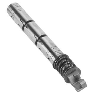
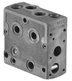
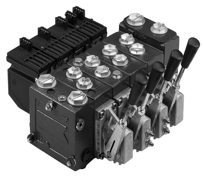
4 General general Valve system PVG 32 is a hydraulic load sensing valve designed to give maximum flexibility. From a simple load sensing directional valve, to an advanced electrically controlled load-independent proportional valve. The PVG 32 module system makes it possible to build up a valve group to meet requirements precisely.the compact external dimensions of the valve remain unchanged whatever combination is specified. General features PVG 32 Load-independent flow control: Oil flow to an individual function is independent of the load pressure of this function Oil flow to one function is independent of the load pressure of other functions Good regulation characteristics Energy-saving Up to 10 basic modules per valve group Several types of connection threads Low weight PVP pump side module Built-in pressure relief valve System pressure up to 350 bar [5075 psi] Pressure gauge connection Versions: Open centre version for systems with fixed displacement pumps Closed centre version for systems with variable displacement pumps Pilot oil supply for electrical actuator built into the pump side module Versions prepared for electrical LS unloading valve PVPX PVB, basic module Interchangeable spools Depending on requirements the basic module can be supplied with: Integrated pressure compensator in channel P Check valve in channel P Shock/suction valves LS pressure limiting valves individually adjustable for ports A and B Different spool variants Actuation modules The basic module is always fitted with mechanical actuator PVM, which can be combined with the following as required: Electrical actuator (11-32 V --- ) PVES proportional, super PVEH proportional, high performance - PVEA - proportional low hysteresis PVEM proportional, medium performance 4 520L0344 Rev FE Feb 2007
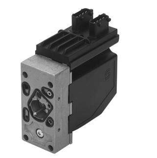
5 General general Actuation modules The basic module is always fitted with mechanical actuator PVM, which can be combined with the following as required: Electrical actuator (11-32 V --- ) PVES proportional, super performance PVEH proportional, high performance - PVEA - proportional, low hysteresis PVEM proportional, medium performance PVEO ON/OFF PVMD, cover for mechanical actuation PVMR, cover for mechanical detent PVMF, cover for mechanical float PVH, cover for hydraulic actuation Accessories Remote control units Electrical remote control units PVRE, PVRET PVREL PVRES Prof 1 Prof 1 CIP Hydraulic remote control unit PVRHH Electronics EHF, flow adjustment unit EHR, ramp generator EHS, speed control EHSC, closed loop speed control EHA, alarm logic EHC, closed loop position control PVG CIP CIP Configuration Tool 520L0344 Rev FE Feb
6 Notes 6 520L0344 Rev FE Feb 2007
7 Function PVG 32 valve group with open centre PVP (PVB with flow control spool) When the pump is started and the main spools in the individual basic modules (11) are in the neutral position, oil flows from the pump, through connection P, across the pressure adjustment spool (6) to tank. The oil flow led across the pressure adjustment spool determines the pump pressure (stand-by pressure). When one or more of the main spools are actuated, the highest load pressure is fed through the shuttle valve circuit (10) to the spring chamber behind the pressure adjustment spool (6), and completely or partially closes the connection to tank. Pump pressure is applied to the right-hand side of the pressure adjustment spool (6). The pressure relief valve (1) will open should the load pressure exceed the set value, diverting pump flow back to tank. In a pressure-compensated basic module the compensator (14) maintains a constant pressure drop across the main spool both when the load changes and when a module with a higher load pressure is actuated. With a non pressure-compensated basic module incorporating a load drop check valve (18) in channel P, the check valve prevents return oil flow. The basic module can be supplied without the load drop check valve in channel P for functions with over-centre valves. The shock valves PVLP (13) with fixed setting and the suction valves PVLA (17) on ports A and B are used for the protection of the individual working function against overload and/or cavitation. An adjustable LS pressure limiting valve (12) can be built into the A and B ports of pressure-compensated basic modules to limit the pressure from the individual working functions. The LS pressure limiting valves save energy compared with the shock valves PVLP: With PVLP all the oil flow to the working function will be led across the combined shock and suction valves to tank if the pressure exceeds the fixed setting. With LS pressure limiting valves an oil flow of about 2 l/min [0.5 US gal/min] will be led across the LS pressure limiting valve to tank if the pressure exceeds the valve setting. PVG 32 valve group with closed centre PVP (PVB with flow control spool) In the closed centre version an orifice (5) and a plug (7) have been fitted instead of the plug (4). This means that the pressure adjustment spool (6) will only open to tank when the pressure in channel P exceeds the set value of the pressure relief valve (1). In load sensing systems the load pressure is led to the pump regulator via the LS connection (8). In the neutral position the pump control sets the displacement so that leakage in the system is compensated for, to maintain the set stand-by pressure. When a main spool is actuated the pump regulator will adjust the displacement so that the set differential pressure between P and LS is maintained. The pressure relief valve (1) in PVP should be set at a pressure of approx. 30 bar [435 psi] above maximum system pressure (set on the pump or external pressure relief valve). 520L0344 Rev FE Feb
8 Function PVG 32 sectional drawing PVP PVB PVB 1. Pressure relief valve 2. Pressure reduction valve for pilot oil supply 3. Pressure gauge connection 4. Plug, open centre 5. Orifice, closed centre 6. Pressure adjustment spool 7. Plug, closed centre 8. LS connection 9. LS signal 10. Shuttle valve 11. Main spool 12. LS pressure limiting valve 13. Shock and suction valve, PVLP 14. Pressure compensator 15. LS connection, port A 16. LS connection, port B 17. Suction valve, PVLA 18. Load drop check valve 19. Pilot oil supply for PVE 20. Max. oil flow adjustment screws for ports A and B 8 520L0344 Rev FE Feb 2007
9 Function PVPC, Plug for external pilot oil supply PVPC with check valve for open centre PVP PVPC with check valve is used in systems where it is necessary to operate the PVG 32 valve by means of the electrical remote control without pump flow. When the external solenoid valve is opened, oil from the pressure side of the cylinder is fed via the PVPC through the pressure reducing valve to act as the pilot supply for the electrical actuators. This means that a load can be lowered by means of the remote control lever without starting the pump. The built-in check valve prevents the oil from flowing via the pressure adjustment spool to tank. With the pump functioning normally the external solenoid valve is closed to ensure that the load is not lowered due to the pilot supply oil flow requirement of approximately 1 l/min [0.25 US gal/min]. Please note: With closed centre PVP the external pilot oil supply can be connected to the pressure gauge connection without the use of a PVPC plug. 520L0344 Rev FE Feb
10 Function PVPC, Plug for external pilot oil supply PVPC without check valve for open or closed centre PVP PVPC without check valve is used in systems where it is necessary to supply the PVG 32 valve with oil from a manually operated emergency pump without directing oil flow to the pilot oil supply (oil consumption about 1 l/min) [0.25 US gal/min]. When the main pump is working normally, the oil is directed through the PVPC plug via the pressure reduction valve to the electrical actuators. When the main pump flow fails, the external shuttle valve ensures that the oil flow from the manually operated emergency pump is used to pilot open the over centre valve and lower the load. The load can only be lowered using the mechanical operating lever of the PVG 32 valve L0344 Rev FE Feb 2007
11 Function PVMR, Friction detent PVMR, Friction Detent The friction detent PVMR allows the directional spool to be held in any position, resulting in infinitely variable, reversible, pressure compensated flow. This can be sustained indefinitely without having to continue to hold the mechanical lever. Please note: PVMR should only be used together with PVB basic modules with pressure compensator. PVMR PVMF, Mechanical float position lock PVMF, Mechanical Float Position Lock This allows the float spool to be held in the float position after release of the mechanical handle. PVMF P A F (Standard assembly) PVMF P B F (Standard assembly) 520L0344 Rev FE Feb
12 Function PVBS, main spools for flow control (standard) When using standard flow control spools, the pump pressure is determined by the highest load pressure. This is done either via the pressure adjustment spool in open centre PVP (fixed displacement pumps) or via the pump regulator (variable displacement pumps). In this way the pump pressure will always correspond to the load pressure plus the stand-by pressure of the pressure adjustment spool or the pump regulator. This will normally give optimum and stable adjustment of the oil flow. PVBS, main spools for flow control (with linear characteristic) PVBS main spools with linear characteristic have less dead band than standard spools and a completely proportional ratio between control signal and oil flow in the range beyond the dead band. PVBS with linear characteristic must never be used together with PVEM electrical actuators. The interaction between the small dead band of the spools and the hysteresis of the PVEM actuator of 20% involves a risk of building up a LS pressure in neutral position. PVBS, main spools for pressure control In a few systems load sensing pump pressure may result in unstable adjustment of the oil flow and a tendency towards system hunting. This may be the case with working functions that have a large moment of inertia or over-centre valves. In such systems main spools for pressure control can be advantageous. The spools are designed in such a way that the pump pressure is controlled by the spool travel. The main spool must be displaced until the pump pressure just exceeds the load pressure before the working function is applied. If the main spool is held in this position, the pump pressure will remain constant even if the load pressure changes giving a stable system. The use of pressure control spools, however, also means that the oil flow is load dependent the dead band is load dependent the pump pressure can exceed the load pressure by more than is usual. Due to these factors it is recommended that pressure control spools are only used when it is known for certain that problems with stability will arise or already have arisen L0344 Rev FE Feb 2007
13 Function PVPX, Electrical LS unloading valve PVPX is a solenoid LS unloading valve. PVPX is fitted into the pump side module enabling a connection to be made between the LS and the tank lines. Thus the LS signal can be relieved to tank by means of an electric signal. For a PVP pump side module in open centre version the relief to tank of the LS signal means that the pressure in the system is reduced to the sum of the tank port pressure plus the neutral flow pressure for the pump side module. For a PVP pump side module in closed centre version the relief to tank of the LS signal means that the pressure is reduced to the sum of the tank port pressure for the pump side module plus the stand-by pressure of the pump. 520L0344 Rev FE Feb
14 Technical data PVG 32 Valve group The technical data for PVG 32 and PVPX are typical measured results. For the hydraulic system a mineral based hydraulic oil with a viscosity of 21 mm 2 /s [102 SUS] and a temperature of 50 C [122 F] was used. Max. pressure Oil flow rated (See characteristics page 31-36) Port P continuous 350 bar 1) [5075 psi] Port A/B 350 bar [5075 psi] Port T, static/dynamic 25 / 40 bar [365/580 psi] Port P 140/230 l/min 3) 4) [37/61 US gal/min] 3) 4) Port A/B, with press.comp. 100 l/min 2) [26.4 US gal/min] 2) Port A/B witout press.comp. 125 l/min [33 US gal/min] Spool travel, standard ± 7 mm [± 0.28 in] Spool travel, float position, spool Dead band, flow control spools Proportional range ± 4.8 mm ± 0.19 in] Float position ± 8 mm [± 0.32 in] Standard ±1.5 mm [± 0.06 in] Linear characteristic ± 0.8 mm [± 0.03 in] Max. internal leakage at 100 bar [2175 psi] and 21 mm2/s [102 SUS] A/B T without shock valveλϖεσ 20 cm 3 /min [1.85 in 3 /min] A/B T with shock valve 25 cm 3 /min [2.15 in 3 /min] Oil temperature (inlet temperature) Recommended temperature ΧC [ F] Min. temperature -30 C [-22 F] Max. temperature +90 C [194 F] Ambient temperature ΧC [ F] Oil viscosity Filtration (See page 55 Operating range mm 2 /s [ SUS] Min. viscosity 4 mm 2 /s [39 SUS] Max. viscosity 460 mm 2 /s [2128 SUS] Max. contamination (ISO 4406) 23/19/16 23/19/16 Oil consumtion in pilot oil pressure reduction valve 1 l/min [0.25 US gal/min] 1) With PVSI end plate. With PVS end plate max. 300 bar [4351 psi]. 2) For 130 l/min contact technical Sales Organization for Sauer-Danfoss 3) In open circuit systems with short P-hoses/tubes, attention should be paid to pressure peaks at flows >100 l/min. [26.4 US gal/min] 4) For system with Mid inlet PVPVM, see page 28 PVH, hydraulic actuation Regulation range 5-15 bar [ psi] Max. pilot pressure 30 bar [435 psi] Max. pressure on port T 1) 10 bar [145 psi] 1) The PVRHH remote control lever should be connected direct to tank L0344 Rev FE Feb 2007
15 Technical data PVM, mechanical actuation Regulation range, control lever ± 19.5 Regulation range Proportional range ±13.4 Float position 22.3 Operating force Neutral position Max. spool travel PVM + PVMD 2.2 ± 0.2 N m 2.8 ± 0.2 N m [5.0 ±1.8 lbf in] [6.3 ±1.8 lbf in] PVM + PVE 1) 2.2 ± 0.2 N m 2.8 ± 0.2 N m [5.0 ±1.8 lbf in] [6.3 ±1.8 lbf in] PVM + PVH 2.7 ±0.2 N m 7.1 ± 0.2 N m [23.9 ±1.8 lbf in] [62.8 ±1.8 lbf in] Spool displacement from neutral position 17 N m [3.8 lbf in] Operating force PVM + PVMR Spool displacement from any other position Spool displacement from neutral position 8.5 N m [73.3 lbf in] 22 N m [5.0 lbf in] PVM+PVMF Spool displacement into float position Spool displacement away from float position 60 N m [13.5 lbf in] 28 N m [6.3 lbf in] Control lever positions, see page 51 No ) PVE without voltage 520L0344 Rev FE Feb
16 Technical data pve Technical data The following technical data are from typical test results. For the hydraulic system a mineral based hydraulic oil with a viscosity of 21 mm2/s [102 SUS] and a temperature of 50 C [122 F] were used. PVEO and PVEM PVEO and PVEM Supply voltage U DC range 11 V to 15 V 22 V to 30 V rated 12 V DC 24 V DC max. ripple 5% Current consumption at rated voltage V V Signal voltage (PVEM) neutral A-port B-port 0.5 x UDC 0.25 UDC to 0.75 UDC Signal current at rated voltage (PVEM) 0.25 ma 0.50 ma Input impedance in relation to 0.5 UDC Power consumption 12 KΩ 8 W Reaction time PVEO and PVEM Supply voltage Disconnected by means of neutral switch Disconnected by means of neutral switch Constant voltage Constant voltage Function Reaction time from neutral position to max. spool travel Reaction time from max. spool travel to neutral position Reaction time from neutral position to max. spool position Reaction time from max. spool travel to neutral position PVEO ON/OFF s PVEO-R ON/OFF s PVEM Prop. medium s max rated min max rated min max rated min max rated min Hysteresis 1) rated % 1) Hysteresis is indicated at rated voltage and f = 0.02 Hz for one cycle (one cycle = neutral ->full A -> full B -> neutral L0344 Rev FE Feb 2007
17 Technical data pve Technical data (continued) PVEA, PVEH and PVES PVEA, PVEH and PVES Supply voltage U DC range 11 V to 32 V rated 11 V to 32 V max. ripple 5% Current consumption at rated voltage PVEH/PVES (PVEA) 0.57 (0.33) 12 V 0.3 (0.17) 24 V Signal voltage Signal current at rated voltage Input impedance in relation to 0.5 UDC Input capacitor neutral A-port B-port 0.5 x UDC 0.25 UDC to 0.75 UDC 0.25 ma to 0.70 ma 12 KΩ 100 ηf Power consumption PVEH/PVES (PVEA) 7 (3.5) W (PVEH/PVES) Active Passive Max. load Reaction time at fault Reaction time at fault 100 ma 60 ma 500 ms (PVEA: 750 ms) 250 ms (PVEA: 750 ms) Reaction time Supply voltage Function PVEA Prop. fine s PVEH Prop. high s PVES Prop. super s Disconnected by means of neutral switch Disconnected by means of neutral switch Constant voltage Constant voltage Reaction time from neutral position to max. spool travel Reaction time from max. spool travel to neutral position Reaction time from neutral position to max. spool travel Reaction time from max. spool travel to neutral position max rated min max rated min max rated min max rated min Hysteresis 1) rated 2% 4% 0% 1) Hysteresis is indicated at rated voltage and f = 0.02 Hz for one cycle (one cycle = neutral ->full A -> full B -> neutral. Spool position 520L0344 Rev FE Feb
18 Technical data Technical data (continued) Oil consumption PVEO and PVEM Supply voltage Function PVEO ON/OFF PVEM Prop. medium Without voltage Pilot oil flow per PVE neutral 0 l/min 0 l/min [0 US gal/min] [0 US gal/min] locked 0.1 l/min 0.1 l/min [0.026 US gal/min] [0.026 US gal/min] With voltage Pilot oil flow per PVE one actuation (neutral max.) continuous actuations l l [0.053 US gal] [0.053 US gal] 0.7 l/min 0.5 l/min [0.185 US gal/min] [0.132 US gal/min] Oil consumption PVEA, PVEH and PVES Supply voltage Function PVEA Prop. fine PVEH Prop. high PVES Prop. super Without voltage Pilot oil flow per PVE neutral 0 l/min 0 l/min 0.3 l/min [0 US gal/min] [0 US gal/min] [0.106 US gal/min] locked 0.4 l/min 0.1 l/min 0.1 l/min [0.132 US gal/min] [0.026 US gal/min] [0.053 US gal/min] With voltage Pilot oil flow per PVE one actuation (neutral max.) continuous actuations l l l [0.053 US gal] [0.053 US gal] [0.053 US gal] 1.0 l/min 0.7 l/min 0.8 l/min [0.200 US gal/min] [0.290 US gal/min] [0.290 US gal/min] Oil viscosity Oil temperature Oil viscosity range min. max mm 2 /s [ SUS] 4 mm 2 /s [39 SUS] 460 mm 2 /s [2128 SUS] Oil - temperature Rec. range min. max C [ F] -30 C [-22 F] 90 C [194 F] Note: Max. start up viscosity 2500 mm 2 /s Filtering Filtering in the hydraulic system Max. allowed degree of contamination (ISO 4406, 1999 version): 23/19/16 Ambient temperature Ambiant temperature C [ F] range Rec L0344 Rev FE Feb 2007
19 Technical data PVPX, electrical LS unloading valve Max. operating pressure 350 bar [5075 psi] Enclosure to IEC 529 IP65 Max. pressure drop at an oil flow of 0.10 l/min. [2.6 US gal/min] 2 bar [30 psi] Recommended temperature 30 to 60 C [86 to 140 F] Oil temperature (inlet -30 C Min. temperature temperature) [-22 F] Max. temperature 90 C [194 F] Max. coil surface temperature 155 C [311 F] Ambient temperature -30 to 60 C [-22 to 140 F] Operating range 12 to 75 mm 2 /s [65 to 347 SUS] Oil viscosity Min. viscosity 4 mm 2 /s [39 SUS] Max. viscosity 460 mm 2 /s [2128 SUS] Response time for LS pressure relief 300 ms Rated voltage 12 V 24 V Max. premissible deviation from rated supply voltage ± 10% Current consuption at at 22 C [72 F] coil temperature 1.55 A 0.78 A rated voltage at 110 C [230 F] coil temperature 1.00 A 0.50 A Power consumption at 22 C [72 F] coil temperature 19 W 19 W at 110 C [230 F] coil temperature 12 W 12 W 520L0344 Rev FE Feb
20 Electrical actuation function The philosophy of Sauer-Danfoss electro hydraulic actuation, type PVE, is integration of electronics, sensors and actuators into a single unit that interfaces directly to the proportional valve body Closed loop control All the proportional actuators feature an integrated feedback transducer that measures spool movement in relation to the input signal, and by means of a solenoid valve bridge, controls the direction, velocity and position of the main spool of the valve. The integrated electronics compensate for flow forces on the spool, internal leakage, changes in oil viscosity, pilot pressure, etc. This results in lower hysteresis and better resolution. Furthermore the electronics enable built in safety like fault monitoring, directional indication and LED light indication. Principle In principle the input signal (set-point signal) determines the level of pilot pressure which moves the main spool. The position of the main spool is sensed in the LVDT transducer which generates an electric feed-back signal registered by the electronics. The variation between the set-point signal and feed-back signal actuates the solenoid valves. The solenoid valves are actuated so that hydraulic pilot pressure drives the main spool into the correct position. Inductive transducer, LVDT (Linear Variable Differential Transformer). When the main spool is moved, a voltage is induced proportional to the spool position. The use of LVDT gives contact-free monitoring of the main spool position. This means an extra-long working life and no limitation as regards the type of hydraulic fluid used. In addition, LVDT gives a precise position signal of high resolution. Integrated pulse width modulation Positioning of the main spool in PVEA/PVEH/PVES is based on the pulse width modulation principle. As soon as the main spool reaches the required position, modulation stops and the spool is locked in position L0344 Rev FE Feb 2007
21 Electrical actuation ON/Off actuation With electrical ON/OFF actuation the main spool is moved from neutral to maximum stroke when power is connected. PVEO, ON/OFF Main features of PVEO: Compact Robust operation With Hirschmann or AMP connector Low electrical power PVEO-R, ON/OFF with hydraulic ramp Like PVEO, but for applications where longer reaction time is needed. Proportional actuation With electrical proportional actuation the main spool position is adjusted so that it corresponds to an electrical signal e.g. from a remote control unit. PVEM, proportional medium PVEM versions are recommended where there is a requirement for medium resolution proportional control and where reaction and hysteresis are not critical. Main features of PVEM: ON-OFF modulated Inductive transducer Medium hysteresis With Hirschmann connector only Low electrical power No set-up procedure PVEA, proportional fine PVEA versions are recommended where among the requirements are fault monitoring, low hysteresis, high resolution but where the reaction time is not critical. Main features of PVEA: Inductive transducer Integrated pulse width modulation AMP connector only As option with directional indicator (DI) Fault monitoring with transistor output for signal source. Low electrical power No set-up procedure 520L0344 Rev FE Feb
22 Electrical actuation Proportional actuation (continued) PVEH, proportional high Performance like PVEA but with fast reaction time. Main features of PVEH: Inductive transducer Integrated pulse width modulation Low hysteresis Fast reaction time Hirschmann or AMP connector As option with directional indicator (DI) Fault monitoring with transistor output for signal source Low electrical power No set-up procedure PVES, proportional super PVES versions are recommended for control systems requiring very low hysteresis to obtain a high resolution. For other technical data: see PVEH Hirschmann or AMP connector L0344 Rev FE Feb 2007
23 Fault monitoring system the fault monitoring system A fault monitoring system is provided in all PVEA, PVEH and PVES modules. The system is available in two versions: The active fault monitoring type, which provides a warning signal, deactivates the solenoid valves and drives the spool in neutral. The passive fault monitoring type, which provides a warning signal only. Both active and passive fault monitoring systems are triggered by three main events: 1. Input signal monitoring The input signal voltage is continuously monitored. The permissible range is between 15% and 85% of the supply voltage. Outside this range the section will switch into an active error state. 2. Transducer supervision If one of the wires to the LVDT sensor is broken or short-circuited, the section will switch into an active error state. 3. Supervision of the closed loop The actual position must always correspond to the demanded position (input signal). If the actual spool position is further than the demanded spool position (>12%, PVEA: >25%), the system detects an error and will switch into an active error state. On the other hand, a situation where the actual position is closer to neutral than that demanded will not cause an error state. This situation is considered in control. When an active error state occurs, the fault monitoring logic will be triggered: Active fault monitoring A delay of 500 ms (PVEA: 750 ms) before anything happens. The solenoid valve bridge will be disabled and all solenoid valves will be released. An alarm signal is sent out through the appropriate pin connection. This state is memorized and continues until the system is actively reset (by turning off the supply voltage). Passive fault monitoring A delay of 250 ms (PVEA: 750 ms) before anything happens. The solenoid valve bridge will not be disabled but still control the main spool position. An alarm signal is sent out through the appropriate pin connection. This state is not memorized. When the erroneous state disappears, the alarm signal will turn to passive again. However, the signal will always be active for a minimum of 100 ms when triggered. To prevent the electronics from going into an undefined state, a general supervision of the power supply and the internal clock frequency is made. This function applies to PVEA, PVEH and PVES - and will not activate fault monitoring: 1. High supply voltage The solenoid valves are disabled when the supply voltage exceeds 36 V, and the main spool will return/stay in neutral. 2. Low supply voltage: The solenoid valves are disabled when the supply voltage falls below 8.5 V, and the main spool will return/stay in neutral. 520L0344 Rev FE Feb
24 Electrical actuation the fault monitoring system (continued) 3. Internal clock The solenoid valves are disabled when the internal clock frequency fails, and the main spool will return/stay in neutral. WWARNING It s up to the customer to decide on the required degree of safety for the system (see PVE series 4 catalogue DKMH.PK.570.A1.02, page 19). Note: 1. Different degrees of safety are described on pages 56 to The fault monitoring does not work if the supply voltage to PVEA/PVEH/PVES is cut off for example by a neutral position switch (see page 56). 3. When using PVEA/PVEH/PVES with passive fault monitoring it s up to the customer to decide on the required degree of safety for the system (see page 56). fault monitoring specification Type Fault monitoring Delay before error out Error mode Error output status Fault output on PVE 1) LED light Memory (reset needed) PVEO No fault PVEM monitoring No fault Low < 2 V Green ms Input signal faults Flashing red Active (PVEA: 750ms) Transducer (LVDT) High U DC Yes PVEA Constant red Close loop fault PVEH No fault Low < 2 V Green - PVES 250 ms Input signal faults Flashing red Passive (PVEA: 750ms) Transducer (LVDT) High ~U DC No Constant red Close loop fault 1) Measured between fault output pin and ground L0344 Rev FE Feb 2007
25 Electrical actuation pvea/pveh/pves, connection to fault monitoring output Green Transistor output function Normal Example of connected components A: External relay B: Solenoid valve (e.g. PVPX) Fault Red Transistor output function Example of connected components A: External relay B: Solenoid valve (e.g. PVPX) Via an external relay the pin pos. 3 can be connected to a solenoid valve which will relieve the LS-signal to tank, e.g. PVPX. Other connections possible: a solenoid valve to relieve the pump oil flow a signal lamp, an alarm horn pump cut-out, etc. 520L0344 Rev FE Feb
26 Modules and code numbers PVP, Pump side moduls Symbol Description Code number Open centre pump side module for pumps with fixed displacement. P = G 1 /2 P = 7 /8 in B B5200 For purely machanically actuated valve groups P = G 3 /4 P = 1 1 /16 in B B5300 Closed centre pump side module for pumps with vaiable displacement. P = G 1 /2 P = 7 /8 in B B5201 For purely machanically actuated valve groups P = G 3 /4 P = 1 1 / 16 in B B5301 Open centre pump side module for pumps with fixed displacement. P = G 1 /2 P = 7 /8 in B B5210 With pilot oil supply for electrically actuatet valves P = G 3 /4 P = 1 1 /16 in B B5310 Closed centre pump side module pumps with variable displacement. With pilot oil supply. for electrically actuated valves Open centre pump side module for pumps with fixed displacement. With pilot oil supply for electrically actuatet valves Connection for electrical LS unloading valve, PVPX Closed centre pump side module pumps with variable displacement With pilot oil supply Connection for electrical LS unloading valve, PVPX P = G 1 /2 P = 7 /8 in - 14 P = G 3 /4 P = 1 1 /16 in - 14 P = G 1 /2 P = 7 /8 in - 14 P = G 3 /4 P = 1 1 /16 in - 14 P = G 1 /2 P = 7 /8 in - 14 P = G 3 /4 P = 1 1 /16 in B B B B B B B B B B B B5313 Connection: P = G 1 /2; 14 mm deep or G 3 /4; 16 mm deep. LS/M = G 1 /4; 12 mm deep; T = G 3 /4; 16 mm deep. P = 7 /8 in - 14; 0.65 in deep or 1 1 /16 in - 12; 0.75 in deep. LS/M = 1 /2 in - 20; 0.47 in deep. T = 1 1 /16 in - 12; 0.75 in deep L0344 Rev FE Feb 2007
27 Modules and code numbers PVP, Pump side moduls Symbol Description Code number Open centre pump side module for pumps with fixed displacement. For mechanical actuated valves. Connection for LS unloading valve, PVPX P = G 3 /4 157B5102 Closed centre pump side module for pumps with vaiable displacement. For mechanical actuated valves. P = G 3 /4 157B5103 Connection for LS unloading valve, PVPX Open centre pump side module for pumps with fixed displacement. P = G 3 /4 157B5180 With pilot oil supply for electrica actuation and connection for pilot oil pressure P = 7 /8 in B5380 Closed centre pump side module pumps with variable displacement. P = G 3 /4 157B5181 With pilot oil supply for electrica actuation and connection for pilot oil pressure P = 7 /8 in B5381 Open centre pump side module for pumps with fixed displacement. P = G 3 /4 157B5190 With pilot oil supply for electrica actuation and connection for pilot oil pressure P = 7 /8 in B5390 Closed centre pump side module pumps with variable displacement P = G 3 /4 157B5191 With pilot oil supply for electrica actuation and connection for pilot oil pressure P = 7 /8 in B5391 Connection: P = G 1 /2; 14 mm deep or G 3 /4; 16 mm deep. LS/M = G 1 /4; 12 mm deep; T = G 3 /4; 16 mm deep. P = 7 /8 in - 14; 0.65 in deep or 1 1 /16 in - 12; 0.75 in deep. LS/M = 1 /2 in - 20; 0.47 in deep. T = 1 1 /16 in - 12; 0.75 in deep. 520L0344 Rev FE Feb
28 Modules and code numbers PVPV and PVPVM, Pump side modules Symbol Description Code number PVPV Closed center pump side module for pumps with variable displacement. P and T = G1 157B5938 With pilot supply for electrical actuation Max. pump pressure = 350 bar [5075 psi] Max. pump flow = 150 l/min [40 US gal/min] PVPV Closed center pump side module for pumps with vaiable displacement. P and T = 1 5 /16 UN P and T = G1 157B B5941 With pilot supply for electrical actuation With facility for shock and suction valve PVLP 63 Max. pump pressure = 350 bar [5075 psi] Max. pump flow = 150 l/min [40 US gal/min] PVPVM Closed center pump side module for pumps with variable displacement. P and T 1 5 /16 UN P and T = G1 157B B5937 With pilot supply for electrical actuation Max. pump pressure = 350 bar [5075 psi] Max. pump flow = 230 l/min [61 US gal/min] PVPVM Closed center pump side module for pumps with variable displacement. P and T 1 5 /16 UN P and T = G1 157B B5940 MA og LS : G¼ [ 9 /16-18 UNF] With pilot supply for electrical actuation With facility for shock and suction valve PVLP 63 Max. pump pressure = 350 bar [5075 psi] Max. pump flow = 230 l/min [61 US gal/min] P and T 1 5 /16 UN 157B L0344 Rev FE Feb 2007
29 Modules and code numbers PVB, Basic modules without adjustable LS A/B pressure limiting valves Symbol Code number Description No facilities for Facilities for shock valves A/B shock valves A/B Without load drop check valve and G 1 /2 pressure compensator 14 mm deep Can be used where load holding valves prevent oil from flowing back 7 /8 in -14 through channel P in deep 157B B B B6430 Load drop check valve G 1 /2 14 mm deep 157B B /8 in in deep 157B B6530 G 1 /2 14 mm deep Load drop check valve. LS A/B shuttle valve. To be used with 7 /8 in -14 float position spools in deep - 157B B6536 G 1 /2 157B B mm deep With non-damped compensator valve 7 /8 in in deep 157B B L0344 Rev FE Feb
30 Modules and code numbers PVB, Basic modules - without adjustable LS a/b pressure limiting valves Symbol Code number Description No facilities for Facilities for shock valves A/B shock valves A/B With damped compensator valve G 1 /2 14 mm deep 7 /8 in in deep 157B B PVB, Basic modules - with adjustable LS a/b pressure limiting valves Symbol Code number Description No facilities for Facilities for shock valves A/B shock valves A/B With non-damped compensator valve. G 1 /2 Adjustable LSA/B 14 mm deep pressure limiting valves External LS connection port A/B. Also used for 7 /8 in -14 float position spools in deep 157B B B B6633 Damped compensator G 1 /2 valve. 14 mm deep Adjustable LSA/B pressure limiting valves External LS connection port A/B 7 /8 in in deep 157B B L0344 Rev FE Feb 2007
31 Modules and code numbers PVM, Mechanical actuation Symbol Description PVM, Standard, spring centered 22.5 Individual oil flow adjustment to ports A and B 37.5 Without actuation lever and base. Shaft for mounting of actuation lever PVM, as standard, witout actuation lever With base for mounting of actuation lever 37.5 PVM, Standard, spring. Individual oil flow 22.5 adjustment to ports A and B. (Anodized) Code number with stop screws w/o stop screws 157B B B B B B B B B B B PVMD, cover for Mechanical actuation Symbol Description Code number PVMD, Cover for purely mechanically operated valve. 157B0001 PVH, hydraulic actuation Symbol Description Code number PVH, Cover for hydraulic remote control G 1/4, 12 mm deep 9/16-18 UNF; 0.54 in deep 157B B0007 PVMR, friction detent Symbol Description Code number PVMR, Friction detent 157B0004 PVMF, mechanical float position Symbol Description Code number PVMF Mechanical float position lock 157B L0344 Rev FE Feb
32 Modules and code numbers code numbers for use on PVG B... PVE for PVG 32 PVEO, ON/OFF actuation Code no. 157B... PVEO Hirschmann connector 12 V 24 V AMP connector 12 V 24 V Deutsch connector 12 V 24 V ON/OFF ON/OFF with ramp ON/OFF anodized not available PVEM, proportional actuation Code no. 157B... PVEM Hirschmann connector 12 V 24 V Standard Float PVEA/PVEH/PVES, proportional actuation Code no. 157B... PVEA PVEA-DI PVEH PVEH-DI PVES Hirschmann connector V AMP connector V Deutsch connector V Standard, active fault monitoring Not available Standard, passive fault monitoring Not available Standard, active anodized Not available Standard, active fault monitoring Not available Standard, passive fault monitoring Not available Standard, active fault monitoring Standard, passive fault monitoring PVEH float position, act. fault Standard, passive anodized Not available Float, active fault monitoring 4332 Not available - Standard, active fault monitoring Not available Standard, passive fault monitoring Not available % hysteresis, active fault monitoring % hysteresis, passive fault monitoring L0344 Rev FE Feb 2007
33 Modules and code numbers PVLA, suction valve (fitted in PVB) Symbol Description Code number Suction valve for port A and/orb. 157B2001 Plug for connecting the nonactive port to tank, when using a single acting spool. 157B2002 PVLp, Shock and suction valve (fitted in PVB) Symbol Description Shock and suction valve for port A and/or B. (Not adjustable) Setting bar [psi] Code number B B B B B B B B B B B B B B B B B B B B L0344 Rev FE Feb
34 Modules and code numbers pvs, END PLATE Symbol Description Code number PVS, without active elements. No connections 157B B2020 PVS, without active elements. Max. intermittend LX pressure 250 bar [3625 psi] G 1 /8 10 mm deep 157B /8 in - 24; 0,39 in deep 157B2021 PVSI, without active elements Without connections. PVSI, without active elements LX connections. Max. intermittend LX pressure: 350 bar [5075 psi] 157B B2004 G 1 /4 10 mm deep 157B /2 in - 20; 0,47 in deep 157b2005 pvas, ASSEMBLY KIT Code no, 157B PVB s PVB + PVPVM Weight kg [lb] 0.1[0.2] 0.15 [0.3] 0.25 [0.6] 0.30 [0.7] 0.40 [0.9] 0.45 [1.0] 0.50 [1.1] 0.60 [1.3] 0.65 [1.4] 0.70 [1.6] 0.80 [1.7] 0.85 [1.8] 0.9 [2.0] pvas, ASSEMBLY KIT for PVPVM Description Code number 157B... 1 PVB 2 PVB 3 PVB 4 PVB 5 PVB 6 PVB 7 PVB 8 PVB 9 PVB 10 PVB Tie bolts and seals *) for one PVB on PVGI (combination 120 / 32) L0344 Rev FE Feb 2007
35 Modules and code numbers PVPX, electrical LS unloaded valve Symbol Description Code number PVPX, Normally open: LS pressure relieved with no signal to PVPX PVPX, Normally closed: LS pressure relieved with no signal to PVPX PVPX, Normally open with manual override: LS pressure relieved with no signal to PVPX Manual override DE-selects LS-pump 12 V 24 V 12 V 24 V 12 V 24 V 26 V 157B B B B B B B Plug 157B5601 PVPC, plug for external pilot oil supply Symbol Description Code number G 1 /2, 12 mm deep 157B5400 PVP, Plug without check valve for open or closed centre 1 /2 in - 20; 0.47 in deep - PVP, Plug with check valve for open centre G 1 /2, 12 mm deep 1 /2 in - 20; 0.47 in deep 157B B L0344 Rev FE Feb
36 Technical characteristics general The characteristics in this catalogue are typical measured results. During measuring a mineral based hydraulic oil with a viscosity of 21 mm 2 /s [102 SUS] at a temperature of 50 C [122 F] was used. PVP, Pump side module Pressure relief valve characteristic in PVP The pressure relief valve is set at an oil flow of 15 l/min [4.0 US gal/min]. Setting range: 30 to 350 bar [435 to 5075 psi] (with PVSI end plate) and (300 bar [4351 psi] (with PVS end plate) Neutral flow pressure in PVP, open centre L0344 Rev FE Feb 2007
37 Technical characteristics PVB, Basic module Oil flow characteristics The oil flow for the individual spool depends on type of basic module (with/without compensation) type of pump (fixed or variable displacement). Please note: The letters AA, A, B, etc. denote spool types, see pages 62 to 69. The characteristic below is shown for spool travel in both directions. All other characteristics are shown for spool travel in one direction only. Pressure-compensated PVB, open or closed centre PVP The oil flow is dependent on the supplied pump oil flow. The characteristics are plotted for a pump oil flow, Q P, corresponding to the rated max. spool oil flow, Q N. Increasing the pump oil flow to 1,4 Q N will give the same oil flow on the eighth as on the first basic module. U S = Signal voltage U DC = Supply voltage 1 = First PVB after PVP 8 = Eighth PVB after PVP 520L0344 Rev FE Feb
38 Technical characteristics PVB, Basic module Pressure compensated PVB, open or closed centre PVP Linear characteristic Please note: For PVB basic modules without pressure compensator the top ends of the characteristics (max. oil flow) are different so they correspond to those of the standard flow control spools, see characteristics for PVB without pressure compensator. U S = Signal voltage U DC = Supply voltage 1 = First PVB after PVP 8 = Eighth PVB after PVP L0344 Rev FE Feb 2007
39 Technical characteristics PVB, Basic module PVB without pressure compensation, open centre PVP Oil flow as a function of spool travel. The spool flow is dependent on the supplied oil flow, Q P. The characteristics apply to supply oil flow of 130 l/min [34.3 US gal/min] with the actuation of one basic module. If several basic modules are activated at the same time, the characteristic depends on the load pressure of the actuated basic modules. 520L0344 Rev FE Feb
40 Technical characteristics PVB, Basic module PVB without pressure compensation, open centre PVP Oil flow Q A/B as a function of supplied pump oil flow (Q P ) curves for fully displaced flow control spools. The pressure drop of any oil flowing back to tank (Q P - Q A/B ) is read on the curve for neutral flow pressure in PVP, page L0344 Rev FE Feb 2007
41 Technical characteristics PVB, Basic module PVB without pressure compensation, closed centre PVP Set pressure difference between pump pressure and LS signal = 10 bar [145 psi]. 520L0344 Rev FE Feb
42 Technical characteristics PVB, Basic module PVB without pressure compensation, closed centre PVP Set pressure difference between pump pressure and LS signal = 20 bar [290 psi]. The oil flow is dependent on the pressure difference between the pump pressure and the LS signal. Normally the pressure difference is set at the LS pump regulator L0344 Rev FE Feb 2007
43 Technical characteristics PVB, Basic module Pressure drop PVB at max. main spool travel Pressure drop PVB for open spool in neutral position Load-independent oil flow, pressure-compensated PVB Oil flow at LS pressure limiting, pressure-, compensated PVB 520L0344 Rev FE Feb
44 Technical characteristics PVLP, Shock and suction valve PVLP, shock valve PVLP is set at an oil flow of 10 l/min [2.6 US gal/min]. The shock valve PVLP is designed to absorb shock effects. Consequently, it should not be used as a pressure relief valve. If the working function requires the use of a pressure relief valve, a PVB basic module with built-in LS A/B pressure limiting valve should be used. PVLA, Suction valve PVLP/PVLA, suction valve L0344 Rev FE Feb 2007
45 Technical characteristics Pressure control spools, characteristics in extreme positions Size A: Size B: 1: See example page 46 Size C: Size D: 2: See example page L0344 Rev FE Feb
46 Technical characteristics Pressure control spools, characteristics in extreme positions Size E: Pressure build-up Max. oil flow can be reduced by about 50% without limitation of maximum pressure by limiting the main spool travel from 7 mm [0.28 in] to 5.5 mm [0.22 in] Examples of how to use the characteristics for pressure control spools Example of determining the oil flow Given: - Spool type B - Pressure setting P P: 160 bar [2320 psi] - Load pressure, LS A/B: 100 bar [1450 psi] Result: - Oil flow = 75 l/min [19.8 US gal/min] (see page 45, size B). Example of determining spool size Given: - Max. oil flow, Q A/B : 90 l/min [23.8 US gal/min] - Pressure setting P P : 150 bar [2175 psi] - Load pressure, P LSA : 125 bar [1810 psi] Result: - D spool (see page 45, size D) Please note: Normally a smaller spool can be chosen with pressure control. It is our experience that the spool can be one size smaller than with normal flow control L0344 Rev FE Feb 2007
47 Technical characteristics Characteristics for float position main spools Characteristics; oil flow, spool travel and voltage The spools have 4,8 mm spool travel in direction A and 8 mm travel in direction B: 4.8 mm [0.19 in] spool displacement in direction A gives max. oil flow to port A 4.8 mm [0.19 in] spool displacement in direction B gives max. oil flow to port B 8 mm [0.32 in] spool displacement in direction B gives completely open float position A/B T. Pressure drop A/B T at max. spool travel within the proportional range (4.8 mm) [0.19 in). Spools D and E have the same opening area for forward flow and return flow. Spool E can give 100 l/min [26.4 US gal/min] pressure compensated oil flow due to a higher pressure drop across spool E. This occurs during spool actuation only. 520L0344 Rev FE Feb
48 Technical characteristics Characteristics for float position main spools Pressure drop A/B T in float position L0344 Rev FE Feb 2007
49 Dimensions dimensions F : Shock and suction valve, PVLP G : Pressure gauge connection; G 1 /4, 12 mm deep [ 1 /2 in-20, 0.47 in deep] H : Plug for external pilot oil supply, PVPC; G 1 /2, 12 mm deep [ 1 /2 in-20, 0.47 in deep] I : Electrical LS unloading valve, PVPX J : LS connection; G 1 /4, 12 mm deep [ 1 /2 in-20, 0.47 in deep] K : Fixing holes; M8 min. 10 [ 5 /16 in-18, 0.47 in deep] L : Port A and B; G 1 /2, 14 mm deep [ 7 /8 in-14, 0.65 in deep] M : LX connection: PVS; G 1 /8, 10 mm deep [ 3 /8 in-24, 0.39 in deep] PVSI; G 1 /4, 12 mm [0.47 in] deep [ 1 /2 in-20, 0.47 in deep] N : LS pressure limiting valve O : Tank connection; G 3 /4, 16 mm deep [1 1 /16 in-12, 0.75 in deep] P : Pressure relief valve Q : Pump connection; G 1 /2, 14 mm deep or G 3 /4, 16 mm deep [ 7 /8 in-14, 0.65 in deep or 1 1 /16 in-12, 0.75 in deep] R : LS A and LS B connections; G 1 /4, 12 mm [0.47 in] deep [ 1 /2 in-20, 0.47 in deep] S : Pp, pilot pressure connection G ¼ L1 L2 PVB mm [in] [3.23] [5.12] [7.01] [8.90] [10.79] [12.68] [14.57] [16.46] [18.35] [20.24] [562] [610] mm in] [5.51] [7.44] [9.37] [11.30] [13.23] [15.16] [17.09] [19.02] [20.95] [22.87] [622] [670] 520L0344 Rev FE Feb
PVG 32 Proportional Valves. Technical Information
 PVG 32 Proportional Valves Technical Information Contents CONTENTS Page General...3 Function...5 PVG 32 valve group...5 PVPC, plug for external pilot oil supply...7 PVMR, friction detent...9 PVMF, mechanical
Hydrau Hyd. ydr ique. Hydraulics. Hydraulik H. Hydraulics. aulique aulik q ue. Hydraulique. ulique. Hydraulique. Hydraulique Hydraulik.
 Catalogue Load-independent Proportional valve Type PVG 32 With mechanical actuation With electric remote control and mechanical actuation With hydraulic remote control and mechanical actuation ydr ique
PVG 120 Proportional Valves. Technical Information
 PVG 120 Proportional Valves Technical Information Contents CONTENTS General...3 Function...5 Hydraulic systems...7 Technical data...9 Electrical actuation... 12 Modules and code numbers... 16 PVP, pump
Proportional Valve Group PVG 32
 MAKING MODERN LIVING POSSIBLE Technical Information Proportional Valve Group PVG 32 powersolutions.danfoss.com Revision history Table of revisions Date Changed Rev August 2015 PVPX modules description
PVG 100 Proportional Valve. Technical Information
 PVG 100 Proportional Valve Technical Information Contents GENERAL FUNCTION PVG 100 TECHNICAL DATA MODULES AND CODE NUMBERS General... 4 Valve system... 4 General features PVG 100... 4 PVP - Pump side module...
Proportional Valve Group PVG 32
 MAKING MODERN LIVING POSSIBLE Technical Information Proportional Valve Group PVG 32 powersolutions.danfoss.com Revision History Table of Revisions Date Changed Rev Feb 214 Spec. sheet update HE Jan 214
PVG 32 PROPORTIONAL VALVE Sauer TECHNICAL INFORMATION AND OTHER OPERATING CONDITIONS
 Sauer TECHNICAL INFORMATION AND OTHER OPERATING CONDITIONS Effective filtration is the most important precondition in ensuring that a hydraulic system performs reliably and has a long working life. Filter
PVG 120 Proportional Valves. Technical Information
 PVG 120 Proportional Valves Technical Information Contents Revision History Contents Function Hydraulic Systems Technical Data Electrical Actuation Modul and Code Numbers Technical Characteristics Dimensions
Hydraulics. Hydraulik
 Catalogue Load-independent Proportional Valve Type PVG 120 With mechanical actuation With electrical remote control and mechanical actuation With hydraulic remote control and mechanical actuation ulics
Proportional Valve Group PVG 120
 Technical Information Proportional Valve Group PVG 120 powersolutions.danfoss.com Revision history Table of revisions Date Changed Rev March 2017 minor updates 1002 Mar 2014 Chapters re-order, Modules
Proportional Valve Group PVG 16
 MAKING MODERN LIVING POSSIBLE Technical Information Proportional Valve Group PVG 16 powersolutions.danfoss.com Revision History Table of Revisions Date Changed Rev Jan 2014 Converted to Danfoss layout
PVG 32 Proportional Valve Group
 Technical Information PVG 32 Proportional Valve Group www.danfoss.com Revision history Table of revisions Date Changed Rev December 218 Major revision of document. 111 September 218 Safety topic, new PVBS
PVG 16 Proportional Valve Group. Technical Information
 PVG 16 Proportional Valve Group Revisions, Literature Reference Revision History Table of revisions Date Page Changed Rev Oct 2012 - New edition. AA Literature Reference Literature reference for PVG products
Proportional Valve Group PVG 100
 MAKING MODERN LIVING POSSIBLE Technical Information Proportional Valve Group PVG 1 powersolutions.danfoss.com Revision History Table of Revisions Date Changed Rev Jan 214 Converted to Danfoss layout DITA
PVG 16 Proportional Valve Group. Technical Information
 PVG 16 Proportional Valve Group Revisions, Literature Reference Revision History Table of revisions Date Page Changed Rev Oct 2012 - New edition. AA Feb 2013 All Major update BA Literature Reference Literature
Proportional Valve Group PVG 100
 Technical Information Proportional Valve Group PVG 100 www.danfoss.com Revision history Table of revisions Date Changed Rev May 2018 minor edits 0502 March 2016 Updated for Engineering Tomorrow design.
PVG 120 Proportional Valves. Technical Information
 PVG 120 Proportional Valves Technical Information Revision History, Contents Table of Revisions Date Page Changed Rev Apr 2010 Various Layout, drawings and others HA Sep 2010 29, 44 Drawing, new back cover
PVG 120 Proportional Valves. Service Parts Manual
 PVG 120 Proportional Valves Service Parts Manual Contents and Data Survey CONTENTS AND DATA SURVEY Page Sectional drawing... 3 Identification...4 Installation PVG... 5 Spare parts... 22 Pos. 1: PVP, pump
Proportional Valve Group PVG 16/32/128/256
 Service and Parts Manual Proportional Valve Group www.danfoss.com Revision history Table of revisions Date Changed Rev October 208 Combined installation guides, service and parts manuals 00 2 Danfoss October
Proportional Valve Group PVG 16
 Technical Information Proportional Valve Group PVG 16 powersolutions.danfoss.com Revision history Table of revisions Date Changed Rev March 2016 Minor update in PVHC technical characteristics 0303 March
Proportional Valve Group PVG 16
 Technical Information Proportional Valve Group PVG 16 powersolutions.danfoss.com Revision history Table of revisions Date Changed Rev February 2017 Major update. 0401 March 2016 Minor update in PVHC technical
Proportional Valve Group PVG 128/256
 Service and Parts Manual Proportional Valve Group powersolutions.danfoss.com Revision history Table of revisions Date Changed Rev July 207 First edition 00 2 Danfoss July 207 AX00000346en-US00 Contents
Phased Out Products. Proportional Valve Group PVG 83. Tech Note MAKING MODERN LIVING POSSIBLE
 MAKING MODERN LIVING POSSIBLE Tech Note Proportional Valve Group PVG 83 Valve system PVG 83 is a hydraulic load sensing valve designed to give the customer just the valve he needs. From a simple load sensing
PVG 32 Specification Sheet. Subsidiary/Dealer. Customer. Application B-Port. B-Port. Subsidiary/Dealer PVG No.
 Remarks BPort PHYDPVG323 PVG 32 Proportional Valves s Subsidiary/Dealer PVG No. Customer Customer No. Appliation Revision No. Funtion APort PVG 32 Sheet Subsidiary/Dealer PVG No. Customer Customer No.
Proportional Valve Group PVG 120
 MAKING MODERN LIVING POSSIBLE Service Manual Proportional Valve Group PVG 120 powersolutions.danfoss.com Revision history Table of revisions Date Changed Rev May 2014 Converted to Danfoss layout DITA CMS,
EHPS Steering Valve PVE Actuation Module OSPCX CN Steering Unit
 MAKING MODERN LIVING POSSIBLE Technical Information EHPS Steering Valve PVE Actuation Module OSPCX CN Steering Unit powersolutions.danfoss.com Revision history Table of revisions Date Changed Rev May 2015
PVG 120 Proportional Valves. Specifications
 PVG 120 Proportional Valves s Ordering guidance and remote control units ORDERING GUIDANCE The module selection chart and the order form are both divided into fields. Each module has its own field: 0:
Proportional Valve Group PVG 120
 MAKING MODERN LIVING POSSIBLE Specification Proportional Valve Group PVG 120 powersolutions.danfoss.com Revision history Table of revisions Date Changed Rev May 2014 Converted to Danfoss layout DITA CMS
EHPS Steering Valve PVE Actuation Module OSPCX CN Steering Unit. Technical Information
 EHPS Steering Valve PVE Actuation Module OSPCX CN Steering Unit Technical Information A Wide Range of Steering Components Revision History Table of Revisions Date Page Changed Rev Mar 2009 35 Note added
PVG 32 Metric Ports. Technical Information
 PVG 32 Metric Ports Technical Information T Revisions Revision History Table of Revisions Date Page Changed Rev Dec 2010 40 New back cover C Mar 2012 ll Layout changes, and change in the table, page 21.
Steering OSPE Steering Valve
 Technical Information Steering powersolutions.danfoss.com Revision history Table of revisions Date Changed Rev July 2016 Corrected drawing of OSPEC LSRM with PVED-CLS in a system with variable pump, GPS
EHPS Steering Valve PVE Actuation Module OSPCX CN Steering Unit. Technical Information
 EHPS Steering Valve PVE Actuation Module OSPCX CN Steering Unit Technical Information A Wide Range of Steering Components Revision History Table of Revisions Date Page Changed Rev Mar 2009 35 Note added
Flow sharing control block in mono block / sandwich plate design M6-15
 Flow sharing control block in mono block / sandwich plate design M6-15 RE 64321 Edition: 01.2015 Replaces: 05.2012 Size 15 Series 3X Maximum operating pressure on pump side 350 bar on consumer side 420
Flow sharing control block in mono block / sandwich plate design M6-22
 Flow sharing control block in mono block / sandwich plate design M6-22 RE 64322 Edition: 01.2015 Replaces: 05.2012 Size 22 Series 3X Maximum operating pressure on pump side 350 bar on consumer side 420
TMVW Orbital Motors. Technical Information
 Orbital Motors Technical Information A Wide Range of Orbital Motors A Wide Range of Orbital Motors F300030 Tif Sauer-Danfoss is a world leader within production of low speed orbital motors with high torque.
Servo solenoid valves with positive overlap Position feedback (Lvdt DC/DC ±10 V)
") Servo solenoid valves with positive overlap Position feedback (Lvdt DC/DC ±10 V) RE 29087/01.05 1/22 Replaces: 05.04 Type 4WRL 10 35, symbols E. / W. Nominal size 10, 16, 25, 35 Unit series 3X Maximum
Servo solenoid valves with positive overlap Position feedback (Lvdt DC/DC ±10 V) RE 29087/01.05 1/22 Replaces: 05.04 Type 4WRL 10 35, symbols E. / W. Nominal size 10, 16, 25, 35 Unit series 3X Maximum
OSPB, OSPC, OSPR, OSPD Open Center Steering units OSPB Closed Center Steering units TAD Torque amplifiers. Technical Information
 OSPB, OSPC, OSPR, OSPD Open Center Steering units OSPB Closed Center Steering units TAD Torque amplifiers Technical Information A wide range of steering components A WIDE RANGE OF STEERING COMPONENTS F300599
VED05MJ - PROPORTIONAL DIRECTIONAL CONTROL VALVES WITH OBE & POSITION FEEDBACK
 CONTINENTAL HYDRAULICS VED05MJ PROPORTIONAL DIRECTIONAL CONTROL VALVES WITH OBE & POSITION FEEDBACK VED05MJ - PROPORTIONAL DIRECTIONAL CONTROL VALVES WITH OBE & POSITION FEEDBACK 5505 WEST 123RD STREET
2-way proportional throttle valve for block installation
 -way proportional throttle valve for block installation RE 90/07.05 Replaces: 03.00 / Types FE; FEE Size 6 Component series X Maximum operating pressure 35 bar Maximum flow 90 L/min bei p = 0 bar H4538
Proportional directional control valve, pilot operated with on-board electronics (OBE) and inductive position transducer
 and inductive position transducer") Proportional directional control valve, pilot operated with on-board electronics (OBE) and inductive position transducer RE 29076/12.05 1/24 Type 4WRBKE Nominal size (NG) 10, 16, 27, 35 Unit series 1X
Proportional directional control valve, pilot operated with on-board electronics (OBE) and inductive position transducer RE 29076/12.05 1/24 Type 4WRBKE Nominal size (NG) 10, 16, 27, 35 Unit series 1X
Servo solenoid valves with on-board electronics (OBE)
") Servo solenoid valves with on-board electronics (OBE) RE 29045/10.05 Replaces: 01.05 1/12 Type 5WRPE 10 Size 10 Unit series 2X Maximum working pressure P 1, P 2, A, B 210 bar, T 50 bar Nominal flow rate
Servo solenoid valves with on-board electronics (OBE) RE 29045/10.05 Replaces: 01.05 1/12 Type 5WRPE 10 Size 10 Unit series 2X Maximum working pressure P 1, P 2, A, B 210 bar, T 50 bar Nominal flow rate
Servo solenoid valves with on-board electronics (OBE)
") Servo solenoid valves with on-board electronics (OBE) RE 29037/10.05 Replaces: 01.05 1/12 Type 4WRPEH 10 Size 10 Unit series 2X Maximum working pressure P, A, B 315 bar, T 250 bar Nominal flow rate 50...100
Servo solenoid valves with on-board electronics (OBE) RE 29037/10.05 Replaces: 01.05 1/12 Type 4WRPEH 10 Size 10 Unit series 2X Maximum working pressure P, A, B 315 bar, T 250 bar Nominal flow rate 50...100
油力油壓工業股份有限公司 YOULI HYDRAULIC INDUSTRIAL CO.,LTD. ISO 9001:2008 QA100189
 ISO 9001:2008 Q100189 油力油壓工業股份有限公司 YOULI HYDRULIC INDUSRIL CO.,LD. V-4 Contents roportional Valve ump side module.5 End plate.6 asic module.7 general dimensions.8 ump side module options.10 System with
Servo solenoid valves with positive overlap and on-board electronics (OBE)
") Electric Drives and Controls Hydraulics Linear Motion and Assembly Technologies Pneumatics Service Servo solenoid valves with positive overlap and on-board electronics (OBE) RA 2989/1.5 1/24 Model 4WRLE
Electric Drives and Controls Hydraulics Linear Motion and Assembly Technologies Pneumatics Service Servo solenoid valves with positive overlap and on-board electronics (OBE) RA 2989/1.5 1/24 Model 4WRLE
Servo solenoid valves with positive overlap and on-board electronics
 Servo solenoid valves with positive overlap and on-board electronics RE 29089/01.05 1/22 Replaces: 05.04 Type 4WRLE 10...35, symbols E./W. Nominal size 10, 16, 25, 35 Unit series 3X Maximum working pressure
Proportional pressure reducing valve, pilot operated, with on-board electronics (OBE) and position feedback
 and position feedback") Proportional pressure reducing valve, pilot operated, with on-board electronics (OBE) and position feedback Type DREBE6X Nominal size (NG) 6 Unit series 1X Maximum working pressure P 315 bar, T 250 bar
Proportional pressure reducing valve, pilot operated, with on-board electronics (OBE) and position feedback Type DREBE6X Nominal size (NG) 6 Unit series 1X Maximum working pressure P 315 bar, T 250 bar
4/2 servo solenoid valves with on-board electronics (OBE), positive overlap and position feedback
, positive overlap and position feedback") Electric Drives and Controls Hydraulics Linear Motion and Assembly Technologies Pneumatics Service 4/2 servo solenoid valves with on-board electronics (OBE), positive overlap and position feedback RA 29024/01.05
Electric Drives and Controls Hydraulics Linear Motion and Assembly Technologies Pneumatics Service 4/2 servo solenoid valves with on-board electronics (OBE), positive overlap and position feedback RA 29024/01.05
Series 20 Axial Piston Pumps. Technical Information
 Series 20 Axial Piston Pumps Technical Information General Description INTRODUCTION Sauer-Danfoss a world leader in hydraulic power systems has developed a family of axial piston pumps. DESCRIPTION Sauer-Danfoss
Pilot operated proportional directional valves
 /6 Pilot operated proportional directional valves 6. Type WRLE Sizes to 7 Up to 5 bar Up to L/min Contents Function and configuration Symbols Specifications Technical data -5 Electrical connection Technical
Servo solenoid valves with on-board electronics (OBE)
") Electric Drives and Controls Hydraulics Linear Motion and Assembly Technologies Pneumatics Service Servo solenoid valves with on-board electronics (OBE) RA 29045/01.05 1/12 Model 5WRPE 10 Size 10 Unit
Electric Drives and Controls Hydraulics Linear Motion and Assembly Technologies Pneumatics Service Servo solenoid valves with on-board electronics (OBE) RA 29045/01.05 1/12 Model 5WRPE 10 Size 10 Unit
TPV Variable Displacement Closed Loop System Axial Piston Pump THE PRODUCTION LINE OF HANSA-TMP HT 16 / M / 852 / 0815 / E
 HYDRAULIC COMPONENTS HYDROSTATIC TRANSMISSIONS GEARBOXES - ACCESSORIES Certified Company ISO 9001-14001 ISO 9001 Via M. L. King, 6-41122 MODENA (ITALY) Tel: +39 059 415 711 Fax: +39 059 415 729 / 059 415
Servo solenoid valves with on-board electronics (OBE)
") Servo solenoid valves with on-board electronics (OBE) RE 29077/01.05 1/16 Replaces: 01.03 Type 4WRVE10...25 Size 10, 16, 25 Unit series 2X Maximum working pressure P, A, B 350 bar, T, X, Y 250 bar Nominal
Servo solenoid valves with on-board electronics (OBE) RE 29077/01.05 1/16 Replaces: 01.03 Type 4WRVE10...25 Size 10, 16, 25 Unit series 2X Maximum working pressure P, A, B 350 bar, T, X, Y 250 bar Nominal
Flow sharing control block in sandwich plate design M7-25
 Flow sharing control block in sandwich plate design M7-25 RE 64297 Edition: 07.2016 Replaces: 06.2012 Size 25 Series 3X Maximum working pressure on the pump side 380 bar on the consumer side 420 bar Maximum
Sectional Directional Control Valve RSQ 240
 Sectional Directional Control Valve RSQ 0 Key valve features RSQ 0 is a sectional open center valve, designed for max. operating pressures up to 50 bar and max. pump flows up to 00 l/min. It is available
Post-Compensated Proportional Valve CV2000LS
 www.nimco-controls.com Post-Compensated Proportional Valve CV2000LS Smart Solutions... for the Future Contents Page 5 Page 6 Page 7 Page 8 Page 9 Page 10 Page 11 Page 12 Page 13 Page 14 Page 15 Page 16
CONTINENTAL HYDRAULICS VED03MX
 CONTINENTAL HYDRAULICS VED03MX HIGH PERFORMANCE, SERVO-PROPORTIONAL DIRECTIONAL CONTROL VALVE 5505 WEST 123RD STREET SAVAGE, MN 55378-1299 / PH: 952.895.6400 / WWW.CONTINENTALHYDRAULICS.COM VED03MX HIGH
Series 20 Axial Piston Pumps. Technical Information
 Series 20 Axial Piston Pumps Technical Information General Description INTRODUCTION Sauer-Danfoss a world leader in hydraulic power systems has developed a family of axial piston pumps. DESCRIPTION Sauer-Danfoss
Servo solenoid valves with on-board electronics (OBE)
") Servo solenoid valves with on-board electronics (OBE) RE 29088/01.05 1/18 Replaces: 05.04 Type 4WRLE10...35, symbols V/V1 Size 10, 16, 25, 35 Unit series 3X Maximum working pressure P, A, B 350 bar, T,
Servo solenoid valves with on-board electronics (OBE) RE 29088/01.05 1/18 Replaces: 05.04 Type 4WRLE10...35, symbols V/V1 Size 10, 16, 25, 35 Unit series 3X Maximum working pressure P, A, B 350 bar, T,
Proportional pressure relief valve, pilot operated, with on-board electronics (OBE) and position feedback
 and position feedback") Proportional pressure relief valve, pilot operated, with on-board electronics (OBE) and position feedback RE 29159/07.05 1/10 Type DBEBE6X Nominal size 6 Unit series 1X Maximum working pressure P 315 bar,
Proportional pressure relief valve, pilot operated, with on-board electronics (OBE) and position feedback RE 29159/07.05 1/10 Type DBEBE6X Nominal size 6 Unit series 1X Maximum working pressure P 315 bar,
Sectional Directional Control Valve RS 220
 Sectional Directional Control Valve RS 0 RS 0 is a sectional open center valve designed for max. operating pressures up to 00 bar and max. pump flows up to 0 l/min. Technical data Pressure and flow values*
Electrohydraulic Actuators PVE Series 7
 Service Manual Electrohydraulic Actuators powersolutions.danfoss.com Revision history Table of revisions Date Changed Rev August 017 First edition 0101 Danfoss August 017 AX00000348en-US 0101 Contents
4/3-way servo solenoid directional control valves, pilot operated, with electrical position feedback (Lvdt DC/DC ±10V)
") 1/16 4/3-way servo solenoid directional control valves, pilot operated, with electrical position feedback (Lvdt DC/DC ±1V) RE 2986/1.9 Replaces: 1.5 Type 4WRL 1...35, symbols V/V1 Sizes (N) 1, 16, 25,
1/16 4/3-way servo solenoid directional control valves, pilot operated, with electrical position feedback (Lvdt DC/DC ±1V) RE 2986/1.9 Replaces: 1.5 Type 4WRL 1...35, symbols V/V1 Sizes (N) 1, 16, 25,
Proportional flow control valve 2-way version, Type 2FRE 10, Huade América 1
 Proportional flow control valve 2-way version, Type 2FRE 10, 16... Huade América 1 EIJING HUADE HYDRAULIC INDUSTRIAL GROUP CO.,LTD. Proportional flow control valve 2-way version Type 2FRE 10 16... Size
4/4 directional control valves, direct operated, with electrical position feedback and integrated electronics (OBE)
") 4/4 directional control valves, direct operated, with electrical position feedback and integrated electronics (OBE) Type 4WRPEH RE 29121 Edition: 2014-01 Size 6 Component series 3X Maximum operating pressure
4/4 directional control valves, direct operated, with electrical position feedback and integrated electronics (OBE) Type 4WRPEH RE 29121 Edition: 2014-01 Size 6 Component series 3X Maximum operating pressure
Pilot-Operated Proportional DC Valve Series D*1FH
 Characteristics The pilot-operated proportional DC valves series of the D*1FH series are high-performance valves with electronic spool position feedback. These valves are available in sizes NG10 to NG2
D660 Series Servo-Proportional Control Valves with Integrated Electronics ISO 4401 Size 05 to 10
 D660 Series Servo-Proportional Control Valves with Integrated Electronics ISO 4401 Size 05 to 10 OVERVIEW Section Page MOOG SERVO-PROPORTIONAL CONTROL VALVES Overview 2 3 Technical Data 4 5 Electronics
Directional Control Valve CV550
 www.nimco-controls.com Directional Control Valve CV550 Smart Solutions... for the Future Contents Page 5 Page 6 Page 7 Page 8 Page 9 Page 10 Page 11 Page 12 Page 13 Page 14 Page 16 Page 17 Page 18 Page
Steering unit LAGZ. Data sheet. Series 2 x
 Steering unit LAGZ Data sheet Nominal sizes 125 620 Series 2 x Maximum flow 50 l / min HE 11868 / 09.2017 2 LAGZ HE 11868 / 09.2017 Page Content 4 4 5 6 7 8 9 10 11 12 13 14 Features Ordering details Function,
OML and OMM Orbital motors. Technical Information
 OML and OMM Orbital motors Technical Information OML and OMM A wide range of orbital motors F300030.TIF A WIDE RANGE OF ORBITAL MOTORS Sauer-Danfoss is a world leader within production of low speed orbital
Steering EHi Steering Valve
 Technical Information Steering powersolutions.danfoss.com Revision history Table of revisions Date Changed Rev January 2018 Function, Technical Characteristics, Coding ; minor corrections and additions
Catalog HY /US SERIES CAVITY DESCRIPTION FLOW PRESSURE PAGE NO. LPM/GPM BAR/PSI
 Catalog HY15-352/US Contents SERIES CAVITY DESCRIPTION FLOW PRESSURE PAGE NO. LPM/GPM BAR/PSI PRESSURE RELIEVING AP1B2YP... 2G... Increase /Increase Current...5.3/1.4... 35/5... 7-8 AP2B2YP... C8-2...
MONOBLOCK DIRECTIONAL CONTROL VALVES
 MONOBLOCK DIRECTIONAL CONTROL VALVES CONTENTS: RM0...... RM5...... RM40P...... RM80...... RMD90...... MRP70... Page 1/19&/19 /19...5/19 6/19...10/19 11/19...15/19 16/19&17/19 18/19&19/19 MONOBLOCK DIRECTIONAL
TECHNICAL PAPER 1002 FT. WORTH, TEXAS REPORT X ORDER
 I. REFERENCE: 1 30 [1] Snow Engineering Co. Drawing 80504 Sheet 21, Hydraulic Schematic [2] Snow Engineering Co. Drawing 60445, Sheet 21 Control Logic Flow Chart [3] Snow Engineering Co. Drawing 80577,
Proportional pressure reducing valve, pilot operated, with inductive position transducer
 Proportional pressure reducing valve, pilot operated, with inductive position transducer RE 29182/07.05 1/10 Type DREB6X Nominal size 6 Unit series 1X Maximum working pressure P 315 bar, T 250 bar Maximum
VED*MJ PILOT OPERATED DIRECTIONAL CONTROL VALVES WITH OBE & FEEDBACK
 CONTINENTAL HYDRAULICS VED*MJ PILOT OPERATED DIRECTIONAL CONTROL VALVES WITH OBE & FEEDBACK 5505 WEST 123RD STREET SAVAGE, MN 55378-1299 / PH: 952.895.6400 / WWW.CONTINENTALHYDRAULICS.COM DURABLE VED*MJ
VED05MG CONTINENTAL HYDRAULICS PROPORTIONAL DIRECTIONAL CONTROL VALVES WITH OBE VED05MG - PROPORTIONAL DIRECTIONAL CONTROL VALVES WITH OBE
 CONTINENTAL HYDRAULICS VED05MG PROPORTIONAL DIRECTIONAL CONTROL VALVES WITH OBE 5505 WEST 123RD STREET SAVAGE, MN 55378-1299 / PH: 952.895.6400 / FAX: 952.895.6444 / WWW.CONTINENTALHYDRAULICS.COM POWERFUL
4/3 proportional directional control valve, without position control, with on-board electronics (OBE)
") 4/3 proportional directional control valve, without position control, with on-board electronics (OBE) Type 4WRBAE..E.. /..W.. Nominal size (NG) 6, 10 Unit series 2X Maximum working pressure P, A, B 315
4/3 proportional directional control valve, without position control, with on-board electronics (OBE) Type 4WRBAE..E.. /..W.. Nominal size (NG) 6, 10 Unit series 2X Maximum working pressure P, A, B 315
Safety for Hydraulics
 Safety for Hydraulics Compac-type Proportional Valves Reference: 301-P-9050025-EN-04 Issue: 08.2015 1/30 Contents Page 1 Functional description... 4 1.1 The load check-back signal... 4 1.2 The flow characteristics...
Pilot control unit with end position lock for the remote control of directional valves
 Pilot control unit with end position lock for the remote control of directional valves RE 64 553/02.07 1/12 Replaces : 05.05 Type 4THF6 or 5THF6 Series 2X Contents Functional description, section, symbol
Variable displacement axial piston pumps,
 LVP 04 T E Variable displacement axial piston pumps, Edition: 04/04.2000 Replaces: 04/10.99 DISPLACEMENTS From To PRESSURE Max. continuous Max. intermittent Max. peak 29 cm 3 /rev 73 cm 3 /rev 280 bar
4/3-way servo solenoid directional control valves, pilot operated, with electrical position feedback and on-board electronics
 1/16 4/3-way servo solenoid directional control valves, pilot operated, with electrical position feedback and on-board electronics RE 2989/1.9 Replaces: 1.5 Type 4WRLE 1...35, symbols E./W. Sizes (N) 1,
4/3-way servo solenoid directional control valves, pilot operated, with electrical position feedback and on-board electronics
 4/3-way servo solenoid directional control valves, pilot operated, with electrical position feedback and on-board electronics Type 4WRLE 1...35, symbols E./W. Sizes (N) 1, 16, 25, 27, 35 Unit series 3
4/3 directional control valve, pilot operated, with electric position feedback and integrated electronics (OBE)
") 4/ directional control valve, pilot operated, with electric position feedback and integrated electronics (OBE) RE 977/.1 Replaces: 1.9 1/16 Type 4WRVE 1...7, symbols V, V1 Sizes 1, 16, 5, 7 Component series
4/ directional control valve, pilot operated, with electric position feedback and integrated electronics (OBE) RE 977/.1 Replaces: 1.9 1/16 Type 4WRVE 1...7, symbols V, V1 Sizes 1, 16, 5, 7 Component series
VED*MJ - PILOTED PROPORTIONAL DIRECTION CONTROL VALVES WITH OBE & FEEDBACK
 CONTINENTAL HYDRAULICS VED*MJ PILOTED PROPORTIONAL DIRECTION CONTROL VALVES WITH OBE & FEEDBACK 5505 WEST 123RD STREET SAVAGE, MN 55378-1299 / PH: 952.895.6400 / WWW.CONTINENTALHYDRAULICS.COM VED*MJ PILOTED
4/3 servo solenoid valves with on-board electronics (OBE), positive overlap and position feedback
, positive overlap and position feedback") 4/3 servo solenoid valves with on-board electronics (OBE), positive overlap and position feedback RE 29025/01.05 1/16 Replaces: 05.04 Type 4WRPE..E.. /..W.. Size 6, 10 Unit series 2X Maximum working pressure
4/3 servo solenoid valves with on-board electronics (OBE), positive overlap and position feedback RE 29025/01.05 1/16 Replaces: 05.04 Type 4WRPE..E.. /..W.. Size 6, 10 Unit series 2X Maximum working pressure
Spreader Valves SPR-2FFL12, SPR-2FFLC12 & SPR-2FFLW86
 Spreader Valves, & SCHEMATIC MODEL PRESSURE FLOW* WEIGHT Quick Reference Page 3 Spreader Valve, Dual Flow Regulation, Compensated, Manual Dump, Gear Pump Circuit 138 bar [2000 psi] [30 US g/m] 2.62 kg
Catalog HY /US SERIES CAVITY DESCRIPTION FLOW PRESSURE PAGE NO. LPM/GPM BAR/PSI
 Catalog HY15-351/US Contents SERIES CAVITY DESCRIPTION FLOW PRESSURE PAGE NO. LPM/GPM BAR/PSI PRESSURE RELIEVING AP1B2YP... 2G... Increase /Increase Current...5.3/1.4... 35/5... 7-8 AP2A2... C8-2... Increase
Proportional cartridge throttle valve, with inductive position transducer, pilot operated
 Proportional cartridge throttle valve, with inductive position transducer, pilot operated RE 29215/09.05 1/18 Type FESX Nominal size 16, 25, 32, 40, 50 Unit series 1X Maximum working pressure A, B, X 315
Proportional pressure reducing valve, pilot operated
 Proportional pressure reducing valve, pilot operated RE 29177/07.05 1/10 Type DRE6X Nominal size 6 Unit series 1X Maximum working pressure P 315 bar, T 250 bar Maximum flow rate 40 l/min List of Contents
Cartridge Valves Technical Information. Spreader Valves. Spreader Valves SCHEMATIC MODEL PRESSURE FLOW* WEIGHT SPR-2FFL12 SPR-2FFLC12 SPR-2FFLW86
 SPR-2FFL12, SPR-2FFLC12 & SPR-2FFLW86 SCHEMATIC MODEL PRESSURE FLOW* WEIGHT Page 2 SPR-2FFL12 138 bar [2000 psi] [30 US g/m] 2.62 kg [5.90 lb] Spreader Valve, Dual Flow Regulation, Compensated, Manual
D661-G...A Series Servovalve With Bushing and Integrated 24 Volt Electronics ISO 4401 Size 05
 D661-G...A Series Servovalve With Bushing and Integrated 24 Volt Electronics ISO 4401 Size 05 OVERVIEW Section Page MOOG SERVO-PROPORTIONAL CONTROL VALVES Overview 2 3 Technical Data 4 5 Performance Specs.
Steering unit LAGC. Data sheet
 Steering unit LAGC Data sheet Nominal sizes Series Maximum flow HE 14365 / 09.2017 40 1000 1 x and 2 x 80 l / min 2 LAGC HE 14365 / 09.2017 Page Content 4 4 5 6 7 8 9 10 11 12 13 14 Features Ordering details
Proportional Valves. Proportional solenoid valves for pressure and flow control
 Proportional Valves Proportional solenoid valves for pressure and flow control EATON Vickers Screw-In Cartridge Valves V-VLOV-MC-E4 September, 7 - Electro- Proportional Valves Section Contents Typical
P2060 P2075 P2105 P2145 P3105 P3145
 Technical Information Technical Features P2 Series Compact design Low noise level Service friendly Reliable Long-lasting Flexible Easy to install High self-priming speed Technical Data P3 Series P2 Series
Priority valve LPS. Data sheet. Series 1 x
 Priority valve LPS Data sheet Nominal sizes 40 160 Series 1 x Maximum flow 40 160 l / min HE 27548 / 10.2017 2 LPS HE 27548 / 10.2017 Page Content 4 4 5 6 7 8 9 10 11 12 13 14 Features Ordering details
Directional servo-valve of 4-way design
 Courtesy of CM/Flodyne/Hydradyne Motion Control Hydraulic Pneumatic Electrical Mechanical (0) 426-54 www.cmafh.com Directional servo-valve of 4-way design Type 4WSE3E 32 Size 32 Component series 5X Maximum
4/2 servo solenoid valves with positive overlap and position feedback (Lvdt AC/AC)
") Electric Drives and Controls Hydraulics Linear Motion and Assembly Technologies Pneumatics Service 4/2 servo solenoid valves with positive overlap and position feedback (Lvdt AC/AC) Model 4WRP..E.. /..W..
Electric Drives and Controls Hydraulics Linear Motion and Assembly Technologies Pneumatics Service 4/2 servo solenoid valves with positive overlap and position feedback (Lvdt AC/AC) Model 4WRP..E.. /..W..
Proportional flow control valve 2-way versiontype 2FRE 6...RC
 Proportional flow control valve 2-way versiontype 2FRE 6...RC Huade América 1 BEIJING HUADE HYDRAULIC INDUSTRIAL GROUP CO.,LTD. Proportional flow control valve 2-way version Type 2FRE 6...RC Size 6 up
4/3 and 4/2 Proportional directional valve elements L8580 with flow (EDC-P) sharing control (LUDV concept) PATENT PENDING
 sharing control (LUDV concept) PATENT PENDING") / and / Proportional directional valve elements L88 with flow (EDC-P) sharing control (LUDV concept) PATENT PENDING L88 (EDC-P) RE 181-9 Edition:.16 Replaces: 7.1 7.1 Size 6 Series Maximum operating pressure
/ and / Proportional directional valve elements L88 with flow (EDC-P) sharing control (LUDV concept) PATENT PENDING L88 (EDC-P) RE 181-9 Edition:.16 Replaces: 7.1 7.1 Size 6 Series Maximum operating pressure
VED*MG - PILOT OPERATED PROPORTIONAL DIRECTIONAL CONTROL VALVES WITH OBE
 CONTINENTAL HYDRAULICS VED*MG PILOT OPERATED PROPORTIONAL DIRECTIONAL CONTROL VALVES WITH OBE 5505 WEST 123RD STREET SAVAGE, MN 55378-1299 / PH: 952.895.6400 / WWW.CONTINENTALHYDRAULICS.COM VED*MG PILOT