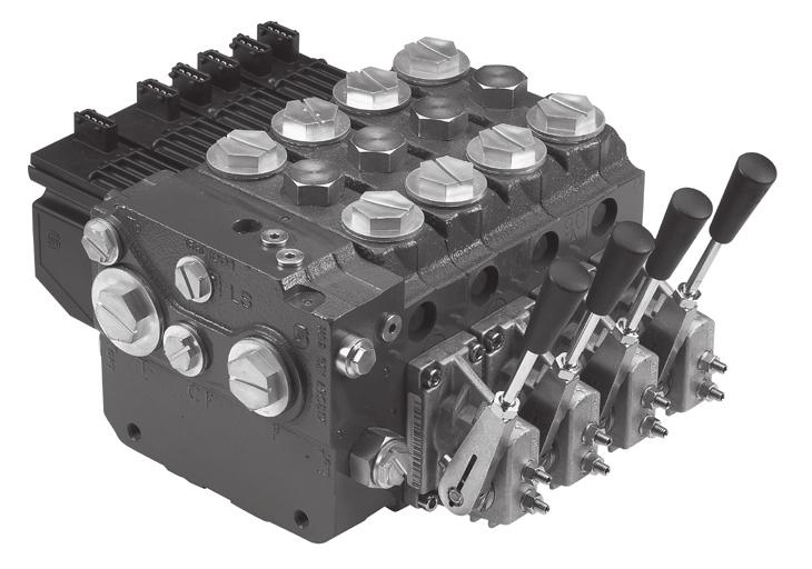
PVG 100 Proportional Valve. Technical Information
|
|
|
- Patricia Cummings
- 6 years ago
- Views:
Transcription
1 PVG 100 Proportional Valve Technical Information
2 Contents GENERAL FUNCTION PVG 100 TECHNICAL DATA MODULES AND CODE NUMBERS General... 4 Valve system... 4 General features PVG PVP - Pump side module... 4 PVB basic module... 4 Actuation modules... 4 PVG 100 valve group with open center PVP... 5 PVG 100 valve group with closed center PVP... 5 PVG 100 sectional drawing... 6 PVG 100 Valve group... 7 PVH, hydraulic actuation... 7 PVM, mechanical actuation... 8 PVE, reaction time... 8 PVE, oil consumption and hysteresis... 9 PVEO... 9 PVEA, PVEH and PVES... 9 PVP 100 inlet modules...10 PVP 100 accessories for open center pump side modules...11 PVB 100 basic modules...11 PVB 32 Basic modules with T PVBZ 32 basic modules with T0... Code number for use on PVG PVM, mechanical actuation...14 PVMD, cover for mechanical actuation...14 PVH, hydraulic actuation...14 PVMR friction detent...14 PVMF, mechanical float position...14 PVE for PVG PVLA, suction valve (fitted in PVB)...16 PVLP, shock and suction valve (fitted in PVB)...17 PVT 100 tank module...18 PVTI 100/32 interface module...18 Assembly kit PVG 100 / PVSI / PVT...18 Assembly kit PVG 100 /PVTI interface module...18 Assembly kit PVB 32 (combo PVG 100) Sauer-Danfoss. All rights reserved. Printed in Europe. Sauer-Danfoss accepts no responsibility for possible errors in catalogs, brochures and other printed material. Sauer-Danfoss reserves the right to alter its products without prior notice. This also applies to products already ordered provided that such alterations aren t in conflict with agreed specifications. All trademarks in this material are properties of their respective owners. Sauer-Danfoss and the Sauer-Danfoss logotype are trademarks of the Sauer-Danfoss Group. Front cover illustrations: PA270004, F301102, F301196, F Drawing: L0720 Rev. B 02/2006
3 Contents TECHNICAL CHARACTERISTICS DIMENSIONS HYDRAULIC SYSTEMS OTHER OPERATING CONDITIONS MODULES AND CODE NUMBERS MODULE SELECTION CHART ORDER SPECIFICATION SPECIFICATION SHEET General...19 PVP, pump side module...19 Open center flow rating...19 PVB, Basic module...20 PVLP, shock and suction valve...22 PVLA, suction valve...22 Valve dimension, PVG 100, open center PVP...23 Valve dimension, PVG100 / 32, closed center...24 Valve dimension, PVG 100, closed center PVP with integrated priority valve...25 General dimensions...26 Hydraulic systems...27 Oil...28 Mineral oil...28 Non-flammable fluids...28 Biodegradable oils...28 Particle content, degree of contamination...28 Filtration...29 System filters...29 Internal filters...29 Standard spools (elec. and mechanical actuation)...30 Standard spools (Hydraulic actuation)...30 Spools for friction detent PVMR...31 Spools for mechanical float position PVMF...31 Module selection chart...32 Order specification...34 Specification Sheet L0720 Rev. B 02/2006 3
4 General GENERAL Valve system PVG 100 is a hydraulic load sensing valve, designed to fulfill customer requirements. From a simple load sensing directional valve to an advanced electro hydraulic controlled load independent proportional valve. The PVG 100 modular system makes it possible to build up a valve group to fulfill customer requirements. The compact external dimensions of the valve remains unchanged whatever combination is specified L0720 Rev. B 02/2006 General features PVG 100 Load independent flow control Oil flow to an individual function is independent of the load on this function Oil flow to one function is independent of the load pressure of other functions Anti saturation (flow sharing) In case of anti saturation, pump flow is shared between all functions, independent of load. Good regulation characteristics Up to 8 PVB 100 basic modules per valve group Up to 10 PVB 100/32 basic modules per valve group BSP and UNF connection threads PVP - Pump side module Build in load sense relief valve System pressure up to 350 bar (5075 psi) Full Flow dump valve (open center only) Pilot supply shut off Versions Open center version for systems with fixed displacement pumps Accumulator gauge connection Pressure gauge connection Pilot gauge connection Closed center versions for systems with variable displacement pump Integrated priority valve Integrated pilot supply valve PVB basic module Integrated pilot operated check valves in A and B work ports for low internal leakage Integrated pressure compensator Interchangeable spools Depending on requirements the basic module can be supplied with : Shock/suction valves Different spools Actuation modules The basic module is always fitted with mechanical actuator PVM, which can be combined with the following as required: Electrical actuator PVES super proportional PVEH proportional high PVED Can-bus interface PVEA proportional, fine PVEO ON/OFF PVH, cover for hydraulic actuation PVMD, for mechanical actuation PVMR, for friction detent PVMF, for mechanical detent, float
5 Function PVG 100 PVG 100 VALVE GROUP WITH OPEN CENTER PVPF When the pump is started and the main spools in the individual basic modules are in the neutral position, oil flows from the pump, through connection P, across the pressure matching spool to tank. The oil flow led across the pressure matching spool determines the pump pressure (stand-by pressure). When one or more of the main spools are actuated, the highest load pressure is fed through the shuttle valve circuit to the spring chamber behind the pressure matching spool, and completely or partially closes the connection to tank. Pump pressure is applied to the opposite side of the pressure matching spool. The pressure relief valve will open should the load pressure exceed the set value, diverting pump flow back to tank. In a pressure-compensated basic module the compensator maintains a constant pressure drop across the main spool both when the load changes and when a module with a higher load pressure is actuated. Besides independent flow the other advantage of post-compensated work sections is the ability to control multifunction operation when flow demand exceeds pump capacity. This means that all work sections will continue to function regardless of differences in their load and regardless of the pump flow. The flow relationships specified between functions will be maintained over the full flow range of the pump. The shock valves PVLP with fixed setting and the suction valves PVLA on ports A and B are used for the protection of the individual working function against overload and/or cavitation. PVG 100 VALVE GROUP WITH CLOSED CENTER PVPV In load sensing systems the load pressure is led to the pump regulator via the LS connection. In the neutral position the pump control sets the displacement so that leakage in the system is compensated for, to maintain the set stand-by pressure. When a main spool is actuated the pump regulator will adjust the displacement so that the set differential pressure between P and LS is maintained. The pressure relief valve in PVP should be set at a pressure of approx. 30 bar [435 psi] above maximum system pressure (set on the pump or external pressure relief valve). With post-compensated valves, the rating of the A- and B work-port flow will depend on the pressure drop across the main spool PVBS. In open center systems, this pressure drop (standby-pressure) is generated by the volume of pump flow led to tank across the pressure adjusting spool in the inlet PVPF. Since the pressure drop varies with pump flow volume led to tank, also the A- and B work-port flow will vary (see further details page 19). In closed center systems, the pressure drop across the main spool equals the standby setting of the pump, measured at the P-port of the valve. The A and B work port flow will remain unchanged as long as the standby is unchanged. 520L0720 Rev. B 02/2006 5
6 Function PVG 100 PVG 100 SECTIONAL DRAWING PVP WITH INTEGRATED PRIORITY VALVE 1. LS relief valve 2. LS connection 3. Priority spool for CF 4. LS connection for steering unit 5. Shuttle valve 6. Pilot operated check valve, POC 7. LS line 8. Logic cartridge for POC 9. Pressure compensator 10. Shock and suction valve, PVLP 11. Main spool, PVBS 12. Max. oil flow adjustment screws for ports A and B. LS comp (LS signal sent back to compensators) 6 520L0720 Rev. B 02/2006
7 Technical data PVG 100 VALVE GROUP The technical data for PVG 100 are typical measured results. For the hydraulic system a mineral based hydraulic oil with a viscosity of 21 mm 2 /s [102 SUS] and a temperature of 50 C [122 F] was used. Port P continuous 350 bar [5075 psi] Max. pressure Port A/B 350 bar [5075 psi] Port T, static / dynamic Port T0, static / dynamic 25 bar/40 bar 5 bar/10 bar [365/580 psi] [75/145 psi] Oil flow, rated Port P* 250 l/min [66 US gal/min] (See characteristics, see page 20 Port A/B, with press. comp. 180 l/min [47.6 US gal/min] Spool travel, standard ± 7 mm [±0.28 in] Spool travel, float Proportional range 5.5 mm [±0.22 in] position spool P B F Float position 8 mm [±0.32 in] Dead band, flow control spools Standard ± 1.5 mm [±0.06 in] Max. spool leakage at 100 bar [1450 psi] and 21 mm 2 /s [102 SUS] A/B T, without shock valve 20 cm 3 /min [1.85 in 3 /min] A/B T, with shock valve 25 cm 3 /min [2.15 in 3 /min] Max. internal leakage with pilot operated check valve A/B T, without shock valve 1 cm 3 /min [0.06 in 3 /min] at 200 bar [2900 psi] and A/B T, with shock valve 6 cm 3 /min [0.37 in 3 /min] 21 mm 2 /s [102 SUS] Oil temperature Recommended temperature C [ F] (inlet temperature) Min. temperature -30 C [ 22 F] Max. temperature +90 C [194 F] Ambient temperature C [ F] Operating range mm 2 /s [ SUS] Oil viscosity Min. viscosity 4 mm 2 /s [39 SUS] Max. viscosity 460 mm 2 /s [2128 SUS] Filtration Max. contamination (See page 29) (ISO 4406) 23/19/16 23/19/16 * see also page 10 and 11 PVH, HYDRAULIC ACTUATION Regulation range 5-15 bar [ psi] Max. pilot pressure 30 bar [435 psi] Max. pressure on port T 1) 10 bar [145 psi] 1) The PVRHH remote control (hydraulic joystick) lever should be connected direct to tank. 520L0720 Rev. B 02/2006 7
8 Technical data PVM, MECHANICAL ACTUATION Regulation range, control lever stander spool Proportional range ±19.5 Regulation range, float Proportional range ±15.3 Float position 22.3 Neutral position Max. spool travel PVM + PVMD 22 ± 3 N m 28 ± 3 N m Operating force [5.0 ± 0.7 lbf in] [6.3 ± 0.7 lbf in] PVM + PVE 1) 22 ± 3 Nm 28 ± 3 Nm [5.0 ± 0.7 lbf in] [6.3 ± 0.7 lbf in] PVM + PVH 27 ± 3 Nm [6.0 ± 0.7 lbf in] 83 ± 3 Nm [18.7 ± 0.7 lbf in] PVM + PVMR Spool displacement from neutral position 26 Nm [230 lbf in] Spool displacement from any other position 16.5 Nm [146 lbf in] Operating force Spool displacement from neutral position 22 Nm [5.0 lbf in] PVM + PVMF Spool displacement into float position 60 Nm [.5 lbf in] Spool displacement away from float position 28 Nm [6.3 lbf in] Control lever positions No ) PVE without voltage PVE, REACTION TIME PVEO PVEA PVEH PVES Voltage Function ON/OFF Prop. Prop. Prop. fine high super s s s s Reaction time from Max Neutral switch neutral position Rated to max. spool travel Min Reaction time from Max Neutral switch max. spool travel Rated to neutral position Min Reaction time from Max Constant voltage neutral position Rated to max. spool travel Min Reaction time from Max Constant voltage max. spool travel Rated to neutral position Min Hysteresis 1) rated - 2% 4% <1% 1) Hysteresis is indicated at rated voltage and f = 0.02 Hz for one cycle. A cycle incl. N > full A > N > full B > N L0720 Rev. B 02/2006
9 Technical data PVE, OIL CONSUMPTION AND HYSTERESIS Voltage Function Without voltage Pilot oil flow per PVE Neutral With voltage Pilot oil flow per PVE Locked 1 actuation Actuations PVEO ON/OFF 0 l/min [0 US gal/min] 0.1 l/min [0.026 US gal/min] l [0.053 US gal/min] 0.7 l/min [0.185 US gal/min] PVEA Prop. fine 0 l/min [0 US gal/min] 0.5 l/min [0.2 US gal/min] l [0.053 US gal/min] 0.75 l/min [0.200 US gal/min] PVEH Prop. high 0 l/min [0 US gal/min] 0.1 l/min [0.026 US gal/min] l [0.053 US gal/min] 1.1 l/min [0.290 US gal/min] PVES Prop. super 0 l/min [0.106 US gal/min] 0.2 l/min [0.053 US gal/min] l [0.053 US gal/min] 1.1 l/min [ US gal/min] PVEO PVEO Supply voltage U DC range 11 V to 15 V 22 V to 30 V rated 12 V DC 24 V DC max. ripple 5% Current consumption at rated voltage V V Input impedance in relation to 0.5 U DC 12 KΩ Power consumption 8 W PVEA, PVEH AND PVES PVEA, PVEH and PVES Supply voltage U DC range 11 V to 32 V rated 11 V to 32 V max. ripple 5% Current consumption at rated voltage PVEH/PVES (PVEA) 0.57 (0.28) 12 V 0.3 (0.15) 24 V Signal voltage neutral 0.5 U DC A-port B-port 0.25 U DC to 0.75 U DC Signal currrent at rated voltage 0.25 ma to 0.70 ma Input impedance in relation to 0.5 U DC 12 KΩ Input capacitor 100 ηf Power consumption PVEH/PVES (PVEA) 7 (3.5) W For detailed information, see PVE actuator catalog, 520L L0720 Rev. B 02/2006 9
10 Modules and code numbers PVP 100 INLET MODULES Symbol Description PVPF Port size Code number Open center pump side module for pumps with fixed displacement Max. pump flow 250 l/min [66 US gal/min] With pilot supply for electrical actuation With pilot gauge port 12 bar spring* 20 bar spring* 12 bar spring* 20 bar spring* G1 1 5/16-12 UN 161B B B B5512 Open center pump side module for pumps with fixed displacement Max. pump flow 250 l/min [66 US gal/min] 12 bar spring* 20 bar spring* G1 161B B5142 With pilot supply for electrical actuation With pilot gauge port Accumulator port and facility for pilot shut off. 12 bar spring* 20 bar spring* 1 5 /16-12 UN 161B B5542 Symbol Description PVPV Port size Code number Closed center pump side module for pumps with variable displacement Max. pump flow 250 l/min [66 US gal/min] G1 161B5111 With pilot supply for electrical actuation With pilot gauge port 1 5 /16-12 UN 161B5511 Closed center pump side module for pumps with variable displacement Max. pump flow 250 l/min [66 US gal/min] G1 161B5141 With pilot supply for electrical actuation With pilot gauge port Accumulator port and facility for pilot shut of off. 1 5 /16-12 UN 161B5541 Closed center pump side module for pumps with variable displacement Max. pump flow 200 l/min [52.8 US gal/min] With integrated priority function Max. CF-flow 60 l/min [15.9 US gal/min] With pilot supply for electrical actuation P = G 3 /4 T = G 1 P = 1 1 /16-12 U T = 1 5 /16-12 UN 161B B5611 * Spring for pressure matching spool - PVPF open center only. For further details see page L0720 Rev. B 02/2006
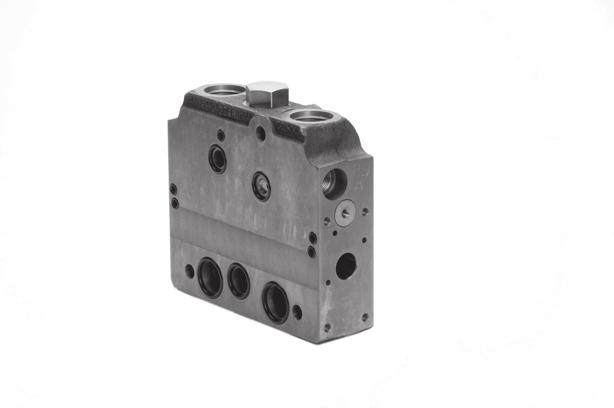
11 Modules and code numbers PVP 100 ACCESSORIES FOR PUMP SIDE MODULES Symbol Description Code number Dummy spool 155G5041* 12 V 155G5052* PVPE electrically actuated unloading valve. Normally open solenoid valve 24 V 155G5054* 12 V 161B5052 PVPP electrically actuated pilot shut off. Normally closed solenoid valve 24 V 161B5054 * For PVPF open center inlets only PVB 100 BASIC MODULE Code number Symbol Description PVB Port size Without PVLP With PVLP G 3 /4 161B B6260 Post compensated 1 1 /16-12 UN 161B B6660 Post compensated G 3 /4 161B B6262 With pilot operated check valves on work port A and B 1 1 /16-12 UN 161B B L0720 Rev. B 02/
12 Modules and code numbers PVB 32 BASIC MODULE WITH T0 Symbol Description PVB Code number... No facility for Facility for shock valve for shock valve BSP SAE BSP SAE Without load drop check valve and pressure compensator. Can be used where load holding valves prevent oil from floating back through the channel P Load drop check valve Pre compensated Pre compensated Adjustable LS A/B limiting valves. External LS connection port A/B. Also used for float position spools Connection: A and B-port G 1 /2 [ 7 /8 in - 14] L0720 Rev. B 02/2006
13 Modules and code numbers PVBZ 32 BASIC MODULE Symbol Description PVBZ Without thermal relief valve... BSP SAE With thermal relief valve... BSP SAE Without compensator and load drop check valve With pilot operated check valves on work port B Max. work port pressure = 210 bar [3045 psi] Without compensator and load drop check valve With pilot operated check valves on work port A and B Max. work port pressure = 210 bar [3045 psi] Pre compensated With pilot operated check valves on work port B Compensated work port flow A/B = 100 l/min [26.4 US gal/min] Max. work port pressure = 210 bar [3045 psi] Pre compensated With pilot operated check valves on work port A and B Compensated work port flow A/B = 100 l/min [26.4 US gal/min] Max. work port pressure = 210 bar [3045 psi] Pre compensated With pilot operated check valves on work port A and B LSA/B shuttle valve for float and shuttle pin Compensated work port flow A/B = 100 l/min [26.4 US gal/min] Max. work port pressure = 210 bar [3045 psi] Connection: A and B-port G 1 /2 [ 7 /8 in - 14] Seal kit for PVBZ L0720 Rev. B 02/2006
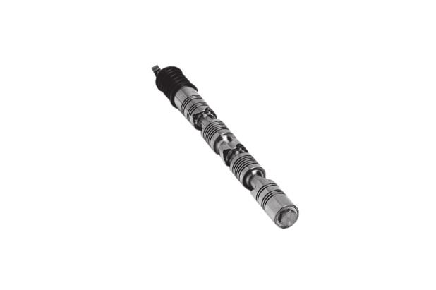
14 Modules and code numbers CODE NUMBERS FOR USE ON PVG PVM Mechanical actuation PVM, Standard, spring centered Individual oil flow adjustment to ports A an B Code number w. stopscrews w/o stop screws PVM Without actuation lever and base Shaft for mounting of actuation lever. PVM A standard, without actuation lever. With base for mounting of actuation lever Code number for the anodized version of 3171 is 3184 PVMD Cover for mechanical actuation PVMD* Cover for purely mechanically operated valve Code number 0001 PVH Hydraulic actuation PVH* G 1 /4 Cover for hydraulic remote control 9 /16-18 UNF Code number PVMR Friction detent PVMR* Friction detent Code number 0015 PVMF Mechanical float position PVMF* Mechanical float position lock, float B-port Code number 0005 * Opposite of the PVM L0720 Rev. B 02/2006
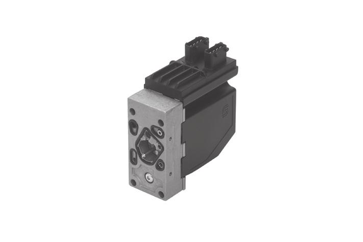
15 Modules and code numbers CODE NUMBERS FOR USE ON PVG PVE for PVG 100 PVEO, ON/OFF actuation Hirschmann AMP Deutsch Code no V 24 V 12 V 24 V 12 V 24 V ON/OFF PVEO ON/OFF with ramp Hirschmann AMP Deutsch PVEA/PVEH/PVES, proportional actuation connector connector connector Code no V V V PVEA Standard, active fault monitoring Not available Standard, passive fault monitoring Not available PVEA-DI Standard, active fault monitoring Not available Standard, passive fault monitoring Not available PVEH Standard, active fault monitoring Standard, passive fault monitoring PVEH-F Float, active fault monitoring Not available PVEH-DI Standard, active fault monitoring Not available Standard, passive fault monitoring Not available PVEP Standard, active fault monitoring PVEP-F Standard, active fault monitoring PVES 0% hysteresis, active fault monitoring % hysteresis, passive fault monitoring PVED-CC Can-bus interface Not available L0720 Rev. B 02/
16 Modules and code numbers PVLA, SUCTION VALVE (FITTED IN PVB) Symbol Description Code number Suction valve for port A and/or B 2001 Cap for connecting the nonactive port to tank, when using a single acting spool L0720 Rev. B 02/2006
17 Modules and code numbers PVLP, SHOCK AND SUCTION VALVE (FITTED IN PVB) Symbol Description Shock and suction valve for port A and B. (Not adjustable) Setting Code bar [psi] number L0720 Rev. B 02/
18 Modules and code numbers PVT 100 TANK MODULE Symbol Description Port size Code number PVT Without active elements With T-port PVLP shock valve facility G 1 1 /4 1 5 /8 - UN 161B B2520 PVT Without active elements With T-port PVLP shock valve facility With LX connection G 1 /4 [ 9 /16 in 18 UNF G 1 1 /4 1 5 /8 - UN 161B B2525 PVTI 100/32 INTERFACE MODULE Symbol Description Portsize Code number PVTI Without active elements With T-port PVLP shock valve facility G 1 1 /4 1 5 /8 - UN 161B B2220 ASSEMBLY KIT PVG 100 PVSI / PVT Code number 161B. Description 1 PVB 2 PVB 3 PVB 4 PVB 5 PVB 6 PVB 7 PVB 8 PVB Tie bolts and seals ASSEMBLY KIT PVG 100 / PVTI INTERFACE MODULE Code number 161B. Description 1 PVB 2 PVB 3 PVB 4 PVB 5 PVB 6 PVB 7 PVB 8 PVB Tie bolts and seals ASSEMBLY KIT PVB 32 Code number. Description 1 PVB 2 PVB 3 PVB 4 PVB 5 PVB 6 PVB 7 PVB 8 PVB 9 PVB 10 PVB Tie bolts and seals L0720 Rev. B 02/2006
19 Technical characteristics GENERAL The characteristics in this catalog are typical measured results. During measuring a mineral based hydraulic oil with a viscosity of 21 mm 2 /s [102 SUS] at a temperature of 50 C [122 F] was used. PVP, PUMP SIDE MODULE Pressure relief valve characteristic in PVP The pressure relief valve is set at an oil flow of 15 l/min [4.0 US gal/min]. Setting range: 30 to 350 bar [435 to 5075 psi] Neutral flow pressure in PVP, open center OPEN CENTER FLOW RATING As mentioned on page 5, the flow rating of the different main spools will depend on the standby pressure available. In open center systems, the standby pressure equals the pressure drop P->T, see above diagram. A pump flow of 150 l/min led to tank across the pressure adjusting spool, will generate a standby pressure of app. 15 bar (PVP with 12 bar spring). The according main spool flow ratings will correspond to the curves on page 20 For PVPs with a 20 bar spring, the standby pressure available will be 20 bar or higher. Hence the according main spool flow ratings will correspond to page L0720 Rev. B 02/
20 Technical characteristics PVB, BASIC MODULE PVB with pressure compensation, closed center PVP Oil flow as a function of spool travel for spools A to F Set pressure difference between pump pressure and LS signal = 15 bar bar [218 psi] measured at the P-port of the valve. For spool size reference see page 30 and 31. PVB with pressure compensation, closed center PVP Oil flow as a function of spool travel for spools A to F Set pressure difference between pump pressure and LS signal = 20 bar bar [290 psi] measured at the P-port of the valve. For spool size reference see page 30 and L0720 Rev. B 02/2006
21 Technical characteristics PVB, BASIC MODULE (CONTINUED) Oil flow at LS pressure limiting, pressure compensated PVB for spools A, C and E Oil flow at LS pressure limiting, pressure compensated PVB for spools B, D and F 520L0720 Rev. B 02/
22 Technical characteristics PVLP, SHOCK AND SUCTION VALVE PVLP, shock valve PVLP is set at an oil flow of 10 l/min [2.6 US gal/min]. The shock valve PVLP is designed to absorb shock effects. Consequently, it should not be used as a pressure relief valve. PVLA, SUCTION VALVE PVLP/PVLA, suction valve L0720 Rev. B 02/2006
23 Dimensions VALVE DIMENSION, PVG 100, OPEN CENTER PVPF Pp accumulator connection : G 1 /4 [ 9 /16 in - 18 UNF] LS connection : G 1 /4 [ 9 /16 in - 18 UNF] P gage connection : G 1 /4 [ 9 /16 in - 18 UNF] T0 port connection : G 1 /4 [ 9 /16 in - 18 UNF] Pp gage connection : G 1 /4 [ 9 /16 in - 18 UNF] P: Pump port connection; G1 [1 5 /16 in - 12 UNF] G: PVPE unloading valve F : Tank port connection; G 1 1 /4 [1 5 /8 in - 12 UNF] H: PVPP pilot shut off valve J : Mounting thread; M12 x 14 mm deep. It is recommended ton only use 3 of 4 mounting holes provided. K : LX connection : G 1 /4 [ 9 /16 in - 18 UNF] L : LS relief valve 1 PVB 2 PVB 3 PVB 4 PVB 5 PVB 6 PVB 7 PVB 8 PVB L 1 L 2 mm [in] [3.15] [5.04] [6.93] [8.82] [10.71] [12.60] [14.49] [16.38] mm [in] [6.93] [8.82] [10.71] [12.60] [14.49] [16.38] [18.27] [20.16] 520L0720 Rev. B 02/
24 Dimensions VALVE DIMENSION PVG 100/32, CLOSED CENTER PVPV LS connection : G 1 /4 [ 9 /16 in - 18 UNF] P gage connection : G 1 /4 [ 9 /16 in - 18 UNF] T0 port connection : G 1 /4 [ 9 /16 in - 18 UNF] Pp gage connection : G 1 /4 [ 9 /16 in - 18 UNF] Pp accumulator connection : G 1 /4 [ 9 /16 in - 18 UNF] D : Pump port connection; G1 [1 5 /16 in - 12 UNF] E : Port A and B PVB 100; G 3 /4 [1 1 /16 in - 12 UNF] F : Tank port connection; G1 1 /4 [1 5 /8 in - 12 UNF] H : Port A and B PVB 32; G 1 /2 [ 7 /8 in - 14 UNF] I : Mounting thread ; M8 x 15 mm deep [ 5 /16 in - 18 UNC] J : Mounting thread; M12 x 14 mm deep L : LS relief valve 1 PVB 2 PVB 3 PVB 4 PVB 5 PVB 6 PVB 7 PVB 8 PVB 9 PVB 10 PVB L 1 mm [in] [3.15] [5.04] [6.93] [8.82] [10.71] [12.60] [14.49] [16..38] - - L 2 mm [in] [3.94] [5.83] [7.72] [9.61] [11.50] [.39] [15.28] [17.16] [19.05] [20.94] L 3 mm [in] - [9.64] [11.54] [.43] [15.31] [17.20] [19.09] [20.98] [22.87] [24.76] It is recommended not to exceed 10 PVB 100/32 in a valve group L0720 Rev. B 02/2006
25 Dimensions VALVE DIMENSION PVG 100, CLOSED CENTER PVP WITH INTEGRATED PRIORITY VALVE CF connection : G 1 /2 [ 3 /4 in - 16 UNF] LS connection : G 1 /4 [ 9 /16 in - 18 UNF] P gage connection : G 1 /4 [ 7 /16 in - 24 UNF] T0 port connection : G 1 /4 [ 9 /16 in - 18 UNF] Pp gage connection : G 1 /4 [ 7 /16 in - 24 UNF] P pump port connection; G 3 /4 [1 1 /16 in - 12 UNF] Lst: LS connection for steering unit; G 1 /4 [ 9 /16 in - 18 UNF] E : Port A and B PVB 100; G3/4 [1 1 /16 in - 12 UNF] H : Mounting thread : M12 x 14 mm deep J : Mounting bracket with holes for M12 screws K : LX connection : G 1 /4 [ 9 /16 in - 18 UNF] M : LS relief valve F : G 1 /4 [1 1 /16 in] 2 1 PVB 2 PVB 3 PVB 4 PVB 5 PVB 6 PVB 7 PVB 8 PVB L 1 mm [in] [5.51] [5.12] [9.29] [11.18] [9.] [14.96] [16.85] [18.74] L 2 mm [in] [7.80] [9.69] [11.57] [.46] [15.35] [17.24] [19.] [21.02] 520L0720 Rev. B 02/
26 Dimensions GENERAL DIMENSIONS L0720 Rev. B 02/2006
27 Hydraulic systems ELECTRICALLY ACTUATED PVG 100 VARIABLE DISPLACEMENT PUMP PRIORITY FUNCTION, PVB 100 WITH INTEGRATED PILOT OPERATED CHECK VALVES ELECTRICALLY ACTUATED PVG 100/32 FIXED DISPLACEMENT PUMP PVB 100/32 WITH INTEGRATED PILOT OPERATED CHECK VALVES 520L0720 Rev. B 02/
28 Other operating conditions OIL The main duty of the oil in a hydraulic system is to transfer energy; but it must also lubricate the moving parts in hydraulic components, protect them against corrosion, and transport dirt particles and heat out of the system. It is therefore important to choose the correct oil with the correct additives. This gives normal operation and long working life. Mineral oil For systems with PVG 100 valves Sauer-Danfoss recommends the use of mineral-based hydraulic oil containing additives: Type HLP (DIN 51524) or HM (ISO 6743/4). Non-flammable fluids Phosphate-esters (HFDR fluids) can be used without special precautions. However, dynamic seals must be replaced with FPM (Viton) seals. So please contact the Sauer-Danfoss Sales Organization if the PVG 100 valve is to be used with phosphate-esters. The following fluids should only be used according to agreement with the Sales Organization for Sauer-Danfoss: Water-glycol mixtures (HFC fluids) Water-oil emulsions (HFB fluids) Oil-water emulsions (HFAE fluids) Biodegradable oils PVG 100 valves can be used in systems with rapeseed oil. The use of rapeseed oil is conditioned by - complying with the demands on viscosity, water content, temperature and filtering etc. (see chapters below and technical data page 7). - adapting the operating conditions to the directions of the oil supplier. Before using other biodegradable fluids, please consult the Sauer-Danfoss Organization. PARTICLE CONTENT, DEGREE OF CONTAMINATION Oil filtration must prevent particle content from exceeding an acceptable level, i.e. an acceptable degree of contamination. Maximum contamination for PVG 100 is 23/19/16 (see ISO Calibration in accordance with the ACFTD method). In our experience a degree of contamination of 23/19/16 can be maintained by using a filter fineness as described in the next section L0720 Rev. B 02/2006
29 Other operating conditions FILTRATION Effective filtration is the most important precondition in ensuring that a hydraulic system performs reliably and has a long working life. Filter manufacturers issue instructions and recommendations. It is advisable to follow them. System filters Where demands on safety and reliability are very high a pressure filter with bypass and indicator is recommended. Experience shows that a 10 µm nominal filter (or finer) or a 20 µm absolute filter (or finer) is suitable. It is our experience that a return filter is adequate in a purely mechanically operated valve system. The fineness of a pressure filter must be selected as described by the filter manufacturer so that a particle level of 23/19/16 is not exceeded. The filter must be fitted with pressure gauge or dirt indicator to make it possible to check the condition of the filter. In systems with differential cylinders or accumulators the return filter must be sized to suit the max. return oil flow. Pressure filters must be fitted to suit max. pump oil flow. Internal filters The filters built into PVG 100 are not intended to filter the system but to protect important components against large particles. Such particles can appear in the system as a result of pump damage, hose fracture, use of quick-couplings, filter damage, starting up, contamination, etc. The filter in the electrical actuator PVE protecting the solenoid valves has a mesh of 150 µm. Bursting pressure drop for internal filters is 25 bar [360 psi]. 520L0720 Rev. B 02/
30 Modules and code numbers STANDARD SPOOLS (ELECTRICAL AND MECHANICAL ACTUATION) Code number 161B... Pressure compensated flow l/min [US gal/min] Symbol A 40 [10,6] B 65 [17,2] C 100 [26,4] D 0 [34,4] E 150 [39.6] F 180 [47,6] way, 3-position Closed neutral position way, 3-position Throttled, open neutral position 4-way, 4-position Closed neutral position Float P B F Main spools for PVG 32, see catalog, 520L STANDARD SPOOLS (HYDRAULIC ACTUATION) Code number 161B... Symbol A 40 [10,6] Pressure compensated flow l/min [US gal/min] B C D E [17,2] [26,4] [34,4] [39.6] F 180 [47,6] way, 3-position Closed neutral position way, 3-position Throttled, open neutral position L0720 Rev. B 02/2006
31 Modules and code numbers SPOOLS FOR FRICTION DETENT PVMR Code number 161B... Symbol A 40 [10,6] Pressure compensated flow l/min [US gal/min] B C D E [17,2] [26,4] [34,4] [39.6] F 180 [47,6] way, 3-position Throttled, open neutral position PVMR friction detent is designed for motor spools only. SPOOLS FOR MECHANICAL FLOAT POSITION PVMF Code number 161B... Symbol A 40 [10,6] Pressure compensated flow l/min [US gal/min] B C D E [17,2] [26,4] [34,4] [39.6] F 180 [47,6] 4-way, 4-position Closed neutral position Float P B F Spools for PVB 32, see catalog DKMH.570.C L0344 Spools for PVBZ 32, see Tech Note DKMH.PN.570.N L L0720 Rev. B 02/
32 Module selection chart PVB, basic module Code no. 161B No facilities for shock valves A and B Facilities for shock valves A and B G 3 /4 1 /16 in-14 G 3 /4 1 /16 in-14 Without pilot operated check valve With pilot operated check valve Weight kg [lb] 5.5 kg [12. lb] PVM, mechanical actuation Code no.... With stop Without screw stop screw Standard 3171* Standard, with base, without arm and button Standard, without base, arm and button Weight kg [lb] 0.4 [0.9] * Anodized 3184 PVPC (for details see catalog, 520L0344) Code no. G 1 /4 9 /16 in - Weight 18 UNF kg [lb] External pilot supply External pilot supply incl. check valve Not available for PVPV 5211 and 5611 PVTI 100/32 interface module Code no. 161B BSP SAE PVTI, with T-port and PVLP facility T- connection G 1 1 /4 [1 5 /8 UN] Tank module, PVT Code no. 161B BSP SAE PVT, with T-port and PVLP facility PVT, with LX connection, T-port and PVLP facility T- connection G 1 1 /4 [1 5 /8 UN] Weight kg [lb] [19.18] kg Weight [lb] 6.3 kg [.89] Assembly kit PVG 100 / PVSI / PVPT Code number 161B. Description 1 PVB 2 PVB 3 PVB 4 PVB 5 PVB 6 PVB 7 PVB 8 PVB Tie bolts and seals Assembly kit PVG 100 / PVTI interface module Code number 161B. Description 1 PVB 2 PVB 3 PVB 4 PVB 5 PVB 6 PVB 7 PVB 8 PVB Tie bolts and seals Assembly kit PVB 32 Description Code number... 1 PVB 2 PVB 3 PVB 4 PVB 5 PVB 6 PVB 7 PVB 8 PVB 9 PVB 10 PVB PVB s Weight [kg [lb] 0.1 [0.2] 0.15 [0.3] 0.25 [0.6] 0.30 [0.7] 0.40 [0.9] 0.45 [1.0] 0.50 [1.1] 0.60 [1.3] 0.65 [1.4] 0.70 [1.6] PVLP, shock/and anti-cavitation valves Code no Settings bar [psi] Weight [kg [lb] 0.05 kg [0.17 lb] L0720 Rev. B 02/2006
33 Module selection chart PVP 100, pump side module Closed center, PVPV Open center, PVPF With pilot supply With pilot supply Code no. 161B for PVE for PVE for PVE. for PVE for PVE and facility for With integrated and facility for pilot shut off priority function pilot shut off 12 bar 20 bar 12 bar 20 bar P-port = G P-port = 1 5 /16 UN P-port = G 3 /4 T-port = G P-port = G 1 1 /16 UN T -port = 1 5 /16 UN Weight kg [lb] 8.5 kg [12.30 lb] Accessory moduls for PVP 100 Code no. Weight kg lb Plug, PVPD 155G5041* 0.4 [0.9] Elec. unloading 12 V 155G5052* valve, PVPE 24 V 155G5054* 0.7 [1.1] Pilot shut off 12 V 161B5052 valve, PVPP 24 V 161B [0.7] * For PVPF only PVE, electrical actuation PVMD, PVH, PVMR, PVMF covers Code no. Code No. Weight kg [lb] Cover for PVM Hydraulic actuation PVH G 1 /4 Hydraulic actuation PVH /16-18 UNF PVMR (frict. detent) PVMF (mech. float position) L0720 Rev. B 02/2006 Code no. PVEO, on-off PVEO-R, on/off Code No. Weight Hirsch AMP Deutsch kg [lb] 12 V [1.3] 24 V [1.3] 12 V [1.3] 24 V [1.3] PVEA, active fault mon [2.0] PVEA, passive fault mon [2.0] PVEA-DI, active fault mon [2.0] PVEA-DI, passive fault mon [2.0] PVEH active fault mon [2.2] PVEH passive fault mon [2.2] PVEH-F float pos. act. fault [2.2] PVEH- DI active fault mon [2.2] PVEH - DI passive fault mon [2.2] PVEP active fault mon [2.2] PVEP-F float pos. act. fault [2.2] PVES, active fault mon [2.2] PVES, passive fault mon [2.2] PVED-CC, Can-bus interface [2.2] PVLA, anti-cavitation valve Code no. Code No. Weight kg [lb] Plug A or B Valve A or B
34 Order specification ORDER SPECIFICATION An order form for Saue-Danfoss PVG 100 hydraulic valve is shown on the next page. The form can be obtained from the Sauer-Danfoss Sales Organization. Both the module selection chart on the previous pages and the order form are divided into fields 0, 1-10, 11, 12,, a, b, and c. Each module has its own field: 0: Pump side module PVP Plug for external pilot oil supply PVPC Electrical unloading valve PVPE Electrical pilot shut off valve PVPE 1-10: Basic valves PVB : Main spool PVBS a: Mechanical actuator PVM c: Cover for mechanical actuation PVMD Cover for hydraulic actuation PVH Electrical actuators PVE b: Shock and suction valve PVLP Suction valve PVLA 11: End plate PVSI Tank module PVT Interface module PVTI 12: Assembly kit PVAS Please state - Code numbers of all modules required - Required setting (P) for pump side module Standard and option assembly The PVG 100 valve group is assembled the way the module selection chart shows if the code number for PVM is written in field a, and the code number for PVMD, PVE or PVH in field c. The valve group is assembled so that the mechanical actuator is mounted on the opposite end of the basic module, if the code number for PVM is written in field c of the order form and the code numbers for PVMD, PVE or PVH in field a. Reordering The space at the top right-hand corner of the form is for Sauer-Danfoss to fill in. The code number for the whole of the specified valve group (PVG No.) is entered here. In the event of a repeat order all you have to do is enter the number Sauer-Danfoss has given on the initial confirmation of order L0720 Rev. B 02/2006
35 Specification sheet Subsidiary/Dealer PVG No. Customer Customer No. Application Revision No. Function A-Port O 161B B-Port p = bar a 1 c b LS A bar LS B bar b a 2 c b LS A bar LS B bar b a 3 c b LS A bar LS B bar b a 4 c b LS A bar LS B bar b a 5 c b LS A bar LS B bar b a 6 c b LS A bar LS B bar b a 7 c b LS A bar LS B bar b a 8 c b LS A bar LS B bar b a 9 c b LS A bar LS B bar b a 10 c b LS A bar LS B bar b Remarks Filled in by Date 520L0720 Rev. B 02/
36 Specification sheet Subsidiary/Dealer PVG No. Customer Customer No. Application Revision No. Function A-Port O 161B B-Port p = psi a 1 c b LS A psi LS B psi b a 2 c b LS A psi LS B psi b a 3 c b LS A psi LS B psi b a 4 c b LS A psi LS B v b a 5 c b LS A psi LS B psi b a 6 c b LS A psi LS B psi b a 7 c b LS A psi LS B psi b a 8 c b LS A psi LS B psi b a 9 c b LS A psi LS B psi b a 10 c b LS A psi LS B psi b Remarks Filled in by Date L0720 Rev. B 02/2006
37 Notes 520L0720 Rev. B 02/
38 Notes L0720 Rev. B 02/2006
39 Notes 520L0720 Rev. B 02/
40 OUR PRODUCTS Hydrostatic transmissions Hydraulic power steering Electric power steering Electrohydraulic power steering Closed and open circuit axial piston pumps and motors Gear pumps and motors Bent axis motors Orbital motors Transit mixer drives Planetary compact gears Proportional valves Directional spool valves Cartridge valves Hydraulic integrated circuits Hydrostatic transaxles Integrated systems Fan drive systems Electrohydraulics Microcontrollers and software Electric motors and inverters Joysticks and control handles Displays Sensors Sauer-Danfoss Mobile Power and Control Systems Market Leaders Worldwide Sauer-Danfoss is a comprehensive supplier providing complete systems to the global mobile market. Sauer-Danfoss serves markets such as agriculture, construction, road building, material handling, municipal, forestry, turf care, and many others. We offer our customers optimum solutions for their needs and develop new products and systems in close cooperation and partnership with them. Sauer-Danfoss specializes in integrating a full range of system components to provide vehicle designers with the most advanced total system design. Sauer-Danfoss provides comprehensive worldwide service for its products through an extensive network of Authorized Service Centers strategically located in all parts of the world. Sauer-Danfoss (US) Company 2800 East th Street Ames, IA 50010, USA Phone: , Fax: Sauer-Danfoss (Neumünster) GmbH & Co. OHG Postfach 2460, D Neumünster Krokamp 35, D Neumünster, Germany Phone: , Fax: Sauer-Danfoss ApS DK-6430 Nordborg, Denmark Phone: , Fax: L0720 Rev. B 02/2006
Phased Out Products. Proportional Valve Group PVG 83. Tech Note MAKING MODERN LIVING POSSIBLE
 MAKING MODERN LIVING POSSIBLE Tech Note Proportional Valve Group PVG 83 Valve system PVG 83 is a hydraulic load sensing valve designed to give the customer just the valve he needs. From a simple load sensing
PVG 120 Proportional Valves. Specifications
 PVG 120 Proportional Valves s Ordering guidance and remote control units ORDERING GUIDANCE The module selection chart and the order form are both divided into fields. Each module has its own field: 0:
PVG 120 Proportional Valves. Service Parts Manual
 PVG 120 Proportional Valves Service Parts Manual Contents and Data Survey CONTENTS AND DATA SURVEY Page Sectional drawing... 3 Identification...4 Installation PVG... 5 Spare parts... 22 Pos. 1: PVP, pump
Proportional Valve Group PVG 100
 Technical Information Proportional Valve Group PVG 100 www.danfoss.com Revision history Table of revisions Date Changed Rev May 2018 minor edits 0502 March 2016 Updated for Engineering Tomorrow design.
Proportional Valve Group PVG 100
 MAKING MODERN LIVING POSSIBLE Technical Information Proportional Valve Group PVG 1 powersolutions.danfoss.com Revision History Table of Revisions Date Changed Rev Jan 214 Converted to Danfoss layout DITA
PVG 32 PROPORTIONAL VALVE Sauer TECHNICAL INFORMATION AND OTHER OPERATING CONDITIONS
 Sauer TECHNICAL INFORMATION AND OTHER OPERATING CONDITIONS Effective filtration is the most important precondition in ensuring that a hydraulic system performs reliably and has a long working life. Filter
PVG 120 Proportional Valves. Technical Information
 PVG 120 Proportional Valves Technical Information Contents CONTENTS General...3 Function...5 Hydraulic systems...7 Technical data...9 Electrical actuation... 12 Modules and code numbers... 16 PVP, pump
PVG 32 Proportional Valves. Technical Information
 PVG 32 Proportional Valves Technical Information Contents CONTENTS Page General...3 Function...5 PVG 32 valve group...5 PVPC, plug for external pilot oil supply...7 PVMR, friction detent...9 PVMF, mechanical
Proportional Valve Group PVG 120
 MAKING MODERN LIVING POSSIBLE Specification Proportional Valve Group PVG 120 powersolutions.danfoss.com Revision history Table of revisions Date Changed Rev May 2014 Converted to Danfoss layout DITA CMS
Proportional Valve Group PVG 128/256
 Service and Parts Manual Proportional Valve Group powersolutions.danfoss.com Revision history Table of revisions Date Changed Rev July 207 First edition 00 2 Danfoss July 207 AX00000346en-US00 Contents
PVG 32 Proportional Valves. Technical Information
 PVG 32 Proportional Valves Technical Information Contents general Function Technical data General...4 Function...7 PVG 32 valve group...7 PVPC, plug for external pilot oil supply...9 PVMR, friction detent...
Hydrau Hyd. ydr ique. Hydraulics. Hydraulik H. Hydraulics. aulique aulik q ue. Hydraulique. ulique. Hydraulique. Hydraulique Hydraulik.
 Catalogue Load-independent Proportional valve Type PVG 32 With mechanical actuation With electric remote control and mechanical actuation With hydraulic remote control and mechanical actuation ydr ique
PVG 120 Proportional Valves. Technical Information
 PVG 120 Proportional Valves Technical Information Contents Revision History Contents Function Hydraulic Systems Technical Data Electrical Actuation Modul and Code Numbers Technical Characteristics Dimensions
PVG 32 Proportional Valve Group
 Technical Information PVG 32 Proportional Valve Group www.danfoss.com Revision history Table of revisions Date Changed Rev December 218 Major revision of document. 111 September 218 Safety topic, new PVBS
Proportional Valve Group PVG 120
 Technical Information Proportional Valve Group PVG 120 powersolutions.danfoss.com Revision history Table of revisions Date Changed Rev March 2017 minor updates 1002 Mar 2014 Chapters re-order, Modules
Proportional Valve Group PVG 16/32/128/256
 Service and Parts Manual Proportional Valve Group www.danfoss.com Revision history Table of revisions Date Changed Rev October 208 Combined installation guides, service and parts manuals 00 2 Danfoss October
Directional Control Valve Model Technical Information. Phased Out OUT BASE BKT CYL ROD
 BASE BKT CYL ROD OUT IN Directional Control Valve Model 1480 Technical Information History of Revisions Revisions Table of Revisions Date Page Changed Rev. May 2008 - first edition AA 2008 Sauer-Danfoss.
Hydraulics. Hydraulik
 Catalogue Load-independent Proportional Valve Type PVG 120 With mechanical actuation With electrical remote control and mechanical actuation With hydraulic remote control and mechanical actuation ulics
Proportional Valve Group PVG 16
 MAKING MODERN LIVING POSSIBLE Technical Information Proportional Valve Group PVG 16 powersolutions.danfoss.com Revision History Table of Revisions Date Changed Rev Jan 2014 Converted to Danfoss layout
PVG 120 Proportional Valves. Technical Information
 PVG 120 Proportional Valves Technical Information Revision History, Contents Table of Revisions Date Page Changed Rev Apr 2010 Various Layout, drawings and others HA Sep 2010 29, 44 Drawing, new back cover
PVG 16 Proportional Valve Group. Technical Information
 PVG 16 Proportional Valve Group Revisions, Literature Reference Revision History Table of revisions Date Page Changed Rev Oct 2012 - New edition. AA Feb 2013 All Major update BA Literature Reference Literature
PVG 16 Proportional Valve Group. Technical Information
 PVG 16 Proportional Valve Group Revisions, Literature Reference Revision History Table of revisions Date Page Changed Rev Oct 2012 - New edition. AA Literature Reference Literature reference for PVG products
Proportional Valve Group PVG 120
 MAKING MODERN LIVING POSSIBLE Service Manual Proportional Valve Group PVG 120 powersolutions.danfoss.com Revision history Table of revisions Date Changed Rev May 2014 Converted to Danfoss layout DITA CMS,
PVG 32 Specification Sheet. Subsidiary/Dealer. Customer. Application B-Port. B-Port. Subsidiary/Dealer PVG No.
 Remarks BPort PHYDPVG323 PVG 32 Proportional Valves s Subsidiary/Dealer PVG No. Customer Customer No. Appliation Revision No. Funtion APort PVG 32 Sheet Subsidiary/Dealer PVG No. Customer Customer No.
OMEW Standard and with Low Speed Option. Orbital Motors. Technical Information
 Standard and with Low Speed Option Orbital Motors Technical Information Contents Revision History Table of Revisions Date Page Changed Rev Jan 2009 Many major change BA Mar 2010 16 Japan location BB Contents
Series TMM Axial Piston Motor. Technical Information
 Series TMM Axial Piston Motor Technical Information General Description GENERAL DESCRIPTION These motors are designed primarily to be combined with other products in closed circuit systems to transfer
Proportional Valve Group PVG 16
 Technical Information Proportional Valve Group PVG 16 powersolutions.danfoss.com Revision history Table of revisions Date Changed Rev March 2016 Minor update in PVHC technical characteristics 0303 March
OSPB, OSPC, OSPR, OSPD Open Center Steering units OSPB Closed Center Steering units TAD Torque amplifiers. Technical Information
 OSPB, OSPC, OSPR, OSPD Open Center Steering units OSPB Closed Center Steering units TAD Torque amplifiers Technical Information A wide range of steering components A WIDE RANGE OF STEERING COMPONENTS F300599
Proportional Valve Group PVG 16
 Technical Information Proportional Valve Group PVG 16 powersolutions.danfoss.com Revision history Table of revisions Date Changed Rev February 2017 Major update. 0401 March 2016 Minor update in PVHC technical
Proportional Valve Group PVG 32
 MAKING MODERN LIVING POSSIBLE Technical Information Proportional Valve Group PVG 32 powersolutions.danfoss.com Revision history Table of revisions Date Changed Rev August 2015 PVPX modules description
Series 20 Axial Piston Pumps. Technical Information
 Series 20 Axial Piston Pumps Technical Information General Description INTRODUCTION Sauer-Danfoss a world leader in hydraulic power systems has developed a family of axial piston pumps. DESCRIPTION Sauer-Danfoss
Series 20 Axial Piston Pumps. Technical Information
 Series 20 Axial Piston Pumps Technical Information General Description INTRODUCTION Sauer-Danfoss a world leader in hydraulic power systems has developed a family of axial piston pumps. DESCRIPTION Sauer-Danfoss
Proportional Valve Group PVG 32
 MAKING MODERN LIVING POSSIBLE Technical Information Proportional Valve Group PVG 32 powersolutions.danfoss.com Revision History Table of Revisions Date Changed Rev Feb 214 Spec. sheet update HE Jan 214
OMR Technical Information Versions
 Versions Versions Mounting flange Spigot diam,eter (front /rear end) Bolt circle diameter (BC) Shaft Port size European version US version Side port version End port version Flange port version Standard
Directional Control Valve
 Directional Control Valve Service and Parts Manual powersolutions.danfoss.com Directional Control Valves Service and Parts Manual: Contents SERVICE PARTS Inlet cover... 3-4 Outlet cover... 5-6 Standard
OML and OMM Orbital motors. Technical Information
 OML and OMM Orbital motors Technical Information OML and OMM A wide range of orbital motors F300030.TIF A WIDE RANGE OF ORBITAL MOTORS Sauer-Danfoss is a world leader within production of low speed orbital
Series 20 Axial Piston Motors. Technical Information
 Series 20 xial Piston Motors Technical Information General Description INTRODUCTION Sauer-Danfoss a world leader in hydraulic power systems has developed a family of axial piston motors. DESCRIPTION Sauer-Danfoss
Orbital Motors Type OMP, OMR and OMH. Technical Information
 Orbital Motors Type OMP, OMR and OMH Technical Information OMP, OMR and OMH A Wide Range of Hydraulics Motors F 301 245 A Wide Range of Hydraulic Motors Sauer-Danfoss is a world leader within production
Series 20 Axial Piston Motors. Technical Information
 Series 20 xial Piston Motors Technical Information General Description INTRODUCTION Sauer-Danfoss a world leader in hydraulic power systems has developed a family of axial piston motors. DESCRIPTION Sauer-Danfoss
POWER SYSTEM MODE STATUS
 SX Generic Anti Spin Valve Control System System Description 7,7 POWER SYSTEM MODE STATUS 60, 8, 8, 0 9 0, 0, AMP Stecker AMP Connector 8 9 SX Generic Anti Spin Valve Control System Overview DESCRIPTION
Hydrostatic Steering Unit Type OSPB, OSPC and OSPF. Service Manual
 Hydrostatic Steering Unit Type OSPB, OSPC and OSPF Table of Contens Revision History Table of Revisions Date Page Changed Rev Dec 2008 26 Tightening torque changed BC Table of contens... 2 Exploded view
Series 40 M25 Axial Piston Pump. Service Parts Manual
 Series 40 M25 Axial Piston Pump Service Parts Manual 1996, 2004 Sauer-Danfoss. All rights reserved. Printed in U.S.A. Sauer-Danfoss accepts no responsibility for possible errors in catalogs, brochures
OSPB, OSPC, OSPF, OSPD, OSPQ, OSPL Load Sensing Steering Units. OLS Priority Valves. OSQ Flow Amplifiers. Technical Information
 OSPB, OSPC, OSPF, OSPD, OSPQ, OSPL Load Sensing Steering Units OLS Priority Valves OSQ Flow Amplifiers Technical Information A Wide Range of Steering Components Revision History Table of Revisions Date
Series cc Axial Piston Motor. Parts Manual
 Series 90 130 cc Axial Piston Motor 2007 Sauer-Danfoss. All rights reserved. Sauer-Danfoss accepts no responsibility for possible errors in catalogs, brochures and other printed material. Sauer-Danfoss
PVG 32 Metric Ports. Technical Information
 PVG 32 Metric Ports Technical Information T Revisions Revision History Table of Revisions Date Page Changed Rev Dec 2010 40 New back cover C Mar 2012 ll Layout changes, and change in the table, page 21.
POWER SYSTEM MODE STATUS
 SX NFPE Control System System Description 4, 60,2 8, 8, 0 9 0 2, 0, AMP Stecker AMP Connector 4 28 29 42 Overview DESCRIPTION The Sauer-Danfoss NFPE (Non-Feedback Proportional Electric) System for Automotive
OSPB, OSPC, OSPF, OSPD, OSPQ, OSPL Load Sensing Steering Units. OLS Priority Valves. OSQ Flow Amplifiers. Technical Information
 OSPB, OSPC, OSPF, OSPD, OSPQ, OSPL Load Sensing Steering Units OLS Priority Valves OSQ Flow Amplifiers Technical Information A Wide Range of Steering Components Revision History Table of Revisions Date
DH Technical Information. Versions. Versions
 Versions Versions Mounting flange Shaft Port size European version US version Side port version End port version Flange port version Standard shaft seal High pressure shaft seal Drain connection Check
Mobile solutions for aerial lifts
 Mobile solutions for aerial lifts The Sauer-Danfoss system development phase model: inquiry Project specification Concept phase Detailed project plan Technical system specifications Different system proposals
MAKING MODERN LIVING POSSIBLE. Technical Information. Orbital Motors TMVW. powersolutions.danfoss.com
 MAKING MODERN LIVING POSSIBLE Orbital Motors TMVW powersolutions.danfoss.com Revision history Table of revisions Date Changed Rev September 2015 New curve for permissible shaft load 0201 November 2014
OSPB, OSPC, OSPF, OSPD, OSPQ, OSPL Load Sensing Steering Units. OLS Priority Valves. OSQ Flow Amplifiers. Technical Information
 OSPB, OSPC, OSPF, OSPD, OSPQ, OSPL Load Sensing Steering Units OLS Priority Valves OSQ Flow Amplifiers Technical Information A Wide Range of Steering Components Revision History Table of Revisions Date
60+ countries served by our global manufacturing facilities ensures market proximity
 Power and control for all your work function needs Series 45 Open Circuit Axial Piston Pumps 60+ countries served by our global manufacturing facilities ensures market proximity powersolutions.danfoss.com
Steering Valve EHPS and EHPS with OLS 320
 Service Manual Steering Valve EHPS and EHPS with OLS 320 powersolutions.danfoss.com Revision history Table of revisions Date Changed Rev July 2016 Updated EHPS spare parts list 0102 June 2015 First version
Technical Information Series 45 G Frame powersolutions.danfoss.com
 MAKING MODERN LIVING POSSIBLE Technical Information Series 45 G Frame powersolutions.danfoss.com Contents Frame G Design... 4 Specifications... 5 Performance G74B... 6 Performance G9C... 7 Order code...
Technical Information Orbital Motors DH and DS powersolutions.danfoss.com
 MAKING MODERN LIVING POSSIBLE Technical Information Orbital Motors DH and DS powersolutions.danfoss.com and DS F 301 245 A Wide Range of Orbital Motors Danfoss Power Solutions is a world leader within
Steering Priority Valve OLS 160
 MAKING MODERN LIVING POSSIBLE Service Manual Steering Priority Valve OLS 160 powersolutions.danfoss.com Revision History Table of Revisions Date Changed Rev Mar 2014 Converted to Danfoss layout - DITA
Technical Information. Steering Unit OSPU. powersolutions.danfoss.com
 Technical Information Steering Unit OSPU powersolutions.danfoss.com Revision history Table of revisions Date Changed Rev March 2016 Updated to Engineering Tomorrow design 0202 May 2014 Converted to Danfoss
Flow sharing control block in mono block / sandwich plate design M6-15
 Flow sharing control block in mono block / sandwich plate design M6-15 RE 64321 Edition: 01.2015 Replaces: 05.2012 Size 15 Series 3X Maximum operating pressure on pump side 350 bar on consumer side 420
Orbital Motors DH and DS
 MAKING MODERN LIVING POSSIBLE Orbital Motors DH and DS powersolutions.danfoss.com Orbital Motors, DH and DS F 301 245 A Wide Range of Orbital Motors Danfoss Power Solutions is a world leader within production
Flow sharing control block in mono block / sandwich plate design M6-22
 Flow sharing control block in mono block / sandwich plate design M6-22 RE 64322 Edition: 01.2015 Replaces: 05.2012 Size 22 Series 3X Maximum operating pressure on pump side 350 bar on consumer side 420
Efficient performance precise operation. PVG proportional valves
 Efficient performance precise operation. PVG proportional valves Modular system design enables customization for your varying vehicle control needs powersolutions.danfoss.com Flexible, efficient, and global
S5X Shift On The Go (SOTG) Control System. System Description 223,5 82,25 77,75 8,5 8,5 164,5 10,3. AMP Stecker AMP Connector 52,5 POWER SYSTEM MODE
 Control System. System Description 223,5 82,25 77,75 8,5 8,5 164,5 10,3. AMP Stecker AMP Connector 52,5 POWER SYSTEM MODE") SX Shift On The Go (SOTG) Control System System escription 47, POWER SYSTEM 8, 77,7 8, MOE STTUS 8, 0 0 64, 0, MP Stecker MP Connector 4 6 8 4 8, SX Shift On The Go (SOTG) Control System Overview ESCRIPTION
SX Shift On The Go (SOTG) Control System System escription 47, POWER SYSTEM 8, 77,7 8, MOE STTUS 8, 0 0 64, 0, MP Stecker MP Connector 4 6 8 4 8, SX Shift On The Go (SOTG) Control System Overview ESCRIPTION
Distribuíção, revenda emanutenção. CatálogosOnline. (11) (11)
 (11)") Distribuíção, revenda emanutenção CatálogosOnline (11)4174-3300-(11)4765-6775 www.hmc.com.br MAKING MODERN LIVING POSSIBLE Technical Information Axial Piston Pumps Series 20 powersolutions.danfoss.com
Distribuíção, revenda emanutenção CatálogosOnline (11)4174-3300-(11)4765-6775 www.hmc.com.br MAKING MODERN LIVING POSSIBLE Technical Information Axial Piston Pumps Series 20 powersolutions.danfoss.com
H1B Motor Two-Position Control E1, E2
 MAKING MODERN LIVING POSSIBLE Electrical Installation H1B Motor Two-Position Control E1, E2 powersolutions.danfoss.com Revision history Table of revisions Date Changed Rev July 2015 Converted to Danfoss
MCX106A Hall Effect Level Sensor. Technical Information
 MCX106A Hall Effect Level Sensor Technical Information Revisions Revision History Table of Revisions Date Page Changed Rev 21 Jan, 2011 Initial release AA 2011 Sauer-Danfoss. All rights reserved. 2 Sauer-Danfoss
Series ASC Anti Spin Control Valve
 MAKING MODERN LIVING POSSIBLE Technical Information Series ASC Anti Spin Control Valve powersolutions.danfoss.com Revision history Table of revisions Date Changed Rev March 2014 Converted to Danfoss layout
Series 51 Motor Electrohydraulic Two-Position Controls T1, T2
 MAKING MODERN LIVING POSSIBLE Electrical Installation Series 51 Motor Electrohydraulic Two-Position Controls T1, T2 powersolutions.danfoss.com Revision history Table of revisions Date Changed Rev August
Series 51-1 Motor Pressured Compensated Controls TA
 MAKING MODERN LIVING POSSIBLE Series 51-1 Motor Pressured Compensated Controls TA powersolutions.danfoss.com Revision history Table of revisions Date Changed Rev August 2015 Converted to Danfoss layout
Orbital Motors OMEW Standard and with Low Speed Option
 MAKING MODERN LIVING POSSIBLE Technical Information Orbital Motors OMEW Standard and with Low Speed Option powersolutions.danfoss.com Revision history Table of revisions Date Changed Rev October 2014 Changed
H1B Motor Electric Two-Position Control T1, T2
 MAKING MODERN LIVING POSSIBLE Electrical Installation H1B Motor Electric Two-Position Control T1, T2 powersolutions.danfoss.com Revision history Table of revisions Date Changed Rev June 2015 Converted
Series 40 MMF035D and MMV035D Axial Piston Motors. Parts Manual
 Series 40 MMF035D and MMV035D Axial Piston Motors 2003, 2008 Sauer-Danfoss. All rights reserved. 2 520L0602 Rev AA January 2008 Sauer-Danfoss accepts no responsibility for possible errors in catalogs,
H1 Pump Filter Bypass Sensor
 MAKING MODERN LIVING POSSIBLE Electrical Installation H1 Pump Filter Bypass Sensor powersolutions.danfoss.com Revision history Table of revisions Date Changed Rev September 2015 Minor layout revision BC
Post-Compensated Proportional Valve CV2000LS
 www.nimco-controls.com Post-Compensated Proportional Valve CV2000LS Smart Solutions... for the Future Contents Page 5 Page 6 Page 7 Page 8 Page 9 Page 10 Page 11 Page 12 Page 13 Page 14 Page 15 Page 16
OMR, OMR C, and OMRW N Series 5 and 6. Repair Instructions
 , C, and W N Series and Orbital Motors, C and W N Series and Table of Contents Revision View Safety Precautions Date Page Changed Revision 29 Jun, 200 all Changed from Danfoss to Sauer Danfoss lay out
S1X Generic Speed Control System
 MAKING MODERN LIVING POSSIBLE System Description S1X Generic Speed Control System powersolutions.danfoss.com Revision history Table of revisions Date Changed Rev August 2015 Danfoss Layout 0600 September
TMVW Orbital Motors. Technical Information
 Orbital Motors Technical Information A Wide Range of Orbital Motors A Wide Range of Orbital Motors F300030 Tif Sauer-Danfoss is a world leader within production of low speed orbital motors with high torque.
Series 40 MMF044D and MMV044D Axial Piston Motors. Parts Manual
 Series 40 MMF044D and MMV044D Axial Piston Motors 2003, 2008 Sauer-Danfoss. All rights reserved. 2 520L586 Rev AA January 2008 Sauer-Danfoss accepts no responsibility for possible errors in catalogs, brochures
OMP, OMP C, OMPW, and OMPW N Series 7 and 8. Repair Instructions
 , C, W, and W N Series and 8 Orbital Motors, C, and W/N Series and 8 Table of Contents Revision View Safety Precautions Date Page Changed Revision 29 Jun, 200 all Changed from Danfoss to Sauer Danfoss
Electrohydraulic Actuators PVE Series 7
 Service Manual Electrohydraulic Actuators powersolutions.danfoss.com Revision history Table of revisions Date Changed Rev August 017 First edition 0101 Danfoss August 017 AX00000348en-US 0101 Contents
EHPS Steering Valve PVE Actuation Module OSPCX CN Steering Unit
 MAKING MODERN LIVING POSSIBLE Technical Information EHPS Steering Valve PVE Actuation Module OSPCX CN Steering Unit powersolutions.danfoss.com Revision history Table of revisions Date Changed Rev May 2015
Flow sharing control block in sandwich plate design M7-25
 Flow sharing control block in sandwich plate design M7-25 RE 64297 Edition: 07.2016 Replaces: 06.2012 Size 25 Series 3X Maximum working pressure on the pump side 380 bar on the consumer side 420 bar Maximum
OML and OMM Orbital Motors. Repair Instructions
 OML and OMM Orbital Motors Table of Contents, Revision View and Safety Precautions Revision View Date Page Changed Revision Jan 2008 all Changed from Danfoss to Sauer Danfoss lay out AA Mar 2008 13 Service
Steering Unit Type OSPB and OSPC Type ON and CN
 MAKING MODERN LIVING POSSIBLE Service Manual Steering Unit Type OSPB and OSPC Type ON and CN powersolutions.danfoss.com Revision History Table of Revisions Date Changed Rev Mar 2014 Converted to Danfoss
OMT Series 2. Orbital Motors. Service Manual
 OMT Series 2 Orbital Motors Table of Contens, Special Versions Revision History Table of Revisions Date Page Changed Rev Sept 2003 CA Feb 200 4-5 Drain plug updated, Layout adjusted CB Sep 200 6 New back
Sensor Steering Angle Sensor Absolute (SASA)
") MAKING MODERN LIVING POSSIBLE Electrical Installation Sensor (SASA) powersolutions.danfoss.com Revision history Table of revisions Date Changed Rev September 2015 Minor layout revision BB April 2014 Converted
MAKING MODERN LIVING POSSIBLE Electrical Installation Sensor (SASA) powersolutions.danfoss.com Revision history Table of revisions Date Changed Rev September 2015 Minor layout revision BB April 2014 Converted
OMH. Repair Instructions
 OMH Table of Contents Revision View Date Page Changed Revision Jun 2006 New AA Apr 200 6 Japan location AB Sep 200 6 New back cover AC Safety Precautions Always consider safety precautions before beginning
Technical Information Axial Piston Motors Series 20 powersolutions.danfoss.com
 MKING MODERN LIVING POSSILE Technical Information xial Piston Motors Series 20 powersolutions.danfoss.com General Information Introduction Danfoss a world leader in hydraulic power systems has developed
EHPS Steering Valve PVE Actuation Module OSPCX CN Steering Unit. Technical Information
 EHPS Steering Valve PVE Actuation Module OSPCX CN Steering Unit Technical Information A Wide Range of Steering Components Revision History Table of Revisions Date Page Changed Rev Mar 2009 35 Note added
Series cc Axial Piston Motor. Parts Manual
 Series 90 100 cc Axial Piston Motor 2007 Sauer-Danfoss. All rights reserved. Sauer-Danfoss accepts no responsibility for possible errors in catalogs, brochures and other printed material. Sauer-Danfoss
Orbital X Modular Program
 Service Manual Orbital X Modular Program www.danfoss.com Revision history Table of revisions Date Changed Rev May 2018 Updated document with new S-Spring tool and information 0201 Apr 2018 Removed S-Spring
Steering OSPB, OSPC, OSPD Open Center and OSPB Closed Center
 echnical Information Steering OSB, OSC, OSD Open Center and OSB Closed Center powersolutions.danfoss.com evision history able of revisions Date Changed ev April 2016 Updated to Engineering omorrow design
Quick Reference Parts Manual Variable Displacement Motor Series 20, series powersolutions.danfoss.com
 MAKING MODERN LIVING POSSIBLE Quick Reference Parts Manual Variable Displacement Motor Series 20, 20-27 series powersolutions.danfoss.com 2 Contents Service parts Exploded view drawing (20 thru 23 series)...4
Product Reliability Data (MTTF) for S90P
 for S90P") MAKING MODERN LIVING POSSIBLE Functional Safety Product Reliability Data (MTTF) for S90P042-250 powersolutions.danfoss.com Revision history Table of revisions Date Changed Rev May 2015 Added Mission time
MAKING MODERN LIVING POSSIBLE Functional Safety Product Reliability Data (MTTF) for S90P042-250 powersolutions.danfoss.com Revision history Table of revisions Date Changed Rev May 2015 Added Mission time
Faster. Count on availability when you need it most H1B Bent Axis Motors Rapid Delivery Center. time to market. powersolutions.danfoss.
 Count on availability when you need it most H1B Bent Axis Motors Rapid Delivery Center Faster time to market Danfoss RDCs ensure you have the product you want, when you want it powersolutions.danfoss.com
Contents. Directional Control Valve 3 Series CV 452. Page 3-4. General Information. Page 5. Technical data. Page 6. Performance Curves.
 Contents Page 3-4 Page 5 Page 6 Page 7 Page 8 Page 9 Page 10 Page 11 Page 12 Page 13 Page 14 General Information Technical data Performance Curves Dimensions - Basics Valve Dimensions - LS Valve Secondary
VED05MJ - PROPORTIONAL DIRECTIONAL CONTROL VALVES WITH OBE & POSITION FEEDBACK
 CONTINENTAL HYDRAULICS VED05MJ PROPORTIONAL DIRECTIONAL CONTROL VALVES WITH OBE & POSITION FEEDBACK VED05MJ - PROPORTIONAL DIRECTIONAL CONTROL VALVES WITH OBE & POSITION FEEDBACK 5505 WEST 123RD STREET
Sensors KS10201 Microsyn Level Sensor
 MAKING MODERN LIVING POSSIBLE Technical Information Sensors powersolutions.danfoss.com Revision history Table of revisions Date Changed Rev November 2015 Converted to Danfoss layout 0001 August 2010 Initial
Steering unit LAGC. Data sheet
 Steering unit LAGC Data sheet Nominal sizes Series Maximum flow HE 14365 / 09.2017 40 1000 1 x and 2 x 80 l / min 2 LAGC HE 14365 / 09.2017 Page Content 4 4 5 6 7 8 9 10 11 12 13 14 Features Ordering details
2.4 HEAVY DUTY SERIES
 2 2.4 HEAVY DUTY SERIES CONTENTS PPV102 Ordering Code 2.4.1 Heavy Duty Series 2.4.2 Heavy Duty Series compensator 2.4.3 Standard gear pump models Technical Information 2.4.4 Specifications 2.4.5 Hydraulic
Directional Control Valve CV550
 www.nimco-controls.com Directional Control Valve CV550 Smart Solutions... for the Future Contents Page 5 Page 6 Page 7 Page 8 Page 9 Page 10 Page 11 Page 12 Page 13 Page 14 Page 16 Page 17 Page 18 Page