Steering OSPE Steering Valve
|
|
|
- Everett Fletcher
- 6 years ago
- Views:
Transcription


1 Technical Information Steering powersolutions.danfoss.com
2 Revision history Table of revisions Date Changed Rev July 2016 Corrected drawing of OSPEC LSRM with PVED-CLS in a system with variable pump, GPS receiver, joystick and mini wheel 0502 February 2016 Updated with PVED-CLS content; removed SASA information 0501 May 2015 Dimension drawing updated DB July 2014 Changed to Danfoss layout DA July 2011 Flow characteristics added CA October 2009 Major change BA August 2009 First edition AA 2 Danfoss July BC en-US0502
3 Contents A wide range of Steering Components Conversion factors... 5 Survey of literature with technical data on Danfoss Steering Components...5 General Versions PVED-CL/CLS Function Technical data Dimensioning Technical characteristics Dimensions Hydraulic systems System safety Order specification General steering valve type OSPE... 6 Overview...7 OSPEC LSRM with PVED-CLS:... 8 OSPEF LS with PVED-CLS... 9 OSPEDC LSRM with PVES OSPEDF LS with PVES OSPE steering valve...13 OSPEC LSRM with PVED-CLS...14 Neutral position...14 Steering right with steering wheel...16 Steering right with EH...18 PVES and PVED-CLS, electrical actuation Closed loop control...19 Principle...19 Inductive transducer, LVDT Integrated pulse width modulation...20 OSPE...21 Weights...21 PVES PVED-CLS...23 Hysteresis, PVES and PVED-CLS PVES Coil of control valve for mode select Dimensioning steering system with OSPE steering valve...27 EH-directional spools of OSPE...28 Pilot pressure relief valve: (P - T, Qp) characteristic Pressure drop P-EF for Danfoss OSPE valve...29 OSPE dimensions with PVED-CLS...30 OSPE dimensions with PVED-CC/CL...31 Emergency steering OSPE and system safety PVES...35 Safety considerations Variants and order specification...37 Code numbers...38 Danfoss July BC en-US0502 3

4 A wide range of Steering Components Danfoss is one of the largest producers in the world of steering components for hydrostatic steering systems on off-road vehicles. Danfoss offers steering solutions both at component and system levels. Our product range makes it possible to cover applications of all types - ranging from ordinary 2-wheel steering (also known as Ackermann steering) to articulated steering, automatic steering (e.g. by sensor) and remote controlled steering via satellite. We can offer more than 1,800 different steering units and 250 different priority valves categorized in types, variants and sizes. For hydrostatic steering systems Danfoss offers: Mini steering units with displacements from 32 to 100 cm 3 /rev [1.95 to 6.10 in 3 /rev], flow up to 20 l/min [5.28 US gal/min], steering pressure up to 140 bar [2030 psi]. Steering units with displacements from 40 to 1200 cm 3 /rev [2.44 to 73.2 in 3 /rev], flow up to 100 l/min [26.4 US gal/min, steering pressure up to 240 bar [3481 psi]. Priority valves for rated flows at 40, 80, 120, 160 and 320 l/min [10.6, 21.1, 31.7, 42.3 and 84.5 US gal/ min], pressure up to 350 bar [5076 psi]. Pilot operated flow-amplifiers with amplification factors of 4, 5, 8, 10 or 20 for rated oil flows of 240 and 400 l/min [63.4 and US gal/min], steering pressure up to 210 bar [3045 psi]. Pilot operated steering valve with steering flow up to 100 l/min [26.4 US gal/min], steering pressure up to 250 bar [3625 psi] and with integrated priority valve for pump flow up to 120 l/min [31.7 US gal/ min]. For electrohydraulic steering systems Danfoss offers: Pilot operated steering valves (pilot operated by hydrostatic steering unit or by electrical signal) with steering flows up to 100 l/min [26.4 US gal/min], steering pressure up to 250 bar [3625 psi]. Steering units with integrated electrical operated steering valve with steering flow up to 50 l/min [13.2 US gal/min], steering pressure up to 210 bar [3045 psi]. 4 Danfoss July BC en-US0502
5 A wide range of Steering Components Characteristic features for steering units: Low steering torque: From 0.5 N m to 3 N m in normal steering situations Low noise level Low pressure drop Many types available: Open center Non-reaction, Open center Reaction, Power Beyond, Closed center Non-reaction, Load Sensing, Load Sensing Reaction One or more built-in valve functions: relief valve, shock valves, suction valves, non-return valve in P- line and in LS-line Optional port connections (according to ISO, SAE or DIN standards) Characteristic features for electrohydraulic steering systems with OSPE and EHPS: Possibility of GPS, row sensor, variable steering ratio and joystick steering The possibility of manual steering even on very heavy vehicles EHPS: High steering pressure requiring smaller cylinders and flow EHPS: Low pilot pressure and flow giving extremely low noise in the cabin EHPS: Can be combined with Danfoss PVG 32 proportional valve Conversion factors 1 N m = [8.851 lbf in] 1 l = [0.264 US gal] 1 N = [ lbf] 1 bar = [14.5 psi] 1 mm = [ in] F = [1.8 C + 32] 1 cm 3 = [0.061 in 3 ] Survey of literature with technical data on Danfoss Steering Components Detailed data on all Danfoss steering components and accessories can be found in our steering component catalogues, which is divided in to the following individual sub catalogues: General information Technical data on mini steering units Technical data on open center, and closed center steering units Technical data on load sensing steering units, priority valves and flow amplifiers Technical data on hydraulic and electrohydraulic pilot operated steering valves, electrical actuation modules and appropriate steering units. Technical data on combined steering unit/electrohydraulic steering valves and steering wheel sensors Technical data on load sensing steering unit with amplification Steering components OSPM OSPB, OSPC, and OSPD OSPB, OSPC, OSPF, OSPD, OSPL, OSPBX, OSPLX, OVPL, OLS and OSQ EHPS, EHPS w. OLS 320, PVE for EHPS and OSPCX OSPE SASA OSPU For technical information on individual variants, please contact the Danfoss Sales Organization. Danfoss July BC en-US0502 5
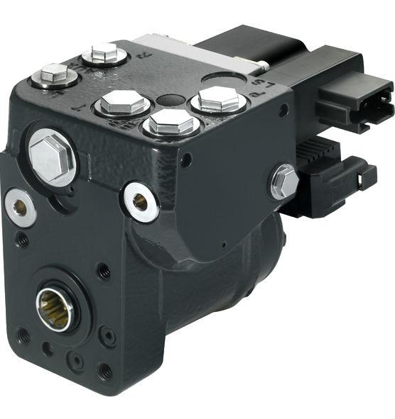
6 General General steering valve type OSPE On tractors, combine harvesters, maize harvesters and other simulate vehicles there is often a need for electrically actuated steering to make automatic GPS controlled steering possible. Also manual steering with variable ratio is an often wanted feature to improve productivity and driver comfort. For this purpose Danfoss has developed a combined steering unit and electro hydraulic steering valve named OSPE: OSP for normal manual steering wheel activated steering and E for electro hydraulic steering activated by electrical input signal either from GPS or vehicle controller or from steering wheel sensor (Danfoss type SASA) for variable steering ratio. In variable steering mode, the electro hydraulic valve part adds flow to the metered out flow from the steering unit part of the OSPE. OSPE has build in safety function in form of cut off valve, which makes unintended steering from Electro hydraulic valve part impossible. So OSPE is the right steering element first of all to build up steering system with very high safety level and so to be able to fulfill legislations demands like e.g. demands in EU Machinery Directive 2006/42/EC. OSPE is offered with the PVED-CLS steering valve controller. PVED-CLS offers integrated, flexible software-based electrohydraulic steering functionality which can be tailored to any off-road vehicle type by software parameterization. The PVED-CLS also works as a certified Safety Controller. For further details about PVED-CLS, see OSPE with PVED-CLS Steering Valve Controller Data Sheet, L In cases where space do not allow room enough for OSPE, an ordinary OSP non-reaction steering unit combined the EH-Electro Hydraulic In-Line steering valve is an alternative. EH valves are offered with the same safety functions as OSPE. Please contact Danfoss sales organisation. 6 Danfoss July BC en-US0502
7 Versions Overview Steering valve OSPE and electrical actuation module PVE Steering unit part Version Spool/sleeve type Gear set OSPEC xxx LSRM C -dynamic, LSRM, Load Sensing, Reaction Single OSPEF xxx LS F -dynamic, LS, Non-Reaction Single OSPEDC xx/yyy LSRM C -dynamic, LSRM, Load Sensing, Reaction Dual OSPEDF xx/yyy LS F -dynamic, LS, Non-Reaction Dual EH-part of OSPE in combination with any OSPE Spool type Static PVE actuator PVES, PVED CC, PVED CLS Priority valve in OSPE in combination with any OSPE Spool type Dynamic Note If priority valve is present elsewhere in system, OSPE can be w.o. priority valve. Danfoss July BC en-US0502 7
8 Versions OSPEC LSRM with PVED-CLS: This version is preferred for front wheel steered vehicles, like e.g. tractors, where self-alignment steering effect is desired. Reaction type steering resembles a car where the direction of travel will continue straight ahead when ever the steering wheel is not touched. The reaction concept in any OSPE steering units is based on Danfoss RM technology. The reaction effort is selectable by help of the solenoid valve for activating EH steering: Road mode: When EH steering is powered off, then OSPE behaves the same as a Reaction unit Field mode: When EH steering is powered on, then OSPE behaves the same as a Non-reaction unit OSP L R EH Rr Lr P T PVED-CLS LS Electronics PE TE LS P EF LS T L R P Danfoss July BC en-US0502
9 Versions OSPEF LS with PVED-CLS This version is preferred for rear wheel steered vehicles, like e.g. combines. In both modes: Road mode: When EH steering is un powered Field mode: When EH steering is powered the steering unit part behaves as a Non-reaction steering unit. The F -spool type is preferred for steering systems where high level of negative steering forces may be present e.g. articulated steered vehicles. OSP L R EH Rr Lr P T PVED-CLS LS Electronics PE TE LS P EF LS T L R P Danfoss July BC en-US0502 9
10 Versions OSPEDC LSRM with PVES This version is preferred for front wheel steered vehicles, like e.g. tractors, where self-alignment steering effect is desired. Only difference compared to OSPEC LSRM is that D type has 2 gear wheel sets (rotary meters). Should the pump supply be lost, only one gear set is active for emergency steering. In normal steering situations both gear sets are active. OSP L R Rr Lr P LS EH PVES Electronics PE TE LS P EF T L R P Danfoss July BC en-US0502
11 Versions OSPEDF LS with PVES This version is preferred for rear wheel steered and articulated vehicles. Only difference compared to OSPEF LS is that D type has 2 gear wheel sets (rotary meters). This version however is shown without priority valve. OSP L R P LS EH PVES Electronics PE TE LS P T L R P Danfoss July BC en-US
12 PVED-CL/CLS Only promote PVED-CLS for new applications. PVED-CL is only used in existing codes established until start of For details about PVED-CLS, see OSPE with PVED-CLS Steering Valve Controller Data Sheet, L OSPE with an electrical programmable module (PVED-CLS) the following steering features in electro hydraulic steer mode/field mode are possible: GPS-steering Row sensor/ camera steering Joy stick or mini st. wheel steering Variable steering ratio Speed depending steering ratio 12 Danfoss July BC en-US0502
13 Function OSPE steering valve , 10, 11 14, 15, P The OSPE steering valve includes the following main components Shock valves Suction valves Spool/sleeve set Gear set Mode select and EH cut off valve EH directional valve PVE control unit LVDT transducer Solenoid valve bridge Control valve for mode select Pilot reduction valve, 12 bar PP damping orifice Priority valve spool Priority valve spring Dynamic orifice Pilot pressure relief valve PVFC valve/ls resolver Neutral spring package for spool/sleeve Danfoss July BC en-US
14 Function OSPEC LSRM with PVED-CLS Neutral position 1 2 OSP L R EH Rr Lr P T 9 PVED-CLS Electronics LS PE TE LS P EF LS T L R P Shock valves 12 Control valve for mode select 2 Suction valves 13 Pilot reduction valve, 12 bar 3 Spool/sleeve set 14 PP damping orifice 4 Emergency steering check valve 15 Priority valve spool 5 Gear set 16 Priority valve spring 6 P-check valve 17 Dynamic orifice 7 Mode select and EH cut off valve 18 Pilot pressure relief valve 8 EH directional valve 19 LS orifice 9 PVE control unit 20 LS check valve 10 LVDT transducer with dual signal 21 PVFC valve/ls resolver 11 Solenoid valve bridge 22 Neutral spring package for spool/sleeve When the engine is turned off, the priority valve spool (15) is pushed to the left by the spring (16). 14 Danfoss July BC en-US0502
15 Function The passage to the EF port is blocked and the passage to CF to the OSP spool/sleeve set (3) and to the EH directional valve spool (8) is open. When the engine is on and the steering unit OSP and EH is in neutral position, the CF pressure will rise to match the spring force in the priority valve, and the priority valve spool (15) will move to the right and the oil will pass from the pump across the integrated priority valve spool (15) and out through the EF port. The priority valve is a dynamic type, meaning that a flow passes from CF through the Dynamic orifice (17) (integrated in spool 15) and into the LS line through the LS orifice (19), LS check valve (20), the PVFC valve (21) and into the spool/sleeve set (3). In neutral position this dynamic oil flow passes on to the tank. When the steering unit is in neutral position and control valve (12) is deactivated, then the mode select/eh cut off valve (7) makes connection through the Reaction circuit, Lr and Rr. So if the steering wheel is untouched and a delta P is generated in the steering cylinder, oil will pass from L to R or R to L through the spool/sleeve set (3) and gear set (5) and the steering wheel will rotate until it is grabbed or delta P disappears. Only the force of the neutral spring package (22) has to be overcome to stop the rotation of the steering wheel and therefore stop the cylinder movement. The mode select/eh cut off valve (7) makes unintended EH steering impossible, if e.g. a false input signal comes to the PVE control unit (9), when the control valve (12) is deactivated, because L and R connections from EH directional valve spool (8) are blocked in (7). If the control valve (12) is activated, then the mode select/eh cut off valve (7) blocks connection through the Reaction circuit. In this position there will be no reaction behavior even if there is build up delta P on the steering cylinder from forces on the steered wheels. So the steering unit behaves as a Non reaction OSP. In that situation (If the control valve (12) is activated) EH steering is possible. Danfoss July BC en-US
16 Function Steering right with steering wheel 1 2 OSP L R EH Rr Lr P T 9 PVED-CLS Electronics LS PE TE LS P EF LS T L R P Shock valves 12 Control valve for mode select 2 Suction valves 13 Pilot reduction valve, 12 bar 3 Spool/sleeve set 14 PP damping orifice 4 Emergency steering check valve 15 Priority valve spool 5 Gear set 16 Priority valve spring 6 P-check valve 17 Dynamic orifice 7 Mode select and EH cut off valve 18 Pilot pressure relief valve 8 EH directional valve 19 LS orifice 9 PVE control unit 20 LS check valve 10 LVDT transducer with dual signal 21 PVFC valve/ls resolver 11 Solenoid valve bridge 22 Neutral spring package for spool/sleeve When steering with the steering wheel to the right, the spool of the spool/sleeve set (3) will rotate relative to the sleeve. So LS line will be connected to R-side. LS pressure will raise accordingly to steering pressure required and priority valve spool (15) will be pressed to the left and oil will stream through the 16 Danfoss July BC en-US0502
17 Function internal CF side of the priority valve and on to the spool/sleeve set (3) through the gear set (5) and out through the R connection. In parallel the L side is opened through the spool/sleeve set (3) to tank (T). When steering up against cylinder end stop, pressure will raise in LS line according to setting of pilot pressure control valve (18). Check valve (20) avoids oil to stream backwards from servo side (R in this case) and over valve (18) to tank. So the valve (18) shall only open for the dynamic flow generated in the dynamic orifice (17) of priority valve part, independent if steering is done by the steering wheel (OSP part) or by the EH valve. Danfoss July BC en-US
18 Function Steering right with EH 1 2 OSP L R EH Rr Lr P T 9 PVED-CLS Electronics LS PE TE LS P EF LS T L R P Shock valves 12 Control valve for mode select 2 Suction valves 13 Pilot reduction valve, 12 bar 3 Spool/sleeve set 14 PP damping orifice 4 Emergency steering check valve 15 Priority valve spool 5 Gear set 16 Priority valve spring 6 P-check valve 17 Dynamic orifice 7 Mode select and EH cut off valve 18 Pilot pressure relief valve 8 EH directional valve 19 LS orifice 9 PVE control unit 20 LS check valve 10 LVDT transducer with dual signal 21 PVFC valve/ls resolver 11 Solenoid valve bridge 22 Neutral spring package for spool/sleeve Before it is possible to steer with the EH part of the OSPE, it is needed to power the control valve for mode select (12) for field mode. When this valve is powered, the pilot supply (12 bar) is lead from the pilot reduction valve (13) through the control valve (12) to the EH cut off valve (7). So the valve (7) makes 18 Danfoss July BC en-US0502
19 Function PVES and PVED-CLS, electrical actuation connection from EH directional valve (8) to the cylinder ports, L and R, and (7) also leads pilot supply to the solenoid valve bridge (11) of the PVED CLS control unit (9) In the same shift, the valve (7) interrupts the reaction circuit, Lr and Rr, from the spool/sleeve set (3) to the cylinder ports, and the unit acts as a non-reaction OSP in this mode. When an input signal is transmitted to the electrical connector of the PVE (9), in this example signal to steer to the right, the solenoid valve bridge (11) is activated and the EH directional valve spool (8) is moved to the right. So LS in the spool (8) will sense the needed steering pressure, and this is transmitted to the PVFC valve /LS resolver (21). So the valve (21) makes restrictions in the dynamic LS flow from dynamic orifice (17) of priority valve, and the LS pressure in the priority valve spool (15) will match the LS pressure required from the EH directional valve spool (8). Accordingly the position of the priority valve spool (15) will change to match the flow and pressure demand for EH-steering. In case the watch dog part of the PVED CLS registers an unintended steering movement e.g. due to a false input signal to the PVE, the electrical power to the control valve for mode select (12) will be switched off. So valve 12 will dump pilot pressure to tank, mode select and EH cut off valve (7) will change position so that connection from EH directional valve spool (8) to cylinder ports will be blocked. Furthermore it will not be possible to activate the solenoid valve bridge (11) and the PVE will go into/stay in neutral position. In this way a true safe state is established. The non-reaction circuit from the OSP part is always connected to L and R cylinder ports independent of position of mode select valve (7), and so OSP steering is always possible. The philosophy of Danfoss electro hydraulic actuation, type PVE, is integration of electronics, sensors and actuators into a single unit that interfaces directly to the OSPE steering valve body. Closed loop control All the proportional actuators feature an integrated feedback transducer that measures spool movement in relation to the input signal, and by means of a solenoid valve bridge, controls the direction, velocity and position of the directional spool of the valve. The integrated electronics compensate for flow forces on the spool, internal leakage, changes in oil viscosity, pilot pressure, etc. This results in lower hysteresis and better resolution. Furthermore the electronics enable built in safety like fault monitoring, directional indication and LED light indication. Principle In principle the input signal (set-point signal) determines the level of pilot pressure which moves the main spool. The position of the directional spool is sensed in the LVDT transducer which generates an Danfoss July BC en-US
20 Function electric feed-back signal registred by the electronics. The variation between the set-point signal and feedback signal actuates the solenoid valves. The solenoid valves are actuated so that hydraulic pilot pressure drives the directional spool into the correct position. Inductive transducer, LVDT (Linear Variable Differential Transformer). When the directional spool is moved, a voltage is induced proportional to the spool position. The use of LVDT gives contact-free monitoring of the directional spool position. This means an extra-long working life and no limitation as regards the type of hydraulic fluid used. In addition, LVDT gives precise position signal of high resolution. Integrated pulse width modulation Positioning of the directional spool in PVES is based on the pulse width modulation principle. As soon as the directional spool reaches the required position, modulation stops and the spool is locked in position. 20 Danfoss July BC en-US0502
21 Technical data OSPE The technical data for OSPE are typical measured results. For the hydraulic system a mineral based hydraulic oil with a viscosity of 21 mm 2 /s [102 SUS] and a temperature of 50 C [122 F] was used. Gear set Single, range cm 3 /rev [ in 3 /rev] Dual, range 60/ /440 cm 3 /rev [3.7/ /26.8 in 3 /rev] Max. pressure Port P, EF 250 bar [3625 psi] Port LS 210 bar [3045 psi] Port L, R 280 bar [4060 psi] Port T 25 bar [362 psi] Oil flow rated Port P, EF 90 l/min [23.8 US gal/min] Port L/R, steering wheel steering 50 l/min [12.2 US gal/min] Port L/R, EH steering 12, 20, 30, 40 or 50 l/min [3.2, 5.3, 7.9, 10.6 or 13.2 US gal/min] Spool travel, EH directional spool ± 4 mm [± 0.16 in] Dead band, EH-directional spool, nominal ± 0.8 mm [± 0.03 in] Priority valve Type Dynamic Oil temperature Spring force 7 bar, 10 bar optional [100 psi, 145 psi optional] Nominal flow 90 l/min [23.8 US gal/min] Recommended temperature 30 --> +60 C [86 --> +140 F] Min. temperature -30 C [-22 F] Max. temperature +90 C [190 F] Ambient temperature > +60 C [-22 --> +140 F] Oil viscosity Operating range mm 2 /sec [ SUS] Filtration Temperature difference between steering unit and other hydraulics Min. viscosity 10 mm 2 /sec [58.9 SUS] Max. viscosity 460 mm 2 /sec [2134 SUS] Max contamination (ISO 4406) 21/19/16 Max. 10 C [50 F] Weights Weight of OSPE Type Weight kg [lb] OSPE [28.0] OSPE [28.2] OSPE [28.4] OSPE [28.7] OSPE [28.9] OSPE [29.1] OSPE [29.8] OSPE [29.5] Danfoss July BC en-US
22 Technical data Weight of OSPE (continued) Type Weight kg [lb] OSPE [30.2] OSPE [31.1] OSPE [31.3] OSPE [32.0] Weight of OSPED Type Weight kg [lb] OSPED 60/ [32.2] OSPED 60/ [32.9] OSPED 60/ [33.5] OSPED 70/ [32.6] OSPED 70/ [34.2] OSPED 80/ [33.1] OSPED 80/ [34.8] OSPED 100/ [33.5] OSPED 100/ [34.0] OSPED 125/ [33.7] OSPED 125/ [35.3] PVES PVES Supply voltage U DC range 11 V to 32 V rated 11 V to 32 V max. ripple 5% Current consumption at rated voltage PVES V V Signal voltage neutral 0.5 x U DC Signal current at rated voltage Input impedance in relation to 0.5 U DC Input capacitor Power consumption PVES CR-port CL-port 0.25 U DC to 0.75 U DC 0.25 ma to 0.70 ma 12 KΩ 100 ηf 7 W Supply voltage Function PVES Prop. super s Disconnected by means of neutral switch Reaction time from neutral position to max. spool travel max rated min Danfoss July BC en-US0502
23 Technical data Supply voltage Function PVES Prop. super s Disconnected by means of neutral switch Constant voltage Constant voltage Reaction time from max. spool travel to neutral position Reaction time from neutral position to max. spool travel Reaction time from max. spool travel to neutral position max rated min max rated min max rated min PVED-CLS For details about PVED-CLS, see OSPE with PVED-CLS Steering Valve Controller Data Sheet, L Hysteresis, PVES and PVED-CLS Hysteresis, PVES and PVED-CLS 1) rated 0% 1) Hysteresis is indicated at rated voltage and f = 0.02 Hz for one cycle (one cycle = neutral -> full CL -> full CR -> neutral. Spool travel PVES Oil consumption Supply voltage Function PVES Without voltage Pilot oil flow neutral 0.3 l/min [0.078 US gal/min] With voltage Pilot oil flow locked 0.1 l/min [0.026 US gal/min] continuous actuations 0.8 l/min [0.211 US gal/min] Oil viscosity Oil viscosity range mm 2 /s [ SUS] min. 4 mm 2 /s [39 SUS] max. 460 mm 2 /s [2128 SUS] Note: Max. start up viscosity 2500 mm 2 /s Danfoss July BC en-US
24 Technical data Oil temperature Oil-temperature Rec. range C [ F] min. -30 C [-22 F] max. 90 C [194 F] Filtering Filtering in the hydraulic system Max. allowed degree of contamination (ISO 4406, 1999 version): 23/19/16 Ambient temperature Ambiant temperatur range Rec C [ F] Pilot pressure Pilot pressure (relative to T pressure) nom bar [196 psi] min. 10 bar [145 psi] max. 15 bar] [217 psi] Enclosure and connector version Version of connector AMP JPT connector Deutsch connector Grade of enclosure 1) IP 66 IP 67 1) According to the international standard IEC 529 In particulary exposed applications, protection in the form of screening is recommended. Coil of control valve for mode select Below technical data are valid for coil of control valve for mode select, when this coil is connected directly to the wiring of the application. For OSPE with PVED-CLS the coil will be connected to the PVED-CLS. For more information, see OSPE with PVED-CLS Steering Valve Controller Data Sheet, L Specifications Duty cycle rating: 100% Magnet wire insulation: Class H (180C) Ambient temperature: -30 to 60 C [-22 to 140 F] Diodes are available; contact your Danfoss representative. Environmental protection: IP65 Input voltage tolerance: ±10% All AC coils are internally rectified 24 Danfoss July BC en-US0502
25 Technical data Ambient Temperature (deg C ) Minimum pull-in voltage D08 16 watt coil Maximum operating limit 70% 80% 90% 100% 110% 120% 130% 140% Percent Rated Voltage P E Electrical specifications 16 watt coils Voltage (V) Resistance (Ohms) 20 C [72 F] Current draw (A) at 25 C [77 F] Color 12 V DC Gray Terminals Amp Junior Timer Code AJ 56.6 [2.23] P Part number Voltage (V) Power (W) Part number 12 V DC 16 D D-AJ DEUTSCH Code DE 45.2 [1.78] 60.7 [2.39] P Danfoss July BC en-US
26 Technical data Part number Voltage (V) Power (W) Part number 12 V DC 16 D D-DE 26 Danfoss July BC en-US0502
27 Dimensioning Dimensioning steering system with OSPE steering valve The cylinder flow is determined from steering cylinder volume, number of revolutions on steering wheel from lock to lock and steering speed. Dimension of steering cylinder(s) can be based on formulas in General, steering components page Symbols: V (l) i (rev) Vvc (cm 3 /rev.) CQ (l/min) Pems (bar) Tems (Nm) Fe (N) Swd (m) Vvs (cm 3 /rev) PQ (l/min) Qpm (l/min) steering cylinder volume number of steering wheel revolutions from lock to lock steering system displacement for steering cylinder nominal cylinder flow emergency steering pressure emergency steering torque emergency steering wheel rim force steering wheel diameter displacement, steering unit pilot flow pump flow, minimum Example: Cylinder volume: V = 1.85 l [0.49 US gal] Required number of steering wheel revolutions from lock to lock: i = 4 5 revolutions The required steering system displacement for steering cylinder is calculated from Vvc = V/i = (1.85*1000)/5 = 370 cm 3 /rev [22.58 in 3 /rev] (1.85*1000)/4 = 463 cm 3 /rev [28.25 in 3 /rev] In this example we chose Vvc = 400 cm 3 /rev [24.4 in 3 /rev] The nominal cylinder flow at 100 rpm speed on steering wheel. CQ = 400 * 100/1000 (cm 3 /l) = 40 l/min [10.57 US gal/min]in this case we try to use an D type steering unit to avoid emergency steering pump. The small gear set, which is the only hydraulically active gear set in emergency steering mode is determined by the demand for emergency steering pressure, look in General, steering components page Emergency steering pressure, Pems, is calculated to be maximum Pems = 40 bar [580 psi] Maximum allowable steering torque Tems based on steering wheel rim force Fe=350 N and steering wheel diameter Swd = m Tems = Fe * Swd/2 = 350 * 0.381/2 = 66.7 Nm [580 lbf in] Emergency steering unit displacement can be chosen/calculated from the table lowest on page 29 in General, steering components. The nearest displacement Vvs generating minimum 40 bar [580 psi]at Tws = 66.7 N m [580 lbf in] Vvs maximum = 80 cm 3 /rev [4.88 in 3 /rev] So the closest combination on gear sets for this OSPED type will be: 80/395. So the numbers of steering wheel revolutions from lock to lock will be. i = V/Vvc = 1850/395 = 4.7 turns lock to lock. Danfoss July BC en-US
28 Technical characteristics EH-directional spools of OSPE Cylinder flow characteristic for directional spools Q E l/min US gal/min E 50 D D 35 C C B B A A 5 L mm R Can Us/UDC P A = B = C = D = E = valid for spools for nominal cylinder flow CQ = 12 l/min [3.17 US gal/min] valid for spools for nominal cylinder flow CQ = 20 l/min [5.28 US gal/min] valid for spools for nominal cylinder flow CQ = 30 l/min [7.97 US gal/min] valid for spools for nominal cylinder flow CQ = 40 l/min [10.57 US gal/min] valid for spools for nominal cylinder flow CQ = 50 l/min [13.21 US gal/min] The curves are valid for OSPE with internal priority valve w. 7 bar [100 psi] spring and 1.0 mm [0.039 in] dynamic orifice 60 l/min [15.85 US gal/min] pump flow. For OSPE without internal priority valve, the curves are valid in combination with external priority valve OLS 80, 60 l/min [15.85 US gal/min] pump flow. Pilot pressure relief valve: (P - T, Qp) characteristic The pilot pressure relief valve protects the steering system against excessive pressure. The pilot pressure relief valve works together with the priority valve in the OSPE to limit the maximum steering pressure P-T. The pilot pressure relief valve is set at an oil flow to the priority valve of 25 l/min [6.6 US gal/min]. Setting tolerance: rated value +10 bar [145 psi]. 28 Danfoss July BC en-US0502
29 Technical characteristics P-T psi P-T bar bar [2900 psi] 170 bar [2465 psi] 140 bar [2030 psi] Qp l/min Qp US gal/min V Pressure drop P-EF for Danfoss OSPE valve This data comes from measurements on a representative sample of OSPE valves from production. Oil with viscosity of 21 mm 2 /s at 50 C was used during measuring. Measurement is made when the pressure on the LS connection is zero. The minimum curve applies when the pressure on the EF connection is higher than the actual control spring pressure. The curve for control spring pressure of 7 bar [100 psi] and 10 bar [145 psi] applies when pressure on the EF port is zero. OSPE with priority valve spool P-EF psi P-EF bar bar [145 psi] 7 bar [102 psi] min Qp l/min Qp US gal/min P Danfoss July BC en-US
30 Dimensions OSPE dimensions with PVED-CLS 127 [5.00] 111 [4.37] 71.5 [2.81] 55.5 [2.19] 36.5 [1.44] 18 [0.71] OSPE 157 [6.18] 111 [4.37] Ø44.4 ±0.05 [Ø1.75 ±0.002] 51 [2.01] Ø25.4 [Ø1.00] 4.5 [0.18] L2 L1 92 [3.62] 31 [1.22] 65 [2.56] 27 [1.06] 37 [1.46] 77 [3.03] 7 [0.28] 2.8 [0.11] min. 7.1 [0.29] 92 [3.62] 146 [5.75] 45 A Ø82±0.3 [Ø3.23 ±0.01] P Metric-port version (ISO ): P, T, EF: M22 x 1.5, 15 mm deep L, R: M18 x 1.5, 14.5 mm deep LS: M12 x 1.5, 11.5 mm deep A: 4x M10 x 1.5, 16 mm deep 30 Danfoss July BC en-US0502
31 Dimensions OSPE dimensions with PVED-CC/CL OSPE 44.4 ± L2 213 L min OSPED 45 A 82±0.3 L3 L1 L P Metric-port version (ISO ): P, T, EF: M22 x 1.5, 15 mm deep L, R: M18 x 1.5, 14.5 mm deep LS: M12 x 1.5, 11.5 mm deep A: 4x M10 x 1.5, 16 mm deep OSPE dimensions Type L 1 L 2 mm [in] mm [in] OSPE [5.51] 13.0 [0.51] OSPE [5.63] 16.2 [0.64] OSPE [5.75] 18.6 [0.73] OSPE [5.83] 20.8 [0.82] OSPE [5.94] 24.0 [0.95] OSPE [6.02] 26.0 [1.02] OSPE [6.38] 35.1 [1.38] OSPE [6.30] 32.5 [1.28] OSPE [6.61] 40.9 [1.61] OSPE [7.05] 52.0 [2.05] Danfoss July BC en-US
32 Dimensions OSPE dimensions (continued) Type L 1 L 2 mm [in] mm [in] OSPE [7.20] 55.9 [2.20] OSPE [7.56] 65.0 [2.56] OSPED dimensions Type L 1 L 2 L 3 mm [in] mm [in] mm [in] OSPED 60/ [7.60] 9.1 [0.36] 9.1 [0.36] OSPED 60/ [7.91] 9.1 [0.36] 16.2 [0.64] OSPED 60/ [8.07] 9.1 [0.36] 20.8 [2.39] OSPED 70/ [7.76] 9.1 [0.36] 13.0 [0.51] OSPED 70/ [8.50] 9.1 [0.36] 32.5 [1.28] OSPED 80/ [8.11] 10.4 [0.41] 20.8 [0.82] OSPED 80/ [8.90] 10.4 [0.41] 40.9 [1.61] OSPED 100/ [8.23] 13.0 [0.51] 20.8 [0.82] OSPED 100/ [8.43] 13.0 [0.51] 26.0 [1.02] OSPED 125/ [8.35] 16.2 [0.64] 20.8 [0.82] OSPED 125/ [9.13] 16.2 [0.64] 40.9 [1.61] 32 Danfoss July BC en-US0502
33 Hydraulic systems OSPEC LSRM with PVED-CLS in a system with fixed gear pump, GPS receiver, joystick and mini wheel Vehicle speed GPS Display/MMI OSP L R Joystick Mini wheel SASA EH Rr P Lr LS Electronics PE PVED CLS TE LS P EF T L R Prime mover Working Hydraulic OC P The pump, the OSPE priority valve part and the working hydraulics must be protected by a separate pressure relief valve. The PVED CLS monitors input from the GPS, MMI, joy stick, mini wheel, steering angle sensor (SASA) and signal from steering cylinder sensor. In case of unintended movement from the cylinder sensor, the PVED CLS will remove power to the control valve for mode select/pilot dump, and in this way electro hydraulic actuation of steering cylinder is made impossible. The system turns into true safe state. Danfoss July BC en-US
34 Hydraulic systems OSPEC LSRM with PVED-CLS in a system with variable pump, GPS receiver, joystick and mini wheel Vehicle speed GPS Display/MMI OSP L R Joystick Mini wheel SASA EH Rr P Lr LS PE PVED CLS TE LS P EF T L R AUX Prime mover Working Hydraulic CC P The pump must have a built in pilot pressure relief valve to protect the OSPE, the priority valve part, the working hydraulics and the AUX function. AUX can be a brake system, which must have limited oil consumption to ensure steering capability in any case. Alternative pressure protection must be present in working and in AUX-hydraulic. 34 Danfoss July BC en-US0502
35 System safety Emergency steering The steering unit part of the OSPE acts like any other OSP steering units in case of no pump supply. In such case the gear wheel set acts as a hand driven pump, and so muscular power will be converted from input torque and rotation on the steering wheel to hydraulic power in the form of pressure and flow out of the cylinder port to which side the steering is done. See Dimensioning steering system with OSPE steering valve on page 27 in this catalog and page 28 in General, steering components for calculating manual/emergency steering. Please see promotional brochure for further information. OSPE and system safety PVES Fault monitoring A fault monitoring system is provided in all PVES modules. The system is available as passive fault monitoring type, which provides a warning signal only. Passive fault monitoring systems are triggered by three main events: 1. Input signal monitoring The PVES input signal voltage is continuously monitored. The permissible range is between 15% and 85% of the supply voltage. Outside this range the section will switch into an active error state. 2. Transducer supervision If one of the wires to the LVDT sensor is broken or short-circuited, the section will switch into an active error state. 3. Supervision of the closed loop The actual position must always correspond to the demanded position (input signal). If the actual spool position is further than the demanded spool position (>12%, ), the system detects an error and will switch into an active error state. On the other hand, a situation where the actual position is closer to neutral than that demanded will not cause an error state. This situation is considered in control. When an active error state occurs, the fault monitoring logic will be triggered: Passive fault monitoring A delay of 250 ms before anything happens. The solenoid valve bridge will not be disabled but still control the main spool position. An alarm signal is sent out through the appropriate pin connection, no. 3. This state is not memorized. When the erroneous state disappears, the alarm signal will turn to passive again. However, the signal will always be active for a minimum of 100 ms when triggered. To prevent the electronics from going into an undefined state, a general supervision of the power supply and the internal clock frequency is made. This function applies to PVES and will not activate fault monitoring: 1. High supply voltage The solenoid valves are disabled when the supply voltage exceeds 36 V, and the main spool will return/stay in neutral. 2. Low supply voltage: The solenoid valves are disabled when the supply voltage falls below 8.5 V, and the main spool will return/stay in neutral. 3. Internal clock The solenoid valves are disabled when the internal clock frequency fails, and the main spool will return/stay in neutral. Danfoss July BC en-US
36 System safety Safety considerations On-road operation W Warning The PVES or PVED-CLS shall be de-energized while driving on-road. It is the OEMs responsibility to establish the necessary means to inform and de-energize the PVE from the cabin when driving on public roads. The Danfoss range of PVE actuators are single string designs with limited on board fault monitoring. Danfoss strongly recommends application of vehicle specific safety monitoring systems that will detect non-conforming steering and effectively disable electro-hydraulic actuators or issue appropriate warnings as the case may be. A minimum safety system should include a manual power switch to electrical power off electro-hydraulic actuators while driving on public roads. For details, see: Technical information, PVE Series 4 User Manual PVED-CLS controller for Electro-Hydraulics Steering or contact Danfoss Technical Support Team 36 Danfoss July BC en-US0502
37 Order specification Variants and order specification Specification table for Danfoss OSPE steering valve. Part Variants OSP Gear set, cm 3 /rev Single 100, 125, 140, 160, 185, 200, 230, 250, 315, 400, 430, 500 Dual, D -type 60/120, 60/185, 60/200, 60/220, 60/260, 60/290 70/140, 70/170, 70/195, 70/230, 70/270, 70/320, 70/385 80/160, 80/205, 80/240, 80/280, 80/ /200, 100/260, 100/300, 100/ /250, 125/325, 125/440 Spool/sleeve C -dynamic, LSRM, Load Sensing, Reaction F -dynamic, LS, Non-Reaction Actuation module Type PVES 2) PVED CC PVED CLS 3) Connection AMP (A) DEUTSCH (D) Coil for control valve/pilot dump Connection AMP (A) DEUTSCH (D) EH-directional spool Cylinder flow, l/min Priority valve With spool, nominal flow, l/min 90 Spring force, bar 7 10 With out spool Housing 1) Thread Metric Relief valve Bar Shock valves Bar ) Only available with DEUTSCH 6 pin connector 3) Only available with DEUTSCH 12 pin connector 1) Housing, threads: No EF port present. P-flow determined by steering demand only 1) Housing threads P, T & EF L & R LS Metric, ISO M 22 x 1.5 O * * + S ** M 18 x 1.5 O * + S ** ** M 12 x 1.5 O * + S ** * O-ring chamfer on port connection ** Spot face around port connection OSPEF w. displacement < 250 cc/rev. and integrated priority valve not to be used! By experience we know the combination OSPEF with displacement < 250 cc/rev. and integrated priority may cause oscillations in steering system. Therefore do not specify such combinations. We recommend using OSPEC when displacement is smaller than 250 cc and if integrated priority valve is needed. Specify your wish to the OSPE according to the destinations as in the example underneath the empty scheme: Danfoss July BC en-US
38 Order specification Your wish OSPE Example OSPE D C 60/185 LSRM 20 PVES-D D 90 7 M PB Gear set type 2) Spool/sleeve Displacement Spool/sleeve EH spool PVE Coil for ctrl. valve Priority valve 3) Prio. vlv. spring 4) Housing, thread Relief valve setting Shock valves setting Unit painted black 2) 3) and 4) No designation for OSPE with single gear set No designation for OSPE without priority valve Code numbers Code numbers for catalog versions with specifications: Code numbers Specifications according to above description format OSPE C 100 LSRM 12 PVES-D D M PB OSPE C 125 LSRM 12 PVES-D D M PB OSPE C 160 LSRM 12 PVES-D D M PB OSPE C 200 LSRM 20 PVES-D D M PB OSPE C 250 LSRM 20 PVES-D D M PB OSPE C 315 LSRM 30 PVES-D D M PB OSPE C 400 LSRM 40 PVES-D D M PB OSPE C 500 LSRM 40 PVES-D D M PB For weights, please see Weights on page Danfoss July BC en-US0502
39 Danfoss July BC en-US

40 Products we offer: Bent Axis Motors Closed Circuit Axial Piston Pumps and Motors Displays Electrohydraulic Power Steering Electrohydraulics Danfoss Power Solutions is a global manufacturer and supplier of high-quality hydraulic and electronic components. We specialize in providing state-of-the-art technology and solutions that excel in the harsh operating conditions of the mobile off-highway market. Building on our extensive applications expertise, we work closely with our customers to ensure exceptional performance for a broad range of off-highway vehicles. We help OEMs around the world speed up system development, reduce costs and bring vehicles to market faster. Danfoss Your Strongest Partner in Mobile Hydraulics. Hydraulic Power Steering Go to for further product information. Integrated Systems Wherever off-highway vehicles are at work, so is Danfoss. We offer expert worldwide support for our customers, ensuring the best possible solutions for outstanding performance. And with an extensive network of Global Service Partners, we also provide comprehensive global service for all of our components. Joysticks and Control Handles Microcontrollers and Software Open Circuit Axial Piston Pumps Orbital Motors Please contact the Danfoss Power Solution representative nearest you. PLUS+1 GUIDE Proportional Valves Sensors Steering Transit Mixer Drives Comatrol Schwarzmüller-Inverter Local address: Turolla Hydro-Gear Daikin-Sauer-Danfoss Danfoss Power Solutions (US) Company 2800 East 13th Street Ames, IA 50010, USA Phone: Danfoss Power Solutions GmbH & Co. OHG Krokamp 35 D Neumünster, Germany Phone: Danfoss Power Solutions ApS Nordborgvej 81 DK-6430 Nordborg, Denmark Phone: Danfoss Power Solutions Trading (Shanghai) Co., Ltd. Building #22, No Jin Hai Rd Jin Qiao, Pudong New District Shanghai, China Phone: Danfoss can accept no responsibility for possible errors in catalogues, brochures and other printed material. Danfoss reserves the right to alter its products without notice. This also applies to products already on order provided that such alterations can be made without changes being necessary in specifications already agreed. All trademarks in this material are property of the respective companies. Danfoss and the Danfoss logotype are trademarks of Danfoss A/S. All rights reserved. Danfoss July BC en-US0502
Technical Information. Steering Unit OSPU. powersolutions.danfoss.com
 Technical Information Steering Unit OSPU powersolutions.danfoss.com Revision history Table of revisions Date Changed Rev March 2016 Updated to Engineering Tomorrow design 0202 May 2014 Converted to Danfoss
EHPS Steering Valve PVE Actuation Module OSPCX CN Steering Unit
 MAKING MODERN LIVING POSSIBLE Technical Information EHPS Steering Valve PVE Actuation Module OSPCX CN Steering Unit powersolutions.danfoss.com Revision history Table of revisions Date Changed Rev May 2015
OSPB, OSPC, OSPF, OSPD, OSPQ, OSPL Load Sensing Steering Units. OLS Priority Valves. OSQ Flow Amplifiers. Technical Information
 OSPB, OSPC, OSPF, OSPD, OSPQ, OSPL Load Sensing Steering Units OLS Priority Valves OSQ Flow Amplifiers Technical Information A Wide Range of Steering Components Revision History Table of Revisions Date
Sensor Steering Angle Sensor Absolute (SASA)
") MAKING MODERN LIVING POSSIBLE Electrical Installation Sensor (SASA) powersolutions.danfoss.com Revision history Table of revisions Date Changed Rev September 2015 Minor layout revision BB April 2014 Converted
MAKING MODERN LIVING POSSIBLE Electrical Installation Sensor (SASA) powersolutions.danfoss.com Revision history Table of revisions Date Changed Rev September 2015 Minor layout revision BB April 2014 Converted
Steering Valve EHPS and EHPS with OLS 320
 Service Manual Steering Valve EHPS and EHPS with OLS 320 powersolutions.danfoss.com Revision history Table of revisions Date Changed Rev July 2016 Updated EHPS spare parts list 0102 June 2015 First version
Steering Priority Valve OLS 160
 MAKING MODERN LIVING POSSIBLE Service Manual Steering Priority Valve OLS 160 powersolutions.danfoss.com Revision History Table of Revisions Date Changed Rev Mar 2014 Converted to Danfoss layout - DITA
Steering EHi Steering Valve
 Technical Information Steering powersolutions.danfoss.com Revision history Table of revisions Date Changed Rev January 2018 Function, Technical Characteristics, Coding ; minor corrections and additions
H1 Pump Filter Bypass Sensor
 MAKING MODERN LIVING POSSIBLE Electrical Installation H1 Pump Filter Bypass Sensor powersolutions.danfoss.com Revision history Table of revisions Date Changed Rev September 2015 Minor layout revision BC
Series 51 Motor Electrohydraulic Two-Position Controls T1, T2
 MAKING MODERN LIVING POSSIBLE Electrical Installation Series 51 Motor Electrohydraulic Two-Position Controls T1, T2 powersolutions.danfoss.com Revision history Table of revisions Date Changed Rev August
H1B Motor Two-Position Control E1, E2
 MAKING MODERN LIVING POSSIBLE Electrical Installation H1B Motor Two-Position Control E1, E2 powersolutions.danfoss.com Revision history Table of revisions Date Changed Rev July 2015 Converted to Danfoss
Phased Out Products. Proportional Valve Group PVG 83. Tech Note MAKING MODERN LIVING POSSIBLE
 MAKING MODERN LIVING POSSIBLE Tech Note Proportional Valve Group PVG 83 Valve system PVG 83 is a hydraulic load sensing valve designed to give the customer just the valve he needs. From a simple load sensing
Proportional Valve Group PVG 128/256
 Service and Parts Manual Proportional Valve Group powersolutions.danfoss.com Revision history Table of revisions Date Changed Rev July 207 First edition 00 2 Danfoss July 207 AX00000346en-US00 Contents
Series 51-1 Motor Pressured Compensated Controls TA
 MAKING MODERN LIVING POSSIBLE Series 51-1 Motor Pressured Compensated Controls TA powersolutions.danfoss.com Revision history Table of revisions Date Changed Rev August 2015 Converted to Danfoss layout
Proportional Valve Group PVG 120
 MAKING MODERN LIVING POSSIBLE Specification Proportional Valve Group PVG 120 powersolutions.danfoss.com Revision history Table of revisions Date Changed Rev May 2014 Converted to Danfoss layout DITA CMS
Steering OSPB, OSPC, OSPD Open Center and OSPB Closed Center
 echnical Information Steering OSB, OSC, OSD Open Center and OSB Closed Center powersolutions.danfoss.com evision history able of revisions Date Changed ev April 2016 Updated to Engineering omorrow design
MAKING MODERN LIVING POSSIBLE. Technical Information. Orbital Motors TMVW. powersolutions.danfoss.com
 MAKING MODERN LIVING POSSIBLE Orbital Motors TMVW powersolutions.danfoss.com Revision history Table of revisions Date Changed Rev September 2015 New curve for permissible shaft load 0201 November 2014
OSPB, OSPC, OSPR, OSPD Open Center Steering units OSPB Closed Center Steering units TAD Torque amplifiers. Technical Information
 OSPB, OSPC, OSPR, OSPD Open Center Steering units OSPB Closed Center Steering units TAD Torque amplifiers Technical Information A wide range of steering components A WIDE RANGE OF STEERING COMPONENTS F300599
H1B Motor Electric Two-Position Control T1, T2
 MAKING MODERN LIVING POSSIBLE Electrical Installation H1B Motor Electric Two-Position Control T1, T2 powersolutions.danfoss.com Revision history Table of revisions Date Changed Rev June 2015 Converted
EHPS Steering Valve PVE Actuation Module OSPCX CN Steering Unit. Technical Information
 EHPS Steering Valve PVE Actuation Module OSPCX CN Steering Unit Technical Information A Wide Range of Steering Components Revision History Table of Revisions Date Page Changed Rev Mar 2009 35 Note added
Steering Unit Type OSPB and OSPC Type ON and CN
 MAKING MODERN LIVING POSSIBLE Service Manual Steering Unit Type OSPB and OSPC Type ON and CN powersolutions.danfoss.com Revision History Table of Revisions Date Changed Rev Mar 2014 Converted to Danfoss
EHPS Steering Valve PVE Actuation Module OSPCX CN Steering Unit. Technical Information
 EHPS Steering Valve PVE Actuation Module OSPCX CN Steering Unit Technical Information A Wide Range of Steering Components Revision History Table of Revisions Date Page Changed Rev Mar 2009 35 Note added
MAKING MODERN LIVING POSSIBLE. Service Manual. Steering OSPM. powersolutions.danfoss.com
 MAKING MODERN LIVING POSSIBLE Service Manual Steering OSPM powersolutions.danfoss.com Revision History Table of Revisions Date Changed Rev Mar 2014 Converted to Danfoss layout - DITA CMS BA Feb 1998 First
Quick Reference Parts Manual Variable Displacement Motor Series 20, series powersolutions.danfoss.com
 MAKING MODERN LIVING POSSIBLE Quick Reference Parts Manual Variable Displacement Motor Series 20, 20-27 series powersolutions.danfoss.com 2 Contents Service parts Exploded view drawing (20 thru 23 series)...4
Orbital Motors OMEW Standard and with Low Speed Option
 MAKING MODERN LIVING POSSIBLE Technical Information Orbital Motors OMEW Standard and with Low Speed Option powersolutions.danfoss.com Revision history Table of revisions Date Changed Rev October 2014 Changed
S1X Generic Speed Control System
 MAKING MODERN LIVING POSSIBLE System Description S1X Generic Speed Control System powersolutions.danfoss.com Revision history Table of revisions Date Changed Rev August 2015 Danfoss Layout 0600 September
Product Reliability Data (MTTF) for S90P
 for S90P") MAKING MODERN LIVING POSSIBLE Functional Safety Product Reliability Data (MTTF) for S90P042-250 powersolutions.danfoss.com Revision history Table of revisions Date Changed Rev May 2015 Added Mission time
MAKING MODERN LIVING POSSIBLE Functional Safety Product Reliability Data (MTTF) for S90P042-250 powersolutions.danfoss.com Revision history Table of revisions Date Changed Rev May 2015 Added Mission time
Distribuíção, revenda emanutenção. CatálogosOnline. (11) (11)
 (11)") Distribuíção, revenda emanutenção CatálogosOnline (11)4174-3300-(11)4765-6775 www.hmc.com.br MAKING MODERN LIVING POSSIBLE Technical Information Axial Piston Pumps Series 20 powersolutions.danfoss.com
Distribuíção, revenda emanutenção CatálogosOnline (11)4174-3300-(11)4765-6775 www.hmc.com.br MAKING MODERN LIVING POSSIBLE Technical Information Axial Piston Pumps Series 20 powersolutions.danfoss.com
Orbital Motors Seal Kits
 Technical Information Orbital Motors Seal Kits powersolutions.danfoss.com Revision history Table of revisions Date Changed Rev October 2017 Added OMP X and OMR X data to table and updated to Engineering
Sensors KS10201 Microsyn Level Sensor
 MAKING MODERN LIVING POSSIBLE Technical Information Sensors powersolutions.danfoss.com Revision history Table of revisions Date Changed Rev November 2015 Converted to Danfoss layout 0001 August 2010 Initial
Technical Information Orbital Motors DH and DS powersolutions.danfoss.com
 MAKING MODERN LIVING POSSIBLE Technical Information Orbital Motors DH and DS powersolutions.danfoss.com and DS F 301 245 A Wide Range of Orbital Motors Danfoss Power Solutions is a world leader within
Technical Information Axial Piston Motors Series 20 powersolutions.danfoss.com
 MKING MODERN LIVING POSSILE Technical Information xial Piston Motors Series 20 powersolutions.danfoss.com General Information Introduction Danfoss a world leader in hydraulic power systems has developed
Product Reliability Data (MTTF) for H1P
 for H1P") MAKING MODERN LIVING POSSIBLE Functional Safety Product Reliability Data (MTTF) for H1P069-250 powersolutions.danfoss.com Revision history Table of revisions Date Changed Rev May 2015 Added CCO information
MAKING MODERN LIVING POSSIBLE Functional Safety Product Reliability Data (MTTF) for H1P069-250 powersolutions.danfoss.com Revision history Table of revisions Date Changed Rev May 2015 Added CCO information
Orbital Motors DH and DS
 MAKING MODERN LIVING POSSIBLE Orbital Motors DH and DS powersolutions.danfoss.com Orbital Motors, DH and DS F 301 245 A Wide Range of Orbital Motors Danfoss Power Solutions is a world leader within production
Technical Information Series 45 G Frame powersolutions.danfoss.com
 MAKING MODERN LIVING POSSIBLE Technical Information Series 45 G Frame powersolutions.danfoss.com Contents Frame G Design... 4 Specifications... 5 Performance G74B... 6 Performance G9C... 7 Order code...
Sensors ACX104B Potentiometer Rotary Position Sensor
 MKING MODERN LIVING POSSILE Technical Information Sensors CX104 Potentiometer Rotary Position Sensor powersolutions.danfoss.com Revision history Table of revisions Date Changed Rev November 2015 Conversion
Closed Circuit Axial Piston Pump DDC20
 Parts Manual Closed Circuit Axial Piston Pump powersolutions.danfoss.com Revision history Table of revisions Date Changed Rev July 2017 Updated to Engineering Tomorrow design 0302 2 Danfoss July 2017 AX00000134en-US0302
MAKING MODERN LIVING POSSIBLE. Phased Out Products. Technical Information. Level Controller. powersolutions.danfoss.com
 MAKING MODERN LIVING POSSIBLE Technical Information ACW112A,D Level Controller powersolutions.danfoss.com 2 BLN-95-8952-11 95-8952-11 August 2004 PRODUCT OVERVIEW Description... 4 Features... 4 Ordering
Closed Circuit Axial Piston Pumps H1 115/130 cc
 MAKING MODERN LIVING POSSIBLE Conversion Manual Closed Circuit Axial Piston Pumps H1 115/130 cc powersolutions.danfoss.com Revision history Table of revisions Date Changed Rev December 2015 First edition
Faster. Count on availability when you need it most H1B Bent Axis Motors Rapid Delivery Center. time to market. powersolutions.danfoss.
 Count on availability when you need it most H1B Bent Axis Motors Rapid Delivery Center Faster time to market Danfoss RDCs ensure you have the product you want, when you want it powersolutions.danfoss.com
Light and safe steering. with steering components from Sauer-Danfoss
 Light and safe steering with steering components from Sauer-Danfoss There are many good reasons for choosing Sauer-Danfoss for vehicle steering The prime objective of Sauer-Danfoss is to be a good partner
Parts Manual Closed Circuit Axial Piston Pump DDC20 powersolutions.danfoss.com
 MAKING MODERN LIVING POSSIBLE Parts Manual Closed Circuit Axial Piston Pump DDC20 powersolutions.danfoss.com 2 Contents General Information Variable pump & fixed motor Service parts identification...4
Transit Mixer Drives System Series TM
 MAKING MODERN LIVING POSSIBLE System Description Transit Mixer Drives System Series TM powersolutions.danfoss.com Revision History Table of Revisions Date Changed Rev Mar 2014 Converted to Danfoss layout
Service Parts Manual M25 Axial Piston Motor Series 40 powersolutions.danfoss.com
 MAKING MODERN LIVING POSSIBLE Service Parts Manual M25 Axial Piston Motor Series 40 powersolutions.danfoss.com 2 Contents General Information Service parts identification... 4 Nameplate... 4 Date code...
Sauer-Danfoss Global Steering Production
 Steering Products Sauer-Danfoss Global Steering Production Denmark, Nordborg HQ Poland, Wroclaw India, Pune 2 Sauer-Danfoss Steering Components Steering units (flow up to 100 l/min., system-pressure up
Efficient performance precise operation. PVG proportional valves
 Efficient performance precise operation. PVG proportional valves Modular system design enables customization for your varying vehicle control needs powersolutions.danfoss.com Flexible, efficient, and global
DH Technical Information. Versions. Versions
 Versions Versions Mounting flange Shaft Port size European version US version Side port version End port version Flange port version Standard shaft seal High pressure shaft seal Drain connection Check
60+ countries served by our global manufacturing facilities ensures market proximity
 Power and control for all your work function needs Series 45 Open Circuit Axial Piston Pumps 60+ countries served by our global manufacturing facilities ensures market proximity powersolutions.danfoss.com
MCX106A Hall Effect Level Sensor. Technical Information
 MCX106A Hall Effect Level Sensor Technical Information Revisions Revision History Table of Revisions Date Page Changed Rev 21 Jan, 2011 Initial release AA 2011 Sauer-Danfoss. All rights reserved. 2 Sauer-Danfoss
Directional Control Valve Model Technical Information. Phased Out OUT BASE BKT CYL ROD
 BASE BKT CYL ROD OUT IN Directional Control Valve Model 1480 Technical Information History of Revisions Revisions Table of Revisions Date Page Changed Rev. May 2008 - first edition AA 2008 Sauer-Danfoss.
Orbital X Modular Program
 Service Manual Orbital X Modular Program www.danfoss.com Revision history Table of revisions Date Changed Rev May 2018 Updated document with new S-Spring tool and information 0201 Apr 2018 Removed S-Spring
Orbital Motors with Speed Sensor
 MAKING MODERN LIVING POSSIBLE Technical Information Orbital Motors with Speed Sensor powersolutions.danfoss.com Revision history Table of revisions Date Changed Rev June 2015 Code numbers deleted under
PVG 32 Proportional Valves. Technical Information
 PVG 32 Proportional Valves Technical Information Contents general Function Technical data General...4 Function...7 PVG 32 valve group...7 PVPC, plug for external pilot oil supply...9 PVMR, friction detent...
Series ASC Anti Spin Control Valve
 MAKING MODERN LIVING POSSIBLE Technical Information Series ASC Anti Spin Control Valve powersolutions.danfoss.com Revision history Table of revisions Date Changed Rev March 2014 Converted to Danfoss layout
Proportional Valve Group PVG 120
 MAKING MODERN LIVING POSSIBLE Service Manual Proportional Valve Group PVG 120 powersolutions.danfoss.com Revision history Table of revisions Date Changed Rev May 2014 Converted to Danfoss layout DITA CMS,
Parts Manual Series cc Axial Piston Motor powersolutions.danfoss.com
 MAKING MODERN LIVING POSSIBLE Parts Manual Series 90 130 cc Axial Piston Motor powersolutions.danfoss.com 2 Contents General information Service parts identification...4 Nameplate...4 Date code...5 Service
PVG 120 Proportional Valves. Technical Information
 PVG 120 Proportional Valves Technical Information Contents CONTENTS General...3 Function...5 Hydraulic systems...7 Technical data...9 Electrical actuation... 12 Modules and code numbers... 16 PVP, pump
PVG 120 Proportional Valves. Service Parts Manual
 PVG 120 Proportional Valves Service Parts Manual Contents and Data Survey CONTENTS AND DATA SURVEY Page Sectional drawing... 3 Identification...4 Installation PVG... 5 Spare parts... 22 Pos. 1: PVP, pump
OMH. Repair Instructions
 OMH Table of Contents Revision View Date Page Changed Revision Jun 2006 New AA Apr 200 6 Japan location AB Sep 200 6 New back cover AC Safety Precautions Always consider safety precautions before beginning
Orbital Motor EMD Speed Sensor
 MAKING MODERN LIVING POSSIBLE Technical Information Orbital Motor EMD Speed Sensor powersolutions.danfoss.com Revision History Table of Revisions Date Changed Rev Feb 2014 Converted to Danfoss layout -
Orbital Motors OMS, OMT and OMV Orbital Motors
 MAKING MODERN LIVING POSSIBLE Technical Information Orbital Motors OMS, OMT and OMV Orbital Motors powersolutions.danfoss.com Revision history Table of revisions Date Changed Rev November 2014 Converted
OMT Series 2. Orbital Motors. Service Manual
 OMT Series 2 Orbital Motors Table of Contens, Special Versions Revision History Table of Revisions Date Page Changed Rev Sept 2003 CA Feb 200 4-5 Drain plug updated, Layout adjusted CB Sep 200 6 New back
Proportional Valve Group PVG 120
 Technical Information Proportional Valve Group PVG 120 powersolutions.danfoss.com Revision history Table of revisions Date Changed Rev March 2017 minor updates 1002 Mar 2014 Chapters re-order, Modules
OMR, OMR C, and OMRW N Series 5 and 6. Repair Instructions
 , C, and W N Series and Orbital Motors, C and W N Series and Table of Contents Revision View Safety Precautions Date Page Changed Revision 29 Jun, 200 all Changed from Danfoss to Sauer Danfoss lay out
T1P Transit Mixer Axial Piston Pump Size 069/089
 Technical Information T1P Transit Mixer Axial Piston Pump Size 069/089 powersolutions.danfoss.com Revision history Table of revisions Date Changed Rev May 2016 Updated to Engineering Tomorrow design. 0201
Series 51 - HZ, HA, HB, HE, HS, H1, H2, K1, K2, HP, HC, J1, J2, J3, J4, JA Hydraulic Proportional Controls
 MAKING MODERN LIVING POSSIBLE Service Manual Series 51 - HZ, HA, HB, HE, HS, H1, H2, K1, K2, HP, HC, J1, J2, J3, J4, JA Hydraulic Proportional Controls powersolutions.danfoss.com Revision history Table
OMP, OMP C, OMPW, and OMPW N Series 7 and 8. Repair Instructions
 , C, W, and W N Series and 8 Orbital Motors, C, and W/N Series and 8 Table of Contents Revision View Safety Precautions Date Page Changed Revision 29 Jun, 200 all Changed from Danfoss to Sauer Danfoss
OML and OMM Orbital Motors. Repair Instructions
 OML and OMM Orbital Motors Table of Contents, Revision View and Safety Precautions Revision View Date Page Changed Revision Jan 2008 all Changed from Danfoss to Sauer Danfoss lay out AA Mar 2008 13 Service
Service Manual Steering unit OSPQ and OSPD powersolutions.danfoss.com
 MAKING MODERN LIVING POSSIBLE Service Manual Steering unit OSPQ and OSPD powersolutions.danfoss.com Table of contents Exploded view OSPQ... 3 Tools... 4 Dismantling OSPQ... 5 Assembling OSPQ... 7 Exploded
Series 20 Axial Piston Pumps. Technical Information
 Series 20 Axial Piston Pumps Technical Information General Description INTRODUCTION Sauer-Danfoss a world leader in hydraulic power systems has developed a family of axial piston pumps. DESCRIPTION Sauer-Danfoss
OMEW Standard and with Low Speed Option. Orbital Motors. Technical Information
 Standard and with Low Speed Option Orbital Motors Technical Information Contents Revision History Table of Revisions Date Page Changed Rev Jan 2009 Many major change BA Mar 2010 16 Japan location BB Contents
MCX104A DC Microsyn Level Sensor. Technical Information
 MCX104A DC Microsyn Level Sensor Technical Information Revisions Revision History Table of Revisions Date Page Changed Rev 06 Apr 2011 4 Ordering Information BA 07 Dec 2010 Cover Added PLUS+1 Compliant
Series 20 Axial Piston Pumps. Technical Information
 Series 20 Axial Piston Pumps Technical Information General Description INTRODUCTION Sauer-Danfoss a world leader in hydraulic power systems has developed a family of axial piston pumps. DESCRIPTION Sauer-Danfoss
Hydraulic and Electronic Control Solutions Concrete Pump Truck
 Hydraulic and Electronic Control Solutions Concrete Pump Truck Best Partner for a future of intelligence Quality products and systems indicate lower maintenance cost and longer service life. Our global
PVG 120 Proportional Valves. Technical Information
 PVG 120 Proportional Valves Technical Information Contents Revision History Contents Function Hydraulic Systems Technical Data Electrical Actuation Modul and Code Numbers Technical Characteristics Dimensions
Directional Control Valve
 Directional Control Valve Service and Parts Manual powersolutions.danfoss.com Directional Control Valves Service and Parts Manual: Contents SERVICE PARTS Inlet cover... 3-4 Outlet cover... 5-6 Standard
Parts Manual Axial Piston Motors Series 40 MMF044D and MMV044D powersolutions.danfoss.com
 MAKING MODERN LIVING POSSIBLE Parts Manual Axial Piston Motors Series 40 MMF044D and MMV044D powersolutions.danfoss.com Front cover illustrations: P100 606 2 520L0586 Rev BB Nov 2013 Contents General Information
Hydrostatic Steering Unit Type OSPB, OSPC and OSPF. Service Manual
 Hydrostatic Steering Unit Type OSPB, OSPC and OSPF Table of Contens Revision History Table of Revisions Date Page Changed Rev Dec 2008 26 Tightening torque changed BC Table of contens... 2 Exploded view
Series TMM Axial Piston Motor. Technical Information
 Series TMM Axial Piston Motor Technical Information General Description GENERAL DESCRIPTION These motors are designed primarily to be combined with other products in closed circuit systems to transfer
Orbital Motors Type OMP, OMR and OMH. Technical Information
 Orbital Motors Type OMP, OMR and OMH Technical Information OMP, OMR and OMH A Wide Range of Hydraulics Motors F 301 245 A Wide Range of Hydraulic Motors Sauer-Danfoss is a world leader within production
PVG 100 Proportional Valve. Technical Information
 PVG 100 Proportional Valve Technical Information Contents GENERAL FUNCTION PVG 100 TECHNICAL DATA MODULES AND CODE NUMBERS General... 4 Valve system... 4 General features PVG 100... 4 PVP - Pump side module...
PVG 32 Proportional Valves. Technical Information
 PVG 32 Proportional Valves Technical Information Contents CONTENTS Page General...3 Function...5 PVG 32 valve group...5 PVPC, plug for external pilot oil supply...7 PVMR, friction detent...9 PVMF, mechanical
Electrohydraulic Actuators PVE Series 7
 Service Manual Electrohydraulic Actuators powersolutions.danfoss.com Revision history Table of revisions Date Changed Rev August 017 First edition 0101 Danfoss August 017 AX00000348en-US 0101 Contents
OML and OMM Orbital motors. Technical Information
 OML and OMM Orbital motors Technical Information OML and OMM A wide range of orbital motors F300030.TIF A WIDE RANGE OF ORBITAL MOTORS Sauer-Danfoss is a world leader within production of low speed orbital
PVG 120 Proportional Valves. Technical Information
 PVG 120 Proportional Valves Technical Information Revision History, Contents Table of Revisions Date Page Changed Rev Apr 2010 Various Layout, drawings and others HA Sep 2010 29, 44 Drawing, new back cover
Transit Mixer Axial Piston Motor Size 070/084/089
 Technical Information Transit Mixer Axial Piston Motor Size 070/084/089 powersolutions.danfoss.com Revision history Table of revisions Date Changed Rev June 2017 Update to Engineering Tomorrow 0202 Mar
Series 20 Axial Piston Motors. Technical Information
 Series 20 xial Piston Motors Technical Information General Description INTRODUCTION Sauer-Danfoss a world leader in hydraulic power systems has developed a family of axial piston motors. DESCRIPTION Sauer-Danfoss
ATEX instruction for OMR Special conditions for safe use
 User Manual ATEX instruction for OMR Special conditions for safe use powersolutions.danfoss.com Revision history Table of revisions Date Changed Rev September 2016 Minor updates 0103 March 2016 Minor updates
Series 40 MMF035D and MMV035D Axial Piston Motors
 Series 40 MMF035D and MMV035D Axial Piston Motors powersolutions.danfoss.com Revision history Table of revisions Date Changed Rev March 2018 Added shaft option B 0303 March 2018 Corrected cover image 0302
OMR Technical Information Versions
 Versions Versions Mounting flange Spigot diam,eter (front /rear end) Bolt circle diameter (BC) Shaft Port size European version US version Side port version End port version Flange port version Standard
PVG 120 Proportional Valves. Specifications
 PVG 120 Proportional Valves s Ordering guidance and remote control units ORDERING GUIDANCE The module selection chart and the order form are both divided into fields. Each module has its own field: 0:
Phased Out Products. Hydraulic motor with Drum Brake, OMSB. Spare parts MAKING MODERN LIVING POSSIBLE
 MAKING MODERN LIVING POSSIBLE Spare parts Hydraulic motor with Drum Brake, OMSB Cost-free repairs We would point out that cost-free repairs as mentioned in Danfoss General Conditions of Sale, are carried
Loop Flushing Valve. Lenntech. Technical Information. Tel Fax
 MAKING MODERN LIVING POSSIBLE Lenntech info@lenntech.com Tel. +31-152-610-900 www.lenntech.com Fax. +31-152-616-289 Revision history Table of revisions Date Change Rev Dec 2014 Danfoss Layout EA Oct 2011
Cartridge Mount Reverse Displacement Motors (RDM)
") Service Manual Cartridge Mount Reverse Displacement Motors (RDM) powersolutions.danfoss.com Revision history Table of revisions Date Changed Rev May 2016 new housing 0104 February 2015 update Port locations
Service Manual Cartridge Mount Reverse Displacement Motors (RDM) powersolutions.danfoss.com Revision history Table of revisions Date Changed Rev May 2016 new housing 0104 February 2015 update Port locations
Series 20 Axial Piston Motors. Technical Information
 Series 20 xial Piston Motors Technical Information General Description INTRODUCTION Sauer-Danfoss a world leader in hydraulic power systems has developed a family of axial piston motors. DESCRIPTION Sauer-Danfoss
Proportional Valve Group PVG 16
 MAKING MODERN LIVING POSSIBLE Technical Information Proportional Valve Group PVG 16 powersolutions.danfoss.com Revision History Table of Revisions Date Changed Rev Jan 2014 Converted to Danfoss layout
Servo solenoid valves with on-board electronics (OBE)
") Servo solenoid valves with on-board electronics (OBE) RE 29045/10.05 Replaces: 01.05 1/12 Type 5WRPE 10 Size 10 Unit series 2X Maximum working pressure P 1, P 2, A, B 210 bar, T 50 bar Nominal flow rate
Servo solenoid valves with on-board electronics (OBE) RE 29045/10.05 Replaces: 01.05 1/12 Type 5WRPE 10 Size 10 Unit series 2X Maximum working pressure P 1, P 2, A, B 210 bar, T 50 bar Nominal flow rate
Closed Circuit Axial Piston K and L Frame Variable Motors, SAE Mount
 MAKING MODERN LIVING POSSIBLE Service Manual Closed Circuit Axial Piston K and L Frame Variable Motors, SAE Mount powersolutions.danfoss.com Revision history Table of revisions Date Changed Rev November
MCH Customizing the Basic Control Handle
 Installation Guide MCH powersolutions.danfoss.com Revision history Table of revisions Date Changed Rev July 2017 Removed part numbers of obsolete product 0102 August 2016 Replaces BLN 95-9051 0101 2 Danfoss