MCH Customizing the Basic Control Handle
|
|
|
- Marsha McDowell
- 6 years ago
- Views:
Transcription

1 Installation Guide MCH powersolutions.danfoss.com
2 Revision history Table of revisions Date Changed Rev July 2017 Removed part numbers of obsolete product 0102 August 2016 Replaces BLN Danfoss July 2017 AN en-US0102
3 Contents MCHXXX Control Handle Ordering information Installation Adding and replacing parts Customer support Introduction...4 Theory of operation...4 Custom options...6 Technical data...6 Models... 9 Product identification chart...9 Nameplate part numbers list Assembly parts list...10 Accessories Dimensions...12 Panel cutout and mounting plate Surface mount Panel mount Assembly...15 Option 1: Assemble non-locking control knob...15 Option 2: Assemble center lock control knob...15 Mounting Option 1: Surface mount...15 Option 2 and 3: Top mount with case...15 Option 4 and 5: Panel mount with case Wiring Wiring diagram...16 Connection diagram Cam assembly drawing...18 Switches drawing...18 Single potentiometer drawing...18 Warnings Install new center switch...19 Install new auxiliary switch...19 Replace existing switches Replace spur gear...20 Replace potentiometer...20 Replace centering spring Replacing breaks Contact information...22 Danfoss July 2017 AN en-US0102 3
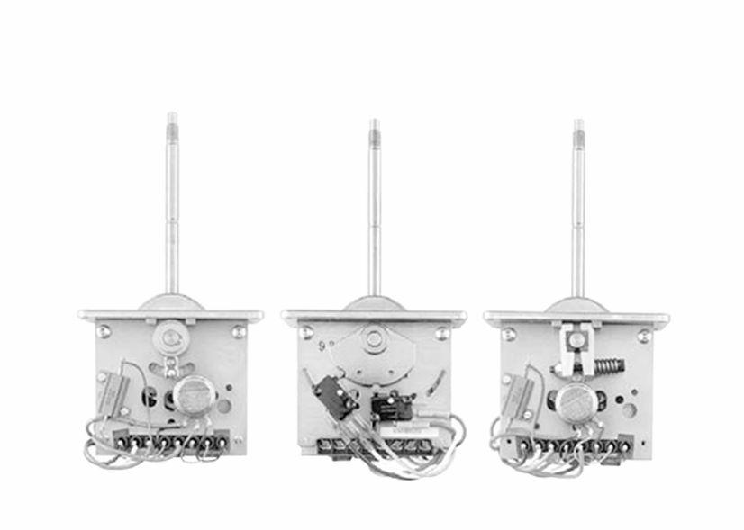
. These control handles are shipped without a knob or case.")
4 MCHXXX Control Handle Introduction From left to right: MCH00AD1252; Common back view; MCH00BD1252 The MCHXXX Control Handle is intended for use in open loop systems controlling Danfoss hydrostatic pumps with an Electrical Displacement Control (EDC). These control handles are shipped without a knob or case. This allows the Danfoss distributor to stock one model which can be completed to satisfy customer requirement. The basic control handles are factory wired and calibrated. Two models have been set up, one spring and one friction held, that can be used on 12 or 24 volt systems. The Control Handle is designed to provide man-machine interface. In addition to proportional operation of electrically controlled hydrostatics, switches may be incorporated to operate backup alarm, brake, and neutral interlock circuits. Theory of operation Single potentiometer control handles are generally used with a fixed output power supply. The power supply may be either an automotive-type battery for mobile equipment or an AC to DC convertor for industrial applications. Single potentiometer control handles are designed for both 12 and 24 volt power supply by terminal selection. Single potentiometer control handles have two advantages: Simplified electrical circuit Lower cost The only disadvantage is the limited output power that makes it unsuitable for applications with the MCE101 or driving more than one EDC simultaneously. A single coil or one coil of a dual coil EDC is connected as shown in the Connection diagram on page 17 and. The coil terminal connected to the common point of R2 and R3 (terminal 3) will all remain at or near half the supply (with R1 = 0 ohm) voltage as measured with respect to ground. The other side of the valve coil is connected to the potentiometer wiper (terminal 2). With the handle centered and the center switch actuated, it will also be at or near half the supply voltage. With the control handle centered, the voltage on each EDC terminal is the same and there is no current flow through the valve coil. Since it is current flow which causes the pump output flow to change, the pump will be at zero stroke. When the control handle is moved forward (as indicated by the forward arrow in the Wiring diagram on page 16), the voltage at \terminal 2 increases proportionally with distance traveled. At full handle stroke, the voltage at terminal 2 will be approximately 8.6 volts with respect to ground. The terminal 3 remains at half supply; thus a 2.6 volt differential will result (for 12 volt system and single coil valves). This differential voltage is sufficient to fully stroke any Danfoss pump. When the Control Handle is moved in the reverse direction, the voltage at the terminal 2 decreases to approximately 3.4 volts, the terminal 3 becomes more positive so current flows through the coil in the opposite direction resulting in flow out the other pump port. Although useful for understanding how the single potentiometer Control Handle functions, it is not normally necessary to measure the voltages with respect to ground. The voltage measured across the 2 and 3 terminals is more useful, since this is the actual differential voltage applied to the valve coil. The difference between 12 and 24 volt version is a resistor (R1) installed to limit the current through the bridge circuit. The value for R1 for 24 Vdc operation is 40 ohm, 25 W. A center-off switch is recommended 4 Danfoss July 2017 AN en-US0102
5 MCHXXX Control Handle for all single potentiometer type Control Handles. If one of the wires between the Control Handle and the pump control becomes shorted to ground (through worn insulation or broken wire), there would be sufficient electrical signal to fully stroke the pump. The center-off switch cuts the electrical power to the bridge circuit when the handle is in mechanical center of travel. Danfoss July 2017 AN en-US0102 5
6 MCHXXX Control Handle Custom options Choice of mounting styles with or without water tight case Mechanical options include center lock, spring return, friction held, and center detents 12 or 24 volt operation Environmentally hardened components designed for off-road construction equipment Optional cam operated switches Mounting 0 No case 1 Base or surface mount Connection is through four screws to the flanges on the bottom of the metal case. 2 Top mount with case The case is made of black nylon plastic. 3 Top mount without case Connection is through two screws to an enlarged mounting plate. Top mounting allows the entire handle to be removed from above the panel. 4 Panel mount with case The case is made of black nylon plastic. 5 Panel mount without case Connection is via four screws to the top plate that holds the boot in place. Type of control knob 0 No knob, non-locking 1 Non-locking The non-locking handle has a standard ball knob. The friction-held handle detents with a spring-loaded ball to indicate null, while the spring-return handle has a springpreload indicating null. 2 Center-lock The center-lock handle has a cylindrical knob and provides a positive center-lock that unlatches when the operator pulls up on the knob. Handle actuation A Spring-return, bidirectional This handle uses a torsion spring to return to the mechanical center position and has 30 of handle throw on either side of center. B Friction held, bidirectional This handle will maintain handle angle. Friction drag is adjustable. Connector 1 Terminal strip, internal Electrical connectors are made to a set of eight internal screw terminals. Technical data Operating voltage range 11 to 15 Vdc 12 volt models Wired to terminal 4 22 to 30 Vdc 24 volt models Wired to terminal 5 6 Danfoss July 2017 AN en-US0102
7 MCHXXX Control Handle Load resistance 15 to 30 ohm When used with Danfoss single and dual-coil EDC Auxiliary switch current capability (cam-actuated v3l microswitch) 3 amp Inductive at 28 Vdc Mechanical Handle stroke total travel ±30, 60 Spring torque at center breakaway 11 ± 4 inlb (1.2 ± 0.4 Nm) at full stroke 18 ± 6 inlb (2.0 ± 0.7 Nm) Detent torque over & above friction drag 10 inlb (1.1 Nm) Friction drag Friction is adjusted at brake assembly with dts" English Allen wrench and #k" open-ended wrench 13.5 ± 3 inlb (1.5 ± 0.3 Nm) Enviromental Temperature Operating -40 F to 170 F (-40 C to 77 C) Storage -30 F to 150 F (-34 C to 66 C) Humidity After being placed in a controlled atmosphere of 95% humidity at 100 F (38 C) for 10 days, the Control Handle will perform within specification limits. Rain Vibration NEMA 4 for units with aluminum case only. After being showered from all directions by a high-pressure hosedown, the Control Handle will perform within specification limits. Withstands a vibration test designed for mobile equipment control consisting of two parts: Cycling from 5 to 2000 Hz in each of the 3 axes. Resonance dwell for one million cycles for each resonance point in each of the 3 axes. Shock 50 g s for 11 ms Three shocks in both directions of the 3 mutually perpendicular axes for a total of 18 shocks. Life > 1,000,000 cycles Performance Null current ±5 ma maximum 12 Vdc operation Control Handle is centered and ±8 ma maximum 24 Vdc operation center-off switch is closed. Center dead zone ±3 nominal Handle travel required to actuate center-off switch. Full stroke output current 120 ma into 22 ohm load Factory test current Other full stroke currents optional. Danfoss July 2017 AN en-US0102 7
8 MCHXXX Control Handle Performance curve Output current Handle stroke 8 Danfoss July 2017 AN en-US0102
9 Ordering information Models Models MCH00AD1252 MCH00BD1252 Spring return model with two switches, one center off, one neutral start. Single potentiometer circuit for controlling Danfoss EDC from 12 or 24 volt supply Friction held model with two switches, one center off, one neutral start. Single potentiomter circuit for controlling Danfoss EDC from 12 or 24 volt supply. Product identification chart Name X X X X X XXX MCH Mounting Type of control knob Handle actuation Electrical characteristics Connector Factory assigned Mounting 0 No knob, no case 1 Base (surface) mount aluminum case 2 Top mount (drop-in) with plastic case 3 Top mount (drop-in) without plastic case 4 Panel mount with plastic case 5 Panel mount without plastic case Type of control knob 0 No knob, non-locking 1 Non-locking 2 Center lock Handle actuation A B Spring-return, bidirectional Friction held, bidirectional Electrical characteristics D Proportional, center-off and neutral start switch Connector 1 Terminal strip internal Danfoss July 2017 AN en-US0102 9
10 Ordering information Nameplate part numbers list Nameplate part numbers K16375 K16376 K16377 K16378 K16379 K16380 K16381 K16382 K16383 K16384 Spring actuation control handle type MCH11AD1252 MCH21AD1252 MCH31AD1252 MCH41AD1252 MCH51AD1252 MCH12AD1252 MCH22AD1252 MCH32AD1252 MCH42AD1252 MCH52AD1252 Nameplate part numbers K16385 K16386 K16387 K16388 K16389 K16390 K16391 K16392 K16393 K16394 Friction held control handle type MCH11BD1252 MCH21BD1252 MCH31BD1252 MCH41BD1252 MCH51BD1252 MCH12BD1252 MCH22BD1252 MCH32BD1252 MCH42BD1252 MCH52BD1252 Assembly parts list Assembly parts item numbers ? Danfoss July 2017 AN en-US0102
11 Ordering information Parts required to complete knob and case assemblies Item number Part number Quantity Name Type 1 K Knob X Boot X Nonlocking 3 K Knob top X 4 K Spring X 5 K Handle centerlock 6 K00024 As required Loctite 277 X Boot X Center lock X Surface Top/ case Top/no case Panel/ case 8 K Screw M5-13 X X X X X X 9 K Case fastner X X 10 K Gasket case seal X X 11 K Case plastic X X 12 K Leadwire strain relief 13 K Top mount plate X X 14 K Gasket top mounting 15 K Collar boot retainer 16 K Screw M5x16 X K Screw M5x16 for aluminum case 17 K Gasket X 18 K Aluminum case assembly 19 K Seal collar X X X X X X X 20 MCH00A 1 Handle spring X X X X Panel/ no case 21 MCH00B 1 Handle friction X 22 K Cam * 23 K Set screw * 24 K Wiring diagram Friction * These parts are required to change from one N/S switch and one center off switch to one center off switch and one forward or reverse switch. Spring Accessories EDC mating connectors K03383 K03384 K08106 Single-coil Packard Weather Pack 2-wire Dual-coil Packard Weather Pack 4-wire MS connector Danfoss July 2017 AN en-US
12 Installation Dimensions Panel cutout and mounting plate 138 (5.43) 7 (0.28) 50,8 (2.0) 25,4 (1.0) 85,5 MAX (3.37) 33,3 (1.31) 66,6 (2.62) 50,8 (2.0) 25,4 (1.0) 54,0 (2.12) 6,2 (4 HOLES) (0.25) 124 (4.88) 150,5 MAX (5.93) 1 4,5 ± (2) 2 12 Danfoss July 2017 AN en-US0102
13 Installation 1. Mounting plate 2. Remove burrs from both sides of panel to avoid damaging boot Surface mount 6,35 (0.25) 149,1 MAX (5.87) 136,4 ±0,4 (5.37) 63,76 MAX (2.51) 50,8 ±0,4 (2.0) 31,75 (1.25) 6,35 (0.25) 7,1 (4) (0.28) 30 REF 30 REF 30 REF 30 REF 302 MAX (11.88) 269,2 MAX (10.6) 96 MAX (3.78) MAX (4.72) 120 MAX (4.72) (1.06) 121 MAX (4.76) 14,2 (0.56) 121 MAX (4.76) 29,5 MAX (1.16) Danfoss July 2017 AN en-US
14 Installation 1. Customer panel Panel mount Left to right: Panel mount (drop in); Panel mount; Panel mount side view 30 REF 30 REF 30 REF 30 REF max. [9.9] MAX (5.9) MAX (4.45) 97.6 MAX (3.84) MAX (4.51) 60.4 (2.38) MAX (4.78) 29.5 (1.16) 60.4 (2.8) MAX (4.78) 29.5 (1.16) 44.4 (1.75) 64.1 MAX (2.52) 1. Customer panel 2. Tapping screws (2) 3. Remove collar that retains boot and discard 14 Danfoss July 2017 AN en-US0102
15 Installation Assembly Option 1: Assemble non-locking control knob Reference items in Assembly parts list on page Assemble boot (K22078 Item 2) over handle shaft so that ring inside of boot is in radius on handle shaft. Mold seams of boot should be 90 to handle axis. 2. Apply bead of Loctite (K00024 Item 6) three quarters of the length of internal threads in knob (K00566 Item1). 3. Screw knob onto handle shaft and hand tighten. Option 2: Assemble center lock control knob Reference items in Assembly parts list on page Assemble boot (K00635 Item 7) over handle center lock (K03454 Item 5) so that ring inside of boot is in radius of handle center lock and assemble over handle shaft. 2. Assemble spring (K00616 Item 4) to handle center lock. 3. Apply bead of Loctite (K00024 Item 6) three quarters of the length of internal threads in knob (K00617 Item3). 4. Screw knob onto handle shaft aligning center lock (K03545 Item 5) with D in knob and hand tighten. 5. Rotate boot so that mold seams of boot are 90 to handle axis. Check center lock for operation. Mounting Option 1: Surface mount Reference items in Assembly parts list on page Assemble gasket (K00558 Item 18) to handle (MCH00B Item 21 or K03734 Item 22). 2. Assemble handle to case (K02992 Item 19) so that notch on handle die cast cover is on same side as cable strain relief of case. 3. Assemble 4 seal collars (K00578 Item 9) to screw (K27329 Item 17) closed end of collars toward screw heads. 4. Assemble 4 screws to case and tighten to 25 ± 3 inlb. 5. Assemble boot retainer collar (K00562 Item 16) to boot. 6. Assemble 4 seal collars (K00578 Item 9) to screw (K27328 Item 8) closed end of collars toward screw heads. 7. Assemble 4 screws to retain boot and tighten to 25 ± 3 inlb. Make sure mold seams in boot are 90 to handle axis. 8. Assemble appropriate nameplate on case opposite side of leadwire strain relief. Option 2 and 3: Top mount with case Reference items in Assembly parts list on page Assemble strain relief (K00557 Item 13) to case (K00754 Item 12) and tighten. 2. Assemble gasket (K00559 Item 11) to handle (Item 21 or 22). 3. Assemble 4 case fasteners (K00776 Item 10) to handle. 4. Assemble top mounting plate (K00636 Item 14) to handle making sure mold seams on boot are 90 to handle axis. 5. Assemble 4 seal collars (K00578 Item 9) to screws (K27328 Item 8). Closed end of collars toward screw heads. 6. Assemble 4 screws to retain top mounting plate to handle and tighten to 25 ± 3 inlb. Danfoss July 2017 AN en-US
16 WHT B L K B L K G R N Installation Guide Installation 7. Assemble gasket (K00653 Item 15) to top mounting plate. 8. Assemble appropriate nameplate to case on drain hole end of case. 9. Assemble case to handle with drain hole on opposite end of notch on die cast cover. 10. For top mount models with no case, omit steps 1, 2, 3, 8, and 9 above, and assemble nameplate to one of the handle side plates. Option 4 and 5: Panel mount with case Reference items in Assembly parts list on page Assemble strain relief (K00557 Item 13) to case (K00754 Item 12) and tighten. 2. Assemble gasket (K00559 Item 11) to handle (Item 21 or 22). 3. Assemble 4 case fasteners (K00776 Item 10) to handle. 4. Assemble collar (K00562 Item 16) to handle making sure mold seams on boot are 90 to handle axis. 5. Assemble 4 seal collars (K00578 Item 9) to screws (K27328 Item 8) with closed end of collars toward screw heads. 6. Assemble 4 screws to retain collar to handle and tighten to 25 ± 3 inlb. 7. Assemble appropriate nameplate to case on drain hole end of case. 8. Assemble case to handle with drain hole on opposite end of notch on die cast cover. 9. For top mount models with no case, omit steps 1, 2, 3, 7 and 8, and assemble nameplate to one of the handle side plates. Wiring Basic control handles access to power, ground, and the output is gained through the barrier terminal strip inside the handle case (see Connection diagram on page 17). A cable should run from the terminal strip through the connector/strain relief on the side or bottom of the case. For most applications, #18 AWG wire should be used. The auxiliary switch is factory wired. The switch terminals are aeh" quick-connected for control handles with one or two switches. A clockwise handle movement generally causes a current flow from terminal 3 to terminal 2, if the terminal strip is facing you. In order to avoid damaging the Basic control handle, a 1-amp fuse wired in series with the power wire is recommended. Wiring diagram F RED RED SW "B" NC NO COM 3W R3 3W R2 25W R1 GRN SW "A" NC NO COM Ground 2. EDC coil 3. EDC coil Vdc Vdc 6. Neutral start normally closed 7. Neutral start normally open 8. Neutral start common 16 Danfoss July 2017 AN en-US0102
17 Installation Connection diagram Neutral start switch 2. Center off switch 3. From potentiometer 4. From terminal 5. Hydrostatic transmission 6. PV 7. EDC coil 8. GND Vdc Vdc 11. Neutral start common 12. Neutral start normally open 13. Neutral start normally closed Danfoss July 2017 AN en-US
18 Adding and replacing parts Cam assembly drawing Cam assembly 2. Switch body 3. Radius Switches drawing #1 switch 2. #2 switch 3. Common 4. Normally open 5. Normally closed Single potentiometer drawing A B (2) (3) 18 Danfoss July 2017 AN en-US0102
19 Adding and replacing parts Warnings 1. W Warning Failure to calibrate switches within the specified angles may result in the switch being activated when the handle is not in the proper position. (Example: If the switch is a center off switch, and is not calibrated per specifications, the machine function controlled by that handle may be activated when the handle is in the neutral position.) 2. W Warning Failure to replace wires or electrical components to their original positions may result in an electrical failure which could burn out the handle or valve, or cause the function to be reversed from its original action, or in the elimination or bypassing of a function. 3. W Warning Failure to calibrate the center lock function may result in the handle passing through the center position without locking. 4. W Warning Failure to ensure free handle movement in both directions may result in limited movement in one direction, or (if spring returned) may cause the handle to stick in one direction. 5. W Warning Failure to null potentiometer may result in an uneven output in each direction. The machine function controlled by the handle may be faster in one direction than in the other. Install new center switch 1. Install cam assembly with hub to the outside. Do not tighten setscrew. 2. Install switch body toward the radius side of the notch in the cam assembly. Reference Cam assembly drawing on page Move cam assembly and switch body until roller is in notch of cam assembly. 4. Tighten switch mounting screws to fasten switch body. 5. See Warning 1. Adjust cam to ensure switch is actuated when the handle is within 3 ±1 of neutral or detented position. 6. Tighten setscrew on cam. 7. See Warning 1. Recheck actuating angle of cam. If not within 3 ±1 of neutral or detented position, loosen cam setscrew and readjust. 8. Wire as desired. Install new auxiliary switch 1. Determine desired switching angle and mount switch. 2. See Warning 1. Adjust switch to within ±1 of desired switching angle. 3. Tighten switch mounting screws. Do not adjust auxiliary switches by moving cam, as this will destroy center switch adjustment. 4. Wire as desired. Danfoss July 2017 AN en-US
20 Adding and replacing parts Replace existing switches 1. Identify and record wire positions. 2. Remove wires from switch. 3. Remove switch. Do not remove cam assembly. 4. See Warning 1. Install switch, as described above. 5. Warning 2. Install wires in the original positions. Replace spur gear 1. Identify and record wire positions of switches. 2. Remove wires from switches. 3. Remove cam assembly. 4. On friction-held handles, take precautions to prevent the loss of the detent spring and ball. Remove switch side plate. 5. Remove spur gear. 6. Install new spur gear by aligning teeth with gear segment. Do not tighten setscrew. 7. Electrically null potentiometer. See step regarding Electrically null potentiometer.. 8. Tighten spur gear setscrew. 9. Friction-held handles only: Replace detent spring and ball. 10. Replace switch side plate. See Warning 3. If the handle has the center lock option, replace the side plate and check the center lock action. If it does not function, readjust the side plate and recheck until it works properly. See Warning 4. Check for free handle movement in both directions. If it does not function, readjust the side plate and recheck until it works properly. 11. Adjust switches, reference Install new center switch on page 19, Install new auxiliary switch on page 19, and Replace existing switches on page 20. Replace potentiometer 1. Identify and record wire positions on switches and potentiometer. 2. Remove wires and switches from potentiometer. 3. Remove cam assembly. 4. On friction-held handles, take precautions to prevent the loss of the detent spring and ball. Remove switch side plate. 5. Remove spur gear. 6. Remove potentiometer. 7. Install new potentiometer. (Do not tighten). 8. Install spur gear. (Do not tighten). 9. Adjust gear mesh by sliding potentiometer toward segment to obtain minimum backlash. 10. Tighten potentiometer. 11. See Warning 2. Rewire potentiometer and switches to original positions. 12. If the control handle has two switches and there is a resistor in line with the common terminal of the #2 switch, disconnect the common lead. (Reference Switches drawing on page 18). 13. See Warning 5. Electrically null potentiometer. If the handle is a bidirectional device with a single potentiometer, null the potentiometer using the following method. (Reference Single potentiometer drawing on page 18). 20 Danfoss July 2017 AN en-US0102
21 Adding and replacing parts 1. Place the handle in the center or detented position. 2. If the handle has a center off switch, connect a jumper wire from + on the terminal strip to potentiometer terminal #1. 3. Connect the power lead from the machine to + on the terminal strip and the ground lead from the machine to - on the terminal strip. 4. Using a voltmeter, connect the + on the meter to the 2 on the terminal strip, and the - on the meter to 3 on terminal strip. 5. Rotate the potentiometer until the meter reads 0 ± 0.1 volt. 6. Tighten setscrew on spur gear. 7. Recheck the value at the center position. If not in specification, repeat the nulling procedure. If a jumper wire was used between potentiometer terminal 1 and +, remove it. If the handle is a unidirectional device, null the potentiometer using the following method. (Reference Single potentiometer drawing on page 18). 1. Rotate the handle full clockwise when viewed from the potentiometer side. 2. If the handle has an end off switch, connect a jumper from the + on the terminal strip to potentiometer terminal Connect the power lead from the machine to the + terminal, and the ground lead from the machine to the - terminal. 4. Using a voltmeter, connect the + from the meter to potentiometer terminal 2, and the - from the meter to the - on the terminal strip. 5. Rotate the potentiometer shaft slowly to decrease the voltage. 6. When the meter reads 0 +?.X\-/./ volts, tighten setscrew on spur gear. 7. Recheck reading. Repeat procedure if necessary. If a jumper wire was used between + and potentiometer terminal 3, remove it. 14. If the common lead from switch #2 was removed, reconnect it. (See Switches drawing on page 18). 15. Replace detent spring and ball. 16. See Warning 3 and Warning 4. Replace switch side plate. 17. Adjust switches, reference Install new center switch on page 19, Install new auxiliary switch on page 19, and Replace existing switches on page 20. Replace centering spring 1. Remove snap ring. 2. Remove washers. 3. Remove bushing. 4. Remove spring. 5. See Warning 3. Install new spring. Tabs on spring may require bending to ensure minimum handle movement and proper center lock function in the neutral position 6. Replace bushing. 7. Replace washers. Nylon washer to the inside. 8. Replace snap ring. Replacing breaks 1. Remove snap ring. 2. Remove and discard brake assemblies. (Use existing spring, screw and nut). 3. Mount new brake assemblies. 4. Replace snap ring. 5. Tighten nut and screw two full turns after initial contact. Danfoss July 2017 AN en-US
22 Customer support Contact information Order from Danfoss Power Solutions (US) Company Danfoss Power Solutions GmbH & Co. OHG Customer Service Department 3500 Annapolis Lane North Minneapolis, Minnesota Phone: (763) Fax: (763) Order Entry Department Krokamp 35 Postfach 2460 D Neumünster Germany Phone: Fax: For devices in need of repair Include: Description of the problem Copy of the purchase order Name, address, and telephone number Return to: Danfoss (US) Company Return Goods Department 3500 Annapolis Lane North Minneapolis, Minnesota Danfoss July 2017 AN en-US0102
23 Danfoss July 2017 AN en-US
24 Products we offer: Bent Axis Motors Closed Circuit Axial Piston Pumps and Motors Displays Electrohydraulic Power Steering Electrohydraulics Danfoss Power Solutions is a global manufacturer and supplier of high-quality hydraulic and electronic components. We specialize in providing state-of-the-art technology and solutions that excel in the harsh operating conditions of the mobile off-highway market. Building on our extensive applications expertise, we work closely with our customers to ensure exceptional performance for a broad range of off-highway vehicles. We help OEMs around the world speed up system development, reduce costs and bring vehicles to market faster. Danfoss Your Strongest Partner in Mobile Hydraulics. Hydraulic Power Steering Go to for further product information. Integrated Systems Wherever off-highway vehicles are at work, so is Danfoss. We offer expert worldwide support for our customers, ensuring the best possible solutions for outstanding performance. And with an extensive network of Global Service Partners, we also provide comprehensive global service for all of our components. Joysticks and Control Handles Microcontrollers and Software Open Circuit Axial Piston Pumps Orbital Motors Please contact the Danfoss Power Solution representative nearest you. PLUS+1 GUIDE Proportional Valves Sensors Steering Transit Mixer Drives Comatrol Local address: Turolla Hydro-Gear Daikin-Sauer-Danfoss Danfoss Power Solutions (US) Company 2800 East 13th Street Ames, IA 50010, USA Phone: Danfoss Power Solutions GmbH & Co. OHG Krokamp 35 D Neumünster, Germany Phone: Danfoss Power Solutions ApS Nordborgvej 81 DK-6430 Nordborg, Denmark Phone: Danfoss Power Solutions Trading (Shanghai) Co., Ltd. Building #22, No Jin Hai Rd Jin Qiao, Pudong New District Shanghai, China Phone: Danfoss can accept no responsibility for possible errors in catalogues, brochures and other printed material. Danfoss reserves the right to alter its products without notice. This also applies to products already on order provided that such alterations can be made without changes being necessary in specifications already agreed. All trademarks in this material are property of the respective companies. Danfoss and the Danfoss logotype are trademarks of Danfoss A/S. All rights reserved. Danfoss July 2017 AN en-US0102
Customizing the Basic Control Handle
 INTRODUCTION Customizing the Basic Control Handle Issued: July 999 The MCHXXX Control Handle is intended for use in openloop systems controlling Danfoss hydrostatic pumps with an Electrical Displacement
H1 Pump Filter Bypass Sensor
 MAKING MODERN LIVING POSSIBLE Electrical Installation H1 Pump Filter Bypass Sensor powersolutions.danfoss.com Revision history Table of revisions Date Changed Rev September 2015 Minor layout revision BC
H1B Motor Two-Position Control E1, E2
 MAKING MODERN LIVING POSSIBLE Electrical Installation H1B Motor Two-Position Control E1, E2 powersolutions.danfoss.com Revision history Table of revisions Date Changed Rev July 2015 Converted to Danfoss
Sensors KS10201 Microsyn Level Sensor
 MAKING MODERN LIVING POSSIBLE Technical Information Sensors powersolutions.danfoss.com Revision history Table of revisions Date Changed Rev November 2015 Converted to Danfoss layout 0001 August 2010 Initial
Quick Reference Parts Manual Variable Displacement Motor Series 20, series powersolutions.danfoss.com
 MAKING MODERN LIVING POSSIBLE Quick Reference Parts Manual Variable Displacement Motor Series 20, 20-27 series powersolutions.danfoss.com 2 Contents Service parts Exploded view drawing (20 thru 23 series)...4
Series 51 Motor Electrohydraulic Two-Position Controls T1, T2
 MAKING MODERN LIVING POSSIBLE Electrical Installation Series 51 Motor Electrohydraulic Two-Position Controls T1, T2 powersolutions.danfoss.com Revision history Table of revisions Date Changed Rev August
Sensor Steering Angle Sensor Absolute (SASA)
") MAKING MODERN LIVING POSSIBLE Electrical Installation Sensor (SASA) powersolutions.danfoss.com Revision history Table of revisions Date Changed Rev September 2015 Minor layout revision BB April 2014 Converted
MAKING MODERN LIVING POSSIBLE Electrical Installation Sensor (SASA) powersolutions.danfoss.com Revision history Table of revisions Date Changed Rev September 2015 Minor layout revision BB April 2014 Converted
Steering Priority Valve OLS 160
 MAKING MODERN LIVING POSSIBLE Service Manual Steering Priority Valve OLS 160 powersolutions.danfoss.com Revision History Table of Revisions Date Changed Rev Mar 2014 Converted to Danfoss layout - DITA
Sensors ACX104B Potentiometer Rotary Position Sensor
 MKING MODERN LIVING POSSILE Technical Information Sensors CX104 Potentiometer Rotary Position Sensor powersolutions.danfoss.com Revision history Table of revisions Date Changed Rev November 2015 Conversion
Series 51-1 Motor Pressured Compensated Controls TA
 MAKING MODERN LIVING POSSIBLE Series 51-1 Motor Pressured Compensated Controls TA powersolutions.danfoss.com Revision history Table of revisions Date Changed Rev August 2015 Converted to Danfoss layout
H1B Motor Electric Two-Position Control T1, T2
 MAKING MODERN LIVING POSSIBLE Electrical Installation H1B Motor Electric Two-Position Control T1, T2 powersolutions.danfoss.com Revision history Table of revisions Date Changed Rev June 2015 Converted
S1X Generic Speed Control System
 MAKING MODERN LIVING POSSIBLE System Description S1X Generic Speed Control System powersolutions.danfoss.com Revision history Table of revisions Date Changed Rev August 2015 Danfoss Layout 0600 September
MAKING MODERN LIVING POSSIBLE. Phased Out Products. Technical Information. Level Controller. powersolutions.danfoss.com
 MAKING MODERN LIVING POSSIBLE Technical Information ACW112A,D Level Controller powersolutions.danfoss.com 2 BLN-95-8952-11 95-8952-11 August 2004 PRODUCT OVERVIEW Description... 4 Features... 4 Ordering
Closed Circuit Axial Piston Pump DDC20
 Parts Manual Closed Circuit Axial Piston Pump powersolutions.danfoss.com Revision history Table of revisions Date Changed Rev July 2017 Updated to Engineering Tomorrow design 0302 2 Danfoss July 2017 AX00000134en-US0302
Service Parts Manual M25 Axial Piston Motor Series 40 powersolutions.danfoss.com
 MAKING MODERN LIVING POSSIBLE Service Parts Manual M25 Axial Piston Motor Series 40 powersolutions.danfoss.com 2 Contents General Information Service parts identification... 4 Nameplate... 4 Date code...
Orbital Motors Seal Kits
 Technical Information Orbital Motors Seal Kits powersolutions.danfoss.com Revision history Table of revisions Date Changed Rev October 2017 Added OMP X and OMR X data to table and updated to Engineering
Proportional Valve Group PVG 120
 MAKING MODERN LIVING POSSIBLE Specification Proportional Valve Group PVG 120 powersolutions.danfoss.com Revision history Table of revisions Date Changed Rev May 2014 Converted to Danfoss layout DITA CMS
Steering Unit Type OSPB and OSPC Type ON and CN
 MAKING MODERN LIVING POSSIBLE Service Manual Steering Unit Type OSPB and OSPC Type ON and CN powersolutions.danfoss.com Revision History Table of Revisions Date Changed Rev Mar 2014 Converted to Danfoss
MAKING MODERN LIVING POSSIBLE. Service Manual. Steering OSPM. powersolutions.danfoss.com
 MAKING MODERN LIVING POSSIBLE Service Manual Steering OSPM powersolutions.danfoss.com Revision History Table of Revisions Date Changed Rev Mar 2014 Converted to Danfoss layout - DITA CMS BA Feb 1998 First
Parts Manual Closed Circuit Axial Piston Pump DDC20 powersolutions.danfoss.com
 MAKING MODERN LIVING POSSIBLE Parts Manual Closed Circuit Axial Piston Pump DDC20 powersolutions.danfoss.com 2 Contents General Information Variable pump & fixed motor Service parts identification...4
MAKING MODERN LIVING POSSIBLE. Technical Information. Orbital Motors TMVW. powersolutions.danfoss.com
 MAKING MODERN LIVING POSSIBLE Orbital Motors TMVW powersolutions.danfoss.com Revision history Table of revisions Date Changed Rev September 2015 New curve for permissible shaft load 0201 November 2014
Proportional Valve Group PVG 128/256
 Service and Parts Manual Proportional Valve Group powersolutions.danfoss.com Revision history Table of revisions Date Changed Rev July 207 First edition 00 2 Danfoss July 207 AX00000346en-US00 Contents
MCX106A Hall Effect Level Sensor. Technical Information
 MCX106A Hall Effect Level Sensor Technical Information Revisions Revision History Table of Revisions Date Page Changed Rev 21 Jan, 2011 Initial release AA 2011 Sauer-Danfoss. All rights reserved. 2 Sauer-Danfoss
Closed Circuit Axial Piston Pumps H1 115/130 cc
 MAKING MODERN LIVING POSSIBLE Conversion Manual Closed Circuit Axial Piston Pumps H1 115/130 cc powersolutions.danfoss.com Revision history Table of revisions Date Changed Rev December 2015 First edition
Product Reliability Data (MTTF) for S90P
 for S90P") MAKING MODERN LIVING POSSIBLE Functional Safety Product Reliability Data (MTTF) for S90P042-250 powersolutions.danfoss.com Revision history Table of revisions Date Changed Rev May 2015 Added Mission time
MAKING MODERN LIVING POSSIBLE Functional Safety Product Reliability Data (MTTF) for S90P042-250 powersolutions.danfoss.com Revision history Table of revisions Date Changed Rev May 2015 Added Mission time
Steering Valve EHPS and EHPS with OLS 320
 Service Manual Steering Valve EHPS and EHPS with OLS 320 powersolutions.danfoss.com Revision history Table of revisions Date Changed Rev July 2016 Updated EHPS spare parts list 0102 June 2015 First version
Phased Out Products. Proportional Valve Group PVG 83. Tech Note MAKING MODERN LIVING POSSIBLE
 MAKING MODERN LIVING POSSIBLE Tech Note Proportional Valve Group PVG 83 Valve system PVG 83 is a hydraulic load sensing valve designed to give the customer just the valve he needs. From a simple load sensing
Faster. Count on availability when you need it most H1B Bent Axis Motors Rapid Delivery Center. time to market. powersolutions.danfoss.
 Count on availability when you need it most H1B Bent Axis Motors Rapid Delivery Center Faster time to market Danfoss RDCs ensure you have the product you want, when you want it powersolutions.danfoss.com
Parts Manual Series cc Axial Piston Motor powersolutions.danfoss.com
 MAKING MODERN LIVING POSSIBLE Parts Manual Series 90 130 cc Axial Piston Motor powersolutions.danfoss.com 2 Contents General information Service parts identification...4 Nameplate...4 Date code...5 Service
MCX104A DC Microsyn Level Sensor. Technical Information
 MCX104A DC Microsyn Level Sensor Technical Information Revisions Revision History Table of Revisions Date Page Changed Rev 06 Apr 2011 4 Ordering Information BA 07 Dec 2010 Cover Added PLUS+1 Compliant
Product Reliability Data (MTTF) for H1P
 for H1P") MAKING MODERN LIVING POSSIBLE Functional Safety Product Reliability Data (MTTF) for H1P069-250 powersolutions.danfoss.com Revision history Table of revisions Date Changed Rev May 2015 Added CCO information
MAKING MODERN LIVING POSSIBLE Functional Safety Product Reliability Data (MTTF) for H1P069-250 powersolutions.danfoss.com Revision history Table of revisions Date Changed Rev May 2015 Added CCO information
DH Technical Information. Versions. Versions
 Versions Versions Mounting flange Shaft Port size European version US version Side port version End port version Flange port version Standard shaft seal High pressure shaft seal Drain connection Check
60+ countries served by our global manufacturing facilities ensures market proximity
 Power and control for all your work function needs Series 45 Open Circuit Axial Piston Pumps 60+ countries served by our global manufacturing facilities ensures market proximity powersolutions.danfoss.com
Orbital Motors OMEW Standard and with Low Speed Option
 MAKING MODERN LIVING POSSIBLE Technical Information Orbital Motors OMEW Standard and with Low Speed Option powersolutions.danfoss.com Revision history Table of revisions Date Changed Rev October 2014 Changed
Technical Information Orbital Motors DH and DS powersolutions.danfoss.com
 MAKING MODERN LIVING POSSIBLE Technical Information Orbital Motors DH and DS powersolutions.danfoss.com and DS F 301 245 A Wide Range of Orbital Motors Danfoss Power Solutions is a world leader within
Distribuíção, revenda emanutenção. CatálogosOnline. (11) (11)
 (11)") Distribuíção, revenda emanutenção CatálogosOnline (11)4174-3300-(11)4765-6775 www.hmc.com.br MAKING MODERN LIVING POSSIBLE Technical Information Axial Piston Pumps Series 20 powersolutions.danfoss.com
Distribuíção, revenda emanutenção CatálogosOnline (11)4174-3300-(11)4765-6775 www.hmc.com.br MAKING MODERN LIVING POSSIBLE Technical Information Axial Piston Pumps Series 20 powersolutions.danfoss.com
Technical Information Axial Piston Motors Series 20 powersolutions.danfoss.com
 MKING MODERN LIVING POSSILE Technical Information xial Piston Motors Series 20 powersolutions.danfoss.com General Information Introduction Danfoss a world leader in hydraulic power systems has developed
OMH. Repair Instructions
 OMH Table of Contents Revision View Date Page Changed Revision Jun 2006 New AA Apr 200 6 Japan location AB Sep 200 6 New back cover AC Safety Precautions Always consider safety precautions before beginning
Parts Manual Axial Piston Motors Series 40 MMF044D and MMV044D powersolutions.danfoss.com
 MAKING MODERN LIVING POSSIBLE Parts Manual Axial Piston Motors Series 40 MMF044D and MMV044D powersolutions.danfoss.com Front cover illustrations: P100 606 2 520L0586 Rev BB Nov 2013 Contents General Information
Orbital Motors DH and DS
 MAKING MODERN LIVING POSSIBLE Orbital Motors DH and DS powersolutions.danfoss.com Orbital Motors, DH and DS F 301 245 A Wide Range of Orbital Motors Danfoss Power Solutions is a world leader within production
Technical Information Series 45 G Frame powersolutions.danfoss.com
 MAKING MODERN LIVING POSSIBLE Technical Information Series 45 G Frame powersolutions.danfoss.com Contents Frame G Design... 4 Specifications... 5 Performance G74B... 6 Performance G9C... 7 Order code...
Transit Mixer Drives System Series TM
 MAKING MODERN LIVING POSSIBLE System Description Transit Mixer Drives System Series TM powersolutions.danfoss.com Revision History Table of Revisions Date Changed Rev Mar 2014 Converted to Danfoss layout
Orbital X Modular Program
 Service Manual Orbital X Modular Program www.danfoss.com Revision history Table of revisions Date Changed Rev May 2018 Updated document with new S-Spring tool and information 0201 Apr 2018 Removed S-Spring
OMT Series 2. Orbital Motors. Service Manual
 OMT Series 2 Orbital Motors Table of Contens, Special Versions Revision History Table of Revisions Date Page Changed Rev Sept 2003 CA Feb 200 4-5 Drain plug updated, Layout adjusted CB Sep 200 6 New back
OMR, OMR C, and OMRW N Series 5 and 6. Repair Instructions
 , C, and W N Series and Orbital Motors, C and W N Series and Table of Contents Revision View Safety Precautions Date Page Changed Revision 29 Jun, 200 all Changed from Danfoss to Sauer Danfoss lay out
OML and OMM Orbital Motors. Repair Instructions
 OML and OMM Orbital Motors Table of Contents, Revision View and Safety Precautions Revision View Date Page Changed Revision Jan 2008 all Changed from Danfoss to Sauer Danfoss lay out AA Mar 2008 13 Service
Series 40 MMF035D and MMV035D Axial Piston Motors
 Series 40 MMF035D and MMV035D Axial Piston Motors powersolutions.danfoss.com Revision history Table of revisions Date Changed Rev March 2018 Added shaft option B 0303 March 2018 Corrected cover image 0302
OMP, OMP C, OMPW, and OMPW N Series 7 and 8. Repair Instructions
 , C, W, and W N Series and 8 Orbital Motors, C, and W/N Series and 8 Table of Contents Revision View Safety Precautions Date Page Changed Revision 29 Jun, 200 all Changed from Danfoss to Sauer Danfoss
Efficient performance precise operation. PVG proportional valves
 Efficient performance precise operation. PVG proportional valves Modular system design enables customization for your varying vehicle control needs powersolutions.danfoss.com Flexible, efficient, and global
Service Manual Steering unit OSPQ and OSPD powersolutions.danfoss.com
 MAKING MODERN LIVING POSSIBLE Service Manual Steering unit OSPQ and OSPD powersolutions.danfoss.com Table of contents Exploded view OSPQ... 3 Tools... 4 Dismantling OSPQ... 5 Assembling OSPQ... 7 Exploded
Series 51 - HZ, HA, HB, HE, HS, H1, H2, K1, K2, HP, HC, J1, J2, J3, J4, JA Hydraulic Proportional Controls
 MAKING MODERN LIVING POSSIBLE Service Manual Series 51 - HZ, HA, HB, HE, HS, H1, H2, K1, K2, HP, HC, J1, J2, J3, J4, JA Hydraulic Proportional Controls powersolutions.danfoss.com Revision history Table
Orbital Motor EMD Speed Sensor
 MAKING MODERN LIVING POSSIBLE Technical Information Orbital Motor EMD Speed Sensor powersolutions.danfoss.com Revision History Table of Revisions Date Changed Rev Feb 2014 Converted to Danfoss layout -
Technical Information. Steering Unit OSPU. powersolutions.danfoss.com
 Technical Information Steering Unit OSPU powersolutions.danfoss.com Revision history Table of revisions Date Changed Rev March 2016 Updated to Engineering Tomorrow design 0202 May 2014 Converted to Danfoss
OMEW Standard and with Low Speed Option. Orbital Motors. Technical Information
 Standard and with Low Speed Option Orbital Motors Technical Information Contents Revision History Table of Revisions Date Page Changed Rev Jan 2009 Many major change BA Mar 2010 16 Japan location BB Contents
Directional Control Valve
 Directional Control Valve Service and Parts Manual powersolutions.danfoss.com Directional Control Valves Service and Parts Manual: Contents SERVICE PARTS Inlet cover... 3-4 Outlet cover... 5-6 Standard
Directional Control Valve Model Technical Information. Phased Out OUT BASE BKT CYL ROD
 BASE BKT CYL ROD OUT IN Directional Control Valve Model 1480 Technical Information History of Revisions Revisions Table of Revisions Date Page Changed Rev. May 2008 - first edition AA 2008 Sauer-Danfoss.
Series 40 M25 Axial Piston Pump. Service Parts Manual
 Series 40 M25 Axial Piston Pump Service Parts Manual 1996, 2004 Sauer-Danfoss. All rights reserved. Printed in U.S.A. Sauer-Danfoss accepts no responsibility for possible errors in catalogs, brochures
Phased Out Products. Hydraulic motor with Drum Brake, OMSB. Spare parts MAKING MODERN LIVING POSSIBLE
 MAKING MODERN LIVING POSSIBLE Spare parts Hydraulic motor with Drum Brake, OMSB Cost-free repairs We would point out that cost-free repairs as mentioned in Danfoss General Conditions of Sale, are carried
Steering OSPB, OSPC, OSPD Open Center and OSPB Closed Center
 echnical Information Steering OSB, OSC, OSD Open Center and OSB Closed Center powersolutions.danfoss.com evision history able of revisions Date Changed ev April 2016 Updated to Engineering omorrow design
OSPB, OSPC, OSPF, OSPD, OSPQ, OSPL Load Sensing Steering Units. OLS Priority Valves. OSQ Flow Amplifiers. Technical Information
 OSPB, OSPC, OSPF, OSPD, OSPQ, OSPL Load Sensing Steering Units OLS Priority Valves OSQ Flow Amplifiers Technical Information A Wide Range of Steering Components Revision History Table of Revisions Date
POWER SYSTEM MODE STATUS
 SX Generic Anti Spin Valve Control System System Description 7,7 POWER SYSTEM MODE STATUS 60, 8, 8, 0 9 0, 0, AMP Stecker AMP Connector 8 9 SX Generic Anti Spin Valve Control System Overview DESCRIPTION
Series ASC Anti Spin Control Valve
 MAKING MODERN LIVING POSSIBLE Technical Information Series ASC Anti Spin Control Valve powersolutions.danfoss.com Revision history Table of revisions Date Changed Rev March 2014 Converted to Danfoss layout
MCV106A. Hydraulic Displacment Control-PV DESCRIPTION FEATURES ORDERING INFORMATION. BLN Issued: March 1991
 DESCRIPTION MCV106A Hydraulic Displacment Control-PV Issued: March 1991 The MCV106A Hydraulic Displacement Control (HDC) is a costeffective hydraulic pump stroke control which uses mechanical feedback
OSPB, OSPC, OSPF, OSPD, OSPQ, OSPL Load Sensing Steering Units. OLS Priority Valves. OSQ Flow Amplifiers. Technical Information
 OSPB, OSPC, OSPF, OSPD, OSPQ, OSPL Load Sensing Steering Units OLS Priority Valves OSQ Flow Amplifiers Technical Information A Wide Range of Steering Components Revision History Table of Revisions Date
Orbital Motors with Speed Sensor
 MAKING MODERN LIVING POSSIBLE Technical Information Orbital Motors with Speed Sensor powersolutions.danfoss.com Revision history Table of revisions Date Changed Rev June 2015 Code numbers deleted under
OSPB, OSPC, OSPF, OSPD, OSPQ, OSPL Load Sensing Steering Units. OLS Priority Valves. OSQ Flow Amplifiers. Technical Information
 OSPB, OSPC, OSPF, OSPD, OSPQ, OSPL Load Sensing Steering Units OLS Priority Valves OSQ Flow Amplifiers Technical Information A Wide Range of Steering Components Revision History Table of Revisions Date
Orbital Motors OMS, OMT and OMV Orbital Motors
 MAKING MODERN LIVING POSSIBLE Technical Information Orbital Motors OMS, OMT and OMV Orbital Motors powersolutions.danfoss.com Revision history Table of revisions Date Changed Rev November 2014 Converted
POWER SYSTEM MODE STATUS
 SX NFPE Control System System Description 4, 60,2 8, 8, 0 9 0 2, 0, AMP Stecker AMP Connector 4 28 29 42 Overview DESCRIPTION The Sauer-Danfoss NFPE (Non-Feedback Proportional Electric) System for Automotive
T1P Transit Mixer Axial Piston Pump Size 069/089
 Technical Information T1P Transit Mixer Axial Piston Pump Size 069/089 powersolutions.danfoss.com Revision history Table of revisions Date Changed Rev May 2016 Updated to Engineering Tomorrow design. 0201
Series cc Axial Piston Motor. Parts Manual
 Series 90 130 cc Axial Piston Motor 2007 Sauer-Danfoss. All rights reserved. Sauer-Danfoss accepts no responsibility for possible errors in catalogs, brochures and other printed material. Sauer-Danfoss
Series TMM Axial Piston Motor. Technical Information
 Series TMM Axial Piston Motor Technical Information General Description GENERAL DESCRIPTION These motors are designed primarily to be combined with other products in closed circuit systems to transfer
Series 20 Axial Piston Pumps. Technical Information
 Series 20 Axial Piston Pumps Technical Information General Description INTRODUCTION Sauer-Danfoss a world leader in hydraulic power systems has developed a family of axial piston pumps. DESCRIPTION Sauer-Danfoss
Series 20 Axial Piston Pumps. Technical Information
 Series 20 Axial Piston Pumps Technical Information General Description INTRODUCTION Sauer-Danfoss a world leader in hydraulic power systems has developed a family of axial piston pumps. DESCRIPTION Sauer-Danfoss
Series 40 MMF035D and MMV035D Axial Piston Motors. Parts Manual
 Series 40 MMF035D and MMV035D Axial Piston Motors 2003, 2008 Sauer-Danfoss. All rights reserved. 2 520L0602 Rev AA January 2008 Sauer-Danfoss accepts no responsibility for possible errors in catalogs,
Hydrostatic Steering Unit Type OSPB, OSPC and OSPF. Service Manual
 Hydrostatic Steering Unit Type OSPB, OSPC and OSPF Table of Contens Revision History Table of Revisions Date Page Changed Rev Dec 2008 26 Tightening torque changed BC Table of contens... 2 Exploded view
Axial Piston Variable Motor Series 40 M46
 MAKING MODERN LIVING POSSIBLE Service Manual Axial Piston Variable Motor Series 40 M46 powersolutions.danfoss.com Revision history Table of revisions Date Changed Rev August 2014 Danfoss Layout BA September
Hydraulic and Electronic Control Solutions Concrete Pump Truck
 Hydraulic and Electronic Control Solutions Concrete Pump Truck Best Partner for a future of intelligence Quality products and systems indicate lower maintenance cost and longer service life. Our global
Series 40 MMF044D and MMV044D Axial Piston Motors. Parts Manual
 Series 40 MMF044D and MMV044D Axial Piston Motors 2003, 2008 Sauer-Danfoss. All rights reserved. 2 520L586 Rev AA January 2008 Sauer-Danfoss accepts no responsibility for possible errors in catalogs, brochures
Loop Flushing Valve. Lenntech. Technical Information. Tel Fax
 MAKING MODERN LIVING POSSIBLE Lenntech info@lenntech.com Tel. +31-152-610-900 www.lenntech.com Fax. +31-152-616-289 Revision history Table of revisions Date Change Rev Dec 2014 Danfoss Layout EA Oct 2011
MCV102A. Pressure Control Servovalve DESCRIPTION FEATURES ORDERING INFORMATION. BLN Issued: October 1998
 MCV102A Pressure Control Servovalve Issued: October 1998 DESCRIPTION The MCV102A Pressure Control Servovalve (PCS) is a twostage, fourway, closed loop electrohydraulic servovalve that provides an output
Axial Piston Pumps DDC20
 Service Manual Axial Piston Pumps DDC20 powersolutions.danfoss.com Revision history Table of revisions Date Changed Rev August 2017 change charge pump housing 0302 March 2015 add implement pump option
ATEX instruction for OMR Special conditions for safe use
 User Manual ATEX instruction for OMR Special conditions for safe use powersolutions.danfoss.com Revision history Table of revisions Date Changed Rev September 2016 Minor updates 0103 March 2016 Minor updates
MAKING MODERN LIVING POSSIBLE. Technical Information. Series DCM Cam Motor. powersolutions.danfoss.com
 MAKING MODERN LIVING POSSIBLE Technical Information Series DCM Cam Motor powersolutions.danfoss.com Content Overview For safe use of hydraulic units... 3 Notes for cam usage... 4 Model code... 6 Technical
Mobile solutions for aerial lifts
 Mobile solutions for aerial lifts The Sauer-Danfoss system development phase model: inquiry Project specification Concept phase Detailed project plan Technical system specifications Different system proposals
OMR Technical Information Versions
 Versions Versions Mounting flange Spigot diam,eter (front /rear end) Bolt circle diameter (BC) Shaft Port size European version US version Side port version End port version Flange port version Standard
Axial Piston Pumps DDC20
 MAKING MODERN LIVING POSSIBLE Service Manual Axial Piston Pumps DDC20 powersolutions.danfoss.com Revision history Table of revisions Date Changed Rev March 2015 add implement pump option CA March 2014
Proportional Valve Group PVG 120
 MAKING MODERN LIVING POSSIBLE Service Manual Proportional Valve Group PVG 120 powersolutions.danfoss.com Revision history Table of revisions Date Changed Rev May 2014 Converted to Danfoss layout DITA CMS,
H1 Axial Piston Pump Size 147/165, Single
 MAKING MODERN LIVING POSSIBLE Technical Information H1 Axial Piston Pump Size 147/165, Single powersolutions.danfoss.com Revision History Table of Revisions Date Changed Rev Mar 2014 Converted to Danfoss
Automotive on PLUS+1 for MC-024
 Technical Information Automotive on PLUS+1 for MC-024 powersolutions.danfoss.com Revision history Table of revisions Date Changed Rev Aug 2016 Updated order numbers 0202 Dec 2015 Converted to DITA CMS
Technical Information Series 45 H Frame powersolutions.danfoss.com
 MAKING MODERN LIVING POILE Technical Information eries 45 H Frame powersolutions.danfoss.com Contents Frame H Design... 4 pecifications... 5 Performance H57... 6 Performance H75D... 7 Order code... 8 Controls...
Series cc Axial Piston Motor. Parts Manual
 Series 90 100 cc Axial Piston Motor 2007 Sauer-Danfoss. All rights reserved. Sauer-Danfoss accepts no responsibility for possible errors in catalogs, brochures and other printed material. Sauer-Danfoss
Cartridge Mount Reverse Displacement Motors (RDM)
") Service Manual Cartridge Mount Reverse Displacement Motors (RDM) powersolutions.danfoss.com Revision history Table of revisions Date Changed Rev May 2016 new housing 0104 February 2015 update Port locations
Service Manual Cartridge Mount Reverse Displacement Motors (RDM) powersolutions.danfoss.com Revision history Table of revisions Date Changed Rev May 2016 new housing 0104 February 2015 update Port locations
Closed Circuit Axial Piston K and L Frame Variable Motors, SAE Mount
 MAKING MODERN LIVING POSSIBLE Service Manual Closed Circuit Axial Piston K and L Frame Variable Motors, SAE Mount powersolutions.danfoss.com Revision history Table of revisions Date Changed Rev November
Electrohydraulic Actuators PVE Series 7
 Service Manual Electrohydraulic Actuators powersolutions.danfoss.com Revision history Table of revisions Date Changed Rev August 017 First edition 0101 Danfoss August 017 AX00000348en-US 0101 Contents
ATEX instruction for OMS, OMT and OMV Special conditions for safe use
 User Manual ATEX instruction for OMS, OMT and OMV Special conditions for safe use powersolutions.danfoss.com Revision history Table of revisions Date Changed Rev September 2016 Minor updates 0103 March
PVG 120 Proportional Valves. Service Parts Manual
 PVG 120 Proportional Valves Service Parts Manual Contents and Data Survey CONTENTS AND DATA SURVEY Page Sectional drawing... 3 Identification...4 Installation PVG... 5 Spare parts... 22 Pos. 1: PVP, pump
Transit Mixer Axial Piston Motor Size 070/084/089
 Technical Information Transit Mixer Axial Piston Motor Size 070/084/089 powersolutions.danfoss.com Revision history Table of revisions Date Changed Rev June 2017 Update to Engineering Tomorrow 0202 Mar
H1 Axial Piston Pump Size 147/165, Single. Technical Information
 H1 Axial Piston Pump Size 147/165, Single Technical Information Revisions Revision History Table of revisions Date Page Changed Rev 30 Jul, 2009 First edition AA Jul, 2010 4-6, 10, 12-13 New EC directive
OML and OMM Orbital motors. Technical Information
 OML and OMM Orbital motors Technical Information OML and OMM A wide range of orbital motors F300030.TIF A WIDE RANGE OF ORBITAL MOTORS Sauer-Danfoss is a world leader within production of low speed orbital
Orbital Motors Type OMP, OMR and OMH. Technical Information
 Orbital Motors Type OMP, OMR and OMH Technical Information OMP, OMR and OMH A Wide Range of Hydraulics Motors F 301 245 A Wide Range of Hydraulic Motors Sauer-Danfoss is a world leader within production