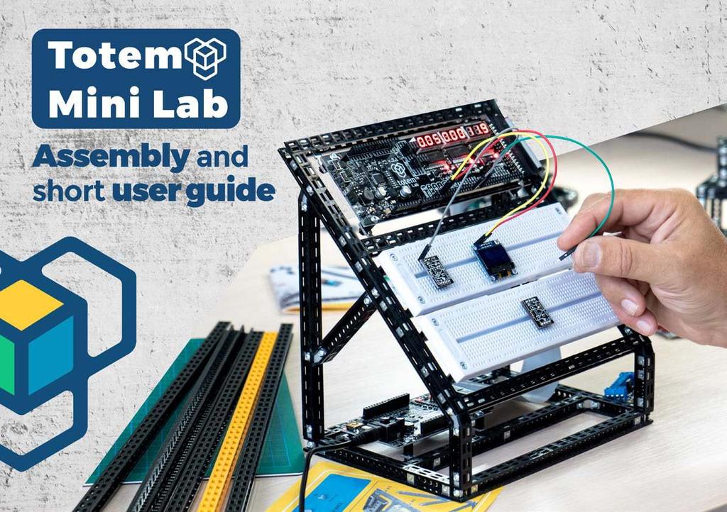
PARTS LIST. Beams: 72x. 16x. 64x. 16x. 12x. 2x Breadboards CYB x TotemDuino 1x LabBoard 1x 30cm 34way Flat Cable 1x Power Supply 12v 1,5A
|
|
|
- Jasmin Harrell
- 5 years ago
- Views:
Transcription
1

2 Totem Mini Lab is a great platform to experiment, learn basics of electronics and Arduino coding. We have made an all-in-one breadboarding and testing unit, that gives you several useful features: Different power supplies : -5v, 3.3v,5v, 12v, and one you can regulate; Measurement of voltages with 3 ranges, outputs from 3 DACs; Easy, short access to all the Arduino I/O pins; All signals available in a single row just above the breadboards.


3 PARTS LIST 72x 8x 2x Breadboards CYB-120 Beams: M3 6mm bolt 12x 6 Nut M3 6x10 C-Bracket 6x M3 12mm bolt 16x Nylon Nut M3 16x Nylon Spacer M3 8mm 8x Beams 4cm Beams 7cm Beams 14cm Beams 16cm Beams 18 cm Beams 20cm 2x 2x 2x 2x 5x 3x 1x TotemDuino 1x LabBoard 1x 30cm 34way Flat Cable 1x Power Supply 12v 1,5A 2-hole Simple 6x L-Twist adj. 8x Use the Totem hyper-magnetic screwdriver to build this model. Single side filler 6x L-Twist adj. mirror 2-hole 45 simple


4 #n x Build step number How many to build. This panel shows what parts you need to build this step. This panel shows what to build in this step. Parts that the sub-assemblies needed. Sub Assembly name Loop view of details A-Z #4 #1 This section shows where the Sub-assembly belongs in the model. This panel shows an exploded view of how to build this step. The #n notifies in which slot in the beam the rectangular nut should be put.


5 1x 1 6x 16x 16x C-Bracket Bolt M3 6mm 2-hole Simple Beams : 2 x 14cm, 3 x 18cm Nut M3 6x10 Nut A #13 #14 #18 18cm #1 #14 14cm #13 #5 18cm Nut Nut #2 #1 #18 18cm 14cm #5 #2 #n means in which slot in the beam you should put the nut. #1 #1


6 2 2x 2x L-Twisted adj. L-Twisted adj. mirror Bolt M3 6mm Nut M3 6x10 A-cont #3 #10 #3 #10 Don t tighten the bolts too much, since you will adjust position a little in the next step.


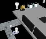
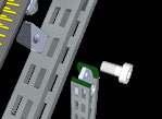
7 3 A-cont M3 6mm bolt 1 x TotemDuino Nylon Spacer M3 8mm Nylon Nut M3 OBS : Nylon Spacers and Nuts may be black! Use these 4 holes: Adjust brackets and towers positions to fit the 4 holes in the TotemDuino. Then tighten the nuts and bolts.


8 4 A-cont 6x 2x 1 1 6x 2-hole 45 simple 2-hole Simple Bolt M3 6mm Nut M3 6x10 Single side filler Beams : 2 x 4cm, 2 x 7cm, 2 x 16cm #16 #16 Hook and snap #16 16cm 7cm 16cm 7cm #6 #6 #4 #1 4cm #1 #4 #1 4cm #1


9 5 12x 12x 6x Bolt M3 6mm Nut M3 6x10 Beams : 3 x 20cm, 2 x 18cm C-Bracket 1xB #20 #2 20cm #19 #20 20cm #14 18cm #14 20cm #2 18cm #1 #2 #18


10 6 2x 2x L-Twist adj. L-Twist adj. mirror Nylon Spacer M3 8mm Nylon Nut M3 Nut M3 6x10 Bolt M3 6mm OBS : Nylon Spacers and Nuts may be black! B cont. #4 #3 #17 Don t tighten the bolts, since you will adjust position a little in the next step. #16


11 7 Bolt M3 6mm 1 x Lab Board B cont. Adjust brackets and towers positions to fit the 4 holes in the Lab Board.


12 8 8x 8x 8x 8x L-Twist ADJ L-Twist ADJ mirror Nylon Spacer M3 8mm Nylon Nut M3 Nut M3 6x10 M3 6mm bolt B cont. #12 #12 #9 #7 #4 #12 #9 #7 Don t tighten the bolts, since you will adjust position a little in the next step. #4


13 9 8x M3 12mm Bolt 2x CY-120 Breadboard B cont. Adjust brackets and towers positions to fit the 8 holes in the 2 Bread Boards.


14 10 6x 6x Nut M3 6x10 M3 6mm bolt Sub assemblies A and B A + B #18 #18 #10 #1 #10 #1


15 11 FINAL STEP Attaching the flat cable. 1x Flat Cable, 34 wires, L=300mm Attach the flat cable to the TotemDuino like this. Attach the flat cable s other end to the LabBoard, by loosening the bolts, so you can lead the Flat Cable up to the connector.
16 Short User Guide 1. Overview SET BUTTONS Use these buttons to set the value you want for the DAC outputs, and the regulated power output VREG. INPUT AND OUTPUTS From these connectors you can patch to your circuit one of the breadboard for measuring and DAC output voltages. SELECT BUTTONS Selects what the LED displays above will show. ARDUINO PORTS ARDUINO PORTS POWER SUPPLIES ARDUINO PORTS

17 2. The TotemDuino Overview USB MINI port Use this port to upload your sketch to the TotemDuino. The standard Arduino SHIELD connectors. This switch selects if your ATmega should run on 3.3v or 5v. See the position guide on the underside of the board. Arduino Ports Connector On this 34way Flat Cable connector, all I/O ports and several power lines are available. Via a Flat Cable the signals are connected to the LabBoard. All I/O signals are protected with diodes and serial resistors, so it would be more difficult to destroy the ATmega microprocessor pins. The Power Input. (V-IN) Apply the power supply to this connector. Range from 9v to 20v. The nominal voltage is 12volts. More than 1 amp is advised. Remember it feeds power to the LabBoard as well. Remark about the power supplies available The TotemDuino generates a 250mA 3.3v and a 1.0A 5v supply available also on the LabBoard.

18 3. Measuring voltages INPUT HEADER Patch into these inputs to measure voltages on your breadboards. There are 3 voltage ranges, +/- 0.5v, +/-5v and +/-50v. DISPLAY The display shows the voltage on the selected input. OBS: When range selected is +/-0.5v, the display shows millivolts. The 2 other ranges shows volts with decimal point. NEGATIVE VOLTAGES A special case is when negative voltages is measured. Then the display blinks, this means negative voltages. We made it so, to give more digits to show, instead of using a - sign. SELECT BUTTONS Selects what the LED displays above will show.


19 4. Setting the DAC outputs SET-BUTTONS Use the SET+ and SET- to step up or down to the desired voltage DAC OUTPUTS HEADER Patch into these outputs to inject a desired voltage to your circuit. It can output xx ma, in the range 0 to 2.5volts. SELECT BUTTONS Selects what which DAC voltage the LED displays above will show. Hold for 2 SEC to go to SET mode. Use the SET+ and SET- to set your desired voltage. DISPLAY The display shows the voltage on the selected output.

20 5. Digital LED indicators, DIG1 and DIG2 DIG1 and DIG 2 Use these 2 inputs to follow a digital signal, input from 3.3v to 5v. DIG1 and DIG2 LEDs These 2 LED simply follows the DIG1 and DIG2 inputs, High=Light, Low=Off
21 6. Frequency measuring START FREQUENCY MEASURE Push the STEP- button for a couple of seconds to start and stop frequency measurement. INPUT DIG1 Use input DIG1 to measure frequency. It can measure digital signals only, 3.3 to 5volts. DISPLAY All 3 displays are used to show frequency. From 0 to approx 750 khz.

22 7. Measuring current consumption RETURN GROUND If you return all grounds to the LabBoard through the GND SHUNT connector, you can measure the current consumption of your whole breadboard circuit. The SHUNT resistor R20 is then used to measure current. Connect SHUNT to INPUT +/-0.5 volt. This input then measures the voltage across the SHUNT resistor. (Don t use this input for anything else then.) DISPLAY #3 will show mamps Use the SELECT button so the LED indicates mamp CIRCUIT NOTE: If you are using some power from the -5volt connector, it s current consumption will in fact be subtracted from the total. It could be misleading sometimes. (The current goes backwards through the shunt somehow) Normally it will not matter.
23 8. Setting the regulated power supply -VOLTAGE REGULATOR CIRCUIT This circuit regulates the V-IN to a desired voltage. Up to 500mA V-REG HEADER From this header you can patch the V-REG to your breadboard. SELECT BUTTON Step to V-REG and hold button for approx 2 seconds. Use the SET- and SET+ buttons to set your desired voltage. Limits: from 3v to V-IN minus 3v DISPLAY Shows the V-REG voltage when selected.


24 9. Power supplies cont -5 V POWER CIRCUIT. This circuit is generating up to 500 ma of -5v. POWER SUPPLIES HEADERS. Patch from these headers to your breadboard design, SELECT BUTTON. Step through 3 values, V-IN, V-REG and the current consumption DISPLAY This diplay can show the voltage of: V-IN that is the same coming from the power supply and V-REG the regulated voltage.
Basic Electronics Course Part 1
 Basic Electronics Course Part 1 Simple Projects using basic components Following are instructions to complete several basic electronic projects Identify each component in your kit Image 1. [There are other
Digital Multimeter: This handheld device is used by this course to measure voltage and resistance we will not use this to measure current or capacitan
 Digital Multimeter: This handheld device is used by this course to measure voltage and resistance we will not use this to measure current or capacitance. For current you will use an analog ammeter and
EGG 101L INTRODUCTION TO ENGINEERING EXPERIENCE
 EGG 101L INTRODUCTION TO ENGINEERING EXPERIENCE LABORATORY 8: DC MOTOR CONTROL DEPARTMENT OF ELECTRICAL AND COMPUTER ENGINEERING UNIVERSITY OF NEVADA, LAS VEGAS GOAL: This section will introduce DC motors
EGG 101L INTRODUCTION TO ENGINEERING EXPERIENCE
 EGG 101L INTRODUCTION TO ENGINEERING EXPERIENCE LABORATORY 11: AUTOMATED CAR PROJECT DEPARTMENT OF ELECTRICAL AND COMPUTER ENGINEERING UNIVERSITY OF NEVADA, LAS VEGAS GOAL: This section combines the motor
Prusa i3 Printer Assembly Guide
 Prusa i3 Printer Assembly Guide Special thanks to Carlos Sanchez and Miguel Sanchez for the graphics. All graphics captured from their great animation: http://www.carlos-sanchez.com/ Prusa3/ For copyright
E D C K R A E T S I D TURNOUT CONTROLLER 8S USER MANUAL
 S I D E T R A C K E D TURNOUT CONTROLLER 8S USER MANUAL INDEX 1. WHAT YOU SHOULD HAVE 3 2. FEATURES OF THE 3 3. WARRANTY 3 4. ABOUT THIS MANUAL 3 5. CONNECTORS AND DESCRIPTIONS 3 6. WIRING 7 6.1. CONTROL
Lab 4.4 Arduino Microcontroller, Resistors, and Simple Circuits
 Lab 4.4 Arduino Microcontroller, Resistors, and Simple Circuits A microcontroller is a "brain" of a mechatronic system that interfaces sensors with a computer. Microcontrollers can perform math operations,
ASSEMBLY INSTRUCTIONS FOR NEW FK109 4 LED Railroad Crossing Flasher Kit WITH ADJUSTABLE FLASHING SPEED CONTROL with 4 Red 3mm Leds
 ASSEMBLY INSTRUCTIONS FOR NEW FK109 4 LED Railroad Crossing Flasher Kit WITH ADJUSTABLE FLASHING SPEED CONTROL with 4 Red 3mm Leds Description: Very easy to build, The FK109 Led Flasher kit makes the perfect
LAVOLTA DC REGULATED POWER SUPPLY BPS-305
 LAVOLTA DC REGULATED POWER SUPPLY BPS-305 USER MANUAL 1 In order to use the power supply better, please read the user manual carefully before using and keeping it properly. Warning: Do not connect any
ARDUINO 2WD SMART ROBOT CAR KIT
 EN ARDUINO 2WD SMART ROBOT CAR KIT P a g e 2 PARTS LIST Please make sure that the following pieces are included in your kit Component Quantity Remarks Arduino Sensor Shield v5.0 1 Align pins using needle
INSTALLER S INSTRUCTIONS FOR TRI-METRIC Battery system monitor, Model TM-2025-RV. Contents
 INSTALLER S INSTRUCTIONS FOR TRI-METRIC Battery system monitor, Model TM-2025-RV revised March 14, 2009 IMPORTANT: The wiring installation for this meter, especially the shunt installation must be performed
LAB 7. SERIES AND PARALLEL RESISTORS
 Name: LAB 7. SERIES AND PARALLEL RESISTORS Problem How do you measure resistance, voltage, and current in a resistor? How are these quantities related? What is the difference between a series circuit and
General Electrical Information
 Memorial University of Newfoundland Department of Physics and Physical Oceanography Physics 2055 Laboratory General Electrical Information Breadboards The name breadboard comes from the days when electrical
SM361 RIG SWITCH CONSTRUCTION MANUAL
 SM361 RIG SWITCH CONSTRUCTION MANUAL Document ver 1, For software release ver 1.1 May 27, 2016 Controls the power of 12V equipment while a vehicle is in use Product Development by: SM361 RIG SWITCH OVERVIEW
Temperature Sensor. Positive + (to 5 volts.) Ground. To A0 To GND Signal. To 5v
 Ground. To A0 To GND Signal. To 5v") Temperature Sensor This system measures the change in temperature and converts it to a colorful thermometer using LEDs. The first time you run the sketch, you will use the serial monitor to find the lowest
Temperature Sensor This system measures the change in temperature and converts it to a colorful thermometer using LEDs. The first time you run the sketch, you will use the serial monitor to find the lowest
VECTRIX VX-2 SERVICE MANUAL. Version 1.0/May 2011 VECTRIX, LLC
 www.vectrix.com CONTENTS SECTION A: Tools 1 Tools Needed SECTION B: Mechanical Parts 1 Front Fairing 2 Front Console Cover 3 Speedometer Cover 4 Front Vertical Panel Cover-Lower 5 Front Vertical Panel
Lab 4: Robot Assembly
 E11: Autonomous Vehicles Lab 4: Robot Assembly In this lab, you ll put together your very own robot! You should have a Mudduino and a chassis, as well as your kit of parts. Now it s time to put them all
Tools you will need: Screwdrivers, Metric Sockets, Hook and Loop Tape or Zip Ties, Shop Light, Wire cutters, Wire crimping tool
 Overview: This guide provides instruction for installing Adventure Wagon s Auxiliary Battery Tray and the charging bundle. Package Contents: Adventure Wagon Battery Tray includes the tray plus mounting
Techgirlz Workshop Scratch and Raspberry Pi
 Techgirlz Workshop Scratch and Raspberry Pi Ruth Willenborg coderdojortp@gmail.com in conjunction with CoderDojo RTP Introduction: Thanks IBM: Raspberry Pi grant to Techgirlz Coderdojo and VMware: Raspberry
The above explanation leaves out a few details, which may frustrate a user. Here are some instructions with pictures to help you be successful.
 When the user exceeds the current capacity of the MY64 multimeter, an internal fuse opens to protect the precision current shunt. Typically this occurs when the user leaves the multimeter in current measuring
FARM MODEL INSTALLATION INSTRUCTIONS
 REAR ATTACHMENT ELECTRIC CONVERSION FARM MODEL INSTALLATION INSTRUCTIONS This page intentionally left blank MICHEL S INDUSTRIES, LTD. p.o. Box 119 St. GREGOR,SK PH: 306.366.2184 em: SALES@MICHELS.CA 1
Assembly Guide for RedBot with Shadow Chassis
 Page 1 of 32 Assembly Guide for RedBot with Shadow Chassis Introduction The SparkFun RedBot is a platform for teaching basic robotics and sensor integration! It is based on the SparkFun RedBoard and fully
Physics Work with your neighbor. Ask me for help if you re stuck. Don t hesistate to compare notes with nearby groups.
 Physics 9 2016-04-13 Work with your neighbor. Ask me for help if you re stuck. Don t hesistate to compare notes with nearby groups. Today we ll build on what we did Monday with batteries and light bulbs.
Arlo Power Distribution Board Kit Rev B (#28996)
") Web Site: www.parallax.com Forums: forums.parallax.com Sales: sales@parallax.com Technical: support@parallax.com Office: (916) 624-8333 Fax: (916) 624-8003 Sales: (888) 512-1024 Tech Support: (888) 997-8267
Web Site: www.parallax.com Forums: forums.parallax.com Sales: sales@parallax.com Technical: support@parallax.com Office: (916) 624-8333 Fax: (916) 624-8003 Sales: (888) 512-1024 Tech Support: (888) 997-8267
(for example A0) on the Arduino you can expect to read a value of 0 (0V) when in its upright position and 1023 (5V) when it is tilted.
 on the Arduino you can expect to read a value of 0 (0V) when in its upright position and 1023 (5V) when it is tilted.") Tilt Sensor Module Tilt sensors are essential components in security alarm systems today. Standalone tilt sensors sense tilt angle or movement. Tilt sensors can be implemented using mercury and roller
Tilt Sensor Module Tilt sensors are essential components in security alarm systems today. Standalone tilt sensors sense tilt angle or movement. Tilt sensors can be implemented using mercury and roller
10260 Retrofit to 10260A Non-Contact Sensor Instructions Kits through -512
 10260 Retrofit to 10260A Non-Contact Sensor Instructions Kits 51404974-501 through -512 Document Number Form: 62-86-33-16D Effective: 3-1-01 Supersedes: 11-00 Summary Retrofitting your 10260 actuator from
PRODUCT MANUAL Desktop LED Dimmer and Receiver
 Product Description Solid Apollo s premium Desktop LED Dimmer is specifically designed as a tabletop dimmer. The elegant and seamless design perfectly complements any modern environment. The dimmer and
Electronic Dynamo Regulator INSTRUCTION MANUAL. COPYRIGHT 2014 CLOVER SYSTEMS All Rights Reserved
 DRM TM DRM-HP TM Electronic Dynamo Regulator INSTRUCTION MANUAL COPYRIGHT 2014 CLOVER SYSTEMS All Rights Reserved INTRODUCTION The Clover Systems DRM is a state-of-the art all-electronic voltage and current
Assembly Manual for ISDR-136-KIT
 Assembly Manual for ISDR-136-KIT ICAS Enterprises Last Updated March 21 st, 2012 This SDR receiver kit is intended for the 136kHz band. The kit utilizes DIP IC components (no SMD) so that even a beginner
Operation and Installation Manual
 Operation and Installation Manual G-Scale Graphics 5860 Crooked Stick Dr. Windsor, CO 80550 970-581-3567 GScaleGraphics@comcast.net www.gscalegraphics.net Revision A: Updated 2/7/2018 Page Overview The
IDC-136II-KIT 136kHz DC RX Assembly Guide
 IDC-136II-KIT 136kHz DC RX Assembly Guide ICAS Enterprises May 2 nd,2016 The IDC-136II-KIT is a 136kHz direct conversion receiver. Most of the SDR software can be used with this receiver. It is quite easy
An Arduino Based. Motorised Pool Cover. Controller
 An Arduino Based Motorised Pool Cover Controller Version.02 December 203 Copyright Chris Gaebler 203 This document or any derivative of it may be freely copied and distributed in any form. Contents Contents...2
MB A 12V/24V DC PROGRAMMABLE DUAL BATTERY ISOLATOR
 MB-3688 120A 12V/24V DC PROGRAMMABLE DUAL BATTERY ISOLATOR User Manual Warning and Precautions MB-3688 is built with corrosion resistant material and the main electronic assembly is well sealed inside
BATTERY BOOSTER SHIELD
 BATTERY BOOSTER SHIELD Introduction The Battery Booster Shield is an add-on for the Arduino that efficiently boosts a lower input voltage (0.65V to 4.5V) up to 5V. It powers the Arduino and peripherals
Feed Rolls 3940 and 3960 PTFH Upper Feed Rolls
 Feed Rolls Upper Feed Rolls 12 3940 and 3960 PTFH 3940 and 3960 PTFH Feed Rolls 46 KEY PART NO. PART NAME QTY. SERIAL NO. 00 REMARKS 1 E52437 BUSHING 1 XX 2 34H353 SPRING PIN 1 X X 3/8" X 1-3/4" 3 24H1480
SEA - BI R D E LE CT R O NI C S, INC th Place N.E., Bellevue, Washington USA Telephone: (425) Telex: SBEI UR
 Telex: SBEI UR") SEA - I R D E LE CT R O NI C S, INC. 1808 136th Place N.E., ellevue, Washington 98005 USA Telephone: (425) 643-9866 Telex: 292915 SEI UR Fax: (425) 643-9954 email: seabird@seabird.com SE P/N 801483 DATE
SEA - I R D E LE CT R O NI C S, INC. 1808 136th Place N.E., ellevue, Washington 98005 USA Telephone: (425) 643-9866 Telex: 292915 SEI UR Fax: (425) 643-9954 email: seabird@seabird.com SE P/N 801483 DATE
Build Your Own Hive Monitor
 Build Your Own Hive Monitor By Nick Lambert 18/09/2017 Page No. 1 www.oldmanortwyning.co.uk Nick Lambert Why build a Hive Monitor? To learn more about your bees and how their hive environment is controlled.
Chapter 2. Battery Charger and Base Assembly
 Chapter 2 Battery Charger and Base Assembly 11 CHAPTER 2. BATTERY CHARGER AND BASE ASSEMBLY 2.1 Section Overview This Lab teaches students how to assemble a Tekbot, in the following steps: Describe the
Micro USB Lamp Kit ESSENTIAL INFORMATION. Version 2.1 DESIGN A STYLISH LAMP WITH THIS
 ESSENTIAL INFORMATION BUILD INSTRUCTIONS CHECKING YOUR PCB & FAULT-FINDING MECHANICAL DETAILS HOW THE KIT WORKS DESIGN A STYLISH LAMP WITH THIS Micro USB Lamp Kit Version 2.1 Build Instructions Before
Job Sheet 6 Installing the Combiner Box
 Job Sheet 6 Installing the Combiner Box The Combiner Box The combiner box used in this course can combine photovoltaic (PV) solar sub-array strings that are up to 150 V DC each and up to 120 A total. Using
DMR 3005 WM ONE ZONE WIRELESS DIMMER RECEIVER
 E363518 DMR 3005 WM ONE ZONE WIRELESS DIMMER RECEIVER 20725 NE. 16 AVE. #A-33 MIAMI, FLORIDA 33179 Tel: (305) 652-2599 Fax: (305) 650-8812 www.lumiron.com Email: sales@lumiron.com 1 Benefits and Features
INSTALLER S INSTRUCTIONS FOR TRI-METRIC Battery system monitor, Models TM-2025-RV and TM-2025-A. Contents
 INSTALLER S INSTRUCTIONS FOR TRI-METRIC Battery system monitor, Models TM-2025-RV and TM-2025-A revised September 2012 IMPORTANT: The wiring installation for this meter, especially the shunt installation
LTX RF LEVEL SENSOR. Instruction Manual
 LTX RF LEVEL SENSOR Instruction Manual FOR MODELS LTX01, LTX02, LTX05 Intempco Document No: LTX - M01 Rev. 1 Issue Date: April 2005 LTX01 RF LEVEL SENSOR USER MANUAL Software Rev : Rev. Date : June 2004
NOTE: Skids, springs, center section, and hardware are located in the push tube box.
 72 HYDRAULIC V-PLOW MOUNTING INSTRUCTIONS BLADE P/N: 4501-0190 PUSH TUBE ASSM P/N: 4501-0191 CUSTOMER MUST RECEIVE A COPY OF THIS INSTRUCTION SHEET AT THE TIME OF SALE NOTE: Skids, springs, center section,
Rear Speaker replacement.
 Rear Speaker replacement. First off you need the right rear speakers. The easy bit is 6x9 and better than a 15W paper cone, the difficult bit is getting a mounting depth under 74mm. Or to be more precise,
Eurocompulsion Camshaft Installation
 Eurocompulsion Camshaft Installation Introduction, please read. The purpose of this article is too assist our customers with installation of a performance camshaft in the Fiat Multiair 1.4 Turbo. The operation
Replacement Tach Board Manual
 Replacement Tach Board Manual 67-74 Dodge and Plymouth Cars that use electronics Internal to the tachometer. Real Time Engineering 19352 Hilton Rd. Springdale, AR 72764 (479) 756-3917 fax Rev8 www.rt-eng.com
Experiment 3: Ohm s Law; Electric Power. Don t take circuits apart until the instructor says you don't need to double-check anything.
 Experiment 3: Ohm s Law; Electric Power. How to use the digital meters: You have already used these for DC volts; turn the dial to "DCA" instead to get DC amps. If the meter has more than two connectors,
Impulse Voltage Test System, Q Structure, kV
 TCDYQ Series Impulse Voltage Test System, Q Structure, 200-3600kV Applications: Shunt reactors Power transformers Distribution transformer Instrument transformers Cables (type tests) Bushings Arresters
SK-10. Features. Solar Charge Controller User Manual. Important Safety Information
 SK-10 Solar Charge Controller User Manual 12V/24V 10Amp Dear Users: Thank you for selecting our product. Please read this manual carefully before you use this product. This product is of cutting edge design,
Batteries. Alkaline - Not ideal, not enough power, expensive, not good for high drain applications.
 Batteries Fortunately, games console systems take in mains power and convert it to DC; which means we can bypass the mains and run the system directly off batteries. There are various types available:
Wiring Diagram 7 Amp 2 Step (7642MC) Ignition Box - No Booster ENGINE BLOCK LOWER LIMIT ARMING WIRE ORANGE GREEN BLACK DISTRIBUTOR LOOM (PRE-MADE)
 Ignition Box - No Booster ENGINE BLOCK LOWER LIMIT ARMING WIRE ORANGE GREEN BLACK DISTRIBUTOR LOOM (PRE-MADE)") Wiring Diagram 7 Amp 2 Step (7642MC) Ignition Box - No Booster IGNITION SWITCH 7 AMP 2 STEP TO TACH 7642MC LOWER LIMIT ARMING WIRE WHITE ENGINE BLOCK DISTRIBUTOR LOOM (PRE-MADE) DISTRIBUTOR COIL BATTERY
Wiring Diagram 7 Amp 2 Step (7642MC) Ignition Box - No Booster IGNITION SWITCH 7 AMP 2 STEP TO TACH 7642MC LOWER LIMIT ARMING WIRE WHITE ENGINE BLOCK DISTRIBUTOR LOOM (PRE-MADE) DISTRIBUTOR COIL BATTERY
DuraWatt DS12VD 140-Watt DC-DC 12 Volt Power Supply Short Form User Manual Version 1.0. Table of Contents
 DuraWatt DS12VD 140-Watt DC-DC 12 Volt Power Short Form User Manual Version 1.0 Table of Contents 1. Getting Started...1 1.1. Introduction...1 1.2. Product Photo...2 1.3. Block Diagram...2 1.4. Included
SMART LAB PUTTING TOGETHER THE
 PUTTING TOGETHER THE SMART LAB INSTALLING THE SPRINGS The cardboard workbench with all the holes punched in it will form the base to the many cool circuits that you will build. The first step in transforming
Electric Circuits. Lab. FCJJ 16 - Solar Hydrogen Science Kit. Next Generation Science Standards. Initial Prep Time. Lesson Time. Assembly Requirements
 Next Generation Science Standards NGSS Science and Engineering Practices: Asking questions and defining problems Developing and using models Planning and carrying out investigations Analyzing and interpreting
QRPGuys Digital Power Port
 QRPGuys Digital Power Port Shown with user supplied battery First, familiarize yourself with the parts and check for all the components. If a part is missing, please contact us and we will send one. You
LAB 3 SeaMATE PufferFish Practice Board
 LAB 3 SeaMATE PufferFish Practice Board Components: Practice Board Kit, (2 resistors, 2 LEDs, 1 DPDT switch, 1 PCB, 1 9-volt battery connector, 2 motor wires color varies) Tools & equipment needed: Safety
Cybex Arc Trainer Owner s & Service Manual. 7 - Service
 7 - Service Table of Contents......... iii Warnings/Cautions All warnings and cautions listed in this chapter are as follows:! WARNING: All maintenance activities shall be performed by qualified personnel.
CONTENTS. This Product is Certified by CANADIAN STANDARDS ASSOCIATION and Bears the Mark:
 This Product is Listed by UNDERWRITERS LABORATORIES INC. and Bears the Mark: This Product is Certified by CANADIAN STANDARDS ASSOCIATION and Bears the Mark: SLATER SCD Installation Instructions For Self-Contained
PB-203A. Powered Proto-Board Instruction Manual
 PB-203A Powered Proto-Board Instruction Manual 10/2009 2 All rights reserved. No Part of this book shall be reproduced, stored in a retrieval system, or transmitted by any means, electronic, mechanical,
Rear Bumper Cover Unpainted ( ):
:") Rear Bumper Cover Unpainted (1999-2004): Tools Required: Ratchet Socket extension 7/16 deep well socket 7/16 wrench 5/16 socket Fastener Removal Tool Offset Phillips screwdriver Extendable magnet (optional
Rear Bumper Cover Unpainted (1999-2004): Tools Required: Ratchet Socket extension 7/16 deep well socket 7/16 wrench 5/16 socket Fastener Removal Tool Offset Phillips screwdriver Extendable magnet (optional
Simple Eurorack Row. Kit Builder's Guide. 4mspedals.com
 Simple Eurorack Row Kit Builder's Guide 4mspedals.com ' Simple Eurorack Row This guide is for building a single-row eurorack case with a power supply. When completed, the case is ready to accept eurorack
OWNERS MANUAL LINK 2000-R IDEAL REGULATOR OPTION
 Copyright 1991-98 Part # 890025 OWNERS MANUAL LINK 2000-R IDEAL REGULATOR OPTION SUPPLEMENT TO THE LINK 2000 OWNERS MANUAL 01/20/98 s THIS DOCUMENT APPLIES TO LINK 2000-R SERIAL NUMBER 2000 AND ABOVE.
BASIC ELECTRICAL MEASUREMENTS By David Navone
 BASIC ELECTRICAL MEASUREMENTS By David Navone Just about every component designed to operate in an automobile was designed to run on a nominal 12 volts. When this voltage, V, is applied across a resistance,
Peg-Harness installation instructions
 Peg-Harness installation instructions I know it s not the easiest thing to do, but PLEASE READ THESE INSTRUCTIONS COMPLETELY so you will understand what you are trying to accomplish before you start drilling
HGM1780. Automatic Genset Controller USER MANUAL. Smartgen Technology
 HGM1780 Automatic Genset Controller USER MANUAL Smartgen Technology Smartgen Technology Co., Ltd No. 28 Jinsuo Road Zhengzhou Henan Province P. R. China Tel: 0086-371-67988888/67981888 0086-371-67991553/67992951
DODGE RAM 2500
 81234007 2014-2015 DODGE RAM 2500 Congratulations - your new LevelTow Helper Springs are quality products capable of improving the handling and comfort of your vehicle. As with all products, proper installation
BREADBOARD PLUGIN POWER SUPPLY # REV3 +5VDC
 BREADBOARD PLUGIN POWER SUPPLY # 400039 REV3 +5VDC INDEX A. Learn Power Supply Design with a hands on approach B. General Information and Features C. Assembled Picture of the Breadboard plug-in power supply
Instruction Manual for the. E-SL 450 Series
 Instruction Manual for the E-SL 450 Series Estate Slide Summary of Functions The Estate Slide is only to be used for vehicular Slide gates in a Class I setting. Class I: A vehicular gate opener (or system)
April 11, 2013 Revision 0. Buffer Pass Unit - J1 Service Manual
 1 2 3 5 6 April 11, 2013 Revision 0 Buffer Pass Unit - J1 Service Manual Application This manual has been issued by Canon Inc. for qualified persons to learn technical theory, installation, maintenance,
Arlo Power Distribution Board Kit Rev B (#28996)
") Web Site: www.parallax.com Forums: forums.parallax.com Sales: sales@parallax.com Technical: support@parallax.com Office: (916) 624-8333 Fax: (916) 624-8003 Sales: (888) 512-1024 Tech Support: (888) 997-8267
Web Site: www.parallax.com Forums: forums.parallax.com Sales: sales@parallax.com Technical: support@parallax.com Office: (916) 624-8333 Fax: (916) 624-8003 Sales: (888) 512-1024 Tech Support: (888) 997-8267
1 of 2 9/4/ :27 AM
 Ford Mustang IAC IAB - Solving your idle problems http://www.muscularmustangs.com/iac.php 1 of 2 9/4/2010 10:27 AM Solving idle problems part 1 - Cleaning your IAC Does your idle rise and fall over and
Happy Friday! Do this now:
 Happy Friday! Do this now: Take all three AA batteries out of your kit, and put (only!) two of them in the holder. (Keep the third one handy.) Take your digital multimeter out of its packaging, as well
Main Fuel Tank #9668 Date 3/17/18 rev. 0. Pic #1 Pic #2. Pic #3. Pic #4. Pic #5 Pic #6
 1045 S. Cherokee Lane Lodi CA 95240 Phone (209)400-7200 Fax (209)943-7923 www.wildhorses4x4.com Note: To assure a completely clean tank, use the large hole to inspect tank for any debris. It is highly
11.1 CURRENT ELECTRICITY. Electrochemical Cells (the energy source) pg Wet Cell. Dry Cell. Positive. Terminal. Negative.
 pg Wet Cell. Dry Cell. Positive. Terminal. Negative.") Date: SNC1D: Electricity 11.1 CURRENT ELECTRICITY Define: CIRCUIT: path that electrons follow. CURRENT ELECTRICITY: continuous flow of electrons in a circuit LOAD: device that converts electrical energy
Date: SNC1D: Electricity 11.1 CURRENT ELECTRICITY Define: CIRCUIT: path that electrons follow. CURRENT ELECTRICITY: continuous flow of electrons in a circuit LOAD: device that converts electrical energy
PRODUCT MANUAL Onyx 2 Zone In-Wall Wireless LED Dimmer and Receiver
 Product Description Main Functions: Control Up to 2 Zones Independently Wireless Control for Quick and Easy Installation Touch Sensitive Dark Glass Surface 50 Foot Wireless Range Soft Touch On/Off Memory
Fanatec GT3RS V1 to GT3RS V2 Tutorial
 Fanatec GT3RS V1 to GT3RS V2 Tutorial by Roy Visser 1 How to update your Fanatec GT3RS V1 wheel to a GT3RS V2 wheel Welcome to this guided and detailed tutorial for upgrading your Fanatec GT3RS V1 wheel
AGELKOM CAP04V-9 Plasma and Oxy Fuel Torch height control for sheet metal cutting machines Height Sensor & Controller
 AGELKOM CAP04V-9 Plasma and Oxy Fuel Torch height control for sheet metal cutting machines Height Sensor & Controller 9 PIN D-SUB INTERFACE CAP 04 CAPACITIVE HEIGHT CONTROLLER IN POSITION CABLE FAULT Description:
General Purpose Flasher Circuit
 General Purpose Flasher Circuit By David King Background Flashing lights can be found in many locations in our neighbourhoods, from the flashing red light over a stop sign, a yellow warning light located
MONGOOSE. Introduction. < blueroomelectronics > Assembly Instructions. Mongoose was designed as an introduction to Mechatronics.
 MONGOOSE Assembly Instructions Introduction Mongoose was designed as an introduction to Mechatronics Page 1 of 12 Before you start The Mongoose is a complex kit and skipping instructions is not advised,
Operation and Installation Manual
 Operation and Installation Manual G-Scale Graphics 4118 Clayton Ct. Fort Collins, CO 80525 970-581-3567 GScaleGraphics@comcast.net www.gscalegraphics.net Revision C: Updated 7/15/2009 Page Overview The
CHAPTER 2. Current and Voltage
 CHAPTER 2 Current and Voltage The primary objective of this laboratory exercise is to familiarize the reader with two common laboratory instruments that will be used throughout the rest of this text. In
BMS16 v cell Lithium Battery Management System
 ZERO EMISSION VEHICLES AUSTRALIA http://www.zeva.com.au Safety Warning Although 8-16 cell lithium battery packs do not involve lethal voltages, they frequently involve dangerous amounts of current and
PID-1500 THERMOELECTRIC & RESISTIVE HEATER TEMPERATURE CONTROLLER INSTRUCTION MANUAL
 LASER DIODE DRIVERS TEMPERATURE CONTROLLERS Simply Advanced Control for Your Cutting Edge Design PID-1500 THERMOELECTRIC & RESISTIVE HEATER TEMPERATURE CONTROLLER INSTRUCTION MANUAL P O Box 865, Bozeman,
Arlo Power Distribution Board Kit (#28996)
") Web Site: www.parallax.com Forums: forums.parallax.com Sales: sales@parallax.com Technical: support@parallax.com Office: (916) 624-8333 Fax: (916) 624-8003 Sales: (888) 512-1024 Tech Support: (888) 997-8267
Web Site: www.parallax.com Forums: forums.parallax.com Sales: sales@parallax.com Technical: support@parallax.com Office: (916) 624-8333 Fax: (916) 624-8003 Sales: (888) 512-1024 Tech Support: (888) 997-8267
8 Channel 5V Optical Isolated Relay Module
 Handson Technology Data Specification 8 Channel 5V Optical Isolated Relay Module This is a LOW Level 5V 8-channel relay interface board, and each channel needs a 15-20mA driver current. It can be used
Electronic Dynamo Regulator INSTRUCTION MANUAL. COPYRIGHT 2014 CLOVER SYSTEMS All Rights Reserved
 DRM TM DRM-HP TM Electronic Dynamo Regulator INSTRUCTION MANUAL COPYRIGHT 2014 CLOVER SYSTEMS All Rights Reserved INTRODUCTION The Clover Systems DRM is a state-of-the art all-electronic voltage and current
BLUE LIGHT FOR DYNACO STEREO 120 OR PAT-4 ROCKER SWITCHES
 BLUE LIGHT FOR DYNACO STEREO 120 OR PAT-4 ROCKER SWITCHES 2012 AkitikA, LLC All rights reserved Revision 1p3 April 18, 2012 Page 1 of 15 Table of Contents Table of Contents... 2 Table of Figures... 2 Section
Wired Real Time GPS Installation Instructions
 Wired Real Time GPS Installation Instructions This page intentionally left blank. TABLE OF CONTENTS 1. Introduction 2 2. Selecting the Mounting Location for the Device. 3 3. Mounting the Device 5 4. Optional
MIC210 Electric Farm Conversion Instructions
 MIC210 Electric Farm Conversion Instructions Note: Apply the supplied Dielectric Lubricant to all wire connections when each wire is hooked up. The Dielectric Lubricant will help to prevent corrosion.
3D PRINTER. Pack 09. Anything you can imagine, you can make! 3D technology is now available for you at home! BUILD YOUR OWN
 BUILD YOUR OWN Pack 09 Anything you can imagine, you can make! 3D PRINTER Compatible with Windows 7 & 8 Mac OS X 3D technology is now available for you at home! www.model-space.com BUILD YOUR OWN 3D PRINTER
EMG SpikerShield v1.2 Instructions
 EMG SpikerShield v1.2 Instructions Prepare yourself. In 2-4 hours, you will have built your own Arduino compatible EMG SpikerBox, so you can control robots and anything you wish with your EMG muscle activity.
Harbach Soft Key (sk-220) Installation Instructions for the Heathkit SB-220
 Installation Instructions for the Heathkit SB-220") Harbach Soft Key (sk-220) Installation Instructions for the Heathkit SB-220 Step-by-Step Instructions with Photos Based on an install by W4HDM Installation & Photos by W4HDM Instructions from http://www.harbachelectronics.com/
Harbach Soft Key (sk-220) Installation Instructions for the Heathkit SB-220 Step-by-Step Instructions with Photos Based on an install by W4HDM Installation & Photos by W4HDM Instructions from http://www.harbachelectronics.com/
M3-ATX 6-24V Intelligent ATX Power Supply
 M3-ATX 6-24V Intelligent ATX Power Supply Installation Guide Version 1.0b P/N M3-ATX-01 Before you start Please take a moment and read this manual before you install the M3-ATX in your vehicle. Often times,
K Wiring and Electronics
 HKBay.com K Wiring and Electronics Written By: HKBay 2017 hkbay.dozuki.com Page 1 of 12 TOOLS: Hex key; ball ended, long arm, 2.5mm (1) PARTS: Arduino Mega (blue) (1) RAMPS board (red) (1) glass tabs (3)
FULL VOLTAGE STARTERS z SIZE 8 SERIES B CONSTRUCTION
 505 z 509 FULL VOLTAGE STARTERS z SIZE 8 SERIES B CONSTRUCTION The movable contacts are carried in stainless steel cages which in turn are mounted in cavities in the molded portion of the cross bar. This
Soldering Pi2Go Lite. Soldering the Line-Follower PCB
 Soldering Pi2Go Lite First check which version of the main PCB you have. It is marked above the left motor "Pi2Go-Lite v1.x". There are minor changes to some parts of the build. v1.0 (initial release)
FlexJet - Flex Cable Replacement
 P/N: 109515R0 14140 NE 200th St. Woodinville, WA. 98072 PH: (425) 398-8282 FX: (425) 398-8383 FlexJet - Flex Cable Replacement Notices: Warning! Ensure that all AC power cables are removed from the printer
DIGITAL TORQUE GAUGE MODEL BTGE-G
 DIGITAL TORQUE GAUGE MODEL BTGE-G OPERATING INSTRUCTION BTGE-G BTGE-G Model To use this product properly and safely, please read this manual carefully before use. If you have any question about the product
ProPass-200 Top Dresser
 Setup Manual Form No. 3365-184 Rev A ProPass-200 Top Dresser Model No. 44700-Serial No. 310000001 and Up Model No. 44701-Serial No. 310000001 and Up Model No. 44704 Model No. 44705 Model No. 44706 Model