CONSTANT TENSION KIT UNINSTALLING
|
|
|
- Martha Bond
- 5 years ago
- Views:
Transcription
 and R20 (470Ω, 1/4W, 5%). Making Room Remove the transport cards from the card cage Remove the MM1200 side panels.")

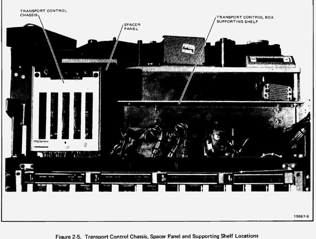
1 CONSTANT TENSION KIT UNINSTALLING Restoration of the Capstan Servo PWA Remove the piggyback board, and de-solder the six wires which connect it to the Capstan Servo PWA. Restoration of the Transport Control PWA Reinstall R18 (470Ω, 1/2W, 5%) and R20 (470Ω, 1/4W, 5%). Making Room Remove the transport cards from the card cage Remove the MM1200 side panels. Remove the control box (the remote) from the MM-1200 by lifting it away from the plastic Velcro retainers, and disconnect the electrical Winchester connector. Pull the armrest and meter panel out as far as the slots in the adjustable sidearms will allow. Then, remove the meter bridge by unfastening the four screws, associated washers, and self-locking nuts (11/32 ), on the slide brackets. Gently bring the left side of the meter panel down and to the right, while setting the right-side bracket to rest on top of the aluminum piece attached to the transport frame. Clamp to secure.


2 Removal of the Tension Controller PWA and Bracket Assembly The bracket holding the Tension Controller PWA extends downward from the control box (remote) shelf, with edge connector J15 on the left. Unfasten the two 8-32 inch screws, to release the whole assembly. Removal of the Control Box Shelf With the tension controller removed, there is now access to the four 8-32 screws holding the transport control box (the remote) shelf. Unfasten the screws and remove the shelf. Release J5 from transport control panel (the back panel) Locate J5 on the operator side of the transport control panel, and disconnect P5 (on the opposite side of the panel). Now release J5 from the panel by pinching the plastic catches together (above and below the connector, from the behind the panel) while pulling connector straight out. This step is performed to allow greater freedom of movement.
. Unscrew and remove the indicator PWA from the panel. Do not reattach the spacer panel at this time.")

3 Removal of the Motor Control Indicator Panel Unfasten the two mounting screws on the motor control indicator panel (located between transport control chassis and transport control box). Unscrew and remove the indicator PWA from the panel. Do not reattach the spacer panel at this time. Free the Transport Control Chassis (Card Cage) Remove the two hex screws from near the top of the transport control chassis on the operator s side. Reach behind the panel, and remove the two Philips screws which secure 2 harness clamps to the frame, and into the bottom of the card cage. Carefully lay the transport control chassis on its side, to expose the edge connectors.

. Pull out as far as necessary for easy access.")
4 Remove J2 connections De-solder/disconnect the harness leads from J2 (the edge connector for the Capstan Servo PWA), and remove the jumper between R and S. The connections are described below: Remove P5 connections Reach behind the transport control panel from the left side of the MM-1200 and grasp connector P5 (unplugged from J5 in an earlier step). Pull out as far as necessary for easy access. Disconnect the four wires coming from the Tension Control harness. The connections are described below:
. Disconnect J16 from the Reel Speed Sensor PWA.")
5 Disconnect J16 from the Reel Speed Sensor PWA Unfasten the two screws securing the PWA bracket to the brake housing, then remove the reel speed sensor assembly from the take-up Motor. Remove the loop-clamp that secures the cable, to the reel speed sensor bracket (bottom of take-up motor). Disconnect J16 from the Reel Speed Sensor PWA. Disconnect P17 Disconnect P17 from J17 on the Motor Control Indicator PWA. This completes the removal of the constant tension kit. Reassembly Return the transport control chassis (card cage) to its upright position and replace the fastening screws. Reinstall the spacer panel (minus the motor control indicator) on the machine. Reattach J5 to the panel, and reconnect it to P5. Mount the transport control shelf on the machine in its original position. Reconnect and install the transport control box (remote) on the shelf. Reattach the meter bridge assembly.
6 Replace the Search to Cue/Timer PWA and the newly modified Capstan Servo and Transport Control PWA's. This completes the reassembly procedure. Final Check and Alignment Check the 15/27 voltage regulator adjustments. Perform a full transport alignment procedure.
7
8
9
10
Carousel Unit User Manual Replacing the Check Stand Motor
 Carousel Unit User Manual Replacing the Check Stand Motor 02/01/2017 1 Table of Contents Tools:... 3 Turn Off Power to the Unit:... 4 Remove Power Switch... 5 Remove Electric Eyes:... 6 Remove POS (Point-Of-Sale)
6th generation (2015+) Mustang Harness Mount Bar Installation Instructions
 Mustang Harness Mount Bar Installation Instructions") R-1180 6th generation (2015+) Mustang Harness Mount Bar Installation Instructions A. Install harness bar 1. Remove front seats. First remove the plastic bolt covers front and rear using a small flat head
R-1180 6th generation (2015+) Mustang Harness Mount Bar Installation Instructions A. Install harness bar 1. Remove front seats. First remove the plastic bolt covers front and rear using a small flat head
Desktop 5.5 Z Axis Retrofit
 Page 1 Kit parts Desktop 5.5 Z Axis Retrofit Carriage plate with stop bolt and Z proximity switch installed Zip ties Spare bolts Spindle mounting plate with stop bolt, spring mount, and rail Z proximity
Replacing the Gear Drive Motor Assembly and GFCI Module for Operation with the Chain Drive Motor Assembly
 Replacing the Gear Drive Motor Assembly and GFCI Module for Operation with the Chain Drive Motor Assembly Kit Contents B00009035-3 Motor Drive Assembly (Return original to CMI) B00007698-8 GFCI Module
Section 5: Parts Replacement
 Section 5: Parts Replacement Should the STAR TRAC 4500 Treadmill experience a problem requiring replacement of a specific part, the following procedures will help and instruct in the replacement of major
3/8 Universal Joint Phillips Head Screwdriver
 Magnetic retrieval tool Pliers 1/4 Ratchet Drive T-35 Torx Socket 3/8 Ratchet Drive 5mm Allen Head Socket Torque Wrench 7-3/8 Drive Extension Flat Head Screwdriver 10mm Socket 8mm Socket 3/8 Universal
LGT-312L E-Z-Go TXT Light Bar Bumper Kit Installation Instructions
 LGT-312L E-Z-Go TXT 2014+ Light Bar Bumper Kit Installation Instructions Caution: Please read through the instructions carefully. Before starting this project, remove the system s positive and negative
INSTALLATION INSTRUCTIONS
 INSTALLATION INSTRUCTIONS Document# 19-0038 2004+ Lotus Elise (Series 2) Rear Clamshell Removal Kit Safely support the vehicle. This is a two-person job. Allow 1 to 2 hours for initial disassembly. Have
BOX LIFT INSTALLATION KIT P/N
 BOX LIFT INSTALLATION KIT P/N 2879733 Application BRUTUS Before you begin, read these instructions twice and check to be sure all parts and tools are accounted for. Please retain these installation instructions
The Go Baby Go Build Manual
 The Go Baby Go Build Manual The step-by-step guide to creating your own Go Baby Go Car 4488 Shockwave Robotics and Pacific University Index 1. List of Mat erials 2. Mechanical Assembly a. Installing the
J2 Remove sound insulation/knee guard 1 and side panel 2 on center console
 J1 Preparations Drive car forward on a level surface so that wheels are straight. Disconnect battery negative lead. Turn ignition key to position 1 so that steering lock is off. J2 Remove sound insulation/knee
TESLA MODEL S REAR UNDER SPOILER & DIFFUSER SYSTEM
 TESLA MODEL S Thank you for purchasing your Unplugged Performance Rear Under Spoiler & Diffuser System for the Tesla Model S! Please read this manual carefully prior to installation. REAR UNDER SPOILER
INSTALLATION INSTRUCTIONS FORD SUPER DUTY NOTE: (Vehicle Retains Tow Hook) PART # P3064
 PART # P3064") INSTALLATION INSTRUCTIONS 2011-14 FORD SUPER DUTY 250-550 NOTE: (Vehicle Retains Tow Hook) PART # P3064 PARTS LIST: Qty Description Qty Description 1 Grill Guard 2 10mm x mm Hex Bolts 1 Driver/Left Lower
INSTALLATION INSTRUCTIONS 2011-14 FORD SUPER DUTY 250-550 NOTE: (Vehicle Retains Tow Hook) PART # P3064 PARTS LIST: Qty Description Qty Description 1 Grill Guard 2 10mm x mm Hex Bolts 1 Driver/Left Lower
MINI Smartphone Mount Pro Series Ver 1.1 CRMC-1000-R130. Instructions for both the XL Scissor and XXL Clamshell Cradles for Gen 2 MINIs.
 MINI Smartphone Mount Pro Series Ver 1.1 CRMC-1000-R130 Instructions for both the XL Scissor and XXL Clamshell Cradles for Gen 2 MINIs 1 of 5 Overview XL Scissor and XXL Clamshell Cradles for Gen 2 MINIs
Main Cover and Paper Input Assembly removal
 Main Cover and Paper Input Assembly Remove the toner cartridge. Remove memory door (HP LaserJet 5L and 6L). CAUTION Remove the memory door first (HP LaserJet 5L and 6L). The door will break if you remove
Bulletin Information Model Year(s) Affected
 Affected") Date Issued Bulletin Information Model Year(s) Affected Model(s) Affected TSB # 1/27/06 2005 Present LADB, EXDP 258 Systems Affected Air Conditioning & Heating Electrical Components Appliances & Accessories
Date Issued Bulletin Information Model Year(s) Affected Model(s) Affected TSB # 1/27/06 2005 Present LADB, EXDP 258 Systems Affected Air Conditioning & Heating Electrical Components Appliances & Accessories
The world's first Bolt in Only stress bar for VW Mk 4 Chassis. Installation Manual V1.0.
 The world's first Bolt in Only stress bar for VW Mk 4 Chassis Installation Manual V1.0 www.yarrowsport.com Tools Needed: 1. 17mm, 10mm sockets and ratchet with 3inch extension 2. 10mm box end wrench 3.
DEFINITIONS OF SAFETY TERMS DANGER indicates an imminent hazard. If you fail to avoid this hazard, it WILL cause death or serious injury.
 CRUIS N EXOTICA S E C T I O N THREE Service SAFETY INSTRUCTIONS The following safety instructions apply to operators and service personnel. Read these instructions before servicing or preparing the Video
Sherco Motorcycle Assembly Instructions
 Sherco Motorcycle Assembly This manual is intended to be used as an assembly guide for the Sherco 1.25 2.9 Trials Motorcycles. The motorcycle shown in the pictures is a new 2002, 2.9, the one that you
Wildcat System Instructions
 Wildcat System Instructions NOTE: Most steps contained in these instructions will need to be repeated on the other side of the vehicle. Prior to assembly of windshield it is necessary to establish what
Z-Truck (Vertical Moving) Z-truck Flag. Y-Truck (Horizontal Moving) FIGURE 1: VIEW OF THE Z-TRUCK. Flexshaft Assembly
 Z-truck Flag. Y-Truck (Horizontal Moving) FIGURE 1: VIEW OF THE Z-TRUCK. Flexshaft Assembly") Checking and Replacing the AC Motor To remove and replace the AC Motor you will need the following tools: #2 Phillips screwdriver (magnetic tip preferred) Removing the AC Motor 1. Ready the machine by
Checking and Replacing the AC Motor To remove and replace the AC Motor you will need the following tools: #2 Phillips screwdriver (magnetic tip preferred) Removing the AC Motor 1. Ready the machine by
by B6 Boost Volkswagen -> (46) Golf & Jetta V (13) Passat B6 (11) Passat B5.5 (4) Phaeton (8) Eurovan (7) Touareg (3) Audi
 Golf & Jetta V (13) Passat B6 (11) Passat B5.5 (4) Phaeton (8) Eurovan (7) Touareg (3) Audi") 1 of 10 Top» Volkswagen» Passat B6» European Cup Holder DIY Installations European Cup Holder by B6 Boost Volkswagen -> (46) Golf & Jetta V (13) Passat B6 (11) Passat B5.5 (4) Phaeton (8) Eurovan (7) Touareg
1 of 10 Top» Volkswagen» Passat B6» European Cup Holder DIY Installations European Cup Holder by B6 Boost Volkswagen -> (46) Golf & Jetta V (13) Passat B6 (11) Passat B5.5 (4) Phaeton (8) Eurovan (7) Touareg
LGT-311L Bumper LED Light Kit EZ-Go RXV Installation Instructions
 LGT-311L Bumper LED Light Kit EZ-Go RXV Installation Instructions Caution: Please read through the instructions carefully. Before starting this project, remove the system s positive and negative connections
Lokar Cable Operated Sensor Kit Installation Instructions For Ford C4 and C6
 Lokar Cable Operated Sensor Kit Installation Instructions For Ford C4 and C6 Building American Quality With A Lifetime Warranty! TOLL FREE 1-877-469-7440 tech@lokar.com www.lokar.com Lokar Cable Operated
Jeep JK Wrangler XHD Rear Tire Carrier
 Contents: 1. Frame (1) 2. Pivot Mount (1) 3. Latch Mount (1) 4. Lug Nuts (3) 5. Catch Pin (1) 6. M12 Washer (18) 7. M12 x 30 Hex Bolt (14) 8. Brake Light Mount (1) 9. Snap Ring (1) 10. Rub Strip (1) 11.
Dash Procedure (Dash Cluster Corvette) for color upgrade
 for color upgrade") Dash Procedure (Dash Cluster 1984-1989 Corvette) for color upgrade Chapter 1 Please read all instructions before proceeding. 1. Disconnect negative battery cable. 2. Use small flat blade screw driver to
Dash Procedure (Dash Cluster 1984-1989 Corvette) for color upgrade Chapter 1 Please read all instructions before proceeding. 1. Disconnect negative battery cable. 2. Use small flat blade screw driver to
LOW, MID, HIGH RISE PRO-TAPER HANDLEBAR WITH HEATED GRIPS KIT
 LOW, MID, HIGH RISE PRO-TAPER HANDLEBAR WITH HEATED GRIPS KIT P/N 2881235; 2881236; 2881237 APPLICATION All AXYS and PRO RIDE chassis with stock Pro-Taper Bar BEFORE YOU BEGIN Read these instructions and
1967 (Late) CORVETTE STANDARD (NON-ADJUSTABLE) STEERING COLUMN DISASSEMBLY & REPAIR INSTRUCTIONS PAPER #2
 CORVETTE STANDARD (NON-ADJUSTABLE) STEERING COLUMN DISASSEMBLY & REPAIR INSTRUCTIONS PAPER #2") Last Revision: 03SE2012 1967 (Late) - 1968 CORVETTE STANDARD (NON-ADJUSTABLE) STEERING COLUMN DISASSEMBLY & REPAIR INSTRUCTIONS PAPER #2 Disassembly and Repair Instructions Addressed in this Paper Degree
Last Revision: 03SE2012 1967 (Late) - 1968 CORVETTE STANDARD (NON-ADJUSTABLE) STEERING COLUMN DISASSEMBLY & REPAIR INSTRUCTIONS PAPER #2 Disassembly and Repair Instructions Addressed in this Paper Degree
Service Manual Mozart Fireplace
 Service Manual Mozart Fireplace Model Numbers: CFP3913 REV PCN DATE 00 11637 Sep 23, 09 Dimplex North America Limited 1367 Industrial Road Cambridge ON Canada N1R 7G8 1-888-346-7539 www.dimplex.com In
How to remove and replace the Foonf/Fllo fabric
 How to remove and replace the Foonf/Fllo fabric Remove Headrest Locate the Troubleshooting Tool behind the manual on the back of the car seat, as shown in Figure 1. Raise Headrest to highest position by
SERVICE MANUAL Model: SF-INS30-BK - Instructions -
 SERVICE MANUAL Model: SF-INS30-BK - Instructions - NOTICE! DO NOT discard any hardware while servicing. It must be reused. This manual will assist a qualified service technician in the replacement of parts.
RS5mesh style Grille. Audi A5/S5. Installation Instructions. pre-facelift ES best viewed in Acrobat Reader
 Audi A5/S5 pre-facelift RS5mesh style Grille Installation Instructions ES2627648 This tutorial is provided as a courtesy by ECS Tuning. best viewed in Acrobat Reader Proper service and repair procedures
Written By: Walter Galan
 Replace the battery on your iphone 4S. Written By: Walter Galan ifixit CC BY-NC-SA www.ifixit.com Page 1 of 10 INTRODUCTION Replacing the battery on the iphone 4S requires minimal disassembly. If your
Lokar Cable Operated Sensor Kit Installation Instructions
 Lokar Cable Operated Sensor Kit Installation Instructions For GM TH350, TH400, TH200, 200-4R, 700-R4, 4L60 (and 4L60E, 4L80E with Long Selector Shaft) Index Cable Stop Lokar Cable Operated Sensor Kit Installation
Disassembling and Assembling
 Disassembling and Assembling How to disassemble and assemble the controller box 1. Disassembling of controller box Phillips screwdriver, 8# wrench, scissors or penknife. 1) First dismantle the rear bottom
INSTALLATION INSTRUCTIONS FOR THE TOMAHAWK ELECTRIC REVERSE
 INSTALLATION INSTRUCTIONS FOR THE TOMAHAWK ELECTRIC REVERSE LAST UPDATED: April 2018 Thank you for choosing the Motor Trike Electric Reverse. We ask that you read the directions before you start and follow
LG G5 REPAIR GUIDE. Version Edition
 LG G5 REPAIR GUIDE Version 1 2016 Edition LG G5 REPAIR GUIDE LCD AND DIGITIZER REPLACEMENT RiAna Soto Repair Training Specialist rsoto@cellairis.com FOR EVERY REPAIR MAKE SURE TO COMPLETE, INITIAL, AND
Galaxy Note 5 Glass/Lcd REPAIR GUIDE. Version Edition
 Galaxy Note 5 Glass/Lcd REPAIR GUIDE Version 1 2016 Edition Samsung Galaxy Note 5 Glass/LCd REPAIR GUIDE RiAna Soto Repair Training Specialist rsoto@cellairis.com FOR EVERY REPAIR MAKE SURE TO COMPLETE,
Lokar Cable Operated Sensor Kit Installation Instructions
 Lokar Cable Operated Sensor Kit Installation Instructions For GM TH350, TH400, TH200, 200-4R, 700-R4, 4L60 (and 4L60E, 4L80E with Long Selector Shaft) Building American Quality With A Lifetime Warranty!
Replacing the Batteries on an Acorn 180 or Bison 80 Stairlift
 Replacing the Batteries on an Acorn 180 or Bison 80 Stairlift Remove the front cover by unscrewing the two philips screws and removing them. Find the two long batteries on either side of the circuit board.
Pinch Valve Replacement (Enzymes)
") To replace the Enzyme Pinch Valve on the ANKOM Dietary Fiber Analyzer, follow the steps below. Note: The following items will be sent in a replacement package: New Enzyme Pinch Valve (47), three 6 tubes,
To replace the Enzyme Pinch Valve on the ANKOM Dietary Fiber Analyzer, follow the steps below. Note: The following items will be sent in a replacement package: New Enzyme Pinch Valve (47), three 6 tubes,
NETBOOK CART DIVIDER WIRING INSTRUCTIONS Extra cord
 NETBOOK CART DIVIDER WIRING INSTRUCTIONS Extra cord Ensure there is slack here Lay divider flat on work surface. Lay laptop and power brick on top of divider, with the computer end of the power wire towards
Vibrator Kit. Stainless Steel & Poly Hopper Spreaders with FLEET FLEX Electrical System
 October 1, 2016 Lit. No. 95098, Rev. 01 PARTS LIST Vibrator Kit Stainless Steel & Poly Hopper Spreaders with FLEET FLEX Electrical System 5 7 6 9 8 4 1 10 2 3 99504 1 Vibrator Kit Item Part Qty Description
Miata High Flow Air Inlet Assembly Part No
 1999-05 Miata High Flow Air Inlet Assembly Part No. 56502 Installation of this assembly on a Miata equipped with the factory shock tower brace requires the use of the RB Mounting Bracket Kit (Part No.
Coil Spring Conversion Kit
 Coil Spring Conversion Kit Land Rover Discovery 3 INTRODUCTION Thank you for your purchase of a coil spring conversion kit from Dunlop Systems and Components Limited, suitable for the Land Rover Discovery
Jazzy 1122 Wheelchair Trainer: Owner s Manual
 Jazzy 1122 Wheelchair Trainer: Owner s Manual KEYED IGNITION The keyed Ignition allows for more control and safety over your wheelchair trainer. With the trainer being inoperable without the key engaged
WOC & WOC Top & Back Installation Instructions
 Shown with optional Sun Roof WOC-900500-2 & WOC-900501-2 Top & Back Installation Instructions Install Order! Heater Door System Wiper on to Windshield Windshield Rear Panel Top Panel Tools needed: 5/16
Retrofit Steering Column
 Retrofit Steering Column INSTALLATION INSTRUCTIONS for 1974-77 Bronco FOR PART NUMBER S: 1130845010, 1130845020, 1130845051, 1130855010, 1130855020, 1130855051, 1170845010, 1170845020, 1170845051, 1170855010,
2017+ L5P Duramax 3 ½ Down Pipe & EGR Fix Kit
 2017+ L5P Duramax 3 ½ Down Pipe & EGR Fix Kit Covers installation of PN s: WCF100630, WCF100829 Note: This Kit is for off road competition use only! Off Road Competition Use Tuning & Exhaust System is
INSTALLATION INSTRUCTIONS CATCH CAN KIT
 INSTALLATION INSTRUCTIONS CATCH CAN KIT FORD FIESTA ST Document: 19-0175 Support: info@radiumauto.com STEPS 1-14 COVER THE PCV SIDE CATCH CAN KIT (P/N: 20-0377) STEPS 15-35 COVER THE CRANKCASE CATCH CAN
V6 Mustang BBK Long Tube Headers and Shorty X-Pipe:
 2011-2012 V6 Mustang BBK Long Tube Headers and Shorty X-Pipe: Time Required: Approximately 9 hours w/ 3 installers (highly recommended having help during install); process will be much faster with a lift
This LED flashtube kit covers models 400, 404, 500, 504, 600, 680 & 506.
 L.E.D. INSTRUCTIONS I D T S O T U B I R M O C R Y N A P Kit contains: This LED flashtube kit covers models 400, 404, 500, 504, 600, 680 & 506. For the power supply: 1-LED power supply circuit board, 2
REARVIEW MIRROR AND BACKUP CAMERA KIT
 REARVIEW MIRROR AND BACKUP CAMERA KIT P/N 2881483 APPLICATION Verify accessory fitment at Polaris.com. BEFORE YOU BEGIN Read these instructions and check to be sure all parts and tools are accounted for.
RC4WD Diablo Instruction Manual
 Version 1.1 RC4WD Diablo Instruction Manual Thank you for your purchase. Welcome to the RC4WD family. This kit is a combination of many specially engineered and manufactured parts. Enjoy your build. This
NPD to FID conversion on SRI 8610C or 310C GC July2012
 July2012 Unplug GC from wall power The SRI 8610C GC is shown at right. The NPD detector will be located at the right side of the column oven covered with an insulated aluminum box. Remove the single screw
TRW STEERING COLUMN MODELS CA (TILT/TELESCOPIC) AND CT (TILT ONLY) CAM REPLACEMENT KIT
 AND CT (TILT ONLY) CAM REPLACEMENT KIT") SERVICE BULLETIN (Not applicable to Mack Trucks Australia) NUMBER: SB-412-005 DATE: 6/28/02 MODEL: CX, CV, CH, CL TRW STEERING COLUMN MODELS CA (TILT/TELESCOPIC) AND CT (TILT ONLY) CAM REPLACEMENT KIT
SERVICE BULLETIN (Not applicable to Mack Trucks Australia) NUMBER: SB-412-005 DATE: 6/28/02 MODEL: CX, CV, CH, CL TRW STEERING COLUMN MODELS CA (TILT/TELESCOPIC) AND CT (TILT ONLY) CAM REPLACEMENT KIT
MK7 GTI Electronic Folding Mirror Conversion
 MK7 GTI Electronic Folding Mirror Conversion 01 Mirror and Switch Installation 1. Using a soft pry tool remove the trim panel on the driver side door handle. 02 2. Remove 2 T-30 torx screws. 03 3. On the
Part # SuperFlow 450 Regulator Parts Upgrade Kit
 KIRBY MORGAN Kirby Morgan Dive Systems, Inc. Part #525-757 SuperFlow 450 Regulator Parts Upgrade Kit Part Number Description Qty 205-020 Inlet valve Assembly 1 210-055 O-ring 2 505-088 Adjustment Knob/Packing
PARTS LIST. REPLACEMENT PARTS and ACCESSORIES PREPARATION VN1600. PREPARATION VN1500D and VN800B
 INSTALLATION AND OWNER S MANUAL Light Bar N925 for Installation to: Kawasaki VN1500D&E and VN800B Pages 1,2,3 and 5 Kawasaki VN1600 Pages 1, 4 and 5 PARTS LIST QTY. PART NO. DESCRIPTION 1 N925 Light Bar
BX-308 BAM-1020 SERVICE TOOL KIT MANUAL
 BX-308 BAM-1020 SERVICE TOOL KIT MANUAL Met One Instruments, Inc 1600 Washington Blvd. Grants Pass, Oregon 97526 Telephone 541-471-7111 Fax: 541-471-7116 BX-308-9800 Copyright 2008 Met One Instruments,
Installation and Service Manual
 RAVE Star Lift Installation and Service Manual WARNING! STRICT ADHERENCE TO THESE INSTALLATION INSTRUCTIONS is required and will promote the safety of those installing this product, as well as those who
INSTALLATION INSTRUCTIONS PART NUMBER:
 Equipped with AEM Dryflow Filter No Oil Required! INSTALLATION INSTRUCTIONS PART NUMBER: 21-447 1998-2001 CHEVROLET Cavalier L4-2.2L Manual trans. requires 20-455 C.A.R.B. E.O. # D-670 2000-2002 PONTIAC
Outside Rear View Mirror, Remove and Install
 102989Outside Rear View Mirror, and file://c:\program Files\cosids\DATA\TMP\00102989.rtf.html Page 1 of 2 Outside Rear View Mirror, and 1. Move sash window downwards 2. Detach panel for front door inside
Manipulators. Example 1: The Claw
 Manipulators With these examples we will demonstrate some basic designs to accomplish each of the game piece challenges involved in the 2018 FIRST Global game Energy Impact to: 1. Collect fuel cubes and
INSTALLATION INSTRUCTIONS
 AUTOMOTIVE PRODUCTS, INC. INSTALLATION INSTRUCTIONS ULTIMATE BULL BAR APPLICATION: 2017 Ford F-250/350 PART NUMBER: 32-3900, 32-3905, 32-3900L, 32-3905L ITEM QUANTITY DESCRIPTION TOOLS NEEDED 1 1 ULTIMATE
Installation Bulletin Number: IB-5111 Rev: A Date: Feb 2014 Affected Parts: K
 Replacement of the Potential Relay UNIT ONLY TO BE SERVICED BY QUALIFIED PERSONNEL The following Safety Procedures Must Be Followed! Prior to performing any electrical work, the system must be disabled
INSTALLATION INSTRUCTIONS
 INSTALLATION INSTRUCTIONS Accessory Application Publications No. BII 37612-38949 2008 MDX Issue Date FEB 2008 PARTS LIST Steering wheel 1. Make sure you have the anti-theft codes for the radio and navigation
Hydraulic Oil Cooler. Assembly Instructions (Originating w/serial Number )
") Hydraulic Oil Cooler Case 465 Skid Steer Assembly Instructions (Originating w/serial Number 50-101) Model Number: Serial Number: Date of Purchase: Specialized Equipment, Inc. 650 So. Main Street - PO Box
Hydraulic Oil Cooler Case 465 Skid Steer Assembly Instructions (Originating w/serial Number 50-101) Model Number: Serial Number: Date of Purchase: Specialized Equipment, Inc. 650 So. Main Street - PO Box
INSTALLATION MANUAL. Level of Difficulty. Parts List. Product Image. Tools Required. Notes and Maintenance. Torque Specifications.
 INSTALLATION MANUAL Parts List 1 Bull bar 2 Upper frame mounting bracket 1 Driver / left lower frame mounting bracket 1 Passenger / right lower frame mounting bracket 2 Button head bolt, 6mm 4 Flat washer,
Replacing the Batteries in the Fortress LI 660
 Replacing the Batteries in the Fortress LI 660 This FTS describes how to replace the batteries in Fortress LI 660 units. Batteries should be replaced by a qualified technician. If you have any questions
LEXUS CT 200h ILLUMINATED DOOR SILLS Preparation
 Preparation Part Number: PT922-89100 Kit Contents Item # Quantity Req'd. Description 1 1 Door Sill, Front Right Hand 2 1 Door Sill, Front Left Hand 3 1 Door Sill, Rear Right Hand 4 1 Door Sill, Rear Left
Maintenance Supplies
 Maintenance Supplies 7. 8. 6. 15. 14. 13. 12. 10. 9. 2. 3. 5. 4. 11. 1. 1. TU-3 shown for demonstration purposes 2. Teflon tape 3. Center punch 4. 5/32 punch 5. 1/4 punch 6. 3/8 punch 7. Breaker bar with
P3066 INSTALLATION MANUAL
 P3066 INSTALLATION MANUAL Parts List 1 Grille guard 1 Driver / left frame bracket Level of Difficulty Moderate Scan for helpful install tips 1 Passenger / right frame bracket 1 Driver / left top bracket
Porsche L and 3.6L Unichip PnP Installation Instructions
 Porsche 996 3.4L and 3.6L Unichip PnP Installation Instructions and Warranty Information v1.0, 1 June 2007 Tools Required 10mm socket, ¼-inch or 3/8-inch ratchet, 6-inch ratchet extension, and a 10mm combination
INSTALLATION INSTRUCTIONS
 INSTALLATION INSTRUCTIONS Accessory Application 2013 MDX Publications No. BII 13440 Issue Date JULY 2012 PARTS LIST INSTALLATION Steering wheel 2 TORX bolts Client Information: The information in this
INSTALLATION INSTRUCTIONS
 INSTALLATION INSTRUCTIONS Accessory P/N 08U97-TX4-200 Application 2016 RDX Publications No. VERSION 1 Issue Date APRIL 2015 PARTS LIST Steering wheel Illustration of the Steering Wheel in the Vehicle 2
ECO# 1801 REVISION# 000 ES DATE
 SmokeShield Elevator ECO# 1801 REVISION# 000 ES 10-458 DATE 08/25/2018 ECO# 1801 REVISION# 000 ES 10-458 DATE 08/25/2018 Section 1 Table of Contents Section 2 Safety Check List 2 Section 3 Freight Receiving
X.L. BAND W/ SPRING ASSIST INSTRUCTION MANUAL
 PARTS LIST X.L. BAND W/ SPRING ASSIST INSTRUCTION MANUAL (2) Bands (1) Handle assembly (2) Side hinge assemblies (1) Left rear hinge assembly (1) Right rear hinge assembly (2) front spring s (2) rear spring
2017 Current Ford SuperDuty Adaptive Cruise Control Relocation Bracket Installation Instructions
 2017 Current Ford SuperDuty Adaptive Cruise Control Relocation Bracket Installation Instructions PREPARATION 1. Disconnect the negative terminal on the battery. Park the vehicle on level ground and set
INSTRUCTIONS XL-518. ISOFIX CAR SEAT (with top tether) Group 1,2,3
 Group 1,2,3") INSTRUCTIONS XL-518 ISOFIX CAR SEAT (with top tether) Group 1,2,3 INSTRUCTIONS: PLEASE READ CAREFULLY AND KEEP FOR FUTURE REFERENCE. YOUR CHILD S SAFETY MAY BE AFFECTED IF YOU DO NOT FOLLOW THESE INSTRUCTIONS.
INSTRUCTIONS XL-518 ISOFIX CAR SEAT (with top tether) Group 1,2,3 INSTRUCTIONS: PLEASE READ CAREFULLY AND KEEP FOR FUTURE REFERENCE. YOUR CHILD S SAFETY MAY BE AFFECTED IF YOU DO NOT FOLLOW THESE INSTRUCTIONS.
Installation Instructions for Chevrolet C5 Corvette Lingenfelter High Flow Fuel Pump Module
 Installation Instructions for 1997-2003 Chevrolet C5 Corvette Lingenfelter High Flow Fuel Pump Module PN: L710650197 Lingenfelter Performance Engineering 1557 Winchester Road Decatur, IN 46733 (260) 724-2552
Installation Instructions
 Installation Instructions Transverse K04 Tools Required Jack and jack stands Drain pan for coolant and oil 3" and 6" extensions Channel locks 7mm, 8mm, 10mm, 11mm, 12mm, 13mm, and 16mm sockets Oxygen sensor
ASSEMBLY INSTRUCTIONS FOR CHARGER AND THE BOSS QUICK ATTACH GRASS BAGGER
 ASSEMBLY INSTRUCTIONS FOR CHARGER AND THE BOSS QUICK ATTACH GRASS BAGGER \ \ \ \ ~\ P P-12102 (7/2005) TABLE OF CONTENTS SECTION PAGE WARNING 1 BLOWER PULLEY INSTALLATION 2 ENGINE GUARD REMOVAL BOSS 3
INSTALLATION INSTRUCTIONS ELEVATION FRONT BUMPER 2018 FORD F150
 INSTALLATION INSTRUCTIONS PARTS LIST: 1 Elevation Bumper Assembly 28 12mm x 37mm x 3mm Flat Washers 1 Driver/Left Frame Mounting Bracket 4 12mm Lock Washers 1 Passenger/Right Frame Mounting Bracket 12
Benefit ER200 II Manual ROWER MACHINE
 Benefit ER200 II Manual 94102 ROWER MACHINE Important: Please locate your serial number and record in the box below for service support purposes. Serial number here: ER200 Assembly Diagram EXPLODED DIAGRAM
Service & Maintenance
 Service & Maintenance Amplifier Monitor LEDs & Tubes (Wall-Rock-PV) Translucent Panel (Wall-Rock-PV) Glass Panel (Rock-Star) Fans & Filter G2-1 External Peavey Amplifier) Amplifier Removal 1. Disconnect
Audi B8 A4/5, S4/5 and RS5 Coilover Installation Instructions
 Audi B8 A4/5, S4/5 and RS5 Coilover Installation Instructions This tutorial is provided as a courtesy by ECS Tuning. Proper service and repair procedures are vital to the safe, reliable operation of all
2015+ WRX COLD AIR INTAKE PSP-INT-325BK & PSP-INT-325RD
 Vehicle Fitment Chart: 2015-18 SUBARU WRX H4-2.0L Turbo 2015+ WRX COLD AIR INTAKE PSP-INT-325BK & PSP-INT-325RD 2017-09-05 Thank you for purchasing this PERRIN product for your car! Installation of this
This information covers procedures for replacing the sealant for the crankshaft cover on the Volvo D16F engine.
 Volvo Trucks North America Greensboro, NC USA DService Bulletin Trucks Date Group No. Page 1.2008 216 50 1(17) Sealant Crankshaft Cover, Replacement D16F Sealant Crankshaft Cover, Replacement W2005773
iphone 5s Front Panel Replacement
 iphone 5s Front Panel Replacement Replace the cracked or broken screen on your iphone 5s. Note: DIY at your own risk. New beginner must be careful, screens got problems mostly due to wrong installation
Ford C6 Automatic Trans Mount Shifter Installation Instructions
 Ford C6 Automatic Trans Mount Installation Instructions Building American Quality With A Lifetime Warranty! TOLL FREE 1-877-469-7440 tech@lokar.com www.lokar.com Ford C6 Automatic Trans Mount Installation
BOSTROM SPRINTER SEAT INSTALLATION
 Note: The following is just a suggested procedure for installation, not necessarily the exact method for all Sprinter vans 1. Inboard Seatbelt removal (Buckle Side): 1.1. Unscrew the fastener at the connection
Supply Valve Replacement
 This procedure is to help facilitate the replacement of the25.1-25.4 supply valves. Solenoid Supply Valves Note: You will need the following tools: Socket Wrench with extension and a 3/8 Socket Size 1
R11B EN R11A EN. RackCDU. Service Manual. Edition August 2016 Page 1 of 24 V /8
 R11B-1528-02EN R11A-0555-03EN Service Manual - English RackCDU Service Manual Edition August 2016 Page 1 of 24 Version history Issue number Reason for update 1.0 / December 2015 Initial release 2.0 / February
INSTALLATION INSTRUCTIONS
 INSTALLATION INSTRUCTIONS PARTS LIST 1 Stage 5 Pro Tuner Module 1 USB Cable 1 Installation Guide 1 Velcro 1 Alcohol swab 1 O2 Optimizer 1 Posi-tap *** For Racing use only. Use of the Stage 5 Pro Tuner
P-600. Technical Manual. Troubleshooting Repairs Replacements
 P-600 Technical Manual Troubleshooting Repairs Replacements Table of Contents P-600 Lift Symptoms and Problems Finding the Problem Before Getting Inside 3 Pneumatic Systems 4 Electrical Systems 5 Mechanical
Model EL8500 Series. Bagless Upright. Assembly/Disassembly Guide 1
 Model EL8500 Series Bagless Upright Assembly/Disassembly Guide 1 Table Of Contents Parts Removal / Installation Guide Belt & Brushroll Section A Page 3 Hood Assembly Section B Page 3 Main PCB Board Section
Instruction Sheet IS Date: 8/6/2013
 Instruction Sheet Date: 8/6/2013 Bulletin #: Subject: 072709/072710/072711/072811, Belt Keeper Update Kit Purpose: To instruct Lastec personnel Model Numbers: 3300, 3600, 3380, 3680, 4520 Serial Numbers:
Bottom Mount Seat Mount Installation & Wiring Instructions
 E81/E87/E90/E91/E92/F22/F30/F31/F32/F80/F82/F87 (and other cars with the same sliders) Bottom Mount Seat Mount Installation & Wiring Instructions These instructions assume a basic comfort with crimping
RedlineGoods Tacoma Installation Manual
 RedlineGoods 2016+ Tacoma Installation Manual AUTOMATIC SHIFT BOOT AND EBRAKE BOOT Press down on the factory shift boot collar to disconnect it from the shift knob. Unscrew shift knob Pull up on the rear