Jazzy 1122 Wheelchair Trainer: Owner s Manual
|
|
|
- Rosalind Thompson
- 6 years ago
- Views:
Transcription

1 Jazzy 1122 Wheelchair Trainer: Owner s Manual
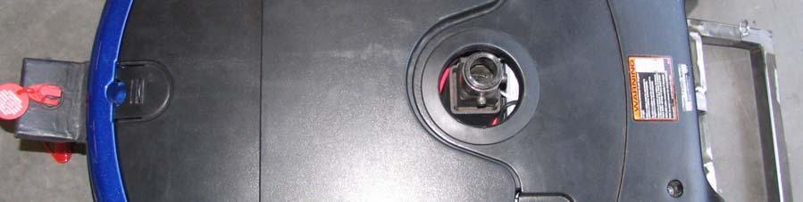
2 KEYED IGNITION The keyed Ignition allows for more control and safety over your wheelchair trainer. With the trainer being inoperable without the key engaged you will be in full control of this system. To operate keyed ignition: 1. Insert key into ignition slot, see on the right 2. Turn 90 degrees to the right until green light indicator turns on, see on the right 3. To turn off, turn 90 degrees to the left until green light indicator turns off. WARNING: Key should not be removed when operating in motion. Key can only be removed in the OFF position


3 EMERGENCY KILL SWITCH The emergency kill switch allows the aid control external control over the trainer. By attaching the cord of the kill switch to the body of the attending aid, they will be able to instantaneously slow down and stop the trainer in the case of an emergency. This device cuts power to the motors when pulled. To operate emergency kill switch: 1. Inserting: To insert kill switch, hold three prong connector with large prong on top and two smaller prongs on bottom. 2. At an angle, push button on trainer down with connector and slide into place. See. 3. Disengaging: To stop trainer in motion, pull on the tether cord until connector unattaches from trainer. See. 4. When disengaged blinking red light near keyed ignition will be visible. See Figure 3. WARNING: Emergency Kill Switch should always be engaged unless in the case of an emergency. Leave attached when not in use, blinking red indicator will tell blink with or with out keyed ignition. Figure 3

 Retractable")
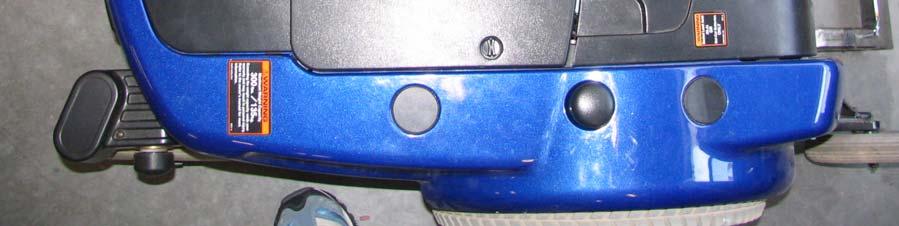
4 Wheelchair Trainer Base Parts Description Roadway U-Bracket Frame base (cross bars) Retractable strap


. 3.")


5 BASE CONNECTION The Jazzy 1122 base and the wheelchair trainer base can be reconnected for operation. Attaching wheelchair base: 1. Turn the power off. 2. Make sure Jazzy 1122 has the power drive engaged (i.e. Not in freewheel mode). 3. Align the wheelchair base mount to the custom mount of the Jazzy1122, see figure Insert cotter pin to connect Jazzy 1122 to wheelchair base, see figure Connect plug into the controller, see figure Wheelchair trainer is ready to operate. Figure 3

.")

6 BASE REMOVAL The wheelchair base may be removed from the Jazzy 1122 base for elevator access. To remove wheelchair base 1. Turn the power off. 2. Make sure Jazzy 1122 has the power drive disengaged (i.e. in freewheel mode). 3. Disconnect powered base from controller joystick, see figure Remove both cotter pins from mount, see figure 2.


7 5. Move wheelchair trainer forward to remove, see figure 3 and The Jazzy 1122 base can now be maneuvered by the controller, see figure 5. Figure 3 Figure 4 Figure 5


 located near the")

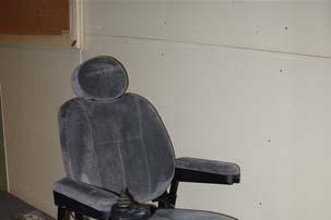
8 SECURE WHEELCHAIR TO WHEELCHAIR BASE For the safety of wheelchair occupant the wheelchair must be fully constrained to the wheelchair base. To secure wheelchair: 1. Turn the power off. 2. Make sure Jazzy 1122 has the power drive engaged (i.e. Not in freewheel mode). 3. Fasten hook and loop fastener strap to right I bar (on the wheelchair) and the right U- bracket (on wheelchair base) located near the front wheels, see figure Repeat step 3, for the left side. 5. Press release button on retractable tie down strap to release hook, figure 3. Figure 3


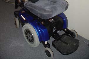
9 6. Hook right retractable tie downs to the frame on the right side of occupant s wheelchair, see figure Manually tighten retractable tie downs, see figure 5. CAUTION: DO NOT OVER TIGHTEN 8. Make sure there is enough tension on strap, see figure Repeat step 5-8, for the left side. Figure Check that chair is completely secure Figure 5 Figure 6


10 11. The chair is now completely secured, figure 7. Figure 7


11 LOAD WHEELCHAIR BASE Load the occupant onto the wheelchair trainer base for operation mode. To load occupant onto base: 1. Turn the power off. 2. Make sure Jazzy 1122 is connected to wheelchair base for easier loading. See section on base connection. 3. Ensure the power drive is engaged on the Jazzy 1122 (i.e. Not in freewheel mode). 4. Align Wheelchair base and occupants wheelchair in a straight line, see figure Put one foot between frame of base and roll wheelchair base along the roadway of the wheelchair trainer, see figure 1. CAUTION: Do not step on frame of wheelchair base. 6. Grasp handle of occupants wheelchair, see figure 2.


12 7. Gently roll occupied wheelchair up onto the base lifting the rear wheels and then the front wheels onto the roadway. Figure 3 Figure 4


.")


13 UNLOADING WHEELCHAIR When unloading the wheelchair from the wheelchair trainer base, safety must be considered. To unload occupant from wheelchair base: 1. Turn the power off. 2. Make sure Jazzy 1122 has the power drive engaged (i.e. Not in freewheel mode). 3. Press release button on retractable tie down to loosen strap, figure Remove hook from wheelchair frame. 5. Repeat steps 3 and 4 for other side of wheelchair base Figure 3


14 6. While holding occupied wheelchair, unfasten hook and loop strap from U-bracket and I bar near the front wheels, see figure Carefully push wheelchair forward using occupant s wheelchair handles slowly until wheelchair is fully rested on floor. Figure 4 Figure 5 Figure 6


15 CONVERT TO JAZZY 1122 The wheelchair trainer base can be converted back to a Jazzy 1122 power wheelchair as needed. To make conversion to a Jazzy: 1. Turn the power off. 2. Open electrical compartment shroud, see figure Remove control harness plug, see figure Remove controller joystick from mount and tread controller cable through controller mount holder, see figure 3. Figure 3


16 5. Remove control mount by a thumb screw at the base of the mount, see figure 4 and Remove wheelchair base as per base removal instructions, see figure 6. Figure 4 Figure 5 Figure 6


17 7. Remove shroud, by removing the two screws located on the top front of the black panel. Lift the shroud, see figure Remove cotter pin connecting the mount to the powered base, see figure Lift wheelchair base mount and remove, see figure 9. Figure 7 Figure 8 Figure 9


18 10. Replace footrest/footrest mount to Jazzy 1122 base, see figure 10 and Replace shroud and two screws. 12. Assemble the controller and seat following the Jazzy 1122 owner s manual, section IV


19 13. Conversion completed, see figure

.")


.")

20 STORE WHEELCHAIR TRAINER BASE When the Wheelchair trainer is not in use the base can be stored easily. To store wheelchair trainer base: 1. Turn the power off. 2. Make sure Jazzy 1122 power drive is disengaged (i.e. in freewheel mode). 3. Make sure the base of the Jazzy 1122 and the wheelchair base are connected securely. See base connection section. 4. Lift front of the wheelchair base and use this as a handle to maneuver the Jazzy 1122 to a proper storage location, see figure 1 and For additional safety, engage the Jazzy 1122 powered drive (i.e. Not in freewheel mode). 6. The wheelchair trainer can now be stored until needed, by leaning the wheelchair base against the Jazzy 1122 base, see figure Secure wheelchair base to control bar using long hook and loop fastener. CAUTION: Do not over tighten strap. Figure 3

21 Installation of the IR Communication Device The IR Communication Device allows use of the IR Devices such a Dynavox. Tools: None. To install the IR Communication Device: WARNING: Installing the Communication Device the whole unit should be OFF. 1. Power OFF from Joystick 2. Place key ignition to the OFF position. 3. Snap the Power connector, see figure Connect the green RC connector to the green label, see figure Connect both red and blue RC jacks to the appropriate color code labels on the Joystick side, see figure 3 and from the Communication Device, see figure 4 on the next page. Figure 3


22 CAUTION: Make sure connectors are tight and colors are match appropriately. 6. Mount the IR Receiver Module to a Communication Device. 7. Turn the key switch to the ON position. 8. Power ON Jazzy 1122, power button located on the Joystick. Figure 4 WARNING: Safely warp louse wires away from user and moving parts. 9. If indicators are free of errors, operate like normal.
23 Removal of the IR Communication Device The IR Communication Device allows use of the IR Devices such a Dynavox. Tools: None. Removal of the IR Communication Device: WARNING: Removing the Communication Device the whole unit should be OFF. 1. Power OFF from Joystick 2. Place key ignition to the OFF position. 3. Squeeze and pull apart the power connector, see figure Disconnect the green RC connector from the green label, see figure Disconnect the red and blue RC connectors from the Joystick; see figure 3, and from the communication device. 6. Place key ignition to the ON position, LED will turn Green. 7. Power ON from Joystick. The IR Communication Device is now disconnected. Figure 3


24 Removal of Batteries Remove the shell cover to disconnect the batteries. See Removal of shell in the manual. Tools: None. To remove the Batteries: 1. Once shell is remove disconnect Anderson connectors, see figure 1 and 2. CAUTION: When removing batteries, watch out for wires and parts. A good snag can damage parts or rip wires out. See figure 3. WARNING: PULL FROM HANDLES ON BATTERY. 2. Remove Batteries straight up, See figure 4. Figure 3

25 Installing Batteries Remove the shell cover install batteries. See Removal of shell in the manual. Tools: None. To install the Batteries: CAUTION: When installing batteries, watch out for wires and parts. A good snag can damage parts or rip wires out. See figure See bottom of main unit to place appropriate Gel battery. Place appropriate Gel Battery straight in, arrows pointing out. WARNING: Tuck away all wire from moving parts. 2. Locate the appropriate color coated Anderson connectors see figure Attach the Anderson connectors by firmly pushing connectors together, see figure Attach shell; see section to install shell in the Wheelchair Trainer manual. Figure 3


26 WARNING Please do not push the base of the Jazzy 1122 by the control bar, see figure 1. The control bar is not a structural member. WARNING Do not step on the cross bars of the wheelchair trainer, see figure 2.


27 TROUBLESHOOTING In the case that your trainer is not operating properly follow these steps to determine the cause of the problem. 1. Circuit breaker: Some operations could potential cause the 50 Amp circuit breaker on the back of the Jazzy chair to become tripped. Push to reset. See 2. Batteries not charging: The Ammeter on the back of the Jazzy chair is used to indicate the rate of charge being applied to the batteries. Check to make sure batteries are being charged See Ammeter on left side of Figure 1 3. Fuses: Your wheelchair trainer is equipped with two fuses. a. The red fuse is used for charging and basic chair operations b. The clear fuse is used for the ignition, communication system, and kill switch. If incorrect operation is occurring change fuse with new identical fuses. See 4. Communication device: If the communication device is not operating, check to make sure that the correct drive control is plugged in. If not plugged in factory joystick will operate.
28 Notes
29 Notes
Lift N Go [Model 210] Electric Carrier For use with power chairs & scooters Installation Guide & Owners Manual
![Lift N Go [Model 210] Electric Carrier For use with power chairs & scooters Installation Guide & Owners Manual](/thumbs/74/70316262.jpg "Lift N Go [Model 210] Electric Carrier For use with power chairs & scooters Installation Guide & Owners Manual") 203 Matzinger Road Toledo, OH 43612 Phone: 1-800-541-3213 Fax: (419) 478-4425 www.wheelchaircarrier.com E-mail: admin@wheelchaircarrier.com Lift N Go [Model 210] Electric Carrier For use with power chairs
203 Matzinger Road Toledo, OH 43612 Phone: 1-800-541-3213 Fax: (419) 478-4425 www.wheelchaircarrier.com E-mail: admin@wheelchaircarrier.com Lift N Go [Model 210] Electric Carrier For use with power chairs
JEEVES. JEEVES Installation Manual. Installation Manual The Easiest Do-It-Yourself Dumbwaiter on the Market
 1 888-323-8755 www.nwlifts.com JEEVES Installation Manual The Easiest Do-It-Yourself Dumbwaiter on the Market This manual will cover the installation procedure step-by-step. The installation of this dumbwaiter
K-SERIES PUBLIC USE LIFT OPERATING INSTRUCTIONS
 -PRINT- II. T K-SERIES PUBLIC USE LIFT OPERATING INSTRUCTIONS -TABLE OF CONTENTS- his chapter contains safety precautions, daily safety check instructions, control and indicator descriptions, and operating
How to remove and replace the Foonf/Fllo fabric
 How to remove and replace the Foonf/Fllo fabric Remove Headrest Locate the Troubleshooting Tool behind the manual on the back of the car seat, as shown in Figure 1. Raise Headrest to highest position by
SERVICE MANUAL. Chairman 2k/2s
 SERVICE MANUAL Chairman 2k/2s US How to contact Permobil Permobil Inc. USA 6961 Eastgate Blvd. Lebanon, TN 37090 USA Phone: 800-736-0925 Fax: 800-231-3256 Email: info@permobilusa.com Head Office of the
S-SERIES PUBLIC USE OPERATING INSTRUCTIONS
 -PRINT- II. T S-SERIES PUBLIC USE OPERATING INSTRUCTIONS -TABLE OF CONTENTS- his chapter contains safety precautions, daily safety check instructions, control and indicator descriptions and operating instructions
Quickie S-11 Service Manual
 Quickie S-11 Service Manual 05 Sunrise Medical Inc. 100740 Rev A Quickie S-11 Troubleshooting Guide INTRODUCTION... 0.1 Specifications VSI Controller... 0.2 Plugs/Connectors... 0.3 Main Wiring Diagram/
SERVICE MANUAL. Chairman
 SERVICE MANUAL Chairman US How to contact Permobil Permobil Inc. USA 6961 Eastgate Blvd. Lebanon, TN 37090 USA Phone: 800-736-0925 Fax: 800-231-3256 Email: info@permobilusa.com Head Office of the Permobil
ALTERNATOR PRECAUTIONS. Some precautions should be taken when working on this, or any other, AC charging system.
 The alternator charging system is a negative (-) ground system which consists of an alternator, a regulator, a charge indicator, a storage battery and wiring connecting the components, and fuse link wire.
US208S Scooter Carrier - US208P Power Chair Carrier 210 Lift N Go 130 Swing Away Installation Guide & Owners Manual
 7325 Douglas Rd. Lambertville, MI 48144 Phone: 1-800-541-3213 Fax: (734) 568-6705 www.wheelchaircarrier.com E-mail: admin@wheelchaircarrier.com US208S Scooter Carrier - US208P Power Chair Carrier 210 Lift
US208S Scooter / Power Chair Carrier Lift N Go 117 Mini Electric Lift Electric Tote & 130 Swing Away Installation Guide & Owners Manual
 7325 Douglas Rd. Lambertville, MI 48144 Phone: 1-800-541-3213 Fax: (734) 568-6705 www.wheelchaircarrier.com E-mail: admin@wheelchaircarrier.com US208S Scooter / Power Chair Carrier - 210 Lift N Go 117
Troubleshooting Flowcharts
 Hydraulic Leveling System Troubleshooting Flowcharts Table of Contents Page PowerLevel Already Level 2 Panel Communication 2 Park Brake 3 Emergency Retract 4 Zero Mode 5 Out of Level Tolerance 5 Wait 6
HD 7700 Setup & Operator Manual
 HD 7700 Setup & Operator Manual Issue 1 December, 01 Performance Design Inc. The Heavy Duty Ultima (HD 7700) electric punch has been designed to punch most any job that may pass through your bindery or
Quick Install Lift AL065 Installation Guide & Owners Manual
 Quick Install Lift AL065 Installation Guide & Owners Manual Congratulations on your new lift purchase. The Quick Install Lift line is one of the easiest and most trouble free ways to transport your scooter
S-SERIES ADA TRANSIT USE OPERATING INSTRUCTIONS
 -PRINT- II. T S-SERIES ADA TRANSIT USE OPERATING INSTRUCTIONS -TABLE OF CONTENTS- his chapter contains safety precautions, daily safety check instructions, control and indicator descriptions, and operating
CAUTION -TABLE OF CONTENTS- II. OPERATING INSTRUCTIONS
 -PRINT- -TABLE OF CONTENTS- II. OPERATING INSTRUCTIONS his chapter contains safety precautions, daily safety check instructions, control and indicator descriptions, and operating instructions that apply
PRODUCT INFORMATION BULLETIN #3365 DIGITAL MOTOR CONTROL PLATTER SYSTEMS For Serial Number and After
 PRODUCT INFORMATION BULLETIN #3365 DIGITAL MOTOR CONTROL PLATTER SYSTEMS For Serial Number 28640996 and After Record Platter System Identification Numbers Here: Model # Serial # Table of Contents Program
INSTALLATION INSTRUCTIONS DODGE DAKOTA 2 KIT # 682 (2WD), 692 (4WD) 3 KIT # 683 (2WD), 693 (4WD)
, 692 (4WD) 3 KIT # 683 (2WD), 693 (4WD)") INSTALLATION INSTRUCTIONS 1997-1999 DODGE DAKOTA 2 KIT # 682 (2WD), 692 (4WD) 3 KIT # 683 (2WD), 693 (4WD) Installation of a Performance Accessories body lift kit will change the vehicle s center of gravity
INSTALLATION INSTRUCTIONS 1997-1999 DODGE DAKOTA 2 KIT # 682 (2WD), 692 (4WD) 3 KIT # 683 (2WD), 693 (4WD) Installation of a Performance Accessories body lift kit will change the vehicle s center of gravity
SEAT BELTS SECTION CONTENTS H RESTRAINTS SB-1
 H RESTRAINTS A SECTION SEAT BELTS B C D CONTENTS E PRECAUTIONS... 2 Precautions for Supplemental Restraint System (SRS) AIR BAG and SEAT BELT PRE-TEN- SIONER... 2 Precaution for Seat Belt Service... 2
Troubleshooting Flowcharts
 Hydraulic Leveling System Troubleshooting Flowcharts #82-L0507 9/08 Power Gear/Kwikee Rev. 0B Table of Contents Page PowerLevel Already Level 2 Panel Communication 2 Park Brake 3 Emergency Retract 4 Zero
SEAT BELTS SECTION CONTENTS H RESTRAINTS SB-1
 H RESTRAINTS A SECTION SEAT BELTS B C D CONTENTS E PRECAUTIONS... 2 Precautions for Supplemental Restraint System (SRS) AIR BAG and SEAT BELT PRE-TEN- SIONER... 2 Precaution for Seat Belt Service... 2
READ AND FOLLOW ALL SAFETY INSTRUCTIONS SAVE THESE INSTRUCTIONS
 7.5 Swift Lock Ready Shape Tree (Patent Pending) Instructions IMPORTANT SAFETY INSTRUCTIONS When using electrical products, basic precautions should always be followed including the following: READ AND
CORPORATION OPERATOR S MANUAL HWH HYDRAULIC SPACEMAKER ROOM EXTENSION SYSTEMS. FEATURING: Single / Multiple Room Extensions / Generator Slide
 HWH CORPORATION R OPERATOR S MANUAL HWH HYDRAULIC SPACEMAKER R ROOM EXTENSION SYSTEMS R FEATURING: Single / Multiple Room Extensions / Generator Slide H W H CORPORATION R HYDRAULIC ROOM EXTENSION OFF EXTEND
Convertible top OPENING THE CONVERTIBLE TOP CAUTIONS
 Convertible top OPENING THE CONVERTIBLE TOP WARNINGS Before opening or closing the convertible top, ensure that all occupants have moved their hands, fingers, hair, etc. clear of moving parts. Do not place
Generator, removing and
 Page 1 of 14 27-26 Generator, removing and installing CAUTION! Disconnect the battery Ground (GND) strap before working on the electrical system. Notes: Before disconnecting the battery, determine the
Coil Inserter Module
 Coil Inserter Module 1) Installation Instructions: Diagram 4 Procedure to attach the coil inserter onto the OD 4012 punch Unplug the main power cord from the OD 4012. Remove the two safety screws (3/32
Product Name Chair Conversion Kit (to LR Delivery Unit) Installation [Kit # xx]
![Product Name Chair Conversion Kit (to LR Delivery Unit) Installation [Kit # xx]](/thumbs/75/71790484.jpg "Product Name Chair Conversion Kit (to LR Delivery Unit) Installation [Kit # xx]") Elevance Product Name Chair Conversion Kit (to LR Delivery Unit) Installation Installation [Kit #002-1966-xx] Attention: Use this kit to convert an Elevance Chair to a Chair with an Elevance LR mounted
Elevance Product Name Chair Conversion Kit (to LR Delivery Unit) Installation Installation [Kit #002-1966-xx] Attention: Use this kit to convert an Elevance Chair to a Chair with an Elevance LR mounted
I. Before starting installation
 5. Park the vehicle on a clean, dry, flat, level surface and block the tires so the vehicle cannot roll in either direction. A. Disconnect battery cables 1. Disconnect the negative cable first, then the
CI 3000 Coil Inserter
 CI 3000 Coil Inserter Setup & Operator Manual Issue 1 April 02 Performance Design Inc. The CI 3000 plastic spiral inserter will bind books up to 1-1/8 (28.6mm) thick using coil diameters from 3/16 (5mm)
SERVICE MANUAL. Chairman HD3
 SERVICE MANUAL Chairman HD3 US How to contact Permobil Head Office of the Permobil group Produced and published by Permobil AB, Sweden Edition no.3, 2009-08 Article no.: 201161-US-0 Contents Contents
CONVERSION FROM MANUAL PULL STRAP TO POWER AWNING
 White Kit # Black Kit # Description 323948 323949 Conversion from Manual Pull Strap to Power Awning Kit Note: Parts below are available in kits referenced above or individually as needed. White Part #
HP BladeSystem c7000 Carrier-Grade Options Installation Guide
 HP BladeSystem c7000 Carrier-Grade Options Installation Guide Part Number 5991-8062 September 2009 (Second Edition) Copyright 2009 Hewlett-Packard Development Company, L.P. The information contained herein
Instrument Panel Assembly Replacement. Fig. 14 Battery Negative Cable Removal/Installation
 Page 1 of 11 Home Account Contact ALLDATA Log Out Help BILL SEIDLES MITSUBISHI Select Vehicle New TSBs Technician's Reference Component Search: OK 2003 Chrysler Truck PT Cruiser L4-2.4L VIN B Conversion
w w w. h d o n l i n e s h o p. d e CRUISE CONTROL KIT GENERAL INSTALLATION -J04064 REV Kit Number Models Additional Parts Required
 -J006 REV. 006-08- CRUISE CONTROL KIT GENERAL Kit Number 7796-07 Models For the most up-to-date model fitment information, please see the product label or www.harley-davidson.com. Additional Parts Required.
Supertop Replacement Top with Tinted Side and Rear Windows Installation Instructions
 Supertop Replacement Top with Tinted Side and Rear Windows Installation Instructions TM Inc. For: Wrangler TJ 1997 2002 Part Number: 55629 Does Not Include Hardware This product is only designed for the
LIPPERTCOMPONENTS, INC.
 LIPPERTCOMPONENTS, INC. SCHWINTEK INWALL SLIDEOUT SYSTEM OPERATION AND SERVICE MANUAL Contents I. Controls 1-1 System components 1 1-1A versions C1 & C2 2 1-2 Motor wiring harness connections 3 1-3 Extend
G3 UHT TRANSMISSION. G3 UHT Transmission Replacement. G3 UHT Transmission Removal
 G3 UHT Transmission Replacement The following procedures cover replacing the left hand UHT Transmission. The same procedures can be followed to remove the right hand UHT Transmission. 5. Raise the seat
MAINTENANCE WEIGHT RATINGS WARNINGS. warning: never exceed your vehicle manufacturer's recommended towing capacity
 Installation instructions warning: never exceed your vehicle manufacturer's recommended towing capacity Round Bar WEIGHT DISTRIBUTION kit MAINTENANCE Keep the socket-mounted ends of the spring bars and
INSTALLATION INSTRUCTIONS
 INSTALLATION INSTRUCTIONS Model: 8510 & 8510TK Ford E Series Van 1994 2002 with stock power mirrors Tools required for the installation are: 7/16 socket, T20 screwdriver or 8mm socket, screwdriver, phillips
Table of Contents. Timer Identification Timer ID BLU-U Features: 1K 6K BLU-U Features 1K 6K
 DUSA Pharmaceuticals, Inc. Table of Contents Go to Chart # Timer Identification Timer ID BLU-U Features: 1K 6K BLU-U Features 1K 6K BLU-U Features: 10K BLU-U Features 10K BLU-U Symptom Fans Running, Timer
For: Model Year Jeep Wrangler/TJ Part Number: For: Model Year Jeep Wrangler/TJ Part Number: 58709
 TJ Tinted Window Kit Installation Instructions TM For: 1997-2002 Model Year Jeep Wrangler/TJ Part Number: 58609 For: 2003-2004 Model Year Jeep Wrangler/TJ Part Number: 58709 www.bestop.com Inc. DO NOT
Electric motor testing
 Electric motor testing MOTOR (MODELS EJ4-4001 AND EJ8-4001A) 23 GENERAL INFORMATION The vehicle is equipped with a 48-volt DC, shunt-wound, reversible traction motor. The shunt-wound motor is designed
1999 Volkswagen New Beetle GL
 Driver side airbag unit, removing and installing Removing CAUTION: Never let anyone sit in the passenger compartment when the airbag system is being worked on, especially when the airbag system is being
AQUOS LE810/820 QUATTRON LED REPLACEMENT LC-60LE810/820
 AQUOS LE810/820 QUATTRON LED REPLACEMENT LC-60LE810/820 Ver. FF Kit LEDKIT60LE8x Part number: LEDKIT60LE8x AQUOS LE810/820 QUATTRON LED REPLACEMENT LEDKIT60LE8X (1) Wiring Harness (1) Side LED Strip (2)Top
Changing the Struts on a WK Jeep CRD
 Changing the Struts on a WK Jeep CRD Step by Step By Chirpz Disclaimer: I do not claim that this procedure is the right way or even the best way to change your struts. This is what I did after reading
FOG LAMPS INSTALL KIT
 FOG LAMPS INSTALL KIT PT CRUISER INSTALLATION INSTRUCTIONS Read entire instructions thoroughly before starting. For proper aiming of fog lamps, follow procedures in the service manual. NOTES: Left and
SERVICE MANUAL. Koala
 SERVICE MANUAL Koala US How to contact Permobil Permobil Inc. USA 6961 Eastgate Blvd. Lebanon, TN 37090 USA Phone: 800-736-0925 Fax: 800-231-3256 Email: info@permobilusa.com Head Office of the Permobil
TABLE OF CONTENTS I. SERVICE & MAINTENANCE PROCEDURES. 1) Opening and closing of door latch. 2) Latch assembly and adjustment
 Opening and closing of door latch. 2) Latch assembly and adjustment") TABLE OF CONTENTS I. SERVICE & MAINTENANCE PROCEDURES 1) Opening and closing of door latch 2) Latch assembly and adjustment 3) Latch cover removal and replacement 4) Upper slider track adjustment 5) Lower
TABLE OF CONTENTS I. SERVICE & MAINTENANCE PROCEDURES 1) Opening and closing of door latch 2) Latch assembly and adjustment 3) Latch cover removal and replacement 4) Upper slider track adjustment 5) Lower
SERVICE MANUAL. Chairman. Playman/Robo
 SERVICE MANUAL Chairman Playman/Robo US How to contact Permobil Permobil Inc. USA 6961 Eastgate Blvd. Lebanon, TN 37090 USA Phone: 800-736-0925 Fax: 800-231-3256 Email: info@permobilusa.com Head Office
Installation, Usage & Maintenance Guide
 3-Point Seat Belt Installation, Usage & Maintenance Guide For Fixed, Suspension & Bench Seats This guide should remain with the vehicle and passed on to subsequent vehicle owners to be kept for future
The Safe Operation of Golf Carts, Accessibility Carts and Low-Speed Vehicles On Campus. USC Upstate Department of Public Safety
 The Safe Operation of Golf Carts, Accessibility Carts and Low-Speed Vehicles On Campus USC Upstate Department of Public Safety Types of Utility Vehicles Golf Carts Low Speed Vehicles Accessibility Vehicles
Front Bumper Fascia Replacement
 Page 1 of 10 2008 Pontiac G8 G8 Service Manual Body Repair Bumpers and Fascias Repair Instructions Document ID: 2044380 Front Bumper Fascia Replacement Removal Procedure Caution: Refer to Safety Glasses
Marlon Xplore SxS Deck Owner s Manual Assembly & Installation Instructions
 Marlon Xplore SxS Deck Owner s Manual Assembly & Installation Instructions 2850lbs load max on deck 2500lbs load max on ramps Marlon Recreational Products www.marlonproducts.com 1-800-663-7367 IMPORTANT
Product Name Chair Conversion Kit (to Console Delivery Unit) Installation [Kit # xx]
![Product Name Chair Conversion Kit (to Console Delivery Unit) Installation [Kit # xx]](/thumbs/85/92245042.jpg "Product Name Chair Conversion Kit (to Console Delivery Unit) Installation [Kit # xx]") Elevance Product Name Chair Conversion Kit (to Console Delivery Installation Unit) Installation [Kit #002-1965-xx] Attention: Use this kit to convert an Elevance Chair to a Chair with an Elevance Console
Elevance Product Name Chair Conversion Kit (to Console Delivery Installation Unit) Installation [Kit #002-1965-xx] Attention: Use this kit to convert an Elevance Chair to a Chair with an Elevance Console
Quick Start Guide Compact 22 LE ( s/n & up)
") Quick Start Guide Compact 22 LE (920013 s/n 75000 & up) Step 1: Assemble Handlebar Step 2: Install Discharge Chute Step 3: Install Discharge Chute Crank Step 4: Check Function of Dual Handle Interlock
Quick Start Guide Compact 22 LE (920013 s/n 75000 & up) Step 1: Assemble Handlebar Step 2: Install Discharge Chute Step 3: Install Discharge Chute Crank Step 4: Check Function of Dual Handle Interlock
INSTRUCTION BULLETIN
 INSTRUCTION BULLETIN No. 328288 Machine: M20/T20/M30/ S30 Published: 05-2011 Rev. 00 NOTE: DO NOT DISCARD the Parts List from the Instruction Bulletin. Place the Parts List in the appropriate place in
THE GLIDER 5th Wheel Attachment
 April 2007 APPLICATION: INSTALLATION INSTRUCTIONS MODEL NO. 70460 70046 THE GLIDER 5th Wheel Attachment For use on short bed pickup applications US Patent No. 6247720 COMPLETE PARTS LIST Part Description
Installation Instructions for Foam Marker ZMAX
 2017 Installation Instructions for Foam Marker ZMAX We appreciate your purchase of L.T. Rich s Product. Please Verify Contents before beginning installation. JLD;AES L.T.RICH 5/2/2017 SHIPPING CONTENTS...
JUNCTION BLOCK DESCRIPTION OPERATION XK 8W-97 POWER DISTRIBUTION 8W
 XK 8W-97 POWER DISTRIBUTION 8W - 97-7 JUNCTION BLOCK DESCRIPTION An electrical Junction Block(JB) is concealed beneath the driver side of the instrument panel in the passenger compartment of the vehicle.
INSTRUCTION MANUAL 16K - Fifth Wheel Hitch
 You can take it with you. INSTRUCTION MANUAL 16K - Fifth Wheel Hitch Product No. 30047 DEALER/INSTALLER: END USER: (1) Provide this Manual to end user. (2) Physically demonstrate hitching and unhitching
Switch and Fuse Installation... 1 Awning LED Layouts... 2 Small Box and Marquee LED Layouts... 2 Big Box LED Layouts... 3
 SERVICE MANUAL BOX AWNING LED RV SPECIFICATIONS MOUNTING: LED light strip is factory mounted in specially designed groove in the lead rail. LENGTH: POWER: CONTROLS: TABLE OF CONTENTS Available for awnings
Futura 20/60. Car Seat OWNER S MANUAL. Models 79013, 79014
 Futura 20/60 Car Seat OWNER S MANUAL Models 79013, 79014 Message to Parents Thank you for choosing the Fisher-Price Futura 20/60 Car Seat. Before you use this car seat, please take time to read and understand
It don t mean a thing If it ain t got the swing
 SWING CHUTE SAND/SALT SPREADER INSTALLATION AND OPERATING INSTRUCTIONS SWING CHUTE SPREADER MODELS: 7, 8, 9, 9.5 & 10 MANUAL FOR SPREADER SERIAL NUMBERS AFTER # 20000 It don t mean a thing If it ain t
Competitor. Ultra Light Plus, Semi Electric Bed. Item # Owner s Assembly And Operating Manual
 Competitor Ultra Light Plus, Semi Electric Bed Item # 15560 Owner s Assembly And Operating Manual 1 2 Assembly Instructions 1. Remove contents from carton. 2. Place both ends of the sleep surface on their
SUBJECT: While In Bi-level Mode, Air Flow From Panel Vents Is Less Than That Of The Floor Vents
 NUMBER: GROUP: 24-20-99 Rev. A Heating & A/C DATE: Dec. 17, 1999 This bulletin is supplied as technical information only and is not an authorization for repair. No part of this publication may be reproduced,
MAGELLAN. Convertible Car Seat
 MAGELLAN Convertible Car Seat 4358-7373B 5.7.18 KEEP INSTRUCTIONS FOR FUTURE USE. Read all instructions before using this car seat. WARNING: Failure to follow the warnings on the labels and in the instruction
DESCRIPTION & OPERATION
 SEATS - POWER 1998 ACCESSORIES & EQUIPMENT General Motors Corp. - Power Seats DESCRIPTION & OPERATION Power seats operate using toggle switches located on seat side. Seat adjusters are powered by a 12-volt,
2-row and All-row systems included.
 Ag Leader Technology Cotton Picker Installation Installation Instructions for John Deere cotton picker models: 2-row and All-row systems included. IMPORTANT: Ensure the model numbers shown above correspond
DESIGNED BY EXPERIENCE PLASTIC SPHERE DISPENSER USER MANUAL. Manufactured by PSDS, Inc. for sole distribution by:
 DESIGNED BY EXPERIENCE PLASTIC SPHERE DISPENSER USER MANUAL Manufactured by PSDS, Inc. for sole distribution by: AEROSTAT, INC. 8830 AIRPORT BLVD LEESBURG, FL 34788 WEBSITE: AEROSTATINC.COM TEL: 352 787-1348
AL625 & AL625HD INSTALLATION & OWNER S MANUAL
 AL625 & AL625HD INSTALLATION & OWNER S MANUAL These instructions are provided to assist you in the installation of the AL625. If you require further assistance, our trained staff is ready to provide you
INSTALLATION INSTRUCTIONS
 INSTALLATION INSTRUCTIONS WARNING: NEVER EXCEED YOUR VEHICLE MANUFACTURER'S RECOMMENDED TOWING CAPACITY PIN-STYLE TRUNNION BAR WEIGHT DISTRIBUTION KIT MAINTENANCE Keep the socket-mounted ends of the spring
The steering column is only available as a complete unit, without steering lock housing, as a replacement part.
 Page 1 of 17 Volkswagen > New Beetle > 1998-2005 Suspension, wheels, steering 48 - Steering column Steering column, removing and installing Special tools, testers and auxiliary items required Torque wrench
Detroit Speed, Inc. Electric Headlight Door Kit Corvette P/N: &
 Detroit Speed, Inc. Electric Headlight Door Kit 1968-82 Corvette P/N: 122006 & 122007 The Detroit Speed Inc. Electric Headlight Door Kit replaces the stock vacuum actuated system on all 1968-82 Corvettes.
INSTALLATION INSTRUCTIONS
 INSTALLATION INSTRUCTIONS REAR DISC BRAKE CONVERSION KIT A126-3 1988-98 CHEVY K1500 4WD 10" DRUMS Thank you for choosing STAINLESS STEEL BRAKES CORPORATION for your braking needs. Pleases take the time
CONVERTIBLE CAR SEAT ISOFIX COMPATIBLE Birth to 4 years (approx)
") CONVERTIBLE CAR SEAT ISOFIX COMPATIBLE Birth to 4 years (approx) REARWARD FACING Birth to 2-3 years (approx) Series No. BS7200A-i20133 FORWARD FACING 12 months to 4 years (approx) IMPORTANT: KEEP THIS
CONVERTIBLE CAR SEAT ISOFIX COMPATIBLE Birth to 4 years (approx) REARWARD FACING Birth to 2-3 years (approx) Series No. BS7200A-i20133 FORWARD FACING 12 months to 4 years (approx) IMPORTANT: KEEP THIS
OLYMPIAN MODEL 740 Operation and Service Manual
 OLYMPIAN MODEL 740 Operation and Service Manual P/N 133911-102 FCI MANUAL P/N 133865-001 Data herein has been verified and validated and believed adequate for the intended use. If the machine or procedures
Quickie Rhapsody Service Manual
 Quickie Rhapsody Service Manual 2006 Sunrise Medical Inc. 101976 Rev A Quickie Rhapsody Service Manual Contents Introduction... 0.1 VR2 Controller... 0.2 Plugs/Connectors... 0.3 Basic Tool List & Main
BMW 745Li E65/E66 Rear Brake Pad Replacement By Jerry Incollingo (Jerry 745Li)
") Page 1 of 11 BMW 745Li E65/E66 Rear Brake Pad Replacement By Jerry Incollingo (Jerry 745Li) This guide will detail how to change the rear brakes on late model BMW E65 / E66 s. It was performed on a 2003
Page 1 of 11 BMW 745Li E65/E66 Rear Brake Pad Replacement By Jerry Incollingo (Jerry 745Li) This guide will detail how to change the rear brakes on late model BMW E65 / E66 s. It was performed on a 2003
RoadRelay 4. Installation Guide
 RoadRelay 4 Installation Guide RoadRelay 4 Installation Guide Bulletin No. 3401767 Revision B Copyright 2002, Cummins Inc. All rights reserved. Cummins Inc. shall not be liable for technical or editorial
Apollo Tilt Wheelchair 18" and 20" Instruction Manual
 Apollo Tilt Wheelchair 18" and 20" Instruction Manual Table of Contents Contents Table of Contents... 2 Introduction... 3 Warning... 4 Safety Guidelines... 5 Parts of the Tilt Wheelchair... 6 Setup & Operation...
TC1000 Service Manual SALES: CUSTOMER SERVICE:
 TC1000 Service Manual SALES: 800-278-3933 CUSTOMER SERVICE: 800-745-1373 Table of Contents Section Page I. Overview 2 II. Troubleshooting Tables 3 III. Maintenance Procedures Procedure 1 Removal and Reinstallation
DODGE DAKOTA 3 BODY LIFT INSTALLATION INSTRUCTIONS KIT # 60153
 DODGE DAKOTA 3 BODY LIFT INSTALLATION INSTRUCTIONS 2003-04 KIT # 60153 Installation of a Performance Automotive Group body lift kit will change the vehicle s center of gravity and handling characteristics
Installation Instructions for Foam Marker INTERMEDIATE also applies: JR, JR36
 2017 Installation Instructions for Foam Marker INTERMEDIATE also applies: JR, JR36 We appreciate your purchase of L.T. Rich s Product. Please Verify Contents before beginning installation. JLD;AES L.T.RICH
Installation and Service Manual
 RAVE Star Lift Installation and Service Manual WARNING! STRICT ADHERENCE TO THESE INSTALLATION INSTRUCTIONS is required and will promote the safety of those installing this product, as well as those who
8W-97 POWER DISTRIBUTION - SERVICE INFORMATION
 HB 8W-97 POWER DISTRIBUTION - SERVICE INFORMATION 8W - 97-1 8W-97 POWER DISTRIBUTION - SERVICE INFORMATION TABLE OF CONTENTS page POWER DISTRIBUTION - SERVICE INFORMATION...1...1 SPECIAL TOOLS POWER DISTRIBUTION
Up-Armored HMMWV CASEVAC Conversion Kit (UAH-CCK)
") M1114 Up-Armored HMMWV CASEVAC Conversion Kit (UAH-CCK) Operation Performance Measures Place CCK Into Operation Task: Conditions & Standard (1) Given one UAH with CCK installed and stored. (2) Two trained
M1114 Up-Armored HMMWV CASEVAC Conversion Kit (UAH-CCK) Operation Performance Measures Place CCK Into Operation Task: Conditions & Standard (1) Given one UAH with CCK installed and stored. (2) Two trained
NAUTILUS SNUGLOCK TM LX/DLX
 NAUTILUS SNUGLOCK TM LX/DLX CHILD RESTRAINT/BOOSTER SEAT Do not install or use this child restraint until you read and understand the instructions in this manual. FAILURE TO PROPERLY USE THIS CHILD RESTRAINT
INSTALLATION INSTRUCTIONS
 INSTALLATION INSTRUCTIONS Models: 7105 & 7105TK Dodge Ram 1500 ('02 Current) Ram 2500 & 3500 '03 - Current with stock manual mirrors. IF YOU DO NOT CURRENTLY HAVE MANUAL MIRRORS, THE WRONG SET HAS BEEN
Competitor. Ultra Light Plus, Semi Electric Bed. Item # 15560, HR Owner s Assembly And Operating Manual
 Competitor Ultra Light Plus, Semi Electric Bed Item # 15560, 15560-HR Owner s Assembly And Operating Manual Note: The competitor bed is available with half-rails (not shown). See page 16 for installation
Convertible Top ! WARNING: OPENING THE CONVERTIBLE TOP
 Convertible Top OPENING THE CONVERTIBLE TOP JAG062L The power-operated convertible top and rear quarter windows, see page 85, are controlled by the switch located on the overhead console. The top latches
Section 7 - Troubleshooting Guide
 Section 7 - Troubleshooting Guide Section 7 - Troubleshooting Guide IMPORTANT While this troubleshooting guide provides information to aid in troubleshooting problems with the range, it does not contain
Troubleshooting Title of Bulletin guide for single phase GFCIs Manual machines
 Bulletin Number: TB084 Type of Bulletin: Informational Products Affected: Manual TracStars: 250/28, 412/618, 500 series II and III. Rolling 412/618 Date of Notification: October 22, 2012 Reason for Bulletin
Owner s Manual. (Keep in glove compartment for quick reference) Rollx Vans Power Door Vans v1.3
 Rollx Vans Power Door Vans v1.3") Owner s Manual (Keep in glove compartment for quick reference) Rollx Vans Power Door Vans v1.3 Table Of Contents Warranty Procedures.................. 4 Warranty Coverage.................... 5 Preventative
Owner s Manual (Keep in glove compartment for quick reference) Rollx Vans Power Door Vans v1.3 Table Of Contents Warranty Procedures.................. 4 Warranty Coverage.................... 5 Preventative
TUFF TORQ TRANSAXLE. Tuff Torq Hydrostatic Transaxle. Transaxle Removal Tuff Torq
 Tuff Torq Hydrostatic Transaxle Internal Service 3. Disconnect the cotter pin and the washer to the brake rod (Figure 63). Internal service information is contained in the Tuff Torq KGIA Transaxle Service
POWER DISTRIBUTION SYSTEMS
 DN POWER DISTRIBUTION SYSTEMS 8O - 1 POWER DISTRIBUTION SYSTEMS TABLE OF CONTENTS page AND POWER DISTRIBUTION SYSTEM....1 POWER DISTRIBUTION CENTER...1 GENERATOR CARTRIDGE FUSE....2 JUNCTION BLOCK...2
Hollywood Racks Assembly & installation instructions for models:
 Hollywood Racks Assembly & installation instructions for models: HR1400Y (4 bike), HR1450Y (2 bike), HR1475Y, 1450Y-E & 1455Y-E (E bikes) For use on 2 hitches only. Do not use a 1 ¼ -2 hitch adapter. Maximum
Installation & Programming Manual. Quick Reference
 Installation & Programming Manual Getting Started Prepare door, per additional instructions (included) before installing unit. IMPORTANT: Read instructions completely before beginning installation. Refer
INSTALLATION INSTRUCTIONS
 INSTALLATION INSTRUCTIONS Document# 19-0038 2004+ Lotus Elise (Series 2) Rear Clamshell Removal Kit Safely support the vehicle. This is a two-person job. Allow 1 to 2 hours for initial disassembly. Have
Model Ci. Intelligent Personal EV P 1 P 3 P 4 P 5 P 6 P 7. Assembly. Basic Insructions. iphone App. Freewheel Mode. Charging.
 Model Ci Intelligent Personal EV Assembly Basic Insructions iphone App Freewheel Mode P 1 P 3 P 4 P 4 Charging P 5 Disassembly Troubleshooting P 6 P 7 1. Assembly This product comes shipped with the five
MODEL CS-41. instructions IMPORTANT: KEEP THIS INSTRUCTION BOOKLET IN THE PLACE PROVIDED ON THE CHILD RESTRAINT
 MODEL CS-41 instructions IMPORTANT: KEEP THIS INSTRUCTION BOOKLET IN THE PLACE PROVIDED ON THE CHILD RESTRAINT Smart Design Please keep this Instruction Booklet in the storage area under the seat for future