Cable Accessories up to 170 kv 4. Experience, Certificates, References. Terminations. Connection Boxes. Installation & Tools
|
|
|
- Marian Allen
- 5 years ago
- Views:
Transcription
1 Content General 3 Cable Accessories up to 170 kv 4 Experience, Certificates, References Terminations Joints Connection Boxes Installation & Tools Equipment for Substations up to 800 kv 46 Surge Arrester High Voltage Connection System (HVCS) Equipment for Transmission up to 500 kv 80 Tension Insulators Hardware for Transmission Lines Hardware for Distribution Lines
2


3 General Energy Division The Energy Division is a part of Tyco Electronics. The headquarter of the Energy Division is based in Ottobrunn, near Munich in Germany. The worldwide activities in of the Energy Division will be handled from here. Besides modern laboratories for Research and Development the production of heat shrink tubings is placed here also the logistic centre for shipments into the whole world. In other countries like United Kingdom and France we have factories for producing the products which will be shown in this catalogue. Germany France United Kingdom Quality and Environment Quality The Tyco Electronics factories are certified to ISO Our vendor routine tests and internal incoming inspection confirm performance of all critical components used in the assembly of our products. We offer competitive lead times on all standard products. Environment The Tyco Electronics factories are also certified to ISO The gentle exposure with natural resources for our products and processes is for us one of the important aspects. Packaging We try to minimize the packaging materials, without any danger for the products. All packaging materials can be disposed without any problems. Recycling The most waste of the different locations will be recycled. If possible this will be done at the location or the waste will be repatriate to the economic cycle in another kind. Production Processes Our production processes are arranged to minimize the influence of the environment. Hereby is the focus on an optimal Energy usage one of the main aspects. With special procedures we use the dispensed warmness from the production machinery to heat the production halls. Water We could reduce the usage of water by concurrent rising of the production volume. Waste We could reduce the amount of waste by concurrent rising of the production volume. Test Procedure and Qualification Tyco Electronics products are tested and certified to the major national and international standards, e. g. IEC, CENELEC, VDE, GOST, BS, etc.

4 Cable Accessories
5 Cable Accessories Experience, Certificates, References 6 Terminations 8 Joints 24 Connection Boxes 32 Installation & Tools 38 5
6 Experience Tyco Electronics Raychem GmbH is one of the World leaders on cable accessories production for voltages up to 170 kv. Our company is focused on development, manufacturing of cable accessories and execution of projects providing reliable operation of electric power systems. Application of Tyco Electronics Raychem GmbH cable accessories provides the increase of customers profitability and competitive capacity due to high operational performance of our products. World s leading enterprises apply our cable accessories which are developed for the long-term operation in most severe conditions of indoor and outdoor maintenance in any climatic zones and high pollution locations. Our products have a very high reliability index which guarantees saving of customers capital outlays. We use an experience accumulated within more than 40 years in sphere of materials science, development of new technologies and intensive study of customers needs. We propose comprehensive approach from supply of our products to putting into operation with single warranty. We constantly improve production technology and quality of our products paying attention to customers increasing requests. Our products passed all relevant tests in independent test labs in order to comply with quality requests of International Standards like IEC, IEEE. Tyco Electronics Raychem GmbH offers a wide range of cable accessories. In this catalogue we present the range from 42 kv up to 170 kv: Outdoor / Indoor Terminations Switchgear terminations and transformer terminations with Corona Shield Joints for plastic insulated cables Inline or shield-break type joints Tyco Electronics Raychem GmbH has technical support centers where customers can get professional assistance. Our specialists are always ready to find solutions for any specific issues of every enterprise. Certificates ISO 9000 series and ISO certifications for almost all locations underline our continuing commitment to quality and the environment. The products are subjected to extensive testing from the time they enter our plants as raw material until they leave as finished products. Requalification testing is carried out on a regular basis with installed components. Customers can thus have full confidence in the products, services and data supplied. In many cases, this saves cost and inconvenience of any further downstream verification.


7 References Our company has realized thousands of projects all over the World including tropical zones, deserts, places behind polar circle and in high pollution industrial and coastal areas. List of countries where our company executed projects with HV cable accessories increases every month and some of them are listed below: Australia Austria Belgium Brazil Canada China Colombia Croatia Denmark Egypt Finland France Germany Greece Hong-Kong India Indonesia Iran Ireland Kenya Korea Lithuania Luxemburg Netherlands Norway Peru Philippines Portugal Russia Saudi Arabia Singapore Slovenia Spain Sweden Taiwan Thailand Ukraine United Arabic Emirates United Kingdom USA Detailed list of projects quantity in each country and names of customers can be presented upon additional inquiry. 7
8 Terminations 8
9 Terminations from 42 kv up to 72 kv General 10 Indoor Terminations 11 Outdoor Terminations 11 Terminations with long creepage 11 Lugs for Terminations 12 Terminations up to 170 kv Outdoor, Composite, Dry plug-in 14 Outdoor, Composite, Oil-filled 16 Connectors for Outdoor Terminations 18 Switchgear & Transformer, Dry plug-in 20 Switchgear & Transformer, Oil-filled 22

10 Termination Systems for Polymeric Insulated Cables up to 72 kv Application Raychem s terminations up to 72 kv are suitable for all climates and environments, even severely polluted areas, and for all installation conditions, including top feed installation. The factory-engineered kits contain a proven termination system which saves space, facilitates installation and enhances system reliability. The special design of the termination, which incorporates pre-coated tracking resistant sealants that melt during the shrinking process, results in a reliable and lasting barrier against moisture and corrosion. Features The slim, compound-free Raychem Terminations are suitable for indoor and outdoor use on all polymeric cables for voltages from 42 kv up to 72 kv. Easy installation Non-tracking, heat-shrinkable outer insulation Heat-shrinkable stress control sleeves Pre-coated track resistant sealant Water and corrosion resistant Light-weight components Isolated base plate for sectionalisation High reliability 10
11 Outdoor Controlled torque lug Non-tracking heat-shrinkable outer insulation Heat-shrinkable sheds Heat-shrinkable stress-control sleeves Stress-relief material Indoor Major Design Elements Kit content: The kit contains a limited number of light- weight components with unlimited shelf life under normal storage conditions. The heat-shrinkable sleeves are extremely versatile, and accommodate a wide range of cable diameters. Four basic kits cover all cable sizes, permitting reduced inventories and efficient stocking policy. The lightweight of the components and limited volume of the kits facilitate safe and easy transportation and handling. All components are included in a single box. The set of pre-engineered components requires no special or expensive tools for installation. Installation involves a simple set of standard procedures with no soldering required. Neither does the termination require filling with oil or compound. Risk of leakage is avoided, and filling and topping-up time on the job site is saved. High Performance Material: Raychem terminations are made of a specially formulated material with excellent tracking and erosion resistance characteristics. Accelerated and natural weathering tests which have been carried out at Raychem facilities and independent test sites around the world have demonstrated that the terminations are UV and water resistant and perform reliably even when exposed to sudden temperature variations. A Tracking and Erosion Test as per ASTM D2303 showed no tracking. IEC 112 was also conducted with no erosion or tracking observed. Solderless grounding accessory High-voltage sealant 42 kv 52 kv 72 kv Indoor P P P P P Outdoor P P P P P Long Creepage P P Cable with wire shield Cable with metal tape or lead shield Cable with wire shield Cable with metal tape or lead shield Cable with wire shield Cable with metal tape or lead shield Electrical Stress Control: Screened or shielded power cables require electrical stress control in order to reduce the electrical stresses at the end of the screen and at the termination surface to avoid partial discharge and surface corona under all service conditions. Corona or electrical discharge can ultimately destroy the cable insulation, causing premature failure. Raychem s stress control sleeves have electrical properties that smooth out the electrical field at the end of the cable. This is achieved by the unique resistive and capacitive properties of the heat-shrinkable materials. A Universal System: The material used in these terminations is suitable for all climates and environments. It is not susceptible to damage from transportation or vandalism. The termination has a discreet, low profile which allows it to blend into landscapes. 11

12 Torque Controlled Lugs for Termination Systems up to 72 kv Features Torque controlled shear off bolts Application Range Lugs Benefits fast and safe installation excellent electrical performance excellent mechanical performance easy installation with standard box spanner pre-engineered design for perfect fit Cu and Al conductors up to 1600 mm 2 Variety of different palms available Body made of tinned aluminium alloy 12
13 Cable lug with 1-hole palm (EPPA-052-X/Y) Dimension: L = 190 mm A = 100 mm B = 50 mm D = 18 mm E = 25 mm F = 64 mm X Diameter over cable conductor Y Diameter over cable insulation Cable lug with 2-hole palm (EPPA-051-X/Y) Dimension: L = 190 mm A = 100 mm B = 27.5 mm C = 45 mm D = 18 mm E = 25 mm F = 64 mm X Diameter over cable conductor Y Diameter over cable insulation Cable lug with rod Dimension: X Diameter over cable conductor Y Diameter over cable insulation Stab Ø 30 mm (EPPA-050-X/Y) L = 190 mm A = 100 mm F = 64 mm Ø = 30 mm Stab Ø 40 mm (EPPA-053-X/Y) L = 264 mm A = 125 mm F = 106 mm Ø = 40 mm Cable lug with 4-hole palm (NEMA pad) (EPPA-054-X/Y) Stab Ø 50 mm (EPPA-061-X/Y) L = 264 mm A = 125 mm F = 106 mm Ø = 50 mm Dimension: Contact plate 100 mm x 100 mm L = 232 mm D = 14.5 mm A = 100 mm E = 25 mm B = 27,5 mm F = 112 mm C = 45 mm X Diameter over cable conductor Y Diameter over cable insulation Contact plate 80 mm x 80 mm L = 212 mm D = 14.5 mm A = 80 mm E = 25 mm B = 17.5 mm F = 112 mm C = 45 mm 13

14 Dry Self-Supporting Outdoor Termination OHVT up to 145 kv Application The dry self-supporting termination is designed for voltage classes up to 145 kv and operation under severe environmental conditions. It is free from any insulating liquid or gel. Polymeric insulated cables of various designs can be adopted with respect to shielding and metal sheath. The polymeric housing with long creepage length covers extreme pollution levels according to IEC , IEC and IEEE Its mechanical performance is similar to conventional oil-filled terminations with composite housing. The termination is easily separable and consists of a plug-in part and an epoxy resin insulator protected with directly moulded silicone shed housing. Due to the short cable cutback dimensions of the plug-in the time required to install the termination is very short and can be further reduced in case of short cable links by pre-installing the plug-in on the shop floor. The plug-in is similar to the plug-in used with Tyco s dry switchgear / transformer termination. Features Technical Data OHVT-145D Highest Voltage Um kv 145 Lightning Impulse Voltage kv 650 Length mm 1750 Cantilever Force N 5000 Flashover Distance mm 1320 Creepage Distance mm 4495 Pollution Level (IEC ; 1995, VDE 0674, part 5) IV Weight approx. kg 130 Max. Conductor Size Cu/Al approx. mm Outer Diameter Cable Insulation mm 74 Outer Diameter Cable Oversheath mm 99 Dry interface, no oil-filling Self-supporting Pre-fabricated and factory tested silicone rubber stress control Torque-controlled multi-contact conductor bolt Fast and simple installation combining GIS plug-in technology with polymeric insulators No special tools required to install the termination Isolated cable gland for sectionalisation Long creepage length Type tested according to IEC
15 Major Design Elements 1 The polymeric insulator (3) with embedded multi-contact electrode is attached to the support structure through the base plate (6) and the support insulators (7). The torque-controlled shear-off bolt connector (2) with multi contacts fits the cable conductor. The connector is suitable for stranded aluminium and copper conductors and can be modified to accept solid conductors as well. No special tool is required to install the connector. The silicone rubber stress cone (4) provides the electrical field control and can easily be applied on the cable without tools owing to its excellent elasticity A metal spring-loaded compression ring (5) presses the rubber stress cone into the specially shaped interior of the insulator housing, ensuring a uniform contact pressure and electrically sound interface. The cable outer serving is adapted through a gland system (8), which addresses the individual shielding and armouring. The gland system also secures the cable Upper metal fitting 2 Mechanical connector 3Resin body with silicone shed housing 4 Stress cone 5 Spring-loaded compression ring 6 Base plate 7 Support insulators 8 Gland and sealing 15

16 Outdoor Composite Termination OHVT for 123 kv up to 170 kv Application The termination is designed for voltage classes up to 170kV and to operate under severe environmental conditions. Polymeric insulated cables of various designs can be adopted with respect to shielding and metal sheath. Composite housings with different creepage lengths up to 50 mm/kv are available covering the most common and also extreme pollution levels according to IEC , IEC and IEEE Features Pressure-tight and light weight composite housing Pre-fabricated and factory tested Si-rubber stress cone Torque-controlled conductor bolt H/S components used for sealing No special tools required to install the termination Si-oil filling (filling from the top) Isolated base plate for sectionalisation Fittings made of corrosion resistant alloy Type tested according to IEC and IEEE 48 standards Technical Data OHVT-145 OHVT-170 Highest Voltage Um kv Lightning Impulse Voltage kv Length mm Diameter over sheds S mm Cantilever Force N Flashover Distance mm Creepage Distance mm Pollution Level (IEC ; 1995, VDE 0674, part 5) II IV Oil volume approx. l Weight approx. kg Max. Conductor Size Cu/Al approx. mm Outer Diameter Cable Insulation mm Outer Diameter Cable Oversheath mm
17 Major Design Elements The pressure-tight composite housing (4) is made of a glass fibre reinforced resin GFR tube with silicone rubber sheds moulded INSITU to the tube. The fittings (3) and the base plate (7) are made of non-corrosive alloy. To fit the cable conductor, mechanical connectors with torque-controlled shear-off bolts (1) or crimp-type connectors are available. The connector is suitable for stranded aluminium and copper conductors and can be modified to accept solid conductors as well. No special tool is required to install the mechanical connector. Heat-shrinkable polymeric tubing containing oil-resistant sealant encapsulates the connector barrel and the polymeric insulation transition. The silicone rubber stress cone (6) provides the electrical field control and can easily be applied without tools owing to its excellent elasticity. The interface between stress cone, cable insulation and inner GFR housing is filled with silicone oil (5) which could be easily filled from the top The cable outer serving is adapted through a gland system (9), which addresses the individual shielding and armouring of the cable. Heat shrinkable tubing is used to seal the cable gland. Support insulators (8) are supplied for sectionalisation and cross-bonding, when separate grounding is required. 1 Connector (mechanical or crimp) 2 Sealing system 3 Upper Metal fitting 4 Composite housing 5 Oil-filling 6 Stress cone 7 Base plate 8 Support insulators 9 Gland and sealing 17


18 Connectors for Outdoor Terminations up to 145 kv Terminal Pad (NEMA) C Description D B C L Reference D L Ø 14,3 16 B ROD SIML ROD SIML ROD SIML Dimensions in mm D 44, , ,8 Straight Rod C C Description D B C L Reference ROD SIML D D ROD SIML Dimensions in mm D D B Straight Transition Rod D1 C1 L C2 D2 B1 D1 D2 B2 Description D1 D2 B1 B2 C1 C2 L Reference ROD 30/ SIML ROD 30/ SIML ROD 30/ SIML ROD 40/ SIML ROD 40/ SIML ROD 40/ SIML ROD 40/ SIML ROD 50/ SIML ROD 50/ SIML ROD 50/ SIML ROD 50/ SIML ROD 50/ SIML Dimensions in mm 18
19 T-Rod D1 C1 C2 D2 Description D1 D2 B1 B2 C1 C2 L Reference T-ROD 30/ SIML T-ROD 30/ SIML T-ROD 30/ SIML D1 T-ROD 30/ SIML T-ROD 30/ SIML B1 D2 B2 T-ROD 40/ SIML T-ROD 40/ SIML T-ROD 40/ SIML L T-ROD 40/ SIML T-ROD 40/ SIML T-ROD 50/ SIML T-ROD 50/ SIML T-ROD 50/ SIML T-ROD 50/ SIML T-ROD 50/ SIML Dimensions in mm Twin Straight Rod B1 B2 D2 D2 D2 Description D1 D2 B1 B2 B3 C1 C2 L Reference TWIN STRAIGHT ROD 50/ SIML C2 TWIN STRAIGHT ROD 50/ SIML L TWIN STRAIGHT ROD 50/ SIML C1 Dimensions in mm D1 D1 B3 Twin T-Rod B L1 Description D1 D2 B C1 C2 C3 C4 L1 L2 Reference C1 C2 D2 D1 D2 D2 D1 L2 TWIN T ROD 50/30 TWIN T ROD 50/35 TWIN T ROD 50/ SIML SIML SIML C4 C3 Dimensions in mm 19
. It complies with IEC 60859 standard, which essentially specifies the interfaces between the termination and the switchgear.")
20 Dry Compact Switchgear & Transformer Termination PHVS & PHVT from 72 kv up to 145 kv Application The dry compact switchgear termination for voltage classes up to 145 kv is designed to be installed in cable entry housings of gas-insulated switchgear (GIS). It complies with IEC standard, which essentially specifies the interfaces between the termination and the switchgear. Therefore the termination will fit into all GIS complying with IEC An adapter is available to match the dimensions of wet (oil-filled) type terminations, which are also specified in IEC The termination operates in SF 6 but also in insulating liquids like transformer oil. A corona shield at the top of the termination then provides the necessary shielding of the terminal. The termination is easily separable and consists of a plug-in part and an epoxy resin insulator. The insulator can be installed by the GIS or transformer manufacturer already at the factory saving installation time onsite and reducing the risk of contamination of the cable entry housing. In case of short cable links and due to the short length and light weight of the plug-in part it can be also preinstalled by the cable manufacturer further reducing the time required to install a substation. Features Technical Data PHVS-145 PHVT-145 Highest Voltage Um kv Lightning Impulse Voltage kv Length (with IEC Adapter) mm 470 (757) 470 (757) Weight approx. (with IEC Adapter) kg 38 (42) 38 (42) Operating Pressure SF6 6 bar 2 6 Max. Conductor Size Cu/Al approx. 800 (optional) mm 2 (1200) 800 (1200) Outer Diameter Cable Insulation mm Outer Diameter Cable Oversheath mm Dry interfaces, no oil-filling Dimensions comply with IEC Pressure-tight resin housing Operates in SF6 and insulating liquids Pre-fabricated and factory tested Si-rubber stress cone Torque-controlled multi-contact conductor bolt No special tools required to install the termination Isolated cable gland for sectionalisation Type tested according to IEC and IEC standards 20
21 Corona Shield 2 Adapter (optional) 3 Resin housing 4 Stress cone 5 Spring-loaded compression ring 6 Fixing ring 7 Gland and sealing 3 8 Major Design Elements The epoxy-resin insulator (4) with embedded multi-contact electrode forms the gas pressure-tight interface between GIS or transformer cable entry and the plug-in part of the termination. It is attached to the cable entry housing with the fixing ring (7). The torque-controlled shear-off bolt connector (3) with multi-contacts fits the cable conductor. The connector is suitable for stranded aluminium and copper conductors and can be modified to accept solid conductors as well. No special tool is required to install the connector. The silicone rubber stress cone (5) provides the electrical field control and can easily be applied without tools owing to its excellent elasticity. A metal spring-loaded compression ring (6) presses the rubber stress cone into the specially shaped interior of the resin housing, ensuring a uniform contact pressure and electrically sound interface. A corona shield (1) can be easily attached to the termination for use in insulating liquids. Compared with IEC wider clearances apply in this application. The cable outer serving is adapted through a gland system (8), which addresses the individual shielding and armouring. The gland system also secures the cable. An adapter (2) can be used to match the dimensions of wet type switchgear and transformer terminations which makes the termination the ideal choice for replacing oil-filled terminations. 21
. It complies with IEC 60859 and IEEE 1300 standards, which essentially specify the interfaces between the termination and the switchgear.")
22 Switchgear & Transformer Termination SHVT & THVT for 72 kv up to 170 kv Application The switchgear termination for voltage classes up to 170 kv is designed to be installed in cable entry housings of gas-insulated switchgear (GIS). It complies with IEC and IEEE 1300 standards, which essentially specify the interfaces between the termination and the switchgear. Therefore the termination will fit into all GIS complying with these standards. The termination operates in SF 6 but also in insulating liquids like transformer oil. A corona shield at the top of the termination then provides the necessary shielding of the terminal. Features Si-oil filling (no need for heating before filling) Dimensions comply with IEC and IEEE 1300 Pressure-tight resin housing Operates in SF 6 and insulating liquids Pre-fabricated and factory tested Si-rubber stress cone Torque-controlled conductor bolt No special tools required to install the termination Isolated cable gland for sectionalisation Type tested according to IEC 60840, IEC and IEEE 1300 standards Technical Data SHVS-170 OHVT-170 Highest Voltage Um kv Lightning Impulse Voltage kv Length mm Cantilever Force N Creepage Distance mm Oil volume approx. l Weight approx. kg Operating Pressure SF 6 bar 2 6 Max. Conductor Size Cu/Al approx. mm Outer Diameter Cable Insulation mm Outer Diameter Cable Oversheath mm
23 Signature Not Verified Digitally signed by Radu Stancu DN: cn=radu Stancu, o=tyco Electronics Raychem GmbH, ou=hv Radu Stancu Cable Accessories, c=de Date: :33: '00' Major Design Elements The epoxy-resin insulator (3) with embedded electrode forms the gas pressure-tight interface between GIS or transformer cable entry and the oil-filled cable compartment of the termination. It is attached to the cable entry housing with the fixing ring (6). To fit the cable conductor, torquecontrolled shear-off bolt connector (2) or crimp-type connectors are available. The connector is suitable for stranded aluminium and copper conductors and can be modified to accept solid conductors as well. No special tool is required to install the mechanical connector. The flexible double sealing system (2) is installerfriendly and ensures persistent leak tightness of the top assembly. Heat shrinkable polymeric tubing containing oil-resistant sealant encapsulates the connector barrel and the polymeric insulation transition. The silicone rubber stress cone (6) provides the electrical field control and can easily be applied without tools owing to its excellent elasticity. The interface between stress cone, cable insulation and inner GFR housing is filled with silicone oil (4) through a filling nozzle at the base plate. The cable outer serving is adapted through a gland system (9), which addresses the individual shielding and armouring of the cable. Heat shrinkable tubing is used to seal the cable gland. 1 Corona shield (THVT only) 2Connector (mechanical or crimp) 3 Resin housing 4 Oil-filling 5 Stress cone 6 Fixing ring 7 Base Plate 8 Gland and sealing 23
24 Joints 24
25 Joints from 42 kv up to 72 kv General 26 Connectors for Joints 29 Joints up to 170 kv Inline and Shield-Break Joints 30 25

26 Joints for Polymeric Insulated Cables EHVS from 42 kv up to 72 kv Application The elastomeric Raychem joints from 42 kv up to 72 kv are suitable for all type of polymeric cables and can accommodate various cross-bonding shield break and external grounding arrangements. Features Quick cable preparation No need for insulation pencilling Simplified installation No specialists required. A qualified medium-voltage jointer will be trained in one day. Pre-engineered wall thickness All product dimensions are set and checked at the factory before the product is shipped to the field. Time savings Due to short installation time outages are kept to a minimum in repair situations. High reliability The combination of long experience and rigorous testing to international standards leads to high joint reliability. 26


27 Major Design Elements Designed for easy jointing: The Raychem joint design comprises of a connector that allows even large cross-sections to be jointed and two dual-wall, heat-shrinkable sleeves. A heavy-walled co-extrusion of two layers of red insulation forms the inner sleeve. The outer sleeve consists of a thick layer of red insulation co-extruded under a black outer conductive layer which acts as the joint screen. Kit Content: The set of pre-engineered components and the Raychem connector require no special installation tools. After placing the heat-shrinkable components over the cable end, the connector is installed by tightening the special bolts, which shear off cleanly when the correct contact force is reached. Each sleeve in turn is placed over the connector area and shrunk down. Copper shielding mesh and an adhesive-coated outer sleeve for water sealing then complete the joint. Controlled-torque Connector: The connector design allows cables to be jointed without special tools, heat treatment as dressing/filing after installation. Shear-head bolts ensure a pre-engineered electrical connection. The shear-head bolts break off at a pre-determined level below the outer surface of the connector, at a defined torque. This ensures the correct contact pressure is reached every time. The stable voltage drop provided by this concept has been demonstrated in field installations which closely follow the predictions of long-term load-cycling tests. Comprehensive qualification procedures like IEC and ANSI prove the excellent longterm performance. 27


28 Cross-bonding / shield break: The use of heat-shrinkable sleeves for stress control, insulation, and screening provides a location for the shield break at the end of the joint. Electrical Stress Control: A material with stress adjusting characteristics is applied onto the connector and cable screen ends. This heat-shrinkable sleeve incorporates a conductive coating in the connector area which equalizes potential in the manner of a Faraday cage. It extends over the dielectric to accommodate possible insulation shrink-back. Elastomeric Technology: Two dual-wall, heatshrinkable elastomeric sleeves shrink rapidly and deliver pre-engineered, uniform layers of thick insulation. The outer layer shrink to the pre-determined diameter and the elastomeric inner part confirms tightly to the joint. Outer Sealing: The cable oversheath is replaced with a thick-wall heat-shrinkable insulating sleeve, which provides the required dielectric strength and create an effective water seal and corrosion protection. 42 kv 52 kv 72 kv Joints P P P P P P P Cable with wire shield Cable with metal tape or lead shield Cable with wire shield and cross bonding module Cable with metal tape or lead shield and cross bonding module Cable with wire shield Cable with metal tape or lead shield Cable with wire shield and cross bonding module Cable with metal tape or lead shield and cross bonding module Cable with wire shield Cable with metal tape or lead shield Cable with wire shield and cross bonding module Cable with metal tape or lead shield and cross bonding module 28

29 Torque Controlled Connectors for Joints up to 72 kv Features Torque controlled shear off bolts fast and safe installation excellent electrical performance excellent mechanical performance easy installation with standard box spanner Application Range pre-engineered design for perfect fit Cu and Al conductors Up to 1600 mm 2 Connectors Straight and size transition type Body made of aluminium alloy Mechanical connector for straight connection (EPPA-047-X/Y-L) Dimension: L = 130 mm L = 180 mm X Diameter over cable conductor Y Diameter over cable insulation Mechanical connector for size transition (EPPA-047-X1/Y1-X2/Y2-L) Dimension: L = 130 mm L = 180 mm X1/X2 Diameter over cable conductor Y1/Y2 Diameter over cable insulation Mechanical connector for cables with small insulation thickness (EPPA-063-X1/Y1-X2/Y2-L) Dimension: L = 180 mm L = 230 mm X1/X2 Diameter over cable conductor Y1/Y2 Diameter over cable insulation 29

30 Inline and Shield-Break Joint EHVS for 123 kv up to 170 kv Application The joint is a pre-fabricated threepiece design for voltages from 123 kv up to 170 kv. Polymeric insulated cables of various designs can be adopted with respect to shielding and metal sheath. Features Pre-fabricated three-piece joint design Torque-controlled conductor sleeves Integrated moisture barrier using H/S components Short cut-back dimensions No special tools required to install the joint Can adapt shield-break applications Cable size transition is possible Factory tested Si-rubber parts Type tested according to IEC and IEEE 404 standards Technical Data EHVS-145-IL EHVS-170-IL EHVS-145-SB EHVS-170-SB Highest Voltage Um kv Lightning Impulse Voltage kv Length mm Diameter mm Weight approx. kg Max. Conductor Size Cu/Al approx. mm Outer Diameter Cable Insulation mm Outer Diameter Cable Oversheath mm IL: Inline Joint SB: Shield Break Join 30
31 Mechanical connector 2 Adapter 3 Main body 4 Stress cone 5 HV electrode 6 Fixing ring 7 Metal shielding clamp 8 Solderless shield connection 9 Conductive tubing 10 Copper mesh 11 Insulating tubing 12 Outer protection with integrated moisture barrier Major Design Elements The joint consists of connector (1), cable adapters (2) including stress cones and main joint body (3) containing Faraday cage (7) and outer serving by heat-shrink technology (9,12). The conductors of the cable are connected by a mechanical connector sleeve (1) using torque controlled shear-off bolts. The connector sleeve is suitable for stranded aluminium and copper conductors but can be easily modified to accept solid conductors as well. The Si-rubber cable adapters (2), accommodating the various cable insulation diameters, build up the connection area to an almost constant diameter. This allows to cover different cable cross-sections with just one main insulation joint body (3). Therefore cross-section transitions are possible without any extra components. No extra tooling is needed to push-on the Si-rubber cable adapters (2) and the Si-rubber joint main body (3) due to its excellent elasticity. A metal shielding clamp (7) on top of the connector ensures perfect heat transmission and a smooth interface fit. The fixing rings (6) keep the cable adapter and the cable dielectric in position. During the installation the main body is parked on the over sheath of the cable. This keeps the cut back length and cable preparation time as short as possible. Mechanical solderless connector technologies (8) are used to connect metal shields copper wires, metal sheath and CAS. Heat-shrink technologies (9,12) replace the cable serving and the moisture barrier. The joint concept is similar for the shield break joints, despite the shield continuity. Special sealant components make it possible to use double-insulated ground leads, and thereby to utilise the proven heat-shrink technology. EHVS-IL (Inline Joint) EHVS-SB (Shield Break Joint) 31
32 Connection Boxes 32
33 Connection Boxes Link Boxes 34 Add-on Kits for 145 kv Cable Accessories 37 33
 IP65 / IP 68 Removable links For coaxial cable or single core cable")
34 Link Boxes Cross bonding and sectionalisation for high-voltage cable systems Application Single point bonding Mid point grounding Direct grounding Grounding through SVL Cross bonding and transposition Features Compact design Stainless steel Hermetically sealed 1-phase and 3-phase boxes Sheath voltage limiters (SVL) IP65 / IP 68 Removable links For coaxial cable or single core cable Voltage withstand according to IEC Annex H 34

35 Link boxes and sheath voltage limiters Link boxes are used with cable joints and terminations to provide easy access to the screen of HV cables for testing purposes and to reduce induced voltages building up the sheath due to load and short circuit currents. Lightning and switching operations may cause transient over voltages on the cable sheath. Sheath voltage limiters (surge arresters) may be integrated into the link boxes in order to limit these over voltages. Depending on the application different link boxes are available. Mechanical design Made of stainless steel 1-phase and 3-phase link boxes With and without SVL Coaxial cables entry or single core cable entry Removable links Compact design available (no removable links) Hermetically sealed Tight up to a water level of 5 m Lugs and bonding cables sealed inside and outside the link box with heat shrink tubes coated with hot melt adhesive Suitable for Single point bonding Mid point grounding Direct grounding Grounding through SVL Cross bonding and transposition Electrical design Cross section of links up to 300 mm 2 Uc = 3 kv of 6 kv SVL Short circuit current withstand 1 s 31,5 ka BIL phase to ground / phase to phase 40 kv Application Installation in pits or vaults and on structures or poles 35
36 Available Link Boxes Description Comment Dimensions LxWxH (mm) HVLB-GND-0/4-41-1PH-4WAY HVLB-GND-1/6 HVLB-GND-6/4-41-1PH-4WAY HVLB-GND-0/4-41-3PH HVLB-GND-1/3 HVLB-GND-6/3 HVLB-GND-6/4-41-3PH HVLB-CRB-0/3-50-3PH HVLB-CRB-6/3-50-3PH EPPA-055-0/1 EPPA-055-3/1 EPPA-055-6/1 EPPA-055-0/3 EPPA-055-3/3 EPPA-055-6/3 1-Phase Link Box for Direct Grounding Assembly (4WAY) 1-Phase Link Box with 1 kv SVL Assembly (6WAY) 1-Phase Link Box with 6 kv SVL Assembly (4WAY) 3-Phase Link Box for Direct Grounding Assembly 3-Phase Link Box with 1 kv SVL Assembly 3-Phase Link Box with 6 kv SVL Assembly 3-Phase Link Box with 6 kv SVL Assembly 3-Phase Link Box Cross Bonding for Direct Grounding Assembly 3-Phase Link Box Cross Bonding with 6 kv SVL Assembly 1-Phase Link Box for Direct Grounding Assembly 1-Phase Link Box with 3 kv SVL Assembly 1-Phase Link Box with 6 kv SVL Assembly 3-Phase Link Box for Direct Grounding Assembly 3-Phase Link Box with 3 kv SVL Assembly 3-Phase Link Box with 6 kv SVL Assembly 496x862x x725x x862x x725x x310x x310x x725x x883x x883x x190x x190x x190x x310x x310x x310x255 Special properties 4 cable entries, IP68, 3 mm stainless steel, removable links, 300 mm 2 tinned copper links, BIL 40kV, short circuit current 31,5 ka/1 s 6 cable entries, 1 kv SVL, compact design, no removable links, stainless steel 4 cable entries, IP68, 3 mm stainless steel, removable links, 300 mm 2 tinned copper links, 6 kv SVL, BIL 40 kv, short circuit current 31,5 ka/1 s IP 68, 3 mm stainless steel, removable links, 300 mm 2 tinned copper links, 6 kv SVL, BIL 40 kv, short circuit current 31,5 ka/1 s 1 kv SVL, compact design, no removable links, stainless steel removable links, 240 mm 2 tinned copper links, 6 kv SVL, stainless steel, compact design IP 68, 3 mm stainless steel, removable links, 300 mm 2 tinned copper links, 6 kv SVL, BIL 40 kv, short circuit current 31,5 ka/1 s coaxial cable entry, IP 68, 3 mm stainless steel, removable links, 300 mm 2 tinned copper links, BIL 40 kv, short circuit current 31,5 ka/1 s coaxial cable entry, IP 68, 3 mm stainless steel, removable links, 300 mm 2 tinned copper links, 6 kv SVL, BIL 40 kv, short circuit current 31,5 ka/1 s compact design, no removable links 3 kv SVL, compact design, no removable links 6 kv SVL, compact design, no removable links compact design, no removable links 3 kv SVL, compact design, no removable links 6 kv SVL, compact design, no removable links 36


37 Add-on Kits for 145 kv Cable Accessories Application: Add-on kits for HV cables with integrated glass fibres are available for all Raychem 145 kv terminations and joints. The add-on kits include all required components to reliably seal the cable and the glass fibre outlet as well as suitable tubes to protect the sensitive steel pipes carrying the glass fibres. The standard kit can be used for cables with up to two individual steel pipes. Glass fibre splicing kits may be included in the add-on kits as well. These kits are able to handle up to 12 individual glass fibres per steel pipe. The commonly used FOSC 500 splicing kit is able to take two steel pipes so up to 24 glass fibres can be spliced with this splice box. The box is isolated and is therefore suitable for cross bonding joints as well. The glass fibre outlet is arranged straight, which means the pipe doesn t need to be fold back. This saves the pipe from being snapped off because it s smallest permitted bending radius usually is bigger than the diameter of the power cable. For more details please contact your relevant Sales Representative. 37
38 Installation & Tools 38
39 Installation & Tools Installation, Training and Supervision 40 Installation Requirements 41 Toolbox for the installation of HV Cable Accessories 45 39

 Supervisions Installations Tyco has got well trained and experienced jointers which are able to carry out installation at constructions site.")

40 Installation, Training and Supervision Tyco Electronics Raychem is an independent supplier of HV cable accessories. We provide our products world wide to utilities having their own installations crews contractors providing installation services to utilities and industrial customers cable manufacturers Bild fehlt Depending on availability of our team and the experience of established local installation crews we are able to also offer services like Installations (accessories only) Trainings (on-site and in-house) Supervisions Installations Tyco has got well trained and experienced jointers which are able to carry out installation at constructions site. Usually they are supported by local helpers provided by the contractor or the local utility. In case there are no trained jointers available locally ordering installation services from Tyco is the first choice. Training Jointers with 5 years or more experience in HV cable preparation may be trained on-site during an installation. Less experience jointers should be first trained in Tyco s labs. In both cases well experienced supervisors from Tyco demonstrate how to install our products in order to ensure the high performance expected to be enjoyed over the whole life time of our products. At the end of the training the jointers will be able to carry out installations without or at least with a minimum of help provided by our supervisors. Supervision Jointers, which have been trained by Tyco supervisors prior to an installation but haven t yet got sufficient on-site experience in installing Tyco accessories, may need the help of a supervisor on-site. We recommend ordering this service for any installation. If ensures that all accessories are installed according to the instructions provided with the accessories. For the installation of the cable accessories the construction side must be prepared before. The installation requirements for the different products are described on the following pages. 40

41 Installation Requirements General Cable accessories from Tyco Electronics Raychem GmbH are very reliable in service and offer a long maintenancefree life cycle. In order to assure both the installation has to be carried out as described in our installation instruction. In addition to the process steps described in our installation instructions we recommend following commonly accepted installation practice. Joints EHVS Minimum requirements for the installation Access to installation site for motor vehicles / lorries. Complete readiness of cable routing. Joints may be directly buried (i.e. in a concrete tray) or installed in man holes. The size of the concrete tray or the man hole should be 4 m x 10 m in order to allow the joints to be staggered. In case the joints are to be installed in-plane then size may be reduced to 3 m x 5 m Cables to be jointed shall overlap by at least 2 m. Please consult the relevant installation instruction for details. Temporary electric lighting at the installation place (spot lights and fluorescent lamps) Free power sockets 230 V, min. 10 A Ambient temperature at installation place shall be 15 C min. In case of lower ambient temperature, gas or electric heaters are required. Two or more helpers per installation team Taking into account the technical complexity of accessories and their installation procedure we strongly recommend installations to be carried out and supervised by well trained and qualified installers only. Cable laying and jointing in a concrete duct. EHVS Installation The sketch besides shows an example for a concrete shelter in which the joints have been staggered. The cable is laid in a cable ducts installed on metal poles of several meters height 41


42 A similar arrangement to the sketch on the previous page is shown below. Due to the limited space and two systems to be jointed, the shelter has got two stories. The following sketch shows the top view of the two previous arrangements. The cables however are arranged in an underground cable duct. Qualität schlecht Terminations OHVT Minimum requirements for the installation Access to installation site for motor vehicles / lorries. Complete readiness of cable routing including fixing the cable to the termination platform. Depending on the dimension of the termination to be installed the cable end shall project above the termination base plate by 2 3 meters. Temporary electric lighting at the installation place (spot lights and fluorescent lamps) Free power sockets 230 V, min. 10 A Ambient temperature at installation place shall be 15 C min. In case of lower ambient temperature, gas or electric heaters are required. Two or more helpers per installation team. Taking into account the technical complexity of accessories and their installation procedure we strongly recommend installations to be carried out and supervised by well trained and qualified installers only. Platforms (permanent): Platforms have to be strong, tough and rigid enough to withstand all expected mechanical loads taking into consideration the weight of the terminations, dynamic forces caused by short circuit currents, wind loads, icing etc. and temporary loads like those taking effect during installations. The support structure shall be equipped with a sufficient number of non-metallic cable cleats fixing the cable to the support structure. Spacing between the cable cleats shall be coordinated with the cable manufacturer. The max. distance between the termination gland and the nearest cable cleat shall not exceed 1 m. The platform, to which the individual base plate of the termination is assembled to, shall be level and preferably horizontal. The mounting holes for the base plate shall be as per provided offer drawings. In case the platform is more than 3 m above ground we recommend contacting your relevant Sales Representative to provide you with additional details. Scaffolding (temporary): The use of scaffolding is strongly recommended. It shall be equipped with fences, handrails, stairs or firm ladders and shall follow common safety rules. The roof ridge shall be solid enough to carry a load of approx. 100 kg (composite insulator). The scaffolding shall have 2 levels. The lower level shall be approx. 700 mm below the termination s base plate, the upper level approx. 2 m above the lower one. The floors may be prepared using wooden planks or steel grids and shall be able to carry min. 250 kg/m 2. Depending on weather conditions the scaffolding may require to be protected from the elements with a tent or tarpaulin. The clearance between the top floor and the roof ridge shall be in the range of 3.0 m. The tarpaulin should be easy to remove to allow the insulator to be lifted over the prepared cable easily. The recommended size of the scaffolding is 4 m x 4 m with the termination in the center. In case the terminations are installed side by side the size shall be 8 m x 4 m. 42

 from the roof ridge down to the upper level (summer) Weatherproof covering (transparent tarpaulin) from the roof ridge down to the bottom level")
43 OHVT platforms and scaffolding The sketch below shows an example for a platform including the scaffolding for 3 terminations assembled side by side. Special actions may have to be taken in case the vertical cable span exceeds 3 m. The cable may require more and/or special cable cleats to fix the cable reliably. Features: Weight-bearing capacity: 250kg/m 2 Lifting capacity of block and tackle: max N Weatherproof covering (transparent tarpaulin) from the roof ridge down to the upper level (summer) Weatherproof covering (transparent tarpaulin) from the roof ridge down to the bottom level (winter) Chain block 2. platform Sealing End 1. platform Power Cable Cable Support Protection Pipe OHVT Mounting The termination s base plate shall be mounted on a horizontal steel structure similar to the one shown in the sketch beside: 43
44 OHVT Installation with Surge Arrester Similar platforms can be used for both, outdoor terminations and surge arresters installed together. The clearance between termination and arrester has to follow local regulations. By default it should be 1500 mm. Surge Arresters are shown in a separate chapter of this catalogue. Switchgear & Transformer terminations SHVT, THVT, PHVS, PHVT Minimum requirements for the installation Access to installation site for motor vehicles / lorries. Forklift Complete readiness of cable routing including fixing the cable to vertical cable duct (if any). The cable end shall project above the lower cover of the cable entry box by 1 meter. Cable ducts underneath the opening in the ceiling/floor for the cable shall be fixed temporarily only because the cables have to be pulled back by up to 3 meters for cable preparation. Temporary electric lighting at the installation place (spot lights and fluorescent lamps) Free power sockets 230 V, min. 10 A Ambient temperature at installation place shall be 15 C min. In case of lower ambient temperature, gas or electric heaters are required. Two or more helpers per installation team. Taking into account the technical complexity of accessories and their installation procedure we strongly recommend installations to be carried out and supervised by well trained and qualified installers only. For questions please contact your relevant Sales representative. 44
 For details on how to use the tools during installation please contact your")


45 Toolbox for the installation of HV Cable Accessories For the installation of the HV Cable accessories we recommend using our toolbox equipped with about 70 different tools (see right column). (Cable stripping tool and straightening set tool have to be ordered separately, available as an extension set as well) For details on how to use the tools during installation please contact your Sales Representative and ask for a price quotation on training/supervision. Photo of toolbox available from Tyco Semicon Stripping and insulation cutting tool List of Standard Tools and Auxiliary Materials: Cable Saw with Blade Small Sanding Machine Big Sanding Machine Extension Cable Drum Cordless Impact Wrench Drill Machine Set of Fork/Ring Spanners Set of Hexagon Spanners Big Screw Clamp Small Screw Clamp Pinch Bar Big Box Spanner Assembly Small Box Spanner Assembly Big Sliding Caliper Torque Wrench Set of Files Small Sliding Caliper Wood Rasp Set of Dowel Pin Fasteners Big Hammer Small Hammer Club Hammer Plastic Hammer Set of Screw drivers Engineers pliers Edge Cutter Pincers Set of Ring Spanner Halogen Radiator Plastic Tarpaulin Pressing Tool Crane Rope Spirit Level Pipe Cutter Adjustable Wrench Set of Eyelet Pliers Chain Host Metal Saw Set of Drills to unscrew Bolts Set of White Marker Pens Tape Ruler Hook Knife Jacket Removal Tool Carton Abrasive Paper Cleaning Paper Roll Kitchen Foil Roll Package of Latex gloves Slide Rail for Cable Alignment* Bottles with Cleaning Solvent* Cable Knife* Cable Stripper* Screw Tap** Electric Torch** Metal Angle** Precision Angle** Water pump pliers** Set of Mandrel and Chisel** Rolls of Crepe Paper** First Aid Box** * Extension Set ** not included but recommended Cable Straightening Set 45

46 Substation 46
47 Substation Surge Arrester 48 High Voltage Connection System (HVCS) 72 47
48 Surge Arrester 48
49 Surge Arrester Introduction 51 Application 51 Benefits 51 Design Concept I. Single Modules for single column and series parallel surge arresters 52 A. Construction 52 B. Housing material 52 II. The Single Column Design III. The Module Series Parallel Design 53 A. Voltage distribution and stress grading 53 B. Thermal ageing and partial discharge 54 C.Comparison between Series Parallel and single column design 54 D.Electrical tests for Series Parallel surge arrester 54 E. Advantages of the Series Parallel design 54 Appropriate Surge Arrester Selection I. Electrical performance and housings 55 II. Surge Arresters for System Voltages 123 kv and 170 kv 56 III. Surge Arresters for System Voltages 245 kv and 362 kv 58 IV. Surge Arresters for System Voltages 420 kv and 550 kv 60 V. Accessories 62 VI. Transmission Line Surge Arresters for Overhead Poles and Overhead Lines up to 150 kv 68 Additional Equipment Surge Counter 70 Installations 71 49

50 4P11SR396 Series Parallel Surge Arrester 50


 required for arresters of conventional construction.")
51 Introduction Benefits Tyco Electronics has been manufacturing surge arresters for over 60 years. Our knowledge and experience we use to develop our surge arrester range today. Tyco Electronics is well known for their insulation and protection products worldwide. The range of HV surge arresters up to 550 kv and line discharge classes from 2 up to 5 operates in 130 countries in diverse climates from the artic circle to the tropics. Since 1988 Tyco Electronics have designed the patented series parallel metal oxide surge arrester which unique in construction and provides many advantages over conventional single column and multiple columns porcelain and polymeric housed arresters. They were designed and tested to meet defined abnormal service conditions as detailed in Annex A of IEC (1991). The unique construction of this series parallel surge arrester provides electrical and mechanical properties that cannot be obtained with single or multiple column types. In particular the geometry and unitary construction provides inherent voltage grading that does not require additional grading rings or further correction of the maximum continous operating voltage (Uc) required for arresters of conventional construction. Low residual voltages Superior protection margins Superior TOV performance Inbuilt stress grading along the full length More effective grading per unit length than a single column type Similar stress distribution like single column type, but without stress grading ring Resistant against Radial stress based on the gap free Bowthorpe patented construction Safe non-shattering short circuit behavior to higher current levels High-energy handling Direct molded housing to prevent moisture ingress Hydrophobic and tracking and erosion resistant silicone housing Superior pollution performance Excellent cantilever and tensile performance Excellent mechanical, vibration and impact withstand capability Extremely strong mechanical strength Low thermal ageing of varistor insulation Smaller footprint than equivalent single column SA with grading ring Modular design for quick installation and commission Light weight Capable to withstand seismic condition Uniform current sharing Maintenance free Tested in accordance with IEC at independent accredited laboratories Certified to GOST requirements and has accreditation in Russian Federal network and Ukraine Power Ministry Quality design and manufacturing, ISO 9001 and compliant For voltages up to 220 kv Tyco Electronics offers two types of Polymeric Single Column Surge Arrester which also have their benefits based on the construction and design. Application This range of Silicone Rubber housed surge arresters is applicable for substation equipment and transmission lines. Because of their high cantilever strength, they can be used to replace the cable support insulators on HV terminations. This results in simplified installation for HV terminations at reduced cost which is aesthetically more acceptabie to the general pubiic. It should be noted that this type of installation can not be achieved with other surge arresters of lower strength construction. 51


52 Design Concept 1-column porcelain housed and non-integrated polymeric housed type surge arresters have a lot of weaknesses. A few of them are the control of uniform stress grading and the radial field strength which are the most important issues in these surge arrester design types. The high radial field would lead to discharge in the surge arrester enclosure between the porcelain inside and the metal oxide varistors. I. Single Modules for Single Column and Series Parallel Surge Arrester A. Construction The Tyco Electronics Bowthorpe patented surge arrester construction overcame this weakness by eliminating this air gap by direct moulding of the silicone rubber housing onto the wrapped ZnO varistor elements and the terminal assembly. The applied ZnO varistors ensure a very good electrical behaviour. The polymeric housing and the shed form (figure 1a) shows a good performance in salt-fog tests. B. Housing material Housing material is a service proven formulation of Silicone Rubber. The silicone housing was developed using the knowledge accumulated over 35 years of internal Tyco Electronics materials science expertise and experience, resulting in an optimum shed profile and a material with excellent tracking and erosion resistance. This range of Silicone Rubber housed surge arresters has been fully tested to meet the very severe pressure- relief tests. C. Application The advantages of the construction and the housing material are used for the Tyco Electronics Polymeric Surge Arrester independant if they are build in a single column design or in the series parallel design. Excellent hydrophobicity Stainless Steel Terminal Block Aluminium End Block Corona Ring Silicone Rubber Housing Intermediate metal work Safe non-shattering failure mode Heat Sink ZnO Varistor Element Die Cast Aluminium Sealing End Insulated base Figure 1a: Tyco Electronics Bowthorpe surge arrester core and series parallel surge arrester. Track and Erosion Resistant 52


53 II. The Single Column Design Tyco Electronics offers two types of single column Surge Arrester. The construction of the arrester type HSR is manufactured with the above described modules. These arresters are available for voltages up to 132 kv as a class 2 Surge Arrester. The type named PCA is designed as a class 3 Surge Arrester for voltages from 30 kv up to 220 kv. III. The Module Series Parallel Design Especially for higher voltages are some features like voltage distribution, stress grading, thermal ageing, partial discharge and the weight important for the design of the Surge Arrester. Tyco Electronics developed the Module Series Parallel Design to build up the advantages for these higher voltages. A. Voltage distribution and stress grading The voltage distribution is largely governed by the surge arrester geometry and intermediate plates. The intermediate connection plates of the series parallel surge arresters provide additional natural grading capacitance. The intermediate connection plates have stray capacitances which cascade and shunt to earth. Furthermore, the resistance and capacitance of the non-linear varistors also provide voltage grading. The equivalent cascade capacitance network (Fig. 1c) gives more uniform electric field distribution when compared it with a single column porcelain or non-porcelain house surge arrester with or without grading ring. Intermediate connecting plates assist the reduction in radial stress at the highest voltage sections. The overall geometry of the modular surge arrester is such that both radial and longitudinal voltage stress was at an acceptable value at the highest system operating voltage. Figure 1b: Single column surge arrester and core in cage design (type PCA) Key R MO,X Voltage-dependent resistance of section x C MO,X Capacictance of section x C e, X Stray Capacitance to earth at node x n number of sections Figure 1c: Equivalent electric circuit network and the additional capacitance introduced by the series parallel surge B. Thermal ageing and partial discharge An exponential longitudinal voltage grading of a surge arrester is undesirable phenomenon for varistor disks especially for those which are in top of the Surge Arrester. Low energy ionisation of the parallel air gap due to the high electrical stress would lead to ageing and failure of the varistor insulation. It has been established that partial discharge activity in close proximity to metal oxide varistors will lead to rapid ageing and premature failure. Therefore, the conventional single column arrester requires a grading ring for the additional reasons other than uneven field or thermal considerations. Aluminium End Fitting Cage Design Moulded Silicone Sheds ZnO Blocks Pedestal Base Equivalent circuit network (Fig. 2a) can only handle the varistor element in its linear model either before or after the threshold turn on point. For the former, varistors have high resistance and it s capacitance that dictates the surge arrester voltage grading. Beyond the turn on point the varistors have low resistance and this dominates the voltage grading. Further more for the former case, although the varistor or varistors are seeing high stress, the equivalent network as shown in figure 2a, has high source impedance (Z). Under these conditions the voltage across the varistor will collapse as soon as any significant current commences to flow. The high equivalent source impedance effectively limited the voltage and current that can be applied to the varistor elements located in top surge arrestor section high stress region. It is in this context that further consideration must be given to actual ageing mechanism. Thermal ageing of the varistor would be caused by the lack of self limiting under the combination of high stress and low source impedance. The series parallel surge arrester design has eliminated both, thermal and partial discharge ageing to the metal oxide arrester. The Series Parallel surge arrester has no internal air gaps and therefore requires no grading ring to avoid internal ionisation. Figure 2b shows the coaxial circuit approximation model l and figure 2c shows typical results obtained and confirmed the near uniform longitudinal voltage stress distribution. Unlike other designs the Series Parallel surge arrester does not require external means such as grading rings, to aid the voltage distribution. 53

54 Current (2.0 ka/div) CH1 Current (2.0 ka/div) CH2 Current (2.0 ka/div) CH3 Trace Zeros Time (µs) Figure 2a: Equivalent network D. Series Parallel surge arrester electrical tests The following standard IEC routine testing for every series parallel surge arrester units: Reference voltage measurement Partial discharge measurement Leakage current measurement Residual voltage measurement C. Comparison between series parallel and single column design There are differences and similarities between the field plot to a single column porcelain house surge arrester and the Series Parallel design. They are summarized as follows: The Series Parallel arrester has more effective grading per unit length than the single column type Figure 2b: Field plot of series surge arrester using a coaxial circuit approximation model Figure 2c: Field plot result of series parallel surge arrester A Varistor non-conduct B Varistor partially conduct C Varistor fully conduct Specially a Series Parallel 4P type exhibits similar stress distribution to the IEC example calculations, but without use the oversize diameter voltage grading rings Radial stress is an issue for porcelain housed design due to the inbuilt air gap between the varistor and the housing inner wall but not for the gap free (integrated housing) Tyco Electronics patented construction In addition, a proprietary internal procedure was introduced to check the current sharing of parallel columns within a series parallel surge arrester. A proprietary process ensures that between parallel columns the lowest practical differences in characteristics can be employed in one complete series parallel surge arrester. Therefore, residual voltages, energy absorption and heat dissipation are shared among the parallel units. E. Installation and maintenance advantages of the series parallel design Good stress grading without the need of oversize grading ring Light weight no heavy lifting equipment is required for installation Light weight no heavy duty foundation is required for the surge arrester Modular design quick installation and commission Lattice structure exceptional strong mechanical strength Non shatter of the surge arrester housing transportation easiness Non shatter of the surge arrester housing no damage to personal and nearby expensive equipments Good pollution performance-maintenance free Environmental acceptable materialmaintenance free The series parallel design is capable to withstand seismic condition set in the current international standards which guarantees reliable maintenance in all regions. 54
 Energy Capability at Ur acc. to IEC 60099-4 (kj/kv) 123 84 120 7.8 PCA 8 Type Page 84 126 2 450 10 40 4.5 HSR 8 96 126 3 750 10 40 7.0 2PH 8 96 120 4 1100 20 63 10.")
55 Surge Arrester Selection Electrical Performance System Voltage (kv) Rated Voltage (kv) Line Discharge Class Long Duration Current (A) Nominal Discharge Current (4/10 µs) (ka) Rated Short Circuit Current (ka) Energy Capability at Ur acc. to IEC (kj/kv) PCA 8 Type Page HSR PH P P 8 Neutral Ground HSR PCA PH P P 8 Neutral Ground HSR 8 Neutral Ground PH PCA P P 10 Neutral Ground PH P P 10 Neutral Ground P P P P P P 12 High current inpulse (4/10 µs) 100 ka (for all Surge Arrester types) PCA HSR 2PH 3P 4P 55
56 Surge Arrester for System Voltages 123 kv and 170 kv Protective Characteristics System Voltage Ur* Uc** Line Discharge Class Max. U res tested with current wave Switching surge Lightning Current 30/60 µs 8/20 µs 250 A 1000 A 5 ka 10 ka 20 ka Steep Current 1/20 µs 10 ka (kv) (kv) (kv) (kv) (kv) (kv) (kv) (kv) (kv) Neutral Ground Neutral Ground Neutral Ground * Ur Rated Voltage Surge Arrester with other characterstics are available on request ** Uc Cont. Operating voltage *** TOV curves are given in Technical data for selected Surge Arrester (on request) **** Accessories selection see on the pages
57 Temporary Overvoltage capability for 1 sec*** Creepage length Overall height Rec. Min distance between phase centers (mm) Rec. Min distance between phase to earth (mm) Max. Cantilever load Weight Product code**** (kv) (mm) (mm) (N) (kg) 96.6 PCA PCA PCA PCA HSRC(P)84L1E1M0(5) HSRC(P)87L1E1M0(5) HSRC(P)91L1E1M0(5) HSRC(P)95L1E1M0(5) HSRC(P)96L1E1M0(5) HSRC(P)98L1E1M0(5) HSRC(P)102L1E1M0(5) HSRC(P)106L1E1M0(5) HSRC(P)108L1E1M0(5) HSRC(P)110L1E1M0(5) HSRC(P)120L1E1M0(5) HSRC(P)126L1E1M0(5) P3HSRC95L2E2M P3HSRC96L2E2M P3HSRC98L2E2M P3HSRC103L2E2M P3HSRC106L2E2M P3HSRC108L2E2M P3HSRC110L2E2M P3HSRC114L2E2M P3HSRC120L2E2M P3HSRC121L2E2M P3HSRC126L2E2M P3SR96L2E2M P3SR98L2E2M P3SR103L2E2M P3SR105L2E2M P3SR108L2E2M P3SR120L2E2M P3SR108L2E2M P3SR120L2E2M HSRC(P)75L1E1M0(5) PCA PCA PCA P4HSRC132L2E2M P4HSRC138L2E2M P4HSRC140L2E2M P4HSRC144L2E2M P4HSRC150L2E2M P4SR132L2E2M P4SR138L2E2M P4SR144L2E2M P4SR150L2E2M P4SR132L2E2L HSRC(P)96L1E1M0(5) P3HSRC96L2E2M4 57
58 Surge Arrester for System Voltages 245 kv and 362 kv Protective Characteristics System Voltage (kv) Ur* (kv) Uc** (kv) Line Discharge Class Max. U res tested with current wave Switching surge 30/60 µs 250 A (kv) 1000 A (kv) 5 ka (kv) Lightning Current 8/20 µs 10 ka (kv) 20 ka (kv) Steep Current 1/20 µs ka (kv) Neutral Ground Neutral Ground * Ur Rated Voltage Surge Arrester with other characterstics are available on request ** Uc Cont. Operating voltage *** TOV curves are given in Technical data for selected Surge Arrester (on request) **** Accessories selection see on the pages
59 Temporary Overvoltage capability for 1 sec*** (kv) Creepage length (mm) Overall height (mm) Rec. Min distance between phase centers (mm) Rec. Min distance between phase to earth (mm) Max. Cantilever load (N) Weight 207 PCA PCA PCA PCA (kg) Product code**** P5SR180L2E2M P5SR183L2E2M P5SR186L2E2M P5SR192L2E2M P5SR194L2E2M P5SR198L2E2M P5SR201L2E2M P5SR205L2E2M P5SR214L2E2M P5SR180L2E2M P5SR183L2E2M P5SR186L2E2M P5SR192L2E2M P5SR198L2E2M P5SR201L2E2M P5SR204L2E2M P5SR214L2E2M P4HSRC168L2E2M P7SR240L2E2M P7SR264L2E2M P7SR268L2E2M P7SR271L2E2M P7SR276L2E2M P7SR279L2E2M P7SR283L2E2M P7SR286L2E2M P7SR288L2E2M P7SR290L2E2M P8SR260L2E2M P8SR264L2E2M P8SR268L2E2M P8SR271L2E2M P8SR276L2E2M P8SR279L2E2M P8SR283L2E2M P8SR288L2E2M P8SR290L2E2M P5SR180L2E2M7 59
60 Surge Arrester for System Voltages 420 kv and 550 kv Protective Characteristics System Voltage (kv) Ur* (kv) Uc** (kv) Line Discharge Class Max. U res tested with current wave Switching surge 30/60 µs 250 A (kv) 1000 A (kv) 5 ka (kv) Lightning Current 8/20 µs 10 ka (kv) 20 ka (kv) Steep Current 1/20 µs ka (kv) * Ur Rated Voltage Surge Arrester with other characterstics are available on request ** Uc Cont. Operating voltage *** TOV curves are given in Technical data for selected Surge Arrester (on request) **** Accessories selection see on the pages
61 Temporary Overvoltage capability for 1 sec*** (kv) Creepage length (mm) Overall height (mm) Rec. Min distance between phase centers (mm) Rec. Min distance between phase to earth (mm) Max. Cantilever load (N) Weight (kg) Product code**** P8SR336L2E2M P9SR336L2E2M P9SR360L2E2M P10SR360L2E2M P8SR330L2E2M P9SR360L2E2M P10SR336L2E2M P10SR360L2E2M P10SR381L2E2M P10SR385L2E2M P10SR389L2E2M P10SR393L2E2M P9SR336L2E2M P9SR360L2E2M P10SR396L2E2M P10SR400L2E2M P10SR404L2E2M P10SR408L2E2M P10SR411L2E2M P11SR396L2E2M P11SR400L2E2M P11SR404L2E2M P11SR408L2E2M P11SR411L2E2M P11SR415L2E2M P11SR419L2E2M P11SR420L2E2M P11SR423L2E2M P11SR444L2E2M P12SR405L2E2M P12SR409L2E2M P12SR413L2E2M P12SR416L2E2M P12SR420L2E2M P12SR424L2E2M P12SR428L2E2M P12SR431L2E2M P12SR435L2E2M P12SR444L2E2M P11SR420L2E2M P11SR444L2E2M P12SR420L2E2M P12SR444L2E2M P12SR468L2E2M7 61

62 Modular Single Column Polymeric Surge Arrester Type HSR Line lead accessories L1 50 mm stud with washers and nut M 16 L2 Line clamp to suit conductors up to Ø 16 mm L5 Line clamp to suit conductors up to Ø 35 mm L6 Aluminium stem Ø 30 mm x 80 mm high Arrester Type = Rated Voltage Ur in kv 2HSRC HSRCP HSRC HSRCP Earthing accessories Mounting accessories E1 2 x M 10 x 20 mm Hexagonal headed set screws and spring washers E2 Earth clamp to suit conductors up to Ø 16 mm E5 Earth clamp to suit conductors up to Ø 35 mm M5 4 Hole Pedestal Base PCD (Pitch Circle Diameter) M3 Set of 4 Poly- fibre Base Insulators supplied with M5 M0 Without fixing accessories M10 Single Polyfibre Insulator Sample: 3 HSRC 110 L2 E2 M4 Parallel Paths Arrester Housing Voltage Mounting Earth Terminal Line Terminal 62
63 Modular Polymeric Surge Arresters Type 2PH L5 Line clamp to suit cables up to Ø 35 mm L3 Line clamp to suit cables up to Ø 16 mm Silicone Rubber Housed Arrester Module L2 Aluminium stem Ø 30 mm x 80 mm high Aluminium Connection Strap E5 Earth clamp to suit cables up to Ø 35 mm E2 Earth clamp to suit cables up to Ø 16 mm M4 Set of 2 Polyfibre Base Insulators E1 2 x M10 x 20 mm Hexagonal headed set screws and spring washer Sample: 2P 3HSRC 110 L2 E2 M4 Parallel Paths Series Stages Voltage Mounting Earth Terminal Line Terminal 63
64 Modular Polymeric Surge Arresters Type 3P Corona Ring L5 Line clamp to suit cables up to Ø 35 mm Silicone Rubber Housed Arrester Module L3 Line clamp to suit cables up to Ø 16 mm Silicone Aluminium intersection cross-arm L2 Aluminium stem Ø 30 mm x 80 mm high Corona Shield E5 Earth clamp to suit cables up to Ø 35 mm E2 Earth clamp to suit cables up to Ø 16 mm M7 3 Polyfibre Base Insulators connected to galvanised steel plate E1 2 x M10 x 20 mm Hexagon headed set screws and spring washers Sample: 3P 8SR 336 L2 E2 M7 Parallel Paths Series Stages Voltage Mounting Earth Terminal Line Terminal 64

65 Modular Polymeric Surge Arresters Type 4P Corona Ring L5 Line clamp to suit cables up to Ø 35 mm Silicone Rubber Housed Arrester Module L3 Line clamp to suit cables up to Ø 16 mm Silicone Aluminium intersection cross-arm L2 Aluminium stem Ø 30 mm x 80 mm high Corona Shield E5 Earth clamp to suit cables up to Ø 35 mm E2 Earth clamp to suit cables up to Ø 16 mm M7 4 Polyfibre Base Insulators connected to galvanised steel plate Sample: 4P 8SR 336 L2 E2 M7 E1 2 x M10 x 20 mm Hexagon headed set screws and spring washers Parallel Paths Series Stages Voltage Mounting Earth Terminal Line Terminal 65


66 Line Accessories L5 L3 2P L2 HSR L6 Earthing accessories E5 3P E5 2P E5 2P E2 3P E2 / HSRP E2 66

67 Mounting accessories HSR M10 HSR M3 M5 M0 No mounting 4P M7 3P M7 67


, electrically connected in parallel with the insulating string, have been considered as the most effective method currently applied to improve transmission line")

68 Transmission Line Surge Arresters TLA Lightning is responsible for approximately 65% of all of the non-scheduled outages occurring on transmission lines. Power supply utilities have verified the load losses due to voltage sags in their systems from transitory outages caused by lightning activity and in some regions they have found serious permanent damages on important lines. The effect of transitory disturbances on transmission lines can also be more critical in areas with high ground resistivity when associated with high lightning activity. Although a fault time is shorter than 1 minute, in many cases this is still unacceptable. This loss of supply is critical for all modern industries, electronical equipment and especially production processes. In most cases line arresters (TLA), electrically connected in parallel with the insulating string, have been considered as the most effective method currently applied to improve transmission line performance, especially when associated with improvements of the grounding system and usually presents the best benefit versus cost relationship in reducing flashovers of the insulator string due to excessive voltages. Generic Technical data Specification IEC Classification 10 ka Voltage Rating 10 to 192 kv High Current Performance 100 ka Line Discharge Class 2 Minimum Energy Capability acc. to IEC at Ur 4,5 kj/kv Disconnect Device tested in accordance with IEC Insulation Material Silicone Rubber Vibration Tested Report No. BOE Features & Benefits HV arrester suspended from a transmission line giving enhanced transmission line performance Increasing system line voltage on standard insulated transmission lines Minimising circuit beaker operation with possible system outage resulting from back flashover on the transmission line Switching overvoltages are absorbed over the length of the line reducing the severity of surge at the substation Transmission systems can be operated even where sub-soil gives poor tower footing resistance Eliminating interrupted power supply for sensitive industrial processes Installing TLA on a standard 3 phase voltage system along the line, at calculated intervals, allows for optimum performance of the TLA, to give an increased system line voltage. Therefore eliminating the need to increase the standard insulation level required on conventional system upgrade. Accessories TLA Pivot Suspension Clamp Galvanic Steel Clamp Straps & Podings Galvanised Steel Line palm M 16 x 35 Min. Full Thread Suspension Clamp Grading Ring for voltages above 150 kv Silicone Rubber Insulation Disconnect Device Earth Cable with Strain Relief Aluminium Line Clamp M 12 Connection For Shoring Braid/Cable Earthing Configuration TLA Disconnect E1 TLA Strain Relief System E2 Suspension Clamp Assembly Copper Shoring Braid/Cable TLA Surge Arrestor TLA Surge Arrester Disconnect Device Earth Connection TLA Surge Arrester Disconnect Device Earth Connection TLA Surge Arrester Strain Relief Wire Connection Clamp Conductor Dimensions in mm U Bolt Weight Range A B C D Torque Diameter L mm Nm 1.8 kg L mm Nm 3.0 kg L mm Nm 4.3 kg L mm Nm 6.0 kg 68
 500 A (kv) 5 ka (kv) Lithtning Current 8/20 µs 10 ka (kv) 20 ka (kv) Seep Current 1/20 µs 10 ka (kv) Temporary Overvoltage")
69 TLA 1: kv TLA 2: kv TLA 3: kv TLA 4: kv Protective Characteristics Ur* (kv) Uc** (kv) Max. U res tested with current wave Switching surge 30/60 µs 125 A (kv) 500 A (kv) 5 ka (kv) Lithtning Current 8/20 µs 10 ka (kv) 20 ka (kv) Seep Current 1/20 µs 10 ka (kv) Temporary Overvoltage capability for 1 s*** (kv) Creepage length (mm) Overall height (mm) Product code**** TLA1B15L1E1M TLA1B18L1E1M TLA1B21L1E1M TLA1B24L1E1M TLA1B27L1E1M TLA1C30L1E1M TLA1C36L1E1M TLA1C39L1E1M TLA1E42L1E1M TLA1E45L1E1M TLA2C48L1E1M TLA2C60L1E1M TLA2C72L1E1M TLA2C75L1E1M TLA2E84L1E1M TLA2E96L1E1M TLA3C108L1E1M TLA3C120L1E1M TLA3E138L1E1M TLA3E144L1E1M TLA4C150L1E1M TLA4E168L1E1M TLA4E180L1E1M TLA4E192L1E1M0 * Ur Rated Voltage Surge Arrester with other characterstics are available on request ** Uc Cont. Operating voltage *** TOV curves are given in Technical data for selected Surge Arrester (on request) **** Accessories selection see on left page 69

70 Surge Counters Type SC 12 & SC 13 The Tyco Electronics Bowthorpe EMP range of Surge Arrester monitoring instruments are fully tested for use with any manufacturers surge arrester. The SC 12 is a Surge Counter only, whilst the SC 13 provides the additional measurement of total leakage current. The analogue instrument provides a means of monitoring the current through the arrester and the leakage current over the surface of the arrester housing. Significant changes after installation may indicate a deterioration in the arrester or a build up of surface contamination. These instruments, which require no auxiliary supply, are designed for installation in the earth connections of a single surge arrester or alternatively the SC 12 may be used with the common earth of a three phase set. Fully weatherproofed and sealed for life they are housed in a one piece gravity die cast aluminium case coated to enhance its already high degree of resistance to surface corrosion. The glass viewing window is sealed in place, using a silicon rubber adhesive, and a desiccator is enclosed to ensure any residual moisture trapped during sealing is absorbed for the service life of the counter. Mounting is effected by means of an integrally cast lug at the rear of the case providing a single clearance hole for the galvanized steel M 12 bolt supplied. The SC 12 and SC 13 are service proven and require no special maintenance or servicing apart from general cleaning of the glass viewing window and the moulded epoxy resin line bushing. Line termination M12 nickel plated brass fitted with 2-nickel plated brass locknuts Moulded resin insulator Hermetically sealed glass display panel M12 x 35 galvanized steel with full nut and springwasher Ground terminal M12 Nickel plated brass fitted with 2-nickel plated brass locknuts Meter: 6 digit cyclometer at least 5 counts/second Minimum count current: 200 A 8/20 microsecond wave Maximum High Current Withstand 100 ka 4/10 microsecond wave Nominal Residual Voltage withstand at 100 ka with 4/10 µs Wave 5 kv peak Meter scale: 0 30 ma Peak (bilinear scale) Ref SC 13 2 SC 13 leakage: 0 50 ma Peak (bilinear scale) Ref SC 13L 2 Both counters can be supplied with an auxiliary contact rated 1,0 A 250V for connection to remote signaling equipment. If required put suffix e.g. SC 12/AC. 70


71 Installations 66 kv Surge Arresters Statkraft, Norway 110 kv Surge Arresters Estonia 132 kv Surge Arresters Statkraft, Norway 300 kv Surge Arrester Statnet 400 kv Surge Arrester Damhead Creek, UK 500 kv Surge Arrester Indonesia 400 kv Surge Arrester Statnet 71
72 HV Connection System 72
73 HV Connection System Introduction 74 Connectors for Copper or Aluminium conductors & Copper or Aluminium terminals 220 kv Bronze, Aluminium & Bimetal Range 75 Connectors for Aluminium conductors & Aluminium or Copper terminals 330 kv Sinemex Range 76 Connectors for Aluminium conductors & Aluminium or Copper terminals 550 kv Anti-Corona Range 77 Connectors for Aluminium conductors & Aluminium or Copper terminals 800 kv Extra High Voltage Connectors 78 UNIVERSAL Connectors 79 73

74 Introduction For more than 60 years, Tyco Electronics SIMEL has been continuously expanding and manufacturing connectors for Grid Stations in France and throughout the world. The various ranges of: Bronze, Aluminium & Bimetallic connectors up to 220 kv Connectors according to NEMA-CC1 Standard up to 330 kv Connectors for Aluminium cables or tubes up to 550 kv Connectors up to 800 kv UNIVERSAL connectors are shown in the following pages as a small overview. These pages are only a capability of available connectors. Therefore we recommend the customer to contact us with his requirements and we should be in position to find the right solution for his application. It is necessary to know the conditions of the substation project like: Operating Voltage Conductor type (Material, Diameter) Nominal Current Short-circuit current Applicable Standards Connection type (bolted, crimped, welded) Working conditions Tyco Electronics SIMEL has expertise level into the substation fields and can provide technical support to customers engineering teams in order to establish the best selection of products fit for each application. To find a product for your application, please contact your representative Sales Engineer. The products are subject to strict controls during the manufacturing, according to our quality control manual, in order to meet the requirements of the ISO 9001: 2000 & ISO 14001: All our connectors comply with criteria of standards such as IEC, VDE, NEMA, ANSI, etc The tests requested by the main worldwide standards like Heating test Electrical Resistance test Mechanical Cantilever test Short-Circuit current test RIV/Corona test have already been performed on our connectors. SIMEL laboratory is COFRAC accredited as an independent lab following ISO CEI 1725 and can perform usual required type tests such as temperature rise, resistance & mechanical 74


75 Connectors for Copper or Aluminium conductors & Copper or Aluminium terminals 220 kv Bronze, Aluminium & Bimetal Range Bolted Applications: Standard capacities: Connectors are available such as: Bronze connectors for Copper conductors to Copper conductors or copper terminals, Aluminium connectors for Aluminium conductors to Aluminium conductors or Aluminium terminals, Bimetal connectors for Aluminium or Copper conductors to Aluminium or Copper conductors or terminals. Principle is provided by assembling a bimetallic sheet in between Aluminium and bronze part. Al or Cu tube diameter: 20 to 120 mm Cu cable cross section: 50 to 600 mm 2 Al cable cross section: 75 to 1144 mm 2 Al or Cu stud diameter: M12 to 60 mm Al or Cu palm: 50, 60, 80, 100, 125, 100x200 mm or whatever required conductor fittings rigid, sliding & expansion busbar connectors & supports terminal connectors on stud or palms earthing & grounding applications possibility of providing 330 kv copper alloy range Al. straight expansion terminal pad Bi-metallic straight terminal pad Bronze tee connector Al. tee connector Bi-metallic straight connector pad Bronze straight expansion connector 75


76 Connectors for Aluminium conductors & Aluminium or Copper terminals 330 kv Sinemex Range Applications: This range meets the requirements of NEMAC-CC and 107 standards for a maximum operating voltage of 330 kv. It allows a bolted connection from: Aluminium conductors to Aluminium conductors or Aluminium terminals, Aluminium conductors to copper terminals wherever applicable. Standard capacities: Al Tube diameter: 50 to 250 mm Al cable cross section: 75 to 1144 mm 2 Al or Cu stud diameter: 20 to 80 mm Al or Cu palm: 50, 60, 80, 100, 125, 100x200 mm or whatever required Bundle spacing: 100, 200 mm, or whatever required Connectors are available such as: conductor fittings terminal connectors on stud or palms earthing applications Al. tee connector Al. straight connector 76


77 Connectors for Aluminium conductors & Aluminium or Copper terminals 550 kv Anti-Corona Range Applications: This range of connectors can be used up to 550 kv operating voltage It allows a bolted, welded or crimped connection from: Aluminium conductors to Aluminium conductors or Aluminium terminals Aluminium conductors to copper terminals wherever applicable Standard capacities: Al Tube diameter: 100 to 250 mm Al cable cross section: 75 to 2000 mm 2 Al or Cu stud diameter: 20 to 60 mm Al or Cu palm: 50, 60, 80, 100, 125, 100x200 mm or whatever required Bundle spacing: 100, 200, 400 mm or whatever required Connectors are available such as: conductor fittings rigid, sliding & expansion busbar connectors & supports terminal connectors on stud or palms conductors spacers earthing applications Al. spacer Al. straight expansion connector Al. straight connector Al. Straight compression type terminal pad 77


78 Connectors for Aluminium conductors & Aluminium or Copper terminals 800 kv Extra High Voltage Connectors 800 kv Connectors for EHV Grids Al. tee connector Al. Straight terminal pad 78

")

79 Universal Connectors Advantages: Adjustable on site Easy to install Controlled tightening (shear head bolt) High electrical contact efficiency & stability Al. UNIVERSAL terminal pad 79
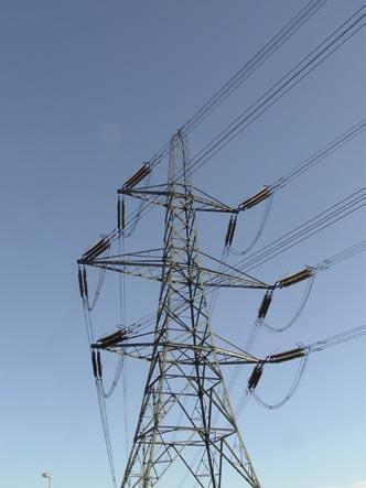
80 Transmission 80
81 Transmission Tension Insulators 82 Transmission Line Hardware 90 Distribution Line Hardware 96 81
82 Tension Insulators 82
83 Tension Insulators Introduction 84 Tension Insulators up to 52 kv 86 Tension Insulators up to 72 kv 88 83
84 Introduction Construction High strength pultruded fiber glass rod Field proven interfacial sealing Non tracking, UV resistant EVA housing Tyco Electronics Tension Insulators were built as composite insulators. They are based on Raychem s 30 years experience in the field of crosslinked polymers for medium and high voltage applications. They consist of a polymeric housing of ethylene vinyl acetate (EVA) over pultruded fiberglass rod to which galvanized steel or aluminium end fittings are attached. By molding directly over the end fitting, or by using a track resistant polyurethane, moisture ingress to the fiberglass rod is prevented. Composite Insulators are available for applications up to system voltages of 72 kv. They provide a reliable solution for power utilities and railway companies with installations in severely polluted environments all over the world. The core of a composite insulator is a pultruted fiber glass rod which provides a high mechanical strength. In a direct injection molding process a non-tracking, erosion and UV resistant polymeric housing is molded directly onto the fiberglass rod. A corrosion resistant metal fitting is crimped onto each end to the rod to provide a high mechanical strength. A new developed crimping control technology monitors the assembly process of the metal fittings and ensures that crimping forces cause no damage to the fiberglass rod while achieving a crimp that will withstand the highest possible mechanical loads. Sealed with a tracking and erosion resistant polyurethane barrier, the core is protected from deterioration due to moisture ingress. Corrosion resistant crimped end fittings 84

85 Application Composite insulators are available as tension (suspension), line post and station post insulators. For railway applications, tension and strut composite insulators are available in a large variety of configurations. The maintenance free characteristics of Raychem s EVA material have been demonstrated during service experience of more than 30 years. The Tension insulators are qualified to the requirements of the IEC New products up to 230 kv A range of High Voltage silicone tension insulators from 69 kv to 230 kv will be available shortly. These insulators will cover normal, high and extra pollution levels. They will be available with a variety of end fitting options, ball, socket, eye, clevis, tongue and Y-Clevis. They will also available with corona rings where required. 85
86 Composite Tension Insulator up to 52 kv RST-DS46R-xx General Technical Data Physical Properties Creepage Distance [mm] 1300 Dry Arc Distance [mm] 450 Type of Sheds Alternating Core Diameter [mm] 21 End Fittings Mechanical Connection Galvanised Steel Electrical Properties [kv] AC Wet Withstand Voltage 130 AC Dry Withstand Voltage 148 AC Wet Flashover Voltage 158 AC Dry Flashover Voltage 193 Impulse Withstand Voltage 310 Impulse Flashover Voltage 347 Housing Color Grey Color Red Available on request Available on request Type Specific Technical Data RST-DS46R- BS SB CC CC CT CT TC TC TT TT Physical Properties Number of Sheds Housing Material INS0532 INS0345 Available on request Available on request Available on request Available on request Available on request Available on request Available on request Available on request End Fittings Top Ball Socket Clevis Clevis Clevis Clevis Tongue Tongue Tongue Tongue Bottom Socket Ball Clevis Clevis Tongue Tongue Clevis Clevis Tongue Tongue Orientation N/A N/A parallel perpendicular parallel perpendicular parallel perpendicular parallel perpendicular Drawing INS0532 Available on request Mechanical Properties [kn] Specified Mechanical Load Routine Test Load Drawing Dimensions [mm] Available on request Available on request Available on request INS0345 Available on request Available on request Available on request ,5 37,5 37,5 37,5 37,5 37,5 37,5 37,5 A B C D E F The Clevis and Tongue fittings can be supplied in any orientation. The Ball and Socket fittings are according to the IEC A. The product range is available in pollution class II and III according to IEC 815. Available on request 86
87 Composite Tension Insulator up to 52 kv RST-DS46R-xx Example: Top: Bottom: RST-DS46R-BS Ball Socket End Fittings: Ball Socket Clevis Tongue 87
88 Composite Tension Insulator up to 72 kv RST-DS69R-xx General Technical Data Physical Properties Creepage Distance [mm] 1810 Dry Arc Distance [mm] 610 Type of Sheds Alternating Number of Sheds 18 Core Diameter [mm] 21 Housing Material Available on request End Fittings Mechanical Connection Drawing Galvanised Steel Available on request Mechanical Properties [kn] Specified Mechanical Load 75 Routine Test Load 37.5 Electrical Properties [kv] AC Wet Withstand Voltage 180 AC Dry Withstand Voltage 180 AC Wet Flashover Voltage 191 AC Dry Flashover Voltage Impulse Withstand Voltage 350 Impulse Flashover Voltage 434 Housing Color Grey Color Red Available on request Available on request Type Specific Technical Data RST-DS69R- BS SB CC CC CT CT TC TC TT TT End Fittings Top Ball Socket Clevis Clevis Clevis Clevis Tongue Tongue Tongue Tongue Bottom Socket Ball Clevis Clevis Tongue Tongue Clevis Clevis Tongue Tongue Drawing Dimensions [mm] parallel parallel parallel A B C D E F The Clevis and Tongue fittings can be supplied in any orientation. The Ball and Socket fittings are according to the IEC A. The product range is available in pollution class II and III according to IEC 815. Orientation N/A N/A parallel perpendicular perpendicular perpendicular perpendicular 88
89 Composite Tension Insulator up to 72 kv RST-DS69R-xx Example: Top: Bottom: RST-DS69R-BS Ball Socket End Fittings: Ball Socket Clevis Tongue 89
90 Hardware for Transmission Lines 90
91 Hardware for Transmission Lines Introduction, Project Support 92 Vibration Dampers 93 Spacer Dampers and Spacers 93 Pole Hardware 94 Suspension Clamps 95 Dead Ends 95 Compression Fittings 95 91

92 Introduction Project Support Tyco Electronics developed Hardware for Overhead Transmission lines since over 20 years and has a lot of field experience in these products. On the following pages we present an overview of our product ranges for Overhead Transmission Lines. Spacer Dampers Vibration Dampers Spacers Pole Hardware Suspension Clamps With the products on the following pages we want to give you an overview of available product types. For these product ranges we concern to work close together with the customers on their projects to define the right product from the wide product range. Therefore we do not present details of the products in this catalogue, which are available in different sizes and materials for a wide range of applications. If you are interested in products from the following pages, please contact your relevant sales representative. He will find together with you the correct product for your special application. Dead Ends Compression Fittings 92


93 Vibration Dampers General Recommendations Vibration dampers are designed to eliminate conductor fatigue damage and line maintenance costs by effectively diminishing aeolian vibration, thereby allowing increased line tensions. All Tyco Electronics damping devices are designed for the single purpose of reducing vibration. This unitary function is entirely different from that of protecting against: (1) stress concentrations, (2) fretting of abrasion and (3) arc-over burning. Stockbridge Vibration Dampers Dogbone Vibration Dampers Spiral Vibration Dampers The Stockbridge vibration dampers are constructed with a 7 strand messenger cable to improve the damping. Damper weight and length will be optimized for maximum efficiency. The Dogbone vibration dampers are constructed with a 19 strand messenger cable to improve damping and fatigue performance. The design of the zinc weights eliminates water entrapment. The messenger cable has improved energy dissipation at low amplitude of flexure. Spiral Vibration Dampers are exceptionally effective against high frequency aeolian vibration of EHS of Alumoweld shield wires. Spacer Dampers 2 Bundle Posilok Spacer Damper Spacer Dampers are recommended for multi-conductor bundles with industry standard spacing. The Spacer Damper is designed to withstand the forces and movements caused by transient conditions such as short circuit, differential icing, and wind loading without either causing damage themselves. 3 Bundle Posilok Spacer Damper The design accommodates both longitudinal movement of the subconductors, vertical sag differences, as well as compressive and tensile forces. The Spacer Damper can constitute a system which replaces conventional spacers and vibration dampers. 4 Bundle Bolted Spacer Damper Spacer Dampers will control both Aeolian vibration and subconductor oscillation to levels recognized as acceptable within the industry and to the customers expressed needs. Tyco Electronics will tailor the recommendations to terrain and design parameters. Posilok Spacer Posilok spacers are designed to maintain specified subconductor spacing. Furthermore, they are designed to withstand the forces and movements caused by transient conditions such as short circuit differential icing and wind loading without either causing damage to the subconductors or sustaining damage themselves. The Posilok spacer is flexible enough to allow some longitudinal movement between subconductors and yet rigid enough to restrain the subconductors under adverse conditions. They provide a smooth, unitized construction which minimizes corona and presents a low level of RIV. 93


94 Pole Hardware Yoke Plates and Clevis Eyes Ball Clevis Ball Eye Links Bow Shackles (Anchor Shackles) Ball Clevis Extension Links Ball Eye Extension Links Ball Hooks Socket Clevis Socket Tongues D Shackle Socket Clevis Extension Links Clevis Tongues Clevis Suspension Clamps Trunnion Suspension Clamps Suspension Clamp for Steel and Copper Conductors Turnbuckles Aluminium Angle Clamp The devices above are available in different designs and sizes. Other devices of pole hardware are available on request. For more details please contact your relevant sales representative. 94


95 Suspension Clamps Heliformed Suspension Unit Forged / Cast Bolted Suspension Clamp Bildqualität schlecht Suspension clamps are designed to reduce the static stresses at the support point, as well as insure that the conductor is cushioned against the dynamic stresses of aeolian vibration. They also protect the conductor in the support area against impulse and power flashover. Dead Ends Wegde Tension Clamp Bolted Tension Clamp Dead Ends are designed to fix the transmission line at the pole. There are two possibilities to fix the cable into the Clamp: the wedge and the bolted solution. Compression Fittings Full Tension Fittings Full Tension Fittings are designed to hold a minimum of 95% of the specific conductor breaking load. Bildqualität schlecht Non-Tension Fittings Non-Tension Fittings are designed to hold nominally 10% of the conductor breaking load. Spacers Spacers are designed to maintain conductor separation. 95
96 Hardware for Distribution Lines 96
97 Hardware for Distribution Lines Ties 98 Splices 98 Armor Rods 98 Line Guards 98 Heliformed Suspension Unit 98 Fiber Optic Dead Ends 99 Optical Tension Device 99 Fiber Optic Suspension Unit 99 97


98 Ties To insure proper fit and service life, it is recommended that only insulators corresponding to C Neck, F Neck, or J Neck be used. The neck diameters and groove height dimensions appear in ANSI Standard for low and medium voltage pin type insulators and also at the beginning of each listing. Ties are recommended as an improvement over Armor Rods secured with hand tie wire. Ties are available as: Longspan Ties Distribution Ties Double Support Ties Side Ties Double Support Ties Spool Ties Quick Spool Ties Splices Splices are designed for joining ACSR or repairing ACSR when damage to the core is suspected. Full Tension Splice will hold the full rated breaking strength and restore conductivity. Conductor Splices are designed as a single component outer layer assembly for sub-ehv conductor. All conductors, new or weathered, must be thoroughly scratch brushed until bright and clean and an inhibitor applied immediately prior to installation of the splice. Armor Rods Armor Rods are intended to protect the conductor on which they are being applied against bending and compression stresses, abrasion, and arc-over. The degree of protection needed on a specific line depends upon a number of factors such as line design, temperature, tension, exposure to wind flow, and vibration history on similar construction in the same area. Armor Rods should be considered as minimum protection for clamp style supports of bolted suspension arrangements. Armor Rods do not act as vibration dampers. They are designed to provide an extra degree of protection to the conductor at support points. Line Guards Line Guards are intended to protect the conductor against abrasion and arc-over and to provide repair. The degree of protection needed on a specific line depends upon a number of factors such as line design, temperature, tension, exposure to wind flow, and vibration history on similar construction in the same area. Line Guards are recommended as minimum for use with hand-tied spans of less than 300 feet in urban construction having no experience of vibration. Line Guards alone are not recommended for use in areas of suspected vibration. They are designed to provide an extra degree of protection to the conductor at support points. Heliformed Suspension Unit Heliformed suspension is intended for use on aluminium based conductors, alumoweld and galvanized steel strands. They are designed to reduce the static stresses at the support point, as well as insure that the conductor is cushioned against the dynamic stresses of aeolian vibration. They also protect the conductor in the support area against impulse and power flashover. Although Heliformed suspension provides improved protection over armor clamp or bare clamp attachments, in the case of known vibration, vibration dampers will be necessary. Consult Tyco Electronics for recommendations concerning Dogbone vibration dampers. 98


99 Fiber Optic Dead End For ADSS cable Fiber Optic dead ends may be installed once as a temporary (less than 30 days) pulling device prior to its final installation; as long as it is not stressed over 50% of its rated strength. The dead ends are sold as an assembly including reinforced rods, a dead end, clevis thimble, extension link and oval eye nut. Fiber Optic Dead End For OPGW cable The fiber optic dead end may be installed once as a temporary (less than 30 days) pulling device prior to its final installation; as long as it is not stressed over 50% of its rated strength. A ground clamp may be ordered with the dead end. Clamping over the OPDE or the OPRR assemblies is not permitted. Maximum Rated Holding Strength is 95% of the OPGW RTS. Optical Tension Device (OTD) For OPGW Fiber Cable Tyco Electronics new Optical Tensioning Device is designed for pulling OPGW fiber cable to final sag tension. Once the final sag has been achieved, a permanent type dead end device should be installed promptly, followed by the removal of the tensioning device. This device should not be subjected to sag tension for an extended time period and it should never be utilized as permanent dead end device. Fiber Optic Suspension Units The fiber optic fixed suspension unit is a low cost assembly for installing ADSS cable. The aluminium housing is joined with stainless steel roll pins, which ensure positive alignment. The housing is cushioned on the inside with an EPDM liner which is specially sized to provide excellent slip strength ability and yet not impart any undue clamping stresses on the cable. A grounding lug, consisting of a 10 mm aluminium bolt tapped in the housing, is available as an option. 99
Completing the picture
 HIGH VoltaGe cable accessories for 72 kv up to 170 kv Completing the picture based on experience is the future nkt cables GmbH nkt was established in 1891 as cable manufacturer. in 1999 nkt a/s denmark
Medium Voltage. Joints & Terminations
 57 - Cold Shrink Joints Supporting Core Radially shrinkable elastomeric splice Semi-conductive layer High permitivity insulation layer 6.6/11/(12) kv 3M QS1000 is a one-piece cold shrink joint body manufactured
ACCESSORIES FOR LPOF, HPPT AND XLPE HIGH VOLTAGE CABLE SYSTEMS PRODUCT CATALOGUE
 ACCESSORIES FOR LPOF, HPPT AND XLPE HIGH VOLTAGE CABLE SYSTEMS PRODUCT CATALOGUE hvgrid-tech designs and manufactures high voltage cable accessories for all types of cable systems, ranging from 69 kv to
TE s RAYCHEM HIGH VOLTAGE CABLE ACCESSORIES
 NRGY /// HIGH VOLTG L SSORIS UP TO 245 KV T s RYHM HIGH VOLTG L SSORIS up to 245 kv 3 ontent I. High Voltage able T onnectivity 4 High Voltage able ccessories 5 Our core ompetencies 6 Services 7 Heat-Shrinkable
H e a t s h r i n k P r o d u c t G u i d e
 P o w e r P r o d u c t s H e a t s h r i n k P r o d u c t G u i d e Introduction HellermannTyton is a world leader in providing systems and solutions for heatshrink applications. HellermannTyton utilises
High Voltage Accessories up to 72.5 kv
 High Voltage Accessories up to 72.5 kv Technical instructions and application information The data given were determined diligently, but do not release our customers of the duty to carry out tests themselves
CLICK-FIT. High Voltage Accessories for Extruded Cables
 CLICK-FIT High Voltage Accessories for Extruded Cables Linking the future As the worldwide leader in the cable industry, Prysmian Group believes in the effective, efficient and sustainable supply of energy
High Voltage Cable Accessories Product catalog
 High Voltage Cable Accessories Product catalog 1300 780 831 info@cablegrid.com.au www.cablegrid.com.au Table of Contents page 1 HV Terminations 3 Dry type plug in GIS and Transformer terminations 5 GIS/Transformer
power cable accessories
 power cable accessories kv up to 4 kv Completing the picture based on experience is the future nkt cables GmbH NKT was established in 89 as cable manufacturer. In 999 NKT A/S Denmark merged with Felten
CABLE SYSTEMS. Accessories and Systems for Medium and High-Voltage Cables up to 300 kv.
 MV-CONNEX, HV-CONNEX, IXOSIL Terminations, IXOSIL MSA Slip-on Joint Boxes CABLE SYSTEMS Accessories and Systems for Medium and High-Voltage Cables up to 300 kv. Welcome to the CABLE SYSTEMS Centre of Competence.
OIP Transformer Outdoor Bushings Type COT(C) 125 COT (C) kV to 550kV up to 5000A IEC
 125 COT (C) kV to 550kV up to 5000A IEC") OIP Transformer Outdoor Bushings Type COT(C) 125 COT (C) 1800 24kV to 550kV up to 5000A IEC 60137-2008 Features If you need any transformer bushing proven in operation conditions around the world, Trench
OIP Transformer Outdoor Bushings Type COT(C) 125 COT (C) 1800 24kV to 550kV up to 5000A IEC 60137-2008 Features If you need any transformer bushing proven in operation conditions around the world, Trench
1ZSC AAA EN, REV. 7. Transformer bushings type GSBK Technical guide
 1ZSC563-AAA EN, REV. 7 Transformer bushings type GSBK Technical guide Original instruction The information provided in this document is intended to be general and does not cover all possible applications.
1ZSC AAA en, Rev. 6. Resin impregnated paper bushing, oil to SF 6., type GSBK Technical guide
 1ZSC563-AAA en, Rev. 6 Resin impregnated paper bushing, oil to SF 6, type GSBK Technical guide Original instruction The information provided in this document is intended to be general and does not cover
Nexans Network Solutions Div. Euromold
 Catalogue 2012 Nexans Network Solutions Div. Euromold COMPANY PRESENTATION EUROMOLD Euromold is the leading European specialised designer, manufacturer and distributor of prefabricated cable accessories
Resin Impregnated Paper Bushing, Oil to SF 6. , Type GSBK
 1ZSC563-AAA en, Rev. 2 Resin Impregnated Paper Bushing, Oil to SF 6, Type GSBK Technical guide This Technical Guide has been produced to allow transformer manufacturers, and their designers and engineers,
CAST RESIN DISTRIBUTION TRANSFORMERS 2016 EDITION
 CAST RESIN DISTRIBUTION TRANSFORMERS 2016 EDITION TMC TRANSFORMERS - GLOBAL NETWORK UK & IRELAND SPAIN NORTH AMERICA & CANADA GERMANY SWITZERLAND BENELUX & AUSTRIA ITALY POLAND INDIA CENTRAL & SOUTH AMERICA
High-Voltage Cable Accessories. 72 kv up to 245 kv. nkt.com
 High-Voltage Cable Accessories 72 kv up to 245 kv nkt.com 1 Table of contents General NKT: The Profile... 3 The product range: High-Voltage Cable Accessories... 4 XLPE-Cable Terminations THV 72-145...
HVS S 15kV Class
 Product HVS-3-1580S 15kV Class Transition Splice for 3/C to 3/C Extruded Dielectric (Poly/EPR) Power Cables Raychem Corporation Electrical Products 8000 Purfoy Road Fuquay-Varina, NC 27526 PII-54864, Rev
Bushings for High Voltage AC Applications
 Bushings for High Voltage AC Applications Selection guide 1ZSE 2750-100 en, Rev. 3, 2006-03-15 During selection of for high voltage applications several important factors have to be considered to ensure
B kv T&D GAS INSULATED SWITCHGEAR
 GAS INSULATED SWITCHGEAR B 105 170 300 kv The increasing demand for electrical power in cities and industrial centers necessitates the installation of a compact and efficient distribution and transmission
OIP Transformer Outdoor Bushings Type COT(C) 125 COT (C) kV to 550kV up to 5000A IEC
 125 COT (C) kV to 550kV up to 5000A IEC") OIP Transformer Outdoor Bushings Type COT(C) 125 COT (C) 1800 24kV to 550kV up to 5000A IEC 60137-2008 Features If you need any transformer bushing proven in operation conditions around the world, Trench
OIP Transformer Outdoor Bushings Type COT(C) 125 COT (C) 1800 24kV to 550kV up to 5000A IEC 60137-2008 Features If you need any transformer bushing proven in operation conditions around the world, Trench
1ZSE EN, REV. 4. Wall bushings type GSA-AA Technical guide
 1ZSE 2750-112 EN, REV. 4 Wall bushings type GSA-AA Technical guide Original instruction The information provided in this document is intended to be general and does not cover all possible applications.
a Nexans company Catalogue 2008
 a Nexans company Catalogue 2008 EUROMOLD COMPANY PRESENTATION EUROMOLD Euromold is the leading European specialised designer, manufacturer and distributor of prefabricated cable accessories for medium
INTRODUCTION. The plug-in connection on the cables and lightning arrestors, allows for easy installation and replacement.
 INTRODUCTION The Power Systems 44 kv MiniSub TM is the most compact system at this voltage available. Utilizing a deadfront termination and lightning arrestor setup, it eliminates the line top or side
Energy Division. PCA Single Column Polymeric Surge Arrester
 Energy Division PCA Single Column Polymeric Surge Arrester Bowthorpe EMP pioneered the development of the polymeric composite housed surge arrester in the early 1980 s and since 1986 has a proven service
TE S RAYCHEM RSTI-CC-58 SCREENED, SEPARABLE COUPLING SYSTEM
 Industry photo: should be a the same image as larger industry photo. Either a different crop or different angle. industry photo. This image and the one above should be different versions of the same photo
UNDERGROUND TRANSMISSION SOLUTIONS
 UNDERGROUND TRANSMISSION SOLUTIONS PRODUCT CATALOG SWC002-6_UndergroundTransmissionCatalog_R.indd SOUTHWIRE SOLUTIONS FOR UNDERGROUND TRANSMISSION CABLES XLPE Cables 69 through 400 kv with Copper and Aluminum
3EQ Composite Housed Surge Arresters Saving Money and Space, Gaining Reliability
 3EQ Composite Housed Surge Arresters Saving Money and Space, Gaining Reliability Power Transmission and Distribution 1 A perfect Combination of Cost-Savings, Safety and Reliability 3EQ Surge Arresters:
3EQ Composite Housed Surge Arresters
 Power Transmission and Distribution 3EQ Composite Housed Surge Arresters Saving Money and Space, Gaining Reliability A perfect Combination of Cost-Savings, Safety and Reliability 3EQ Surge Arresters: Your
Mechanical Connectors, Lugs and Repair Sleeves for Medium Voltage Cable Accessories up to 42 kv
 Mechanical Connectors, Lugs and Repair Sleeves for Medium Voltage Cable Accessories up to 42 kv Mechanical Connectors, Lugs and Repair Sleeves for Medium Voltage Cable Accessories up to 42 kv Features
QTII (X) Series Silicone Rubber Cold Shrink Termination Kits
 Series Silicone Rubber Cold Shrink Termination Kits") QTII (X) Series Silicone Rubber Cold Shrink Termination Kits For MV Armored/Non-Armored Cables up to 36kV DATA SHEET Update: August 2006 1. Product Description The 3M QTII (X) Series are Silicone Rubber
QTII (X) Series Silicone Rubber Cold Shrink Termination Kits For MV Armored/Non-Armored Cables up to 36kV DATA SHEET Update: August 2006 1. Product Description The 3M QTII (X) Series are Silicone Rubber
Silicone Suspension/Tension Insulator 120kN. up to LIWV 450kV (BIL)
") Silicone Suspension/Tension Insulator 120kN up to LIWV 450kV (BIL) CABLE SYSTEMS FOR ENERGY & ROLLING STOCK APPLICATIONS MV Silicone Tension Insulators The high tensile strength of glass fibre has been
Silicone Suspension/Tension Insulator 120kN up to LIWV 450kV (BIL) CABLE SYSTEMS FOR ENERGY & ROLLING STOCK APPLICATIONS MV Silicone Tension Insulators The high tensile strength of glass fibre has been
BOWTHORPE EMP MEH SURGE ARRESTERS (IEC) ENERGY /// MEH SURGE ARRESTERS IEC
 ENERGY /// MEH SURGE ARRESTERS IEC") BOWTHORPE EMP MEH SURGE ARRESTERS (IEC) GENERIC TECHNICAL DATA Maximum system voltage U m 800 System voltage U s 750 Nominal discharge current ka 20 High current impulse (4/10 µs) ka 100 Arrester class
BOWTHORPE EMP MEH SURGE ARRESTERS (IEC) GENERIC TECHNICAL DATA Maximum system voltage U m 800 System voltage U s 750 Nominal discharge current ka 20 High current impulse (4/10 µs) ka 100 Arrester class
Transformer High Current Bushings Type CFPT & CFCT 36kV up to 40kA IEC
 Transformer High Current Bushings Type CFPT & CFCT 36kV up to 40kA IEC 60137-2008 High current bushings for transformer Features Bushing Type CFPT version Porcelain Insulator Trench RIG technology for
Power Voltage Transformers for Air Insulated Substations
 Power Voltage Transformers for Air Insulated Substations Introduction Trench Power Voltage Transformers (Power VTs) combine the attributes of an inductive voltage transformer with the application of a
Installation Instruction EPP /02. Terminations for Screened Single Core Polymeric Insulated Cables up to 24 kv without Armour
 R Installation Instruction EPP-0778-11/02 Terminations for Screened Single Core Polymeric Insulated Cables up to 24 kv without Armour Type: IXSU-F / OXSU-F Tyco Electronics Raychem GmbH Energy Division
High Voltage and Extra High Voltage Cables
 High Voltage and Extra High Voltage Cables GUIDE TO THE SELECTION OF EHV AND HV CABLES EHV and HV cables are specially designed on the basis of the project data. To determine appropriate design of a high
DURESCA Busbar system. For indoor and outdoor applications, type DE / type DG DURESCA
 DURESCA Busbar system For indoor and outdoor applications, type DE / type DG DURESCA DURESCA Busbar system Swiss quality combined with global experience PRODUCT OVERVIEW Moser Glaser General description
Shielded surge arresters
 Shielded surge arresters Nexans, worldwide leader for the cable industry Total sales of billion euros in 2009 The most complete range of cables and cabling systems Plants in 39 countries 22,700 employees
013 : 2009 CEB SPECIFICATION MOULDED CASE CIRCUIT BREAKERS
 013 : 2009 CEB SPECIFICATION MOULDED CASE CIRCUIT BREAKERS FOR OVERHEAD NETWOKS CEYLON ELECTRICITY BOARD SRI LANKA Specification for MOULDED CASE CIRCUIT BREAKERS FOR OVERHEAD NETWOKS CEB Specification
Raychem CSJA Safety Instructions. Safety Instructions. Customer Service. Kit Contents. Installation Instructions
 Raychem CSJA 1521 Cold-Shrinkable Splice for single core polymeric insulated (XLPE-EPR) cables up to 15kV for tape, wire, Unishield, LC shield, JCN, and flat strap neutral cable UniShield is a trademark
SUSPENSION 04 CLAMPS
 SUSPENSION CLAMPS 04 4 SUSPENSION CLAMPS 57 Contents General... 58 Suspension clamp trunnion type, forged,... 63 Suspension clamp trunnion type, forged, with bigger angle of deflection, for aluminium based
Resin Impregnated Paper Bushing, Oil to Air, Type GSB Technical guide
 1ZSC000563-AAC en, Rev. 2 Resin Impregnated Paper Bushing, Oil to Air, Type GSB Technical guide This Technical Guide has been produced to allow transformer manufacturers, and their designers and engineers,
Lifting Instructions for 1336 PLUS and FORCE D Frame Drives
 Installation Instructions Lifting Instructions for 1336 PLUS and FORCE D Frame Drives This publication will guide you through the steps needed to properly lift and mount the following drives: 1336 PLUS
Nexans Switzerland. Global expert in cables and cabling system. Cossonay Production Plant
 P o w e r C a b l e A c c e s s o r i e s Global expert in cables and cabling system Formed from Alcatel Cables and Components, Nexans inherits 100 years professional experience in manufacturing cables
3M Cold Shrink 1/C Transition Splice Kit QS-III, 5510A-1T-PILC Series
 3M Cold Shrink 1/C Transition Splice Kit QS-III, 5510A-1T-PILC Series Data Sheet March 2011 Description 3M Cold Shrink 1/C Transition Splice Kits QS-III, 5510A-1T-PILC Series (which includes 5513A-1T-PILC,
 Technical Guarantees For Electrical Materials & Equipments 1 Technical Guarantees No. IDT_1600 22/0.4 KV Low Losses, 3 phase, Indoor Distribution Transformer 1600 KVA Rating No Description Unit Requirements
INTERFACE E - 5/8" MEDIUM VOLTAGE SEPARABLE CONNECTORS AND BUSHINGS CATALOGUE 2017
 INTERFACE E - 5/8" MEDIUM VOLTAGE SEPARABLE CONNECTORS AND BUSHINGS CATALOGUE 2017 NEXANS NETWORK SOLUTIONS DIV. EUROMOLD COMPANY PRESENTATION EUROMOLD Euromold is the leading European specialised designer,
1ZSE en, Rev. 3. Wall bushings, type GSA-AA Technical guide
 1ZSE 2750-112 en, Rev. 3 Wall bushings, type GSA-AA Technical guide Original instruction The information provided in this document is intended to be general and does not cover all possible applications.
kv А
 66-220 kv 2000-4000 А Publication 11.2011 "IZOLYATOR" PLANT performs design, manufacturing, warranty and post-warranty service of high-voltage bushings for various applications. The enterprise is the main
NXPLUS C Single busbar. Maintenance-free for lifetime
 NXPLUS C Single busbar Maintenance-free for lifetime Energy Distribution Welcome! Page 2 Content Overview Technical data Typicals Panel design Circuit-Breaker panel Busbar Operation Metering Low-voltage
THORNE & DERRICK UK TEL FAX TEL FAX
 a Nexans company Catalogue 2006 EUROMOLD COMPANY PRESENTATION EUROMOLD Euromold is the leading European specialised designer, manufacturer and distributor of prefabricated cable accessories for medium
Power cable accessories catalogue
 Power cable accessories catalogue MV Terminations & MV Joints Excellence in Training Obtain an accreditation in a wide range of joints and terminations. Courses available in low voltage, medium voltage
UNDERGROUND TRANSMISSION SOLUTIONS PRODUCT CATALOG
 UNDERGROUND TRANSMISSION SOLUTIONS PRODUCT CATALOG SOUTHWIRE SOLUTIONS FOR UNDERGROUND TRANSMISSION CABLES SERVICES XLPE Cables 69 through 400 kv with Copper and Aluminum conductors through 6,800 kcmil
GAS INSULATED VOLTAGE TRANSFORMERS.
 GAS INSULATED VOLTAGE TRANSFORMERS. This document may be subject to changes. Contact ARTECHE NISSIN to confirm the characteristics and availability of the products described here. CONTENTS 1. Presentation
Medium Voltage Catalogue 2013
 Medium Voltage Catalogue 2013 D813 SAP.Nr. 198693 1112 Medium Voltage 2013 Data, values and illustrations given in this documentation are correct and reliable according to the current state of our knowledge.
JOSLYN. Underground Cable Accessories. Table of Contents. JPT/JIPT Polymer Terminations. ShrinkTite Sealing Kits. Easy-On II Terminations
 Underground Cable Accessories JOSLYN Table of Contents JPT/JIPT Polymer Terminations 15kV, 25kV & 35kV ShrinkTite Sealing Kits 1kV In-Line Splice Sealing Kit Cable Jacket Sealing Kit Easy-On II Terminations
Extraction arms for every type of application
 1 Extraction arms for every type of application 2 Improved workspaces within arm s reach A workspace free from dust, hazardous particles, fumes and exhaust is good in many ways. It improves the working
Terminations. 3M Cold Shrink Terminations FAX TERMINATIONS. Glossary of Terminations Terms 263 Cable Types for Terminating 264 3M
 Terminations Glossary of Terminations Terms 263 Cable Types for Terminating 264 3M Cold Shrink QT-III Silicone Rubber Terminations 265 3M Cold Shrink Termination QT-III 69 kv/72,5 kv 270 3M Cold Shrink
1ZSE EN, REV. 7. Oil SF 6. bushings type GOEK Technical guide
 1ZSE 2750-106 EN, REV. 7 Oil SF 6 bushings type GOEK Technical guide Original instruction The information provided in this document is intended to be general and does not cover all possible applications.
Submarine Power Cables
 Submarine Power Cables Submarine Power Cables Since decades Nexans plant in Hannover is specialised in the design, production and installation of low and medium voltage submarine power cables required
Product presentation CPT tech Jason Evershed, ABB Transformer Components, May 21st Dry-type transformers Innovative Technology
 Product presentation CPT tech Jason Evershed, ABB Transformer Components, May 21st 2014 Dry-type transformers Innovative Technology What is a dry transformer? ABB manufactures a transformer which does
026-2 : 1996 CEB STANDARD
 026-2 : 1996 CEB STANDARD COMPRESSION CONNECTORS & TERMINATIONS FOR OVERHEAD LINE CONDUCTORS CEYLON ELECTRICITY BOARD SRI LANKA CONTENTS 1. Scope 2 2. System Parameters 2 3. Service Conditions 2 4. Applicable
MV TERMINATIONS. INDOOR SINGLE CORE TERMINATION - ELTI-1C for polymeric cables - Slip-on termination - Modular type APPLICATION STANDARDS
 MEDIUM VOLTAGE MV TERMINATIONS INDOOR SINGLE CORE TERMINATION - ELTI-1C APPLICATION Utilisation indoor. in boxes and compact switchgears. in terminal boxes located outdoor and subject to condensation.
3AP1 DTC for 145 and 245 kv
 The Hybrid Solution 3AP1 DTC for 145 and 245 kv siemens.com/answers Solutions for switchgears and substations fully encapsulated h y b r i d Grade of encapsulation partly encapsulated not encapsulated
Railway Infrastructure. Competent Solutions for Electric Railways and Tramways. the power connection THE PFISTERER GROUP
 Competent Solutions for Electric Railways and Tramways THE PFISTERER GROUP the power connection Solutions for Today s and Future Challenges Reliable and maintenance-free infrastructure provides the basis
WRSS Wraparound Repair Sleeve Installation Instructions
 WRSS Wraparound Repair Sleeve Installation Instructions TECP-30-263. Issue 1. 4/2016 1.0 General Product Information This practice provides information regarding the description and use of Raychem s WRSS
B kv Gas-insulated Substations
 72.5 145 kv Gas-insulated Substations The increasing demand for electrical power in cities and industrial centres requires the installation of a compact and efficient distribution and transmission network.
Installation Instruction Heatshrink Termination For 3 Core Polymeric Cables 7.2kV to 36kV
 Installation Instruction Heatshrink Termination For 3 Core Polymeric Cables 7.2kV to 36kV * PLEASE READ INSTRUCTIONS THOROUGHLY BEFORE PROCEEDING * INDOOR OUTDOOR Download free QR code scanning software
CONNECTORS AND FITTINGS
 Industry photo: should be a the same image as larger industry photo. Either a different crop or different angle. Human photo. Can be environmental/ documentaty style or portrait of engineer. Human photo.
a Nexans company Medium voltage symmetrical separable connectors - Interface C -
 a Nexans company Medium voltage symmetrical separable connectors - Interface C - Catalogue 2011 Nexans Network Solutions Div. Euromold COMPANY PRESENTATION EUROMOLD Euromold is the leading European specialised
Transformer Bushings Type COT COT kv to 245 kv up to 3150 A IEC 137
 Transformer Bushings Type COT 5... COT 050 4 kv to 45 kv up to A IEC 37 Features If you need any transformer bushing proven in operation conditions around the world, Trench has it! experience in bushing
Power and Distribution Transformers
 Power and Distribution Transformers VRT Power Ltd. We Enable Energy VRT is a modern manufacturer for high-performance oil-immersed power transformers up to 800 MVA 500 kv. Customized design and the development
TIDALFLUX 2300 F Quick Start
 Quick Start Electromagnetic flow sensor for partially filled pipes The documentation is only complete when used in combination with the relevant documentation for the signal converter. KROHNE CONTENTS
BOWTHORPE EMP MCA/MDA SURGE ARRESTERS (IEC) ENERGY /// MCA/MDA SURGE ARRESTERS IEC
 ENERGY /// MCA/MDA SURGE ARRESTERS IEC") BOWTHORPE EMP MCA/MDA SURGE ARRESTERS (IEC) GENERIC TECHNICAL DATA MCA MDA Maximum system voltage U m 420 550 System voltage U s 400 500 Nominal discharge current ka 10 20 High current impulse (4/10 µs)
BOWTHORPE EMP MCA/MDA SURGE ARRESTERS (IEC) GENERIC TECHNICAL DATA MCA MDA Maximum system voltage U m 420 550 System voltage U s 400 500 Nominal discharge current ka 10 20 High current impulse (4/10 µs)
Portable Compressors MOBILAIR M 122 With the world-renowned SIGMA PROFILE Free air delivery 11.1 m³/min
 www.kaeser.com Portable Compressors MOBILAIR M 122 With the world-renowned SIGMA PROFILE Free air delivery 11.1 m³/min Worldwide sales and service network KAESER is one of the world s foremost compressor
045 : 2000 CEB STANDARD
 045 : 2000 CEB STANDARD LOW VOLTAGE FUSE SWITCH DISCONNECTOR CEYLON ELECTRICITY BOARD SRI LANKA Specification for LOW VOLTAGE FUSE SWITCH DISCONNECTOR CEB Standard 045 : 2000 CEYLON ELECTRICITY BOARD No.
PLASTIC WELDING. New! TRIAC AT. Intelligent and robust.
 PLASTIC WELDING TRIAC AT New! Intelligent and robust. Hot air tool TRIAC AT The new TRIAC AT is an intelligent yet robust hot air tool for welding and shrinking plastic. It is designed for the needs of
Accessories. Introduction. Cable Hangers LINE PRODUCTS TRANSMISSION
 Accessories Introduction While a number of cable related accessories are available on the market, RFS components are of the highest quality and are designed to provide years of trouble-free service. Together
High Voltage Technology & Testing
 The Power of Trust. The Future of Energy. HIGH VOLTAGE TESTING Qualification testing, condition assessment, and forensic analysis Manufacturers and utility users of high-voltage electrical equipment face
a Nexans company Catalogue 2009
 a Nexans company Catalogue 2009 EUROMOLD COMPANY PRESENTATION EUROMOLD Euromold is the leading European specialised designer, manufacturer and distributor of prefabricated cable accessories for medium
Better sealing solutions for reciprocating compressors
 Better sealing solutions for reciprocating compressors Experience and know-how the basis for innovation Rings and packings are critical components for the service life of reciprocating compressors. Therefore
ABB Transformers For reliability, efficiency and minimum environmental impact
 Avicenna Nugroho, Regional Marketing Specialist, Surabaya, 30 October 2014 ABB Transformers For reliability, efficiency and minimum environmental impact Introduction BU Transformers November 10, 2014 Slide
PLASTIC WELDING. New! TRIAC AT. Intelligent and robust.
 PLASTIC WELDING TRIAC AT New! Intelligent and roust. TRIAC AT features Suitale for the work site Closed loop controlled temperature Open loop controlled air volume Intelligent «e-drive» operating unit
MEDIUM VOLTAGE TERMINATIONS
 CAT010509- Rev 1. 2009 INERTIA- REPL INC. All rights reserved Printed January 2009 MEDIUM VOLTAGE TERMINATIONS General Information about Heat-shrinkable Terminations 3.00 T50NS Terminations for 5-8 kv,
Joined Forces Extensive product portfolio and technologies. Cable Accessories from 1 kv to 550 kv. nkt.com
 Joined Forces Extensive product portfolio and technologies Cable Accessories from kv to 550 kv nkt.com NKT manufacturing and testing equipment ensures high quality products. Concentrated Competence With
a Nexans company Catalogue 2007
 a Nexans company Catalogue 2007 EUROMOLD COMPANY PRESENTATION EUROMOLD Euromold is the leading European specialised designer, manufacturer and distributor of prefabricated cable accessories for medium
High-current and generator switchgear from Siemens siemens.com/generatorswitchgear
 High performance for the power supply of tomorrow High-current and generator switchgear from Siemens siemens.com/generatorswitchgear Generator switchgear With matured vacuum switching technology As one
LIST OF EDD DESCRIPTION/ SPECIFICATION AS 19 TH OCTOBER 2016
 No Description/ Specification Amendment 1 EDD 1 :2008 11/0.415 kv Distribution Transformer, Oil Filled - 2 ED 2 :1987 The Galvanization of Iron and Steel, Articles Other Than Steel Wire - 3 ED 3 :1979
HV/EHV Extruded Cable Systems
 Colloquium on HV Insulated Cables, New Delhi October 13 th, 2017 HV/EHV Extruded Cable Systems Mohamed MAMMERI (General Cable) Balza, Xabier (General Cable) HV-EHV UG Cable System A full range of cables
Solid Dielectric, Three Phase Reclosers CATALOG VS11
 Solid Dielectric, Three Phase Reclosers Providing electronic, three phase overcurrent protection for systems rated through 38kV, 800A continuous current, 12.5kA symmetrical interrupting Reliable performance
Pretest Module 29 High Voltage Unit 1
 Pretest Module 29 High Voltage Unit 1 1. Is a person qualified to work on high-voltage installations when this module is completed? 2. What is the code definition of high-voltage? 3. What is the IEEE definition
Cold Shrink QS T Trifurcating Transition Splice Kit
 Cold Shrink QS2012-13-3T Trifurcating Transition Splice Kit Instructions IEEE Std. 404-1993 15 kv Class 110 kv BIL Completed Splice Cable Size Range Requirements PILC 500 kcmil Conductor Size (240 mm 2
3EK7 Medium Voltage Silicone Insulated Surge Arresters
 3EK7 Medium Voltage Silicone Insulated Surge Arresters Power Transmission and Distribution Setting new Standards The 3EK7 s mechanical features: Glass-collared MOV, Silicone rubber housing, FRP rods and
QS-III. 5513A, 5514A, 5515A and 5516A 15 kv Cold Shrink Inline Splice Kits. Data Sheet CAUTION. 1. Product Description. 2. Applications.
 QS-III 5513A, 5514A, 5515A and 5516A 15 kv Cold Shrink Inline Splice Kits Data Sheet Tape Shield Wire Shield UniShield Kit Contents: 1 Cold Shrink Silicone Rubber Splice Body 1 Cold Shrink Adapter Tube
3M Cold Shrink 3-Conductor Inline Splice Kits QS-III 5786A- MT, 5787A-MT and 5788A-MT 25/28 kv for use with Armored and Non- Armored 3/C Cable
 3M Cold Shrink 3-Conductor Inline Splice Kits QS-III 5786A- MT, 5787A-MT and 5788A-MT 25/28 kv for use with Armored and Non- Armored 3/C Cable Data Sheet September 2010 Description 3M Cold Shrink 3-Conductor
MODERNISATION SOLUTIONS. MRM W Line. TIME FOR A FACE-LIFT!
 MODERNISATION SOLUTIONS TIME FOR A FACE-LIFT! ADVANCED FEATURES WITTUR SOLUTION FOR MODERNISATION The, Wittur flexible machine roomless electric lift, offers an ideal solution for new lifts in existing
Product presentation CPT tech Jason Evershed, ABB Transformer Components, May 21st New RIS transformer bushings The paper-free solution
 Product presentation CPT tech Jason Evershed, ABB Transformer Components, May 21st 2014 New RIS transformer bushings The paper-free solution Transformer condenser bushings Why a new technology? To preserve
35-kV Thru-Bushings F Series (bolt-in) for Air-Insulated to Air-Insulated Service 200 Amp, 600 Amp, 900 Amp and 1250 Amp
 for Air-Insulated to Air-Insulated Service 200 Amp, 600 Amp, 900 Amp and 1250 Amp") Page 1 2018 Equipment Connection Bus Bar, or Grounded Metal Equipment Plate F Series Mounting Holes ELRIM Cycloaliphatic Epoxy Provides: Nontracking, self-scouring, nonweathering performance Superior dielectric
Page 1 2018 Equipment Connection Bus Bar, or Grounded Metal Equipment Plate F Series Mounting Holes ELRIM Cycloaliphatic Epoxy Provides: Nontracking, self-scouring, nonweathering performance Superior dielectric
High Voltage Surge Arresters Station Class
 Power Transmission and Distribution High Voltage Surge Arresters Station Class Product Overview High Voltage High Protection Just as the Golden Gate Bridge has successfully defied all winds, weather and