OIP Transformer Outdoor Bushings Type COT(C) 125 COT (C) kV to 550kV up to 5000A IEC
|
|
|
- Gabriella Briggs
- 5 years ago
- Views:
Transcription


")

1 OIP Transformer Outdoor Bushings Type COT(C) 125 COT (C) kV to 550kV up to 5000A IEC


2 Features If you need any transformer bushing proven in operation conditions around the world, Trench has it! experience in manufacturing of bushings for more than 100 years capacitive fine graded oilpaper insulation with long experience computer optimized electrical field distribution proven high electrical withstand against transient or impulse stresses excellent long term stability due to extremely low partial discharge and power loss factor oil immersed part covered by epoxy resin tube providing high impact resistance available with porcelain or composite insulator on air side inclination in service up to 30 from vertical. For COT(C) 125 and COT(C) 170 even horizontal operation is possible horizontal transport for all types possible tan α and PD-values more than twice as good as requested by IEC current rating can easily be increased by exchanging the cable bolt with a removable split conductor on existing bushing electrode embedded in the lower epoxy resin part - avoids external shielding - reduces distance to ground - lower transformer costs To preserve our environment the free oil volume in COT-bushings is minimized Transformer Bushings Type COT(C) 125 to COT(C) 1800 porcelain cemented into flange provides higher mechanical strength than level II of IEC Certified ISO 9001 Substitute for E &E Page 2 / _ _00
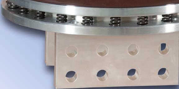
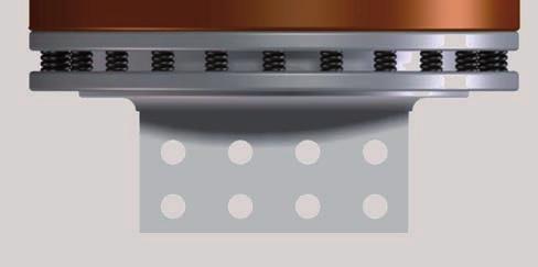
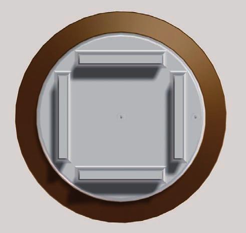
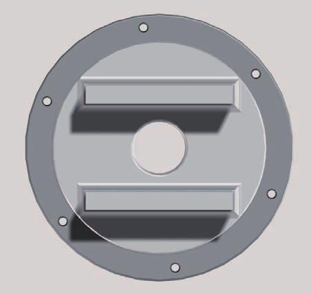
3 Design 10 Cut view General design 1 1 Top terminal Terminal (Aluminium or Copper) for connection of overhead lines or bus bars and arcing horns. Trench design provides a maintenance free termination and ensures that the connection will not become loose in service. 2 Assembly The whole bushing is tightened together by the central tube or conductor. 3 Head Al-casted head with oil expansion chamber and oil level indicator. The chamber is hermetically sealed against several environmental conditions. 4 Oil filling COT bushings are filled with dried, degassed insulating mineral oil. 5 Insulator Porcelain insulator made of high grade electrotechnical porcelain according to IEC The insulator is connected to the mounting flange using cement and sealed with O-ring gasket. instead of porcelain a composite insulator is also available. 6 Active part The active part is made of oilimpregnated wide band paper with layers of aluminium foil to control the electrical field radially and axially. Depending on the current rating, the paper and foil are wound on either a central tube or solid conductor 7 Flange Mounting flange with integrated test tap made of corrosion free aluminium alloy, machined to ensure an excellent seal between the bushing and the transformer. 8 CT-Pocket If current transformers are required on the bushing, the ground sleeve can be extended. 9 Oil side end The insulator on the oil side is made of an epoxy resin tube. It is designed to stay installed during the in-tank drying process of the transformer and can withstand temperatures up to 130 C. 10 End-shielding For voltages starting between 52kV & 300kV a special aluminium electrode is casted into the end of the epoxy resin tube. This end shielding controls the electrical field strength in this area to ground Substitute for E &E Page 3 / _ _01
4 One of several TRENCH winding machines Test tap for C and tan measurement Substitute for E &E Page 4 / _ _00

5 High voltage test laboratory Epoxy insulator with embedded end shield Cut view Insulation See page 16 Cable Substitute for E &E Page 5 / _ _01
6 Type COT Type COT N N Type Type Highest voltage (Um) Highest voltage (Um) Maximum phase to earth voltage Maximum phase to earth voltage Bushing Dry Power frequency voltage Bushing withstand Dry (AC) Power frequency voltage withstand (AC) Transformer Power frequency voltage Transformer withstand (AC) Power frequency voltage Lightning Impulse withstand voltage Lightning (BIL) Impulse withstand voltage (BIL) Switching Impulse wet (SIL): 250/2500µs withstand (AC) Switching Impulse wet (SIL): 250/2500µs Rated current (Ir) mm² kv kv kv kv kv kv A mm mm mm kg N mm mm² kv kv kv kv kv kv A mm mm mm kg N mm 01 COT / 800 cable COT / 800 cable 1000 cable ) rem.co-cond. cable 1 ) 2 ) fixed rem.co-cond. 2 ) fixed fixed Co-cond. Co-cond fixed fixed Co-cond. Co-cond COT / cable fixed Co-cond * COT / cable cable 1 ) *1116 * rem.co-cond. cable 1 ) 2 ) *1116 * fixed rem.co-cond. 2 ) - 35 *1116 * fixed fixed Co-cond. Co-cond. - - *1116 * fixed fixed Co-cond. Co-cond. - - *1116 * COT / 800 cable fixed Co-cond. - * cable 1 ) COT / 800 cable rem.co-cond. 2 ) cable 1 ) fixed Co-cond rem.co-cond. 2 ) fixed Co-cond fixed Co-cond fixed Co-cond fixed Co-cond COT , / 800 cable fixed 1000 cable 1 Co-cond ) COT , / rem.co-cond. cable 2 ) fixed cable Co-cond. ) fixed rem.co-cond. 2 ) fixed fixed Co-cond. Co-cond COT / cable fixed Co-cond cable fixed 1 ) Co-cond COT / rem.co-cond. cable 2 ) fixed cable Co-cond. ) fixed rem.co-cond. 2 ) fixed fixed Co-cond. Co-cond Comments 29 related to columns 1 33: 04: Bushings test voltage 2500 at 50Hz fixed 60 sec. Co-cond : 30 1 ) Class F insulation 2 ) Removable solid rod copper 3150 conductor fixed Co-cond. Connection - system see pages 17 to Connection to Transformer Cable cross section Conductor 11: Extension for current transformer (other extensions on request) 13: * 31mm/kV in standard Comments related to columns 1 33: 04: Bushings test voltage at 50Hz 60 sec. Rated current (Ir) Connection to Transformer CT Space L4 see fig.3 page 12 Cable cross section Conductor Standard: 0, 300, 500 CT AD Space Arcing L4 distance see fig.3 (min.) page 12 Standard: 0, 300, 500 AD Arcing distance (min.) Standard creepage distance Standard creepage distance Mass Approx. 25 mm / kv 25mm/kV 25 25mm/kV / kv 25mm/kV Mass Cantilever Approx. test load (min) 25mm/kV Cantilever test load (min) 09: 1 ) Class F insulation 2 ) Removable solid rod copper conductor Connection system see pages 17 to 23 11: Extension for current transformer (other extensions on request) 13: * 31mm/kV in standard Substitute for E &E Page 6 / _ _00
7 Type COT Type COT Rated current (Ir) Rated current (Ir) D 7 see D L L 1 L 2 L D 2 D 3 D 4 D 5 D 6 min 7 øt n e fig. L L 1 L 2 L 3 L 6 L 7 D D 2 D 3 D 4 D 5 D 6 min øt n e A A mm mm mm mm , 13: 1543 Brown glazed 230 porcelain, 1313 other colours - and , 17: L 1 depends 240 on 231 L 4. The values 170 in the 60 table are - valid Other creepage 230 distances 1323 upon request for L 4= 335 0mm. If 242 L 4>0mm 170 add L 4 to 60 L 1 and L. - 15: According to IEC 137 level II or better 24, 25, 29, 32: Other dimensions on request , 13: Brown glazed porcelain, other colours and 16, 17: L 1 depends on L 4. The values in the table are valid Other creepage distances upon request for L 4= 0mm. If L 4>0mm add L 4 to L 1 and L. 15: According to IEC 137 level II or better 24, 25, 29, 32: Other dimensions on request. see fig. Substitute for E &E Substitute for E &E Page 7 / _00 Page 7 / _ _01
8 Type Type COT COT N N Type Type Highest voltage (Um) Highest voltage (Um) Maximum phase to earth voltage Maximum phase to earth voltage Bushing Dry Power frequency voltage Bushing withstand Dry (AC) Power frequency voltage Transformer Power frequency voltage withstand (AC) withstand (AC) Transformer Power frequency voltage withstand (AC) Lightning Impulse withstand voltage (BIL) Lightning Impulse withstand voltage (BIL) Switching Impulse wet (SIL): 250/2500µs Switching Impulse wet (SIL): 250/2500µs Rated current (Ir) mm² kv kv kv kv kv kv A mm mm mm kg N mm mm² kv kv kv kv kv kv A mm mm mm kg mm 01 COT / 800 cable N COT / cable cable 1 ) rem.co-cond. cable 1 2 ) fixed rem.co-cond. 2 ) fixed fixed Co-cond. Co-cond fixed fixed Co-cond. Co-cond COT / cable fixed Co-cond COT / cable cable 1 ) rem.co-cond. cable 1 2 ) fixed rem.co-cond. Co-cond. ) fixed Co-cond fixed Co-cond fixed Co-cond fixed Co-cond COT / 800 cable fixed Co-cond cable 1 ) COT / 800 cable rem.co-cond. 2 ) cable 1 ) fixed Co-cond rem.co-cond. 2 ) fixed Co-cond. - * fixed fixed Co-cond. Co-cond COT cable fixed Co-cond * cable fixed 1 ) Co-cond COT rem.co-cond. cable 2 ) fixed cable Co-cond. ) fixed rem.co-cond. 2 ) fixed fixed Co-cond. Co-cond COT Cable fixed Co-cond fixed fixed Co-cond. Co-cond COT fixed Cable Co-cond fixed Co-cond Comments related to columns 1 33: fixed Co-cond. - 04: Bushings test voltage at 50Hz 60 sec. 09: 1 ) Class F insulation ) Removable solid rod copper conductor : Extension for current transformer (other extensions on request) Connection system see pages 17 to 23 Comments related to columns 1 33: 13: * 31mm/kV in standard 04: Bushings test voltage at 50Hz 60 sec. 09: 1 ) Class F insulation 2 ) Removable solid rod copper conductor Rated current (Ir) Connection to Transformer Connection to Transformer Cable cross section Conductor CT Space L4 see fig.3 page 12 Cable cross section Conductor Standard: 0, 300, 500 CT AD Space Arcing L4 distance see fig.3 (min.) page 12 Standard: 0, 300, 500 AD Arcing distance (min.) Standard creepage distance Standard Mass Approx. creepage distance 25mm / kv 25mm / kv 11: Extension for current transformer (other extensions on request) Connection system see pages 17 to 23 13: * 31mm/kV in standard Mass Cantilever Approx. test load (min.) Cantilever test load (min.) Substitute for E &E Page 8 / _ _00
9 Type COT Type COT Rated current (Ir) Rated current (Ir) D 7 see L L 1 L 2 L 3 L 6 7 D 1 D 2 D 3 D 4 D 5 D 6 min D 7 øt n e fig. see L L 1 L 2 L 3 L 6 L 7 D D 1 D 2 D 3 D 4 D 5 D 6 min øt n e fig. A A mm mm mm mm , 13: 3742 Brown glazed 650 porcelain, 3092 other - colours 125 and , : - L400 1 depends 450 on L The values 300 in the 50 table are - valid Other creepage distances upon request for L 4= 0mm. If L 4>0mm add L 4 to L 1 and L. 15: According to IEC 137 level II or better 24, 25, 29, 32: Other dimensions on request. 12, 13: Brown glazed porcelain, other colours and 16, 17: L 1 depends on L 4. The values in the table are valid Other creepage distances upon request for L 4= 0mm. If L 4>0mm add L 4 to L 1 and L. 15: According to IEC 137 level II or better 24, 25, 29, 32: Other dimensions on request. Substitute for E &E Substitute for E &E Page 9 / _00 Page 9 / _ _01
10 Type Type COT COT N N Type Type Highest voltage (Um) Highest voltage (Um) Maximum phase to earth voltage Maximum phase to earth voltage Bushing Dry Power frequency voltage Bushing withstand Dry (AC) Power frequency voltage Transformer Power frequency voltage Transformer withstand (AC) Power frequency voltage withstand (AC) Lightning Impulse withstand voltage Lightning (BIL) Impulse withstand voltage (BIL) withstand (AC) Switching Impulse wet (SIL): 250/2500µs Rated current (Ir) kv kv kv kv kv kv kv A kv kv kv kv kv A mm² mm mm mm mm mm² mm mm mm kg mm N kg N 01 COT cable COT cable Fixed cond Fixed cond Fixed cond COT Fixed cond cable COT cable 1600 Fixed cond Fixed cond Fixed cond Fixed cond COT cable * COT Fixed cable cond *13750 * Fixed Fixed cond. cond *13750 * COT cable Fixed cond * COT Fixed cable cond Fixed Fixed cond. cond COT cable Fixed cond COT Fixed cable cond Fixed Fixed cond. cond COT cable Fixed cond COT Fixed cond cable Fixed cond Fixed cond Fixed cond Comments related to columns 1 33: Connection to Transformer Cable cross section Conductor 04: Bushings test voltage at 50Hz 60 sec. 11: Extension for current transformer (other extensions on request) Connection Comments system related see to pages columns 17 to 1 33: 23 13: * 31mm/kV in standard for Type COT 1425 Switching Impulse wet (SIL): 250/2500µs Rated current (Ir) Connection to Transformer CT Space L4 see fig.3 page 12 Cable cross section Conductor Standard: 0, 300, 500 CT Space L4 see fig.3 page 12 AD Arcing distance (min.) Standard: 0, 300, 500 AD Arcing distance (min.) Standard creepage distance Standard creepage distance Mass Approx. 25 mm / kv 25m m/kv 25 mm / kv 25m m/kv 04: Bushings test voltage at 50Hz 60 sec. 11: Extension for current transformer (other extensions on request) Connection system see pages 17 to 23 13: * 31mm/kV in standard for Type COT 1425 Mass Cantilever Approx. test load (min) Cantilever test load (min) Substitute for E &E Page 10 / _ _00
11 Type Type COT COT Rated current (Ir) Rated current (Ir) L L L 1 L 1 L 2 L 2 L 3 L 3 L 6 L 6 7 L 7 D D 1 D 1 D 2 D 2 D 3 D 3 D 4 D 4 D 5 D 6 D 7 øt n D 5 D 6 D 7 øt e n see fig. e A A mm mm mm mm see fig , 13: 6255 Brown glazed 1200 porcelain, 5055 other - colours 125 and 28016, 17: L530 1 depends 590 on L The values 500 in the 50 table are - valid Other creepage distances upon request for L 4= 0mm. If L 4>0mm add L 4 to L 1 and L. 15: According to IEC 137 level II or better 24, 25, 29, 32: Other dimensions on request. 12, 13: Brown glazed porcelain, other colours and 16, 17: L 1 depends on L 4. The values in the table are valid Other creepage distances upon request for L 4= 0mm. If L 4>0mm add L 4 to L 1 and L. 15: According to IEC 137 level II or better 24, 25, 29, 32: Other dimensions on request. Substitute for E &E Substitute for E &E Page 11 / _00 Page 11 / _ _00
, 3150 A D4 L COT 1050 (Um=300kV), 2500A")

12 Dimensional Drawing D6 View A L6 D5 AD L3 L2 Fig. 1 Fig. 2 COT (Um =245kV), 3150 A D4 L COT 1050 (Um=300kV), 2500A COT e L7 L1 D1 Only for COT 420 kv L4 30 L1 D7 D Fig. 3 Fig. 4 Fig. 5 Substitute for E &E Page 12 / _ _00
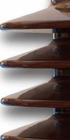
13 Porcelain and composite insulator Porcelain Insulator (Type COT) Composite Insulator (Type COTC) Brown color (RAL 8016) Gray color (ANSI gray N70) Alternate sheds (ANSI gray N70) Helicoil sheds (ANSI gray N70) D4 D4 D4 D4 All COT(C) can be equipped with silicone rubber insulators upon request without affecting dimensions except D4 Substitute for E &E Page 13 / _ _00
14 Standard Oil level indicator COT 125, COT 170 Oil level indicator COT 250 COT 1050 Ø20 Ø60 Fig. 6 Fig. 7 Test tap (2kV) Air escape screw O-ring gasket 22 6 Multiple spring contact Flat gasket Fig. 8 Fig. 9 Substitute for E &E Page 14 / _ _00
15 Options Magnetic oil level indicator (Ø95) COT 250 COT 1800 Arcing horns Type min S max mm COT S COT COT COT COT COT COT COT COT Fig. 10 Fig. 11 Voltage tap according to ANSI/IEEE (20kV) Oil sampling device Multiple spring contact Valve Fig. 12 Fig. 13 Substitute for E &E Page 15 / _ _00
16 Recommendations for lead out arrangement Embedded shield These bushings are equipped on the lower end with a cone shaped epoxy resin tube and an embedded electrode. Therefore, additional barriers or electrodes may be omitted and distance to ground is reduced External shield R1 R S Oil conditions: Mineral oil with less than 10ppm water content and dielectric strength higher than 60kV (acc. to IEC 60156) Fig. 14 Fig. 15 Draw lead insulation COT COT 1050 Ø40 Ø35,7 Cable insulation and distance to grounded parts Type Min. insulation thickness Min. distance to grounded parts S S 15 Ø80 (Um=245kV) Ø94 (Um=300kV) Fig. 16 Fig. 17 S R R1 mm COT COT COT COT COT COT COT COT COT COT 1175 to COT See spec Substitute for E &E Page 16 / _ _00
17 Removable Removable split conductor split conductor COT 125 COT 125 COT 1175 COT A 1250 A Cable bolt Cable bolt Removable split Removable conductor split conductor fixing screws 3 fixing screws Oil side end Position of standard split conductor. Others positions on request Oil side end 30 COT 125, COT 170 Ø29 Fig A 1250A A Ø40 COT 125, COT 170 Position of standard split conductor. Others positions on request Fig. 18 Ø A 1250A A Ø29 30 Ø40 Ø40 30 Ø Conductor Ø35 30 Ø40 Ø80 Ø80 Ø80 Cable Removable Ø Fig. 19 copper conductor Fig. 20 Fixed copper-conductor Fig. 21 Ø80 Conductor Ø35 Ø80 Ø40 Ø80 Cable Fig. 19 Removable copper conductor Fig. 20 Fixed copper-conductor Fig. 21 Substitute for E &E Page 17 / _ _00
18 Oil side end COT 250 COT A 1250A 1600 A 30 Ø29 8 Conductor Ø35 90 Ø35,7 Ø80 Ø80 Ø35 Ø80 Cable Fig. 22 Removable copper conductor Fig. 23 Fixed copper-conductor Fig A 3150A Ø40 Ø94 Fixed copper-conductor Ø40 Ø104 Fig. 25 Fixed copper-conductor Fig. 26 Substitute for E &E Page 18 / _ _00
19 Oil side end COT 550 COT A 1250A 1600 A Ø29 Conductor Ø35 90 Ø35,7 Ø68 Ø68 Ø35 Ø68 Cable Fig. 27 Removable copper conductor Fig. 28 Fixed copper-conductor Fig A 3150A 15 22, Ø40 Ø86 Ø114 Fixed copper-conductor Ø40 Ø160 Ø240 Fig. 30 Fixed copper-conductor with removable screwed shield Fig. 31 Substitute for E &E Page 19 / _ _00
20 Oil side end COT 1050, Um = 245 kv 1000A 1250A 1600 A Ø40 25 Ø29 90 Ø80 Conductor Ø38 Ø35 Ø119 Ø119 Ø119 Cable Fig. 32 Removable copper conductor Fig. 33 Fixed copper-conductor Fig A 3150A Ø40 Ø40 Ø95 Ø134 Fixed copper-conductor Ø180 Ø260 Fig. 35 Fixed copper-conductor with removable screwed shield Fig. 36 Substitute for E &E Page 20 / _ _00
21 Oil side end COT 1050, Um = 300 kv 1000A 1600A Ø Ø35 Ø95 Ø134 Ø95 Ø134 Cable Fig. 37 Fixed copper-conductor Fig A Ø40 Ø180 Ø260 Fixed copper-conductor with removable screwed shield Fig. 39 Substitute for E &E Page 21 / _ _00
22 Oil side end COT A 1600A Ø55 Ø110 Ø190 Cable with fixed shield Ø125 Oil side connector according to customer request Fig. 40 Fixed conductor Fig. 41 COT A 1600A Ø68 Ø Ø210 Ø330 Cable with fixed shield Ø160 Oil side connector according to customer request Fig. 42 Fixed conductor Fig. 43 Substitute for E &E Page 22 / _ _00
23 Oil side end : External shields FIXED SHIELD SHIELD WITH BAYONET SYSTEM Ø D 3 x M6 depth 15mm equidistant on a drilling diameter D Fig. 44 SCREWED SHIELD A Detail A Connection according to customer drawing Fig. 45 Fig. 46 Substitute for E &E Page 23 / _ _00

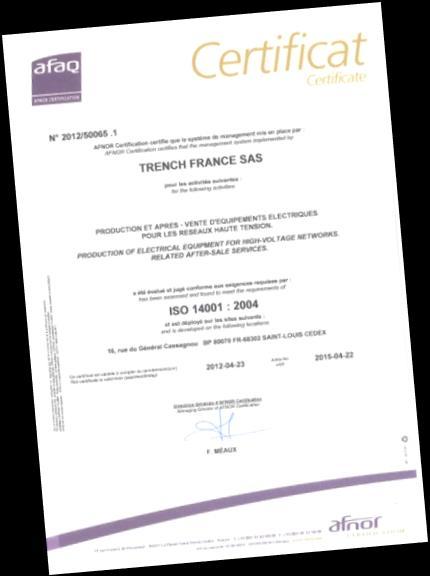
24 Product Range Bushings for Power Transformers up to 550 kv, 5000A High Current Application up to 52 kv, A Quality At Trench quality is a way of life. Trench quality assurance complies with the most stringent standards of ISO 9001 and ISO Certified by AFAQ since 1994 Transformer to SF6 connection up to 550kV Gas-insulated Switchgear (GIS) up to 800 kv, 6000A Generators up to 36 kv, A Railways Buildings, Wall up to 245 kv, 5000 A Bushings according Standard IEC Bushings according to customer s special specification Trench Limited Bushing Division 432 Monarch Avenue Ajax, Ontario Canada L1S 2G7 Phone : Fax : imprimerie de saint-louis substitute for E &E _01 Trench France SAS 16, rue du Général Cassagnou B.P F Saint-Louis Cedex France Phone : Fax : Sales-bushing.fr@trench-group.com All rights reserved. Brands and trademarks used in this document are the property of Trench Subject to change without prior notice. The information in this document contains general descriptions of the technical options which are not necessarily available in every single case. The required features must therefore be defined in each individual case when concluding the contract.

25 Bushings for metal clad installations SF6 / Oil Type SOT 123 kv to 550 kv Up to 2500 A According IEC & IEC

26 Bushings for transformer to gas insulated switchgear connections Trench OIP technology for Oil / SF6 bushings Application: Bushing Type SOT SF6 This type of bushing, suitable for direct connection between metal clad SF6-insulated switchgear and transformers, enables the integrating of power transformers to the grounded enclosure system of the switchgear. It is no longer required to join the transformers to the switchgear by means of overhead lines or cables, thus saving outdoor bushing or cable end boxes on both switchgear and transformer side. Features: Design is in line with latest requirements of IEC 1639 for gas side connection. Experience in bushing manufacture for more than 90 years. Capacitance fine graded oil-paper insulation with long experience. Computer optimized electrical field distribution. Proven high electrical withstand against transient or impulse test. Excellent long term stability due to extremely low partial discharge and power loss factor. Oil immersed part and SF6 part covered by epoxy resin tube providing high impact resistance. Tan δ and PD-values more than twice as good as requested by IEC Possibility to trace SF6 gas by means of doing DGA (dissolved gas analysis) Long term easy storage: Bushing 100% tight towards ambient humidity. Transformer Certified ISO 9001 Certified ISO Page 2 / _00

27 Oil / SF6 Bushing Design 1 2 SF6 side Shield (on request) SF6 side Terminal Terminal (Al or Cu) for connection is designed according standard IEC SF6 side end The insulator on the SF6 side is made of an epoxy resin tube. 4 Active part The active part is made of oil-impregnated wide band paper with layers of aluminum foil to control the electrical field radially and axially. Depending on the current rating, the paper and foil are wounded on either a central tube or conductor 5 Flange Mounting flange with integrated test tap and oil sampling device made of corrosion free aluminum alloy, machined to ensure an excellent seal between the bushing and the transformer or metal clad SF6 insulated switchgear. 6 Oil sampling device Test tap Test tap for through life capacitance and tan delta measurement. Oil side end The insulator on the SF6 side is made of an epoxy resin tube. Oil side terminal Terminal (Al or Cu) for connection Dimensions according customer request Oil side Shield (on request) Page 3 / _00
28 Standard: 100, 300 Highest voltage (Um) Maximum phase to earth voltage Bushing Dry Power frequency voltage withstand (AC) Transformer Power frequency voltage withstand (AC) Lightning Impulse withstand voltage (BIL) Switching Impulse withstand voltage (SIL) Rated current (Ir) CT Space L4 Mass Approx. Cantilever test load (min) Type SOT kv kv kv kv kv kv A mm kg N L L1 L2 L3 L5 L6 L7 L8 D1 D2 D3 D4 D5 D6 D7 D8 D9 D10 n1 t1 n2 t2 n3 m3 n4 m4 mm ± M ± M M ± Page 4 / _00
29 Standard: 100, 300 Highest voltage (Um) Maximum phase to earth voltage Bushing Dry Power frequency voltage withstand (AC) Transformer Power frequency voltage withstand (AC) Lightning Impulse withstand voltage (BIL) Switching Impulse withstand voltage (SIL) Rated current (Ir) CT Space L4 Mass Approx. Cantilever test load (min) kv kv kv kv kv A mm kg N L L1 L2 L3 L5 L6 L7 L8 D1 D2 D3 D4 D5 D6 D7 D8 D9 D10 n1 t1 n2 t2 n3 m3 n4 m4 mm ± M12 4 M10 Comments related to columns : 03: Bushings test voltage at 50Hz 60 sec. 08: Other extension current transformer on request 11,12: L 1 depends on L 4. The values in the table are valid for L 4= 100mm. If L 4>100mm add L 4 to L 1 and L. Page 5 / _00

30 L4 L1 L2 L3 L Dimensional Drawing SF6-Side ød4 L5 L6 ød1 Oil-Side Page 6 / _00


31 Dimensional Drawing Ø D6 Ø D5 SF6 side n3 x M 3 Ø D8 Ø D ± 0.3 L7 n2 x ø t2 Oil side Ø D3 Ø D2 L8 n1 x ø t1 n4 x M 4 Ø D9 Ø D10 Page 7 / _00


")


32 Standard G1/4 Air Outlet Flat gasket 6 Test tap (2kV) Multiple spring contact O-ring gasket 22 Oil sampling device Valve Page 8 / _00


33 On request Pressure control This system permit to control the pressure inside of the bushing Stress shield Stress shields are also available with bayonet fixing system and screwed fixing system If you need any Oil / SF6 bushing proven in operation conditions around the world, Trench has it! Page 9 / _00
34 Technical data request Mark the requested value Um 123kV 145kV 170kV 245kV 420kV 550kV Other... Up Transformer 230kV 275kV 325kV 460kV 630kV 680kV Other... BIL 550kV 650kV 750kV 1050kV 1425kV 1550kV 1675kV Other... Rated Current 1250A 1600A 2500A Other... CT Space 100mm 300mm Other... Terminals Material Aluminum Copper Other... Maximum Oil Temperature Other... Bus Duct Temperature Other Page 10 / _00
35 Notes: Page 11 / _00
36 _00 Page 12 / _00


37 Transformer High Current Bushings Type CFPT & CFCT 36kV up to 40kA IEC

38 High current bushings for transformer Features Bushing Type CFPT version Porcelain Insulator Trench RIG technology for oil-free, dry type bushings Experience: More than pieces with this insulation in service for more than 30 years (Generator Bushings with Ir max. 50kA) Trench RIG technology (Resin Impregnated FiberGlass) The active part consists of a solid core, made of fiber glass and inserted concentric layers for the electrical field distribution. The active part is impregnated under vacuum with a special epoxy resin. Advantages and benefits Bushing Type CFCT version Composite Insulator Insulation (class F, 155 C) according IEC Partial discharge <10pC at Um Low dissipation factor (tg ) <0,005 No paper for insulation; limited sensibility to humidity Highest mechanical performance today Higher performance due to cooling system with transformer oil No additional filling between porcelain and active part Tightness of the bushing is made by means of O-rings No over pressure in the bushing possible Easy Interchangeability with all existing designs Possibility to offer the whole package for GSU transformers Available with porcelain or composite insulator on air side with same dimensions Bushing can be vertically or horizontally mounted Standard creepage distance: 31mm/kV Page 2 / _ _01
 4. Active part in resin impregnated fiber glass 5. Insulator porcelain or composite 6. Flange in aluminum 7. Air escape screw 8.")
39 High current bushings for transformer Design Top terminal in aluminum or copper (silver-plated) 2. Conductor in aluminum in standard or copper on request 3. Bottom terminal in aluminum or copper (silver-plated) 4. Active part in resin impregnated fiber glass 5. Insulator porcelain or composite 6. Flange in aluminum 7. Air escape screw 8. Test tap Standards Trench RIG high current bushings are specified and tested according to the latest IEC and IEEE C Current rating The CFPT and CFCT bushings are designed to connect an oil filled transformer winding to a generator bus in a duct. The bushing current rating is guaranteed for the following environmental conditions: o Transformer oil temperature = 90 C o Maximum, hot spot, bushing conductor temperature = 135 C o Maximum ambient air temperature in bus duct = 70 C CFPT and CFCT bushings will operate properly regardless of the surrounding air temperature inside the bus duct Rated current can be increased when used without a bus duct. Maintenance free Maintenance and inspection free The bushings are equipped with a test tap (see page 7 picture 5) on the flange. This enables the dielectric dissipation factor (tg ) and the capacitance of the bushing to be measured. Page 3 / _ _01
40 Type CFPT & CFCT 36kV Highest voltage (Um) Maximum phase to earth voltage Bushing Dry Power frequency voltage withstand (AC) Transformer Power frequency voltage withstand (AC) Lightning Impulse withstand voltage (BIL) Rated current (Ir) CT Space L4 AD Arcing distance (min.) Standard creepage distance 31mm/kV Mass Approx. Cantilever test load (min) Number of upper connection pads Number of lower connection pads Top terminal Bottom terminal See connection page L L1 L2 L4 D1 D2 D3 D4 D5 øt n e kv kv kv kv kv A mm mm mm kg N mm mm xØ18 4xØ18 page xØ18 4xØ18 page xØ18 6xØ18 page xØ18 8xØ18 page xØ18 12xØ18 page xØ18 16xØ18 page 11 Standard: 0, 300 Comments related to columns : 03: Bushings test voltage at 50Hz 60 sec. 07: Other extension current transformer on request 08,09: Brown glazed porcelain, Gray color on request 09: 31mm/kV in standard 12,13: L1 depends on L4. The values in the table are valid for L4= 0mm. If L4>0mm add L4 to L1 and L. Page 4 / _ _01


41 Dimensional Drawing D4 D5 L2 L1 L4 L D1 n x øt 3x45 e D2 D3 Page 5 / _ _01

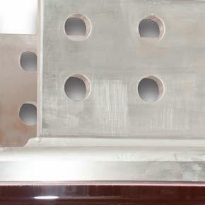
42 Standard Aluminum Connection 7800A 150 on pads 55 Air side 4 connections pads Thickness 25mm 2 x ø Oil side x ø Page 6 / _ _01

43 Standard Aluminum Connection 12000A 235 on pads 55 Air side 6 connections pads Thickness 25mm 2 x ø Oil side x ø18 Page 7 / _ _01

44 Standard Aluminum Connection 16000A 335 on pads 55 Air side 10 connections pads Thickness 25mm 2 x ø Oil side x ø18 Page 8 / _ _01

45 Standard Aluminum Connection 20000A 460 on pads Air side 14 connections pads Thickness 25mm x ø x ø18 Oil side Page 9 / _ _01

46 Standard Aluminum Connection 25000A Air side 16 connections pads Thickness 25mm 560 on pads x ø18 2 x ø18 Oil side Page 10 / _ _01

47 Standard Aluminum Connection 31500A Air side 22 connections pads Thickness 25mm 670 on pads 2 x ø x ø Oil side Page 11 / _ _01

48 On Request Every connection and interchangeability configuration can be done Page 12 / _ _01
49 G1/4 Air Outlet Test Tap Springs Lock System Page 13 / _ _01
50 Technical data request Mark the requested value Um 24kV 36kV 52kV Other... Up Transfo 50kV 70kV 95kV Other... BIL 125kV 170kV 250kV Other... Rated Current 7800A 12000A 16000A 20000A 25000A 31500A Other... CT Space 0mm 300mm Other... Terminals Material Aluminum Copper Other... Maximum Oil Temperature Other... Bus Duct Other... Mounting Vertical Horizontal Other Page 14 / _ _01
51 Notes: Page 15 / _ _01
52 Product Range Bushings for Power Transformers up to 550 kv, 5000A High Current Application up to 52 kv, 40kA Quality At Trench quality is a way of life. Trench quality assurance complies with the most stringent standards of ISO 9001 and ISO Certified by AFAQ since 1994 Transformer to SF6 connection up to 550kV Gas-insulated Switchgear (GIS) up to 800 kv, 6000A Generators up to 36 kv, 50kA Railways Buildings, Wall up to 245 kv, 5000A Bushings according Standard IEC Bushings according to customer s special specification imprimerie de saint-louis troendlé bieler _01 Trench France SAS 16, rue du Général Cassagnou B.P F Saint-Louis Cedex France Phone : Fax : Sales-bushing.fr@trench-group.com All rights reserved. Brands and trademarks used in this document are the property of Trench Subject to change without prior notice. The information in this document contains general descriptions of the technical options which are not necessarily available in every single case. The required features must therefore be defined in each individual case when concluding the contract.


53 Generator High Voltage Bushings up to 36 kv up to 50kA according to all standards or customer specification
 The active part consists of a solid core, made of fiberglass reinforced epoxy resin, impregnated under vacuum.")
54 High voltage bushings for Generator Application: Generator bushings are used for leading the current induced in the stator-windings through the pressurized, hydrogen-gas tight, earthed generator housing. Trench RIG technology (Resin Impregnated FiberGlass) The active part consists of a solid core, made of fiberglass reinforced epoxy resin, impregnated under vacuum. - Low partial discharge and power loss factor - Excellent behavior in temperature - High resistance to mechanical stress Features: Experience in bushing manufacture for more than 40 years. More than Generator bushings in service. Easy interchangeability with old bushing existing designs, dimensions may be chosen in order to secure direct interfacing with all generator designs. Excellent long term stability due to extremely low partial discharge and power loss factor (PD 10 pc at 1.05 Ur / 3 ; Tanδ at 1.05 Ur / 3) Epoxy resin tube providing high impact resistance and excellent behavior in temperature (Class F = 155 C) Paint cover on the active part : no real utility of porcelain mounting (porcelain on request) Flange made of aluminum (non magnetic steel on request) Very good mechanical static and vibrations withstand. Proven high electrical withstand against impulse test. Tightness is guaranteed by O-rings : no leakage due to pressure in the bushing. Fast and easy maintenance of our bushings during refurbishment of the generator, also after 20 years of service. Certified ISO 9001 Certified ISO Page 2 / _00
55 High voltage bushings for Generator 1 Air side connection Design Copper with silver plated connecting area Cover (when porcelain) Tightening nut O-ring Ensure the tightness between in- and out-side of the bushing. 5 6 Porcelain insulator (on request) Flange Mounting flange made of corrosion-free aluminum alloy (or non-magnetic stainless steel on request). Glued-shrunk on the insulation tube and machined to ensure an excellent seal between the bushing and the generator housing. 7 O-ring Redundant O-ring to ensure tighness between flange and tube i.e. gas side and air side of the bushing 8 Active part / Insulation tube Active part made out of fiberglass reinforced epoxy resin with one earthed layer foil to control the electrical field radially and axially. Temperature class F (155 C) 9 Copper conductor Copper conductor made out of oxygen free copper (acc. to EN 13600/13601) 10 Guiding/Centering ring The centering ring maintains the insulation tube centered with the copper conductor and allows coaxial thermal expansion without stress. 11 Gas side connection Copper with silver plated connecting area Page 3 / _00
56 High voltage bushings for Generator Design The main conductor (9) is made out of oxygen free copper (acc. to EN 1600/13601) with silver plated connecting areas. The supporting insulation tube (8) is a vacuum impregnated, glassfiber reinforced epoxy resin (temperature class F : 155 C). Both parts are assembled at the air side through a tightening cone including an O-ring gasket (4). A tightening nut (3) ensures a gastight immobilization of the whole assembly. The space between the conductor and the insulating tube is filled with the hydrogen gas of the generator. The gas pressure in the bushing increases the pressure on the tightness gasket (4). The insulation tube is supported at the gas-end by a guiding disc (10) which allows the current lead to expand in both directions without stressing the gasketing area (4). The active part is not in contact with the conductor and will age very slowly. The fixing flange (6) is made out of antimagnetic metal. It is glued-shrunk onto the insulation tube. An O-ring (7) ensures the tightness between both parts. Depending on the voltage, the insulating tube is electrically graded in order to grant a homogeneous field distribution. The material is, up to a large extend, impervious to humidity and needs no additional protection while used in dry or moderately humid places. For unfavorable climatic conditions or heavily polluted environment, the insulation tube may be protected by a glazed and grooved porcelain (5) at the air side. This porcelain is not pressure-stressed by the hydrogen gas, and in case of breaking, it can be interchanged without removing the bushing from the generator. Standards TRENCH Generator Bushings are specified and tested according to latest IEC 60137, DIN 48124, ANSI/IEEE or customer specification. The dimensions depend on the specified rated and test values. The dimensions may be chosen in order to secure direct interfacing with all generator designs. The current load is depending on cooling medium temperature, pressure and flow, as well as on connection design, to be defined between the buyer and the manufacturer. Designation Example : V R P H 25 / V Insulator body of glassfiber R with tubular conductor S with profile conductor P if with Porcelain H Gastight (H2, etc) Ur (kv) Nominal voltage Up (kv) Test voltage 50/60Hz, 1min I (ka) Rated current F Liquid cooled Page 4 / _00
57 Natural cooled up to 19 ka Service and cooling conditions as per DIN 48124, part.1 in vertical to horizontal service position. Connecting areas silver plated 5µm ; Rated voltage up to 36 kv. Examples : Standard IEC DIN Nominal Voltage (kv) Phase to earth Voltage (kv) Test Voltage (kv) 50/60 Hz, 1 min Impulse Voltage (kv) 1.2/50µs Designation Rated Voltage kv Test voltage 50/60 Hz, 1min. kv Impulse voltage 1,2/50 µs kv Rated Current ka Standard VSH 17.5/45 N100x185 17, DIN VSH 17.5/45 N120x185 17, DIN VSH 17.5/ , IEC VSPH 24/ IEC VRH 19/59 N140x IEC VRH 20/ IEC VRH 21.5/57 N100x IEC / DIN VRPH 25/ IEC VSH 17.5/45 N100x185 Page 5 / _00
58 Gas cooled up to 35 ka Current load depending on the coolant gas temperature and speed, as well as on the connection design, to be defined between the buyer and the manufacturer Connecting areas silver plated 5µm ; Rated voltage up to 36 kv. Examples : Standard IEC Nominal Voltage (kv) Phase to earth Voltage (kv) Test Voltage (kv) 50/60 Hz, 1 min Impulse Voltage (kv) 1.2/50µs DIN IEEE Designation Rated Voltage kv Test voltage 50/60 Hz, 1min. kv Impulse voltage 1,2/50 µs kv Rated Current ka Standard VRH 16/ IEC VRH 17.5/45 N120x IEC VRH 18.8/ , DIN VRH 19.1 G -110x185 19, DIN VRH 19.1/ , IEC VRPH 21/ IEC VRH 23.3 GC120x IEC / DIN VRPH 25/ IEC VRH 26/ IEC / DIN VRPH 27/ IEC VRPH 25/ Page 6 / _00
59 Liquid cooled - up to 50 ka Current load depending on the temperature, flow rate and guidance of the coolant, as well as on the connection design, to be defined between the buyer and the manufacturer Connecting areas silver plated 5µm ; Rated voltage up to 36 kv. Standard Nominal Voltage (kv) Phase to earth Voltage (kv) Test Voltage (kv) 50/60 Hz, 1 min Impulse Voltage (kv) 1.2/50µs IEC DIN IEEE Examples : Designation Rated Voltage kv Test voltage 50/60 Hz, 1min. kv Impulse voltage 1,2/50 µs kv Rated Current ka Standard VFH 23.1 LC-120Mx IEC VFH 24/ IEC VFH 24.5 LC-120Mx IEC / DIN VFPH 25/ IEC60137 VFH 27/82.5 LC-150Mx DIN VFH 27.8 LC-120Mx VFH 30/75 LC120Mx IEC / DIN IEC / DIN VFPH 30/ IEC VFH 36/ IEC VFH 36/ IEC VFH 36/ Page 7 / _00
60 Product Range Bushings for Power Transformers up to 550 kv, 5000A High Current Application up to 52 kv, 40kA Quality At Trench quality is a way of life. Trench quality assurance complies with the most stringent standards of ISO 9001 and ISO Certified by AFAQ since 1994 Transformer to SF6 connection up to 550kV Gas-insulated Switchgear (GIS) up to 800 kv, 6000A Generators up to 36 kv, 50kA Railways Buildings, Wall up to 245 kv, 5000A Bushings according Standard IEC Bushings according to customer s special specification imprimerie de saint-louis _00 Trench France SAS 16, rue du Général Cassagnou B.P F Saint-Louis Cedex France Phone : Fax : Sales-bushing.fr@trench-group.com All rights reserved. Brands and trademarks used in this document are the property of Trench Subject to change without prior notice. The information in this document contains general descriptions of the technical options which are not necessarily available in every single case. The required features must therefore be defined in each individual case when concluding the contract.


61 Oil Impregnated Paper Transformer Bushings type COT with Composite Insulator More than 20 years Experience Outstanding performance for heavy polluted application Excellent Resistance to vandalism Maintenance free Particularly suitable in seismic area Lower Weight versus porcelain insulator
62 Composite Insulator Composite insulators are available for our range of products COT from 24 to 550kV as well as for High Current bushings CFPT (Please refer to our catalogues references E322.81, E322.90) Both types of bushings have the same dimensions either if they are with a porcelain or composite insulator. They will be fully interchangeable with existing units. Basic Structure of Hollow Composite Insulators Trench in co-operation with its suppliers has developed a special high quality silicone for its bushing composite insulators. Tube in Fiberglass impregnated with epoxy resin Silicone Rubber sheds Benefits from Composite Insulators Safety Flashover resistant by the suppression of leakage currents Explosion proof, no collateral damage Resistant against vandalism Low risk of damages due to handling failures Maintenance free Outstanding performance in high level pollution environment. The particular characteristics of the composite insulator need seldom cleaning operations even if running in severe conditions.


63 Easy to use Composite insulators have a significant lower weight Easier handling and installation Damaged sheds can be repaired on-site Hydrophobicity The surface of the high voltage composite insulator is hydrophobic, the leakage currents as well as the surface discharge activities are significantly reduced. Lifetime Trench was one of the first manufacturers to use composite materials for high voltage insulators. Now, composite insulator is a well-established product in the high voltage industry world-wide. Trench has years of experience with electrical and mechanical design, material selection, production and testing. Having installed more than 10,000 units we have experience in different climatic zones and at all high voltage levels. No deterioration ageing of our composite insulators has been reported. With this background, Trench is in a position to guarantee long life for all its composite insulators. Earthquake resistant Particularly suitable in regions where severe earthquakes may be expected. From a dynamic or seismic stand point, composite performs much better in earthquake than porcelain This has been proved by the most critical test: 1.0G, 10 Cycles Sine-Beat Test For 500 kv, 345 kv and 230 kv The Fiberglass Tube and Composite housing provide an unique combination of lower weight and high strength.
64 Product Range Quality Bushings for At Trench quality is a way of life. Trench quality assurance complies with the most stringent standard of ISO Power Transformers up to 550 kv, 3150A High Current Application up to 52 kv, A Transformer to SF6 connection up to 550kV Generators up to 36 kv,50000 A Railways Buildings, Wall up to 245 kv, 5000 A Bushings according Standard IEC Bushings according to customer s special specification Trench Switzerland-France 16, rue du Général Cassagnou B.P F Saint-Louis Cedex France Phone : Fax : imprimerie de saint-louis troendlé bieler Subject to change without notice Sales-bushing.fr@trench-group.com Certified by AFAQ since 1994


65 WALL BUSHING Type CPWP 24 to 123kV Outdoor/Outdoor service up to 2500A IEC GB 1 / 4 September 2004 revision 00
66 Technical Data Wall bushings Type CPWP 24 to 123kV Outdoor/Outdoor N. Rated Voltage Rated phase to earth voltage Test Voltage 60 sec. Impulse Voltage 1,2/50 µs Rated Current Material of connection Wall (L4) AD Arcing distance (min.) Standard creepage distance (min.) Mass Approx. Cantilever test load (min.) L L1 L2 D6 x L6 D1 D2 D3 D4 D5 t e kv kv kv kv A mm mm mm kg N mm mm mm mm mm mm mm mm mm mm mm Aluminium x Aluminium x Copper x Copper x Aluminium x Aluminium x Copper x Copper x Standard: 300, Aluminium x Aluminium x Copper x Aluminium x , Aluminium x Copper x Aluminium x Aluminium x Copper x Aluminium x Aluminium x Copper x Application Wall bushings of the type CPWP are used to transfer the electrical voltage through a wall on outdoor side Description The insulating body of bakelised paper is wound on a solid conductor. To achieve uniform voltage distribution in radial and axial direction, a number of conducting layers are wound into this body in such a manner that a series of coaxial capacitors is obtained between conductor and mounting flange. The flange, made of aluminium is glued on the insulating body. The inner capacitor layer is connected to the conductor and the exterior one to the flange by a contact screw. The service position of this type of wall bushing is horizontal. Comments related to columms L2, L3 and Mass The values and mass are valid for a wall (L4) of 300mm GB 2 / 4 September 2004 revision 00

67 Technical Data Wall bushings Type CPWP 24 to 123kV Outdoor/Outdoor GB 3 / 4 September 2004 revision 00
68 Product Range Quality Bushings for - Power Transformers up to 765 kv, 3150A (>245 kv see separate brochure) High Current Application up to 36 kv, A Transformer to SF6 connection up to 550kV - Gas-insulated Switchgear (GIS) up to 800 kv, 6000A - Generators up to 36 kv,45000 A - Railways - Buildings up to 245 kv, 3000 A Bushings according standards as: IEC Bushings according to customer's special specification At Trench quality is a way of life. Trench quality assurance complies with the most stringent standard of ISO Certified by AFAQ since 1994 Trench Austria Gmbh Paschinger Srasse 49 Posfach 13 A-4060 Linz-Leonding Austria Phone: Fax: Trench Brasil Ltda Via Expressa de Contagem, 2685 Contagem, Minas Gerais CEP Brazil Phone: Fax: Trench China MWB (Shanghai) Co.,Ltd No.3658 Jiangcheng Road Minhang, Shanghai, Peoples Republic of China Phone: Fax: Trench Fushun Dong Er Dao, Shuncheng District, Fushung, Liaoning Province, Peoples Republic of China Phone: Fax: Trench Limited Bushing Division 432 Monarch Avenue Ajax, Ontario Canada L1S 2G7 Phone: Fax: Trench Limited Coil Product Division 71 Maybrook Drive Scarborough, Ontario Canada M1V 4B6 Phone: Fax: Trench Limited Instrument Transformer Division 390Midwest Road Scarborough, Ontario Canada M1P 3B5 Phone: Fax: Trench France S.A. 16, Rue du Général Cassagnou B.P.70 F Saint Louis, Cedex France Phone: Fax: Trench Germany GmbH Nürnberg Strasse 199 D Bamberg Germany Phone: Fax: Trench Schwitzerland Lehenmattstrasse 353 CH-4028 Basel Schwitzerland Phone: Fax: Trench (UK) Limited South Drive Hebburn Tyne & Wear NE 31 1 UW Phone: Fax: GB 4 / 4 September 2004 revision 00
69 GUIDE LINE FOR WALL BUSHINGS Requested Information Trench choice if not specified: Customer Request Application: indoor - indoor outdoor - indoor outdoor - outdoor Standard: IEC IEC Rated Voltage: 50 Hz 1 min test voltage 1,2/50µs BIL Rated Current: Thermal Short-Circuit current Dynamical Short Circuit current peak Conductor/connection: connection dimension (D6 x L6) Wall thickness (L4) kv kv A ka. s ka Copper or Aluminium x Ir during 3 sec 2,55 x I th Elevation above sea level: M 1000 m Outdoor Pollution Class (25mm/kV, 31mm/kV or special) Indoor conditions: Standard maximum annual average humidity On request maximum annual average humidity Clean room mm/kv 65% 80% 25 mm/kv 65% Clean room

70 WALL BUSHING Type CPW 24 to 123kV Indoor/Outdoor service up to 2500A IEC GB 1 / 4 September 2004 revision 00
71 Technical Data Wall bushings Type CPW 24 to 123kV Indoor/Outdoor N. Rated Voltage Rated phase to earth voltage Test Voltage 60 sec. Impulse Voltage 1,2/50 µs Rated Current Material of connection Wall (L4) AD Arcing distance (min.) Standard creepage distance (min.) Mass Approx. Cantilever test load (min.) L L1 L2 D6 x L6 D1 D2 D3 D4 D5 t e kv kv kv kv A mm mm mm kg N mm mm mm mm mm mm mm mm mm mm mm Aluminium x Aluminium x Copper x Copper x Aluminium x Aluminium x Copper x Copper x Standard: 300, Aluminium x Aluminium x Copper x Aluminium x , Aluminium x Copper x Aluminium x Aluminium x Copper x Aluminium x Aluminium x Copper x Application Wall bushings of the type CPW are used to transfer the electrical voltage through a wall or a room closing with moderate humidity indoor side - standard maximum annual average of 65% humidity (without water condensation) indoor side. - on request maximum annual average of 80% humidity with a special painting (without water condensation) indoor side. Description The insulating body of bakelised paper is wound on a solid conductor. To achieve uniform voltage distribution in radial and axial direction, a number of conducting layers are wound into this body in such a manner that a series of coaxial capacitors is obtained between conductor and mounting flange. The flange, made of aluminium is glued on the insulating body. The inner capacitor layer is connected to the conductor and the exterior one to the flange by a contact screw. The service position of this type of wall bushing can be vertical or horizontal. Comments related to columms L2, L3 and Mass The values and mass are valid for a wall (L4) of 300mm GB 2 / 4 September 2004 revision 00

72 Technical Data Wall bushings Type CPW 24 to 123kV Indoor/Outdoor GB 3 / 4 September 2004 revision 00
73 Product Range Quality Bushings for - Power Transformers up to 765 kv, 3150A (>245 kv see separate brochure) High Current Application up to 36 kv, A Transformer to SF6 connection up to 550kV - Gas-insulated Switchgear (GIS) up to 800 kv, 6000A - Generators up to 36 kv,45000 A - Railways - Buildings up to 245 kv, 3000 A Bushings according standards as: IEC Bushings according to customer's special specification At Trench quality is a way of life. Trench quality assurance complies with the most stringent standard of ISO Certified by AFAQ since 1994 Trench Austria Gmbh Paschinger Srasse 49 Posfach 13 A-4060 Linz-Leonding Austria Phone: Fax: Trench Brasil Ltda Via Expressa de Contagem, 2685 Contagem, Minas Gerais CEP Brazil Phone: Fax: Trench China MWB (Shanghai) Co.,Ltd No.3658 Jiangcheng Road Minhang, Shanghai, Peoples Republic of China Phone: Fax: Trench Fushun Dong Er Dao, Shuncheng District, Fushung, Liaoning Province, Peoples Republic of China Phone: Fax: Trench Limited Bushing Division 432 Monarch Avenue Ajax, Ontario Canada L1S 2G7 Phone: Fax: Trench Limited Coil Product Division 71 Maybrook Drive Scarborough, Ontario Canada M1V 4B6 Phone: Fax: Trench Limited Instrument Transformer Division 390Midwest Road Scarborough, Ontario Canada M1P 3B5 Phone: Fax: Trench France S.A. 16, Rue du Général Cassagnou B.P.70 F Saint Louis, Cedex France Phone: Fax: Trench Germany GmbH Nürnberg Strasse 199 D Bamberg Germany Phone: Fax: Trench Schwitzerland Lehenmattstrasse 353 CH-4028 Basel Schwitzerland Phone: Fax: Trench (UK) Limited South Drive Hebburn Tyne & Wear NE 31 1 UW Phone: Fax: GB 4 / 4 September 2004 revision 00
 Wall thickness")
74 GUIDE LINE FOR WALL BUSHINGS Requested Information Trench choice if not specified: Customer Request Application: indoor - indoor outdoor - indoor outdoor - outdoor Standard: IEC IEC Rated Voltage: 50 Hz 1 min test voltage 1,2/50µs BIL Rated Current: Thermal Short-Circuit current Dynamical Short Circuit current peak Conductor/connection: connection dimension (D6 x L6) Wall thickness (L4) kv kv A ka. s ka Copper or Aluminium x Ir during 3 sec 2,55 x I th Elevation above sea level: M 1000 m Outdoor Pollution Class (25mm/kV, 31mm/kV or special) Indoor conditions: Standard maximum annual average humidity On request maximum annual average humidity Clean room mm/kv 65% 80% 25 mm/kv 65% Clean room
OIP Transformer Outdoor Bushings Type COT(C) 125 COT (C) kV to 550kV up to 5000A IEC
 125 COT (C) kV to 550kV up to 5000A IEC") OIP Transformer Outdoor Bushings Type COT(C) 125 COT (C) 1800 24kV to 550kV up to 5000A IEC 60137-2008 Features If you need any transformer bushing proven in operation conditions around the world, Trench
OIP Transformer Outdoor Bushings Type COT(C) 125 COT (C) 1800 24kV to 550kV up to 5000A IEC 60137-2008 Features If you need any transformer bushing proven in operation conditions around the world, Trench
Transformer High Current Bushings Type CFPT & CFCT 36kV up to 40kA IEC
 Transformer High Current Bushings Type CFPT & CFCT 36kV up to 40kA IEC 60137-2008 High current bushings for transformer Features Bushing Type CFPT version Porcelain Insulator Trench RIG technology for
Transformer Bushings Type COT COT kv to 245 kv up to 3150 A IEC 137
 Transformer Bushings Type COT 5... COT 050 4 kv to 45 kv up to A IEC 37 Features If you need any transformer bushing proven in operation conditions around the world, Trench has it! experience in bushing
PNO Condenser Bushings from 52 kv to 420 kv Oil-to-air - Oil-Impregnated Paper
 GE Grid Solutions PNO Condenser Bushings from 52 kv to 420 kv Oil-to-air - Oil-Impregnated Paper PNO bushings are capacitance graded bushings with an oil impregnated paper core. PNO bushings are conform
1ZSE EN, REV. 7. Oil SF 6. bushings type GOEK Technical guide
 1ZSE 2750-106 EN, REV. 7 Oil SF 6 bushings type GOEK Technical guide Original instruction The information provided in this document is intended to be general and does not cover all possible applications.
Transformer bushings, type GOH. Technical guide
 Transformer bushings, type GOH Technical guide This Technical Guide has been produced to allow transformer manufacturers, and their designers and engineers, access to all the technical information required
OTAA Oil Impregnated Paper (OIP) Bushing for IEEE/ANSI Market
 Bushing for IEEE/ANSI Market") OTAA Oil Impregnated Paper (OIP) Bushing for IEEE/ANSI Market OTAA The OTAA is the next generation of Oil Impregnated Paper condenser bushing manufactured to IEEE C57.19.01 from 25 kv to 500 kv system
OTAA Oil Impregnated Paper (OIP) Bushing for IEEE/ANSI Market OTAA The OTAA is the next generation of Oil Impregnated Paper condenser bushing manufactured to IEEE C57.19.01 from 25 kv to 500 kv system
Bushings for High Voltage AC Applications
 Bushings for High Voltage AC Applications Selection guide 1ZSE 2750-100 en, Rev. 3, 2006-03-15 During selection of for high voltage applications several important factors have to be considered to ensure
1ZSE EN, REV. 4. Wall bushings type GSA-AA Technical guide
 1ZSE 2750-112 EN, REV. 4 Wall bushings type GSA-AA Technical guide Original instruction The information provided in this document is intended to be general and does not cover all possible applications.
1ZSC AAA EN, REV. 7. Transformer bushings type GSBK Technical guide
 1ZSC563-AAA EN, REV. 7 Transformer bushings type GSBK Technical guide Original instruction The information provided in this document is intended to be general and does not cover all possible applications.
1ZSC AAA en, Rev. 6. Resin impregnated paper bushing, oil to SF 6., type GSBK Technical guide
 1ZSC563-AAA en, Rev. 6 Resin impregnated paper bushing, oil to SF 6, type GSBK Technical guide Original instruction The information provided in this document is intended to be general and does not cover
Resin Impregnated Paper Bushing, Oil to Air, Type GSB Technical guide
 1ZSC000563-AAC en, Rev. 2 Resin Impregnated Paper Bushing, Oil to Air, Type GSB Technical guide This Technical Guide has been produced to allow transformer manufacturers, and their designers and engineers,
1ZSE en, Rev. 7. Transformer bushings, type GOB Technical guide
 1ZSE 2750-102 en, Rev. 7 Transformer bushings, type GOB Technical guide This Technical Guide has been produced to allow transformer manufacturers, and their designers and engineers, access to all the technical
1ZSE en, Rev. 3. Wall bushings, type GSA-AA Technical guide
 1ZSE 2750-112 en, Rev. 3 Wall bushings, type GSA-AA Technical guide Original instruction The information provided in this document is intended to be general and does not cover all possible applications.
Resin Impregnated Paper Bushing, Oil to SF 6. , Type GSBK
 1ZSC563-AAA en, Rev. 2 Resin Impregnated Paper Bushing, Oil to SF 6, Type GSBK Technical guide This Technical Guide has been produced to allow transformer manufacturers, and their designers and engineers,
1ZSE en, Rev. 9. Transformer bushings, type GOB Technical guide
 1ZSE 2750-102 en, Rev. 9 Transformer bushings, type GOB Technical guide Original instruction The information provided in this document is intended to be general and does not cover all possible applications.
Micafil transformer oil-sf 6 bushings GARIP / RTKG kv. Power and productivity for a better world TM ABB
 Micafil transformer oil-sf 6 bushings GARIP / RTKG 72.5 55 kv Power and productivity for a better world TM ABB Design and accessories The design of the main RIP insulating body includes a solid, non-removable
ACCESSORIES FOR LPOF, HPPT AND XLPE HIGH VOLTAGE CABLE SYSTEMS PRODUCT CATALOGUE
 ACCESSORIES FOR LPOF, HPPT AND XLPE HIGH VOLTAGE CABLE SYSTEMS PRODUCT CATALOGUE hvgrid-tech designs and manufactures high voltage cable accessories for all types of cable systems, ranging from 69 kv to
Product presentation CPT tech Jason Evershed, ABB Transformer Components, May 21st New RIS transformer bushings The paper-free solution
 Product presentation CPT tech Jason Evershed, ABB Transformer Components, May 21st 2014 New RIS transformer bushings The paper-free solution Transformer condenser bushings Why a new technology? To preserve
PABS. AIR-TO-SF 6 - Gas-insulated bushing IEC STANDARDS ANSI STANDARDS AN ALSTOM COMPANY
 PABS Air-to-SF 6 Bushings 7.5-800 kv BUSHINGS AIR-TO-SF 6 - Gas-insulated bushing IEC STANDARDS 7 - ANSI STANDARDS AN ALSTOM COMPANY PABS bushings are gas-insulated types that meet IEC 7, ANSI/IEEE or
MICAFIL RIP Transformer Bushings AirRIP / RTKF kv
 INSULATION AND COMPONENTS MICAFIL RIP Transformer Bushings AirRIP / RTKF kv MICAFIL AirRIP bushings offer an extended service life combined with enhanced reliability and safety to ensure the maximum availability
DM Condenser bushings, kV DURESCA
 DM Condenser bushings, 36 DURESCA Through wall bushings for indoor and outdoor applications, Resin Impregnated Paper IEC 601378 and IEEE C57.19.01.004 DURESCA Wall bushings Swiss quality combined with
OTCF. Grid Solutions. Capacitor Voltage Transformers 72.5 kv to 800 kv. Quality Product Design. Seismic Withstand Capability.
 GE Grid Solutions OTCF Capacitor Voltage Transformers 72.5 kv to 800 kv In high and extra high voltage transmission systems, capacitor voltage transformers (CVTs) are used to provide potential outputs
Condenser Bushings. OIL-TO-AIR - Oil-Impregnated Paper ANSI STANDARDS IEEE C AND IEEE C AN ALSTOM COMPANY
 PAO Condenser Bushings - kv BUSHINGS OI-TO-AIR - Oil-Impregnated Paper ANSI STANDARDS IEEE C.9.0-000 AND IEEE C.9.0-99 AN ASTOM COMPANY PAO bushings are capacitance-graded bushings with an oil-impregnated
Transformer bushings, type GSA-OA Technical guide
 Transformer bushings, type GSA-OA Technical guide ZSE 2750- en, Rev. 5, 2005-05-5 This Technical Guide has been produced to allow transformer manufacturers, and their designers and engineers, access to
Installation Manual Bushings, IEEE/ANSI Standard
 Installation Manual Bushings, IEEE/ANSI Standard Type COTA 150.2050 for Transformers Type COBA for OCB Bushing Replacement E 8322.72 2007 Contents Page 1. Introduction 3 2. Scope 3 3. Construction 3-5
35-kV Thru-Bushings F Series (bolt-in) for Air-Insulated to Air-Insulated Service 200 Amp, 600 Amp, 900 Amp and 1250 Amp
 for Air-Insulated to Air-Insulated Service 200 Amp, 600 Amp, 900 Amp and 1250 Amp") Page 1 2018 Equipment Connection Bus Bar, or Grounded Metal Equipment Plate F Series Mounting Holes ELRIM Cycloaliphatic Epoxy Provides: Nontracking, self-scouring, nonweathering performance Superior dielectric
Page 1 2018 Equipment Connection Bus Bar, or Grounded Metal Equipment Plate F Series Mounting Holes ELRIM Cycloaliphatic Epoxy Provides: Nontracking, self-scouring, nonweathering performance Superior dielectric
1ZSE en, Rev. 9. Transformer bushings, type GSA-OA Technical guide
 1ZSE 2750-111 en, Rev. 9 Transformer bushings, type GSA-OA Technical guide Original instruction The information provided in this document is intended to be general and does not cover all possible applications.
ABB PTTR SPAIN. Zaragoza. The product: Cast coil transformers
 ABB PTTR SPAIN Zaragoza. The product: Cast coil transformers ABB BA Transformers - 1-5/7/2007 Dry Type Vacuum Cast Coil Transformer INTRODUCTION ABB BA Transformers - 2 - Product Portfolio II Dry Type
Bus bar Bushings up to 1.1kV and from 1.6kA to 4kA for Liquid Filled Transformers:
 4 (Four) Pole Monoblock: Bus bar Bushings up to 1.1kV and from 1.6kA to 4kA for Liquid Filled Transformers: Designed and manufactured in accordance with EN 50336:2002 and BS 2562: 1979 1 Introduction:
25-kV Apparatus Bushings B Series (bolt-in) for Elbow to Air-Insulated Service 200 Amp, 600 Amp, 900 Amp and 1250 Amp
 for Elbow to Air-Insulated Service 200 Amp, 600 Amp, 900 Amp and 1250 Amp") Page 1 2018 Grounded Metal Equipment Plate Equipment Connection Bus Bar or Other Component 15 kv or 25 kv Separable Insulated Connector (elbow) Equipment Connection Power Cable Power Cable ELRIM Cycloaliphatic
Page 1 2018 Grounded Metal Equipment Plate Equipment Connection Bus Bar or Other Component 15 kv or 25 kv Separable Insulated Connector (elbow) Equipment Connection Power Cable Power Cable ELRIM Cycloaliphatic
15 kv and 25 kv Thru-Bushings
 Page 1 2001 ELRIM Cycloaliphatic Epoxy Provides: Nontracking, self-scouring, nonweathering performance Superior dielectric strength, dielectric loss and power factor Choice of shapes allows design innovation
BUSHINGS: GENERAL INFORMATION
 BUSHINGS: GENERAL INFORMATION 1.0 Electrical characteristics (Ir = rated current; Ur = rated voltage) 1.1Standard insulation levels Rated voltage Ur kv (r.m.s.) 1 3,6 12 24 36 52 One minute power frequency
35-kV 200-kV BIL Apparatus Bushings B Series (bolt-in) for Elbow to Air-Insulated Service 200 Amp, 600 Amp, 900 Amp and 1250 Amp
 for Elbow to Air-Insulated Service 200 Amp, 600 Amp, 900 Amp and 1250 Amp") Page 1 2018 Grounded Metal Equipment Plate Equipment Connection 35 kv Separable Insulated Connector (elbow) Bus Bar or Other Component Grounded Metal Equipment Plate Equipment Connection Bus Bar or Other
Page 1 2018 Grounded Metal Equipment Plate Equipment Connection 35 kv Separable Insulated Connector (elbow) Bus Bar or Other Component Grounded Metal Equipment Plate Equipment Connection Bus Bar or Other
A of 14. Edition : Date : Page : Document No. Amendments :
 &RQWHQWV,QVWUXFWLRQVIRU(UHFWLRQ 2SHUDWLRQ 2XWGRRU7UDQVIRUPHU%XVKLQJ 57.)N9.6,7 6HULHV&25,3 +/$%( Document No. Edition : Date : Page : Amendments : A 29.11.02 1 of 14 *(1(5$/'(6,*1 3$&.,1* %XVKLQJ6XSSO\&RQGLWLRQV
A of 3. Edition : Date : Page : Document No. Amendments :
 &RQWHQWV,QVWUXFWLRQIRURSHUDWLRQ %XVKLQJ7HVW7DS +/$%( Document No. Edition : Date : Page : Amendments : A 7..99 of 3 *((5$/'(6,* 38536( &(&7, &DSDFLWDQFHDQGSRZHUIDFWRUPHDVXUHPHQWV 3HUPDQHQWPHDVXUHPHQWV,68/$7,7(676
Transformer Bushing Type EKTO
 Transformer Bushing Type EKTO Mounting Operating and Maintenance Instructions Operating Instructions BAL EKTO/04e Visum 01/14 T/gue Page 1 of 16 SAFETY INSTRUCTIONS These instructions are valid for mounting,
kv А
 66-220 kv 2000-4000 А Publication 11.2011 "IZOLYATOR" PLANT performs design, manufacturing, warranty and post-warranty service of high-voltage bushings for various applications. The enterprise is the main
35-kV Apparatus Bushings B Series (bolt-in) for Elbow to Air-Insulated Service 200 Amp, 600 Amp, 900 Amp and 1250 Amp
 for Elbow to Air-Insulated Service 200 Amp, 600 Amp, 900 Amp and 1250 Amp") Page 1 2018 Grounded Metal Equipment Plate Equipment Connection Bus Bar or Other Component 35 kv Separable Insulated Connector (elbow) Grounded Metal Equipment Plate Equipment Connection Bus Bar or Other
Page 1 2018 Grounded Metal Equipment Plate Equipment Connection Bus Bar or Other Component 35 kv Separable Insulated Connector (elbow) Grounded Metal Equipment Plate Equipment Connection Bus Bar or Other
Transformer Bushing Type EKTG
 Transformer Bushing Type EKTG Mounting Operating and Maintenance Instructions Operation Instructions BAL EKTG/05e Visum 01/14 T/gue Page 1 of 18 SAFETY INSTRUCTIONS These instructions are valid for mounting,
NXPLUS C Single busbar. Maintenance-free for lifetime
 NXPLUS C Single busbar Maintenance-free for lifetime Energy Distribution Welcome! Page 2 Content Overview Technical data Typicals Panel design Circuit-Breaker panel Busbar Operation Metering Low-voltage
INTRODUCTION. The plug-in connection on the cables and lightning arrestors, allows for easy installation and replacement.
 INTRODUCTION The Power Systems 44 kv MiniSub TM is the most compact system at this voltage available. Utilizing a deadfront termination and lightning arrestor setup, it eliminates the line top or side
DURESCA Busbar system. For indoor and outdoor applications, type DE / type DG DURESCA
 DURESCA Busbar system For indoor and outdoor applications, type DE / type DG DURESCA DURESCA Busbar system Swiss quality combined with global experience PRODUCT OVERVIEW Moser Glaser General description
25-kV Apparatus Bushings A Series (clamp-in) for Elbow to Air-Insulated Service 200 Amp and 600 Amp
 for Elbow to Air-Insulated Service 200 Amp and 600 Amp") Page 1 2018 Grounded Metal Equipment Plate Equipment Connection 15 kv or 25 kv Separable Insulated Connector (elbow) Grounded Metal Equipment Plate Equipment Connection Power Cable Power Cable ELRIM Cycloaliphatic
Page 1 2018 Grounded Metal Equipment Plate Equipment Connection 15 kv or 25 kv Separable Insulated Connector (elbow) Grounded Metal Equipment Plate Equipment Connection Power Cable Power Cable ELRIM Cycloaliphatic
Guide Specification. Three-Phase Solid Dielectric Trident-SR with SafeVu Integral Visible Break
 Part 1-GENERAL 1.1 DESCRIPTION Guide Specification Three-Phase Solid Dielectric Trident-SR with SafeVu Integral Visible Break The switchgear shall consist of magnetically actuated solid dielectric insulated
25 kv Apparatus Bushings
 Page 1 2001 ELRIM Cycloaliphatic Epoxy Provides: Nontracking, self-scouring, nonweathering performance Superior dielectric strength, dielectric loss and power factor Choice of shapes allows design innovation
Completing the picture
 HIGH VoltaGe cable accessories for 72 kv up to 170 kv Completing the picture based on experience is the future nkt cables GmbH nkt was established in 1891 as cable manufacturer. in 1999 nkt a/s denmark
Inductive voltage transformers
 Inductive voltage transformers Outdoor operation Oil-paper insulated EOF (24 245) kv General description Voltage transformers type EOF are used in high voltage networks within the 24 245 kv range. They
Inductive voltage transformers
 Inductive voltage transformers Outdoor operation Oil-paper insulated EOF (24 245) kv General description Voltage transformers type EOF are used in high voltage networks within the 24 245 kv range. They
Inductive voltage transformers
 Inductive voltage transformers Outdoor operation Oil-paper insulated EOF (24 245) kv General description Voltage transformers type EOF are used in high voltage networks within the 24 245 kv range. They
Technical Specification For Outdoor Substation Harmonic Filter Banks
 Technical Specification For Outdoor Substation Harmonic Filter Banks One of Three 5th, 11th & 23rd, 34.5 kv, Rated Harmonic Filter Assemblies Provided for a Central Venezuela Heavy Oil Production Field
CAST RESIN DISTRIBUTION TRANSFORMERS 2016 EDITION
 CAST RESIN DISTRIBUTION TRANSFORMERS 2016 EDITION TMC TRANSFORMERS - GLOBAL NETWORK UK & IRELAND SPAIN NORTH AMERICA & CANADA GERMANY SWITZERLAND BENELUX & AUSTRIA ITALY POLAND INDIA CENTRAL & SOUTH AMERICA
Power Voltage Transformers for Air Insulated Substations
 Power Voltage Transformers for Air Insulated Substations Introduction Trench Power Voltage Transformers (Power VTs) combine the attributes of an inductive voltage transformer with the application of a
AIR CORE REACTORS. Phoenix Electric Corporation
 AIR CORE REACTORS Phoenix Electric Corporation PHOENIX ELECTRIC CORPORATION designs and manufactures Dry Type Air Core Reactors for operation on systems rated through 800 kv. All reactors are custom designed
Transformer bushings, type GOA 250. Installation and maintenance guide
 Transformer bushings, type GOA 250 Installation and maintenance guide This document must not be copied without our written permission, and the contents thereof must not be imparted to a third party nor
CABLE SYSTEMS. Accessories and Systems for Medium and High-Voltage Cables up to 300 kv.
 MV-CONNEX, HV-CONNEX, IXOSIL Terminations, IXOSIL MSA Slip-on Joint Boxes CABLE SYSTEMS Accessories and Systems for Medium and High-Voltage Cables up to 300 kv. Welcome to the CABLE SYSTEMS Centre of Competence.
Kuhlman Electric Corporation Volt Instrument Transformers
 Kuhlman Electric Corporation 46000 Volt Instrument Transformers 46000 Volt Table of Contents Description Model Page Wound, Dry-Type VT (High Accuracy available) U/VRU-52(H) 3-4 Wound, Oil-Filled VT (High
Type HS PEXLIM-P Surge Arresters Maximum System Voltage 123 kv to 800 kv
 Type HS PEXLIM-P Surge Arresters Maximum System Voltage 123 kv to 800 kv HS PEXLIM-P Metal Oxide Surge Arrester HS PEXLIM-P Surge Arresters are used for the protection of switchgear, transformers and other
Current transformers. Outdoor operation SF 6 -gas insulated. JGF ( ) kv
 kv") Current transformers Outdoor operation SF 6 -gas insulated JGF (245 550) kv General description Current transformers type JGF are used in high voltage switchgear within the 245 550 kv range. They transform
Current transformers Outdoor operation SF 6 -gas insulated JGF (245 550) kv General description Current transformers type JGF are used in high voltage switchgear within the 245 550 kv range. They transform
Business Edge. Global Leadership
 Business Edge Business Edge The Switchgear Works of Crompton Greaves is located on a 1,32,540 sq.mtrs. plot in Nashik on the Mumbai Agra National Highway and is demarcated in four main divisions: EHV SF6
Inductive voltage transformers
 Inductive voltage transformers Outdoor operation Oil-paper insulated EOF (24 245) kv General description Voltage transformers type EOF are used in high voltage networks within the 24 245 kv range. They
I Surge Arresters. UltraSIL Polymer-Housed VariSTAR Type U3 Surge Arrester for Systems through 275 kv IEC 10 ka; Line Discharge Class 3 GENERAL
 Surge Arresters UltraSIL Polymer-Housed VariSTAR Type U3 Surge Arrester for Systems through 275 kv IEC 10 ka; Line Discharge Class 3 Electrical Apparatus I235-93 GENERAL UltraSIL Polymer-Housed VariSTAR
Transformer Bushings Type. STARIP / STARIP -Si. Mounting Operating and Maintenance Instructions
 Transformer Bushings Type STARIP / STARIP -Si Mounting Operating and Maintenance Instructions Service Instructions BAL STARIP /STARIP -Si/02e Visum 01/14 T/gue Page 1 of 17 SAFETY INSTRUCTIONS These instructions
VariSTAR Type AZE station-class surge arresters for systems through 345 kv IEEE certified
 Surge s Catalog Data CA235022EN Supersedes TD235009EN September 2014 COOPER POWER SERIES VariSTAR Type AZE station-class surge arresters for systems through 345 kv IEEE certified General Eaton s Cooper
Outdoor live tank SF6 circuit breaker EDT with integrated current transformer up to 72.5 kv
 Outdoor live tank SF6 circuit breaker EDT with integrated current transformer up to 72.5 kv SF6 circuit breaker EDT with integrated current transformer ABB is a world leader in live tank circuit breaker
INSTRUCTION MANUAL CRS Combined insulation bushing
 INSTRUCTION MANUAL CRS Combined insulation bushing 5COH020200 CRS REV03 2 TABLE OF CONTENTS 1 SAFETY... 5 1.1 SAFETY INSTRUCTION... 5 1.2 SPECIFIED APPLICATION... 5 1.3 SAFETY NOTES ON THE EQUIPMENT OPERATION...
B kv T&D GAS INSULATED SWITCHGEAR
 GAS INSULATED SWITCHGEAR B 105 170 300 kv The increasing demand for electrical power in cities and industrial centers necessitates the installation of a compact and efficient distribution and transmission
EMPAC Metal enclosed capacitor bank for wind applications
 EMPAC Metal enclosed capacitor bank for wind applications Introduction The EMPAC is a Metal Enclosed Capacitor Bank suitable for voltages between 1 kv and 36 kv for reactive compensation in MV networks
Design specifications
 Design specifications Design To relevant standards: IEC, VDE, DIN, ISO, EN With squirrel-cage or slipring rotor Degree of protection IP 55 / IP 65 Cooling method IC511, suitable for both indoor and outdoor
B kv Gas-insulated Substations
 72.5 145 kv Gas-insulated Substations The increasing demand for electrical power in cities and industrial centres requires the installation of a compact and efficient distribution and transmission network.
PSC Terminations. Features Class 1 (outdoor) termination as defined in IEEE 48 standard. For use on all extruded dielectric cables.
 termination as defined in IEEE 48 standard. For use on all extruded dielectric cables.") Features Class 1 (outdoor) termination as defined in IEEE 48 standard. For use on all extruded dielectric cables. Sizes are available for all shielded cables in voltage classes from 15kV through 46kV.
Features Class 1 (outdoor) termination as defined in IEEE 48 standard. For use on all extruded dielectric cables. Sizes are available for all shielded cables in voltage classes from 15kV through 46kV.
power cable accessories
 power cable accessories kv up to 4 kv Completing the picture based on experience is the future nkt cables GmbH NKT was established in 89 as cable manufacturer. In 999 NKT A/S Denmark merged with Felten
Combined instrument transformers
 Combined instrument transformers Outdoor operation Oil-paper insulated EJOF (24 170) kv General description Combined instrument transformers type EJOF are used in high voltage networks within the 24 170
Field Experience & Reliability Tests for the New EasyDry Condenser Bushing LUKAS MUGGLI
 Field Experience & Reliability Tests for the New EasyDry Condenser Bushing LUKAS MUGGLI T. Schütte, ABB Schweiz Ltd, High Voltage Components, Bushings, 2015-10-19 INMR2015 - Munich Field experience and
Kuhlman Electric Corporation Volt Instrument Transformers
 Kuhlman Electric Corporation 34500 Volt Instrument Transformers 34500 Volt Table of Contents Description Model Page Wound, Dry-Type VT Y (High Accuracy available) PTT-200-9710(H) 3-4 Wound, Oil-Filled
Zinc Oxide Surge Arrester PEXLIM Q
 Zinc Oxide Surge Arrester Protection of switchgear, transformers and other equipment in high voltage systems against atmospheric and switching overvoltages. in areas with high lightning intensity and high
DIN HV Distribution. DIN HV fuses are partial-range high voltage currentlimiting fuses for use in distribution circuits from kV.
 DIN HV Distribution DIN HV fuses are partial-range high voltage currentlimiting fuses for use in distribution circuits from 2.3-38kV. Their compact dimensions and non-venting characteristics make them
3 TM Cold Applied Barrier Boot System
 M Technical Information : Barrier Boot TM Cold Applied Barrier Boot System For rated voltages 6.5/11(12) kv and 8.7/15(17.5) kv 92-EE 717-1 Product Description The Cold Applied Barrier Boot System consist
UNDERGROUND TRANSMISSION SOLUTIONS
 UNDERGROUND TRANSMISSION SOLUTIONS PRODUCT CATALOG SWC002-6_UndergroundTransmissionCatalog_R.indd SOUTHWIRE SOLUTIONS FOR UNDERGROUND TRANSMISSION CABLES XLPE Cables 69 through 400 kv with Copper and Aluminum
LV Bushing Oil to Air Dry Insulation PTAB-SLV832
 LV Bushing Oil to Air Dry Insulation PTAB-SLV832 Technical Guide 600 V, 30 kv BIL, 600-2500 A 5/8" Integral Flange Bushing 1.0" Integral Flange Bushing 1.25" Bushing General Description The ABB low voltage
Excitation system is of Static Silicon Excitation System, including excitation transformer, thyristors, and AVR.
 Turbo - Generator Type: QF Series 1. General The generator is a two pole, cylindrical rotor type synchronous machine, directly coupled with steam turbine. It has a closed-circuit cooling system to cool
Certified for best-in-class performance, reliability, and safety. Trihal sets a new standard for dry-type cast resin transformers
 Certified for best-in-class performance, reliability, and safety Trihal sets a new standard for dry-type cast resin transformers Setting a new standard for dry-type cast resin transformers hospitals wind
Volt Instrument Transformers
 www. kuhlman. com Kuhlman Electric Corporation Instrument Transformers 1 Table of Contents Description Model Page Wound, Oil-Filled VT (High Accuracy available) UTE-145-OH 3-4 Wound, Oil-Filled CCVT (High
Gas Insulated Switchgear
 Gas Insulated Switchgear Your partner in energy solutions CG Electric Systems Hungary CG Electric Systems Hungary (previously known as Ganz Electric) has a history of over a 130 years as a high technology
High Voltage Cable Accessories Product catalog
 High Voltage Cable Accessories Product catalog 1300 780 831 info@cablegrid.com.au www.cablegrid.com.au Table of Contents page 1 HV Terminations 3 Dry type plug in GIS and Transformer terminations 5 GIS/Transformer
CLICK-FIT. High Voltage Accessories for Extruded Cables
 CLICK-FIT High Voltage Accessories for Extruded Cables Linking the future As the worldwide leader in the cable industry, Prysmian Group believes in the effective, efficient and sustainable supply of energy
OIL TO AIR BUSHINGS SERIES PNO. VOLTAGE FROM 52 kv TO 245 kv
 Nuova Strada di Piano PPR 20099 Sesto San Giovanni (MI), Italy Tel. +39 02 24 10 50 01 www.alstom.com Page 1 of 17 OIL TO AIR BUSHINGS SERIES PNO VOLTAGE FROM 52 kv TO 245 kv INSTRUCTION FOR STORAGE, TRANSPORTATION,
dfdf 34.5 kv and 69 kv, Type O Plus C II Condenser Bushings Technical Guide
 dfdf 34.5 kv and 69 kv, Type O Plus C II Condenser Bushings Technical Guide Table of contents 1 Introduction... 3 1.1 Style Number... 3 1.1.1 Style Number Examples... 3 2 Basic Characteristics... 4 2.1
SF 6 Gas Insulated Switchgear Type SDH714 for 72.5 to 145 kv
 Three-phase Encapsulated Type SF 6 Gas Insulated Switchgear Type SDH714 for 72.5 to 145 kv 06B1-E-0020 Small Space Requirement, High Reliability and Safety ー 72.5 to 145kV GIS, SDH714 The number of application
Zinc Oxide Surge Arrester EXLIM R
 Zinc Oxide Surge Arrester EXLIM R Protection of switchgear, transformers and other equipment in high systems against atmospheric and switching overs. For use when requirements of lightning intensity, energy
High Voltage Accessories up to 72.5 kv
 High Voltage Accessories up to 72.5 kv Technical instructions and application information The data given were determined diligently, but do not release our customers of the duty to carry out tests themselves
Surge Arresters. UltraSIL Housed VariSTAR Station Class Surge Arresters GENERAL CONSTRUCTION
 Surge Arresters UltraSIL Housed VariSTAR Station Class Surge Arresters Electrical Apparatus 235-88 GENERAL Cooper Power Systems has set a new standard of excellence for polymerhoused station class surge
Disconnectors and earthing switches up to 25 kv AC
 Disconnectors and earthing switches up to 25 kv AC Sicat 8WL6144 for overhead contact line systems in main-line railways siemens.com/rail-electrification The disconnectors and earthing switches of the
Circuit-Breaker Switchgear Type SIMOPRIME, up to 17.5 kv, Air-Insulated Medium-Voltage Switchgear.
 Circuit-Breaker Switchgear Type SIMOPRIME, up to 17.5 kv, Air-Insulated Medium-Voltage Switchgear www.siemens.com/energy Technology s Contents Application Page Benefits 2 Typical uses 2 and 3 Technical
Load Break Switch Type LBOR-II, Oil Immersed PTAT-LIR975 IZUA Technical Guide Nut Mount Weld Mount
 Load Break Switch Type LBOR-II, Oil Immersed PTAT-LIR975 IZUA 5321-100 Technical Guide Nut Mount Weld Mount General Description The ABB Type LBOR-II switch is a manually operated, two position, load make
Product presentation CPT tech Jason Evershed, ABB Transformer Components, May 21st Dry-type transformers Innovative Technology
 Product presentation CPT tech Jason Evershed, ABB Transformer Components, May 21st 2014 Dry-type transformers Innovative Technology What is a dry transformer? ABB manufactures a transformer which does
GENERAL. CONSTRUCTION External
 Surge Arresters VariSTAR Type AZG4 Surge Arresters for Systems through 400 kv IEC 20-kA; Line Discharge Class 4 Electrical Apparatus I235-84 GENERAL VariSTAR AZG4 Surge Arresters incorporate the latest
Analysis of Partial Discharge in OIP Bushing Models
 Analysis of Partial Discharge in OIP Bushing Models ZEESHAN AHMED Degree project in Electical Engineering Electromagnetic Engineering Stockholm, Sweden 2011 XR-EE-ETK 2011:008 Analysis of Partial Discharge
UNDERGROUND TRANSMISSION SOLUTIONS PRODUCT CATALOG
 UNDERGROUND TRANSMISSION SOLUTIONS PRODUCT CATALOG SOUTHWIRE SOLUTIONS FOR UNDERGROUND TRANSMISSION CABLES SERVICES XLPE Cables 69 through 400 kv with Copper and Aluminum conductors through 6,800 kcmil