Table of Contents.
|
|
|
- Percival Atkins
- 5 years ago
- Views:
Transcription
1 3551 Table of Contents Operating Information...2 Hydraulic Information Diagrams...7 Hydraulic and Electrical Installation...10 Parts List...11 Troubleshooting...15 Page 1

2 M3551 M3551 Operating Information Page 2
3 Warranty Identification General Information about Power Unit M3551 (Plow Partner) For purposes of warranty consideration, recording the serial number of the power unit is necessary. This serial number is displayed on a reservoir of the power unit. Maintenance Under normal operating conditions, the M3551 should not require servicing during the plowing season, provided post season maintenance has been carried out. It is recommended that after the every season the hydraulic fluid be changed. The replacement fluid recommended is UNIVIS J13 (HVI 13) hydraulic fluid. Automatic transmission fluid is not recommended for this system and may lead to aeration of the oil in very cold weather conditions. The oil level in the reservoir is to within ½" from the top surface (with lift cylinder collapsed). When draining the hydraulic fluid, the hoses at the cylinders should be disconnected and drained. With the hose disconnected, the cylinders should be collapsed to displace the oil out of the cylinder. Periodically, and during post season maintenance, make sure the electrical connections are tight and free of corrosion. The terminals may be covered with grease for additional protection from corrosion. Electrical System Frequently problems develop due to an undersized electrical charging and storage system. Generally, the heavier the usage, the heavier the system should be. For a moderately light duty, the battery should not be less than 70 ampere-hours and the alternator should charge at a rate of not less than 60 amperes. For heavy usage and in the case where a number of other devices are run off the battery simultaneously, heavier ratings are strongly recommended. Electric Motor The electric motor is a two pole electromagnetic motor, consisting primarily of an armature/commutator, two field coils, four brushes in a brush holder set, and a tubular steel body with cast end cap. Although the motor is grounded through the body, an additional grounding stud is provided on the motor body. The motor must be grounded to the vehicle body with a grounding strap from this stud. Page 3
4 The power unit with this motor is equipped with the 03 pump offering the most optimum performance. The motor should be serviced periodically to insure good performance. Service as follows: a) Check brush set for wear and replace if necessary, b) Blow dirt and dust off motor housing and check for shorts, burnt wires or open circuits, c) Check bearings (bad bearing can cause a motor to make growling noise), d) Check for excessive end play of an armature and add thrust washers as required. Hydraulic Pump The hydraulic pump converts mechanical energy transmitted by the prime mover (in this case a 12 volt DC electric motor) into hydraulic energy. The hydraulic energy is due to flow (kinetic energy) and pressure (potential energy). The rate of energy output is expressed in horsepower. At the inlet, as the gears unmesh, the volume in the cavity increases thereby causing fluid to enter. This fluid is then carried between the gears and the housing to the other side of the gears into the outlet cavity. At this point the gear teeth mesh. The outlet cavity volume decreases, causing fluid to flow into the system. Note that without a load, the pressure at the outlet port is nil. The pressure at the outlet of the pump is due to external loads placed on the system. These loads can be transmitted though cylinders and linear actuators as well as hydraulic motors and rotary actuators. In practice, system components by virtue of orifice and line sizes, offer some resistance to the flow of fluid. This translates into pressure at the outlet of the pump. Valve Information Pressure Relief Valve The pressure relief valve consists of a ball, a retaining spring and a seat. The ball is exposed to the pressure in the outlet line from the pump. This pressure acting on the exposed area of the ball, causes a force on the retaining spring. When the pressure is such that the force on the ball exceeds the force in the spring (due to a preset amount of precompression) the ball lifts off the seat and the fluid from the outlet of the pump is allowed to flow back to the reservoir. The standard setting for the M3551 is 2000 psi. Page 4
5 Solenoid Valves The M3551 circuit contains 2 solenoid valves. These are identified as 2 way/2position (2W/2P) and 4 way/ 2 position (4W/2P). Solenoid valve 2W/2P position is normally closed poppet (check) type valves. The 4 W/ 2P valve is valve of a spool type construction. A basic solenoid valve consists of a valve cartridge and coil. The valve cartridge consists of an armature attached to a valve mechanism. This armature is controlled electrically by way of a coil. The cartridge screws into a modular valve manifold. The coil consists of a certain length of wire wrapped around a spool and often surrounded by a metal can. When current is put through the coil, magnetic forces are set up causing the armature to be pulled further into the coil. The armature pulls a poppet or spool into its energized position. A coil spring is compressed in this position; hence when the current ceases and the magnetic field has collapsed, this spring pushes the armature back to its de-energized (normal) position. Solenoid Valve 2W/2P Valve 2W/2P is normally closed poppet valve. This valve allows oil to flow into the lifting cylinder but will not let oil out of the cylinder unless the coil is energized. See figure 1 and 2. Page 5
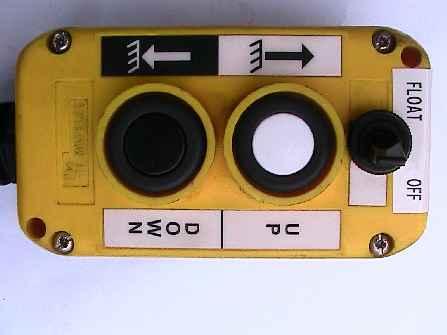
6 Solenoid Valve 4W/2P Valve 4W/2P is four way two position spool valve. With the coil de-energized (and 2W/2P valve energized) flow from the pump lowers the plow. With 4W/2P coil energized the plow is lifted. See figure 1 and 2. Pressure Compensated Flow Control Pressure compensated flow control provide constant regulated flow in one direction (when plow is coming down) regardless of changes in load pressure. Flow in reverse direction (when plow comes up) is non-regulated free flow. Control Switch The M3551 control box has two push buttons and a float switch. One up button and one down button. The up button starts the motor and shifts the 4W/2P valve to lift the plow. The down button starts the motor and shifts the 2W/2P valve to lower plow. If the float switch in float position, it shifts the 2W/2P valve to lower plow partner. If float switch is switched in float position, a blade will drop to the floor. Float switch is used, to facilitate removal of a blade from a truck, or for plowing on uneven surfaces or dragging light snow. If using float switch does not clean a surface, turn off float switch and use down pressure button. Warning: Do NOT use float switch when driving on the road. Do NOT leave a float switch in float position when a vehicle is turned off. A blade will not lift if a float switch is in float position. - Do NOT use float switch when driving on the road. Do NOT leave a float switch in float position when a vehicle is turned off. Page 6
7 Page 7
8 Page 8
9 Page 9
10
11


12 Plug view of B B FPN0919-SA B Plug view of B Page 1 R00
13 Ref # Qty Part # Description 1 1 FP12379 Pump base assembly 1a 1 FP7985 Needle Bearing (Pump Shaft to Pump Base) 2 1 FP0126 Ball, 5/ FP2680 Poppet 4 1 FP0130 Spring 5 1 FP3276 Plug, 9/ FP3274 Plug, ¾ 7 1 FP Flow control 8 1 FP13059 Return tube 9 1 FP13092 Suction tube, 90 degree elbow 10 1 FP13107 Filter screen 11 1 FP14045 Reservoir 12 6 FP7703 Screw, self-tapping, 10mm x 3/ FP18442 Motor, 12VDC 14 1 FP2352 O-ring 15 2 FP7527 Relief valve kit 16 1 FP0490-D Valve assembly, 2 way / 2 position #8 16a 1 FP10861-D Coil 16b 1 FP10907-D Cartridge 17 1 FP10833-D Valve, 4W / 2P 17a 1 FP18835-D Coil 17b 1 FP11111 Cartridge 18 1 FPN0571 Vent plug 19 1 FP7995 Control box, only 20 1 FP1694 Terminal, quick connect 21 1 FP1346 Terminal, ring, 5/16 screw 22 1 FP17757 Solenoid 23 1 FP3414 Terminal #10 stud 24 1 FPN0620-SA Control box and harness assembly 25 1 FPN0919-SA Control Box Harness 26 1 FPN0920-SA Assembly consist of (53607-B & B) 27 1 FP2238 Pump mounting plate 28 2 FP7899 Self-tapping screw, 5/ FP SA Modular pump assembly 30 1 FP2159 Pump shaft seal 31 1 FP2318 Bearing, motor to pump base Page 1 R00
14 FP10907-D was FP0307 *note: if Deltrol cartridge with 3/8 stems FP0307 is replaced with Deltrol cartridge with ½ stem FP10907-D, coil must also be replaced with FP10861-D FP10861-D was FP0496 *note: If coil FP0496 is replaced with FP10861-D, Deltrol cartridge with 3/8 stem must also be replaced with Deltrol ½ stem FP10907-D FP7249-D was FP7249 FP0679-D was FP0679 *note: If Parker cartridge FP0679 is replaced with Deltrol cartridge FP0679-D,Parker coil must also be replaced w/ Deltrol coil FP18835-D FP18835-D replaces FP10977 FP11111 replaces FPN0406 *note: if Parker cartridge FPN0406 is replaced with Deltrol Cartridge FP11111, Parker coil FPN0408 must also be replaced with Deltrol coil FP18835-D FP0490-D was FP0490 FP10833-D was FPN0352 FP18442 was FP8034 FP17757 was FP7518 Page 14
15 Page 15

16 Page 16 M3551
17 Page 17 M3551
18 Page 18 M3551
19 Page 19
20 Page 20 -
21 Page 21 M3551
Arctic Equipment Manufacturing Corporation M3551 Hydraulic Power Unit. Table of Contents
 Arctic Equipment Manufacturing Corporation M3551 Hydraulic Power Unit Table of Contents General Information...2 Hydraulic Information Diagrams...7 Hydraulic and Electrical Installation...10 Parts List...11
Arctic Equipment Manufacturing Corporation M3493 Hydraulic Power Unit. Table of Contents
 M3493 Hydraulic Power Unit Table of Contents Operating information...2 Hydraulic Operational Diagrams...6 Hydraulic & Electrical Installation...10 Parts List...16 Troubleshooting...22 M3493 Power Unit
Table of Contents. M673f- old
 Table of Contents General Information. 2 Hydraulic & Electrical Operational Diagrams.8 Hydraulic & Electrical Installation 17 Parts List...23 Troubleshooting.28 Page 1 M673010-01L06E (old version) Operating
Arctic Equipment Manufacturing Corporation M3500V Hydraulic Power Unit. Table of Contents
 Arctic Equipment Manufacturing Corporation M3500V Hydraulic Power Unit Table of Contents General Information...2 Hydraulic Operational Diagrams...8 Hydraulic & Electrical Installation...19 Parts List...26
Arctic Equipment Manufacturing Corporation M3593 Hydraulic Power Unit. Table of Contents
 Arctic Equipment Manufacturing Corporation M3593 Hydraulic Power Unit Table of Contents General Information...2 Hydraulic Operational Diagrams...8 Hydraulic & Electrical Installation Hi Boy & Hi Boy DLC...13
Arctic Equipment Manufacturing Corporation R04 M673F Power Unit Kit Installation Instructions. M673F installation instructions
 Arctic Equipment Manufacturing Corporation R04 M673F Power Unit Kit Installation Instructions M673F installation instructions Arctic Equipment Manufacturing Corporation R04 M673F Power Unit Kit Installation
Table of Contents M3593
 Table of Contents M3593 Operating information...2 Hydraulic Operational Diagrams...7 Hydraulic Installation M3593 (one piece and MPX).. 12 Hydraulic Installation-HI boy & HI-Boy-DLC...16 High mount Installation
DIAGNOSTIC TROUBLESHOOTING INDEX
 DIAGNOSTIC TROUBLESHOOTING INDEX Curtis Industries, LLC. 111 Higgins Street Worcester, MA 01606 Telephone: (508) 853-2200 Fax: (800) 876-9104 www.snoproplows.com TROUBLESHOOTING INDEX - BY PROBLEM Section
Section 6.1. Implement Circuit - General System. General: TF Configuration TB Configurations Implement Control Valve:
 Section 6.1 Implement Circuit - General System General: TF Configuration... 6.1.3 TB Configurations... 6.1.5 Implement Pump Breakdown... 6.1.6 Operational Description: General... 6.1.7 Compensator Control...
MP18 Stacking Valve System Technical Information Manual
 Electric Drives and Controls Hydraulics Linear Motion and Assembly Technologies Pneumatics Service MP18 Stacking Valve System Technical Information Manual The Drive & Control Company Copyright 1996 Bosch
LogSplitterPlans.Com
 Hydraulic Pump Basics LogSplitterPlans.Com Hydraulic Pump Purpose : Provide the Flow needed to transmit power from a prime mover to a hydraulic actuator. Hydraulic Pump Basics Types of Hydraulic Pumps
Troubleshooting the Transmission Hydraulic System
 Testing and Adjusting IT28F INTEGRATED TOOLCARRIER POWER TRAIN Testing And Adjusting Introduction Reference: For Specifications with illustrations, refer to SENR5974, IT28F Integrated Toolcarrier Power
Form No CE Parts List for:
 Form No. 1000048CE Parts List for: PE55TWP-E110 PE55TWP-E220 MODEL B ELECTRIC HYDRAULIC PUMP Maximum Capacity: 10,000 PSI 8 9 TORQUE SPOOL 110-120 IN. LBS. TORQUE NUT 15-20 IN. LBS. 5 3,4 1,2 VALVE DETAIL
SERVICE PARTS MANUAL
 SERVICE PARTS MANUAL SERIES AND R SNOW PLOWS WITH EIS PLOW LIGHT HARNESS CONNECTIONS FOR GRAVITY HYDRAULICS WITH SERIAL NUMBERS BEFORE G000 WITH SERIAL NUMBERS AFTER G00000 FOR DOWN PRESSURE HYDRAULICS
OCTOPUS SELECTION & INSTALLATION GUIDE Rev. C CRA SERIES CONTINUOUS RUNNING PUMPSET
 A. GENERAL DESCRIPTION: OCTOPUS SELECTION & INSTALLATION GUIDE Rev. C CRA SERIES CONTINUOUS RUNNING PUMPSET Octopus CRA continuous running pumps are very reliable quiet and efficient devices which will
MP18/SIC & SIO Stacking Valve System Technical Information Manual
 Electric Drives and Controls Hydraulics Linear Motion and Assembly Technologies Pneumatics Service MP18/SIC & SIO Stacking Valve System Technical Information Manual The Drive & Control Company Copyright
DESCRIPTION & OPERATION
 DESCRIPTION & OPERATION BRAKE BOOSTER Delco-Moraine Single Diaphragm A combined vacuum-hydraulic unit which uses a combination of intake manifold vacuum and atmospheric pressure to provide power assist.
Introduction. General Information. Systems Operation
 Systems Operation Introduction Reference: For illustrated Specifications, refer to the Specifications For 416, 426, 428, 436, 438, & Series II Backhoe Loaders Transmission, Form No. SENR3131. If the specifications
Troubleshooting flow chart for power unit M3593
 Troubleshooting flow chart for power unit M3593 - Motor does not operate. - Motor operates continuosly - Snow plow does not raise. - Snow plow raises up very slow. - Snow plow will not lower. - Snow plow
REPAIR PROCEDURES MANUAL
 REPAIR PROCEDURES MANUAL PVX Series Vane Pumps A Design Series Step-by-Step Guide to Troubleshooting and Repairing PVX Series Vane Pumps Introduction Thank you for choosing Continental Hydraulics PVX Vane
SNOWDOGG HYDRAULIC REFERENCE XP PLOWS /11 1/22
 SNOWDOGG 16153000 HYDRAULIC REFERENCE XP PLOWS 16992930 05/11 1/22 SNOWDOGG 16153000 HYDRAULIC REFERENCE GENERAL REFERENCE 3 GENERAL TROUBLESHOOTING 5 HARNESS REFERENCE 14 CONTROL REFERENCE 16 HPU DECAL
and RD5000 or by the Utility section in the Series 20 valves. 7. The internal pilot pressure is used to initiate the spool shift when a solenoid is en
 December 2004 SOLENOID OPERATORS ON DIRECTIONAL CONTROL VALVES Solenoid valves us an electric signal to control the flow. BASIC TYPES 1. On Off solenoid valves. When energized, they are either fully on
Driving choice. Delivering dependability.
 Driving choice. Delivering dependability. Commercial 700 Series Transmissions & 100 Series Differentials 700 Series with Connector Shafts 700 Series with Sprocket & Service Brake 100 Series Differential
Model 802 Center Mount Adapter For New Holland 9030 & TV140 Bi-Directional Tractors PARTS CATALOG
 Model 802 Center Mount Adapter For New Holland 9030 & TV140 Bi-Directional Tractors 1 PARTS CATALOG TABLE OF CONTENTS Frame & Tractor Linkage...2,3 Header Linkage & Float Group...4,5 Header Drive Hydraulics
E-72 power unit service manual
 FORM. 1-1047 January 2012 E-72 power unit service manual Meyer Products LLC 18513 Euclid Ave. Cleveland, Ohio 44112-1084 Phone 486-1313 (Area Code 216) www.meyerproducts.com email info@meyerproducts.com
LOAD SENSE SECTIONS. Series 20. Directional Control Valves NEED NEW PIC VALVES STANDARD FEATURES SPECIFICATIONS
 Directional Control Valves LOAD SENSE SECTIONS NEED NEW PIC Series 20 STANDARD FEATURES Control and reduced Dead Band (20I) and Tie Rod Kits SPECIFICATIONS Pressure Rating Foot Mounting Maximum Operating
Definitions of Technical Terms
 Definitions of Technical Terms ABSOLUTE A measure having as it s zero point of base the complete absence of the entity being measured. ABSOLUTE PRESSURE A pressure scale with zero point at a perfect vacuum.
Troubleshooting The Transmission Hydraulic System
 416B, 426B, 428B, 436B, & 438B BACKHOE LOADERS TRANSMISSION Testing And Adjusting Troubleshooting The Transmission Hydraulic System Make reference to the following warning and pressure tap locations for
SERVICE PARTS MANUAL
 SERVICE PARTS MANUAL HD, R & THD SERIES SNOW PLOWS WITH EIS PLOW LIGHT HARNESS CONNECTIONS FOR GRAVITY HYDRAULICS WITH SERIAL NUMBER AFTER: HDG00000 FOR DOWN PRESSURE HYDRAULICS WITH SERIAL NUMBERS AFTER:
SERVICE PARTS MANUAL
 SERVICE PARTS MANUAL HD, R & THD SERIES SNOW PLOWS WITH EIS PLOW LIGHT HARNESS CONNECTIONS FOR GRAVITY HYDRAULICS WITH SERIAL NUMBER AFTER: HDG00000 FOR DOWN PRESSURE HYDRAULICS WITH SERIAL NUMBERS AFTER:
Section 6.1. Implement Circuit - General System. General: TF Configuration TB Configurations Implement Control Valve:
 Section 6.1 Implement Circuit - General System General: TF Configuration... 6.1.3 TB Configurations... 6.1.5 Implement Pump Breakdown... 6.1.6 Operational Description: General... 6.1.7 Compensator Control...
INFORMATION TROUBLESHOOTING GUIDE AND FOR MONARCH D.C. POWER UNITS ON SNO-WAY PLOWS
 INFORMATION AND TROUBLESHOOTING GUIDE FOR MONARCH D.C. POWER UNITS ON SNO-WAY PLOWS Maintenance and Troubleshooting Guide for Monarch D.C. Hydraulic Power Units! WARNING Always wear eye protection and
MODEL D ELECTRIC TWO-STAGE HYDRAULIC PUMP
 l e s i MADE IN U.S.A. FOR HYDRAULIC w i t h ANS I B4 0. 1 Parts List for: SPX Hydraulic Technologies 5885 11th Street Rockford, IL 61109-3699 USA powerteam.com Tech Services: +1 800 477 8326 Fax: +1 800
Service and Parts Manual. Minimum Filtration Required:
 R GRESEN Hydraulics Model V0 Sectional Body Directional Control Valve Service and Parts Manual Maximum Operating Pressure: Minimum Filtration Required: 00 PSI ( bar) 0 Micron The information in this Service
700 Series Transmissions & 100 Series Differentials TECHNICAL SPECIFICATIONS. 700 Series with Sprocket & Service Brake
 Commercial 700 Series Transmissions & 100 Series Differentials 700 Series with Connector Shafts 700 Series with Sprocket & Service Brake 100 Series Differential Output torque 20 ft. lbs. (27.1 N-m) 20
SERVICE PARTS MANUAL
 SERVICE PARTS MANUAL HTV SERIES SNOW PLOW FOR SERIAL NUMBERS AFTER HTV0000 Sno-Way, Down Pressure and EIS are registered trademarks of Sno-Way International, Inc. ProControl, MegaBlade, V-Wing, E-Z Switch,
Form No Parts List for: RWP55 RWP55-4 MODEL C HYDRAULIC PUMP AIR DRIVEN WITH REMOTE CONTROL GENERAL ASS'Y SIDE VIEW SECTION A-A
 Parts List for: Form No. 000339 RWP55 RWP55-4 MODEL C HYDRAULIC PUMP AIR DRIVEN WITH REMOTE CONTROL GENERAL ASS'Y SIDE VIEW 3 9, 0 4 5 6 6 5 4, 3 9,0 SPX Hydraulic Technologies, Rockford, IL 609 USA powerteam.com
Module 5: Valves. CDX Diesel Hydraulics. Terms and Definitions. Categories of Valves. Types of Pressure Control Valves
 Terms and Definitions Categories of Valves Types of Pressure Control Valves Types and Operation of Pressure Relief Valves Operation of an Unloading Valve Operation of a Sequencing Valve Operation of a
MODEL B ELECTRIC HYDRAULIC PUMP
 Parts List for: Form No. 05 STATE RTE. 7 NORTH MAHWAH, NJ 070-995 Tel: (0) 5-9500 Fax: (0) 5-95 HYTORCQAS-C5 HYTORCQAS-C0 MODEL B ELECTRIC HYDRAULIC PUMP, 5 9 7 5, Motor Control Assemblies See sheets 5
Check Valves Check Valves are the simplest form of directional control valves, but they can also be used as pressure controls.
 Check Valves Check Valves are the simplest form of directional control valves, but they can also be used as pressure controls. Standard Check Valve The standard check valve permits free flow in one direction
8-1/2' and 9-1/2' MVP Snowplow Service Parts for Hydraulic Assemblies with Isolation Module Electrical System
 WESTERN PRODUCTS, P.O. BOX 245038, MILWAUKEE, WI 53224-9538 Lit. No. 64291 June 15, 2004 8-1/2' and 9-1/2' MVP Snowplow Service Parts for Hydraulic Assemblies with Isolation Module Electrical System A
3. Fuel System FUEL SYSTEM FUEL INJECTION (FUEL SYSTEM) A: GENERAL. FU(STi)-7
 A: GENERAL. FU(STi)-7") W1860BE.book Page 7 Tuesday, January 28, 2003 11:01 PM 3. Fuel System A: GENERAL The fuel pressurized by the fuel tank inside pump is delivered to each fuel injector by way of the fuel pipe and fuel filter.
W1860BE.book Page 7 Tuesday, January 28, 2003 11:01 PM 3. Fuel System A: GENERAL The fuel pressurized by the fuel tank inside pump is delivered to each fuel injector by way of the fuel pipe and fuel filter.
SERVICE PARTS MANUAL
 SERVICE PARTS MANUAL SERIES SNOW PLOWS FOR PLOW SERIAL NUMBERS AFTER D00000 G00000 007 Sno-Way International 9700D TABLE OF CONTENTS Page PARTS LIST INTRODUCTION... POWER PACK FRAME... BLADES... HYDRAULIC
Torque Converter, Transmission Pump, Screen And Filter
 Page 13 of 27 Transmission Hydraulic System In Forward (Engine Running - Type 2 & 3 Control Valve Shown) (4) Transmission control valve. (5) Neutralizer valve. (6) Neutralizer solenoid. (7) Flow control
MODEL B ELECTRIC HYDRAULIC PUMP
 DIVISION UNEX CORPORATION 333 STATE ROUTE 7 NORTH MAHWAH, N.J. 07430- Tel: (0) -00 Fax: (0) -030 Parts List for: Form No. 0 HYTORCQAS- MODEL B ELECTRIC HYDRAULIC PUMP "A" "A", 4 7 3, 4 Motor Control Assemblies
20 Series. Simplify your pumping needs. s Adhesive Supply Servo Pump:
 20 Series Model 20-02-06 Adhesive Supply Servo Pump Simplify your pumping needs. s Model 20-02-06 Adhesive Supply Servo Pump allows excessive adhesive pressure to self-release back into the pump on shutdown
14A6816H190 GT-2150 (2003) Page 1 of 28 Carburetor
 Page 1 of 28 Carburetor") 14A6816H190 GT-2150 (2003) Page 1 of 28 Carburetor 14A6816H190 GT-2150 (2003) Page 2 of 28 Carburetor TC-640221 1 /P Carburetor (Incl 184 of Engine Parts Lists) 1 TC-640216 1 Throttle Shaft & Lever Assembly
14A6816H190 GT-2150 (2003) Page 1 of 28 Carburetor 14A6816H190 GT-2150 (2003) Page 2 of 28 Carburetor TC-640221 1 /P Carburetor (Incl 184 of Engine Parts Lists) 1 TC-640216 1 Throttle Shaft & Lever Assembly
DIAGNOSTIC FLOW CHART FOR E-58H & E-61H ELECTRO LIFT UNITS WITH TOUCH PAD
 DIAGSTIC FLOW CHART FOR E-58H & E-61H ELECTRO LIFT UNITS WITH TOUCH PAD These charts are intended to be used as an aid in diagnosing problems on the Electro Lift units. They are not a substitute for factory
PNEUMATICS CONTENTS HST-TAMPER
 CONTENTS Tamper Pneumatic Component Locations...2 Manually Releasing Air Brakes... 3 Releasing Air Pressure... 4 Removing Water from Air Tanks... 4 Adjusting Air Compressor Governor... 4 Check/Replace
Page 1 of HP B&S Vanguard Engine
 1405 Page 1 of 41 14 HP B&S Vanguard Engine 1405 Page 2 of 41 14 HP B&S Vanguard Engine Ref # Part Number Qty S/P/F Description BS-28Q777-0647-E1 1 14 HP B&S Vanguard Engine 1 BS-496412 1 Cylinder Assembly
PARTS CATALOG ODYSSEY INCLUDES MOWER
 PARTS CATALOG 8-3350 ODYSSEY INCLUDES MOWER INDEX PAINT ENGINES GENERAL INFO PRODUCT IDENTIFICATION NUMBERS (P.I.N.) OR SERIAL NUMBERS (S/N) ENGINE MODEL, SERIAL AND SPECIFICATION NUMBERS TRACTOR MODEL
3000 psi (207 bar) Output/ min. 115 VAC 10cc (0.61 cu. in.) 24 VDC 12cc (0.73 cu. in.) Discharge Element Output Port.
 Output/ min. 115 VAC 10cc (0.61 cu. in.) 24 VDC 12cc (0.73 cu. in.) Discharge Element Output Port.") MultiPort Lubricator Grease, Injector General The MultiPort Lubricator is an electrically driven multiple outlet lubrication unit design primarily for use with injector systems. The unit includes two pumping
MultiPort Lubricator Grease, Injector General The MultiPort Lubricator is an electrically driven multiple outlet lubrication unit design primarily for use with injector systems. The unit includes two pumping
SERVICE PARTS MANUAL
 SERVICE PARTS MANUAL SERIES SNOW PLOWS FOR PLOW SERIAL NUMBERS AFTER D0000 G0000 00 Sno-Way International 9F TABLE OF CONTENTS Page PARTS LIST INTRODUCTION... POWER PACK FRAME... BLADES... HYDRAULIC SYSTEM
Tech. Services: (800) Fax: (800) Order Entry: (800) Fax: (800)
 Fax: (800) Order Entry: (800) Fax: (800)") SPX Corporation 5885 11th Street Rockford, IL 61109-3699 USA Tech. Services: (800) 477-8326 Fax: (800) 765-8326 Order Entry: (800) 541-1418 Fax: (800) 288-7031 Parts List for: Form No. 108184 RSST-20 Internet
SPX Corporation 5885 11th Street Rockford, IL 61109-3699 USA Tech. Services: (800) 477-8326 Fax: (800) 765-8326 Order Entry: (800) 541-1418 Fax: (800) 288-7031 Parts List for: Form No. 108184 RSST-20 Internet
Chapter 13: Application of Proportional Flow Control
 Chapter 13: Application of Proportional Flow Control Objectives The objectives for this chapter are as follows: Review the benefits of compensation. Learn about the cost to add compensation to a hydraulic
DIAGNOSTIC FLOW CHART FOR E-57 & E-60 ELECTRO LIFT UNITS WITH TOUCH PAD
 DIAGSTIC FLOW CHART FOR E-57 & E-60 ELECTRO LIFT UNITS WITH TOUCH PAD These charts are intended to be used as an aid in diagnosing problems on the Electro Lift units. They are not a substitute for factory
SERVICE PARTS MANUAL
 SERVICE PARTS MANUAL 28V SERIES SNOW PLOWS FOR PLOW SERIAL NUMBERS AFTER 28VG100000 28VD100000 07 Sno-Way International 9710097F TABLE OF CONTENTS Page PARTS LIST INTRODUCTION... 2 POWER PACK FRAME...
Repair instruction for HYDRAULIC DRIVE UNITS HA1ES / HA \r04eng 0697
 Repair instruction for HYDRAULIC DRIVE UNITS HA1ES / HA2 Contents list page Safety rules General instructions 1 Operating faults and how to clear them 2 Replacement parts lists 31070 HA1ES 4 31375 HA2
CH.4 Basic Components of Hydraulic and Pneumatic System/16 M HAP/17522/AE5G
 Content : 4.1 Hydraulic and Pneumatic actuators. 10 Marks Hydraulic Actuators - Hydraulic cylinders (single, double acting and telescopic) construction and working, Hydraulic motors (gear and piston type)
liu OIL TRANSFERING BETWEEN
 4007-9 When the lift spool is in the float position, oil from the pump flows through the open center passage to the outlet. The two work ports are directly connected through the hollow center of the spool.
GXV530 DXA2 PARTS CATALOGUE
 GXV530 DXA2 PARTS CATALOGUE E-12 FAN COVER 001 16711-Z0A-000 STAY, FUEL PUMP 1 002 17211-Z0A-003 ELEMENT, AIR CLEANER 1 1022925 002 17211-Z0A-013 ELEMENT, AIR CLEANER 1 1022926 003 17218-Z0A-000 FILTER,
INSTRUCTION MANUAL INTERNAL GEAR PUMP TITAN G-4124A SERIES=> FLANGED TITAN G-124A SERIES => FLANGED MODELS:
 INSTRUCTION MANUAL INTERNAL GEAR PUMP TITAN G-4124A SERIES=> FLANGED TITAN G-124A SERIES => FLANGED MODELS: G-H, G-HL, G-K, G-KK, G-L, G-LQ, G-LL, GLS, G-Q, G-QS 1 Contents Maintenance Thrust bearing adjustment
DIAGNOSTIC FLOW CHART FOR V-68 ELECTRO LIFT UNIT
 DIAGNOSTIC FLOW CHART FOR V-68 ELECTRO LIFT UNIT These charts are intended to be used as an aid in diagnosing problems on the V-68 unit. They are not a substitute for factory training and experience. Be
E/H HYBRID 24 VOLT SYSTEM
 E/H HYBRID VOLT SYSTEM -0 . Attach adapters to E/H valve and install inside cavity on headache rack.. Attach valve harness per diagram on decal.. Attach return hose to valve and filter housing. Attach
Tech. Services: (800) Fax: (800) Order Entry: (800) Fax: (800) MODEL C ELECTRIC HYDRAULIC PUMP
 Fax: (800) Order Entry: (800) Fax: (800) MODEL C ELECTRIC HYDRAULIC PUMP") SPX Corporation 5885 11th Street Rockford, IL 61109-3699 USA Internet Address: http://www.powerteam.com Tech. Services: (800) 477-8326 Fax: (800) 765-8326 Order Entry: (800) 541-1418 Fax: (800) 288-7031
SPX Corporation 5885 11th Street Rockford, IL 61109-3699 USA Internet Address: http://www.powerteam.com Tech. Services: (800) 477-8326 Fax: (800) 765-8326 Order Entry: (800) 541-1418 Fax: (800) 288-7031
INFORMATION AND TROUBLESHOOTING GUIDE
 INFORMATION AND TROUBLESHOOTING GUIDE FOR MONARCH M Series D.C. HYDRAULIC POWER UNITS For the most up-to-date version of this guide Please visit our website @ www.monarchhyd.com General Information THIS
PARTS BOOK CATALOG IMPLEMENT ASSEMBLIES STANDARD BOOM 3PT HITCH MOUNT
 PARTS BOOK CATALOG IMPLEMENT ASSEMBLIES STANDARD BOOM 3PT HITCH MOUNT DIAMOND MOWERS, Inc. 350 E 60 th St. North Sioux Falls, SD 57104 FOR WARRANTY CALL DIAMOND MOWERS DIRECT: 888-960-0364 OUR TECHNICIANS
GROUP 11 HYD. PUMPS & VALVES
 GROUP 11 HYD. PUMPS & VALVES T944 EXTENDO PUMP INSTALLATION, FL-14490... 11-2 PUMP ASSEMBLY, LL-7500-11... 11-4 PUMP ASSEMBLY, LL-7500-11, (PUMP SECTION, LL-7501-15)... 11-6 PUMP ASSEMBLY, LL-7500-11,
SERVICE PARTS MANUAL
 SERVICE PARTS MANUAL VHD SERIES SNOW PLOW WITH SERIAL NUMBERS AFTER VHD00000 and VHD100000 Sno-Way, Down Pressure and EIS are registered trademarks of Sno-Way International, Inc. ProControl, V-Wing, Revolution
ELECTRIC HYDRAULIC PUMP
 Parts List for: Form No. 1000048 PE55TWP PE55TWP-220 MODEL D ELECTRIC HYDRAULIC PUMP Maximum Capacity: 10,000 PSI See Back Sheet 5 of 8 1 13 2,3 11 OFF ON WARNING 6 4,5 0IL 7 VALVE DETAIL TORQUE SPOOL
EFC. Electronically Adjustable Proportional Pressure Compensated Flow Control
 Engineering & Manufacturing Solutions Specifications: See flow chart for capacity. 3000 psi (207 bar) rating. Weighs 8-1/2 lbs. (3.9 kg). Standard Port size #12SAE (1-1/16 12). 10-Micron Filtration Recommended.
Section 6.1. Implement Circuit - General System. General: Implement Control Valve:
 Section 6.1 Implement Circuit - General System General: Implement Circuit... 6.1.3 Implement Pump Breakdown... 6.1.4 Operational Description: General... 6.1.5 Compensator Control... 6.1.6 Standby Condition...
GPM Hydraulic Consulting, Inc. P.O. Box 689. Social Circle, GA Hydraulic Consulting, Inc
 Hydraulic Consulting, Inc This special promotional CD is to demonstrate how your hydraulic troubleshooting manual can be ordered as an Adobe Acrobat ebook. It can be installed on any computer with the
LECTURE 15 TO 17 DIRECTIONAL CONTROL VALVES FREQUENTLY ASKED QUESTIONS
 LECURE 15 O 17 DIRECIONL CONROL VLVES FREQUENLY SKED QUESIONS 1. Explain briefly the function of directional control valves o o start, stop, accelerate, decelerate and change the direction of motion of
Section 6.1. Implement Circuit - General System. General: Implement Control Valve: Implement Circuit
 Section 6.1 Implement Circuit - General System General: Implement Circuit... 6.1.3 Implement Pump Breakdown... 6.1.4 Operational Description: General... 6.1.5 Compensator Control... 6.1.6 Standby Condition...
OCTOPUS SELECTION & INSTALLATION GUIDE
 OCTOPUS SELECTION & INSTALLATION GUIDE CRB SERIES CONTINUOUS RUNNING PUMPSET A. GENERAL DESCRIPTION: Octopus CRB pumpsets are heavy duty, continuously running, electric motor driven pumps which are used
5-2 FUEL SYSTEM AND THROTTLE BODY FUEL SYSTEM FUEL DELIVERY SYSTEM The fuel delivery system consists of the fuel tank, fuel pump, fuel filters, fuel f
 FUEL SYSTEM AND THROTTLE BODY 5-1 FUEL SYSTEM AND THROTTLE BODY I CONTENTS FUEL SYSTEM 5-2 FUEL DELIVERY SYSTEM 5-2 FUEL PUMP 5-3 FUEL PRESSURE REGULATOR 5-4 FUEL INJECTOR 5-4 FUEL PUMP CONTROL SYSTEM
SERVICE PARTS MANUAL
 SERVICE PARTS MANUAL 9, 9T & SERIES SNOW PLOWS WITH EIS FOR PLOW SERIAL NUMBERS AFTER 9G100000, 9D100000, 9C100000 9TG100000, 9TD100000, 9TC100000 G10000, D100, C10000 00 Sno-Way International 910089H
What is hydraulic power pack?
 What is hydraulic power pack? What are the hydraulic power pack applications? Mobile hydraulics applications increasing so much with hydraulic power pack recently. Such as, dump trailers, electric sanitation
Hydraulics Troubleshooting
 Hydraulics Troubleshooting Hydraulic Power Units When there is a problem with a KTI Power Unit; from the pump tag we need the Model, Serial Number, Date and the last 6 digits of the trailer VIN#. An option
ARC4800L Big Red Compressor System
 350 S. St. Charles St. Jasper, In. 47546 Ph. 812.482.2932 Fax 812.634.6632 on the internet: www.ridetech.com ARC4800L Big Red Compressor System 2 ARC7000 ViAir 400C 150psi compressors 2 F9242 5 gallon
P773-2 For Model: M773LW2 PARTS MANUAL. Marine Generators Marine Diesel Engines Land-Based Generators
 P773-2 For Model: M773LW2 PARTS MANUAL Marine Generators Marine Diesel Engines Land-Based Generators CALIFORNIA Proposition 65 Warning: Diesel engine exhaust and some of its constituents are known to the
STX-26 Stump Grinder
 Form No. 3365-311 Rev B STX-26 Stump Grinder Model No. 23210 Serial No. 310000001 and Up Model No. 23210G Serial No. 310000001 and Up Register at www.toro.com. Original Instructions (EN) *3365-311* B Ordering
Welker Sampler. Installation, Operation, & Maintenance Manual. Model GSS-4HP
 Installation, Operation, & Maintenance Manual Welker Sampler Model GSS-4HP The information in this manual has been carefully checked for accuracy and is intended to be used as a guide to operations. Correct
OPERATION AND SERVICE MANUAL. McGILL UNIVERSITY PROJECT: MCS-3237 SUBJECT: HYDRAULIC POWER UNIT AND ROTARY ACTUATORS DECEMBER 2001
 OPERATION AND SERVICE MANUAL McGILL UNIVERSITY PROJECT: MCS-3237 SUBJECT: HYDRAULIC POWER UNIT AND ROTARY ACTUATORS DECEMBER 2001 CONTENTS 1. DESCRIPTION OF HYDRAULIC COMPONENTS... 3 1.1. HYDRAULIC POWER
PARTS MANUAL P For Models: NL773LW4 and NL773LW4E.
 PARTS MANUAL P773-4 For Models: NL773LW4 and NL773LW4E www.northern-lights.com CALIFORNIA Proposition 65 Warning: Breathing Diesel engine exhaust and some of its constituents are known to the State of
Input, Control and Processing elements
 PNEUMATIC & HYDRAULIC SYSTEMS CHAPTER FIVE Input, Control and Processing elements Dr. Ibrahim Naimi Valves The function of valves is to control the fluid path or the pressure or the flow rate. Depending
Installation and Service Instructions for 87,000 & 87,100 Series Self-Adjust Brakes (rev. B)
") Spring-Set Disc Brakes P/N 8-078-98-0 effective 6/6/0 Installation and Service Instructions for 87,000 & 87,00 Series Self-Adjust Brakes (rev. B) Tools required for installation and servicing: 3/8 hex
Spring-Set Disc Brakes P/N 8-078-98-0 effective 6/6/0 Installation and Service Instructions for 87,000 & 87,00 Series Self-Adjust Brakes (rev. B) Tools required for installation and servicing: 3/8 hex
Straight Blade Service Parts for Hydraulic Assemblies and Lighting Assemblies
 WESTERN PRODUCTS, P.O. BOX 245038, MILWAUKEE, WI 53224-9538 Lit. No. 66961 January 5, 2004 Straight Blade Service Parts for Hydraulic Assemblies and Lighting Assemblies A DIVISION OF DOUGLAS DYNAMICS,
STX-26 Stump Grinder
 Form No. 3383-656 Rev B STX-26 Stump Grinder Model No. 23208 Serial No. 314000001 and Up Model No. 23208G Serial No. 314000001 and Up Register at www.toro.com. Original Instructions (EN) *3383-656* B Ordering
Illustrated Parts List to
 Illustrated Parts List Model Series 171400 to 171499 TYPE NUMBERS 0035 through 0131, 0235, 0249, 0270, 0300 through 0308, 0435 through 0470, 0500 through 0505, 0520 through 0535, 1035, 1049, 1070, 1100,
P843NSATS For Models: NL843N2, NL843NW2, and NL843NW3 PARTS CATALOG. Marine Generators Marine Diesel Engines Land-Based Generators
 P843NSATS For Models: NL843N2, NL843NW2, and NL843NW3 PARTS CATALOG Marine Generators Marine Diesel Engines Land-Based Generators CALIFORNIA Proposition 65 Warning: Diesel engine exhaust and some of its
Form No , 3 4, 5 VALVE DETAIL DIVISION UNEX CORPORATION. Parts List for: HYTORC-115 HYTORC-230 HYTORC MODEL D ELECTRIC HYDRAULIC PUMP
 > Parts List for: Form No. 105548 DIVISION UNEX CORPORATION 333 STATE ROUTE 17 NORTH MAHWAH, N.J. 07430-9895 Tel: (201) 512-9500 Fax: (201) 512-0530 HYTORC-115 HYTORC-230 HYTORC-230-2 MODEL D ELECTRIC
Whisper Pump Service and Repair Guide
 Hydraulics Courtesy of CMA/Flodyne/Hydradyne Motion Control Hydraulic Pneumatic Electrical Mechanical (800) 426-5480 www.cmafh.com VPV Vane Pump Whisper Pump Service and Repair Guide Welcome to the Service
Fluid Maintenance. The hydraulic oil performs four functions in the hydraulic system:
 The hydraulic oil performs four functions in the hydraulic system: Transmits Energy Coolant Lubricant Sealant Viscosity Viscosity is the rating of the oil thickness or resistance to flow. Viscosity is
Illustrated Parts List
 FORM MS 4183 10/31/2006 REPLACES FORM MS 9748 7/1997 FILE IN SECT. 2 OF SERVICE MANUAL 290700 Illustrated Parts List Model Series 290700 TYPE NUMBERS 0100, 0102, 0106, 0107, 0108, 0333, 0402, 0410. TO
Constant Speed Control
 Eaton Heavy Duty Hydrostatics No. 4-51 June, 1995 Installation & Operating Instructions Constant Speed Control Operating Instructions for Constant Speed Control (The valve package, speed sensor and electronic
Warranty Approval. Visual Inspection of Starters & Alternators
 Warranty Approval Visual Inspection of & Alternators Is it Genuine Delco Remy? 37MT, 41MT & 42MT Older Delco Remy stamp Current ink stamping 38MT & 39MT Current stamping Current reman label Stamped customer
Illustrated Parts List
 FORM MS 0670 3C 8/2001 REPLACES FORM MS 0670 2Q 11/2000 FILE IN SECT. 2 OF SERVICE MANUAL Illustrated Parts List Model Series TYPE NUMBERS 0042 through 1256. For Use On Engines Built Before Date Code 01070100.
E-12-1 FAN COVER (TAE2,TAF2)
") E-12-1 FAN COVER (TAE2,TAF2) 001 16715-ZJ1-840 COVER, FUEL PUMP 1 003 19611-ZJ1-850ZC COVER, FAN (RECOIL STARTER) *R280 * 1 1003896 004 19612-ZJ1-841 PLATE, SIDE 1 005 19614-ZJ1-841 PLATE, SIDE 1 006 19621-ZJ1-801ZC
E-12-1 FAN COVER (TAE2,TAF2) 001 16715-ZJ1-840 COVER, FUEL PUMP 1 003 19611-ZJ1-850ZC COVER, FAN (RECOIL STARTER) *R280 * 1 1003896 004 19612-ZJ1-841 PLATE, SIDE 1 005 19614-ZJ1-841 PLATE, SIDE 1 006 19621-ZJ1-801ZC