OPERATION AND SERVICE MANUAL. McGILL UNIVERSITY PROJECT: MCS-3237 SUBJECT: HYDRAULIC POWER UNIT AND ROTARY ACTUATORS DECEMBER 2001
|
|
|
- Quentin Mosley
- 5 years ago
- Views:
Transcription
1 OPERATION AND SERVICE MANUAL McGILL UNIVERSITY PROJECT: MCS-3237 SUBJECT: HYDRAULIC POWER UNIT AND ROTARY ACTUATORS DECEMBER 2001
2 CONTENTS 1. DESCRIPTION OF HYDRAULIC COMPONENTS HYDRAULIC POWER UNIT HEAT EXCHANGER ACCUMULATOR MANIFOLD ROTARY ACTUATORS FILTRATION RECOMMENDED OIL START-UP AND SYSTEM FLUSHING PRELIMINARY INSPECTION START-UP PROCEDURES SYSTEM FLUSHING ADJUSTMENTS MAINTENANCE AND REPAIR COMPONENT REPAIR RECOMMENDED MAINTENANCE TROUBLESHOOTING REPLACEMENT PARTS HYDRAULIC SCHEMATICS TECHNICAL INFORMATION
3 1. DESCRIPTION OF HYDRAULIC COMPONENTS This section of the manual provides a brief description of the main hydraulic components required for the proper functioning of the hydraulic system. Additionally, you will find information regarding the functions and adjustment parameters of the hydraulic components. Refer to section 6 of this manual for a complete technical specifications listing HYDRAULIC POWER UNIT The hydraulic unit is required to operate the two new rotary actuators and the existing one OIL RESERVOIR The reservoir required has a capacity of 100 U.S. gallons of hydraulic oil. Two (2) access doors are located on each end the reservoir. One (1) suction port is available for the hydraulic pump. There is one (1) intank style filter installed on the top of the reservoir HYDRAULIC PUMP The hydraulic power unit has one hydraulic pump, variable flow and pressure compensated type. It will vary the oil flow to keep a constant pressure into the circuit. The pump has a capacity of 21 GPM (gallon per minute) at 1800 RPM. There are three adjustments available on the pump, which are the load sensing, the compensator and the flow limiter. The first adjustment is not used in your system configuration and SHOULD NOT BE MODIFIED. The second adjustment has for function to control the system pressure. AT ANY MOMENT, THE PUMPS PRESSURE SHOULD NOT BE UNDER 400 PSI. A pressure under this value will harm to the pump s lubrication and can damage it. The hydraulic circuit configuration requires a pressure of 3000 PSI. The flow limiter has for function to limit the maximum flow supplied by the pump. For your set-up, this adjustment SHOULD NOT BE MODIFIED. 3

4 (flow limiter on back, not shown on this picture) ELECTRIC MOTOR A 40 HP at 1800 RPM, 3 phase, 600 volt motor is required to drive the pump RESERVOIR ACCESSORIES To complete the H.P.U., the reservoir must be equipped with some other accessories. These are : a breather, one (1) temperature switch, a level and temperature indicator, one (1) electric level indicator, one (1) suction strainer and two (2) ball valves to fill and drain the reservoir HEAT EXCHANGER In order to extract the heat transmitted to the hydraulic fluid, the oil must circulate through a oil/water type cooler. The oil coming from the return line will pass through the cooler. If the pressure increases and reaches 30 PSI, due to the restriction made by the cooler, the excess of flow will bypass the cooler by the check valve installed in parallel. A thermostatic valve senses the oil temperature into the reservoir and control the water flow going to the cooler. A solenoid valve, installed upstream of the thermostatic valve, will close and block the water going to the cooler, when the hydraulic power unit will stop. 4
5 1.3. ACCUMULATOR MANIFOLD To ensure a stable pressure, an accumulator is installed on the pressure line. The accumulator manifold has a pressure relief valve and a dump valve. The pressure relief valve s function is to protect the circuit in case of too high pressure. The dump valve is a normally opened solenoid valve, which is energized when the hydraulic pump is turned on. If the pump is stopped, all the pressure contained in the pressure line and the accumulator is dumped to the reservoir. An orifice downstream the dump valve prevents shocks into the return line by limiting the flow going to the reservoir. A pressure test point is available to measure the supply pressure. The diaphragm type accumulator is connected to the accumulator manifold. The nitrogen pressure is 2400 PSI. It should be at approximately 80% of the system pressure ROTARY ACTUATORS The actuators supplied are equipped with a Moog proportional valve, a pressure reducing valve, a cam, a directional valve mechanically activated and a potentiometer Moog proportional valve The Moog D is a proportional valve, 4 way, 10% overlap and linear flow characteristic. The command signal is +/-10 Volts and the feedback is +/-10 Volts with dead band compensation. The valve s electronics will compensate for the 10% overlap of the spool. The valve is also equipped with an electrical fail-safe. In order to move the spool to the safe centered position, the two control chambers of the main stage are hydraulically short circuited by a 4 way / 2 positions solenoid valve. The spring force move the spool into overlapped centered position. 5
6 Pressure reducing valve The pressure reducing valve can be used to reduce pressure downstream of it. By reducing the pressure supplied to the actuator, the maximum torque applied by the actuator is reduced. For maximal performances, the pressure should be 3000 PSI Directional valve The directional valve mechanically operated function is to block the pressure going to the Moog proportional valve if it is activated by the cam Cam The cam has been machined to allow a rotation of +/-20 degrees Potentiometer The potentiometer has a 5K resistance and the theoretical electrical travel is 340 degrees +/-5 deg FILTRATION The hydraulic system has two types of filtration. There are the high pressure and the low pressure filters. All original filter assemblies are equipped with filtration elements rated at 99.5% efficiency (ß 3 ] 200). The filters are equipped with electrical clogging indicators. These indicators can either be normally opened or normally closed. They give an indication of the filtration elements condition. The indicators will shift when the pressure differential between the inlet and the outlet exceeds approximately 116 PSI for the high pressure filter and 32 PSI for the low pressure filter. Generally, when an indicator shifts the electrical logic, it means that the filter element needs to be changed. However, when starting up during cold conditions, the oil has a higher viscosity rating than it would during normal temperature operating conditions. The higher viscosity rating could have the same effect on the indicator as a clogged filter element. To avoid changing filter elements 6
7 unnecessarily, we recommend that the indicators be checked only when the system reaches a normal operating temperature. The return (or low pressure) filter is equipped with a bypass mechanism for the filter element. This mechanism opens only when the pressure differential pressure between the filter s inlet and the outlet is 51 PSI. This is used to protect the filter element against high pressure which could damage it or collapse it. Even though the indicators seem to indicate that the filter elements are still good, we strongly recommend to change the elements at regular intervals (e.g., during a regularly scheduled shut-down or approximately every 6 months) HIGH PRESSURE FILTRATION The high pressure filter is installed at the pump s outlet and is nonbypass type. It features a 3000 PSI collapse rating which will eliminate all possible contamination risks downstream the filter. The element is rated at 3 micron absolute (ß 3 ] 200) LOW PRESSURE FILTRATION The low pressure filter is installed on the H.P.U.. It has a bypass valve prevent back-pressure in the return line which could damage the filtration element. The element is rated at 3 micron absolute (ß 3 ] 200) RECOMMENDED OIL There are several types of oil available on the market. That which concerns us is oil designed for hydraulic systems. In this category, oils are classified according to their viscosity and the additives contained therein. For your hydraulic system, we recommend Shell Tellus 32, Tribospec Corporation s Sunvis 700, or all equivalent oils. Because of certain components construction and precision machining of internal parts, the system s oil must be maintained at a certain cleanliness level. According to ISO code DIS 4406 (SAE J1165), Moog recommends ISO cleanliness level of 14/11 (or better) with a maximum of 16/13 for all servovalves and proportional valves. Hydraforce recommends a cleanliness level of ISO code 18/14 for its cartridge valves. ISO code 14/11, being the most stringent of the hydraulic system, is therefore the cleanliness level to be maintained in order to maximise both system performance and component life. The efficiency level of the hydraulic system is directly linked to the overall performance. 7
8 2. START-UP AND SYSTEM FLUSHING The recommendations which follow concern the start-up procedure. This procedure must be followed after every prolonged system shut-down and especially following repairs to the system PRELIMINARY INSPECTION Prior to engaging the electric motor: - Check fluid level in the reservoir. The level must be near the upper limit of the level indicator. Top up, if necessary, with clean and filtered fluid (the use of a portable filtration unit, available at, is strongly recommended). - Verify that pump housing is filled with fluid. Unscrew the upper-most fitting on the pump. If required, fill with clean fluid. - If the pump has been repaired or replaced, make sure that it has been properly mounted on the electric motor, that all connections have been tightened, and that the pressure compensator screw has been properly adjusted. - Check accumulator precharge pressure. It should be approximately 2400 PSI. Use a charging unit (available at ). - If a component has been removed for repair or replacement, ensure that it has been properly reinstalled according to schematic specifications, material lists, or to specific mounting instructions. - If a hydraulic line has been disconnected, ensure that it has been correctly reinstalled according to specifications or to proper installation procedure. 8
9 2.2. START-UP PROCEDURES NOTE : Read section 2.3 if a flushing is required for a part of the system or section 2.4 for the whole system if some components requires settings. Connect the PSI gauges to the test points located on the accumulator manifold. Start the electric motor. - If work has been carried out on the motors' electric line, verify its rotation. Remove the plastic cover located on the pump/motor adapter and, using a marker, indicate the direction of rotation. Effect short "start-stop" sequences to confirm motor rotation. For a pump with a clock-wise rotation, the motor's rotation will usually be the opposite (i.e., counter-clockwise). A pump's rotation must always be checked with the shaft facing the technician. If required, the motor's rotation may be changed by inverting the two wires in the feed cable (check rotation again). Replace plastic cover. - Re-initiate short "start-stop" sequences to charge the pump. Check for fluid leaks and/or unusual noises and correct as required. Also check the gauge's needle. The pump must operate smoothly under stable pressure after charging. - Pay particular attention to start-ups effected under cold conditions : Cold fluids are very viscous and could cause premature pump wear or breakdown. Startups are not recommended when system fluid temperature is inferior to 10 C (50 F). - Keep watch of the reservoir's fluid level. Fill as required with clean and filtered fluid (see section 2.1) SYSTEM FLUSHING A system flushing is required if a repair is made on a hydraulic component located upstream a sensitive component to the contamination which there can be in oil. A premature start-up without proper flushing could lead to costly repairs as well as a loss of production time. While most major fluid suppliers offer specially-designed fluids exclusively for hydraulic system flushing, standard system fluid may be used for flushing so 9
10 long as it is initially clean. Best results are achieved when the system fluid temperature is high and the flow is turbulent PREPARATION FOR SYSTEM FLUSHING While a system flushing is a procedure which requires a certain amount of preparation, it plays an important role in ensuring prolonged life for the implicated components. If the flushing procedure is improperly carried out or ignored, components in the hydraulic circuit may become damaged. The following are the recommended steps to follow for a proper flushing: 1) Install a flushing element in the high pressure filter assembly. We suggest elements rated at 3 microns absolute. 2) Replace the return line filter element with new element. Again, We suggest elements rated at 3 microns absolute. 3) Isolate all proportional valves in the circuit being rinsed. This may be achieved by any of the following methods : a) Replacing the proportional valves by directional valves; b) Replacing the proportional valves by specially-designed rinsing plates; Note : We suggest that the proportional valves be properly stored in sealed plastic bags whenever removed from their manifolds. c) Linking the pressure (P) line to the return line (T) leading to the manifolds of the particular valve to be isolated. 4) Heat the reservoir oil to approximately 50 C (122 F) if required. To do so, follow the instructions as listed in 3). If option 3a) has been undertaken, then proceed according to 4a) if not, proceed according to 4b). a) Start the pump and adjust the pumps compensator to approximately 500 PSI (see the notes lower). Activate each of the directional valves so as to ensure proper circulation of the oil in the circuit. Leave circulate for about 1.5 to 2 hours. 10
11 b) Close the pressure ball valve at pump outlet as well as the one at the low pressure filter s inlet. Adjust the pump compensators to approximately 500 PSI. Completely open the pressure valve first. Then, slowly open the return valve until the pressure equals the pump s pressure or until the pump starts to grumble. In the case of the latter condition, close the return valve until the pump begins to operate normally. Leave circulate for about 1.5 to 2 hours. Notes : - It is important to reduce system pressure to approximately 500 PSI to reduce the possibility pressure spikes in the system and to avoid damaging the rinsing elements; - Regularly verify the pump s pressure because, as the oil temperature rises, viscosity diminishes therefore causing pressure to drop. The pump s pressure should never go under 400 PSI under risk to damage the pump; - Regularly check oil level in the reservoir if a major intervention occurred in the system and a large quantity of air has been introduced in the piping. Add clean oil as required. 5) Stop the system and allow the oil to cool. 6) Change rinsing element for a new high pressure filter element (see section 4). 7) Change the return filter element (low pressure) for new filter element (see section 4). 8) Re-install the proportional valves or reconnect the hoses to their original positions. 9) Completely open the return line ball valve and completely close the ball valve on the pressure line. 10) Re-start the pump and re-adjust the pump compensator to its original value. 11) Slowly open the pressure line ball valve to pressurize the system. 12) Re-verify reservoir oil level. 11
12 Note : It is important to keep all affected areas, components, and personnel involved with the flushing as clean as possible. It is imperative to undertake all possible precautions to avoid contaminating the components or the hydraulic circuit with foreign particles or with liquid other than the hydraulic fluid being utilised ADJUSTMENTS The hydraulic system uses some components that requires adjustments (like pressure, flow and temperature) and those adjustments can be modified to obtain the best system s performances. The hydraulic system can be considered as a prototype during the start up. The following adjustments are suggested to obtain good performances. However, during start up, some re-adjustments should be necessary. Refer to section 5 for parts listing and section 6 for all technical details ADJUSTABLE COMPONENTS ON THE H.P.U. Components featuring adjustments on the hydraulic power unit (H.P.U.) are the pump s compensator, the temperature switch, the relief valve and the thermostatic valve PUMP S COMPENSATOR ADJUSTMENT On the pressure compensated pump, two adjustments are possible. One adjustment is the maximum flow that the pump can supply while and the other is the system pressure (see section 1.1.2). - Pump pressure compensator : This is used to limit the system pressure. For ideal system performance, the pressure compensator must adjusted at 300 PSI. The maximum pressure adjustment can be up to 4000 PSI. - Pump flow limiter : This is used to limit the flow supplied to the system. This adjustment requires the use of a flow meter. This adjustment must therefore be carried out by qualified personnel using the proper 12
13 equipment. Consequently, this adjustment must not be modified (original adjustment) TEMPERATURE SWITCH There is one temperature switch installed on the reservoir. It should be set at 65 C (150 F). Its function is to shut down the hydraulic system in order to avoid causing damage to the circuit s components due to over-heating problem THERMOSTATIC VALVE The thermostatic valve regulates the water flow going through the oil cooler. It can be adjusted between 1 and 5 which corresponds to the opening temperature to allow the water going to the cooler. The numbers 1 is equivalent to 25 C (77 F) and 5 is equivalent to 65 C (150 F). The valve is set at 3 (110 F). 3. MAINTENANCE AND REPAIR The trouble-free functioning of a hydraulic system begins with proper maintenance and adequate repair of system components when required. However, as is true with all machines, some components may break down without notice. System performance may be severely compromised due to improper use or incorrect settings. Section 3.3 describes some of the most common problems that may occur in the hydraulic system COMPONENT REPAIR Some components (e.g., reservoir accessories, cartridge valves, other standard valves, strainers, etc.), because of their relatively low cost, may not be economically repairable. Other components, such as accumulators, oil coolers, filter heads, and flow regulators are not prone to breakdown if they are used under normal operating conditions. Even such components such as pumps, solenoid valves, servovalves and cylinders should be replaced by new units in case of breakdown in order to 13
14 reduce down-time. By using this strategy, the defective units may be repaired and subsequently be used as spares. Section 6 provides a detailed description of these components along with the related technical information required to repair the defective parts. Section 4 provides a partial list of the most commonly required replacement parts. The manufacturer recommends that these parts should be kept in stock as their failure is one of the major causes of system stoppages. The repair and reconditioning of the majority of the system's components must be undertaken by qualified technicians in a clean and well equipped environment designed for that purpose. If your personnel does not have these qualifications, it is recommended that the components be forwarded to a hydraulics specialist (i.e., ) RECOMMENDED MAINTENANCE The principle source of system stoppages in hydraulic systems is dirt (e.g., dust) and most particularly fluid contamination. A clean system operating in a clean environment will function for longer periods of time with greater performance and efficiency. Therefore : - Change filter elements regularly (e.g., every 2000 hours of operation or once par year) or when notified by the status of filter indicators. Even though changing elements may require that the system be shut down, the little time this action take could very well save hours or even days of down time caused by contaminated pumps or servovalves. Note : During cold condition start-ups, filter indicators may indicate that the elements are obstructed. This is caused, however, by the fluid's high viscosity. The filter indicators must therefore only by considered when fluid temperature nears normal operating levels (30 C). - Keep the system clean. Do not allow dust or foreign materials to accumulate on components or hoses and most particularly on the top of reservoirs in which particles may fall into during inspections or opening of the breather cap. Stop leaks as soon as they are detected. Not only will leaks cause fluid loss, but dust particles will 14
15 also be introduced into the system. Problems may be more easily pin-pointed and solved when a system is kept clean. - If the system's environment is excessively dirty, precise measures must be taken to prevent dirt from accumulating and gaining access to the system through the breather cap. - Two other major causes of hydraulic system shut-down or loss of performance are excessive fluid temperatures and insufficient fluid levels in the reservoir. - Do not allow the system to operate at an excessively high temperature (e.g., greater than 65 C (150 F)). High temperatures lead to the following problems : Low fluid viscosity and degradation, an increase in internal leaks, acceleration of component wear, reduction in the joints' useful operating life, modification of valve function, etc. It is important to locate problems and to correct them immediately. We also recommend to daily check the following points. This will enable you to make a certain preventive maintenance on the machine. - An inspection of the reservoir (for any openings on the surface); - A cursory inspection of all manifold hoses and tubing for any apparent leaks; - List any and all abnormal noises, shocks or vibrations in the conduits; - Make a report of all mechanical problems (e.g., excessive friction, jerky or abrupt movements, etc.). As was mentioned in section 2.3, a complete system flushing should be undertaken after a stoppage caused by the breakdown of a component. A partial flushing is sufficient if the breakdown occurs past the component's protection filter. A complete system cleaning and flushing should be undertaken at least once per year. Carefully inspect and clean all components and repair or replace any defective part to keep the system functioning at perk performance levels. 15
16 3.3. TROUBLESHOOTING This section lists the major causes of the most frequently encountered hydraulic system breakdown problems (consult a hydraulics specialist, e.g.,, for problems not listed below). The first step in diagnosing any system problem is to start looking for the furthest point up the line (from the pump) where it is known that the system is functioning properly. Afterwards, follow the flow's direction and effect a component-by-component check until the faulty part is located. ABSENCE OF FLOW: - The electric motor(s) is (are) not functioning; - The pump is not coupled to the electric motor; - Fluid level is low; - The pump is not primed; - The pump is defective; - The flow regulating valve(s) on the manifold is (are) not completely open or closed. FLOW IS WEAK: - The pump is defective; - A component of the hydraulic circuit leaks. ABSENCE OF PRESSURE: - Absence of flow (see above); - The pump is defective; - The pressure regulating valve is either completely open or adjusted too close to the recommended minimum pressure. LOW PRESSURE: - The pressure compensator's adjustment is too low; - The pump is defective; - The pressure regulating valve is either adjusted too low or partially open. NOISY OPERATION: - Fluid temperature is too low (cavitation); - Breather is obstructed (cavitation); - Strainer is obstructed (cavitation); 16
17 - Pump suction valve is partially closed (cavitation); - Fluid level in reservoir is too low (aeration); - Connections improperly fastened on the suction line (aeration); - Pump is worn; - Couplings worn or improperly fastened; - Incorrect pump rotation; - The pressure regulating valve is adjusted lower than the pump pressure compensator setting; - Pressure regulating valve and pressure compensator settings have near or similar values; SYSTEM OVERHEATING: - The heat exchanger is blocked; - The oil does not circulate in the cooler; - The cooler fan is either blocked or is turning in the wrong direction; - Heat exchanger intake air is too hot; - The cooler's starter switch is set to high; - The temperature probe is not in the reservoir; - Ambient air temperature is too high; - Fluid level is too low; - Cavitation or excessive aeration (see "NOISY OPERATION"); - The pressure regulating valve is set below the pump's pressure compensator setting; - Excessive fluid leaks aft of the system components. 4. REPLACEMENT PARTS A comprehensive inventory of replacement parts may initially seem to be an excessive expense... until a problem arises. Stocking replacement parts can, therefore, facilitate repairs and decrease downtime due to long delivery delays for certain components. This investment can pay for itself, by decreasing downtime, after as little as one repair. The table, following on the next pages, indicates for each important parts its location on the machine, its importance in the event of breaking, the standard delivery time and the quantities which we suggest having in stock. 17
18 Part number Description Sugg. quantities BEPI2230 High pressure element 3 microns 1 BEPI2130 Flushing element for high pressure filter 1 BEPI21040RN Return filter element 3 microns Coil for Hydraforce solenoid valve 1 SV N-00 Hydraforce solenoid valve 1 SV N-00 Hydraforce solenoid valve 1 CV N-05 Hydraforce check valve 1 RV50-22A-0-P-50 Hydraforce relief valve 1 LS Electrical level switch 1 4WMR10C3X Directional valve 1 PBFB-LAN Pressure reducing valve 1 112P1952 Potentiometer 5K 1 18
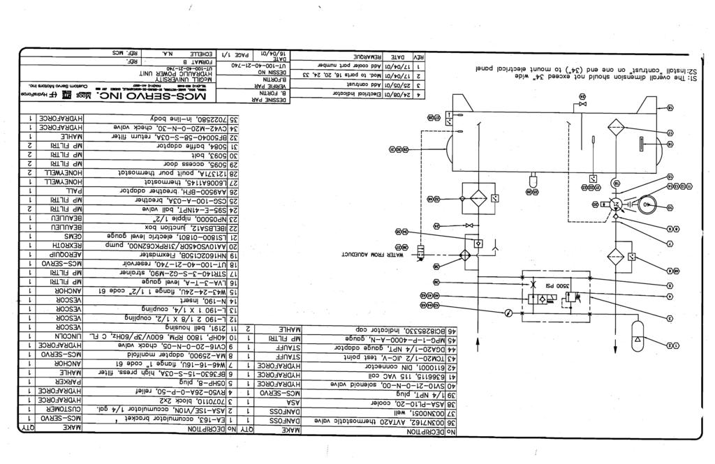
19 5. HYDRAULIC SCHEMATICS 19
20 HP020 Pressure FWD Flow 1 FWD Flow 2 Valve-X
21
22
23 6. TECHNICAL INFORMATION In this section, you will find all the information about the important parts and components of the hydraulic circuit. 23
Starting up hydraulic systems
 General / Installation A hydraulic system that operates economically, safely, and trouble-free requires careful planning, as well as proper installation and start-up. Conscientious maintenance has a considerable
Hydraulic Maintenance & Troubleshooting. Content - Norman Kronowitz Presenter Jim Trinkle
 Hydraulic Maintenance & Troubleshooting Content - Norman Kronowitz Presenter Jim Trinkle Introduction Welcome to the CMA/Flodyne/Hydradyne s Hydraulic Troubleshooting presentation. We will introduce many
FTM-L SERIES SINGLE OR TWIN DIRECT STEAM MIXER KETTLE COMPLETE WITH HYDRAULIC POWER TILT BRIDGE PARTS AND SERVICE MANUAL
 FTM-L SERIES SINGLE OR TWIN DIRECT STEAM MIXER KETTLE COMPLETE WITH HYDRAULIC POWER TILT BRIDGE PARTS AND SERVICE MANUAL EFFECTIVE SEPTEMBER 19, 2014 Superseding All Previous Parts Lists. The Company reserves
WARCO CHEMAG SERIES GH FILTERS
 WARCO CHEMAG SERIES GH FILTERS High Performance Pleated & Bag Type Filtration Systems INSTALLATION, OPERATION, AND MAINTENANCE INSTRUCTIONS Thank you for your purchase of a WARCO Series GH Filtration System.
Troubleshooting the Transmission Hydraulic System
 Testing and Adjusting IT28F INTEGRATED TOOLCARRIER POWER TRAIN Testing And Adjusting Introduction Reference: For Specifications with illustrations, refer to SENR5974, IT28F Integrated Toolcarrier Power
Table 6-1. Problems and solutions with pump operations. No Fluid Delivery
 Table 6-1. and solutions with pump operations No Fluid Delivery Fluid level in the reservoir is low. Oil intake pipe or inlet filter is plugged. Air leak in the inlet line prevents priming or causes noise
NECO Pumping Systems
 INSTALLATION OPERATION & MAINTENANCE INSTRUCTIONS For Your NECO Pumping Systems Fuel Oil Transfer System THIS COMPLETELY ASSEMBLED, TESTED, PACKAGED SYSTEM IS OF THE HIGHEST QUALITY AND DESIGN. TO OBTAIN
Standard Power Units Start-Up and Maintenance
 Standard Power Units Start-Up and Maintenance Value-Pak System-Pak System Pak-Plus Low-Pak System-Center System-L System-Overhead Table of Contents General Information....................................................................
Section 6.1. Implement Circuit - General System. General: TF Configuration TB Configurations Implement Control Valve:
 Section 6.1 Implement Circuit - General System General: TF Configuration... 6.1.3 TB Configurations... 6.1.5 Implement Pump Breakdown... 6.1.6 Operational Description: General... 6.1.7 Compensator Control...
TECHNICAL PAPER 1002 FT. WORTH, TEXAS REPORT X ORDER
 I. REFERENCE: 1 30 [1] Snow Engineering Co. Drawing 80504 Sheet 21, Hydraulic Schematic [2] Snow Engineering Co. Drawing 60445, Sheet 21 Control Logic Flow Chart [3] Snow Engineering Co. Drawing 80577,
Routine Compressor Maintenance
 Establishing a regular, well-organized maintenance program and strictly following it is critical to maintaining the performance of a compressed air system. One person should be given the responsibility
Fluid Maintenance. The hydraulic oil performs four functions in the hydraulic system:
 The hydraulic oil performs four functions in the hydraulic system: Transmits Energy Coolant Lubricant Sealant Viscosity Viscosity is the rating of the oil thickness or resistance to flow. Viscosity is
Medium and high pressure pumps
 Screw pumps Medium and high pressure pumps Installation and Start-up Instruction This instruction is valid for all standard high pressure pumps: E4, D4 and D6 Contents Page Pump identification 2 Installation
(770) Turning Parts Changers Into TROUBLESHOOTERS!
 Turning Parts Changers Into TROUBLESHOOTERS!") Hydraulic Consulting, Inc. Turning Parts Changers Into TROUBLESHOOTERS! This e-book manual is your customized troubleshooting manual in Adobe Acrobat Portable Document File (PDF) format. It requires the
Hydraulic Consulting, Inc. Turning Parts Changers Into TROUBLESHOOTERS! This e-book manual is your customized troubleshooting manual in Adobe Acrobat Portable Document File (PDF) format. It requires the
CIRCLE SEAL CONTROLS
 CIRCLE SEAL CONTROLS ATKOMATIC SOLENOID VALVES INSTALLATION, MAINTENANCE, AND OPERATION INSTRUCTIONS 3000 SERIES Bronze, Normally Closed, Direct Lift Installation Instructions WARNING: These instructions
INSTALLATION, OPERATION AND MAINTENANCE TECHNICAL MANUAL
 ISO 9001:2008 Via Renata Bianchi, 12 16152 Genova ITALY Tel. +39.01.6017016 Fax. +39-010-601-6021 www.tecnidro.com s INDEX 1. Introduction 1.1 Premise 1.2 Generality 1.3 Principle of operation 2. INSTALLATION
XCITE Owner s Manual. Reso-not TM Damping System XCITE 1502C HYDRAULIC POWER SUPPLY
 Reso-not TM Damping System XCITE Owner s Manual 1502C HYDRAULIC POWER SUPPLY Xcite Systems Corporation 675 Cincinnati RDS Batavia - 1 Pike Cincinnati, Ohio 45245 Tel: (239) 980-9093 Fax: (239) 985-0074
k. Components not properly adjusted. Refer to machine technical manual for proper adjustment of components.
 General Troubleshooting Charts General Troubleshooting Charts Use the charts on the following pages to help in listing all the possible causes of trouble when you begin diagnosing and testing of a machine.
GPM Hydraulic Consulting, Inc. P.O. Box 689. Social Circle, GA Hydraulic Consulting, Inc
 Hydraulic Consulting, Inc This special promotional CD is to demonstrate how your hydraulic troubleshooting manual can be ordered as an Adobe Acrobat ebook. It can be installed on any computer with the
TWO-STAGE HYDRAULIC PUMP. RWP55-IBT-Air
 ORIGINAL INSTRUCTIONS Form No.1000458 5 SPX Corporation 5885 11th Street Rockford, IL 61109-3699 USA Tech. Services: (800) 477-8326 Fax: (800) 765-8326 Order Entry: (800) 541-1418 Fax: (800) 288-7031 Internet
Hydraulic and Commissioning Mannual Module 2A
 Hydraulic and Commissioning Mannual Module 2A 2/7 Table of Contents 1 Features 3 2 Hydraulic Commissioning 3 2.1 Functional Purpose 3 2.2 System Description 3 3 Hydraulic Commissioning Instructions 4 4
US - UP2/OIL 12V US - UP2/OIL 24V
 SELF PRIMING ELECTRIC PUMP FOR TRANSFERRING LUBRICATING OILS OR VISCOUS FLUIDS INSTRUCTIONS FOR USE 164 220 12-US - UP2/OIL 12V 164 220 13-US - UP2/OIL 24V 15/05/14 Rev.02 A PRODUCT DESCRIPTION Self-priming
OPERATION AND PARTS MANUAL
 OPERATION AND PARTS MANUAL MODEL NUMBER : PART NUMBER : TAP- IN KIT 5100-5151 BAYNE MACHINE WORKS, INC. PHONE: (864) 288-3877 910 FORK SHOALS ROAD TOLL FREE: (800) 535-2671 GREENVILLE S.C., 29605 FAX:
MP18/SIC & SIO Stacking Valve System Technical Information Manual
 Electric Drives and Controls Hydraulics Linear Motion and Assembly Technologies Pneumatics Service MP18/SIC & SIO Stacking Valve System Technical Information Manual The Drive & Control Company Copyright
NECO Pumping Systems
 INSTALLATION OPERATION & MAINTENANCE INSTRUCTIONS For Your NECO Pumping Systems PACKAGED CIRCULATING SYSTEM THIS COMPLETELY ASSEMBLED, TESTED, PACKAGED CIRCULATING SYSTEM IS OF THE HIGHEST QUALITY AND
INSTALLATION, OPERATION AND MAINTENANCE INSTRUCTIONS
 INSTALLATION, OPERATION AND MAINTENANCE INSTRUCTIONS Contents Section 1. General Observations... 2 2. Operation... 4 3. Control During Operation... 5 4. Trouble Shooting... 6 5. Maintenance... 7 Please
Deister Machine Company, Inc. Heavy Duty System Saver Operating Instructions
 June 8, 2005 Deister Machine Company, Inc. Heavy Duty System Saver Operating Instructions Equipment Description- The Deister System Saver is a portable hand held oil pumping and filtration unit designed
CONTENTS. EMERGENCY PUMP USE Electric Pump...H-3 Manual Pump...H-5
 Anchor Applicator Model BAAM HYDRAULIC CONTENTS EMERGENCY PUMP USE Electric Pump...H-3 Manual Pump...H-5 PRESSURE SETTINGS General Settings and Locations of Manifolds...H-5 Main System Pressure and Relief...H-6
Operation & Service Manual
 Operation & Service Manual Model: 5010 Hydraulic Power Unit 05/2004 - Rev. 01 Includes Illustrated Parts Lists 1740 Eber Rd Tronair, Inc. Phone: (419) 866-6301 Holland, OH 43528-9794 www.tronair.com 800-426-6301
Pneumatic High-Viscosity Filtration System Instruction Manual
 Pneumatic High-Viscosity Filtration System Instruction Manual P/N: 61512 05/17 1 2 Pneumatic High Viscosity Filtration Systems PN: 61512 14 April, 2009 rev A 36933 Pneumatic Hand Cart HV Filtration System
Hydraulic Pump Troubleshooting P & BDP Series Models
 Hydraulic Pump Troubleshooting P & BDP Series Models Hydraulic Pump damage can cause traction circuit failures and problematic hydraulic system contamination. Performance problems such as weak traction
Section 5: Hydraulic Pump SAUER DANFOSS. SERVICE MANUAL Property of American Airlines. 5-5 Page 1 September 09 HYDRAULIC PUMP
 Section 5: Hydraulic Pump SAUER DANFOSS SERVICE MANUAL HYDRAULIC PUMP 5-5 Page 1 September 09 THIS PAGE INTENTIONALLY LEFT BLANK Series 45 Frame G and H Open Circuit Axial Piston Pumps Service Manual Introduction
Track Drive Circuit - General System. Simplified Travel Circuit Diagrams: Neutral Controls Forward Travel Reverse Travel
 Section 7.1 Track Drive Circuit - General System Simplified Travel Circuit Diagrams: Neutral Controls... 7.1.2 Forward Travel... 7.1.4 Reverse Travel... 7.1.5 General... 7.1.3 Track Drive Circuit: General...
PUMP SCPD 56/26 DIN BY-PASS
 GB INSTRUCTION MANUAL THANK YOU FOR CHOOSING SUNFAB You have chosen SCPD 56/26 DIN, a dual flow pump with differentiated flow suitable for combination vehicles with high power take off ratio and high output
Single Stage Rotary Vane Vacuum Pump Installation and Operation Manual RX-10 RX-21 RX-25
 V acuum Pumps Single Stage Rotary Vane Vacuum Pump Installation and Operation Manual RX-10 RX-21 RX-25 www.republicsales.com Revised 10.14 2014 Republic Sales & Manufacturing Single Stage Rotary Vane Vacuum
WALKIE HIGH LIFT HYDRAULIC SYSTEM
 WALKIE HIGH LIFT HYDRAULIC SYSTEM W30-40ZA [B453]; W20-30ZR [B455]; W25-30-40ZC [B454] PART NO. 1524251 2000 SRM 1025 SAFETY PRECAUTIONS MAINTENANCE AND REPAIR When lifting parts or assemblies, make sure
INSTRUCTION MANUAL INDUSTRIAL PERISTALTIC PUMPS MODEL RBT-70
 INSTRUCTION MANUAL INDUSTRIAL PERISTALTIC PUMPS MODEL RBT-70 This manual forms an integral part of the pump and must accompany it until its demolition. The series FMP peristaltic pump is a machine destined
Excellence In Fluid Control Since 1975
 Excellence In Fluid Control Since 1975 Company Profile HVC Engineering & Technologies, is engaged in the manufacturing of Hydraulic Valves and Systems since 1975; the Industrial Hydraulic Valves & Systems
STEERING HYDRAULICS The steering system is a flow amplified, load sensing, hydraulics arrangement.
 STEERING HYDRAULICS 116821 The steering system is a flow amplified, load sensing, hydraulics arrangement. When the steering wheel is turned, the Steering Metering Pump meters an oil volume proportional
TABLE OF CONTENTS. 1. Before You Begin 3 Disclaimer 3 What Is Included 3 Optional Accessories 3 Unpacking Instructions 3 Claims 3 Contact Us 3
 Page 1 of 25 TABLE OF CONTENTS 1. Before You Begin 3 Disclaimer 3 What Is Included 3 Optional Accessories 3 Unpacking Instructions 3 Claims 3 Contact Us 3 2. Safety Information 4 Safety Notes 4 Rules for
Operator's Manual. Models (¾") (1") (1½ ) (2 ) (3") (4") (6") (8")
 (1) (1½ ) (2 ) (3) (4) (6) (8)") OdisMatic Hydraulic Filter Series 851 Operator's Manual Models 85107 (¾") 85101 (1") 85115 (1½ ) 85102 (2 ) 85103 (3") 85104 (4") 85106 (6") 85108 (8") Content 1. Technical Specifications. 2. Materials.
OdisMatic Hydraulic Filter Series 851 Operator's Manual Models 85107 (¾") 85101 (1") 85115 (1½ ) 85102 (2 ) 85103 (3") 85104 (4") 85106 (6") 85108 (8") Content 1. Technical Specifications. 2. Materials.
Check Valves Check Valves are the simplest form of directional control valves, but they can also be used as pressure controls.
 Check Valves Check Valves are the simplest form of directional control valves, but they can also be used as pressure controls. Standard Check Valve The standard check valve permits free flow in one direction
Installation, Operation, and Maintenance Manual Outdoor Glycol Feed System JWOP /055/100
 Installation, Operation, and Maintenance Manual Outdoor Glycol Feed System JWOP-53-030/055/100 Rev. 1 3/21/11 K.G. Type - John Wood #JWOP-53-030/055/100, Outdoor Glycol Feed System Capacity 30/55/100 Gallons
Hydrostatic Drive. 1. Main Pump. Hydrostatic Drive
 Hydrostatic Drive The Hydrostatic drive is used to drive a hydraulic motor at variable speed. A bi-directional, variable displacement pump controls the direction and speed of the hydraulic motor. This
HGV VARIABLE HYDRAULIC GENERATOR SYSTEMS
 Internet: http://www.dynaset.com 00 HGV VARIABLE HYDRAULIC GENERATOR SYSTEMS INSTRUCTIONS Internet: http://www.dynaset.com 00 GENERAL NOTES DYNASET variable hydraulic generator system, especially designed
Single Stage Rotary Vane Vacuum Pump Installation and Operation Manual RX-40 RX-63 RX-100
 V acuum Pumps Single Stage Rotary Vane Vacuum Pump Installation and Operation Manual RX-40 RX-63 RX-100 www.republicsales.com Revised 02.15 2015 Republic Sales & Manufacturing Single Stage Rotary Vane
DP5 Pump. 5:1, Air-operated, Heavy Duty, Oil. General. Operation. Technical Data. Installation R1 09/10
 DP5 Pump 5:1, Air-operated, Heavy Duty, Oil General The DP5 Pump is a compressed air-operated reciprocating piston medium pressure pump. These pumps are suitable for distribution of all types of light
MP18 Stacking Valve System Technical Information Manual
 Electric Drives and Controls Hydraulics Linear Motion and Assembly Technologies Pneumatics Service MP18 Stacking Valve System Technical Information Manual The Drive & Control Company Copyright 1996 Bosch
Flow Control Valve IOM 770-U
 IOM 770-U Flow Control Valve (Sizes 1½-14"; DN40-350) Description The Model 770-U Flow Control Valve is a hydraulically operated, diaphragm actuated, control valve that maintains pre-set maximum flow,
Servo and Proportional Valves
 Servo and Proportional Valves Servo and proportional valves are used to precisely control the position or speed of an actuator. The valves are different internally but perform the same function. A servo
Troubleshooting The Transmission Hydraulic System
 416B, 426B, 428B, 436B, & 438B BACKHOE LOADERS TRANSMISSION Testing And Adjusting Troubleshooting The Transmission Hydraulic System Make reference to the following warning and pressure tap locations for
Instruction manual. Installation requirements. Power Take-Off. Pump mounting: Spline shaft DIN 5462 / ISO 14. Mounting flange ISO 7653-D.
 GB PUMP SCPD 76/76 DIN Instruction manual Thank you for choosing Sunfab You have chosen SCPD 76/76, a dual flow pump with the highest displacement-to-size-ratio on the market. It can effectively be directly
ARKAL SCREEN LINE H - SERIES Hydraulically Operated Self-Cleaning Screen Filter SERVICE & MAINTENANCE MANUAL
 ARKAL SCREEN LINE H - SERIES Hydraulically Operated Self-Cleaning Screen Filter SERVICE & MAINTENANCE MANUAL Table of Contents Subject Page No. Introduction... 2 Safety Instructions... 3 Description &
Section 7.1. Wheel Drive Circuit - General System
 Section 7.1 Wheel Drive Circuit - General System Simplified Travel Circuit Diagrams: Neutral Controls... 7.1.2 Forward Travel... 7.1.4 Reverse Travel... 7.1.5 General... 7.1.3 Wheel Drive Circuit: General...
ACTO 400 to MAINTENANCE
 Maintenance 8506.84/2-EN ACTO 400 to 1600 - MAINTENANCE INSTALLATION MAINTENANCE 1- General overview 2- Tooling 3- Installation 4- Draining Procedure and Hydraulic remote control 5- Adjustment of end stops
HYDRAULIC SYSTEM, ISL-07
 SECTION 09-304.295 09-304.295/ 1 GENERAL DESCRIPTION 7 1 This system uses hydraulic power to operate a fan that forces outside air into the radiator located on the left-hand side at the rear of the bus.
SECTION HYDRAULIC SYSTEM
 09-304.06/ 1 SECTION 09-304.06 GENERAL DESCRIPTION 7 1 This system uses hydraulic power to operate a fan that forces outside air into the radiator located on the left-hand side at the rear of the bus.
To ensure proper installation, digital pictures with contact information to before startup.
 Check List for Optimal Filter Performance? There should be no back-pressure on the flush line. A 1 valve should have a 2 waste line, and 2 valve should have a 3 waste line. Do not use rubber hosing or
Low Profile J Series Power Unit with Vane Pump
 Low Profile J Series Power Unit with Vane Pump READ ALL INSTRUCTIONS CAREFULLY BEFORE ATTEMPTING TO ASSEMBLE, INSTALL, OPERATE OR MAINTAIN THE PRODUCT DESCRIBED. PROTECT YOURSELF AND OTHERS BY OBSERVING
TIN KNOCKER TK H1652 Hydraulic Shear
 TIN KNOCKER TK H1652 Hydraulic Shear INSTRUCTIONS & PARTS DIAGRAM TAAG INDUSTRIES CORP. 1550 SIMPSON WAY, ESCONDIDO, CA 92029 Tel: (800) 640-0746 Fax: (760) 727-9948 Website: www.tinknocker.com Email:
Arctic Equipment Manufacturing Corporation M3551 Hydraulic Power Unit. Table of Contents
 Arctic Equipment Manufacturing Corporation M3551 Hydraulic Power Unit Table of Contents General Information...2 Hydraulic Information Diagrams...7 Hydraulic and Electrical Installation...10 Parts List...11
TC Series Cooling Systems
 TC Series Cooling Systems Table of Contents Table of Contents...1 List of Figures...1 Safety...2 Introduction...2 General Specifications...2 Types of Coolant...2 Routine Maintenance...2 Surge Tank Coolant
Ideal Installation. I & M Mark 67 (1/2 6 ) Control Line. Installation & Maintenance Instructions for Mark 67 Pressure Regulators
 Control Line. Installation & Maintenance Instructions for Mark 67 Pressure Regulators") I & M Mark (/ ) 0 Wasson Road Cincinnati, OH 0 USA Phone --00 Fax -8-00 info@richardsind.com www.jordanvalve.com Installation & Maintenance Instructions for Mark Pressure Regulators Warning: Jordan Valve
I & M Mark (/ ) 0 Wasson Road Cincinnati, OH 0 USA Phone --00 Fax -8-00 info@richardsind.com www.jordanvalve.com Installation & Maintenance Instructions for Mark Pressure Regulators Warning: Jordan Valve
What is hydraulic power pack?
 What is hydraulic power pack? What are the hydraulic power pack applications? Mobile hydraulics applications increasing so much with hydraulic power pack recently. Such as, dump trailers, electric sanitation
Q= C. v P S Refer to Table 1 for part numbers and shipping weights. Accessories: Table 1: Valve Part Numbers and Specifications
 1 of 9 1. DESCRIPTION The Viking Flow Control Valve is a quick opening, differential diaphragm flood valve with a spring loaded floating clapper. The Flow Control Valve can be used to facilitate manual
OFX7 Operating Maintenance and Troubleshooting Manual L-4219
 OFX7 Operating Maintenance and Troubleshooting Manual L-4219 L-2999 Created 9.2012 User Manual OFX7 L-4219 - Table of Contents - Preface. 4 Customer Service. 4 Modifications to the Product 4 Warranty.
Technical Information for PVX Series Pumps
 Technical Information for PVX Series Pumps TM 604 PROGRESS DRIVE, HARTLAND, WI 53029 USA Phone: (262) 367-4299 FAX: (262) 367-5645 URL: www.hartmanncontrols.com E-mail: sales@hartmanncontrols.com PVX pumps
CIRCLE SEAL CONTROLS
 CIRCLE SEAL CONTROLS ATKOMATIC SOLENOID VALVES INSTALLATION, MAINTENANCE, AND OPERATION INSTRUCTIONS 13000 SERIES Stainless, Normally Closed, Direct Lift, 3-Way Valve Installation Instructions WARNING:
Before you go through this booklet, we request you to go through the following general instruction before commissioning your hydraulic systems.
 Hello, We are proud to be on your suppliers list. During few years we came to know that most of our customers are satisfied by Yuken Hydraulic Products but some of our customers had minor problems and
DP3 Pump. 3:1, Air-operated, Oil. General. Operation. Technical Data. Installation R0 10/09. 35a 35b 35c
 DP3 Pump 3:1, Air-operated, Oil General The DP3 Pump is a compressed air-operated piston reciprocating medium pressure pump. Suitable for medium flow transfer of high viscosity lubricants and for oil delivery
Operation & Service Manual
 Operation & Service Manual Model: 5B20 Hydraulic Power Unit 07/2011 - Rev. 06 Includes Illustrated Parts Lists 1740 Eber Rd Tronair, Inc. Phone: (419) 866-6301 Holland, OH 43528-9794 www.tronair.com 800-426-6301
Fuel Metering System Component Description
 1999 Chevrolet/Geo Tahoe - 4WD Fuel Metering System Component Description Purpose The function of the fuel metering system is to deliver the correct amount of fuel to the engine under all operating conditions.
Operating instructions Form no safety definitions
 Operating instructions Form no. 1000437 safety definitions safety symbols are used to identify any action or lack of action that can cause personal injury. Your reading and understanding of these safety
Operating Manual for Rotary Gear Pumps CMI, S.A. (Mendaro, Guipuzkoa, Spain)
") Operating Manual for Rotary Gear Pumps CMI, S.A. (Mendaro, Guipuzkoa, Spain) Pre-Installation 1. Choose a location that is easily accessible for pump servicing. Ensure adequate electrical service is available.
Operating Manual for Rotary Gear Pumps CMI, S.A. (Mendaro, Guipuzkoa, Spain) Pre-Installation 1. Choose a location that is easily accessible for pump servicing. Ensure adequate electrical service is available.
Installation, Operating, Maintenance and Safety Instructions for CW332 Pressurised water system for boats 24 volt d.c.
 24V DC-CW332 DOC531/11 Installation, Operating, Maintenance and Safety Instructions for CW332 Pressurised water system for boats 24 volt d.c. To obtain the best performance from your Pressurised water
TROUBLESHOOTING TABLE
 TROUBLESHOOTING TABLE TROUBLESHOOTING GUIDE GLOSARY OF TERMS VANE PUMPS NO FLOW, NO PRESSURE A) Is the pump rotating? a-1) Check if the coupling is rotating. If not, check the rotation of the electric
WALKIE HYDRAULIC SYSTEMS
 WALKIE HYDRAULIC SYSTEMS B60Z [A230]; B80Z [A233]; C60Z [A478]; C80Z [A479]; W60Z [A231]; W65Z [A229]; W80Z [A234]; B60Z AC [B230]; B80Z AC [B233]; C60Z AC [B478]; C80Z AC [B479] PART NO. 1500201 1900
Exercise 3-1. Basic Hydraulic Circuit EXERCISE OBJECTIVE DISCUSSION OUTLINE DISCUSSION. Complete hydraulic circuit
 Exercise 3-1 Basic Hydraulic Circuit EXERCISE OBJECTIVE When you have completed this exercise, you will be familiar with the hydraulic schematic and components of the nacelle trainer. You will identify
PT, PTS & PTP Series Pump/Reservoirs
 PT, PTS & PTP Series Pump/Reservoirs Installation, Operation and Maintenance Manual Table of Contents FOREWORD... 1 INSTALLATION... 1 RECEIVING INSPECTION... 1 RIGGING, HANDLING, AND LOCATING EQUIPMENT...
Module 5: Valves. CDX Diesel Hydraulics. Terms and Definitions. Categories of Valves. Types of Pressure Control Valves
 Terms and Definitions Categories of Valves Types of Pressure Control Valves Types and Operation of Pressure Relief Valves Operation of an Unloading Valve Operation of a Sequencing Valve Operation of a
Val-Matic Air / Oil Hydraulic Panel Pump Control System. Operation, Maintenance and Installation Manual
 Manual No. 5AOP-OM1-2 Val-Matic Air / Oil Hydraulic Panel Pump Control System Operation, Maintenance and Installation Manual INTRODUCTION... 1 RECEIVING AND STORAGE... 1 DESCRIPTION OF OPERATION... 1 INSTALLATION...
On Board Diagnostics II Diesel PCED
 Page 1 of 19 1999 PCED On Board Diagnostics II Diesel SECTION 4: Diagnostic Subroutines Performance Diagnostic Procedures Page 2 of 19 Page 3 of 19 Page 4 of 19 Page 5 of 19 1. Visual Engine/Chassis Inspection
High Performance Vacuum Pump Model 15120A/15121A Operating Manual...
 High Performance Vacuum Pump Model 15120A/15121A Operating Manual... Operating Manual Table of Contents Warnings...1 CoolTech high performance vacuum pumps...1 Pump components...2 Before using your vacuum
Installation Operation & Maintenance Manual. Oil-Free (Dry) Rotary Vane Vacuum Pump Systems
 Rotary Vane Vacuum Pump Systems") Installation Operation & Maintenance Manual Oil-Free (Dry) Rotary Vane Vacuum Pump Systems Part No. 9983-0000-S07 / November 2018 OIL-FREE (DRY) ROTARY VANE VACUUM PUMP SYSTEMS TABLE OF CONTENTS CUSTOMER
Installation Operation & Maintenance Manual Oil-Free (Dry) Rotary Vane Vacuum Pump Systems Part No. 9983-0000-S07 / November 2018 OIL-FREE (DRY) ROTARY VANE VACUUM PUMP SYSTEMS TABLE OF CONTENTS CUSTOMER
Fuel System (Central SFI)
") Page 1 of 6 1997 GMC Truck GMC K Pickup - 4WD Chevy Pickup, GMC Pickup, Suburban, Tahoe, Yukon (VIN C/K) Service Manual Engine Engine Controls - 5.0L, 5.7L, and 7.4L Description and Operation Document
Page 1 of 6 1997 GMC Truck GMC K Pickup - 4WD Chevy Pickup, GMC Pickup, Suburban, Tahoe, Yukon (VIN C/K) Service Manual Engine Engine Controls - 5.0L, 5.7L, and 7.4L Description and Operation Document
Hydraulic Immediate Need Power Pack
 Safety, Operation, and Maintenance Manual WARNING Improper use of this tool can result in serious bodily injury This manual contains important information about product function and safety. Please read
OCTOPUS SELECTION & INSTALLATION GUIDE
 OCTOPUS SELECTION & INSTALLATION GUIDE CRB SERIES CONTINUOUS RUNNING PUMPSET A. GENERAL DESCRIPTION: Octopus CRB pumpsets are heavy duty, continuously running, electric motor driven pumps which are used
Installation Operation and Maintenance Manual
 Installation Operation and Maintenance Manual Lubricated high vacuum rotary vane pumps SERIAL NO.: June 2006/5 LUBRICATED HIGH VACUUM ROTARY VANE PUMPS TABLE OF CONTENTS INTRODUCTION 3 Safety 3 STORAGE
INSTRUCTIONS FOR HYDRAULIC FILTER UNITS NEF PPE SOUTH
 INSTRUCTIONS FOR HYDRAULIC FILTER UNITS NEF11-610-603 MM4-610-603 Made in the U.S.A. by Plastic Process Equipment, Inc. copyright 2006 RECEIVING: Please thoroughly inspect your Hydraulic Oil Filtration
Troubleshooting, Service Tips, And Major Improvements For Hydrostatic Transmissions (Special Edition){3200}
{3200}") Page 1 of 75 Troubleshooting, Service Tips, And Major Improvements For Hydrostatic Transmissions (Special Edition){3200} 943, 953, 963, 973 Loaders Introduction The hydrostatic transmissions used in 943,
Page 1 of 75 Troubleshooting, Service Tips, And Major Improvements For Hydrostatic Transmissions (Special Edition){3200} 943, 953, 963, 973 Loaders Introduction The hydrostatic transmissions used in 943,
MODEL 25-OM-10-C & 25-OA-10-C HYDRAULIC BOOSTER
 SPX Corporation 5885 11th Street Rockford, IL 61109-3699 USA Internet Address: http://www.powerteam.com Tech. Services: (800) 477-8326 Fax: (800) 765-8326 Order Entry: (800) 541-1418 Fax: (800) 288-7031
Table of Contents.
 3551 Table of Contents Operating Information...2 Hydraulic Information Diagrams...7 Hydraulic and Electrical Installation...10 Parts List...11 Troubleshooting...15 Page 1 M3551 M3551 Operating Information
HYDRAULIC STEERING MANIFOLD HM260 TABLE OF CONTENTS. 1. GENERAL INFORMATION... p TECHNICAL SPECIFICATIONS... p. 01
 HYDRAULIC STEERING MANIFOLD HM260 TABLE OF CONTENTS 1. GENERAL INFORMATION... p. 01 2. TECHNICAL SPECIFICATIONS... p. 01 3. HYDRAULIC MANIFOLD... p. 01 4. INSTALLATION... p. 01 4.1 Mechanical 4.2 Hydraulic
Portable Filter Carts Models 5MF and 10MF
 s Models 5MF and 10MF 161 Applications for Parker Filter Carts Filtering new fluid before putting into service Transferring fluid from drums or storage tanks to system reservoirs Conditioning fluid that
Lecture 32 MAINTENANCE OF FLUID POWER SYSTEMS
 Lecture 32 MAINTENANCE OF FLUID POWER SYSTEMS Learning Objectives Upon completion of this chapter, the student should be able to: List the most common causes of hydraulic system breakdown. Explain the
Heavy duty slurry pumps
 USERS MANUAL Heavy duty slurry pumps TOYO PUMPS EUROPE Edition 27.07.2007 SAFETY INSTRUCTIONS TOYO PUMPS EUROPE Users manual for Toyo pumps type «DP..-6 30~40HP» This users manual will help you to maintain
PROMAG SR SERIES SEAL-LESS CENTRIFUGAL PUMPS
 PROMAG SR SERIES SEAL-LESS CENTRIFUGAL PUMPS INSTALLATION, OPERATION, AND MAINTENANCE INSTRUCTIONS TO OBTAIN THE BEST PERFORMANCE FROM YOUR PROMAG SR PUMP, PLEASE READ THE MANUAL CAREFULLY. Failure to
Dodge Cool Lube 2 for Sleevoil Pillow Blocks Part Numbers , , ,
 Dodge Cool Lube for Sleevoil Pillow Blocks Part Numbers 063487, 063488, 07889, 07890 These instructions must be read thoroughly before installation or operation. This instruction manual was accurate at
SERIES PC INSTRUCTION AND OPERATION MANUAL
 MEGGA SERIES PC INSTRUCTION AND OPERATION MANUAL Models PCT and PCF Close-coupled and frame-mounted single-stage horizontal end-suction pumps. WARNING: Read this manual before installing or operating this