TABLE OF CONTENTS. 1. Before You Begin 3 Disclaimer 3 What Is Included 3 Optional Accessories 3 Unpacking Instructions 3 Claims 3 Contact Us 3
|
|
|
- Mitchell Hubbard
- 5 years ago
- Views:
Transcription


1 Page 1 of 25
2 TABLE OF CONTENTS 1. Before You Begin 3 Disclaimer 3 What Is Included 3 Optional Accessories 3 Unpacking Instructions 3 Claims 3 Contact Us 3 2. Safety Information 4 Safety Notes 4 Rules for Safe Hydraulic Operation 4 Three Common Hydraulic System Hazards 4 Ways to Prevent Hazards from Occurring 4 Safety Locks 5 Manual Cylinder Lock 6 3. Setup 7 Assembly 7 Recommended Tools 7 4. Operation Instructions 11 Pre-Operation Maintenance 11 Operation Instructions Technical Information 13 Product Maintenance Technical Specifications 14 Specifications 14 Replacement Parts Hydraulic Information (optional) 19 General System Information 19 Hydraulic Pump Information 19 Radio Remote System Information 19 Hydraulic Power Unit Diagram Trouble Shooting and FAQs 20 Page 2 of 25
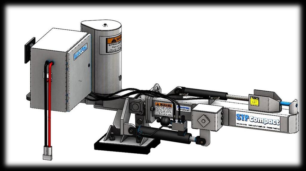
3 1. Before You Begin Disclaimer The information and specifications contained in this document are subject to change without notice. Safe-T-Pull Inc. assumes no responsibility or liability for any errors or omissions that may appear in this manual. Safe-T-Pull Inc. reserves the right to update the existing document or to create a new document to correct any errors or omissions. You can receive the latest version of this document from Safe-T-Pull Inc. by calling your local dealer during their business hours. What Is Included Puller Tube Assembly Swivel Assembly Spring Tongue Smart Lift Cylinder Safe-T-Pull Compact User s Manual Manual cylinder lock (FP-173) 1 Mast lock pin (XP-210) Optional Accessories Hydraulic Power Unit (XP-008) Bumper (CM-005) Safe-T-Pull Receiver (model dependent) Camera System (XP-020) Unpacking Instructions Immediately upon receipt, carefully unpack the product and check the packaging to make sure you have received all the parts indicated above and that they are in good condition. Claims If the packaging or the material inside the packaging (the product and included accessories) appear damaged from shipping, or show signs of mishandling, upon receipt notify the carrier immediately, not Safe-T-Pull Inc. Failure to do so in a timely manner may invalidate your claim with the carrier. In addition, keep the container and all the packing material for inspection. For other issues such as missing components or parts, damage not related to shipping, or concealed damage, file a claim with Safe-T-Pull Inc. immediately after receiving the merchandise. Contact Us sales@safe-t-pull.net Mail - Safe-T-Pull P.O. Box 94 Park River, ND Web Page 3 of 25
4 2. Safety Information Please read the following safety notes carefully before working with the product. These notes include important safety information about installation, usage, and maintenance. Safety Notes All personnel working on, with, or near a Safe-T-Pull Compact must wear safety toed shoes, safety glasses, reflective safety vest, protective gloves, and hard hat. The Safe-T-Pull Compact may raise or lower unexpectedly. When servicing the Safe-T-Pull Compact be sure the pulling vehicle is OFF and the puller arm is in the lowered position. When traveling on public roads or during extended periods of storage, install the manual cylinder lock. This will prevent the puller arm from accidentally lowering. Mast lock pins should also be installed. WARNING: Contact with the bumper will cause your puller arm to fold down if all locks are not installed. See the safety lock section of this document for more information. Rules for safe hydraulic operation Park hydraulic machinery where children cannot reach it. If your pulling vehicle has hydraulic flow control capabilities, (usually measured in GPM) decrease the flow to the minimum amount required to operate the Safe-T-Pull Compact Block the Safe-T-Pull Compact when you must work on the system while raised; do not rely solely on the hydraulic lift. Avoid servicing the hydraulic system while the machine engine is running. Do not remove cylinders until the Safe-T-Pull Compact is resting on the ground or securely on safety stands or blocks; shut off engine. Before disconnecting hydraulic hoses, relieve all hydraulic pressure. Be sure all hose connections are tight and hoses are not damaged. Use a non-volatile cleaning solvent to wash parts. Three common hydraulic system hazards Burns from very hot, high pressure fluid. Injuries and illness from flailing hydraulic lines. Hydraulic fluid injection into the body. Ways to prevent hazards from occurring When attempting to detect pinhole leaks in hydraulic hoses run a piece of cardboard or wood along the hose. NEVER touch hydraulic hoses when they are under pressure. Never connect a low pressure hose, cylinder, or other aftermarket equipment to the Safe-T- Pull Compact. Ensure all hydraulic components are in proper working condition on the pulling vehicle. Periodically check for oil leaks and worn hoses. Keep contaminants from hydraulic oil and replace filters regularly. Lubricate cylinder rods with protective lubricant to avoid rusting. Page 4 of 25

5 Safety Locks As a safety feature, Safe-T-Pull Compact s come equipped with manual puller arm locks (CP- 006). The Safe-T-Pull Compact may be locked into the raised postion. Raised Position When the puller arm is raised all of the way up, a pin may be installed into the top hole position to keep it from lowering. WARNING: These pins may NOT stop the puller arm from being raised or lowered hydraulically. Page 5 of 25

6 Manual Cylinder Lock As a safety feature, Safe-T-Pull Compacts come equipped with a Manual Cylinder Lock (FP-173). The Safe-T-Pull Compact may be locked upright. This is recommended whenever the puller arm is in the raised position for extended periods of time. The Manual Cylinder Lock can be installed by raising the puller arm all the way up and clipping the lock onto the cylinder ram with the included Retainer Clips (XP-210). Page 6 of 25
7 3. Setup Unpacking Instructions: Before discarding any packaging, be sure all included parts are accounted for. Remove all strapping and/or banding on the package. For claims please visit section 1 of this document. Assembly: If your Safe-T-Pull Compact has been palletized, assembly is required. After unpacking follow these steps to assemble your Safe-T-Pull Compact. Recommended Tools: Lifting device (fork lift, skid-steer, cherry picker) Chain or lifting strap Two ¾ wrenches or sockets Two 11/16 wrenches Two 1 1/8 wrenches or sockets One 1 1/2 wrench or socket One 1 7/16 wrench or socket WARNING: All lifting equipment must be rated for 1,000 pounds (453.5kg) or more! Step 1: Remove the swivel assembly by lifting it out of its stand using a lifting strap or chain. Note: Two ¾ wrenches or sockets required. Page 7 of 25


8 Step 2: Pin the Spring Tongue onto the Swivel Assembly. Bolt the pin into place with the included ½ bolt and nylock nut. Note: Two ¾ wrenches or sockets required. Step 3: Align the puller tube assembly and the tongue assembly as shown below. Slide the Spring Tongue into the Puller Tube Assembly. Page 8 of 25


9 Step 4: Bolt the tube and swivel assembly together with four included ¾ bolts, lock washers, and nuts. Note: Two 1 1/8 wrenches or sockets required Step 5: Using the provided pins, attach the Smart Lift Cylinder as shown below Page 9 of 25

10 Step 6: Install and bolt on the bumper with the included 1 bolt as shown below. Note: One 1 ½ wrench or socket and one 1 7/16 wrench or socket required. Note: The bumper may be installed directly to the receiver for use without a Safe-T-Pull WARNING: Contact with the bumper will cause your puller arm to fold down if all locks are not installed. See the safety lock section of the User s Manual for more information. Page 10 of 25
11 3. Operation Instructions Pre-Operation Maintenance Before every operation of your Safe-T-Pull Compact, an inspection and pre-operation maintenance should be done to ensure all components are in operating order: 1. Check hydraulic fluid in the hydraulic box reservoir to make sure levels are adequate. NOTE: Use only Aeroshell Fluid 4 hydraulic oil or your warranty will be void. 2. Check hydraulic hoses for cuts, cracks, pressure bubbles, or other damage. Replace if any signs of damage. WARNING: Steel braiding should NEVER be visible 3. Check hydraulic fittings for dents, cuts, leaks, or other signs of damage. Replace if any signs of damage. 4. Check to make sure all hydraulic hoses are securely fastened to their correct fittings. 5. Check to make sure all hydraulic cylinders pins are secured with correctly installed hitch clips and/or bolts. 6. Check power cables for cuts, cracks, corrosion, or other signs of damage. Replace if any signs of damage. 7. Check to make sure the power cable is connected correctly 8. Turn the power switch to the ON position 9. Power on the wireless remote 10. Cycle all cylinders to check for proper operation NOTE: Several cycles may be needed to fill the hydraulic lines NOTE: If your Safe-T-Pull Compact is being used continuously, pre-operation maintenance should be done before EVERY shift change or EVERY 12 hours, whichever comes first. Operating Instructions Hydraulic Power Unit Duty Cycle: The duty cycle for the 24 volt Safe-T-Pull Compact is three (3) minutes continuous run time with fifteen (15) minutes cool down. Cycling the hydraulic unit more than this will void your warranty. The duty cycle for the 12 volt Safe-T-Pull Compact is two and a half (2.5) minutes continuous run time with fifteen (15) minutes cool down. Cycling the hydraulic unit more than this will void your warranty. Excessive Heat and Noise Check During use, periodically check the hydraulic power unit for excessive heat and noise. If excessive heat and/or noise occurs refer to the hydraulic power unit troubleshooting section of this document. Page 11 of 25
 Once the Safe-T-Pull Compact s hook pin is directly under the Safe-T-Pull Truck Hitch pulling loop, raise the Safe-T-Pull Compact")
 to lock in the Truck Hitch. Remove the downed vehicle from its location to a suitable location. To hook up, back the Safe-T-Pull Pro under the Truck Hitch.")
12 Hooking up: Be sure ALL persons are clear of the operating area. With the Safe-T-Pull Compact arm in the lowered position (but not on the ground), back the pulling vehicle up to the stuck vehicle. (A decrease in engine RPMs may be necessary for more precise control) Once the Safe-T-Pull Compact s hook pin is directly under the Safe-T-Pull Truck Hitch pulling loop, raise the Safe-T-Pull Compact up (extend the lift cylinder) and into the Truck Hitch pulling loop. WARNING: For your safety NEVER use the Safe-T-Pull Compact for pulling on unauthorized products. Close the Pin (extend the Pin Cylinder) to lock in the Truck Hitch. Remove the downed vehicle from its location to a suitable location. To hook up, back the Safe-T-Pull Pro under the Truck Hitch. Lift the puller arm into the hitch loop and close the latch pin. Unhooking: Open the lock pin (retract the Pin Cylinder) Lower the Safe-T-Pull Compact (retract the lift cylinder). If there is tension between the hook pin of the puller and pulling loop of the Truck Hitch, the puller may not lower. In this case a decrease in ground speed by the pulling vehicle may be required to free the pulling arm from the Truck Hitch. Once the Safe-T-Pull Compact is clear of the Truck Hitch, raise the pulling arm up (extend the lift cylinder) to keep it from dragging on the ground. NOTE: Your warranty will be void if you use a Safe-T-Pull Compact with unauthorized products. To unhook, open the latch pin, lower the puller arm, and drive away. Page 12 of 25

13 4. Technical Information Product Maintenance For proper operation ensure the following equipment is in proper operating condition. Hydraulic system Check hydraulic fluid in the hydraulic box reservoir to make sure levels are adequate. NOTE: Use only Aeroshell Fluid 4 hydraulic oil or your warranty will be void. Check hydraulic hoses for cuts, cracks, pressure bubbles, or other damage. Replace if any signs of damage. CAUTION: Steel braiding should NEVER be visible Check hydraulic fittings for dents, cuts, leaks, or other signs of damage. Replace if any signs of damage. Check to make sure all hydraulic hoses are securely fastened to their correct fittings. Check to make sure all hydraulic cylinders pins are secured with correctly installed hitch clips and/or bolts. Change hydraulic filter after 40 hours of pump run time or once a year, whichever is first. Be sure to keep the interior of the hydraulic box clean and free of any dirt and debris. Grease Grease the three grease points as shown in the image below. Page 13 of 25
14 5. Technical Specifications Specifications Dimensions Length: 82 Width: 25 Height: 62 (dependent on options) Weight 700lbs (dependent on options) Hydraulic Power Source Optional Hydraulic Power Unit System Voltage 24v or 12V (Optional Hydraulic Power Unit) Max psi 3000 psi Page 14 of 25
15 Replacement Parts Contact your authorized dealer or manufacturer representative to order replacement parts. Page 15 of 25
16 Page 16 of 25
17 Page 17 of 25
18 Page 18 of 25
 Supply Voltage: 24v DC or 12v DC Power Draw: 68A @ 1200psi or 130A @ 1200psi Reservoir Oil Capacity: ~2 Gallons System Oil: Aero Shell 4 Work Port Connections:")
19 6. Hydraulic Information (optional) 6.1. General System Information (24v & 12v) Supply Voltage: 24v DC or 12v DC Power Draw: 1200psi or 1200psi Reservoir Oil Capacity: ~2 Gallons System Oil: Aero Shell 4 Work Port Connections: -6 JIC Male 6.2. Hydraulic Pump Information Hydraulic Flow: Approximately 1200psi Hydraulic Pressure: 1200psi Standard Setting Fluid Temperature Range: +32 to +158 F (Short Term -68 to +176 F for 10 Minutes Max) 6.3. Radio Remote System Information Receiver Power Supply: 12 to 36v DC Transmitter Power Supply: (4) 1.5v AAA Batteries Nominal Transmitting Range: 200ft Total Max Amp Draw: 15A 6.4. Hydraulic Power Unit Diagram Oil Filter Pump Motor -6 JIC Manifold Work Ports Door Latch Drain Plug Tank Sight Gauge Oil Fill Oil Reservoir Pressure Gauge Page 19 of 25
20 7.Hydraulic System Troubleshooting: Excessive Noise Pump Noisy Motor Noisy Relief Valve Noisy Cavitation Remedy A Coupling Mis-Aligned Remedy C Setting Too Low or Too Close To Another Valve Setting Remedy D Air In Fluid Remedy B Motor or Coupling Worn or Damaged Remedy E Worn Poppet and Seat Remedy E Coupling Mis-Aligned Remedy C Pump Worn or Damaged Remedy E REMEDIES: A. Any or all of the following: Replace dirty filters Wash strainers in solvent compatible with system fluid Clean clogged inlet line Clean reservoir breather vent Change system fluid Change to proper pump drive motor speed Overhaul or replace supercharge pump Fluid may be too cold B. Any or all of the following: 1. Tighten leaky inlet connections 2. Fill reservoir to proper level (with rare exception all return lines should be below fluid level in reservoir) 3. Bleed air from system 4. Replace pump shaft seal (and shaft if worn at seal journal) C. Align unit and check condition of seals, bearings and coupling D. Install pressure gauge and adjust to correct pressure E. Overhaul or replace Page 20 of 25
21 Excessive Heat Pump Heated Motor Heated Relief Valve Heated Fluid Heated Fluid Heated Remedy: See Fluid Heated Column Fluid Heated Remedy: See Fluid Heated Column Fluid Heated Remedy: See Fluid Heated Column System Pressure Too High Remedy D Cavitation Remedy A Relief or Unloading Valve Set Too High Remedy D Valve Setting Incorrect Remedy D Unloading Valve Set Too High Remedy D Air In Fluid Remedy B Excessive Load Remedy C Worn or Damaged Valve Remedy E Fluid Dirty or Low Supply Remedy F Relief or Unloading Valve Set Too High Remedy D Worn or Damaged Motor Remedy E Incorrect Fluid Viscosity Remedy F Excessive Load Remedy C Faulty Fluid Cooling System Remedy G Worn or Damaged Pump Remedy E Worn Pump, Valve, Motor, Cylinder or Other Component Remedy E REMEDIES: A. Any or all of the following: Replace dirty filters Clean clogged inlet line Clean reservoir breather vent Change system fluid Change to proper pump drive motor speed Overhaul or replace supercharge pump B. Any or all of the following: Tighten leaky inlet connections Fill reservoir to proper level (with rare exception all return lines should be below fluid level in reservoir) Bleed air from system Replace pump shaft seal (and shaft if worn at seal journal) C. Align unit and check condition of seals and bearings; locate and correct mechanical binding; check for work load in excess of circuit design D. Install pressure gauge and adjust to correct pressure (keep at least 125PSI difference between valve settings) E. Overhaul or replace F. Change filters and also system fluid if of improper viscosity; fill reservoir to proper level G. Clean cooler and/or cooler strainer; replace cooler control valve; repair or replace cooler Page 21 of 25
22 Incorrect Flow No Flow Low Flow Excessive Flow Pump Not Receiving Fluid Remedy A Flow Control Set Too Low Remedy D Flow Control Set Too High Remedy D Pump Drive Motor Not Operating Remedy E Relief or Unloading Valve Set Too Low Remedy D Yoke Actuating Device Inoperative (Variable Displacement Pumps) Remedy E Pump to Drive Coupling Sheared Remedy C Flow By-Passing Thru Partially Open Valve Remedy E or F RPM of Pump Drive Motor Incorrect Remedy H Pump Drive Motor Turning in Wrong Direction Remedy G External Leak in System Remedy B Improper Size Pump Used for Replacement Remedy H Directional Control Set In Wrong Position Remedy F Yoke Actuating Device Inoperative (Variable Displacement Pumps) Remedy E Entire Flow Passing Over Relief Valve Remedy D RPM of Pump Drive Motor Incorrect Remedy H Damaged Pump Remedy C Worn Pump, Valve, Motor, Cylinder, or Other Component Remedy E Improperly Assembled Pump Remedy E Remedies on next page Page 22 of 25
23 Remedies: A. Any or all of the following: Replace dirty filters Clean clogged inlet line Clean reservoir breather vent Fill reservoir to proper level Overhaul or replace supercharge pump B. Tighten leaky connections; bleed air from system C. Check for damaged pump or pump drive; replace and align coupling D. Adjust E. Overhaul or replace F. Check position of manually operated controls; check electrical circuit on solenoid operated controls repair or replace pilot pressure pump G. Reverse Rotation H. Replace with correct unit Page 23 of 25
24 Incorrect Pressure No Pressure Low Pressure Erratic Pressure Excessive Pressure No Flow Remedy: See Incorrect Flow Chart, No Flow Column Pressure Relief Path Exists Remedy: See Incorrect Flow Chart, No Flow & Low Flow Columns Air in Fluid Remedy: B Pressure Reducing, Relief or Unloading Valve Misadjusted Remedy: D Pressure Reducing Valve Set Too Low Remedy: D Worn Relief Valve Remedy: E Yoke Actuating Device Inoperative (Variable Displacement Pumps) Remedy: E Pressure Reducing Valve Damaged Remedy: E Contamination in fluid Remedy: A Pressure Reducing, Relief or Unloading Valve Worn or Damages Remedy: E Damaged Pump, Motor or Cylinder Remedy: E Accumulator Defective or Has Lost Charge Remedy: C Worn Pump, Motor or Cylinder Remedies: A. Replace dirty filters and system fluid B. Tighten leaky connections (fill reservoir to proper level and bleed air from system) C. Check gas valve for leakage; charge to correct pressure; overhaul if defective D. Adjust E. Overhaul or Replace Page 24 of 25
25 Faulty Operation No Movement Slow Movement Erratic Movement Excessive Speed or Movement No Flow or Pressure Remedy: See Incorrect Flow Chart Low Flow Remedy: See Incorrect Flow Chart Erratic Pressure Remedy: See Incorrect Pressure Chart Excessive Flow Remedy: See Incorrect Flow Chart Limit or Sequence Device Inoperative or Misadjusted Remedy: E Fluid Viscosity Too High Remedy: A Air in Fluid Remedy: See Excessive Noise Chart Feedback Transducer Malfunctioning Remedy: E Mechanical Bind Remedy: B Insuffucuent Control Pressure for Valves Remedy: See Incorrect Pressure Chart No Lubrication of Machine Ways or Linkage Remedy: G Misadjusted or Malfunctioning Servo Amplifier Remedy: C No Command Signal to Servo Amplifier Remedy: F No Lubrication of Machine Ways or Linkage Remedy: G Erratic Command Signal Remedy: F Over-riding Work Load Remedy: H Inoperative or Misadjusted Servo Amplifier Remedy: C Misadjusted or Malfunctioning Servo Amplifier Remedy: C Misadjusted or Malfunctioning Servo Amplifier Remedy: C Inoperatice Servo Valve Remedy: E Sticking Servo Valve Remedy: D Malfunctioning Feedback Transducer Remedy: E Worn or Damaged Motor or Cylinder Remedy: E Worn or Damaged Cylinder or Motor Remedy: E Sticking Servo Valve Remedy: D Worn or Damaged Motor or Cylinder Remedy: E Remedies: A. Fluid may be too cold or should be changed to clean fluid of correct viscosity B. Locate bind and repair C. Adjust, repair, or replace D. Clean and adjust or replace; check condition of system fluid and filter E. Overhaul or replace F. Repair command console or interconnecting wires G. Lubricate H. Adjust, repair or replace counterbalance valve Page 25 of 25
Pro. User Manual. Safe-T-Pull Inc Page 1 of 19
 Pro User Manual Safe-T-Pull Inc. 2015 Page 1 of 19 TABLE OF CONTINENTS 1. Before You Begin...3 Disclaimer...3 What Is Included...3 Unpacking Instructions....4 Claims...4 Contact Us...4 Safety Information...4
Original. User Manual & Install Guide. Safe-T-Pull Inc. Page 1 of 15
 Original User Manual & Install Guide Safe-T-Pull Inc. Page 1 of 15 TABLE OF CONTINENTS 1. Before You Begin...3 Disclaimer...3 What Is Included...3 Claims...3 Contact Us...4 Safety Notes...4 2. Introduction...5
Pro. User Assembly & Install Guide. Safe-T-Pull Inc. Page 1 of 9
 Pro User Assembly & Install Guide Safe-T-Pull Inc. Page 1 of 9 Safety Information Please read the following safety notes carefully before working with the Safe-T-Pull PRO. These notes include important
Standard Power Units Start-Up and Maintenance
 Standard Power Units Start-Up and Maintenance Value-Pak System-Pak System Pak-Plus Low-Pak System-Center System-L System-Overhead Table of Contents General Information....................................................................
Excellence In Fluid Control Since 1975
 Excellence In Fluid Control Since 1975 Company Profile HVC Engineering & Technologies, is engaged in the manufacturing of Hydraulic Valves and Systems since 1975; the Industrial Hydraulic Valves & Systems
Table 6-1. Problems and solutions with pump operations. No Fluid Delivery
 Table 6-1. and solutions with pump operations No Fluid Delivery Fluid level in the reservoir is low. Oil intake pipe or inlet filter is plugged. Air leak in the inlet line prevents priming or causes noise
k. Components not properly adjusted. Refer to machine technical manual for proper adjustment of components.
 General Troubleshooting Charts General Troubleshooting Charts Use the charts on the following pages to help in listing all the possible causes of trouble when you begin diagnosing and testing of a machine.
Hydraulic Pump Troubleshooting P & BDP Series Models
 Hydraulic Pump Troubleshooting P & BDP Series Models Hydraulic Pump damage can cause traction circuit failures and problematic hydraulic system contamination. Performance problems such as weak traction
Hydraulic Maintenance & Troubleshooting. Content - Norman Kronowitz Presenter Jim Trinkle
 Hydraulic Maintenance & Troubleshooting Content - Norman Kronowitz Presenter Jim Trinkle Introduction Welcome to the CMA/Flodyne/Hydradyne s Hydraulic Troubleshooting presentation. We will introduce many
Lecture 32 MAINTENANCE OF FLUID POWER SYSTEMS
 Lecture 32 MAINTENANCE OF FLUID POWER SYSTEMS Learning Objectives Upon completion of this chapter, the student should be able to: List the most common causes of hydraulic system breakdown. Explain the
TWO-STAGE HYDRAULIC PUMP. RWP55-IBT-Air
 ORIGINAL INSTRUCTIONS Form No.1000458 5 SPX Corporation 5885 11th Street Rockford, IL 61109-3699 USA Tech. Services: (800) 477-8326 Fax: (800) 765-8326 Order Entry: (800) 541-1418 Fax: (800) 288-7031 Internet
AIR/HYDRAULIC INJECTION GUN MODEL INSTRUCTIONS
 I. OPERATION & DESCRIPTION The Air / Hydraulic Injection Gun is a high-pressure tool that should be used with caution and according to these instructions. IMPORTANT: The Gun is 0,000 psi rated. Do not
WALKIE HIGH LIFT HYDRAULIC SYSTEM
 WALKIE HIGH LIFT HYDRAULIC SYSTEM W30-40ZA [B453]; W20-30ZR [B455]; W25-30-40ZC [B454] PART NO. 1524251 2000 SRM 1025 SAFETY PRECAUTIONS MAINTENANCE AND REPAIR When lifting parts or assemblies, make sure
Low Profile J Series Power Unit with Vane Pump
 Low Profile J Series Power Unit with Vane Pump READ ALL INSTRUCTIONS CAREFULLY BEFORE ATTEMPTING TO ASSEMBLE, INSTALL, OPERATE OR MAINTAIN THE PRODUCT DESCRIBED. PROTECT YOURSELF AND OTHERS BY OBSERVING
I. INSTALLATION INSTRUCTIONS
 I. INSTALLATION INSTRUCTIONS IT SHALL BE THE RESPONSIBILITY OF THE INSTALLER OF SELF--CONTAINED COMPACTORS TO INSTALL SELF--CONTAINED COMPACTORS IN ACCORDANCE WITH APPLICABLE CODES, LOCAL ORDINANCES, AND
456 Series Hydra-Lift Drum Rollers Operator s Manual for Morse Hydra-Lift Drum Rollers 456 Series
 Contents Page Receiving Procedures.................... 1 Warranty............................. 1 Safety Information..................... 1-2 Machine Description................... 3 Options.........................
Starting up hydraulic systems
 General / Installation A hydraulic system that operates economically, safely, and trouble-free requires careful planning, as well as proper installation and start-up. Conscientious maintenance has a considerable
INDEX. 1. Introduction. 2. General Guidelines. 3. Hydraulic Fluids. 4. Installation & Start up Procedures. 5. Trouble Shooting Guide & Maintenance
 INDEX 1. Introduction 2. General Guidelines 3. Hydraulic Fluids 4. Installation & Start up Procedures 5. Trouble Shooting Guide & Maintenance 6. Trouble Shooting Guide 7. Enclosures Test Certificates Guarantee
Model 289F. Operator s Manual for Morse Model 289F. MORStak TM Forklift-Mounted Drum Racker. The Specialist In Drum Handling Equipment
 Contents Page Receiving Procedures.................... 1 Warranty............................. 1 Safety Information..................... 1-2 Machine Description................... 3 Operating Instructions....................
PNEUMATICS CONTENTS HST-TAMPER
 CONTENTS Tamper Pneumatic Component Locations...2 Manually Releasing Air Brakes... 3 Releasing Air Pressure... 4 Removing Water from Air Tanks... 4 Adjusting Air Compressor Governor... 4 Check/Replace
 Operation and Maintenance Manual Model.75,, 3, 5, 8, 0, 0, 5, 35, 50 http://www.torsionx.com Use the MaxDrv Series Square Drive Torque Wrench Model.75,, 3, 5, 8, 0, 0, 5, 35, 50 to install and remove threaded
Operating Instructions & Parts Manual
 Operating Instructions & Parts Manual Grainger Model No. 36NE14 Bucher Hydraulics Model No. M-4509-0217 Please read the instructions carefully and always operate this equipment in a safe manner. Unit Description:
HexPro Series Low Profile Wrenches
 HexPro Series Low Profile Wrenches Operation and Maintenance Manual Model 2HP 4HP 8HP 14HP 30HP www.torquetoolsinc.com Use the HEXPRO Series Low Profile Wrenches Model 2HP 4HP 8HP 14HP 30HP to install
Maintenance and Repair
 Maintenance and Repair WARNING ALWAYS shut off the engine, remove key from ignition, make sure the engine is cool, and disconnect the spark plug and positive battery terminal from the battery before cleaning,
Operating Instructions & Parts Manual
 Operating Instructions & Parts Manual Grainger Part No. 36NE08 Bucher Hydraulics Part No. M-3504-0239 Please read the instructions carefully and always operate this equipment in a safe manner. Unit Description:
RUFNEX Series Low Profile Wrenches Operation and Maintenance Manual
 RUFNEX Series Low Profile Wrenches Operation and Maintenance Manual http://www.torsionx.com Use the RUFNEX Series Ultra-Low Profile Wrenches to install and remove large bolts that have minimal wrench clearance.
Operating instructions Form no safety definitions
 Operating instructions Form no. 1000437 safety definitions safety symbols are used to identify any action or lack of action that can cause personal injury. Your reading and understanding of these safety
Troubleshooting the Transmission Hydraulic System
 Testing and Adjusting IT28F INTEGRATED TOOLCARRIER POWER TRAIN Testing And Adjusting Introduction Reference: For Specifications with illustrations, refer to SENR5974, IT28F Integrated Toolcarrier Power
IBT Series Square Drive Torque Wrenches
 IBT Series Square Drive Torque Wrenches Operation and Maintenance Manual Model.75, 1, 3, 5, 8, 10, 20, 25, 35, 50 http://www.torsionx.com Use the IBT Series Square Drive Torque Wrenches Model.75, 1, 3,
US208S Scooter / Power Chair Carrier Lift N Go 117 Mini Electric Lift Electric Tote & 130 Swing Away Installation Guide & Owners Manual
 7325 Douglas Rd. Lambertville, MI 48144 Phone: 1-800-541-3213 Fax: (734) 568-6705 www.wheelchaircarrier.com E-mail: admin@wheelchaircarrier.com US208S Scooter / Power Chair Carrier - 210 Lift N Go 117
OPERATION AND MAINTENANCE MANUAL
 WREN IBT SERIES HYDRAULIC TORQUE WRENCHES IBT SQUARE DRIVE SERIES OPERATION AND MAINTENANCE MANUAL FOR WREN Products: POINT 75, 1IBT, 3IBT, 5IBT, 8IBT, 10IBT, 20IBT, 25IBT, 35IBT, 50IBT SQUARE DRIVE HYDRAULIC
Model 452-DIC/DH. Operating and Assembly Manual
 . Model 452-DIC/DH Operating and Assembly Manual Palmor Products Inc. 5225 Serum Plant Road Thorntown, IN 46071 02-14-12 SAFETY RULES Remember, any power equipment can cause injury if operated improperly
RELEASING PRESSURE IN THE HYDRAULIC SYSTEM,
 Testing And Adjusting Introduction NOTE: For Specifications with illustrations, make reference to SPECIFICATIONS for 225 EXCAVATOR HYDRAULIC SYSTEM, Form No. SENR7734. If the Specifications are not the
STEERING HYDRAULICS The steering system is a flow amplified, load sensing, hydraulics arrangement.
 STEERING HYDRAULICS 116821 The steering system is a flow amplified, load sensing, hydraulics arrangement. When the steering wheel is turned, the Steering Metering Pump meters an oil volume proportional
Product Owner s Manual. 8 GPM / 30 LPM, 12-volt Fuel Transfer Pump. Model G8P
 Product Owner s Manual EN 8 GPM / 30 LPM, 12-volt Fuel Transfer Pump Model G8P 05/2017 922130-01 Rev. A THANK YOU STATEMENT GOES HERE: Please save these instructions for future reference. Read carefully
NECO Pumping Systems
 INSTALLATION OPERATION & MAINTENANCE INSTRUCTIONS For Your NECO Pumping Systems Fuel Oil Transfer System THIS COMPLETELY ASSEMBLED, TESTED, PACKAGED SYSTEM IS OF THE HIGHEST QUALITY AND DESIGN. TO OBTAIN
Post Driver Attachment
 Attachment (Shown with Optional Power Cell Rotator) Models - 600, 850 Safety Instructions This safety alert symbol indicates important safety messages in this manual. When you see this symbol, carefully
G8 Portable Fuel Transfer Pump Owner s Manual
 G8 Portable Fuel Transfer Pump Owner s Manual GENERAL INFORMATION This pump is designed for use only with gasoline (up to 15% alcohol blends such as E15), diesel fuel (up to 20% biodiesel blends such as
 Operation and Maintenance Manual http://www.torsionx.eu Use the MaxDrv Series Square Drive Torque Wrench Model.75, 1, 3, 5, 8, 10, 20, 25, 35, 50 to install and remove threaded fasteners requiring precise
Vane Pumps. Single Stage Single and Double Vane Pumps. Vickers. Overhaul Manual
 Vickers Vane Pumps Overhaul Manual Single Stage Single and Double Vane Pumps V14, 124, 134,144 V19, 129, 139, 149 V15, 125, 135, 145 V35*, 36*, 45*, 46* V18, 128, 138, 148 (V)VF-**-**, (V)VG-**-** Reprinted
CRT-90. COLLAR REMOVING TOOL For 90 mm Collars INSTALLATION AND OPERATION INSTRUCTION MANUAL
 CRT-90 COLLAR REMOVING TOOL For 90 mm Collars INSTALLATION AND OPERATION INSTRUCTION MANUAL Warning! Warranty is voided if Enerpac Oil is not used exclusively in the foot pump. Warranty is also void if
Low Profile Wrenches Operation and Maintenance Manual
 Low Profile Wrenches Operation and Maintenance Manual http://www.torquetoolsinc.com Use the HEXPRO Series Low Profile Wrenches Model 2HP 4HP 8HP 14HP 30HP to install and remove large bolts that have minimal
US208S Scooter Carrier - US208P Power Chair Carrier 210 Lift N Go 130 Swing Away Installation Guide & Owners Manual
 7325 Douglas Rd. Lambertville, MI 48144 Phone: 1-800-541-3213 Fax: (734) 568-6705 www.wheelchaircarrier.com E-mail: admin@wheelchaircarrier.com US208S Scooter Carrier - US208P Power Chair Carrier 210 Lift
Extreme Duty Grapple (Rock, Skeleton, Scrap & Tine) Operation and Maintenance Manual
 Operation and Maintenance Manual") Extreme Duty Grapple (Rock, Skeleton, Scrap & Tine) Operation and Maintenance Manual Revision Date: July 2017 Skid Pro PO Box 982 Alexandria, MN 56308 Toll Free: 877-378-4642 www.skidpro.com TABLE OF CONTENTS
Extreme Duty Grapple (Rock, Skeleton, Scrap & Tine) Operation and Maintenance Manual Revision Date: July 2017 Skid Pro PO Box 982 Alexandria, MN 56308 Toll Free: 877-378-4642 www.skidpro.com TABLE OF CONTENTS
Operation & Service Manual
 Operation & Service Manual Model: 02-1248-0112 12 Ton Single Stage Jack 11/2004 Rev. 02 Includes Illustrated Parts Lists 1740 Eber Rd Tronair, Inc. Phone: (419) 866-6301 Holland, OH 43528-9794 www.tronair.com
Open Center Compact Valve Custom Installation Guide Rev A
 200-0762-01 Open Center Compact Valve Custom Installation Guide 602-0575-01 Rev A 2014-12 Overview This guide provides information for completing a custom AutoSteer valve installation on wheeled farm vehicles
Lift N Go [Model 210] Electric Carrier For use with power chairs & scooters Installation Guide & Owners Manual
![Lift N Go [Model 210] Electric Carrier For use with power chairs & scooters Installation Guide & Owners Manual](/thumbs/74/70316262.jpg "Lift N Go [Model 210] Electric Carrier For use with power chairs & scooters Installation Guide & Owners Manual") 203 Matzinger Road Toledo, OH 43612 Phone: 1-800-541-3213 Fax: (419) 478-4425 www.wheelchaircarrier.com E-mail: admin@wheelchaircarrier.com Lift N Go [Model 210] Electric Carrier For use with power chairs
203 Matzinger Road Toledo, OH 43612 Phone: 1-800-541-3213 Fax: (419) 478-4425 www.wheelchaircarrier.com E-mail: admin@wheelchaircarrier.com Lift N Go [Model 210] Electric Carrier For use with power chairs
Click Here for Printable PDF File. CHAPTER 3 - BASIC INFORMATION for PERFORMING HYDRAULIC SYSTEM MAINTENANCE
 HWH Online Technical School Lesson 1: Introduction to Hydraulics Chapter 3 - "BASIC INFORMATION for PERFORMING HYDRAULIC SYSTEM MAINTENANCE" (Filename: ML57000-012-CH3.DOC Revised: 22APR16) Click Here
Premium Supply. Direct Push. Models PCK-3530-DP PCK DP PCK-530-DP. Operator s Manual and Installation Instructions
 Direct Push Models PCK-3530-DP PCK-3530-2DP PCK-530-DP Operator s Manual and Installation Instructions Premium Supply 2038 West Interstate 30 866-934-0777 Proud members of: and June 20, 2018 Table of Contents
Hydraulic Gear Puller Instruction Manual
 + HGP053-M0_052015 Hydraulic Gear Puller Instruction Manual MODELS: HGP053 HGP103 HGP153 HGP253 HGP503-5 Ton Capacity -10 Ton Capacity -15 Ton Capacity -25 Ton Capacity -50 Ton Capacity SFA Companies 10939
Routine Compressor Maintenance
 Establishing a regular, well-organized maintenance program and strictly following it is critical to maintaining the performance of a compressed air system. One person should be given the responsibility
Extreme Duty Grapple (Rock, Skeleton, Scrap & Tine) Operation and Maintenance Manual
 Operation and Maintenance Manual") Extreme Duty Grapple (Rock, Skeleton, Scrap & Tine) Operation and Maintenance Manual Revision Date: May 12, 2017 Skid Pro PO Box 982 Alexandria, MN 56308 Toll Free: 877-378-4642 www.skidpro.com TABLE OF
Extreme Duty Grapple (Rock, Skeleton, Scrap & Tine) Operation and Maintenance Manual Revision Date: May 12, 2017 Skid Pro PO Box 982 Alexandria, MN 56308 Toll Free: 877-378-4642 www.skidpro.com TABLE OF
SERVICING INSTRUCTIONS
 TSP Series 66 Triplex Plunger Pump SERVICING INSTRUCTIONS TRIPLEX TRIPLEX SERVICING PUMP PROCEDURES Valve Replacement: All inlet and discharge valves can be serviced without disrupting the inlet or discharge
High Lift Transmission Jack
 655 Eisenhower Drive Owatonna, MN 55060-0995 USA Phone: (507) 455-7000 Tech. Serv.: (800) 533-6127 Fax: (800) 955-8329 Order Entry: (800) 533-6127 Fax: (800) 283-8665 International Sales: (507) 455-7223
High Lift Transmission Jack
 SPX Corporation 655 Eisenhower Drive Owatonna, MN 55060-0995 USA Phone: (507) 455-7000 Tech. Serv.: (800) 533-6127 Fax: (800) 955-8329 Order Entry: (507) 455-1480 Fax: (800) 283-8665 International Sales:
Telescopic Transmission Jacks
 Telescopic Transmission Jacks Operating Instructions & Parts Manual Model Number BH7051 BH7055 (Air/Manual) Capacity 1/2 Ton 1/2 Ton SFA Companies 2006 10939 N. Pomona Ave. Kansas City, MO 64153 816-891-6390
Farval. Dualine Installation System Start-Up. Bulletin DL300 BIJUR DELIMON INTERNATIONAL
 Farval Dualine Installation System Start-Up Bulletin DL300 BIJUR DELIMON INTERNATIONAL 2685 Airport Road Kinston, NC 28504 Tel. 800-227-1063 Fax: 252-527-9232 website: www.bijurdelimon.com DC1-1 SECTION
LogSplitterPlans.Com
 Vickers General Product Support LogSplitterPlans.Com Hydraulic Hints & Trouble Shooting Guide Revised 8/96 694 General Hydraulic Hints............................................................................
INSTRUCTIONS AND PARTS LIST FOR MODEL FORCE 10DA and FORCE 25DA (Double Acting, Electrically-Operated Hydraulic Press)
") INSTRUCTIONS AND PARTS LIST FOR MODEL FORCE 10DA and FORCE 25DA (Double Acting, Electrically-Operated Hydraulic Press) Thank you for buying Dake!!!! We hope you enjoy many years of using your new Dake
INSTRUCTIONS AND PARTS LIST FOR MODEL FORCE 10DA and FORCE 25DA (Double Acting, Electrically-Operated Hydraulic Press) Thank you for buying Dake!!!! We hope you enjoy many years of using your new Dake
Hydro-Max Hydraulic Brake Booster and Master Cylinder. Technical Manual
 Hydro-Max Hydraulic Brake Booster and Master Cylinder Technical Manual * 5+0 Important Service Notes The information in this publication was current at the time of printing. The information presented in
M-3025CB-AV Fuel Pump
 SAVE THESE INSTRUCTIONS M-3025CB-AV Fuel Pump Owner s Manual TABLE OF CONTENTS General Information... 2 Safety Instructions... 2 Installation... 3 Operation... 4 Maintenance... 4 Repair... 5 Troubleshooting...
TCI TRANS-SCAT
 Page 1 of 9 Return to Instruction Sheet index TCI 360000 TRANS-SCAT Installation Instructions for FORD C-6 Transmissions TCI s TRANS-SCAT kit will allow you to calibrate the performance of your transmission.
PARTS AND SERVICE MANUAL FOR LEVELING SYSTEMS WITH TOUCH PAD PART NUMBERS , , , , or no number at all
 PARTS AND SERVICE MANUAL FOR LEVELING SYSTEMS WITH TOUCH PAD PART NUMBERS 500089, 500105, 500210, 500456, 500535 or no number at all Visit us on the web at www.powergearus.com! 82 L0051 00 Rev. 3 1 WARNING
Troubleshooting, Service Tips, And Major Improvements For Hydrostatic Transmissions (Special Edition){3200}
{3200}") Page 1 of 75 Troubleshooting, Service Tips, And Major Improvements For Hydrostatic Transmissions (Special Edition){3200} 943, 953, 963, 973 Loaders Introduction The hydrostatic transmissions used in 943,
Page 1 of 75 Troubleshooting, Service Tips, And Major Improvements For Hydrostatic Transmissions (Special Edition){3200} 943, 953, 963, 973 Loaders Introduction The hydrostatic transmissions used in 943,
OPERATION AND PARTS MANUAL
 OPERATION AND PARTS MANUAL MODEL NUMBER : PART NUMBER : TAP- IN KIT 5100-5151 BAYNE MACHINE WORKS, INC. PHONE: (864) 288-3877 910 FORK SHOALS ROAD TOLL FREE: (800) 535-2671 GREENVILLE S.C., 29605 FAX:
Warning and Safety Precautions
 EXPRESS WARRANTY AND DISCLAIMER OF IMPLIED WARRANTIES Lily Corporation unconditionally guarantees its products to be free of defects in material or workmanship and further warrants that, for a period of
Maintenance Manual WATER SUMP CONTROL VALVE F532B
 WATER SUMP CONTROL VALVE F532B LIST OF EFFECTIVE PAGES On a revised page, the portion of text or illustrations affected by the change is indicated by a vertical line in the outer margin of the page. When
Viscount I Hydraulic Motor and Displacement Pump
 INSTRUCTIONS-PARTS LIST 308 674 INSTRUCTIONS This manual contains important warnings and information. READ AND KEEP FOR REFERENCE. Rev. C Supersedes Rev. B Viscount I Hydraulic Motor and Displacement Pump
INSTRUCTION SHEET FOR LOCK NUT CYLINDERS
 Form No. E01104 Rev. A Date: 06.10.2009 INSTRUCTION SHEET FOR LOCK NUT CYLINDERS Repair Parts Sheets for hydraulic hand pumps are available from your nearest authorized EAGLE PRO Service Center or EAGLE
Air / Hydraulic Under Axle Jack
 655 Eisenhower Drive Owatonna, MN 55060-0995 USA Phone: (507) 455-7000 Tech. Serv.: (800) 533-6127 Fax: (800) 955-8329 Order Entry: (800) 533-6127 Fax: (800) 283-8665 International Sales: (507) 455-7223
~. a~' ~ ( I o~~~ 4-0. ~Sj~' AO~ i/~ CB1000C (ij)aon'da in-ib) ~ "" ~ ~!~~P. ~ J N m (6-12 kg-em,
aon'da in-ib) ~ ~ ~!~~P. ~ J N m (6-12 kg-em,") e V ~. a~' ~ I ~ J C t \"" 8.0- ( I o~~~ ~ "" ~ ~. ~!~~P. C8 0 & 0,-t. ~ CB1000C (ij)aon'da 0.6-1.2 N m (6-12 kg-em, 5-10 in-ib) 4-0 / 4.0-6.0 N m (40-60 kg-em, 35-52 in-i b) t$ "'07~ / c;:::/ j ~Sj~'
e V ~. a~' ~ I ~ J C t \"" 8.0- ( I o~~~ ~ "" ~ ~. ~!~~P. C8 0 & 0,-t. ~ CB1000C (ij)aon'da 0.6-1.2 N m (6-12 kg-em, 5-10 in-ib) 4-0 / 4.0-6.0 N m (40-60 kg-em, 35-52 in-i b) t$ "'07~ / c;:::/ j ~Sj~'
TC Series Cooling Systems
 TC Series Cooling Systems Table of Contents Table of Contents...1 List of Figures...1 Safety...2 Introduction...2 General Specifications...2 Types of Coolant...2 Routine Maintenance...2 Surge Tank Coolant
APCO ASR-400/450 SEWAGE AIR RELEASE VALVES
 APCO ASR-400/450 SEWAGE AIR RELEASE VALVES Instruction D12005 December 2012 Instructions These instructions provide installation, operation and maintenance information for the APCO ASR- 400/450 Sewage
Model Ton Hand Carry Axle Jack P/N: CJ67D0250-1
 Model 1504-50 15 Ton Hand Carry Axle Jack P/N: CJ67D0250-1 Operation and Maintenance Manual with Illustrated Parts List 2222 South Third Street Columbus, Ohio 43207-2402 Phone (614) 443-7492 FAX (614)
COLT 2310, 2510, AND 2712 COM PACT TRACTORS CHAPTER 9 TROUBLESHOOTING AND ANALYSIS
 COLT 2310, 2510, AND 2712 COM PACT TRACTORS CHAPTER 9 TROUBLESHOOTING AND ANALYSIS 9-A-1 UPON RECEIVING ANENGINE FORRE- PAIR. Learn the history of the unit from the customer. While the customer is present
Hydraulic PTO Flow Device
 Safety, Operation, and Maintenance Manual WARNING Improper use of this tool can result in serious bodily injury This manual contains important information about product function and safety. Please read
Tailgates By THIEMAN WT20, 30 & 40 PLEASE READ AND UNDERSTAND THE CONTENTS OF THIS MANUAL BEFORE OPERATING THE EQUIPMENT. HIEMAN
 WEIGHTLIFTER Tailgates By THIEMAN WT20, 30 & 40 OWNERS MANUAL/PARTS LIST! IMPORTANT! KEEP IN VEHICLE! PLEASE READ AND UNDERSTAND THE CONTENTS OF THIS MANUAL BEFORE OPERATING THE EQUIPMENT. NATIONAL TRUCK
HOW - TO EMISSION CONTROL BASICS EMISSION CONTROL BASICS
 HOW - TO EMISSION CONTROL BASICS EMISSION CONTROL BASICS Tool And Material Checklist Bore Brush Thermometer Portable Vacuum Pump Screwdriver Combination Wrench Set 3/8 Drive Socket Set Tachometer Rag Service
Instruction Sheet. 1/2 HP Portable Electric Pumps SAFETY FIRST. L2062 Rev. F 02/ IMPORTANT RECEIVING INSTRUCTIONS 2.
 Instruction Sheet 1/2 HP Portable Electric Pumps L2062 Rev. F 02/12 Index: English:...................................... 1-7 Français:.................................... 8-14 Deutsch:...................................
08/2010 Rev. 4/28/2017 FMDL, MANUAL. FMDL-Series Single & Double Eagle Beak Fork-Mounted Drum Lifters Use and Maintenance Manual
 Vestil Manufacturing Corp. 2999 North Wayne Street, P.O. Box 507, Angola, IN 46703 Telephone: (260) 665-7586 -or- Toll Free (800) 348-0868 Fax: (260) 665-1339 www.vestilmfg.com Email: info@vestil.com FMDL-Series
SERIES OPERATION AND MAINTENANCE MANUAL
 SERIES OPERATION AND MAINTENANCE MANUAL This manual CONTAINS IMPORTANT WARNINGS, S and OTHER INSTRUCTIONS. Read and understand the instruction manual Carefully, before use and retain it for reference.
Trouble Shooting Guide EWA, 3-phase (D2422)
") Trouble Shooting Guide EWA, 3-phase (D2422) Trouble Shooting Guide Problem Possible Cause Possible Remedy Unit does not start Breaker tripped, no power to unit Loose wire Defective contactor or coil Close
Trouble Shooting Guide EWA, 3-phase (D2422) Trouble Shooting Guide Problem Possible Cause Possible Remedy Unit does not start Breaker tripped, no power to unit Loose wire Defective contactor or coil Close
SYSTEM SAVER 318 AIR COMPRESSOR FOR MACK E-TECH AND ASET ENGINES MAINTENANCE MANUAL
 SYSTEM SAVER 318 AIR COMPRESSOR FOR MACK E-TECH AND ASET ENGINES MAINTENANCE MANUAL NON-THROUGH DRIVE THROUGH DRIVE Service Notes About This Manual This manual provides service and repair procedures for
Principals of Operation... 1 Rotary Vane Priming Pump VPE and VPES... 2 Rotary Vane Priming Pump VPO and VPOS Priming Valve...
 Priming Systems Installation Priming Systems Operation & Maintenance Form No. F 1031 Section 2312 Issue Date 10/07/94 Rev. Date 02/27/06 Table of Contents Illustrations Principals of Operation...........................
Operator s Manual. Nitro 1000 Nitro 1000X. Nitro 750 Nitro 750X. September REV0
 Operator s Manual Nitro 750 Nitro 750X Nitro 1000 Nitro 1000X September.27.2018REV0 Table of Contents Introduction...3 Safety.....4 Equipment Requirements......5 What You Have Received. 5 Serial Number...6
Instruction Manual. Maximum Operating Pressure 510 bar
 Single Speed Diesel Power Unit Model HPD11 Maximum Operating Pressure 510 bar ABSOLUTE EQUIPMENT PTY LTD 2/186 Granite Street, GEEBUNG QLD 4034 Australia sales@absoluteequipment.com.au Phone: +61 7 3865
OPERATING INSTRUCTIONS & SERVICE MANUAL BLUE MAX II HYDROSTATIC TEST PUMP
 PAGE 1 OF 10 OPERATING INSTRUCTIONS & SERVICE MANUAL BLUE MAX II HYDROSTATIC TEST PUMP EFFICIENT, EASY OPERATION Air operated pump Wide range of pressures and volumes Easy to operate controls Output pressure
Operating and Assembly Manual
 Model 455-IC/PRO/H Operating and Assembly Manual Midwest Equipment Manufacturing, Inc. 5225 Serum Plant Road Thorntown, IN 46071 03-08-12 SAFETY RULES Remember, any power equipment can cause injury if
Safety, Operation and Maintenance Instructions For Long & Short Nose Upholstery Air Stapler (NS10 & NS11)
") Safety, Operation and Maintenance Instructions For Long & Short Nose Upholstery Air Stapler (NS10 & NS11) Important: Drop 3 drops of oil into the stapler air inlet BEFORE first use. See page 2. Please
Safety, Operation and Maintenance Instructions For Long & Short Nose Upholstery Air Stapler (NS10 & NS11) Important: Drop 3 drops of oil into the stapler air inlet BEFORE first use. See page 2. Please
1 Green Pressure Regulator Spring Automatic transmissions operate at temperatures between 150ºF and
 Installation Instructions for 603107 Valve Body Kit C-4 1970 & Later Tools Required Speed Handle or Ratchet 3/8 Drive 1/2 Socket 3/8 Drive 7/16 Socket 3/8 Drive 5/16 Socket 3/8 Drive Small Screwdriver
Model &
 PumpAgents.com - Click here for Pricing/Ordering Model 31765-0092 & 31765-0094 Dual Sensor Max VSD WATER PRESSURE SYSTEM AUTOMATIC TWO STAGE WATER SYSTEM WITH PUMPGARD STRAINERS IDEAL FOR PLEASURE AND
New & Improved VariFlo Plural Component Equipment. Low Pressure Polymer Dispensing Equipment
 New & Improved VariFlo Plural Component Equipment Low Pressure Polymer Dispensing Equipment Table of Contents Page One Page Two Page Three Page Four Page Five Page Six Page Seven Page Eight Page Nine Page
Hydraulic Immediate Need Power Pack
 Safety, Operation, and Maintenance Manual WARNING Improper use of this tool can result in serious bodily injury This manual contains important information about product function and safety. Please read
GAGE BILT INC. GB940 HYDRAULIC POWER UNIT
 GAGE BILT INC. 44766 Centre Court, Clinton Township, MI 48038 USA 586-226-1500 fax 586-226-1505 www.gagebilt.com TABLE OF CONTENTS Description Page Safety Instructions... 3 Tool specifications...4 Description...
Operation & Service Manual
 Operation & Service Manual Model: 5010 Hydraulic Power Unit 05/2004 - Rev. 01 Includes Illustrated Parts Lists 1740 Eber Rd Tronair, Inc. Phone: (419) 866-6301 Holland, OH 43528-9794 www.tronair.com 800-426-6301
Operating and Assembly Manual
 Model 455-IC/PRO/H Operating and Assembly Manual Palmor Products Inc. 5225 Serum Plant Road Thorntown, IN 46071 03-08-12 SAFETY RULES Remember, any power equipment can cause injury if operated improperly
TrynEx International, LLC, 531 Ajax Drive, Madison Heights, MI UTV Straight Blade
 TrynEx International, LLC, 531 Ajax Drive, Madison Heights, MI 48071-2429 www.snowexproducts.com October 1, 2016 Lit. No. 84983, Rev. 00 UTV Straight Blade Blade Assembly 77760 Big Box Assembly 77860 Installation
HYDRAULIC PUMP. INSTALLATION, OPERATION, & MAINTENANCE MANUAL MAINTENANCE MANUAL #: MM-HP Rev. A Page 1 of 12
 INSTALLATION, OPERATION, & #: MM-HP001 4-20-09 Rev. A Page 1 of 12 HYDRAULIC PUMP PART NUMBER HP46982ALSL & HP46982SL HYDRAULIC PUMP MM-HP001 Rev. A Page 2 of 12 Table of Contents 1.0 General Page 3 2.0
KENCOVE PD100 MANUAL TILT POST DRIVER
 OPERATOR S MANUAL KENCOVE PD100 MANUAL TILT POST DRIVER WWW.KENCOVE.COM 800-536-2683 344 KENDALL RD, BLAIRSVILLE, PA 15717 Table of Contents Specifications/Requirements 1 Introduction 2 Equipment Inspection
INSTRUCTION MANUAL ELECTRIC DIESEL PUMP KIT
 AFP12-im -issue2-2017 INSTRUCTION MANUAL ELECTRIC DIESEL PUMP KIT INSTRUCTION MANUAL ELECTRIC DIESEL PUMP KIT INTRODUCTION Thank you for purchasing a Macnaught 12 or 24 volt Electric Diesel Fuel Pump.