Original. User Manual & Install Guide. Safe-T-Pull Inc. Page 1 of 15
|
|
|
- Gloria Ferguson
- 6 years ago
- Views:
Transcription


1 Original User Manual & Install Guide Safe-T-Pull Inc. Page 1 of 15
2 TABLE OF CONTINENTS 1. Before You Begin...3 Disclaimer...3 What Is Included...3 Claims...3 Contact Us...4 Safety Notes Introduction...5 Product Dimensions Setup...5 Assembly Unpacking Instructions...5 Installation Operation...9 Operation Instructions Technical Information...10 Product Maintenance Technical Specifications...11 Specifications.. 11 Replacement Part Numbers Trouble Shooting and FAQs...14 Page 2 of 15

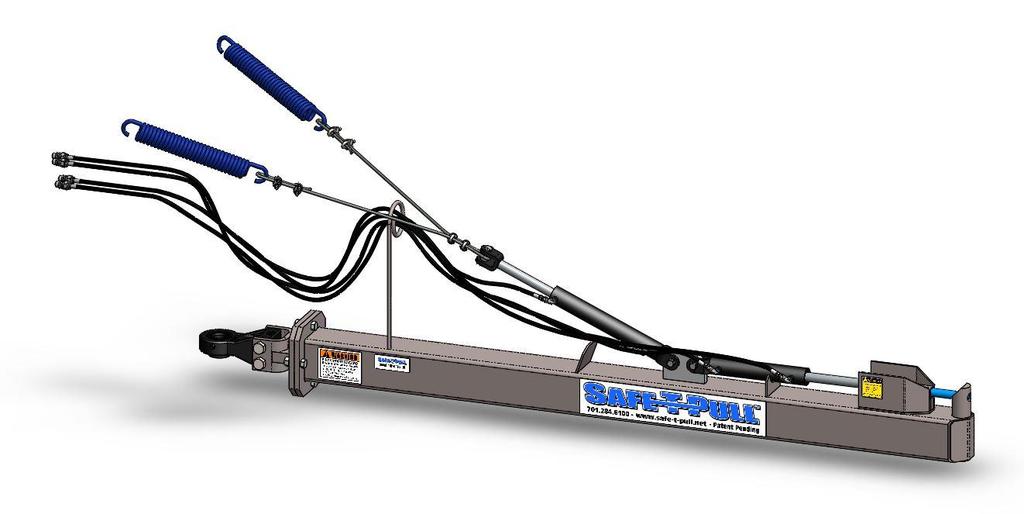
3 1. Before You Begin Disclaimer The information and specifications contained in this document are subject to change without notice. Safe- T-Pull Inc. assumes no responsibility or liability for any errors or omissions that may appear in this manual. Safe-T-Pull Inc. reserves the right to update the existing document or to create a new document to correct any errors or omissions. You can receive the latest version of this document from Safe-T-Pull Inc. by calling your nearest dealer during their business hours. What Is Included Safe-T-Pull ORIGINAL Puller Tube Safe-T-Pull ORIGINAL Bull Pull Tongue Two (2) Centering springs Claims If the packaging or the material inside the packaging (the product and included accessories) appear damaged from shipping, or show signs of mishandling, upon receipt notify the carrier immediately, not Safe-T-Pull Inc. Failure to do so in a timely manner may invalidate your claim with the carrier. In addition, keep the container and all the packing material for inspection. For other issues such as missing components or parts, damage not related to shipping, or concealed damage, file a claim with Safe-T-Pull Inc. immediately after receiving the merchandise. Self-contained hydraulics No Vertical Lift No Max pulling load* 160,000lbs Shock absorbing mechanism Yes Self-centering mechanism Springs and Cables *numbers based off grade 5 hardware Page 3 of 15
4 Contact Us Mail - Safe-T-Pull P.O. Box 94 Park River, ND Safety Information Please read the following Safety Notes carefully before working with the product. The Notes include important safety information about installation, usage, and maintenance. All personnel working on, with, or near a Safe-T-Pull ORIGINAL must wear safety toed shoes, safety glasses, reflective safety vest, protective gloves, and hard hat. The Safe-T-Pull ORIGINAL may raise or lower unexpectedly. When servicing the Safe-T-Pull ORIGINAL be sure the pulling vehicle is OFF and the puller arm is in the lowered position. Rules for safe hydraulic operation Park hydraulic machinery where children cannot reach it. If your pulling vehicle has hydraulic flow control capabilities, (usually measured in GPM) decrease the flow to 2 GPM. This is the minimum amount to operate a Safe-T-Pull ORIGINAL Block the Safe-T-Pull ORIGINAL when you must work on the system while raised; do not rely solely on the hydraulic lift. Avoid servicing the hydraulic system while the machine engine is running. Do not remove cylinders until the Safe-T-Pull ORIGINAL is resting on the ground or securely on safety stands or blocks; shut off engine. Before disconnecting hydraulic hoses, relieve all hydraulic pressure. Be sure all hose connections are tight and hoses are not damaged. Use a non-volatile cleaning solvent to wash parts. Three common hydraulic system hazards 1. Burns from very hot, high pressure fluid. 2. Injuries and illness from flailing hydraulic lines. 3. Hydraulic fluid injection into the body. Ways to prevent hazards from occurring When attempting to detect pinhole leaks in hydraulic hoses run a piece of cardboard or wood along the hose. NEVER touch hydraulic hoses when they are under pressure. Never connect a low pressure hose, cylinder, or other aftermarket equipment to the Safe-T-Pull ORIGINAL. Ensure all hydraulic components are in proper working condition on the pulling vehicle. Periodically check for oil leaks and worn hoses. Keep contaminants from hydraulic oil and replace filters regularly. Lubricate cylinder rods with protective lubricant to avoid rusting. Page 4 of 15

5 2. Introduction Product Dimensions Length 9 4 Width 10 Height 2 5 Weight 393lbs 3. Setup Assembly If your Safe-T-Pull ORIGINAL has been palletized, assembly is required. After unpacking follow these steps to assembly your Safe-T-Pull ORIGINAL. Unpacking Instructions Before discarding any packaging, be sure all included parts are accounted for. Remove all strapping and/or banding on the package Assembly Steps: Slide the tongue assembly into the puller tube assembly and fasten it with four (4) ¾ bolts, lock washers and nuts. Note: be sure the item isn t upside down. See the diagrams below. Installation BE SURE THE RING ON THE BULL PULL IS DOWN Recommended Tools: Lifting device (fork lift, skid-steer, cherry picker) WARNING: All equipment must be rated for 1,000 pounds (453.5kg) or more! Page 5 of 15


6 Installation Instructions Use a lifting device to align the Bull Pull of the Safe-T-Pull ORIGINAL between your tractor s drawbar and hammer strap. Slide your tractor s pin into the drawbar and lay the opposite end of the puller straight out from the tractor and let it rest upon the ground. Push your four (4) hydraulic hoses into your tractor s ports. o CAUTION: Ensure that all hydraulic equipment is in proper working order. Visit the Safety Information section in this document for more information. Use your tractor s hydraulics to extend the both cylinders fully. KEEP OTHERS AWAY! Extend Fully Page 6 of 15


7 Attach the two blue centering springs to a sturdy location on your tractor. It is best to install them 3 up and 3 apart from the Safe-T-Pull ORIGINAL tongue. See diagram below o NOTE: The top two mounts on a three point hitch work well Page 7 of 15
 Unpin the free end of the lift cylinder and insert the steel cable loop into it. Replace the pin into the lift cylinder.")

8 Attach the two ends of the included steel cable through the centering springs using the included cable clamps. Be sure the cable is tight and even on both sides to ensure proper alignment. (Be sure to install the saddle side onto the live end of the cable) Unpin the free end of the lift cylinder and insert the steel cable loop into it. Replace the pin into the lift cylinder. With all personnel clear, run the hydraulics to be sure the puller is straight off the back of the tractor when raised. If you need to make any adjustments, lower the puller all the way to the ground to relieve all spring pressure before you loosen any clamps. WARNING: Failure to do so can cause serious injury or even death! Raise the puller arm and check to make sure the height of the hook pin is high enough for your application. WARNING: Keep clear of pinch points when operating. Injury or death may occur. Page 8 of 15


9 4. Operation Instructions Pre-Operation Maintenance Before every operation of your Safe-T-Pull ORIGINAL an inspection and pre-operation maintenance should be done to ensure all components are in operating order: 1. Check hydraulic fluid in the pulling vehicle to make sure levels are adequate. 2. Check hydraulic hoses for cuts, cracks, pressure bubbles, or other damage. NOTE: Steel braiding should NEVER be visible 3. Check hydraulic fittings for dents, cuts, leaks, or other signs of damage. 4. Check to make sure all hydraulic hoses are securely fastened to their correct fittings. 5. Check to make sure all hydraulic cylinders pins are secured with correctly installed hitch clips and/or bolts. 6. Grease the Bull Pull hitch. NOTE: If your Safe-T-Pull ORIGINAL is being used continuously, pre-operation maintenance should be done before EVERY shift change. Operation Instructions Hooking up: Be sure ALL persons are clear of the operating area. With the Safe-T-Pull ORIGINAL arm in the lowered position, back the pulling vehicle up to the stuck vehicle. (A decrease in engine RPMs may be necessary for more precise control) Once the Safe-T-Pull OIGINAL s hook pin is directly under the Safe-T-Pull Truck Hitch pulling loop, raise the Safe-T-Pull ORIGINAL up (retract the lift cylinder) and into the Truck Hitch pulling loop. o WARNING: For your safety NEVER use the Safe-T-Pull ORIGINAL for pulling on unauthorized products. Close the Pin (extend the Pin Cylinder) to lock in the Truck Hitch. Lower the Safe-T-Pull ORIGINAL so that the springs are not under tension. o WARNING: Leaving the puller arm raised while pulling may damage your centering springs. Remove the downed vehicle from its location to a suitable location. To hook up, back the Safe-T-Pull Pro under the Truck Hitch. Lift the puller arm into the hitch loop and close the latch pin. Page 9 of 15

10 Unhooking: Open the lock pin (retract the Pin Cylinder) Lower the Safe-T-Pull ORIGINAL (extend the lift cylinder). If there is tension between the hook pin of the puller and pulling loop of the Truck Hitch, the puller may not lower. In this case a decrease in ground speed by the pulling vehicle may be required to free the pulling arm from the Truck Hitch. Once the Safe-T-Pull ORIGINAL is clear of the Truck Hitch, raise the pulling arm up (retract the lift cylinder) to keep it from dragging on the ground. NOTE: Your warranty will be void if you use a Safe-T-Pull Original with unauthorized products. 5. Technical Information Product Maintenance For proper operation ensure the following equipment is in proper operating condition. Hydraulic system Check hydraulic fluid in the pulling vehicle to make sure levels are adequate. Check hydraulic hoses for cuts, cracks, pressure bubbles, or other damage. NOTE: Steel braiding should NEVER be visible Check hydraulic fittings for dents, cuts, leaks, or other signs of damage. Check to make sure all hydraulic hoses are securely fastened to their correct fittings. Check to make sure all hydraulic cylinders pins are secured with correctly installed hitch clips and/or bolts. Steel Cable Check to make sure the steel cable is in good condition with no cuts, nicks, frays, or other damage. Check to make sure all cable clamps are securely tightened and installed correctly. Page 10 of 15
11 Centering springs Check to make sure both centering springs are securely fastened Check to make sure both centering springs are in good physical condition with no cuts, scratches, or scrapes. Check to make sure the spring is fully retracted without any tension on them. When the puller arm is resting on the ground no gap should be visible. If any gap is visible your spring has exceeded its maximum weight limit and should be replaced immediately. Grease Grease the Bull Pull hitch. 6. Technical Specifications Specifications Dimensions Length: 9 4 Width: 10 Height: 2 5 Weight 383lbs Hydraulic Power Source Pull vehicle System Voltage N/A Max psi 3000 psi Page 11 of 15

12 Replacement Parts Contact your authorized dealer or manufacturer representative to order replacement parts. Page 12 of 15


13 Warning! All stickers should be replaced if worn or unreadable! Page 13 of 15
14 7. Troubleshooting and FAQs 1) Does the Safe-T-Pull ORIGINAL come with everything I need to use it? Yes, all Safe-T-Pull products come ready for use. On the hydraulic hoses, we install ½ pioneer fittings for quick coupling. All the required fasteners, hardware, and hydraulic lines are included. NOTE: Hydraulic lines will be empty when you receive your Safe-T-Pull ORIGINAL. Fill lines before use. 2) What tools will I need to install the Safe-T-Pull ORIGINAL? Recommended tools Lifting device (fork lift, skid-steer, cherry picker) Rubber mallet/sand hammer 9/16 wrench WARNING: All lifting equipment must be rated for 1,000 pounds (453.5kg) or more! 3) How do I hook up the Safe-T-Pull ORIGINAL to the tractor? Use a lifting device to align the tongue of the Safe-T-Pull ORIGINAL into your tractor s drawbar Slide your tractor s pin into the drawbar (a rubber mallet/sand hammer may be needed) Push your four (4) hydraulic hoses into your tractor s ports. o CAUTION: Ensure that all hydraulic equipment is in proper working order. Visit the Safety Information section in this document for more information. Use your tractor s hydraulics to extend the lift cylinder Attach the two included centering springs to a sturdy location on your tractor. o NOTE: The top two mounts on a three point hitch work well Attach the two ends of the included steel cable to the centering springs using the included cable clamps. Unpin the free end of the lift cylinder and insert the steel cable into it. Replace the pin into the lift cylinder. With the puller arm still lowered adjust the slack in the steel cable until it becomes taught. Be sure to keep hoses and personnel away from all pinch points during operation. Follow all guidelines covered in the Safety Information section of this document. 4) My draw bar is only 3 wide with a 1 ½ pin; will the Safe-T-Pull ORIGINAL work? Yes, you will have to use a bushing on your pin to avoid unnecessary wear. Page 14 of 15
15 5) My draw bar is 5 wide with 2 3/4 pin; will the Safe-T-Pull ORIGINAL work? Yes, you will have to use a 2 pin and use bushings on your drawbar. 6) How long should I expect my Safe-T-Pull ORIGINAL to last? Forever! The first Safe-T-Pulls are over 20 years old and are still in use. Depending on how well your Safe-T- Pull ORIGINAL is cared for and how often it is used, very few parts will need to be replaced. Some replacement parts will wear out faster than others. 7) Is there something to cushion the pull? The Safe-T-Pull has a shock absorbing compression spring built into the internals of the pulling arm. This technology allows the puller to flex and absorb the jerk upon take off, acting like a nylon rope without the dangers and limitations. 8) Can I order replacement parts if something were to wear out? Yes. Please contact your local dealer or manufacturer representative for ordering your replacement parts. Most of our parts are made in-house and are in stock. 9) How soon can I expect my Safe-T-Pull ORIGINAL? Once the order has been placed with your dealer or manufacturer representative, we will do our best to get your product to you as quickly as possible. Most of our orders will ship same-day. However, during our busy season (September thru November) production may be backed up by over two weeks. To avoid any delays it is best to place orders early. NOTE: Freight shipments to some parts of the country may take up to a week or more. 10) How soon can I expect my Safe-T-Pull replacement parts? Once the order has been placed with your dealer or manufacturer representative, we will do our best to get your product to you as quickly as possible. All of our replacement parts are in stock and will usually be shipped same-day. There is a risk of parts being out of stock during our busy season (September thru November). To avoid any delays it is best to place orders early. NOTE: Freight shipments to some parts of the country may take up to a week or more. Page 15 of 15
Pro. User Manual. Safe-T-Pull Inc Page 1 of 19
 Pro User Manual Safe-T-Pull Inc. 2015 Page 1 of 19 TABLE OF CONTINENTS 1. Before You Begin...3 Disclaimer...3 What Is Included...3 Unpacking Instructions....4 Claims...4 Contact Us...4 Safety Information...4
Pro. User Assembly & Install Guide. Safe-T-Pull Inc. Page 1 of 9
 Pro User Assembly & Install Guide Safe-T-Pull Inc. Page 1 of 9 Safety Information Please read the following safety notes carefully before working with the Safe-T-Pull PRO. These notes include important
TABLE OF CONTENTS. 1. Before You Begin 3 Disclaimer 3 What Is Included 3 Optional Accessories 3 Unpacking Instructions 3 Claims 3 Contact Us 3
 Page 1 of 25 TABLE OF CONTENTS 1. Before You Begin 3 Disclaimer 3 What Is Included 3 Optional Accessories 3 Unpacking Instructions 3 Claims 3 Contact Us 3 2. Safety Information 4 Safety Notes 4 Rules for
US208S Scooter Carrier - US208P Power Chair Carrier 210 Lift N Go 130 Swing Away Installation Guide & Owners Manual
 7325 Douglas Rd. Lambertville, MI 48144 Phone: 1-800-541-3213 Fax: (734) 568-6705 www.wheelchaircarrier.com E-mail: admin@wheelchaircarrier.com US208S Scooter Carrier - US208P Power Chair Carrier 210 Lift
Model 289F. Operator s Manual for Morse Model 289F. MORStak TM Forklift-Mounted Drum Racker. The Specialist In Drum Handling Equipment
 Contents Page Receiving Procedures.................... 1 Warranty............................. 1 Safety Information..................... 1-2 Machine Description................... 3 Operating Instructions....................
Lift N Go [Model 210] Electric Carrier For use with power chairs & scooters Installation Guide & Owners Manual
![Lift N Go [Model 210] Electric Carrier For use with power chairs & scooters Installation Guide & Owners Manual](/thumbs/74/70316262.jpg "Lift N Go [Model 210] Electric Carrier For use with power chairs & scooters Installation Guide & Owners Manual") 203 Matzinger Road Toledo, OH 43612 Phone: 1-800-541-3213 Fax: (419) 478-4425 www.wheelchaircarrier.com E-mail: admin@wheelchaircarrier.com Lift N Go [Model 210] Electric Carrier For use with power chairs
203 Matzinger Road Toledo, OH 43612 Phone: 1-800-541-3213 Fax: (419) 478-4425 www.wheelchaircarrier.com E-mail: admin@wheelchaircarrier.com Lift N Go [Model 210] Electric Carrier For use with power chairs
3-Pt. Quick Hitch. Owner s Manual
 3-Pt. Quick Hitch Owner s Manual WARNING: Read carefully and understand all ASSEMBLY AND OPERATION INSTRUCTIONS before operating. Failure to follow the safety rules and other basic safety precautions may
Extreme Duty Grapple (Rock, Skeleton, Scrap & Tine) Operation and Maintenance Manual
 Operation and Maintenance Manual") Extreme Duty Grapple (Rock, Skeleton, Scrap & Tine) Operation and Maintenance Manual Revision Date: May 12, 2017 Skid Pro PO Box 982 Alexandria, MN 56308 Toll Free: 877-378-4642 www.skidpro.com TABLE OF
Extreme Duty Grapple (Rock, Skeleton, Scrap & Tine) Operation and Maintenance Manual Revision Date: May 12, 2017 Skid Pro PO Box 982 Alexandria, MN 56308 Toll Free: 877-378-4642 www.skidpro.com TABLE OF
Extreme Duty Grapple (Rock, Skeleton, Scrap & Tine) Operation and Maintenance Manual
 Operation and Maintenance Manual") Extreme Duty Grapple (Rock, Skeleton, Scrap & Tine) Operation and Maintenance Manual Revision Date: July 2017 Skid Pro PO Box 982 Alexandria, MN 56308 Toll Free: 877-378-4642 www.skidpro.com TABLE OF CONTENTS
Extreme Duty Grapple (Rock, Skeleton, Scrap & Tine) Operation and Maintenance Manual Revision Date: July 2017 Skid Pro PO Box 982 Alexandria, MN 56308 Toll Free: 877-378-4642 www.skidpro.com TABLE OF CONTENTS
Model 3400 ATTENTION: WARNING
 B&W Trailer Hitches 1216 Hawaii Road / PO Box 186 Humboldt, KS 66748 P:620.473.3664 F:620.473.3766 NOTE: We recommend reading instructions before beginning the installation. Companion Slider Hitch Installation
Operating Instructions & Parts Manual. Fuel Tank Adapter
 Operating Instructions & Parts Manual Fuel Tank Adapter Model Number 40080 Capacity 80 lb.! This is the safety alert symbol. It is used to alert you to potential personal injury hazards. Obey all safety
Owner s Instructions and Safety Manual. Switcharoo series. Performance Bicycle Trailers
 Owner s Instructions and Safety Manual Switcharoo series TM Performance Bicycle Trailers Contents 1. Trailer Components 2. Tow Bar and Hitch Components 3. Assembling Your Trailer 4. Attaching the Wheels
US208S Scooter / Power Chair Carrier Lift N Go 117 Mini Electric Lift Electric Tote & 130 Swing Away Installation Guide & Owners Manual
 7325 Douglas Rd. Lambertville, MI 48144 Phone: 1-800-541-3213 Fax: (734) 568-6705 www.wheelchaircarrier.com E-mail: admin@wheelchaircarrier.com US208S Scooter / Power Chair Carrier - 210 Lift N Go 117
RAPID ROLLER OPERATOR S MANUAL. L&C ENTERPRISES - U.S.A, Inc N.75 Drive, Escanaba, MI OWNER S NAME MODEL
 RAPID ROLLER OPERATOR S MANUAL OWNER S NAME MODEL SERIAL NUMBER DATE OF PURCHASE L&C ENTERPRISES - U.S.A, Inc. 6652 N.75 Drive, Escanaba, MI 49829 906-786-1008 1-866-786-1009 LIMITED WARRANTY L&C Enterprises-USA,
B&W Trailer Hitches 1216 Hawaii Road / PO Box 186 Humboldt, KS P: F: " Split Lock Washers 8
 B&W Trailer Hitches 1216 Hawaii Road / PO Box 186 Humboldt, KS 66748 P:620.473.3664 F:620.869.9031 NOTE: We recommend reading instructions before beginning the installation. Companion Slider Hitch Installation
<THESE INSTRUCTIONS MUST BE GIVEN TO THE END USER> 1 2 " X 1 1 2" Hex Cap Screws " Split Lock Washers " Threaded block 4
 B&W Trailer Hitches 1216 Hawaii Rd / PO Box 186 Humboldt, KS 66748 P:620.473.3664 F:620.473.3766 Companion Hitch Installation Instructions 20,000 LBS.
2-300 SERIES Endover Rotator Operator s Manual for Morse End-Over-End Drum Rotators Series
 Contents Page Receiving Procedures.................... 1 Warranty............................. 1 Safety Information..................... 1-2 Machine Description................... 2 Operating Instructions....................
OPERATIONS MANUAL LEVER CHAIN HOIST
 OPERATIONS MANUAL LEVER CHAIN HOIST IMPORTANT SAFETY INFORMATION Please read, understand and follow all safety information contained in these instructions prior to the use of this hoist. Retain these instructions
VEGETABLE OIL DISPOSAL UNIT (MSDU) OPERATOR & SERVICE MANUAL
 OPERATOR & SERVICE MANUAL") VEGETABLE OIL DISPOSAL UNIT (MSDU) OPERATOR & SERVICE MANUAL MANUFACTURED BY P.O. BOX 51000 SHREVEPORT, LOUISIANA 71135-1000 PHONE 1-318-865-1711 1-800-24 FRYER This equipment chapter is to be inserted
VEGETABLE OIL DISPOSAL UNIT (MSDU) OPERATOR & SERVICE MANUAL MANUFACTURED BY P.O. BOX 51000 SHREVEPORT, LOUISIANA 71135-1000 PHONE 1-318-865-1711 1-800-24 FRYER This equipment chapter is to be inserted
SPECIFICATIONS GENERAL SAFETY RULES PERSONAL SAFETY. Save This Manual TOOL USE AND CARE WORK AREA
 SPECIFICATIONS 2 Forged Safety Latch Hooks Cable extends to: 44 Drop forged steel hanging bracket Heavy duty 3/16 Steel Cable Pulling Capacity: 1200 LB. One piece double ratchet gear Save This Manual You
ELECTRIC HOIST MODEL NO: CH2500B, CH4000B OPERATION & MAINTENANCE INSTRUCTIONS PART NO: , LS1010
 ELECTRIC HOIST MODEL NO: CH2500B, CH4000B PART NO: 7630386, 7630391 OPERATION & MAINTENANCE INSTRUCTIONS LS1010 INTRODUCTION Thank you for purchasing this CLARKE Electric Hoist. Before attempting to use
305 Series Can Tumblers Operator s Manual for Morse Can Tumblers 305 Series
 Contents Page Receiving Procedures.................... 1 Warranty............................. 1 Safety Information..................... 1-2 Machine Description................... 3 Operating Instructions....................
<THESE INSTRUCTIONS MUST BE GIVEN TO THE END USER> B&W
 B&W Trailer Hitches 26 Hawaii Road / PO Box 86 Humboldt, KS 6678 P:620.73.366 F:620.869.903 GM Puck Mount System Installation Instructions 20,000 LBS.
(SDU 50, SDU 90, and BKSDU) Shortening Disposal Unit * * Installation, Operation, Service, and Parts Manual
 Shortening Disposal Unit * * Installation, Operation, Service, and Parts Manual") Shortening Disposal Unit (SDU 50, SDU 90, and BKSDU) Installation, Operation, Service, and Parts Manual Frymaster, a member of the Commercial Food Equipment Service Association, recommends using CFESA
Shortening Disposal Unit (SDU 50, SDU 90, and BKSDU) Installation, Operation, Service, and Parts Manual Frymaster, a member of the Commercial Food Equipment Service Association, recommends using CFESA
456 Series Hydra-Lift Drum Rollers Operator s Manual for Morse Hydra-Lift Drum Rollers 456 Series
 Contents Page Receiving Procedures.................... 1 Warranty............................. 1 Safety Information..................... 1-2 Machine Description................... 3 Options.........................
B&W Trailer Hitches 1216 Hawaii Road / PO Box 186 Humboldt, KS P: F:
 B&W Trailer Hitches 1216 Hawaii Road / PO Box 186 Humboldt, KS 66748 P:620.473.3664 F:620.473.3766 NOTE: We recommend reading instructions before beginning the installation. GM OEM Mount System Slider
<THESE INSTRUCTIONS MUST BE GIVEN TO THE END USER> BASE BOLT BAG (RVB3500) ITEM DESCRIPTION QTY. 1 2 " X 1 1 2" Hex Cap Screws 16
 ITEM DESCRIPTION QTY. 1 2 X 1 1 2 Hex Cap Screws 16") B&W Trailer Hitches 1216 Hawaii Rd / PO Box 186 Humboldt, KS 66748 P:620.473.3664 F:620.869.9031 Companion Hitch Installation Instructions 20,000 LBS.
B&W Trailer Hitches 1216 Hawaii Rd / PO Box 186 Humboldt, KS 66748 P:620.473.3664 F:620.869.9031 Companion Hitch Installation Instructions 20,000 LBS.
<THESE INSTRUCTIONS MUST BE GIVEN TO THE END USER> B&W Trailer Hitches 1216 Hawaii Road / PO Box 186 Humboldt, KS P: F:
 B&W Trailer Hitches 26 Hawaii Road / PO Box 86 Humboldt, KS 6678 P:620.73.366 F:620.869.903 Ford OEM Mount System Installation Instructions 20,000 LBS.
AG PRO SS Owner s Manual & Parts Book
 AG PRO SS Owner s Manual & Parts Book Purchase Date Serial Number Model Number Tractor Model Dealer PN: 63-19460 SN: 10204276-... Date 1-10-2017 Description Contents Page To The Owner, Maintenance, Safety
Installation and Operation Manual
 1645 Lemonwood Dr. Santa Paula, CA 93060 USA Toll Free: 1 (800) 253-2363 Tel: 1 (805) 933-9970 rangerproducts.com Ranger Floor Jack Installation and Operation Manual Manual Revision B July 2017 Manual
Safety, Operation and Maintenance Instructions For Long & Short Nose Upholstery Air Stapler (NS10 & NS11)
") Safety, Operation and Maintenance Instructions For Long & Short Nose Upholstery Air Stapler (NS10 & NS11) Important: Drop 3 drops of oil into the stapler air inlet BEFORE first use. See page 2. Please
Safety, Operation and Maintenance Instructions For Long & Short Nose Upholstery Air Stapler (NS10 & NS11) Important: Drop 3 drops of oil into the stapler air inlet BEFORE first use. See page 2. Please
ALUMINUM CARGO CARRIER WITH FOLDING RAMP
 ALUMINUM CARGO CARRIER WITH FOLDING RAMP OWNER S MANUAL WARNING: Read carefully and understand all ASSEMBLY AND OPERATION INSTRUCTIONS before operating. Failure to follow the safety rules and other basic
<THESE INSTRUCTIONS MUST BE GIVEN TO THE END USER> B&W Trailer Hitches 1216 Hawaii Road / PO Box 186 Humboldt, KS P: F:
 B&W Trailer Hitches 26 Hawaii Road / PO Box 86 Humboldt, KS 66748 P:620.473.3664 F:620.869.903 Ford OEM Mount System Installation Instructions 20,000
SERIES 04 DIAMOND HARROW PRODUCT MANUAL FOR SECTIONS & SETS
 SERIES 04 DIAMOND HARROW PRODUCT MANUAL FOR SECTIONS & SETS TABLE OF CONTENTS Welcome Note 4 Safety 5 Usage Information 7 Normal Packaging 9 Assembly Instructions 10 Operating Instructions 13 Series 04
ELECTRIC HOIST MODEL NO: CH2500B, CH4000B OPERATION & MAINTENANCE INSTRUCTIONS PART NO: ,
 ELECTRIC HOIST MODEL NO: CH2500B, CH4000B PART NO: 7630386, 7630391 OPERATION & MAINTENANCE INSTRUCTIONS ORIGINAL INSTRUCTIONS LS0517 - Iss 5 INTRODUCTION Thank you for selecting this Clarke Electric Hoist.
B&W Trailer Hitches 1216 Hawaii Road / PO Box 186 Humboldt, KS P: F:
 B&W Trailer Hitches 1216 Hawaii Road / PO Box 186 Humboldt, KS 66748 P:620.473.3664 F:620.869.9031 NOTE: We recommend reading instructions before beginning the installation. Ford OEM Mount System Slider
THE GIANT-VAC PTO BLOWER MODELS 2000*/3200**/4000***
 THE GIANT-VAC PTO BLOWER MODELS 2000*/3200**/4000*** Congratulations! ASSEMBLY INSTRUCTIONS AND OPERATOR S MANUAL You have just purchased one of the finest pieces of outdoor power equipment on the market
270PK SERVICE GUIDELINES
 270 Coupling THE FIRST NAME IN QUALITY COUPLINGS 270PK SERVICE GUIDELINES BEFORE GETTING STARTED: This procedure should only be performed by a qualified mechanic. Measure the wear on the coupling s pintle
Butterfly Valve Type 57P
 Butterfly Valve Type 57P Contents Lever Type: 50-200 mm (2-8 ) Body Material: CPVC Gear Type: 50-200mm (2-8 ) Body Material: CPVC (1) Be sure to read the following warranty clauses of our product 1 (2)
Maintenance and Repair
 Maintenance and Repair WARNING ALWAYS shut off the engine, remove key from ignition, make sure the engine is cool, and disconnect the spark plug and positive battery terminal from the battery before cleaning,
Operation and Safety Manual
 Barrel Handler Operation and Safety Manual EZ SPOT UR Inc. 803 25 th St. N Fargo, ND 58102 Toll Free: 877 433 5733 Phone: 701 282 2772 Fax: 701 277 4625 Table of Contents Safety Symbols & Equipment Signs...
Shortening Disposal Unit
 Shortening Disposal Unit (SDU 50, 90, 100 and BKSDU) Installation, Operation, Service and Parts Manual Frymaster, a member of the Commercial Food Equipment Service Association, recommends using CFESA Certified
<THESE INSTRUCTIONS MUST BE GIVEN TO THE END USER> B&W Trailer Hitches 1216 Hawaii Road / PO Box 186 Humboldt, KS P: F:
 B&W Trailer Hitches 26 Hawaii Road / PO Box 86 Humboldt, KS 6678 P:620.73.366 F:620.869.903 RAM OEM Mount System Installation Instructions 25,000 LBS.
OPERATOR'S MANUAL & PARTS LIST
 GRAVITY GRAIN BOES OPERATOR'S MANUAL & PARTS LIST GRAVITY GRAIN BOES Model 50 (After Serial #14860 & D-Series) Model 85 (After Serial #C104749 & D-Series) Model 90 (After Serial #D0580100 & Up) Model 450
Butterfly Valve Type 58 (PDCPD)
") Serial No. H-V074-E Butterfly Valve Type 58 (PDCPD) 700mm (28 ) User s Manual Contents (1) Be sure to read the following warranty clauses of our product 1 (2) General operating instructions 2 (3) General
Serial No. H-V074-E Butterfly Valve Type 58 (PDCPD) 700mm (28 ) User s Manual Contents (1) Be sure to read the following warranty clauses of our product 1 (2) General operating instructions 2 (3) General
48 in. DELUXE ALUMINUM CARGO CARRIER WITH RAMP
 48 in. DELUXE ALUMINUM CARGO CARRIER WITH RAMP OWNER S MANUAL WARNING: Read carefully and understand all ASSEMBLY AND OPERATION INSTRUCTIONS before operating. Failure to follow the safety rules and other
Model 3770 WARNING. Failure to comply with the safety information in these instructions could result in serious injury or death.
 B&W Trailer Hitches 1216 Hawaii Road / PO Box 186 Humboldt, KS 66748 P:620.473.3664 See Limited Lifetime Warranty at F:620.869.9031 bwtrailerhitches.com/warranty NOTE: We recommend reading instructions
Operator s Manual. Go Galvanized! YOU'RE ALWAYS AHEAD...WITH A MODERN BEHIND.
 SUMMER 2008 C2 tilting grader blade Operator s Manual YOU'RE ALWAYS AHEAD...WITH A MODERN BEHIND. 003-5336 003-5342 003-5531 003-5544 P.O. Box 790 Beaumont, Tx 77704 409.833.2665 1.800.231.8198 Fax: 409.726.8333
Sediment strainer (Type Y)
") Installation,Operation and Maintenance Manual Serial No. H-V034-E-9 Sediment strainer (Type Y) Contents (1) Be sure to read the following warranty clauses of our product 1 User s Manual (2) General operating
Installation,Operation and Maintenance Manual Serial No. H-V034-E-9 Sediment strainer (Type Y) Contents (1) Be sure to read the following warranty clauses of our product 1 User s Manual (2) General operating
TABLE OF CONTENTS Safe Use Checklist Registration & Recal Assistance Warnings Base Features Carrier Features Securing Child In Carrier
 TABLE OF CONTENTS Safe Use Checklist...4 Registration & Recall...5 Assistance...5 Warnings...6 Base Features Base Overview... Storage Compartment...3 Recline Adjustment...3 LATCH Removal & Storage...4
BUCKET SWEEPER OPERATORS & PARTS MANUAL 2852 & 3174 SERIES
 OM628 BUCKET SWEEPER OPERATORS & PARTS MANUAL 2852 & 3174 SERIES MODEL 12002-5 FOOT WIDE X 24 INCH DIAMETER (SKID-STEER) MODEL 12004-6 FOOT WIDE X 24 INCH DIAMETER (SKID-STEER) MODEL 12017-6 FOOT WIDE
W & A 12 ROW TOP LEVELING STACKER LEVEL BANDER
 W & A 12 ROW TOP LEVELING STACKER LEVEL BANDER NO. 3640 OPERATOR S MANUAL TO THE OWNER: Congratulations on your purchase of a new W & A Top Leveling Stacker Level Bander. Your selection is an indication
MODEL LR-2066 & LR-2866A HOIST INSTALLATION AND OPERATION MANUAL
 TRUCK BODIES & EQUIPMENT INTERNATIONAL, Inc. Website: www.rugbymfg.com E-mail: sales@rugbymfg.com Phone: 1-800-869-9162 03 5839 MODEL LR-2066 & LR-2866A HOIST INSTALLATION AND OPERATION MANUAL Hoist Serial
General Guidelines. Instructions for Part # SC-SWING-AWAY-V2. Safety
 Instructions for Part # SC-SWING-AWAY-V2 General Guidelines It is the user s responsibility to read and follow all instructions. Keep these instructions with the product at all times and review before
On-A-Roll Lifter Instruction Manual for Standard Models Read Before Use!
 On-A-Roll Lifter Instruction Manual for Standard Models Read Before Use! Important instructional, safety and precautionary information! It is the user s responsibility to exercise good judgment, common
! CAUTION! ! WARNING!
 Assembly Instructions! 24- and 30-Foot, No-Till Flat Fold Marker Option Used with: 2N-2410 and 2N-3010 Drills 2N-2420 and 2N-3020 Drills When you see this symbol, the subsequent instructions and warnings
OPERATOR S MANUAL. 20-bu 3-Point Hitch Material Collection System. LP65048 Supplier ST /07/2017 English. North American Edition Printed in USA
 OPERATOR S MANUAL 20-bu 3-Point Hitch Material Collection System LP65048 Supplier ST48289 11/07/2017 English North American Edition Printed in USA Introduction Using Your Operator s Manual Read this entire
MG12K24T60V4 Mechanical Grapple
 170 State Route 271 Attachment Solutions MG12K24T60V4 Mechanical Grapple Operators Manual KENCO Mechanical Grapple Operation Manual 1 TABLE OF CONTENTS 170 State Route 271 Section I. General Information....
RAMPAGE POWER LIFT RAMP
 RAMPAGE POWER LIFT RAMP INSTALLATION AND OPERATING INSTRUCTIONS (3/10/07) The Rampage Power Lift Ramp is the fast, easy, and safe way to load a motorcycle into a truck. One person can load or unload a
HIGH RISE POWER ANGLE KIT
 HIGH RISE POWER ANGLE KIT P/N 33-0100 OWNER S MANUAL Application HIGH RISE PUSH TUBE 33-0000 & 34-0000 ATTENTION DEALER: CUSTOMER MUST RECEIVE A COPY OF THIS MANUAL AT THE TIME OF SALE. Before you begin,
16K Reese Revolution. Operating Instructions
 Operating Instructions DEALER: (1) Provide this Manual to end user END USER: (1) Read and follow this Manual every time you use Sidewinder. (2) Save this Manual for Future Reference. PIN BOX SHOWN ASSEMBLED
Kit No Please read these instructions completely before proceeding with installation. Air Spring Kit Parts List. Bracket Attaching Hardware
 Kit No. 59532 MN-572 (021108) ECR 7136 Please read these instructions completely before proceeding with installation Air Spring Kit Parts List A Item Description Quantity A Air Sleeves 2 B Upper Brackets
REV 1 400DB HYDRAULIC HITCH OWNER S MANUAL
 400DB HYDRAULIC HITCH OWNER S MANUAL Page 2 Table of Contents Page 3 Specifications...4 Contacting the Company...4 Safety Instructions...5 Maintenance...6 Troubleshooting...7 Installation Instructions...8
16K Revolution Service Kit Instructions 86016
 86016 Equipment Required: Wrenches: 15/16, 1 1/8, Torque Wrench, Rubber Mallet Included Service Kit Items: 1 Qty. (1) Wear Plate 2 Qty. (1) Pivot Bushing 3 Qty. (1) Bearing Cup 4 Qty. (1) Bearing 1 5 Qty.
Table of Contents. Safety Assembly Pre-operation / Starting. 7. Operation.. 8. Maintenance. 9. Storage 10
 Table of Contents Safety... 3 Assembly... 6 Pre-operation / Starting. 7 Operation.. 8 Maintenance. 9 Storage 10 Parts drawings..11 Parts list by number..12 Notes.13 2 Safety Information Attention; this
HEAVY DUTY TROLLEY JACK. Operation Manual
 HEAVY DUTY TROLLEY JACK 4T Operation Manual Make sure to read and fully understand the instruction manual before using this product and keep the manual properly 1 General Description Product Description
MS2200, MS2500, and MS3000 Suspension Installation Manual ON/OFF HIGHWAY SUSPENSION SYSTEM
 MS22, MS25, and MS3 Suspension Installation Manual ON/OFF HIGHWAY SUSPENSION SYSTEM 972.547.62 8.445.736 FAX: 972.542.97 725 E. UNIVERSITY ST. McKINNEY, TEXAS 7569 www.watsonsuspensions.com Watson & Chalin
Post Driver Attachment
 Attachment (Shown with Optional Power Cell Rotator) Models - 600, 850 Safety Instructions This safety alert symbol indicates important safety messages in this manual. When you see this symbol, carefully
Ball Hawk 3 Gang & 5 Gang Manual
 Ball Hawk 3 Gang & 5 Gang Manual Call 1-800-869-1800 or go online at www.wittekgolf.com to order! UNPACKING AND INSPECTION The Wittek Ball Hawk LT Pickers are packed complete with all component parts in
Operating and Assembly Manual
 Model 1080 Operating and Assembly Manual Midwest Equipment Manufacturing, Inc. 5225 Serum Plant Road Thorntown, IN 46071 08-02-16 SAFETY RULES Remember, any power equipment can cause injury if operated
08/2010 Rev. 4/28/2017 FMDL, MANUAL. FMDL-Series Single & Double Eagle Beak Fork-Mounted Drum Lifters Use and Maintenance Manual
 Vestil Manufacturing Corp. 2999 North Wayne Street, P.O. Box 507, Angola, IN 46703 Telephone: (260) 665-7586 -or- Toll Free (800) 348-0868 Fax: (260) 665-1339 www.vestilmfg.com Email: info@vestil.com FMDL-Series
Range Rover 3 Gang & 5 Gang Manual
 Range Rover 3 Gang & 5 Gang Manual Call 1-800-869-1800 or go online at www.wittekgolf.com to order! UNPACKING AND INSPECTION The Wittek Range Rover Pickers are packed complete with all component parts
MK AUGERS POWER SWING KIT ASSEMBLY & OPERATION MANUAL
 MK AUGERS POWER SWING KIT ASSEMBLY & OPERATION MANUAL Read this manual before using product. Failure to follow instructions and safety precautions can result in serious injury, death, or property damage.
RED23305 Owner s Manual
 RED23305 Owner s Manual 5 foot, 3-Point Mounted Snow Blower 270 West Park Avenue Huron, SD 57350 866-526-5682 Serial Number: Date of Purchase: Red Devil Snow Blower See Figure 1. 1. The Red Devil Snow
MANUFACTURING CO. THE FIRST NAME IN QUALITY COUPLINGS. Installation, Inspection, Operation & Maintenance Guide. Model 880 Coupling IMPORTANT
 MANUFACTURING CO. THE FIRST NAME IN QUALITY COUPLINGS Installation, Inspection, Operation & Maintenance Guide Model 880 Coupling IMPORTANT Read these instructions completely before installing, using or
SERIES OPERATION AND MAINTENANCE MANUAL
 SERIES OPERATION AND MAINTENANCE MANUAL This manual CONTAINS IMPORTANT WARNINGS, S and OTHER INSTRUCTIONS. Read and understand the instruction manual Carefully, before use and retain it for reference.
Installation Instructions
 Installation Instructions Rear Disc Brake Conversion Kit Item # RC4001, RC4001X Applications: Mopar 7.25, 8.25, 9.25 Axles Thank you for choosing Leed Brakes for your automotive product needs. Before you
Operator s Manual and Assembly
 Operator s Manual and Assembly Published: Mar 24, 2017 Manual Part No. AH02-00-MAN Gatco Manufacturing Inc. www.gatcomfg.com Location: 2524 South Service Road West, Swift Current, SK, Canada Mail: Box
Cylinder Installation Compression/Stripper, for Models, 22HF, 16HF, 1600 machines
 Knowledge Base Article Type: Instructions Cylinder Installation Compression/Stripper, for Models, 22HF, 16HF, 1600 machines Description: Instructions on How to properly install stripper beam and compression
PNEUMATIC SLIDING VALVE
 INSTALLATION, OPERATION, & #: MM-SV001 6-23-09 Rev. A Page 1 of 8 PNEUMATIC SLIDING VALVE PART NUMBERS (Including, but not inclusive) SV704MSTS, SV714MSTS, SV754MSTS, SV764MSTS, SV774MSTS, SV706MSTS, SV716MSTS,
ProLine. 44 Mower. for 120 Traction Unit. Model No & Up. Operator s Manual
 FORM NO. 9 ProLine Mower for 0 Traction Unit Model No. 05 99000 & Up Operator s Manual IMPORTANT: Read this manual carefully. It contains information about your safety and the safety of others. Also become
WARNING this attachments capacity changes depending on the Skid Steer Loader it is hooked up to. CAPACITY AT 24 LOAD CENTER
 SKID STEER FORKLIFT ATTACHMENT Any piece of equipment can be dangerous if not operated properly. YOU are responsible for the safe operation of this equipment. The operator must carefully read and follow
APCO ASR-400/450 SEWAGE AIR RELEASE VALVES
 APCO ASR-400/450 SEWAGE AIR RELEASE VALVES Instruction D12005 December 2012 Instructions These instructions provide installation, operation and maintenance information for the APCO ASR- 400/450 Sewage
OPERATOR S AND PARTS MANUAL PALLET FORKS. Part Number: MODEL NUMBER: Rev. 4
 OPERATOR S AND PARTS MANUAL PALLET FORKS SERIAL NUMBER: Manual Number: OM642 Part Number: 75542 MODEL NUMBER: Rev. 4 800-456-7100 I www.paladinlcg.com 503 Gay Street, Delhi, IA 52223, United States of
Owner s Instructions and Safety Manual. Double-Double series. Performance Bicycle Trailers
 Owner s Instructions and Safety Manual Double-Double series TM Performance Bicycle Trailers Contents 1. Trailer Components 2. Tow Bar and Hitch Components 3. Assembling Your Trailer 4. Attaching the Wheels
! CAUTION! ! WARNING!
 Assembly Instructions! 3N-3010P, No-Till Flat Fold Marker Option Used with: 3N-3010P Drills When you see this symbol, the subsequent instructions and warnings are serious - follow without exception. Your
Instructions Suzuki Samurai Brake System Bleeding. Suggested Tools:
 86-95 Suzuki Samurai Brake System Bleeding Instructions CAUTION: Safety glasses should be worn at all times when working with vehicles and related tools and equipment. Suggested Tools: Brake Fluid, DOT
Convertible - Rated 3 4-Ton /2-Ton Nylon Strap Hoists Refer to any questions about the use, application, repair or testing of this hoist to:
 Operating and Servicing Instructions for Convertible - Rated 3 4-Ton - 1 1 /2-Ton Nylon Strap Hoists Refer to any questions about the use, application, repair or testing of this hoist to: Hubbell / Chance
Bray/ VAAS Slurry Series Knife Gate Valve 760/762/765/766/767/768 Series Operation and Maintenance Manual
 Bray/ VAAS Knife Gate Valve 760/762/765/766/767/768 Series Table of Contents Definition of Terms 1 Safety Instructions 1 Introduction 2 Unpacking 2 Storage 2 Installation 3 Commissioning 3 Cylinder-Operated
Butterfly_Valve_Type57P
 Butterfly Valve Type 57P Contents Lever Type: 40-200 mm (1 1/2-8 ) Body Material: PVC, PP, PVDF Lever Type: 50-200 mm (2-8 ) Body Material: CPVC Gear Type: 40-350mm (1 1/2-14 ) Body Material: PVC, PP,
45 TRAILING PAVEMENT/LEAF/LAWN SWEEPER MODEL MH-4451
 45 TRAILING PAVEMENT/LEAF/LAWN SWEEPER MODEL MH-4451 Owner s Manual and Parts List SAVE THIS MANUAL You will need this manual for the safety instructions, assembly instructions and parts list. Put it in
610 BUSHEL MANURE SPREADER
 610 BUSHEL MANURE SPREADER RODA MANUFACTURING 1008 LOCUST ST. HULL, IA. 51239 Art s-way Manufacturing 712-439-2366 Co., Inc. Hwy 9 West - PO Box 288 WWW.RODAMFG.COM Armstrong, IA. 50514 U.S.A 2 INTRODUCTION
OPERATOR'S MANUAL 304 Row Mulcher
 OPERATOR'S MANUAL 0 Row Mulcher PUBLICATION DATE: // Millcreek Manufacturing Company Reservoir Road Honey Brook PA MILLCREEK PART# 0 WARNING: DO NOT assemble, operate, or maintain this equipment without
Part# Description Q'TY
 4 Bike Rack Carrier The 4 Bike Rack is to protect your bikes during transportation. This device is built for carrying up to 4 bikes at one time. This device also has a drop down feature so you can still
INSTALLATION, OPERATION AND MAINTENANCE MANUAL WALL EXHAUST FANS BELT DRIVE XBL FANS
 INSTALLATION, OPERATION AND MAINTENANCE MANUAL WALL EXHAUST FANS BELT DRIVE XBL FANS The purpose of this manual is to aid in the proper installation and operation of the fans. These instructions are intended
Owner s Manual: PSHV SERIES WINCHES
 Owner s Manual: PSHV SERIES WINCHES PIERCE ARROW INC. 549 U.S. HWY 287 S. HENRIETTA, TEXAS 76365 -------------------------------------------------------TOLL FREE 800-658-6301 FAX 940-538-4382 -------------------------------------------------------www.piercearrowinc.com
GROUNDSMASTER. 52 Recycler. for 120 Traction Unit. Model No & UP. Operator s Manual
 FORM NO. 8-980 Rev A GROUNDSMASTER 5 Recycler for 0 Traction Unit Model No. 077 79000 & UP Operator s Manual IMPORTANT: Read this manual carefully. It contains information about your safety and the safety
INSTALLATION INSTRUCTIONS
 INSTALLATION INSTRUCTIONS Disc Brake Spindle Kit SUM-BKA2447 1964-72 A-BODY 1967-69 F-BODY 1968-74 X-BODY Thank you for choosing SUMMIT RACING for your braking needs. Please take the time to read and carefully
Model 470 / 470H Coupling
 MANUFACTURING CO. THE FIRST NAME IN QUALITY COUPLINGS Installation, Inspection, Operation & Maintenance Guide 470 470H Model 470 / 470H Coupling IMPORTANT Read these instructions completely before installing,
Diaphragm Valve Type 72
 Serial No. H-V001-E-8 Diaphragm Valve Type 72 User s Manual Contents (1) Be sure to read the following warranty clauses of our product 1 (2) General operating instructions 2 (3) General instructions for