Operation & Service Manual
|
|
|
- Lauren Riley
- 6 years ago
- Views:
Transcription
1 Operation & Service Manual Model: 5B20 Hydraulic Power Unit 07/ Rev. 06 Includes Illustrated Parts Lists 1740 Eber Rd Tronair, Inc. Phone: (419) Holland, OH USA sales@tronair.com Fax: (419)
2
3 Model: 5B20 Hydraulic Power Unit TABLE OF CONTENTS PAGE 1.0 General Description Technical Specifications Hydraulic Electrical Mechanical Preparation For Use Servicing Reservoir Connecting Electrical Leads Operation General Comments Preliminary Adjustments And Operations Sample Valve Bleeding Air From System Abbreviated Operating Instructions Options Maintenance General Maintenance Filter Maintenance Lubrication Storage Troubleshooting No Flow Or Pressure Fluctuating Pressure Or Flow Unit Overheats Parts List Index... 9 APPENDIX I APPENDIX II APPENDIX III APPENDIX IV Instrument Certification Notice Lincoln Motor Manual Oilgear Type PVWG Pump Manuals MSDS Hydraulic Fluid 07/ Rev. 06
4 Model: 5B20 Hydraulic Power Unit REVISION DATE TEXT AFFECTED 01 01/05/2004 pg 3 Electrical Components - Drawing changed, and parts list expanded to include numbers for 50 & 60 Hz Applications 02 02/2004 pg 2 Replaced Electrical Schematic 03 02/2004 Major revision 04 05/2004 pg 13 Modified part numbers for 60 HZ & 50 HZ applications pg 12 Modified part number for item /2008 Modified Pump/Motor Assembly and Appendix III 06 07/2011 Modified Electrical Components Parts List 07/ Rev. 06
5 Model: 5B20 Hydraulic Power Unit Front Panel Controls 07/ Rev
6 Model: 5B20 Hydraulic Power Unit Electrical Schematic 07/ Rev
7 Model: 5B20 Hydraulic Power Unit Hydraulic Schematic 07/ Rev
8 Model: 5B20 Hydraulic Power Unit This product can not be modified without the written approval of Tronair, Inc. Any modifications done without written approval voids all warranties and releases Tronair, Inc., it suppliers, distributors, employees, or financial institutions from any liability from consequences that may occur. Only Tronair OEM replacement parts shall be used. 1.0 GENERAL DESCRIPTION The Tronair Hydraulic Power Unit (HPU) provides a source of clean, pressurized hydraulic fluid for performing required aircraft maintenance. Some important features are: Pressure compensated pump with integral pressure and flow controls 10 gallon reservoir with selector valve Bypass valve Case drain cooler Manual starter with overload protection Non bypass filter with 2 micron filter element 2.0 TECHNICAL SPECIFICATIONS 2.1 HYDRAULIC Fluid: MIL-PRF-83282D Pressure Range: 250 3,000 psi Flow Range: 0 6 gpm Filtration: 2 Micron Absolute Reservoir Capacity: 13 Gallons 2.2 ELECTRICAL Power Requirements: 3 Phase 60 Hz 50 Hz VAC , 220 VAC VAC , 415, 440 VAC VAC VAC VAC 2.3 MECHANICAL Dimensions: Weight: 45 inches Long 33 inches Wide 44 inches High 525 lbs 07/ Rev
9 Model: 5B20 Hydraulic Power Unit 3.0 PREPARATION FOR USE The HPU is shipped completely assembled and only the following steps are required to make the unit operational. 3.1 SERVICING RESERVOIR Remove the sheet metal top cover and fill the reservoir with the correct fluid until fluid level is slightly above the minimum oil level mark. Since a case drain cooler is located in the HPU reservoir, it is important that this fluid level be maintained in order to prevent excessive heat buildup. 3.2 CONNECTING ELECTRICAL LEADS Install plug onto the electrical cord and check for proper motor rotation by bumping the on-off switch. Correct motor rotation is indicated by an arrow on pump motor adapter. If rotation is not correct, change any two of the three input leads at the plug or inside the electrical component box. NOTE: Balanced three phase voltage must be available to prevent overheating and damage to the motor. 4.0 OPERATION Voltage unbalanced between phases occurs when the voltages differ from one another. Some reasons for imbalance are: 1. Unequal loading of each phase. 2. Poor connections in the supply. 3. Single phase condition caused by blown fuses or bad connections. If these conditions occur in the incoming power system, a protective device, such as a voltage monitor, should be installed on the machine to prevent motor damage. Due to the complexity, differences, and ongoing changes in aircraft hydraulic systems, no attempt has been made to relate to any specific aircraft operation. It is suggested that this manual and the HPU be studied thoroughly in order to obtain optimum benefit of the various features. By combining an understanding of the HPU and the aircraft hydraulic system, many services not mentioned in this manual may be performed. Refer to the hydraulic schematic, front panel controls, and internal components pages for clarification while reading this manual. 4.1 GENERAL COMMENTS Most questions or problems concerning hydraulic power units are usually caused by improper training or understanding of hydraulics. The following comments are given to aid in obtaining maximum benefits from the hydraulic power unit. A. Training Be sure all personnel that will use the machine read the operating manual and receive training. We encourage customers to call Tronair to discuss any operating or testing requirements. B. Use of the HPU on Citation III The model 7012 HPU has some unique features required for use on the Citation III aircraft. These include: 1. The aircraft return fluid passes through a panel mounted sight gauge prior to the HPU reservoir. The sight gauge allows a visual indication of fluid condition and entrapped air. 2. Since it is not possible to use the aircraft reservoir, there is no reservoir selector valve. 4.0 Operation continued on following page. 07/ Rev
10 Model: 5B20 Hydraulic Power Unit 4.0 OPERATION (continued) 4.2 PRELIMINARY ADJUSTMENTS AND OPERATIONS The following are basic to the operation of the HPU and should be thoroughly understood. A. Flow Control Adjustment 1. Open bypass valve. 2. Start HPU. 3. Adjust flow control on pump for maximum desired flow and read flow (Gallons per minute) directly form flowmeter scale. Be sure the control shaft lock nut is loose during adjustment. Tighten after adjustment to maintain setting. B. Pressure Control Adjustment 1. Open bypass valve. 2. Start HPU. 3. Close bypass valve. 4 Adjust pressure control for desired pressure. Be sure the control shaft lock nut is loose during adjustment. Tighten after adjustment to maintain setting. C. Bypass Valve Operation The bypass valve is used for unloading the pump flow in conjunction with the flowmeter. CAUTION! Excessive heat, which could damage machine components, will be generated if the bypass valve is partially opened or is used for regulating flow or pressure. Use the flow and pressure controls for regulation. Use the bypass valve for unloading the system. 1. Start Up Operation: The bypass valve should be opened prior to starting the HPU in order to allow the motor to start under a no load condition. 2. Shut Down Operation: Prior to shutdown, the bypass valve may be opened to bleed off any residual system pressure. NOTE: Once the flow and pressure controls have been adjusted, it is not necessary to change these settings after each operation unless desired. 4.3 SAMPLE VALVE A sample valve is provided on the rear of the unit to obtain a fluid sample for analysis or inspection. In order to obtain a representative fluid sample, it is suggested that American National Standard number B be followed. 4.4 BLEEDING AIR FROM SYSTEM Rapid fluctuations of the pressure gauge and flowmeter are indications of cavitation or entrapped air in the hydraulic lines and/or components. Air may enter the system when: Operating the unit with insufficient oil in the reservoir. Changing a component on the aircraft. Changing the hose connections and/or couplings. To Easily Purge the Unit of Air: 1. Fill reservoir to recommended level. 2. Open bypass valve. 3. Start unit and adjust flow control to maximum position. 4. Run unit for 5 minutes and shut off. 5. If additional bleeding is required, proceed with the following steps. a) Connect the pressure and return hoses together. (Kits containing the necessary fitting(s) are available from Tronair) b) If the unit is equipped with pressure and return ball valves, open the ball valves prior to starting the unit. 07/ Rev
11 Model: 5B20 Hydraulic Power Unit 4.4 BLEEDING AIR FROM SYSTEM (continued) Warning! Failure to open the return ball valves will cause hose or valve rupture. Property damage and personal injury can result. c) Open the bypass valve on the instrument panel d) Start unit and adjust flow control to maximum position. e) Close the bypass valve and allow the unit to run for five (5) minutes. Under some conditions where a large amount of air has entered the system, the pump may not be able to draw an initial prime and will not pump. If this occurs, it may be necessary to fill the pump inlet line with fluid. 4.5 ABBREVIATED OPERATING INSTRUCTIONS These instructions may be used for fast reference after a thorough understanding of the HPU operation has been achieved. A. Prior to Starting 1. Open the bypass valve. B. Initial Adjustments 1. Set flow control. (See Section 4.2.A) 2. Set pressure control. (See Section 4.2.B) C. Operation 1. Start HPU. 2. Close bypass valve. 3. Perform aircraft tests. D. Shut Off 1. Open bypass valve. 2. Push stop button. 4.6 OPTIONS The following options are available on some models of hydraulic power units. Refer to the appropriate option description for operation information. A. Pyrometer (Option K) The pyrometer indicates fluid temperature in the return system. It is normal for this temperature to increase when the aircraft is not demanding any flow and the HPU is holding pressure. CAUTION! If this temperature rises to 150o F: 1. Operate from HPU reservoir or, 2. Open the bypass valve or, 3. Cycle the landing gear a few times or, 4. Shut off the HPU. B. Dual System Operation (Option C) The dual system option allows control of fluid flow to aircraft with two hydraulic systems. The systems consist of two sets of hoses and valves located in the pressure and return systems. The valves are mounted on the rear of the hydraulic power unit and are of the 90 degree ball type. The valves are open when the operating handle is in line with the valve. Although both systems may be operated simultaneously, usually only one system is required at any one time. If both valve sets are open simultaneously, the pump output will be divided between the two systems. Also, cross flow between the reservoirs may occur if a reservoir level or pressure differential exists. Select valve positions prior to starting machine. 4.6 Optionscontinued on following page. 07/ Rev
12 Model: 5B20 Hydraulic Power Unit 4.6 OPTIONS (continued) To Operate the Dual System: 1. Before starting machine, open pressure and return valves of the same system. 5.0 MAINTENANCE WARNING! Ensure pressure and return hoses of the same system are paired and used together. 2. After completing tests on one system, shut the machine Off before selecting the second system. WARNING! Never open or close dual system valves without shutting off the hydraulic power unit. Damage to the aircraft system or reservoir may result if either return line valve is closed while the machine is running. 3. If equipped with the Dual System Crossover Check Option, separate pressure gauges are located after each system pressure shut off valve. This allows bleed down pressures to be read when the pressure valves are closed. Follow aircraft manufacturer's instructions. C. Hourmeter (Options E or F) The hourmeter records operating hours of the HPU. The main use of the hourmeter is to schedule filter changes. D. Hand Service Pump (Option M) This pump is used primarily for filling aircraft reservoirs after testing, bleeding brakes, etc. 5.1 GENERAL MAINTENANCE The Hydraulic Power Unit should be maintained in a safe and clean condition at all times. Locate and correct the source of any and all leaks. Inspect hoses and electrical cord periodically for damage and wear. Replace as required. 5.2 FILTER MAINTENANCE The main pressure filter has a replaceable element that is not cleanable. It is recommended that this filter be changed after every 25 hours of operation, annually, or whatever a reduced maximum flow is noticed. Refer to the parts list for the correct filter element number. 5.3 LUBRICATION The swivel casters are equipped with grease fittings which should be lubricated annually. 5.4 STORAGE In the event that the HPU will not be used for 12 months or longer, the reservoir may be drained. The unit should then be appropriately covered in order to maintain cleanliness. 07/ Rev
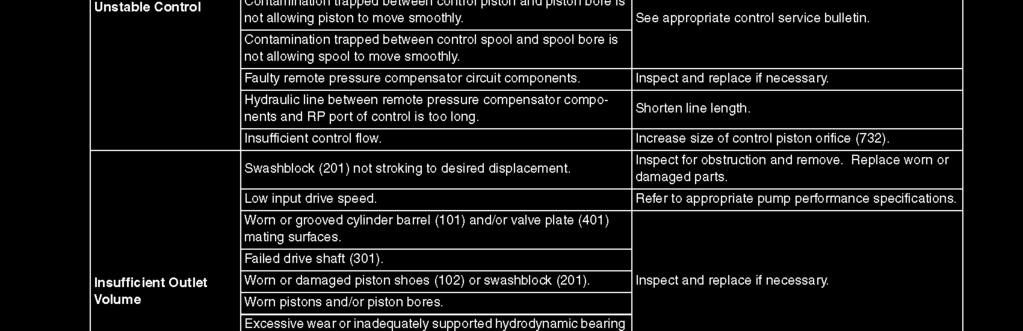
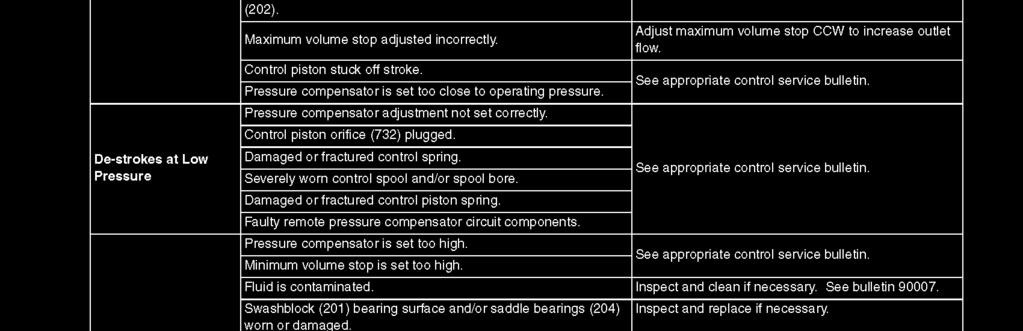
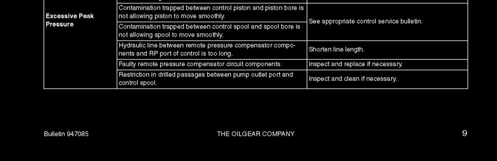
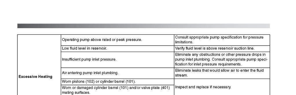
13 Model: 5B20 Hydraulic Power Unit 6.0 TROUBLESHOOTING 6.1 NO FLOW OR PRESSURE Flow control set too low:... Increase flow setting. Motor running in wrong direction:... See Section 3.0, "Preparation for Use". Insufficient oil in reservoir:... See Section 3.0, "Preparation for Use". Air in hydraulic lines:... See Section 4.4, "Bleeding Air From System". Faulty pump:... Repair or replace pump. 6.2 FLUCTUATING PRESSURE OR FLOW Air in hydraulic lines:... See Section 4.4, "Bleeding Air From System". 6.3 UNIT OVERHEATS Low fluid level in reservoir:... See Section 3.0, "Preparation for Use". Running unit for long time periods Cycle landing gear or other components without operating aircraft:... periodically or allow unit to cool components. Bypass valve partially open:... See Section 4.2.C, "Bypass Valve Operation". NOTE: Running time under deadhead condition can be increased substantially by selecting the "Hydraulic Power Unit" position; reservoir selector valve. When a pressure compensated pump is required to hold pressure without any flow delivery (dead headed condition), it is normal for the pump case drain flow and temperature to increase. By selecting the "Hydraulic Power Unit" position of the selector valve, all of the oil in the reservoir is utilized for cooling. 7.0 PARTS LIST INDEX When ordering Replacement Parts/Kits, please specify Model & Serial Number of your product. Reference the following for ordering information of Replacement Parts and Kits. Contents Page Bypass Valve Check Valve Control Module Electrical Components External Components HC-2161 Hand Pump Assembly Internal Hydraulic Hoses Hand Pump (Option M) Pressure Filter Pressure Relief Valve Pump/Motor Assembly Reservoir Assembly / Rev
14 Model: 5B20 Hydraulic Power Unit External Components ITEM PART NUMBER DESCRIPTION QTY 1... U Caster, Rigid H Latch HC Pyrometer (Option K) HC Gauge, Pressure EC Switch, On/Off EC Lamp, Replacement EC Hourmeter (Option E or F) H Handle HC Flowmeter HC-2150-A1 (Calibrated)... Flowmeter U Caster, Swivel H Lock, Floor TF * Hose, Return TF * Hose, Pressure Z Hanger, Hose HC Indicator, Sight Flow... 1 LOCATION Internal Hydraulic Hoses PART NUMBER Case Drain Cooler to Bypass Cooler... TF *32.0 Control Block to Bypass Cooler... TF *28.0 Pump to Case Drain Cooler... TF *22.5 Pump to Flow Meter... TF *30.0 Control Block to Pressure Gauge... TF *16.0 Control Block to Pressure Filter... TF *22.0 Cooler to Flow Indicator... TF * / Rev
15 Model: 5B20 Hydraulic Power Unit Electrical Components **When ordering replacement parts/kits, please specify model, serial number and color of your unit.** 1. Set Item 01 to "Manual" and set "A2" to its corresponding full load amps. ITEM PART NUMBER DESCRIPTION QTY 1... EC Relay, IEC Overload EC Enclosure, Electrical See Table... Contactor, IEC Motor See Table... Transformer EC Holder, Fuse EC Fuse... 1 ITEM 60 HZ Applications Description Qty. 3 EC-1838 EC-1838 EC-1838 EC-1836 EC-1837 Contactor, IEC Motor 1 4 EC EC-1074 EC EC-1074 EC Transformer 1 ITEM 50 HZ Applications Description Qty. 3 EC-1838 EC-1838 EC-1836 EC-1836 EC-1836 Contactor, IEC Motor 1 4 EC EC-1074 EC EC EC-1074 Transformer 1 07/ Rev
16 Model: 5B20 Hydraulic Power Unit Reservoir Assembly ITEM PART NUMBER DESCRIPTION QTY 1... HC Reservoir HC Filler, Breather HC Gauge, Sight H Washer, Nylon H Gasket, Cover HC Diffuser HC Strainer / Rev
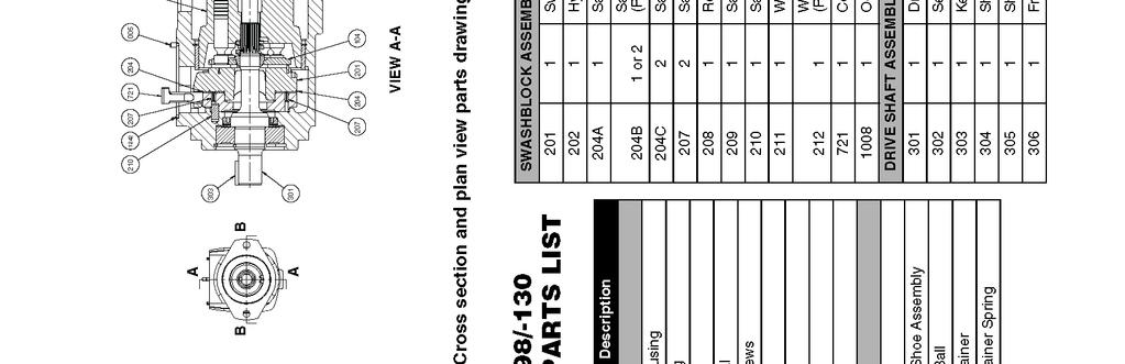
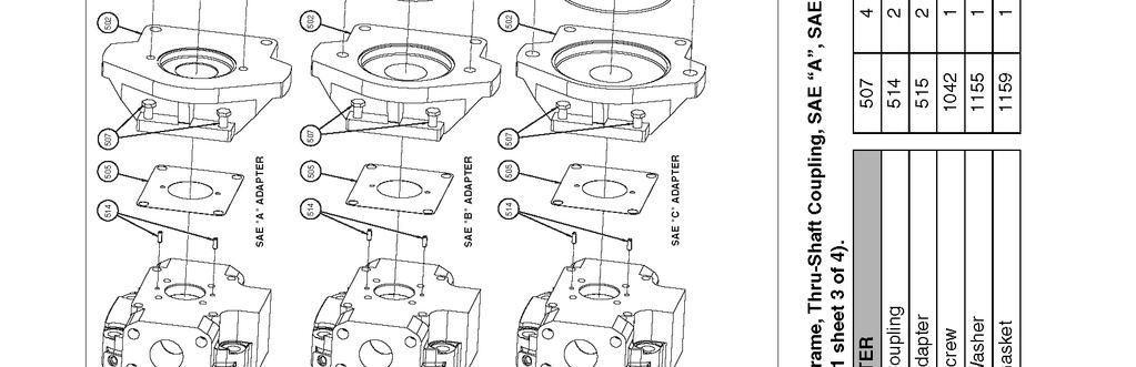
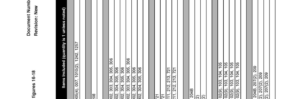
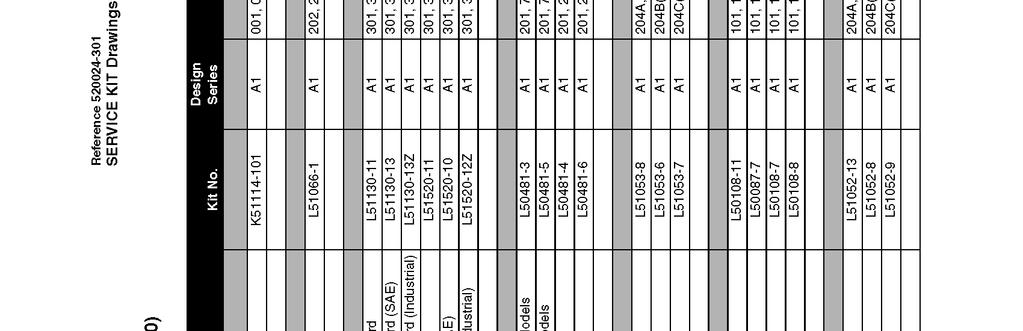
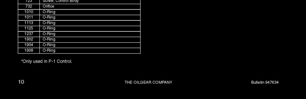
17 Model: 5B20 Hydraulic Power Unit Pump/Motor Assembly ITEM PART NUMBER DESCRIPTION QTY 1... HC Mount, Pump/Motor H Spider H Coupling, Body/Motor K Kit, Hydraulic Pump with Hardware H Coupling, Body/Pump... 1 PUMP REPLACEMENT PARTS Not Shown... TBD... Shaft Seal... 1 Not Shown... TBD... Gasket & O-rings Kit... 1 Note: All bolts are Grade 5. See the Pump Manufacturer's Service Booklet for servicing and additional kits. Kit includes HC-1543 Shaft Seal. 07/ Rev
18 Model: 5B20 Hydraulic Power Unit Pressure Filter ITEM PART NUMBER DESCRIPTION QTY 1... HC Assembly, Filter... 1 FILTER REPLACEMENT PARTS 2... K Filter Element Kit HC O-ring, Bowl... 1 Item 3 is included with Item 2. 07/ Rev
19 Model: 5B20 Hydraulic Power Unit Control Module ITEM PART NUMBER DESCRIPTION QTY 1... J Body, Valve HC Valve, Check HC Valve, Pressure Relief HC Valve, Bypass... 1 Bypass Valve ITEM PART NUMBER DESCRIPTION QTY 1... HC Assembly, Bypass Valve HC Handle, Valve HC O-ring HC Ring, Backup HC O-ring HC O-ring / Rev
20 Model: 5B20 Hydraulic Power Unit Pressure Relief Valve ITEM PART NUMBER DESCRIPTION QTY 1... HC Valve, Pressure Relief HC O-ring HC O-ring HC Ring, Backup... 1 Check Valve ITEM PART NUMBER DESCRIPTION QTY 1... HC Valve, Check HC O-ring HC O-ring HC Ring, Backup / Rev
21 Model: 5B20 Hydraulic Power Unit Option M Reservoir Fill Hand Pump ITEM PART NUMBER DESCRIPTION QTY 1... TF * Hose HC Assembly, Filter K Kit, Replacement Filter Element TF * Hose HC Assembly, 500 psi, Hand Pump TF * Hose Z Weldment, Filter Bracket H Handle, Pump... 1 See Pages 18 & 19 for additional Information. 07/ Rev
22 Model: 5B20 Hydraulic Power Unit HC-2161 (Mineral Base Fluids) Hand Pump 07/ Rev
23 Model: 5B20 Hydraulic Power Unit HC-2161 (Mineral Base Fluids) Hand Pump ITEM FLUID PART NUMBER DESCRIPTION QTY 3... N/A Clevis Pin Assembly N/A Tie Rods N/A Retaining Flange N/A Tube N/A Piston N/A Valve Block N/A... Reference Only... Available only in Assembly N/A... CXD Body N/A T... Retainer Mineral Base... 5M2-B T... Screw Release N/A Plug N/A Pivot... 1 Mineral Base SRK-PSB-120 Kit, O-ring; consists of: 8... Mineral Base O-ring, BUNA Mineral Base O-ring, BUNA Mineral Base O-ring, BUNA Mineral Base O-ring, BUNA... 1 SRK-PHR-120 Kit, Check Ball/Spring; consists of: N/A Intake Check Ball N/A Outlet Check Spring N/A Outlet Check Ball N/A Intake Check Spring... 1 SRK-PL-000T Kit, Bracket; consists of: N/A Linkage Pin Assembly N/A Strap N/A Bracket Handle T Kit, Handle; consists of: Not Shown... N/A Handle Grip... 1 Not Shown... N/A Handle / Rev
24
25 APPENDIX I Instrument Certification Notice
26
27 Instrument Certification Notice The gauge Certificates of Calibration supplied for the gauge(s) on this unit contain the calibration data for the actual instrument calibrated, along with the calibration date of the STANDARD used to perform the calibration check. The due date for re-calibration of the instrument should be based upon the date the instrument was placed in service in your facility. Re-calibration should be done on a periodic basis as dictated by the end user's quality system or other overriding requirements. Note that Tronair, Inc. does not supply certificates of calibration on flow meters or pyrometers unless requested at the time of placed order. These instruments are considered reference indicators only and are not critical to the test(s) being performed on the aircraft Eber Rd Tronair, Inc. Phone: (419) Holland, OH USA sales@tronair.com Fax: (419)
28
29 APPENDIX II Lincoln Motor Manual
30
31
32
33
34
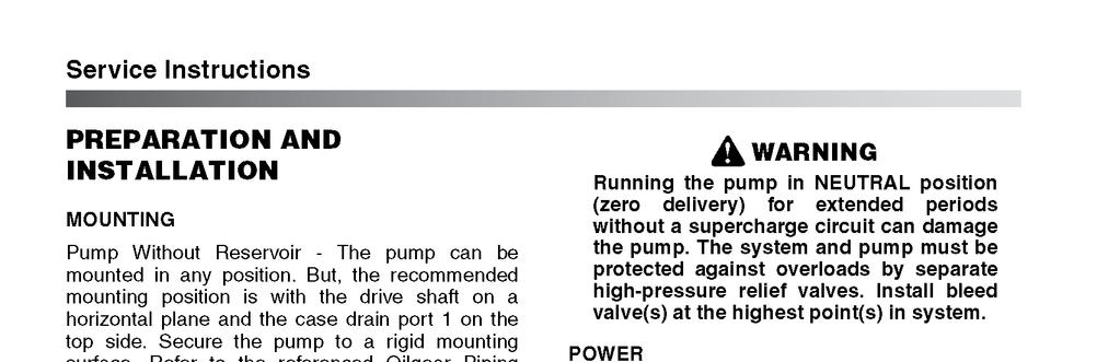
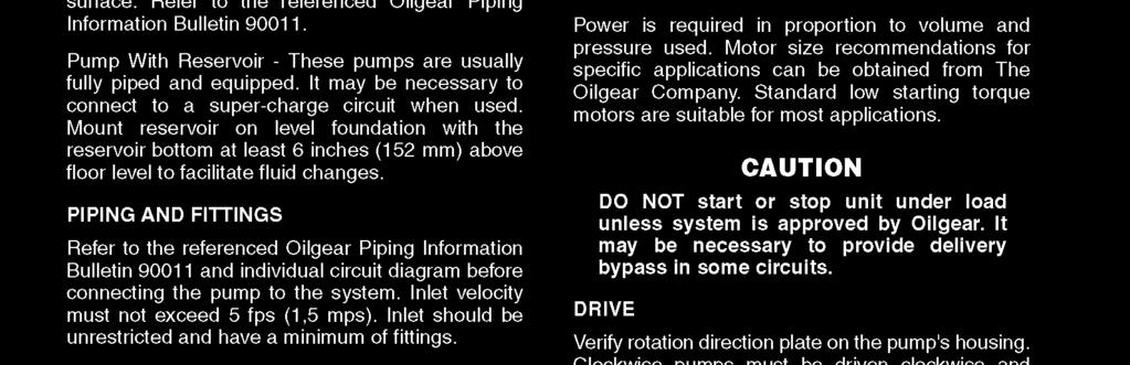
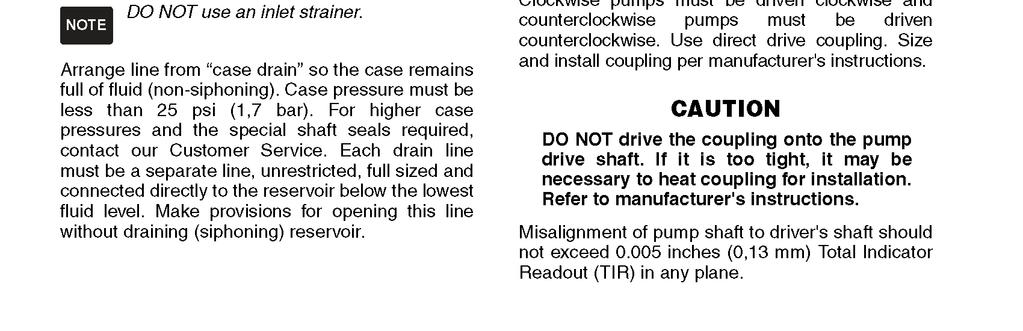
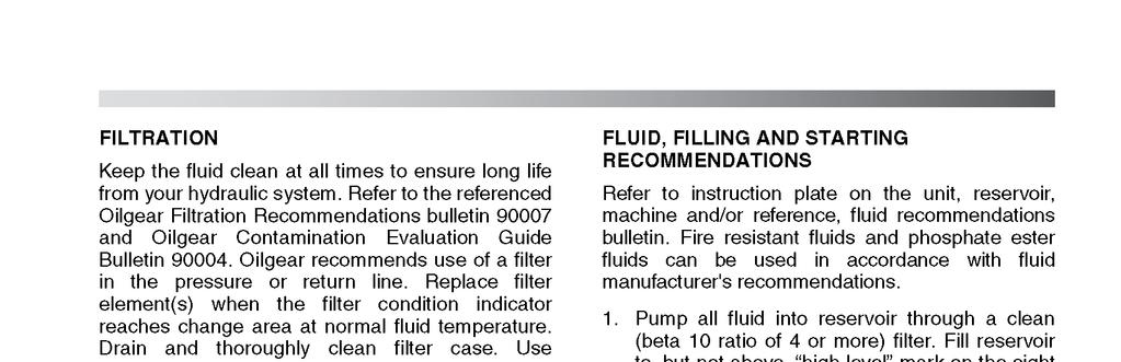
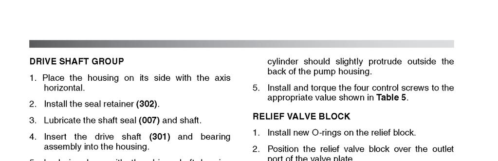
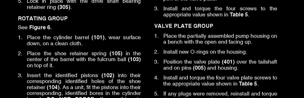
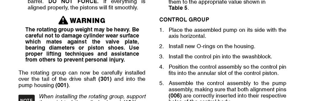
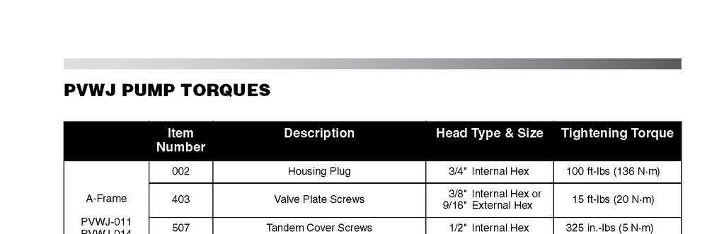
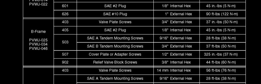
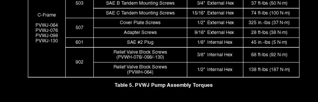
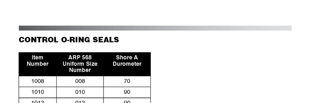
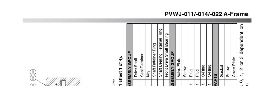
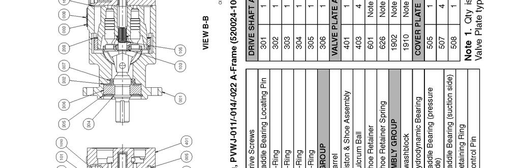
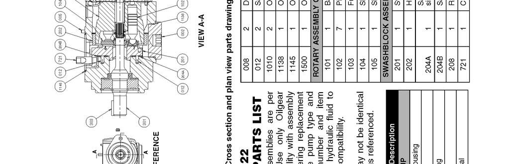
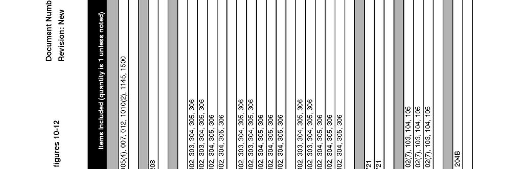
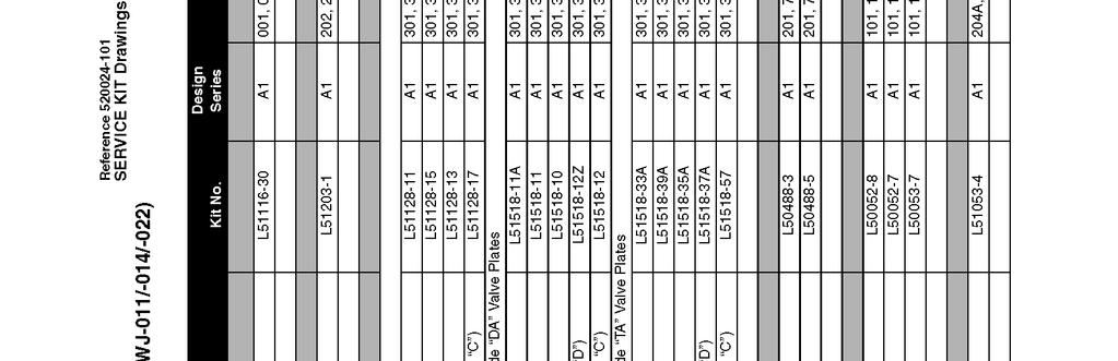
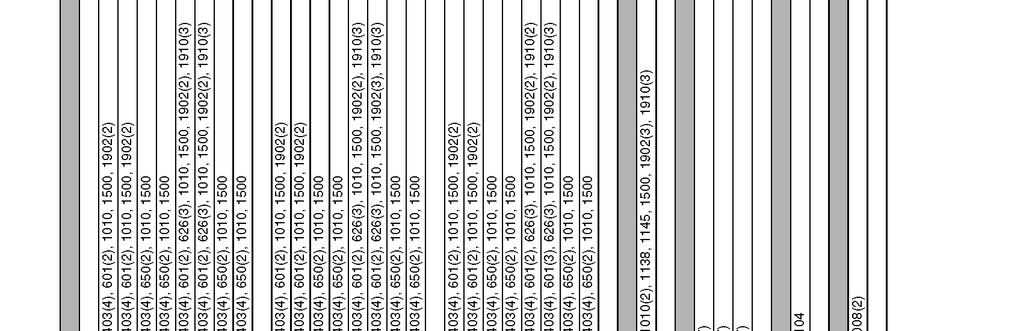
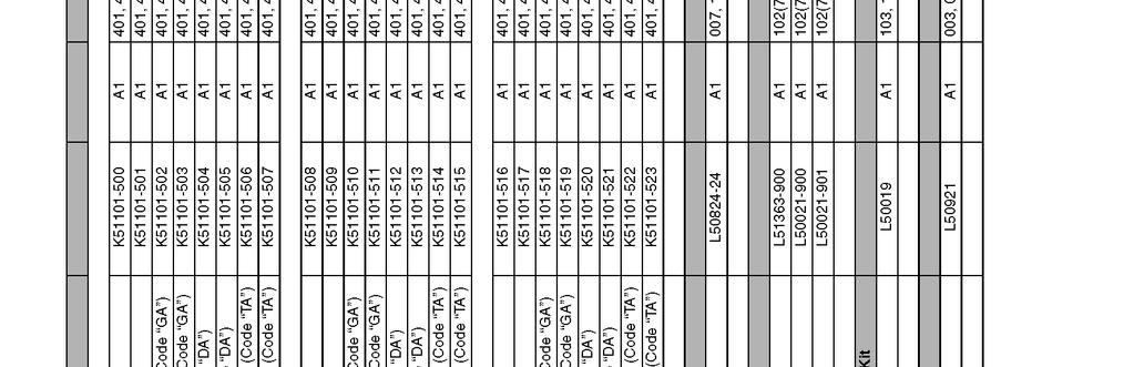
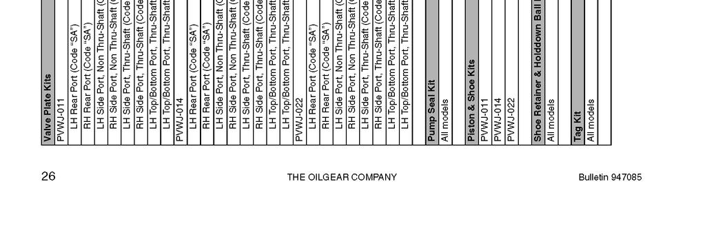
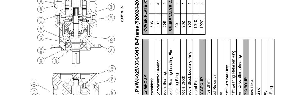
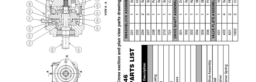
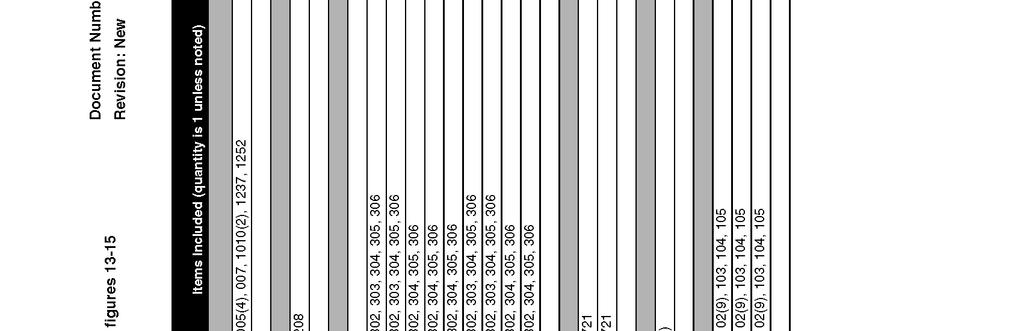
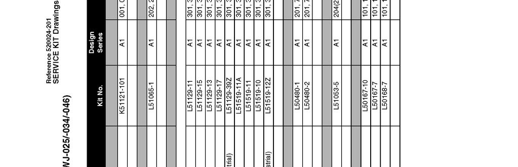
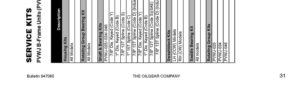
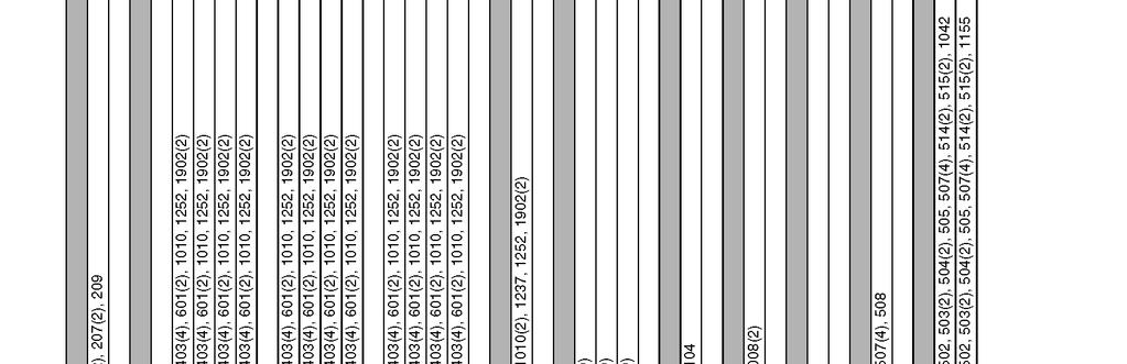
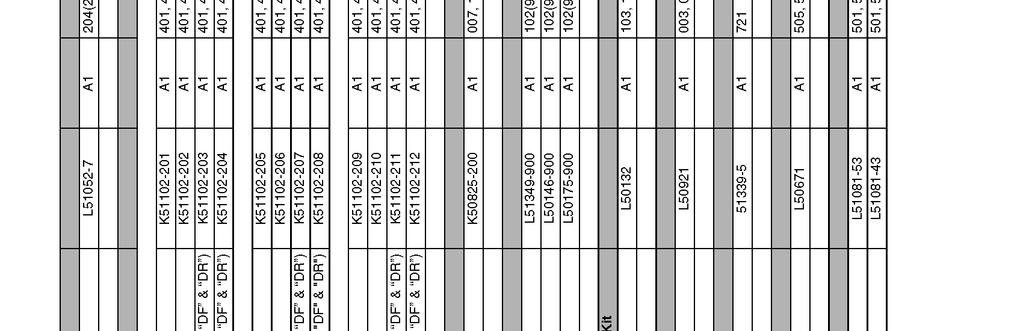
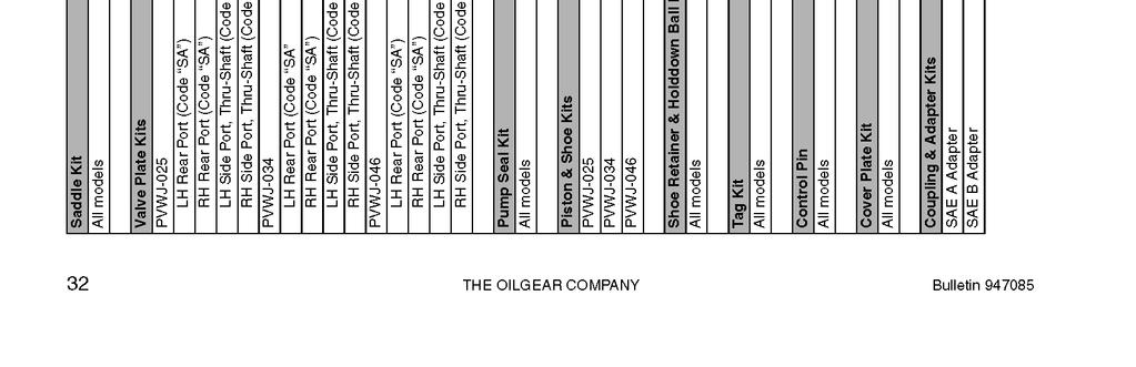
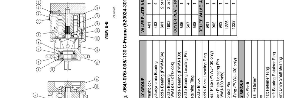
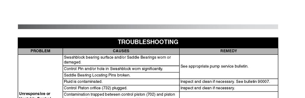
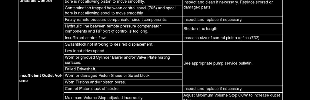
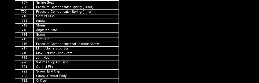
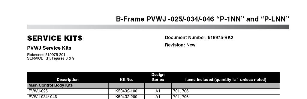
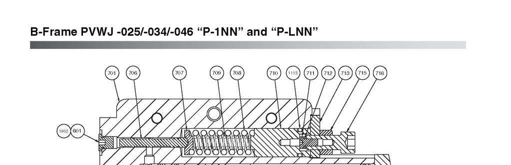
35 APPENDIX III Oilgear Type PVWJ Pump Manuals
36
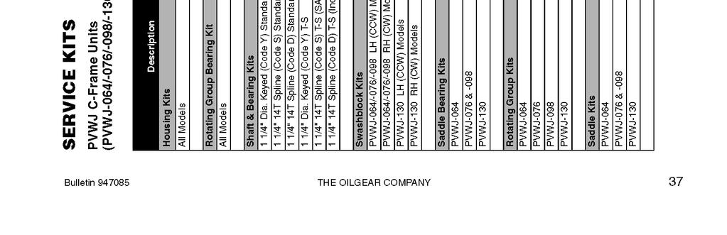
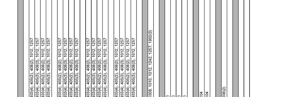
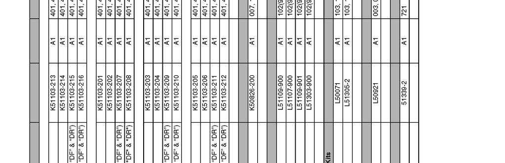
37
38

39
40
41
42
43
44
45
46


47


48
49
50


51
52
53
54
55


56
57
58
59
60

61
62

63
64
65
66
67
68


69
70
71
72
73
74
75

76
77
78
79
80
81
82
83
84
85
86
87
88
89
90
91
92
93

94
95

96
97
98
99
100

101

102
103
104
105


106
107
108
109 APPENDIX IV MSDS Hydraulic Fluid
110
111
112
113
114
115
116
117
Operation & Service Manual
 Operation & Service Manual Model: 5010 Hydraulic Power Unit 05/2004 - Rev. 01 Includes Illustrated Parts Lists 1740 Eber Rd Tronair, Inc. Phone: (419) 866-6301 Holland, OH 43528-9794 www.tronair.com 800-426-6301
Operation & Service Manual
 Operation & Service Manual Model: 06-4035-3600 Hydraulic Service Unit 03/2003 AA Rev. 15 Includes Illustrated Parts List Tronair, Inc. 1740 Eber Road Holland, Ohio 43528-9794 USA Telephone: (419) 866-6301
Operation & Service Manual
 Operation & Service Manual Technical Manual Model: 02-7813C0100 12 Ton (10.8 Metric Ton) Two Stage Hydraulic Axle Jack 06/2006 Rev. OR Includes Illustrated Parts List Tronair, Inc. 1740 Eber Road Holland,
Operation & Service Manual
 Operation & Service Manual Model: 02-1248-0112 12 Ton Single Stage Jack 11/2004 Rev. 02 Includes Illustrated Parts Lists 1740 Eber Rd Tronair, Inc. Phone: (419) 866-6301 Holland, OH 43528-9794 www.tronair.com
Operation & Service Manual
 Operation & Service Manual Model: 08-4048-0013 05/2008 - Rev. 01 Includes Illustrated Parts List 1740 Eber Rd Tronair, Inc. Phone: (419) 866-6301 Holland, OH 43528-9794 www.tronair.com 800-426-6301 USA
Operation & Service Manual
 Operation & Service Manual Model: 08-4049-1012 Includes Illustrated Parts Lists Tronair, Inc. 1740 Eber Road Holland, Ohio 43528-9794 USA Telephone: (419) 866-6301 800-426-6301 Fax: (419) 867-0634 Web
OPERATION & SERVICE MANUAL
 OPERATION & SERVICE MANUAL Models: 06-5020 Series 08/2009 - Rev. 12 Tronair, Inc. Phone: (419) 866-6301 800-426-6301 1 Air Cargo Pkwy East Web: www.tronair.com Swanton, OH 43558 Email: sales@tronair.com
OPERATION & SERVICE MANUAL
 OPERATION & SERVICE MANUAL Model: 07-3000-1921 Defueler 06/2007 Rev. 07 Tronair, Inc. Phone: (419) 866-6301 800-426-6301 1 Air Cargo Pkwy East Web: www.tronair.com Swanton, OH 43558 Email: sales@tronair.com
Operation & Technical Manual. Model: Ground Test Motor
 Operation & Technical Manual Model: 13-6604-6600 Ground Test Motor 05/2009 Rev. 05 Includes Illustrated Parts Lists DEVELOPED IN CONJUNCTION WITH HAMILTON-SUNDSTRAND 1740 Eber Rd Tronair, Inc. Phone: (419)
XCITE Owner s Manual. Reso-not TM Damping System XCITE 1502C HYDRAULIC POWER SUPPLY
 Reso-not TM Damping System XCITE Owner s Manual 1502C HYDRAULIC POWER SUPPLY Xcite Systems Corporation 675 Cincinnati RDS Batavia - 1 Pike Cincinnati, Ohio 45245 Tel: (239) 980-9093 Fax: (239) 985-0074
Model: TON AXLE JACK. March 1999 Rev.-02
 Model: 02-7832-0100 March 1999 Rev.-02 TABLE OF CONTENTS PAGE 1.0 DESCRIPTION1 2.0 USAGE... 1 3.0 SPECIFICATIONS... 1 4.0 ASSEMBLY INSTRUCTIONS... 1 4.1 General Information... 1 4.2 Pre-Use Checks... 1
UNIVERSAL, INDEPENDENT DUAL SYSTEM HYDRAULIC TEST STAND
 UNIVERSAL, INDEPENDENT DUAL SYSTEM HYDRAULIC TEST STAND Our Competent Engineering Staff Ensures You are Provided with the Exact Hydraulic Testing Equipment for Current and Future Applications Which Will
Air / Hydraulic Under Axle Jack
 655 Eisenhower Drive Owatonna, MN 55060-0995 USA Phone: (507) 455-7000 Tech. Serv.: (800) 533-6127 Fax: (800) 955-8329 Order Entry: (800) 533-6127 Fax: (800) 283-8665 International Sales: (507) 455-7223
Tronair, Inc. Phone: (419) Air Cargo Pkwy East Web:
 Air Cargo Pkwy East Web:") This product can not be modified without the written approval of Tronair, Inc. Any modifications done without written approval voids all warranties and releases Tronair, Inc., it suppliers, distributors,
This product can not be modified without the written approval of Tronair, Inc. Any modifications done without written approval voids all warranties and releases Tronair, Inc., it suppliers, distributors,
R & D SPECIALTIES ROTROL I USER'S MANUAL
 R & D SPECIALTIES ROTROL I USER'S MANUAL TABLE OF CONTENTS INTRODUCTION...2 SPECIFICATIONS...2 CONTROLS AND INDICATORS...3 TIME DELAYS...4 INSTALLATION...5 SYSTEM OPERATION...9 TROUBLESHOOTING...13 OPTIONAL
Model Ton Hand Carry Axle Jack P/N: CJ67D0250-1
 Model 1504-50 15 Ton Hand Carry Axle Jack P/N: CJ67D0250-1 Operation and Maintenance Manual with Illustrated Parts List 2222 South Third Street Columbus, Ohio 43207-2402 Phone (614) 443-7492 FAX (614)
OFX7 Operating Maintenance and Troubleshooting Manual L-4219
 OFX7 Operating Maintenance and Troubleshooting Manual L-4219 L-2999 Created 9.2012 User Manual OFX7 L-4219 - Table of Contents - Preface. 4 Customer Service. 4 Modifications to the Product 4 Warranty.
COMPACTOR & RAM ASSEMBLY
 P1 P2 COMPACTOR & RAM ASSEMBLY FOR MODELS - ALL 5/02 Item Part Number Part Description Qty. 1 64--129 1--1/2 STD. Flat Washer 10 2 9121--1--8 Cylinder Pin, Base 1 3 60--608 1/4 DIA. x 2--1/2 Roll Pin --
COVER PLATES & ROLLERS
 COVER PLATES & ROLLERS 9035-10 Revised 8/95 FOR MODELS - ALL 3/98 Item Part Number Part Description Qty. 1 9035--1--10 Top Cover Plate 1 2 62--425 3/8NC x 3/4 Hex Washer Thread Cutting Screw 8 3 62--544
WARCO CHEMAG SERIES GH FILTERS
 WARCO CHEMAG SERIES GH FILTERS High Performance Pleated & Bag Type Filtration Systems INSTALLATION, OPERATION, AND MAINTENANCE INSTRUCTIONS Thank you for your purchase of a WARCO Series GH Filtration System.
TIN KNOCKER TK H1652 Hydraulic Shear
 TIN KNOCKER TK H1652 Hydraulic Shear INSTRUCTIONS & PARTS DIAGRAM TAAG INDUSTRIES CORP. 1550 SIMPSON WAY, ESCONDIDO, CA 92029 Tel: (800) 640-0746 Fax: (760) 727-9948 Website: www.tinknocker.com Email:
FLUID HANDLING: Drum Filter Cart
 FLUID HANDLING: Drum Filter Cart This cart is ideal for pre-cleaning, protecting, and transferring oil from a conveniently attachable, secured drum. A drum adapter kit with a desiccant breather is included
FLUID HANDLING: Drum Filter Cart
 FLUID HANDLING: Drum Filter Cart This cart is ideal for pre-cleaning, protecting, and transferring oil from a conveniently attachable, secured drum. A drum adapter kit with a desiccant breather is included
Hydrostatic Drive. 1. Main Pump. Hydrostatic Drive
 Hydrostatic Drive The Hydrostatic drive is used to drive a hydraulic motor at variable speed. A bi-directional, variable displacement pump controls the direction and speed of the hydraulic motor. This
Routine Compressor Maintenance
 Establishing a regular, well-organized maintenance program and strictly following it is critical to maintaining the performance of a compressed air system. One person should be given the responsibility
Hydraulic Pump Troubleshooting P & BDP Series Models
 Hydraulic Pump Troubleshooting P & BDP Series Models Hydraulic Pump damage can cause traction circuit failures and problematic hydraulic system contamination. Performance problems such as weak traction
Standard Power Units Start-Up and Maintenance
 Standard Power Units Start-Up and Maintenance Value-Pak System-Pak System Pak-Plus Low-Pak System-Center System-L System-Overhead Table of Contents General Information....................................................................
Trouble Shooting Guide EWA, 3-phase (D2422)
") Trouble Shooting Guide EWA, 3-phase (D2422) Trouble Shooting Guide Problem Possible Cause Possible Remedy Unit does not start Breaker tripped, no power to unit Loose wire Defective contactor or coil Close
Trouble Shooting Guide EWA, 3-phase (D2422) Trouble Shooting Guide Problem Possible Cause Possible Remedy Unit does not start Breaker tripped, no power to unit Loose wire Defective contactor or coil Close
Hydraulic Immediate Need Power Pack
 Safety, Operation, and Maintenance Manual WARNING Improper use of this tool can result in serious bodily injury This manual contains important information about product function and safety. Please read
QGD-20/25/30 & QGD-40/50
 QGD-0/5/0 & QGD-40/50 Direct Drive Rotary Screw Air Compressor Parts Manual This manual contains important safety information and should be made available to all personnel who operate and/or maintain this
Hydraulic Projects Ltd
 Hydraulic Projects Ltd PC45 Constant Running Marine Autopilot Hydraulic Pump Installation and Service Instructions Serial Number Engineering Excellence FORM_PC45 ISS.4 Released\11 Data Sheets & Manuals\Manuals\Customer
COVER PLATES & ROLLERS
 COVER PLATES & ROLLERS FOR MODELS - ALL 8/01 Item PartNumber Part Description Qty. 1 9017--104--35 Stop 2 2 62--108 3/8NC x 1 GD5 Cap Screw 2 3 62--425 3/8NC x 3/4 GD8 Hex Washer Thread Forming Screw 8
Operating Manual. High Performance Vacuum Pump Models and 15600
 Operating Manual High Performance Vacuum Pump Models 15400 and 15600 CoolTech High Performance Vacuum Pumps Congratulations on purchasing one of Robinair s top quality CoolTech vacuum pumps. Your pump
Maximum operating temperature for standard motors = 110 C. Shut down temperature in case of a malfunction = 115 C.
 Section 3 Maintenance & Troubleshooting General Inspection Lubrication & Bearings Type of Grease WARNING: UL rated motors must only be serviced by authorized Baldor Service Centers if these motors are
JARVIS. Model 30CL-1 AND 30CL-3 Hock Cutter and Dehorner. 30CL-1 Hock Cutter
 Model 30CL-1 AND 30CL-3 Hock Cutter and Dehorner 30CL-1 Hock Cutter with Leg Grabber 30CL-1 Hock Cutter 30CL-3 Dehorner Equipment Selection 30CL-1 Sheep Head Dropper Order Number 30CL-1 Hock Cutter 30CL-1
Electric Airless Sprayers Operating Instructions
 Electric Airless Sprayers Operating Instructions 309365 Rev. A 3000 psi (210 bar, 21 MPa) Maximum Working Pressure How To Perform: Component Identification....... 3 Setup........................... 4 Startup..........................
Racing Jack Max. Capacity: 3,000 lbs. (1,361 kg)
") R SPX Corporation 655 Eisenhower Drive Owatonna, MN 55060-0995 USA Phone: (507) 455-7000 Tech. Serv.: (800) 533-6127 Fax: (800) 955-8329 Order Entry: (800) 533-6127 Fax: (800) 283-8665 International Sales:
R SPX Corporation 655 Eisenhower Drive Owatonna, MN 55060-0995 USA Phone: (507) 455-7000 Tech. Serv.: (800) 533-6127 Fax: (800) 955-8329 Order Entry: (800) 533-6127 Fax: (800) 283-8665 International Sales:
TT-12 OWNERS MANUAL/PARTS LIST
 TOPLIFTER Tailgates By THIEMAN TT-12 OWNERS MANUAL/PARTS LIST SHOWN WITH OPTIONAL 2 PC. ALUMINUM PLATFORM! IMPORTANT! KEEP IN VEHICLE! PLEASE READ AND UNDERSTAND THE CONTENTS OF THIS MANUAL BEFORE OPERATING
Premium Supply. Direct Push. Models PCK-3530-DP PCK DP PCK-530-DP. Operator s Manual and Installation Instructions
 Direct Push Models PCK-3530-DP PCK-3530-2DP PCK-530-DP Operator s Manual and Installation Instructions Premium Supply 2038 West Interstate 30 866-934-0777 Proud members of: and June 20, 2018 Table of Contents
Low Profile J Series Power Unit with Vane Pump
 Low Profile J Series Power Unit with Vane Pump READ ALL INSTRUCTIONS CAREFULLY BEFORE ATTEMPTING TO ASSEMBLE, INSTALL, OPERATE OR MAINTAIN THE PRODUCT DESCRIBED. PROTECT YOURSELF AND OTHERS BY OBSERVING
MODEL 10LH SPECIFICATION
 MODEL 10LH SPECIFICATION 1.0 General Specifications There will be furnished one (1) only Grind Hog TM Model 10LH Comminutor as manufactured by G.E.T. Industries, Inc. Rotation shall be in a clockwise (standard)
Tailgates By THIEMAN WT20, 30 & 40 PLEASE READ AND UNDERSTAND THE CONTENTS OF THIS MANUAL BEFORE OPERATING THE EQUIPMENT. HIEMAN
 WEIGHTLIFTER Tailgates By THIEMAN WT20, 30 & 40 OWNERS MANUAL/PARTS LIST! IMPORTANT! KEEP IN VEHICLE! PLEASE READ AND UNDERSTAND THE CONTENTS OF THIS MANUAL BEFORE OPERATING THE EQUIPMENT. NATIONAL TRUCK
Operating instructions Form no safety definitions
 Operating instructions Form no. 1000437 safety definitions safety symbols are used to identify any action or lack of action that can cause personal injury. Your reading and understanding of these safety
PAGE 1. TES Operation & Testing Guidelines: Tes Trouble shooting
 PAGE 1 This document outlines questions to ask and components to check during TES troubleshooting. More detailed troubleshooting procedures are available in the TES Troubleshooting Guide. 1. Flow Light
PRODUCT NUMBERING SYSTEM SERIES PHASE. 1: Single Phase 3: Three Phase
 TABLE OF CONTENTS Product Numbering System and Specifications... Safety... Receiving and Inspection... Installation... Electrical...6 Start-up...7 INTRODUCTION The compressor you have purchased is a combination
Wash Prep Systems featuring CAT PUMPS DUPM623 DUPM820 / DUPM820-TS DUPM820D / DUPM820D-TS DUPM1010. Owner s Manual #
 Wash Prep Systems featuring CAT PUMPS DUPM623 DUPM820 / DUPM820-TS DUPM820D / DUPM820D-TS DUPM1010 Serial Number: Owner s Manual #0779 072415 Installation Date: Please read and understand this manual.
PARTS LIST FOR CW ME3 (AFTER SERIAL # )
") PARTS LIST FOR CW-5004-0ME3 (AFTER SERIAL #10235166) Motor Horsepower: 15 HP Pump Oil Grade: Mi-T-M Pump Oil #AW-4085-0016 Pump Oil Capacity: 31.0 oz. Nozzle Size: 3.5 This Parts Listing has been compiled
PARTS LIST FOR CW-5004-0ME3 (AFTER SERIAL #10235166) Motor Horsepower: 15 HP Pump Oil Grade: Mi-T-M Pump Oil #AW-4085-0016 Pump Oil Capacity: 31.0 oz. Nozzle Size: 3.5 This Parts Listing has been compiled
GLYCOL FEED SYSTEMS OPERATION & MAINTENANCE MANUAL
 GLYCOL FEED SYSTEMS OPERATION & MAINTENANCE MANUAL PLEASE RECORD THE FOLLOWING DATA (Information is located on the product label or packing slip) Model Number: Date Code: Installation Date: Installation
DODGE COOL LUBE 2 for Sleevoil Pillow Blocks Part Numbers , , ,
 DODGE COOL LUBE for Sleevoil Pillow Blocks Part s 063487, 063488, 07889, 07890 These instructions must be read thoroughly before installing or operating this product. WARNING: To ensure the drive is not
8650 Enterprise Drive, Peosta IA / Fax PARTS LIST FOR JP ME1/0ME3
 8650 Enterprise Drive, Peosta IA 52068 563-556-7484 / Fax 563-556-1235 PARTS LIST FOR JP-3004-0ME1/0ME3 Motor Horsepower: 8 H.P. Pump Oil Grade: Mi-T-M Pump Oil #AW-4085-0016 Pump Oil Capacity: 18.5 oz.
Troubleshooting WARNING
 Troubleshooting WARNING Before troubleshooting or attempting to service, read the following safety rules to avoid accidental exposure to chemical and also risk of electric shock. Note: A reserve, clean
OPERATION AND SERVICE MANUAL. McGILL UNIVERSITY PROJECT: MCS-3237 SUBJECT: HYDRAULIC POWER UNIT AND ROTARY ACTUATORS DECEMBER 2001
 OPERATION AND SERVICE MANUAL McGILL UNIVERSITY PROJECT: MCS-3237 SUBJECT: HYDRAULIC POWER UNIT AND ROTARY ACTUATORS DECEMBER 2001 CONTENTS 1. DESCRIPTION OF HYDRAULIC COMPONENTS... 3 1.1. HYDRAULIC POWER
8650 Enterprise Drive, Peosta IA / Fax PARTS LIST FOR JP ME1/0ME3
 8650 Enterprise Drive, Peosta IA 52068 563-556-7484 / Fax 563-556-1235 PARTS LIST FOR JP-2503-0ME1/0ME3 Motor Horsepower: 6 H.P. Pump Oil Grade: Mi-T-M Pump Oil #AW-4085-0016 Pump Oil Capacity: 18.5 oz.
MID RISE. INSTALLATION and OPERATION MANUAL MODEL 6000A // 6000E 6,000 LB. CAPACITY. READ and SAVE THIS INSTRUCTION MANUAL
 INSTALLATION and OPERATION MANUAL MID RISE MODEL 6000A // 6000E 6,000 LB. CAPACITY READ and SAVE THIS INSTRUCTION MANUAL AUGUST 2005 6-0944 6500 Millcreek Drive Mississauga, Ontario Canada L5N 2W6 1-800-268-7959
C T h e A d va n t a g e
 C The Advantage TABLE OF CONTENTS Introduction...1 Product Numbering System...1 Safety...2 Receiving and Inspection...2 Installation...2 Electrical...3 Parts Identification...7 Lubrication...9 Start-up...10
MIDRISE MODEL SM60F_1 // SM60F_A 6,500 LB. CAPACITY
 INSTALLATION and OPERATION MANUAL READ THIS INSTRUCTION MANUAL THOROUGHLY BEFORE INSTALLING, OPERATING, SERVICING OR MAINTAINING THE LIFT. SAVE THIS MANUAL. NOV 2007 REV.B MIDRISE MODEL SM60F_1 // SM60F_A
CW ME1/3 CW ME1/3 CW ME3:
 8650 Enterprise Drive, Peosta IA 52068 563-556-7484 / Fax 563-556-1235 PARTS LIST FOR CW-2405-4ME1/3 CW-3004-4ME1/3 CW-3006-4ME3 Motor Horsepower: CW-2405/3004-4ME1/3: 7.5HP CW-3006-4ME3: 15 HP Pump Oil
60Hz UP6 15, UP6 20, UP6 25, UP6 30
 60Hz UP6 15, UP6 20, UP6 25, UP6 30 en fr pt es PARTS CATALOGUE CATALOGUE DE PIÈCES DÉTACHÉES LISTA DE PEÇAS LISTA DE REPUESTOS zh C.C.N : 80445166 REV. : A DATE : OCTOBER 2008 CONTENTS Page T N o Page
P844L3MS For Models: NL844L3.1MS1 and NL844L3.1MS2 PARTS CATALOG. Marine Generators Marine Diesel Engines Land-Based Generators
 P844L3MS For Models: NL844L3.1MS1 and NL844L3.1MS2 PARTS CATALOG Marine Generators Marine Diesel Engines Land-Based Generators CALIFORNIA Proposition 65 Warning: Diesel engine exhaust and some of its constituents
6L Oil-less Air Compressor 53103
 6L Oil-less Air Compressor 53103 Operating Instructions Please read and save these instructions before attempting to assemble, install, operate or maintain the product. Protect yourself and others by observing
PE 20 SERIES ELECTRIC POWER PUMPS
 A Division Of Templeton, Kenly & Co., Inc. PE 20 SERIES ELECTRIC POWER PUMPS Operating Instructions Manual For 1/2 hp, 115 Volt and 230 Volt PEM, PPM, PES and PPS Models Revison B 07/2006 2525 Gardner
Users Manual Professional Series Direct Drive Pump.25-2 GPM Series Safety, Operating, Installation, and Maintenance Instructions
 Users Manual Professional Series Direct Drive Pump.25-2 GPM Series Safety, Operating, Installation, and Maintenance Instructions 600 S 56 th Street #9 Chandler, AZ 85226 Phone: 480-507-6478 Fax: 480-838-2232
Portable Filter Carts Models 5MF and 10MF
 s Models 5MF and 10MF 161 Applications for Parker Filter Carts Filtering new fluid before putting into service Transferring fluid from drums or storage tanks to system reservoirs Conditioning fluid that
Hydraulic Maintenance & Troubleshooting. Content - Norman Kronowitz Presenter Jim Trinkle
 Hydraulic Maintenance & Troubleshooting Content - Norman Kronowitz Presenter Jim Trinkle Introduction Welcome to the CMA/Flodyne/Hydradyne s Hydraulic Troubleshooting presentation. We will introduce many
Dodge Cool Lube 2 for Sleevoil Pillow Blocks Part Numbers , , ,
 Dodge Cool Lube for Sleevoil Pillow Blocks Part Numbers 063487, 063488, 07889, 07890 These instructions must be read thoroughly before installation or operation. This instruction manual was accurate at
TDR-44, 55, 66 OWNERS MANUAL/PARTS LIST
 TDR SERIES Railgates By THIEMAN TDR-44, 55, 66 OWNERS MANUAL/PARTS LIST! IMPORTANT! KEEP IN VEHICLE! PLEASE READ AND UNDERSTAND THE CONTENTS OF THIS MANUAL BEFORE OPERATING THE EQUIPMENT. NATIONAL TRUCK
Troubleshooting the Transmission Hydraulic System
 Testing and Adjusting IT28F INTEGRATED TOOLCARRIER POWER TRAIN Testing And Adjusting Introduction Reference: For Specifications with illustrations, refer to SENR5974, IT28F Integrated Toolcarrier Power
SUPER DUTY, INDEPENDENT DUAL SYSTEM HYDRAULIC POWER UNIT / DIESEL POWERED
 SUPER DUTY, INDEPENDENT DUAL SYSTEM HYDRAULIC POWER UNIT / DIESEL POWERED Designed to Meet or Exceed Standards Set By National Stock Number Specifications 2 Year Warranty Model 05-514-03 Electric Motor
LED Exam Light. Service and Parts Manual. Model Numbers: FOR USE BY MIDMARK TRAINED TECHNICIANS ONLY Rev. (1/23/18)
") LED Exam Light Model Numbers: 253 Service and Parts Manual FOR USE BY MIDMARK TRAINED TECHNICIANS ONLY 004-0779-00 Rev. (1/23/18) Table of Contents Section C Section B Section A General Info GENERAL INFORMATIOn
LED Exam Light Model Numbers: 253 Service and Parts Manual FOR USE BY MIDMARK TRAINED TECHNICIANS ONLY 004-0779-00 Rev. (1/23/18) Table of Contents Section C Section B Section A General Info GENERAL INFORMATIOn
Models
 Models 15300 15301 15500 15501 SAFETY PRECAUTIONS WARNING! To prevent personal injury, Wear goggles when working with refrigerants. Contact with refrigerants may cause injury. Incorrect use or connections
AQUIS Foam System. Installation, Operation, and Maintenance Instructions AQUIS 1.5, AQUIS 3.0, and AQUIS 6.0
 Form Number: F-1031 Issue Date: Aug 1, 2017 Section: 2447 Revision Date: Sept 7, 2018 AQUIS Foam System Installation, Operation, and Maintenance Instructions AQUIS 1.5, AQUIS 3.0, and AQUIS 6.0 Waterous
COMPACT WHEEL LOADERS PIN and after 6018BH - PIN and after 6020L, 6020BH Parts Catalog
 R Ingersoll HOME COMPACT WHEEL LOADERS 6018 - PIN 14190349 and after 6018BH - PIN 14190351 and after 6020L, 6020BH Parts Catalog 8-3360 TRACTORS ATTACHMENTS INDEX PAINT ENGINES GENERAL INFO MAIN INDEX
Liftgate Terminology
 SL-20 Series SL-20 Series Click the appropriate link below for the major component of the liftgate for which you are trying to find the correct part. If you are unsure of the name of the part in Waltco
Eclipse GEN 2.0 CAFSystem, Model 150-ECL CAFS PTO Kit Installation Instructions
 Eclipse GEN 2.0 CAFSystem, Model 150-ECL CAFS PTO Kit Installation Instructions Read Read through the the safety installation information instructions overhaul carefully instructions before carefully beginning
Fluid Maintenance. The hydraulic oil performs four functions in the hydraulic system:
 The hydraulic oil performs four functions in the hydraulic system: Transmits Energy Coolant Lubricant Sealant Viscosity Viscosity is the rating of the oil thickness or resistance to flow. Viscosity is
AIR COMPRESSOR OPERATING INSTRUCTION AND PARTS LIST
 AIR COMPRESSOR OPERATING INSTRUCTION AND PARTS LIST BELT TYPE IMPORTANT PLEASE MAKE CERTAIN THAT THE PERSON WHO IS TO USE THIS EQUIPMENT CAREFULLY READS AND UNDERSTANDS THESE INSTRUCTIONS BEFORE STARTING
M16, 20, 25, 30 MLB16, 20, 25, 30 OWNERS MANUAL/PARTS LIST
 STOWAWAY Tailgates By THIEMAN M16, 20, 25, 30 MLB16, 20, 25, 30 OWNERS MANUAL/PARTS LIST! IMPORTANT! KEEP IN VEHICLE! PLEASE READ AND UNDERSTAND THE CONTENTS OF THIS MANUAL BEFORE OPERATING THE EQUIPMENT.
Maintenance Manual. Automated. Fuel Maintenance System FTI-5A. FUEL TECHNOLOGIES INTERNATIONAL LLC
 Maintenance Manual Automated Fuel Maintenance System FTI-5A FUEL TECHNOLOGIES INTERNATIONAL LLC www.fueltechnologiesinternational.com 03/01/2011 - Fuel Technologies FTI-5A Maintenance Section FTI - Fuel
Tailgates By THIEMAN FOR MODELS LST20, 25, 30 OWNERS MANUAL/PARTS LIST
 STOWAWAY Tailgates By THIEMAN FOR MODELS LST20, 25, 30 OWNERS MANUAL/PARTS LIST! IMPORTANT! KEEP IN VEHICLE! READ AND UNDERSTAND THE CONTENTS OF THIS MANUAL BEFORE OPERATING THE EQUIPMENT. NATIONAL TRUCK
Air Operated Double Diaphragm Pump. M-Pump ½ Metallic Non Metallic Pump INSTALLATION, OPERATION & MAINTENANCE MANUAL
 Air Operated Double Diaphragm Pump M-Pump ½ Metallic Non Metallic Pump INSTALLATION, OPERATION & MAINTENANCE MANUAL 0.5 I.O.M rev 05. 12/2015 INDEX Title Section Introduction.1 Safety.2 Warranty, General
Table 6-1. Problems and solutions with pump operations. No Fluid Delivery
 Table 6-1. and solutions with pump operations No Fluid Delivery Fluid level in the reservoir is low. Oil intake pipe or inlet filter is plugged. Air leak in the inlet line prevents priming or causes noise
NECO Pumping Systems
 INSTALLATION OPERATION & MAINTENANCE INSTRUCTIONS For Your NECO Pumping Systems Fuel Oil Transfer System THIS COMPLETELY ASSEMBLED, TESTED, PACKAGED SYSTEM IS OF THE HIGHEST QUALITY AND DESIGN. TO OBTAIN
Copeland Screw Compressors Semi-Hermetic Compact Operating Instructions
 Copeland Screw Compressors Semi-Hermetic Compact Operating Instructions SCH2 & SCA2 High Temperature Compressors 35-240 Horsepower 1. Introduction This series of semi-hermetic compact screw compressors
HARMSCO Hurricane Swing Bolt Water Filters Models: HUR 1X170FL, HUR 3X170FL HUR 5X170FL, & HUR 8X170FL
 Models: HUR 1X170FL, HUR 3X170FL HUR 5X170FL, & HUR 8X170FL INSTALLATION AND OPERATION MANUAL HUR 8X170FL HUR 5X170FL HUR 3X170FL HUR 1X170FL Harmsco Filtration Products With Patented Up-Flow and Tangential/Rotational
Purging Air From Divider Block Lubrication Systems
 FROST ENGINEERING SERVICE Purging Air From Lubrication Systems A D I V I S I O N O F G E C S E Y S A L E S & S E R V I C E DESCRIPTION Divider block lubrication systems operate correctly only when all
Maintenance Manual. Automated Fuel Maintenance System FTI-5A SINGLE TANK FUEL TECHNOLOGIES INTERNATIONAL
 Maintenance Manual Automated Fuel Maintenance System FTI-5A SINGLE TANK FUEL TECHNOLOGIES INTERNATIONAL 05/01/2016 Rev A Fuel Technologies FTI-5A Single Tank Maintenance Section FTI - Fuel Maintenance
Air Assist Bottle Jack Max. Capacity: 12 Tons (4313C) & 20 Tons (4321C) Operating Range: psi
 & 20 Tons (4321C) Operating Range: psi") Form No. 545742 Parts List and Operating Instructions for: 4313C 4321C Air Assist Bottle Jack Max. Capacity: 12 Tons (4313C) & 20 Tons (4321C) Operating Range: 40 150 psi 45 44 43 42 41 40 39 22 1 37 28
Form No. 545742 Parts List and Operating Instructions for: 4313C 4321C Air Assist Bottle Jack Max. Capacity: 12 Tons (4313C) & 20 Tons (4321C) Operating Range: 40 150 psi 45 44 43 42 41 40 39 22 1 37 28
TWO-STAGE HYDRAULIC PUMP. RWP55-IBT-Air
 ORIGINAL INSTRUCTIONS Form No.1000458 5 SPX Corporation 5885 11th Street Rockford, IL 61109-3699 USA Tech. Services: (800) 477-8326 Fax: (800) 765-8326 Order Entry: (800) 541-1418 Fax: (800) 288-7031 Internet
TECHNICAL MANUAL OPERATOR S, UNIT, INTERMEDIATE (DS) AND INTERMEDIATE (GS) MAINTENANCE MANUAL FOR
 AND INTERMEDIATE (GS) MAINTENANCE MANUAL FOR") TM 5-2815-232-14 TECHNICAL MANUAL OPERATOR S, UNIT, INTERMEDIATE (DS) AND INTERMEDIATE (GS) MAINTENANCE MANUAL FOR ENGINE, DIESEL, CATERPILLAR, MODEL 3508 NSN 2815-01-216-0938 HEADQUARTERS, DEPARTMENT
TM 5-2815-232-14 TECHNICAL MANUAL OPERATOR S, UNIT, INTERMEDIATE (DS) AND INTERMEDIATE (GS) MAINTENANCE MANUAL FOR ENGINE, DIESEL, CATERPILLAR, MODEL 3508 NSN 2815-01-216-0938 HEADQUARTERS, DEPARTMENT
This manual presents installation, servicing, troubleshooting, and maintenance for M PUMPS CM MAG-M SERIES Information that may be required regarding
 Installation, Operating, Maintenance & Safety Instruction for M PUMPS CM MAG-M SERIES Centrifugal light Mag-Drive pumps (CM MAG-M06/1/2/3/4) This manual presents installation, servicing, troubleshooting,
Hydraulic and Commissioning Mannual Module 2A
 Hydraulic and Commissioning Mannual Module 2A 2/7 Table of Contents 1 Features 3 2 Hydraulic Commissioning 3 2.1 Functional Purpose 3 2.2 System Description 3 3 Hydraulic Commissioning Instructions 4 4
High Performance Vacuum Pump Model 15120A/15121A Operating Manual...
 High Performance Vacuum Pump Model 15120A/15121A Operating Manual... Operating Manual Table of Contents Warnings...1 CoolTech high performance vacuum pumps...1 Pump components...2 Before using your vacuum
Air-Assist Service Jack Max. Capacity: 10 Tons
 Form No. 565786 Parts List & Operating Instructions for: 1511B Air-Assist Service Jack Max. Capacity: 10 Tons 109 67 66 68 77 69 70 78 95 94 107 106 108 26 71 72 72 93 X L 65 75 92 91 90 89 88 87 86 85
OPERATION AND PARTS MANUAL
 OPERATION AND PARTS MANUAL MODEL NUMBER : PART NUMBER : TAP- IN KIT 5100-5151 BAYNE MACHINE WORKS, INC. PHONE: (864) 288-3877 910 FORK SHOALS ROAD TOLL FREE: (800) 535-2671 GREENVILLE S.C., 29605 FAX:
VT Oil-Free Range Operators Handbook
 VT Oil-Free Range Operators Handbook Covering Models:- VT7 / VT7D VT10 / VT10D VT200 / VT200D VT300 / VT300D VT00 / VT00D BAMBI AIR COMPRESSORS LTD 12 Thimble Mill Lane Heartlands Birmingham B7 HT Tel:
HALLMARK INDUSTRIES INC
 Performance Part No. HP. CONVERTIBLE JET PUMP USER S MANUAL GPH of Water @ Total Discharge Pressure of 40 psi Max. Pressure Max suction (shallow well) Max Suction (deep well) Max GPM (@0 head) Max Discharge
ELECTRIC HYDRAULIC PUMP
 Form No. 100825 Parts List for: PE460A-50-220 PE460A-ABC ELECTRIC HYDRAULIC PUMP Motor Control Assembly See pgs. 4 & 5 of 5 Basic Pump Assembly See pg. 2 of 5 Sheet No. 1 of 5 SPX Corporation Rev. 2 Date:
8650 Enterprise Drive, Peosta IA / Fax PARTS LIST FOR CW ME1/0ME3. Motor Horsepower:
 8650 Enterprise Drive, Peosta IA 52068 563-556-7484 / Fax 563-556-1235 PARTS LIST FOR CW-3005-0ME1/0ME3 Motor Horsepower: 10 H.P. Pump Oil Grade: Mi-T-M Pump Oil #AW-4085-0016 Pump Oil Capacity: 41 oz.
QUARTERLY / ANNUAL MOBILE FIRE APPARATUS INSPECTION REPORT. Manufacturer. Serial no. Legend:
 QUARTERLY / ANNUAL MOBILE FIRE APPARATUS INSPECTION REPORT Inspection date Fire department Apparatus no. Apparatus Manufacturer Model Serial no. Hourmeter _ Chassis Make _ Model VIN Odometer Legend: X
ELITE SERIES SURGICAL TABLES
 Page 39 Item Part No. Description Qty. ELITE SERIES SURGICAL TABLES PARTS CATALOG MODEL ELITE 3500 Page 1 Item Part No. Description Qty. INTRODUCTION This manual contains the exploded views and replacement