VOLUNTARY SAFETY RECALL CAMPAIGN 2014 LEAF ; REPLACEMENT OF THE TRACTION MOTOR INVERTER
|
|
|
- Amberlynn Butler
- 5 years ago
- Views:
Transcription
 vehicles to replace the Traction Motor Inverter.")
1 Reference: NTB May 22, 2014 Date: VOLUNTARY SAFETY RECALL CAMPAIGN 2014 LEAF ; REPLACEMENT OF THE TRACTION MOTOR INVERTER CAMPAIGN I.D. #: PC281 APPLIED VEHICLE: 2014 LEAF (ZE0) Check Service Comm to confirm campaign eligibility. INTRODUCTION Nissan is conducting a Voluntary Safety Recall Campaign on a small subset of MY2014 LEAF (ZE0) vehicles to replace the Traction Motor Inverter. IDENTIFICATION NUMBER Nissan has assigned identification number PC281 to this campaign. This number must appear on all communications and documentation of any nature dealing with this Campaign. DEALER RESPONSIBILITY It is the dealer s responsibility to check Service Comm for the campaign status on each vehicle falling within the range of this voluntary safety recall which for any reason enters the service department. This includes vehicles purchased from private parties or presented by transient (tourist) owners and vehicles in a dealer s inventory. Federal law requires that new vehicles in dealer inventory which are the subject of a safety recall must be corrected prior to sale. Failure to do so can result in civil penalties by the National Highway Traffic Safety Administration. While federal law applies only to new vehicles, Nissan strongly encourages dealers to correct any used vehicles in their inventory before they are retailed. 1/25
2 SERVICE PROCEDURE This procedure is to be performed ONLY by a Master Technician with current LEAF certification. Follow all Warning, Caution, and Danger instructions in the Electronic Service Manual (ESM). DANGER: WARNING: CAUTION: Touching high voltage components without using the appropriate protective equipment will cause electrocution. Electric vehicles contain a high voltage battery. There is the risk of electric shock, electric leakage, or similar accidents if the high voltage components and vehicle are handled incorrectly. Be sure to follow the correct work procedures when performing this procedure. Be sure to remove the service plug in order to disconnect the high voltage circuits before performing inspection or maintenance of high voltage system harnesses and parts. The removed service plug must always be carried in a pocket of the responsible worker or placed in the tool box during the procedure to prevent the plug from being connected by mistake. Be sure to wear insulating protective equipment consisting of gloves, shoes, a face shield and glasses before beginning work on the high voltage system. Never allow workers other than the responsible person to touch the vehicle containing high voltage parts. To keep others from touching the high voltage parts, these parts must be covered with an insulating sheet except when using them. Never turn the vehicle ignition to the READY status with the service plug removed unless otherwise instructed in the ESM. A malfunction may occur if this is not observed. 1. Write down the radio settings. Presets AM FM 1 FM 2 SAT 1 SAT 2 SAT 3 Bass Treble Balance Fade Speed Sen. Vol. 2. If equipped, Write down the customer preferred setting for the Automatic Air Conditioning System. If needed, refer to System Settings in the HAC section of the ESM. 2/25 NTB14-046


 and remove the cover (2). 1 c.")

3 Disconnect High Voltage 1. Turn the ignition switch OFF. CAUTION: The technician must keep the Intelligent Key on his/her person. 2. Disconnect 12V battery negative terminal and tape exposed end. 3. Remove the service plug by following the below procedure. a. Insert a suitable tool under the RH rear (1) corner of the access trim cover and pry up (2) to remove. 2 1 Figure 1 b. Remove the access cover bolts (1) and remove the cover (2). 1 c. Remove the service plug. 2 Figure Figure 3 WARNING: Immediately insulate removed high voltage connectors and terminals with insulating tape. Be sure to put the removed service plug in your pocket and carry it with you so that another person does not accidentally connect it while work is in progress. 3/25 NTB14-046
4 4. Wait for a minimum of 10 minutes after the service plug is removed. Check Voltage in High Voltage Circuit (check that condensers are discharged) 1. Lift up the vehicle and remove the front battery Li-ion battery under cover. 5.5 N m (0.56 kg-m, 49 in-lb) Battery under cover clips and bolts. Remove front battery under cover. Figure 4 4/25 NTB14-046
 from front")
 from the front")

.")

5 2. Remove the harness clamp from the high voltage harness (Figure 5). 3. Disconnect high voltage harness connector (Figure 5a) from front side of Li-ion battery. 4. Disconnect PTC heater harness connector (Figure 5b) from the front side of the Li-ion battery. Figure 5a Harness clamp Figure 5 Figure 5b 5. Measure voltage between high voltage harness connector terminals and PTC heater harness connector terminals (Figure 6). Voltage should be 5 volts or less. DANGER: Touching high voltage components without using the appropriate protective equipment will cause electrocution. CAUTION: For voltage measurements, use a tester which can measure to 500 V or higher. Figure 6 5/25 NTB14-046
6 6. Cover the battery s exposed high voltage outlets with insulating tape. Remove the Power Delivery Module (PDM) 1. Drain the coolant into a clean container and save for re-use. 2. Operate the front wiper to move wiper arms to the auto stop position. 3. Open the hood. 4. Remove the front wiper arm caps. 5. Remove the front wiper arm mounting nuts N m (2.4 kg-m, 17 ft-lb) 6. Raise the front wiper arms, and then remove both wiper arms from the vehicle. Wiper arms Figure 7 6/25 NTB14-046
7 7. Remove both front fender covers. Left side fender cover. Right side (not shown) similar Figure 8 8. Disconnect the washer tube joint on the cowl top cover right side. 9. Remove the cowl top cover. Cowl top cover Figure 9 7/25 NTB14-046

8 10. Disconnect the front wiper motor harness connector. 11. Remove the mounting bolts from the front wiper drive assembly N m (0.45 kg-m, 39 in-lb) 12. Remove the front wiper drive assembly from the vehicle. Wiper drive assembly Figure Remove the cowl top extension mounting bolts, and then the cowl top extension. Cowl top mounting bolts Cowl top extension Figure 11 8/25 NTB14-046


9 NOTE: Cover the bottom of the windshield with a fender cover to protect the glass. 14. Remove the acoustic insulating plate located on the rear of the PDM N m (1.0 kg-m, 7 ft-lb) Acoustic insulating plate Figure Remove the Li-ion battery high-voltage harness (2) from the clamp (1). 1 2 Figure Remove the normal charge port harness clamps from the harness bracket. Harness clamps Figure 14 9/25 NTB14-046

 Reservoir tank Figure 16 19.")


10 Radiator upper grille 17. Remove the radiator upper grille. Figure Remove the reservoir tank. 4.2 N m (0.43 kg-m, 37 in-lb) Reservoir tank Figure Disconnect the electric compressor high-voltage harness connector and low-voltage harness connector. High and low voltage harness connectors High-voltage harness connector Without heat pump With heat pump Figure 17 Figure 18 10/25 NTB14-046

 Mounting bolts NOTE: Use rope or other means to fasten the electric compressor in a location where it does not interfere")
11 Right fender protector 20. Remove the right front wheel. 21. Remove the front side of the right fender protector in order to secure work space for removal of the electric compressor mounting bolts. Figure Remove the electric compressor mounting bolts and move the electric compressor out of the way N m (3.2 kg-m, 23 ft-lb) Mounting bolts NOTE: Use rope or other means to fasten the electric compressor in a location where it does not interfere with work. Figure 20 Cooling system hoses 23. Disconnect cooling system hoses. Figure 21 11/25 NTB14-046
12 24. Remove the PDM harness connector, and then remove the harness bracket N m (1.0 kg-m, 89 in-lb) NOTE: Loosen the PDM harness connector by rotating it counterclockwise and then remove it. PDM harness connector PDM bracket Figure Remove the bracket, and disconnect the 12 V battery negative cable and 12 V battery positive cable on the side of the PDM. Bracket: 10.0 N m (1.0 kg-m, 89 in-lb) 12 V battery negative: 13.5 N m (1.4 kg-m, 10 ft-lb) 12 V battery positive: 13.5 N m (1.4 kg-m, 10 ft-lb) Bracket 12 V battery positive 12 V battery negative Figure 23 12/25 NTB14-046


13 26. Disconnect the normal charge port (and quick charge port if so equipped) harness connector. NOTE: Normal charge port connector shown for reference in Figure 24. Charge port harness connector Figure Disconnect the charge connector lock actuator harness connector. Harness connector Figure 25 Charge connector lock actuator 13/25 NTB14-046


14 28. Remove the charge port harness clamps from the brackets at the radiator core support (Figure 26) and inverter side (Figure 27). Press tab while removing the harness clamp. Charge port harness clamp Figure 26 Charge port harness clamp Figure 27 14/25 NTB14-046

 and then remove the bus bar fastening bolt between the PDM and inverter. Bus bar cover: 10.")
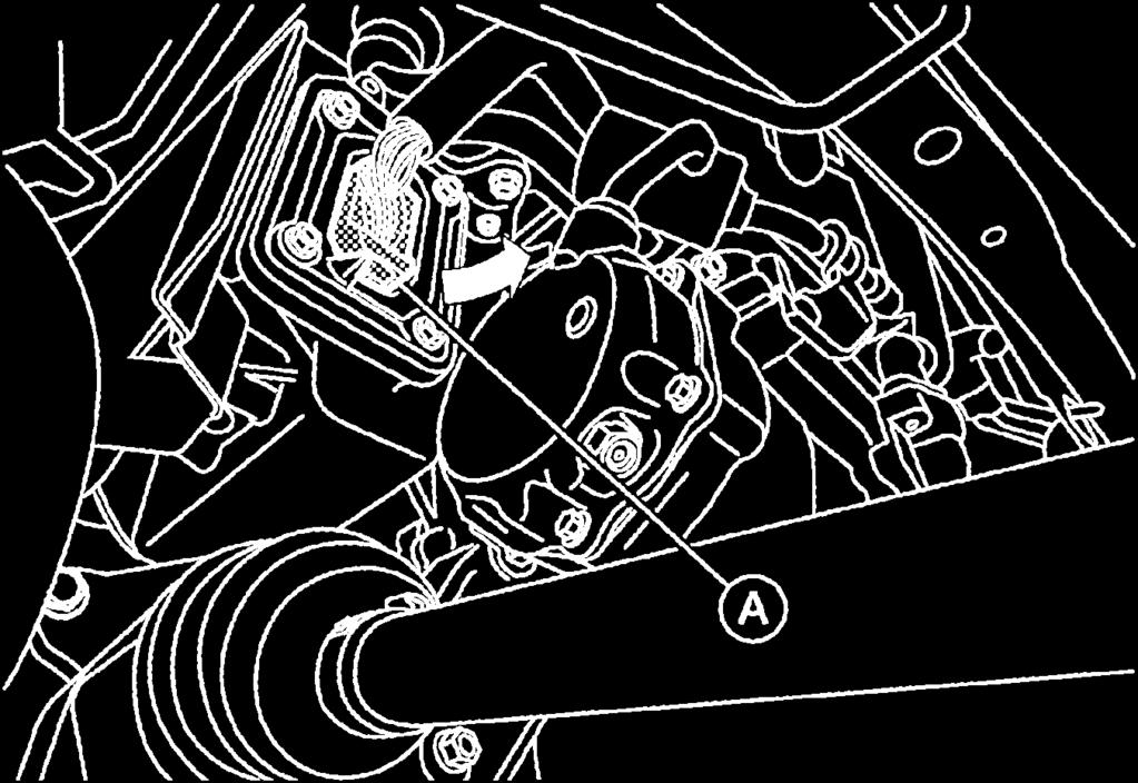
15 29. Remove the charging port s mounting nuts N m (1.0 kg-m, 89 in-lb) 30. Remove the charge connector lock actuator. 31. Pull out the charge ports toward the rear of the vehicle. Mounting nuts. 4 nuts per charging port. Quick charge port Charge connector lock actuator Normal charge port Figure Remove the bus bar cover (use new cover from Parts Information for reassembly) and then remove the bus bar fastening bolt between the PDM and inverter. Bus bar cover: 10.0 N m (1.0 kg-m, 89 in-lb) Bus bar fastener: 13.5 N m (1.4 kg-m, 10 ft-lb) CAUTION: Cover opening of PDM with tape or equivalent to seal out foreign materials. Bus bar cover Bus bar fastening bolt Figure 29 15/25 NTB14-046


16 33. Remove the PDM mounting bolts N m (2.6 kg-m, 18 ft-lb) PDM bolts PDM bolts Figure Insert guide pins (pins J found in kit J-51032) into the PDM mounting bolt holes shown in Figure 31 and in Figure 41 on page 21. NOTE: Always install and remove the guide pins by hand. Guide pin Guide pins Figure Place a fender cover, or equivalent, over the lower edge of the windshield to protect the glass from damage. 16/25 NTB14-046
 onto the")


17 36. Install the PDM Lifting Brackets (J found in kit J-51032) onto the PDM (Figure 32). Assembly torque: 25 N m (2.6 kg-m, 18 ft-lb) Lifting Bracket Lifting Bracket Figure Install the shackle onto the left and right PDM Lifting Brackets, and then install the engine crane. NOTE: Because of the engine hood rod, remove the PDM from the vehicle left side as shown in Figure 33. Figure 33 17/25 NTB14-046
 while raising the engine crane.")
 has not moved.")
18 38. Separate the PDM from the Traction Motor Inverter. Because the bus bar gasket is difficult to remove, gently rock the PDM while raising the engine crane. When lifting with the engine crane, the PDM tilts. Therefore hold the bus bar side (vehicle left side) while raising the engine crane. When the PDM has been raised to at or above the height of the bus bar, move the engine crane, avoiding the bus bar, and pull to remove from the locating pins. CAUTION: Be careful that the engine crane does not contact the hood. Confirm that the windshield protection (fender cover) has not moved. When removing, be careful that the PDM does not contact the windshield glass. When moving, be careful that the PDM does not contact the high-voltage bus bar. 39. Prepare the work bench, and lower the PDM onto blocks of wood or similar material. PDM Wood blocks Figure Cover the high-voltage bus bar opening shown in the shaded area in Figure 35 with tape to prevent intrusion of any foreign material, dust or moisture. Cover with tape Figure 35 18/25 NTB14-046


19 Remove the Traction Motor Inverter Traction Motor Inverter connector cover 1. Remove the Traction Motor Inverter connector cover. NOTE: Figure 36 shown with PDM in place for reference only. Figure Disconnect the Traction Motor Inverter connector. Traction Motor Inverter connector Figure 37 19/25 NTB14-046
. 10 N m (1.")


20 3. Remove the 3-phase bus bar cover (use new gasket from Parts Information for reassembly). 10 N m (1.0 kg-m, 7 ft-lb) IMPORTANT: When reassembling the 3-phase bus bar cover, the raised lip of the metal gasket MUST face the Inverter. Bus bar cover NOTE: Figure 38 shown with PDM in place for reference only. Figure Remove the 3-phase bus bar mounting bolts N m (1.4 kg-m, 10 ft-lb) When removing the 3-phase bus bar mounting bolts, never drop the bolts into the traction motor. After the 3-phase bus bar mounting bolts are removed: Close the opening using tape or an equivalent to prevent dirt, dust, or foreign material from entering the Traction Motor. Figure 39 Bus bar mounting bolts When leaving workspace for a long time, install the 3-phase bus bar cover. 5. Remove the Traction Motor Inverter mounting bolts. 25 N m (2.6 kg-m, 18 ft-lb) Figure 40 20/25 NTB14-046

 in vehicle front. Guide pins Figure 41 8.")

21 6. Install the guide pins (J-51050) into the Traction Motor Inverter mounting bolt holes (2 holes located in vehicle rear). NOTE: Always install and remove the guide pins by hand. 7. Remove the Traction Motor Inverter by hand. Remove the Traction Motor Inverter in the vertical direction. Do not damage the 3-phase bus bar. Do not damage the bolt hole threaded portion located on the Traction Motor side, where the guide pins are installed. NOTE: Dowel pins are located around the Traction Motor Inverter mounting bolt holes (two locations) in vehicle front. Guide pins Figure Remove the seal from the opening of Traction Motor side 3-phase bus bar (use new seal from Parts Information for reassembly). Traction Motor to Inverter seal. Cover with tape until ready to reassemble. 9. Cover the 3-phase bus bar opening on the Traction Motor with tape to prevent foreign material from entering the drive motor. CAUTION: Always protect the bus bar section. If the bus bar is touched or dirty, clean it using isopropanol. Figure 42 WARNING: To prevent electric shock hazards, be sure to put on insulating protective gear before reconnecting the high voltage system to the vehicle battery. 21/25 NTB14-046
22 10. Install the new Traction Motor Inverter from the Parts Information table and the preexisting PDM in the reverse order. When installing the Traction Motor Inverter and PDM, always use the guide pins J Remove the guide pins when finished. CAUTION: Be careful not to damage the 3-phase bus bar. Check that the dowel pins are inserted to their end positions completely. When attaching the seal to the opening of Traction Motor side 3-phase bus bar, be sure to install the convex portion of the seal to the installation groove completely. Never reuse the seal for the opening of Traction Motor side 3-phase bus bar. Never reuse the gasket for the 3-phase bus bar cover. Inspection after Installation After installing the Traction Motor Inverter and PDM, measure resistance between: Traction Motor Inverter and other high voltage system. Traction Motor Inverter and body. Resistance standard is less than 0.1 Ω NOTE: If result deviates from standard values, check that no paint, oil, dirt, or other substance is adhering to bolts or conductive mounting parts. If any such substance is adhering, clean the surrounding area and remove the substance. Refilling the Cooling System 1. Check that all hose clamps have been firmly tightened. 2. Refill reservoir tank to MAX level line with engine coolant. 3. Install reservoir tank cap. 4. Set the vehicle to READY and operate the electric water pump. 5. If reservoir tank fluid level drops, set the vehicle in READY OFF state and fill the coolant to the MAX line of the reservoir tank. 6. Repeat from step 4 and 5 until the reservoir tank fluid level stops dropping. 7. Operate the electrically-controlled water pump for approximately 10 minutes with the vehicle set in READY state, and check that the reservoir tank fluid level does not drop. 8. If reservoir tank fluid level drops, repeat steps 4 to 7. 22/25 NTB14-046


23 Writing of the Traction Motor Resolver Offset with CONSULT Figure Turn ignition switch ON. NOTE: EV system warning lamp will come on. 2. Select Work Support in MOTOR CONTROL. 3. Select RESOLVER WRITE. 4. Enter the traction motor resolver offset (Figure 43). NOTE: Because the traction motor resolver offset stamp is located on the lower side of the traction motor, it is necessary to remove the undercover in order to check it. 5. Touch WRITE. 6. Is Writing is complete displayed? YES: Proceed to step 7. NO: Perform steps 2-6 again. 7. Turn the ignition switch OFF. 8. Turn the ignition ON and wait 2 seconds or more. 9. Verify that the EV system warning lamp is OFF. 10. Select Work Support in MOTOR CONTROL. 11. Select RESOLVER WRITE. 12. Confirm the value has changed according to the correction value input. 13. Perform Self Diagnostic Results in MOTOR CONTROL. 14. Erase the DTC P325C. 15. Turn ignition OFF. Disconnect VI and turn OFF CONSULT PC. 23/25 NTB14-046
24 Reset Customer Settings 1. Reset the clock in the combination meter. 2. Reset the radio settings. 3. If equipped, check/reset the clock in the navigation system. 4. If equipped, reset the customer preferred settings for the Automatic Air Conditioning System. If needed, refer to System Settings in the HAC section of the ESM. 5. Inform the customer: If equipped, some memory settings in the navigation system may need to be reset. If equipped, some charging and climate control timers may need to be reset. 6. Reinitialize and check the Anti-Pinch Function for all Auto-UP power windows: Reinitialize: a. Turn the ignition ON. b. Operate the power window switch to fully open the window (glass all the way down). c. Hold the window switch UP until the glass stops at the fully closed position, and then continue holding the switch UP for 2 seconds or more. d. Check that AUTO-UP function operates normally. Check Anti-Pinch Function a. Fully open the door window (glass all the way down). b. Hold a piece of wood near the fully closed position. c. Close the door window glass using the AUTO-UP switch. Allow the window glass to hit the wood. d. Check the following conditions: Check that the glass lowers for approximately 150 mm (5.9 in), without pinching the wood, and stops. Check that the glass does not rise when operating the power window main switch, while the widow is lowering after hitting the wood. CAUTION: Do not check anti-pinch function with hands or other body parts because they may be pinched. 24/25 NTB14-046
25 PARTS INFORMATION DESCRIPTION PART # QUANTITY INVERTER COMP-POWER HEAD 291A0-3NF1A 1 SEAL - O RING 290Y6-3NF0B 1 (Inverter to Traction Motor) GASKET 290H9-3NF1C 1 (Inverter to Traction Motor Bus Bar Cover seal) COVER-SUB, POWER CONVERTER (PDM to Inverter Bus Bar Cover seal) 292A2-3NF1A 1 CLAIMS INFORMATION Submit a CM line claim using the following claims coding: CM I.D.: PC281 CAMPAIGN ID DESCRIPTION OP CODE FRT PC281 Replace Traction Motor Inverter PC hrs. 25/25 NTB14-046
VOLUNTARY RECALL CAMPAIGN MURANO ALTERNATOR
 2003 Nissan Murano 3.5L Eng SE VOLUNTARY RECALL CAMPAIGN 2003-05 MURANO ALTERNATOR SERVICE CAMPAIGN BULLETIN Reference Number(s): NTB05-059, Date of Issue: July 28, 2005 NISSAN: 2003-05 Murano CAMPAIGN
VOLUNTARY SAFETY RECALL CAMPAIGN ARMADA AND TITAN FRONTIER, PATHFINDER AND XTERRA ECM RELAY
 `Reference: NTB10-137b December 22, 2010 Date: VOLUNTARY SAFETY RECALL CAMPAIGN 2004 2006 ARMADA AND TITAN 2005 2006 FRONTIER, PATHFINDER AND XTERRA ECM RELAY This bulletin has been amended. The SERVICE
VOLUNTARY RECALL CAMPAIGN PASSENGER AIR BAG OCCUPANT CLASSIFICATION SYSTEM (OCS)
") Reference: NTB08-095c December 4, 2008 Date: VOLUNTARY RECALL CAMPAIGN 2007 2009 PASSENGER AIR BAG OCCUPANT CLASSIFICATION SYSTEM (OCS) This bulletin has been amended. Instruction for the AC adapter has
Reference: NTB08-095c December 4, 2008 Date: VOLUNTARY RECALL CAMPAIGN 2007 2009 PASSENGER AIR BAG OCCUPANT CLASSIFICATION SYSTEM (OCS) This bulletin has been amended. Instruction for the AC adapter has
VOLUNTARY SAFETY RECALL CAMPAIGN QUEST FUEL PUMP CONTROL MODULE
 Reference: NTB12-022a April 12, 2012 Date: VOLUNTARY SAFETY RECALL CAMPAIGN 2011-2012 QUEST FUEL PUMP CONTROL MODULE This bulletin has been amended. The NHTSA # and OWNER S LETTER have been added. Please
VOLUNTARY RECALL CAMPAIGN ELECTRONIC CONTROL MODULE (ECM) CASE HOLDER FOAM
 CASE HOLDER FOAM") Reference: NTB03-112 December 10, 2003 VOLUNTARY RECALL CAMPAIGN ELECTRONIC CONTROL MODULE (ECM) CASE HOLDER FOAM Date: CAMPAIGN I.D. # / NHTSA #: P3163 / 03V-477 APPLIED VEHICLES: 2000-2003 Sentra (B15)
Reference: NTB03-112 December 10, 2003 VOLUNTARY RECALL CAMPAIGN ELECTRONIC CONTROL MODULE (ECM) CASE HOLDER FOAM Date: CAMPAIGN I.D. # / NHTSA #: P3163 / 03V-477 APPLIED VEHICLES: 2000-2003 Sentra (B15)
VOLUNTARY SERVICE CAMPAIGN ALTIMA; HALOGEN HEADLAMP GROUND PLATE KIT
 Reference: NTB05-057b March 14, 2008 Date: VOLUNTARY SERVICE CAMPAIGN 2002 2003 ALTIMA; HALOGEN HEADLAMP GROUND PLATE KIT This bulletin amends NTB05-057a. The IMPORTANT statements on page 3 and page 20
VOLUNTARY RECALL CAMPAIGN PASSENGER AIR BAG OCCUPANT CLASSIFICATION SYSTEM (OCS)
") Reference: ITB08-045d December 4, 2008 Date: VOLUNTARY RECALL CAMPAIGN 2007 2008 PASSENGER AIR BAG OCCUPANT CLASSIFICATION SYSTEM (OCS) This bulletin has been amended. Instruction for the AC adapter has
Reference: ITB08-045d December 4, 2008 Date: VOLUNTARY RECALL CAMPAIGN 2007 2008 PASSENGER AIR BAG OCCUPANT CLASSIFICATION SYSTEM (OCS) This bulletin has been amended. Instruction for the AC adapter has
VOLUNTARY RECALL CAMPAIGN FUEL PUMP SCREEN
 Reference: NTB03-077a August 21, 2003 VOLUNTARY RECALL CAMPAIGN FUEL PUMP SCREEN Date: This bulletin amends NTB03-077. This version updates the Service Procedure. Please discard all paper copies of the
VOLUNTARY RECALL CAMPAIGN FUEL HOSES
 Reference: ITB06-006b April 4, 2006 Date: VOLUNTARY RECALL CAMPAIGN FUEL HOSES This bulletin has been amended. The Re-Assembly procedure for FX and G35 has been expanded. Please discard all previous versions
VOLUNTARY SERVICE CAMPAIGN G35 SEDAN AND COUPE SEAT MOUNTED SIDE AIR BAG HARNESS CONNECTOR
 Reference: ITB10-034b June 22, 2012 Date: VOLUNTARY SERVICE CAMPAIGN 2003 2004 G35 SEDAN AND COUPE SEAT MOUNTED SIDE AIR BAG HARNESS CONNECTOR This bulletin has been amended. Changes have been made throughout
VOLUNTARY RECALL CAMPAIGN SKYVIEW ROOF GLASS
 Reference: NTB04-100a November 5, 2004 VOLUNTARY RECALL CAMPAIGN SKYVIEW ROOF GLASS Date: IMPORTANT: THIS BULLETIN HAS BEEN REVISED. Figure 10 (page 7) was revised to include a rubber seal on the glass.
VOLUNTARY SAFETY RECALL CAMPAIGN 2006 AND 2008 FRONTIER, XTERRA, PATHFINDER FUEL GAUGE INACCURACY
 Reference: NTB10-031 March 18, 2010 Date: VOLUNTARY SAFETY RECALL CAMPAIGN 2006 AND 2008 FRONTIER, XTERRA, PATHFINDER FUEL GAUGE INACCURACY CAMPAIGN ID #: PC042 NHTSA #: 10V-075 APPLIED VEHICLES: 2006
ARTICLE BEGINNING SERVICE PRECAUTIONS
 Page 1 of 96 ARTICLE BEGINNING SERVICE PRECAUTIONS WARNING: WARNING: CAUTION: When performing any inspection or service procedure on this vehicle, ensure following service precautions are followed to prevent
VOLUNTARY SERVICE CAMPAIGN 2006 M35 / M45; RADIATOR FAN CONTROL MODULE
 Reference: ITB08-036 August 7, 2008 Date: VOLUNTARY SERVICE CAMPAIGN 2006 M35 / M45; RADIATOR FAN CONTROL MODULE CAMPAIGN ID #: P8227 APPLIED VEHICLE: 2006 M35 / M45 (Y50) Refer to Infiniti Net to confirm
2004 NISSAN TITAN; UPPER INTERIOR OCCUPANT PROTECTION VOLUNTARY SAFETY RECALL CAMPAIGN
 Reference: NTB04-086 September 22, 2004 Date: 2004 NISSAN TITAN; UPPER INTERIOR OCCUPANT PROTECTION VOLUNTARY SAFETY RECALL CAMPAIGN CAMPAIGN I.D. # / NHTSA #: R0406 / 04V-345 APPLIED VEHICLE: 2004 Titan
ALTIMA SEDAN, COUPE, AND HYBRID; ENGINE NO CRANK / NO START
 Classification: Reference: Date: EL10-030 NTB10-139 November 23, 2010 ALTIMA SEDAN, COUPE, AND HYBRID; ENGINE NO CRANK / NO START APPLIED VEHICLES: 2007 2010 Altima Sedan (L32) with CVT only 2008 2010
TECHNICAL INSTRUCTIONS FOR SAFETY RECALL E0G SUB HARNESS (FILTER) INSTALLATION
 INSTALLATION") TECHNICAL INSTRUCTIONS FOR SAFETY RECALL E0G SUB HARNESS (FILTER) INSTALLATION 2003 2004 MODEL YEAR AVALON COLUMN MOUNTED SHIFT LEVER (FRONT BENCH SEAT) All dealership associates involved in the recall
TECHNICAL INSTRUCTIONS FOR SAFETY RECALL E0G SUB HARNESS (FILTER) INSTALLATION 2003 2004 MODEL YEAR AVALON COLUMN MOUNTED SHIFT LEVER (FRONT BENCH SEAT) All dealership associates involved in the recall
2007 MAXIMA; MIL 'ON' W/DTC P0840 OR P0845
 Classification: Reference: Date: AT08-001 NTB08-042 April 3, 2008 2007 MAXIMA; MIL 'ON' W/DTC P0840 OR P0845 APPLIED VEHICLE: 2007 Maxima (A34) IF YOU CONFIRM The MIL is ON with one of the following DTC
ILLUSTRATION ILLUSTRATION
 ILLUSTRATION ILLUSTRATION REMOVAL 1. DISABLE BRAKE CONTROL (a) Wait at least 2 minutes after the power switch off. When the brake pedal is depressed or the door courtesy switch is turned on even if the
2010 Toyota Prius Repair Manual
 REMOVAL 1. DISABLE BRAKE CONTROL (a) Wait at least 2 minutes after the power switch off. NOTICE: When the brake pedal is depressed or the door courtesy switch is turned on even if the power switch is off,
MAXIMA DRIVER'S POWER SEAT WILL NOT MOVE FORWARD OR BACKWARD
 Classification: Reference: Date: EL01-030d NTB02-001d December 21, 2004 2000-2003 MAXIMA DRIVER'S POWER SEAT WILL NOT MOVE FORWARD OR BACKWARD This bulletin amends NTB02-001. The Applied Vehicles have
Item C& D Not Applicable C
 GENUINE PARTS INSTALLATION INSTRUCTIONS DESCRIPTION: APPLICATION: PART NUMBER(S) REQUIRED FOR INSTALLATION: KIT CONTENTS: LED Fog Lamp Upgrade Rogue Sport 999F1 V4001 A B Item C& D Not Applicable C D Do
EX35, G35, G37; STEERING WHEEL SWITCH FINISHER SERVICE PARTS
 Classification: Reference: Date: ST12-006 ITB12-050 August 14, 2012 EX35, G35, G37; STEERING WHEEL SWITCH FINISHER SERVICE PARTS APPLIED VEHICLES: 2007-2008 G35 Sedan (V36) 2009-2012 G37 Sedan (V36) 2008-2013
NISSAN BULLETIN 2015 Murano ABS Actuator Voluntary Safety Recall Campaign
 NISSAN BULLETIN 2015 Murano ABS Actuator Voluntary Safety Recall Campaign Attention: Dealer Principal, Sales, Service & Parts Managers Reference: PC375 Date: June 5, 2015 A STOP SALE CONDITION IS IN EFFECT.
TECHNICAL INSTRUCTIONS FOR LIMITED SERVICE CAMPAIGN (LSC) A0N HV WATER PUMP REPLACEMENT MODEL YEAR PRIUS
 A0N HV WATER PUMP REPLACEMENT MODEL YEAR PRIUS") TECHNICAL INSTRUCTIONS FOR LIMITED SERVICE CAMPAIGN (LSC) A0N HV WATER PUMP REPLACEMENT 2004 2007 MODEL YEAR PRIUS I. OPERATION FLOWCHART II. IDENTIFICATION OF AFFECTED VEHICLES A. AFFECTED VIN RANGE Model
TECHNICAL INSTRUCTIONS FOR LIMITED SERVICE CAMPAIGN (LSC) A0N HV WATER PUMP REPLACEMENT 2004 2007 MODEL YEAR PRIUS I. OPERATION FLOWCHART II. IDENTIFICATION OF AFFECTED VEHICLES A. AFFECTED VIN RANGE Model
MAXIMA DRIVER'S POWER SEAT WILL NOT MOVE FORWARD OR BACKWARD TECHNICAL SERVICE BULLETIN
 Page 1 of 11 2000-2003 MAXIMA DRIVER'S POWER SEAT WILL NOT MOVE FORWARD OR BACKWARD TECHNICAL SERVICE BULLETIN Reference Number(s): NTB02-001d, Date of Issue: December 21, 2004 NISSAN: 2000-2003 Maxima
INSTALLATION INSTRUCTIONS
 INSTALLATION INSTRUCTIONS Accessory Application Publications No. BII 39552 ENGINE BLOCK 2009 RDX Issue Date P/N 08T44-SJA-200 MAY 2008 PARTS LIST NOTE: NOTE: Installation of the engine block heater requires
FX35; DTC P0300 AND IGNITION COILS BLISTERED
 Classification: Reference: Date: EC11-007 ITB11-017 March 1, 2011 2003 2008 FX35; DTC P0300 AND IGNITION COILS BLISTERED APPLIED VEHICLES: 2003 2008 FX35 (S50) IF YOU CONFIRM Cylinder Misfire DTC (P0300
ALTIMA SEDAN; SLIGHT DRIVER'S POWER SEAT MOVEMENT SIDE-TO-SIDE
 Classification: Reference: Date: BT08-025b NTB08-089b November 12, 2009 2007-2010 ALTIMA SEDAN; SLIGHT DRIVER'S POWER SEAT MOVEMENT SIDE-TO-SIDE The ACTION statement, Applied Vehicles/VINs/Dates/, Parts
CustomerServicesDivision Toyota Motor Sales, U.S.A., Inc South Western Avenue P.O. Box 2991 Torrance, CA
 CustomerServicesDivision Toyota Motor Sales, U.S.A., Inc. 19001 South Western Avenue P.O. Box 2991 Torrance, CA 90509 2991 TO: ALL TOYOTA DEALER PRINCIPALS, SERVICE MANAGERS, PARTS MANAGERS SUBJECT: SPECIAL
TECHNICAL INSTRUCTIONS FOR SAFETY RECALL ALE VALVE SPRING AND LASH ADJUSTER REPLACEMENT GS 350: IS 350:
 TECHNICAL INSTRUCTIONS FOR SAFETY RECALL ALE VALVE SPRING AND LASH ADJUSTER REPLACEMENT GS 350: 2007 2008 IS 350: 2006 2008 I. OPERATION FLOWCHART Verify Vehicle Eligibility 1. Check the VIN range. 2.
A. VEHICLE INSPECTION PROCEDURE
 MAZDA3 AND MAZDA5 POWER STEERING VOLUNTARY SAFETY RECALL ATTACHMENT IV MAZDA3 AND MAZDA5 POWER STEERING VOLUNTARY SAFETY RECALL A. VEHICLE INSPECTION PROCEDURE 1. Verify that the vehicle is within the
Z; BOSE AUDIO AMPLIFIER CUSTOMER SATISFACTION INITIATIVE
 Classification: Reference: Date: EL03-026 NTB03-086 October 1, 2003 2003 350Z; BOSE AUDIO AMPLIFIER CUSTOMER SATISFACTION INITIATIVE IMPORTANT This bulletin supercedes bulletin NTB02-111a Refer to this
2001 MAXIMA ALARM SOUNDS AFTER 30 MINUTES AND/OR TRUNK LAMP INOPERATIVE
 Classification: Reference: Date: EL0-00 NTB0-009 February 9, 00 00 MAXIMA ALARM SOUNDS AFTER 30 MINUTES AND/OR TRUNK LAMP INOPERATIVE APPLIED VEHICLES: 00 Maxima (A33) APPLIED VINS: Vehicles built before:
LANCER FOG LAMP KIT MZ380479EX (for RHD) INSTALLATION AND HANDLING INSTRUCTIONS
 INSTALLATION AND HANDLING INSTRUCTIONS") LANCER FOG LAMP KIT MZ380479EX (for RHD) INSTALLATION AND HANDLING INSTRUCTIONS Fog lamp Thank you for purchasing the Mitsubishi Genuine Accessory. To install and use the product correctly with proper
LANCER FOG LAMP KIT MZ380479EX (for RHD) INSTALLATION AND HANDLING INSTRUCTIONS Fog lamp Thank you for purchasing the Mitsubishi Genuine Accessory. To install and use the product correctly with proper
SUNROOF RAIL ASSEMBLY REPAIR
 Classification: Reference: Date: BT99-049 NTB00-001 December 15, 1999 SUNROOF RAIL ASSEMBLY REPAIR APPLIED VEHICLES: 1995-97 Maxima (A32) 1996-99 Pathfinder (R50) SERVICE INFORMATION If an applied vehicle
INSTALLATION INSTRUCTIONS
 INSTALLATION INSTRUCTIONS Accessory S Application 2011 ODYSSEY Publications No. AII 43917 Issue Date SEP 2010 PARTS LIST Fog Light Kit P/N 08V31-TK8-100 Left fog light 20A Fuse Relay Right fog light Light
PATHFINDER, QUEST, MURANO, MAXIMA, ALTIMA V6 CVT JUDDER AND DTC P17F0 OR P17F1 STORED
 Classification: Reference: Date: APPLIED VEHICLE: AT15-005b NTB15-015b September 10, 2015 PATHFINDER, QUEST, MURANO, MAXIMA, ALTIMA V6 CVT JUDDER AND DTC P17F0 OR P17F1 STORED This bulletin has been amended
INSTALLATION INSTRUCTIONS
 INSTALLATION INSTRUCTIONS Accessory ENGINE BLOCK P/N 08T44-SWA-1A0 Application 2012 CIVIC 4-DOOR Si Publications No. AII 45627 Issue Date APRIL 2011 PARTS LIST Engine block heater Aluminum washer Heater
Steps 3 through 9 in this procedure describe making and using a cooling system bleed tool.
 Cooling System Bleed Procedure Steps 3 through 9 in this procedure describe making and using a cooling system bleed tool. However, you can use a commercially available funnel-type coolant refill bleed
GENUINE PARTS INSTALLATION INSTRUCTIONS
 GENUINE PARTS INSTALLATION INSTRUCTIONS DESCRIPTION: APPLICATION: PART NUMBERS: Sports Horn Murano / Murano Cross Cabriolet (2011) Sports Horn (B5610 1SXOA) KIT CONTENTS: Item QTY. Description Part Number
QX4; DRIVER'S SEAT (WITH ADP ONLY) WON'T MOVE FORWARD OR BACKWARD
 WON'T MOVE FORWARD OR BACKWARD") Classification: Reference: Date BT00-030a ITB00-065a December 21, 2004 2001 2003 QX4; DRIVER'S SEAT (WITH ADP ONLY) WON'T MOVE FORWARD OR BACKWARD This bulletin amends ITB00-065. This version amends the
Classification: Reference: Date BT00-030a ITB00-065a December 21, 2004 2001 2003 QX4; DRIVER'S SEAT (WITH ADP ONLY) WON'T MOVE FORWARD OR BACKWARD This bulletin amends ITB00-065. This version amends the
INSTALLATION INSTRUCTIONS
 INSTALLATION INSTRUCTIONS Accessory Application Publications No. ENGINE BLOCK P/N 08T44-SJA-200 2008 FIT AII 37494 Issue Date JUL 2007 PARTS LIST Engine block heater Aluminum washer Heater harness Protective
INSTALLATION INSTRUCTIONS
 Accessory Application Publication No. INSTALLATION INSTRUCTIONS LED HEADLIGHT P/N 08V71-HL4-A00 SXS1000M3/M3P/M5P Honda Dealer: Please give a copy of these instructions to your customer. MII 15262 Issue
Technical Bulletin. Reference: NTB15-087a CVT WITH 4 CYLINDER ENGINE VALVE BODY REPLACEMENT WITH CONFIRMED DTC
 2014 Nissan-Datsun Altima Sedan L4-2.5L (QR25DE) Vehicle > ALL Diagnostic Trouble Codes ( DTC ) > Technical Service Bulletins CVT WITH 4 CYLINDER ENGINE VALVE BODY REPLACEMENT WITH CONFIRMED DTC Technical
July Models. Subject
 Dealer Service Instructions for: July 2001 Safety Recall No. 970 Models 1994-1996 (BR) Dodge Ram Pickup Trucks NOTE: This recall applies only to the above vehicles equipped with a 5.9L Cummins turbo diesel
INSTALLATION INSTRUCTIONS
 INSTALLATION INSTRUCTIONS Accessory Application Publications No. AII 24642 BODY SIDE CLADDING 2003 CR-V P/N 08P21-S9A-100 Issue Date OCT 2002 PARTS LIST Right rear bumper piece Right front fender piece
TECHNICAL INSTRUCTIONS
 TECHNICAL INSTRUCTIONS RAV4 SPIRAL CABLE SUB-ASSEMBLY REPLACEMENT 1. OPERATION FLOW CHART --------------------------------- 3 2. IDENTIFICATION OF AFFECTED VEHICLES ---------- 4 3. PREPARATION --------------------------------------------------
TITAN AND ARMADA DRIVER SIDE AIR MIX DOOR MOTOR REPLACEMENT
 Classification: Reference: Date: HA11-004 NTB11-048 May 5, 2011 2004 2011 TITAN AND ARMADA DRIVER SIDE AIR MIX DOOR MOTOR REPLACEMENT APPLIED VEHICLE: 2004 2011 Titan (A60) 2004 2011 Armada (TA60) IF YOU
TECHNICAL INSTRUCTIONS FOR SPECIAL SERVICE CAMPAIGN 40F
 TECHNICAL INSTRUCTIONS FOR SPECIAL SERVICE CAMPAIGN 40F 2002 THROUGH EARLY 2004 MODEL YEAR NORTH AMERICAN PRODUCED (NAP) TOYOTA CAMRY CURTAIN SIDE AIRBAG Page 1 of 26 I. OPERATION FLOW CHART Verify Vehicle
TOYOTA TUNDRA TVIP V4 REMOTE ENGINE STARTER (RES)
") Preparation Part Number: 08586-OC910 Conflicts Do not install into vehicles without RKE systems. Recommended Sequence of Application Item # Accessory 1 TVIP/RES Any TVIP or RES system 2 XM Radio NOTE:
Preparation Part Number: 08586-OC910 Conflicts Do not install into vehicles without RKE systems. Recommended Sequence of Application Item # Accessory 1 TVIP/RES Any TVIP or RES system 2 XM Radio NOTE:
INSTALLATION INSTRUCTIONS
 INSTALLATION INSTRUCTIONS Accessory Application Publications No. S P/N 08V31-SCV-100B 2008 ELEMENT (SC) AII 36532 Issue Date MAY 2007 PARTS LIST Relay bracket Right fog light Relay Left fog light Fuse
ALTIMA; POOR HEATER PERFORMANCE
 Classification: Reference: Date: HA02-002b NTB02-047b September 9, 2003 2002 2003 ALTIMA; POOR HEATER PERFORMANCE This bulletin amends NTB02-047a. This version updates the Service Procedure. Please discard
LEXUS LC/LCh CARBON FIBER LOWER GRILLE Preparation
 Preparation Part Number: PT478-11175-05 Kit Contents Item # Quantity Reqd. Description 1 1 Carbon Fiber Lower Grille Insert 2 3 Hardware Bag Contents Item # Quantity Reqd. Description 1 2 3 Additional
GENUINE PARTS INSTALLATION INSTRUCTIONS
 GENUINE PARTS INSTALLATION INSTRUCTIONS 1. DESCRIPTION: 2. APPLICATION: 3. PART NUMBER(S) REQUIRED FOR INSTALLATION: 4. KIT CONTENTS: Item Qty. Fog Lamp Kit Titan MY16 999F1 W4000 Fog Lamp Kit Part Description
Service Bulletin
 Service Bulletin 08-043 Applies To: 2003 Accord 4-door ALL October 15, 2008 Safety Recall: Windshield Wiper Motor Does Not Work (Supersedes 08-043, dated July 17, 2008, to update the information marked
ALLDATA Online Toyota Prius L4-1.8L (2ZR-FXE) Hybrid - Hybrid Control Sy... Hybrid Control System
 Hybrid - Hybrid Control Sy... Hybrid Control System") Page 1 of 6 2010 Toyota Prius L4-1.8L (2ZR-FXE) Hybrid Vehicle Level Hybrid Drive Systems Service Precautions Hybrid Control System Hybrid Control System HYBRID / BATTERY CONTROL: HYBRID CONTROL SYSTEM:
Page 1 of 6 2010 Toyota Prius L4-1.8L (2ZR-FXE) Hybrid Vehicle Level Hybrid Drive Systems Service Precautions Hybrid Control System Hybrid Control System HYBRID / BATTERY CONTROL: HYBRID CONTROL SYSTEM:
INSTALLATION INSTRUCTIONS
 Accessory Application Publication No. INSTALLATION INSTRUCTIONS WINCH MOUNT P/N 08L73-HL4-F01 After 16 SXS1000M3/M3P/M3LE SXS1000M5P/M5D/M5LE MII 16083 Issue Date February 2017 PARTS LIST No. Description
Wiper and Washer Systems: All Technical Service Bulletins Service Procedure 1. Turn ignition switch to the "Accessory" position.
 1998 Buick Century V6-3100 3.1L VIN M SFI Page 1 Wiper and Washer Systems: All Technical Service Bulletins Service Procedure 1. Turn ignition switch to the "Accessory" position. 2. Set wiper switch to
FUEL SYSTEM PRECAUTION FU 1
 2GR-FE EL EL SYSTEM EL SYSTEM PRECAUTION 1 1. EXPRESSIONS OF IGNITION SWITCH (a) The type of the ignition switch used on this model differs according to the specifications of the vehicle. The expressions
MURANO; AUTOMATIC BACK DOOR DOES NOT OPERATE AND RELATED DTCS
 Classification: Reference: Date: BT15-020b NTB15-073b March 22, 2016 2015-2016 MURANO; AUTOMATIC BACK DOOR DOES NOT OPERATE AND RELATED DTCS This bulletin has been amended. Changes have been made to all
2012 Kia Soul L4 2.0L
 2012 Kia Soul L4 2.0L Vehicle» Engine, Cooling and Exhaust» Engine» Timing Chain» Service and Repair» Repair Procedures» Part 1 Removal Engine removal is not required for this procedure. CAUTION: Use fender
REMOVAL AND INSTALLATION
 501-12-1 Instrument Panel and Console 501-12-1 REMOVAL AND INSTALLATION Instrument Panel Removal CAUTION: Electronic modules are sensitive to static electrical charges. If exposed to these charges, damage
INSTALLATION INSTRUCTIONS
 INSTALLATION INSTRUCTIONS Accessory TRIM Application 2009 ACCORD 4-DOOR Publications No. AII 40008 Issue Date JULY 2008 PARTS LIST Steering Wheel Trim (Without Navigation) P/N 08Z13-TA0-100 Right steering
TECHNICAL INSTRUCTIONS FOR SAFETY RECALL D0H BRAKE BOOSTER PUMP ASSEMBLY (ACCUMULATOR) CERTAIN 2010 MODEL YEAR PRIUS
 CERTAIN 2010 MODEL YEAR PRIUS") TECHNICAL INSTRUCTIONS FOR SAFETY RECALL D0H BRAKE BOOSTER PUMP ASSEMBLY (ACCUMULATOR) CERTAIN 2010 MODEL YEAR PRIUS Complete D0H Technical Video Supplement I. OPERATION FLOW CHART The flow chart is for
TECHNICAL INSTRUCTIONS FOR SAFETY RECALL D0H BRAKE BOOSTER PUMP ASSEMBLY (ACCUMULATOR) CERTAIN 2010 MODEL YEAR PRIUS Complete D0H Technical Video Supplement I. OPERATION FLOW CHART The flow chart is for
ATTACHMENT II 2007 MAZDASPEED3 NO. 4 ENGINE MOUNT 4607F
 2007 MAZDASPEED3 NO. 4 ENGINE MOUNT 2007 MAZDASPEED3 NO. 4 ENGINE MOUNT A. VEHICLE INSPECTION PROCEDURE 1. Verify that the vehicle is within the following ranges: Year Range (2007) Model (MAZDASPEED3)
Service Bulletin 1988 PRELUDE. RECALL: 1988 Prelude Power Steering Supply Hose
 Service Bulletin Model Applicable To File Under Bulletin No. 1988 PRELUDE See VEHICLES AFFECTED ENGINE 88-014 Issue Date APRIL 20, 1988 RECALL: 1988 Prelude Power Steering Supply Hose PROBLEM When subjected
Service Bulletin
 Service Bulletin 10-082 Applies To: 2007 08 Fit ALL March 11, 2011 Safety Recall: 2007 08 Fit Low Beam Headlights May Not Work (Supersedes 10-082, dated January 28, 2011, to revise the information marked
INSTALLATION INSTRUCTIONS
 INSTALLATION INSTRUCTIONS Accessory REMOTE ENGINE STARTER SYSTEM Application 2010 CIVIC 4-DOOR Publications No. AII 42460 Issue Date AUG 2009 PARTS LIST Remote Engine Starter Unit Kit P/N 08E91-E22-100B
BASIC BRAKE SYSTEM GROUP 35A 35A-1 CONTENTS GENERAL DESCRIPTION... 35A-3 BASIC BRAKE SYSTEM DIAGNOSIS 35A-6
 35A-1 GROUP 35A BASIC BRAKE SYSTEM CONTENTS GENERAL DESCRIPTION......... 35A-3 DIAGNOSIS 35A-6 INTRODUCTION..................... 35A-6 DIAGNOSTIC TROUBLESHOOTING STRATEGY......................... 35A-6
GROUP CONTENTS FRONT BUMPER ASSEMBLY WINDSHIELD WIPER AND WASHER REAR BUMPER ASSEMBLY REAR WIPER AND WASHER...
 5- GROUP 5 CONTENTS FRONT BUMPER ASSEMBLY 5- REMOVAL AND INSTALLATION 5- DISASSEMBLY AND ASSEMBLY 5- REAR BUMPER ASSEMBLY 5-4 REMOVAL AND INSTALLATION 5-4 DISASSEMBLY AND ASSEMBLY 5-4 UNDER FLOOR SPARE
Technical Service Bulletin
 Technical Service Bulletin SUBJECT: GROUP DATE NUMBER CAMPAIGN 17-01-045 JUNE, 2017 MODEL SONATA HYBRID (LF HEV) HYBRID STARTER GENERATOR (HSG) INSPECTION / REPLACEMENT (Service Campaign T2E) IMPORTANT
 INSTALLATION INSTRUCTIONS Accessory Application 2010 CR-V Publications No. AII 42592 Issue Date AUG 2009 PARTS LIST Bass Works Attachment kit (sold separately) P/N 08B54-SWA-100 Bass system harness 4 Washer-bolts,
Product Campaign Bulletin
 Nissan Ireland Cedar House Park West Business Park Nangor Road, Dublin 12 Product Campaign Bulletin REFERENCE: MODEL: PCB-NES-12-052 J10 & J10+2 Qashqai SUBJECT: PCB J10 - PG2B9 and PS2B7- Steering wheel
Service Bulletin. Safety Recall: Fit Low Beam Headlights May Not Work
 Service Bulletin 10-082 Applies To: 2007 08 Fit ALL January 28, 2011 Safety Recall: 2007 08 Fit Low Beam Headlights May Not Work (Supersedes 10-082, dated January 7, 2011, to revise the information marked
INSTALLATION INSTRUCTIONS
 INSTALLATION INSTRUCTIONS Accessory Application Publications No. P/N 08V31-SVA-110 2007 CIVIC 2-DOOR All33536-34848 Issue Date FEB 2007 PARTS LIST 11 Wire ties Right fog light Clip Left fog light 4 Stepped
ELECTRIC VEHICLE DISMANTLING MANUAL
 RAV4 EV Electric Vehicle ELECTRIC VEHICLE DISMANTLING MANUAL QEA38 Series Foreword This guide was developed to educate and assist dismantlers in the safe handling of Toyota RAV4 EV electric vehicles. RAV4
INSTALLATION INSTRUCTIONS
 INSTALLATION INSTRUCTIONS Accessory REMOTE CONTROL Application 2012 ODYSSEY (EXCEPT LX) Publications No. AII 46745 Issue Date SEP 2011 PARTS LIST Remote Control Engine Starter Unit Kit P/N 08E91-E22-101A
2014 Subaru of America, Inc. All rights reserved. SERVICE BULLETIN. Service Procedure to Address a Wind Rushing Sound from the Front Door Sash Area
 ATTENTION: GENERAL MANAGER q PARTS MANAGER q CLAIMS PERSONNEL q SERVICE MANAGER q IMPORTANT - All Service Personnel Should Read and Initial in the boxes provided, right. 2014 Subaru of America, Inc. All
GENUINE PARTS INSTALLATION INSTRUCTIONS
 1. DESCRIPTION: Portable Navigation 2. APPLICATION: Frontier (2005-2008) Xterra (2005-2008) All grades (2005-2007) Base or S-grade only (2008) 3. PART NUMBER: PND main kit (999Q5 KU000) PND Housing (999Q5
Technical Service Bulletin
 Technical Service Bulletin GROUP NUMBER RECALL 17-01-021 DATE MODEL(S) MARCH 2017 See Below SUBJECT: This TSB supersedes TSB# 15-01-008 to clarify the model information in the Parts Application Table and
2013 ALTIMA SEDAN WITH 4 CYL ENGINE; MIL ON WITH A/F SENSOR DTC STORED
 Classificatio n: Reference: Date: EC12-024b NTB12-085b April 4, 2013 2013 ALTIMA SEDAN WITH 4 CYL ENGINE; MIL ON WITH A/F SENSOR DTC STORED This bulletin has been amended in several areas to remove V6
Mazda North American Operations Irvine, CA
 Service Bulletin Mazda North American Operations Irvine, CA 92618-2922 Subject: AIRBAG WARNING LIGHT ILLUMINATED - DTC B1994 AND / OR B1998 SET Bulletin No: 08-008/05 2004-2005 RX-8 - AIRBAG WARNING LIGHT
Mazda North American Operations Irvine, CA
 Service Bulletin Mazda North American Operations Irvine, CA 92618-2922 Subject: MIL ON - P2070 SET Bulletin No: 01-019/08 2004-2007 RX-8 - MIL ON - P2070 SET BULLETIN NOTE This bulletin supersedes the
INSTALLATION INSTRUCTIONS
 INSTALLATION INSTRUCTIONS Accessory REMOTE CONTROL Application 2011 ODYSSEY (EXCEPT LX) Publications No. AII 43923 Issue Date SEP 2010 PARTS LIST Remote Control Engine Starter Unit Kit P/N 08E91-E22-101A
Volkswagen Golf > VW Rabbit GTI 2006-> (A5)
") Volkswagen Golf 5 2004-> VW Rabbit GTI 2006-> (A5) A/C Refrigerant System General information Note: General A/C refrigerant system servicing procedures (e.g., component/system descriptions, extracting
Volkswagen Golf 5 2004-> VW Rabbit GTI 2006-> (A5) A/C Refrigerant System General information Note: General A/C refrigerant system servicing procedures (e.g., component/system descriptions, extracting
INSTALLATION INSTRUCTIONS
 INSTALLATION INSTRUCTIONS Accessory Application Publications No. All 27176 2005 CR-V Issue Date P/N 08V31-S9A-114 SEP 2004 PARTS LIST 25 Wire ties Left fog light 6 Washer-bolts Right fog light 6 Spring
Customer Satisfaction Notification No. C42 Powertrain Control Module Connectors
 Distributor/Dealer Service Instructions for: February 2004 Customer Satisfaction Notification No. C42 Effective immediately, all repairs on involved vehicles are to be performed according to this notification.
INSTALLATION INSTRUCTIONS
 INSTALLATION INSTRUCTIONS Accessory S P/N 08V31-SNA-100D Application 2010 CIVIC 4-DOOR Publications No. AII 42452 Issue Date SEP 2009 PARTS LIST Right fog light 6 Wire ties Left fog light Clip Switch harness
INSTALLATION INSTRUCTIONS
 INSTALLATION INSTRUCTIONS Accessory Application Publications No. BII 23302 2002 MDX Issue Date PN 08U97-S3V-210 (BLACK) P/N 08U97-S3V-270 (SADDLE) NOV 2001 PARTS LIST Wood trim steering wheel 1. Make sure
INSTALLATION INSTRUCTIONS
 INSTALLATION INSTRUCTIONS Accessory Application Publications No. CASSETTE/MP3/ AII 30664 2006 ACCORD IN-DASH CD 2- AND 4-DOOR Issue Date ATTACHMENT AUG 2005 PARTS LIST cable Attachment Kit (sold separately):
TECHNICAL INSTRUCTIONS
 TECHNICAL INSTRUCTIONS PRADO SPIRAL CABLE SUB-ASSEMBLY REPLACEMENT 1. OPERATION FLOW CHART --------------------------------- 3 2. IDENTIFICATION OF AFFECTED VEHICLES ---------- 4 3. PREPARATION --------------------------------------------------
RAV4 TNS310 (Traffic) Plus
 Plus") TNS310 (Traffic) Plus RHD installation instructions Model year: 005 Vehicle code: **A3***-*****W Part number TNS310 Plus: Sub wire harness No 1: 08673-64801 Sub wire harness No : 08673-64800 Part number
TNS310 (Traffic) Plus RHD installation instructions Model year: 005 Vehicle code: **A3***-*****W Part number TNS310 Plus: Sub wire harness No 1: 08673-64801 Sub wire harness No : 08673-64800 Part number
2003 LEGACY SERVICE MANUAL QUICK REFERENCE INDEX
 003 LEGACY SERVICE MANUAL QUICK REFERENCE INDEX BODY SECTION HVAC SYSTEM (HEATER, VENTILATOR AND A/C) HVAC SYSTEM (DIAGNOSTICS) AC AC AIRBAG SYSTEM AB This service manual has been prepared to provide SUBARU
Accessory Fitting Instructions
 Accessory Fitting Instructions Kit Number Models Affected A9689 Thruxton 00 A96808 Thruxton 00 R Low Handlebar Kit Front Fairing Kit Kit Number Models Affected A97080 Thruxton 00 A97084 Thruxton 00 R Note:
INSTALLATION INSTRUCTIONS
 INSTALLATION INSTRUCTIONS Accessory Application Publications No. S P/N 08V31-S0X-100 1999-2001 ODYSSEY AII 20677 Issue Date AUG 1999 PARTS LIST 2 Fog lights Switch Fuse label Right bracket Relay B, 4-pin
Main Harness Quantity: 1
 Smart Engine Start INSTALLATION MANUAL Genuine Part # : H001SVA900 Vehicle Model : WRX Kit Contents Service P/N: H001SVA910 Service P/N: H001SVA820 NOT USED NOT USED SES ECU Quantity: 1 Double-sided tape
Service Bulletin
 Service Bulletin Applies To: 2004 TL ALL 2005 TL From VIN 19UUA6...5A000033 thru 19UUA6...5A058279 08-013 October 15, 2008 Safety Recall: Windshield Wiper Motor Does Not Work (Supersedes 08-013, dated