Steel Tube Fittings. Duolok. Unilok. Quality Instrumentation Fittings
|
|
|
- Milton Dennis
- 5 years ago
- Views:
Transcription


1 Steel ube ittings uolok Quality Instrumentation ittings


2 ompany Information 1926 SSP ittings orp. is founded in leveland, Ohio, U.S.. SSP begins as a contract manufacturer of screw machine products in brass and carbon steel to general industry. 1940s World War II shifts the company s focus to production of fittings for tubing, pipe, and hose. ollowing the war, SSP s customers are able to satisfy their own requirements without relying on outside companies for production. SSP contracts. 1970s New ocus. By the early 1970s, SSP embarks on a market & manufacturing driven strategy of producing quality fittings from difficult-to-machine alloys. he performance requirements of customers utilizing these materials in industries as diverse as marine, defense, offshore oil, and aerospace, drive SSP to establish both conformance quality standards, and service levels, which are significantly ahead of general industry at the time. 1980s he Works. hings are really happening for SSP. he company establishes a product line and distribution channel for hydraulic fittings, which require significant investments in a new, state-of-the-art facility south of leveland. SSP builds a 165,000 sq. ft. facility to house our vertically-integrated Works, including, by now, tool & die design & production, custom closed-die forging, machining, finishing operations, assembly and test. With over 200 work centers, SSP s winsburg Works is among the largest single-site facilities in the entire industry. 1990s Market xpansion. In response to continued customer requests for alternative product offerings in the Instrumentation fitting and valve marketplace, strategic plans were developed to design, manufacture and distribute merican-manufactured, tube fittings and valves as direct alternatives to the registered trademark brands of Swagelok, Parker PI and oke yrolok. RI SSP introduces fully-validated design alternatives under brand names uolok,, riplok tube fittings; ruit pipe, weld, hose and adapter fittings; and lolok valves he New orce. SSP becomes the fastest-growing specialty fitting manufacturer in the United States selling through independent distributors. With an established, efficient US distribution network in place, SSP expands into global markets with additional fabricated products including tubular and hose assemblies. Significant continued investments allow SSP to renew our commitment to providing customers with best value through time-based competitive advantage, maximum objectivity in our product recommendations based on mastery over an ever-increasing range of fluid system fitting designs, and a commitment to integrity and honesty in our business relationships. 2 Swagelok is a registered trademark of the Swagelok o. PI is a registered trademark of Parker annifin o. -LOK is a registered trademark of Parker annifin o. uolok,, riplok, rufit and lolok are registered trademarks of SSP ittings orp. NOI: his publication is an uncontrolled copy of a controlled document. SSP has made every reasonable effort to insure the accuracy of the information contained in this publication, and is not to be held liable in any manner for any mistakes, omissions, typographical and/or printing errors.
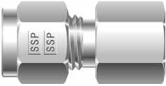
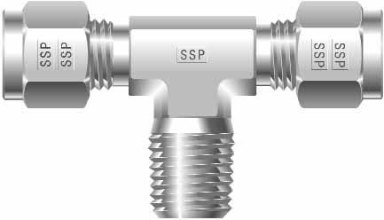
3 ow to Order IS 4 M 6 Material esignator IS=Steel SSP Brand esignator =uolok U= ube hart #1 ype of ube itting hart #2 2nd nd connection is required for a reduced size tube or a differing type of end connection such as MNP or NP. hart #1 R #1 Size esignators ube or MNP, Size esignator NP Size* 2 1/8 4 1/4 6 3/8 8 1/2 12 3/ *ube is expressed in sixteenths of an inch NOS: ll onfigurations: Only one size indicator is necessary when all of the connections are the same type and size. Straights and lbows: Specify the largest tube end first followed by the smaller tube end or differing type of connection. ees: escribed by first sizing the run (1 to 2) and then the branch (3). R #2 ype of ube itting M M MB MR M U U U BU RU R N B escription of uolok/ ube itting ypes Male onnector Male lbow Male Branch ee Male Run ee Male dapter emale onnector emale lbow emale dapter Union Union lbow Union ee Bulkhead Union Reducing Union Reducer/dapter OMPONNS Nut Back errule (uolok Only) ront errule (uolok Only) errule ( Only)
4 uolok Steel ube ittings MRILS SL uolok straight configuration tube fittings are machined from cold-finished bar stock in accordance with SM Shaped bodies are machined from close-grained steel forgings with material in accordance with SM -108 and SM PLIN & OIN uolok fittings are plated for corrosion resistance with zinc. Other chemically-inert platings may be utilized to assist installation. SIN uolok tube fittings are designed and manufactured to provide a reliable, leak-proof connection in instrumentation and process tubing systems. uolok tube fittings consist of four precision-machined components: 1) Body 2) ront errule 3) Back errule (316 SS) 4) Nut he double ferrule design, with the staged sequential swaging action of the ferrules during make-up, compensates for the variations in tubing materials, hardness, and thickness of the tube wall to provide leak-tight connections in an extensive range of applications. dditionally, in fulfillment of the design criteria, all uolok components are manufactured with stringent tolerances and superior surface finishes under rigorous quality control standards to assure the optimum performance of each component. OPRION hrough the critical interaction of precision-machined fitting components with the process tube, a leaktight seal is achieved. he simple geometric rotation of the uolok nut provides the axial thrust necessary to swage the ferrules to the outside diameter of the tube. o eliminate any potential stress on an existing system, the tube fittings have been designed to not transmit installation torque from the tube fitting to the tubing. uring the rotary movement of the nut, the internal surface of the nut meets with the rear surface of the back ferrule to axially move the back ferrule forward against the rear angle of the front ferrule. Simultaneously, the front ferrule is driven forward into the angular section of the fitting body where the desired lift to seal action of the front ferrule occurs. he back ferrule locks on the outside diameter of the tube to complete the sealing action and secure the tube within the fitting. he resulting engineered gap between the front and back ferrule is designed to help compensate for exposure to system variables such as vibration, pressure pulsation and thermal expansion/contraction. QULIY SSP's Quality System has been certified to conform to the ISO 9001:2000 Quality Standard. chievement of this prestigious status further confirms SSP's continuing commitment to quality which is reflected throughout the company in its personnel, policies, equipment, products and service. In addition, all uolok tube fittings are manufactured to the technical design specifications and rigid quality control standards of SSP. RI Statistical Process ontrol techniques are employed within the manufacturing process to supply timely, meaningful feedback to the production team. ontinual process monitoring and equipment control provide the necessary manufacturing quality for uolok instrumentation grade tube fittings. 4
 from entering the fitting prior to its use, and help to retain the integrity of the factory assembled body, nut, and ferrules.")
5 uolok Steel ube ittings PKIN uolok tube fittings are individually bagged to assure the highest levels of quality, safety and cleanliness. he protective bags eliminate contamination (tubing burrs, dirt, etc.) from entering the fitting prior to its use, and help to retain the integrity of the factory assembled body, nut, and ferrules. MPRUR ORS uolok tube fittings function reliably in applications ranging from cryogenic temperatures to high temperature bake out with the tube fitting material as the limiting factor. It is important to note that elevated temperatures will reduce the maximum working pressure capability of the tubing system. BILIY uolok tube fittings are designed, manufactured and quality controlled to be gageable for sufficient pull-up during initial installation. See page 9 for additional information. LIIM WRRNY uolok tube fittings are covered by a published Lifetime Warranty as printed on the inside back cover of this catalog. UB SLION areful selection and specification of tubing is essential to the performance of a tubing system. When choosing the appropriate tubing material, size and wall thickness, consideration must be given to the system s environment, pressures, temperatures and flows. s long as a uolok tube fitting is in its original protective bag, it is identified as factory new, completely assembled and ready for installation. dditionally, for efficient product identification and storage, the uolok tube fittings are packaged in boxes that are color-coded to the tube fittings' material of construction and have pictorial labels which include the part number, product description and box quantity. PRSSUR RINS enerally, uolok tube fittings are rated for pressures equal to the maximum allowable working pressures of the tubing recommended for use with the fittings. owever, it is important to note that many specially designed fittings, bored-through fittings and fittings having N, O-Seal and S/MS integral ends may have lower pressure ratings than that of the tubing. INRNBILIY uolok tube fittings are designed, manufactured and quality controlled to be totally interchangeable with the Swagelok brand of tube fittings. omponent by component examination plainly shows the two brands as completely component-intermixable". he precision manufacturing of both products to stringent tolerances under rigid quality control procedures ensures the safety, performance and reliability of service whenever uolok and Swagelok component parts are mixed and used in accordance with published installation and service recommendations. Swagelok is a registered rademark of the Swagelok o. 5


6 uolok Steel ube ittings INIIL INSLLION 1. uolok tube fittings come individually bagged and completely assembled for immediate use. here is no need for disassembly prior to use. Simply remove the tube fitting from its bag, insert the tube* until it bottoms in the uolok tube fitting body and then hand tighten the uolok nut. (See igure #1.) igure #3 1-1/4 turns for sizes 1/4-1 igure #3 Back-Up Wrench 2. While holding the fitting body stable with a back-up wrench, use a wrench to rotate the uolok nut to the fitting s original installation position (approximately 1/4 turn from the hand-tight, snug position) then continue to tighten the uolok nut slightly. (See igure #5.) igure #5 *ubing ends should be cut as straight as possible with all and I.. burrs removed. Use of a tubing cutter or guide blocks with a hacksaw is recommended. igure #1 [NO: or extreme system applications using high pressures or requiring an extra factor of safety, it may be desirable to use a "common makeup starting point" to alleviate the inherent variations in tubing diameters. Installation should begin from a "snug" position, which is achieved by wrench tightening the uolok nut until the inserted tubing will not move freely by hand (approximately 1/8 turn). rom this new "snug" starting point, continue with the recommended installation instructions.] 2. While holding the fitting body stable with a back-up wrench, scribe the nut for a reference point and wrench tighten the nut 1-1/4 turns for sizes 1/4" - 1" and 3/4 turn for sizes 1/16"- 3/16". (See igures #2 and #3.) igure #2 Only 3/4 of a turn for sizes 1/16-3/16 [NO: or all sizes, tighten plugs (P), machined ferrule end of port connector (P) and the uolok end of the emale N adapter (N) only 1/4 of a turn. ube fittings in sizes over 1 require the use of the SSP Instrumentation ydraulic Swaging ool for installation. ontact your uthorized SSP Instrumentation istributor for more information.] RSSMBLY INSRUIONS Back-Up Wrench 1. o reassemble a uolok tube fitting connection, simply insert the tubing with the previously swaged ferrules and uolok nut into the fitting body until the front ferrule seats within the fitting body, and then tighten the nut by hand. (See igure #4.) [NO: By following proper reassembly procedures, uolok tube fitting connections may be disconnected and reconnected repeatedly.] rom original installation position, tighten slightly OMPONN SSMBLY Should individual component assembly of a uolok tube fitting ever be required, careful attention must be given to the proper sequence and direction of the uolok components. (See igure #6.) Nut Back errule ront errule Body 6 Back-Up Wrench


7 uolok Steel ube ittings he uolok pre-setting tool is used to pre-set the ferrules on the tubing for subsequent installation in a fitting body. he pre-setting tool can be especially helpful when an installation must be made in a tight space or hard-to-work area. he presetting tool allows the major portion of the installation work to occur in a more favorable work setting with only the completion of the installation in the hard-to-work area. PR-SIN INSRUIONS 1. Secure the pre-setting tool in a vise. 2. Remove the protective nut, and assemble the uolok nut and ferrules loosely to the pre-setting tool. Insert the tubing through the nut and ferrules until it bottoms in the pre-setting tool, and then follow the standard uolok tube fitting installation instructions. (See igure #7 and #7B) igure #7 igure #7B 3. Loosen the nut and remove the tubing with the pre-set uolok ferrules and nut from the pre-setting tool. (See igure #8.) Return the protective nut to the presetting tool. igure #8 4. Installation of the tubing, with the pre-set uolok ferrules and nut in the appropriate fitting body, can now be made by following the standard reassembly instructions. (See igure #9 and #9B.) igure #9 igure #9B NO: o extend the life of a presetting tool, lubricate the tool with a lubricant compatible with the system s tubing material, environment and media. lso, at times an oversized or very soft tubing may tend to stick in the presetting tool after make up. o remove the tubing, gently rock the tube back and forth. Never turn the tube with pliers or another tool as such action may damage the sealing surfaces. BILIY Back-Up Wrench ach uolok tube fitting component is manufactured with utmost precision to provide the optimum performance interaction of the components during assembly. By maintaining such stringent manufacturing tolerances, the uolok tube fittings are considered gageable for sufficient pull-up during initial installation. he uolok "ap ages" are designed to identify for the installer or inspector, prior to pressurizing a system, that sufficient tightening of the tube fitting has occurred. ageability provides additional reliability for proper installation and ultimate tube fitting safety and performance. UOLOK P INSRUIONS 1. ollow proper installation instructions (as supplied with the fittings, or published in the uolok catalog). 2. fter completion of the installation instructions and prior to pressuring the system, choose the proper size ap age and try to insert it between the fitting's nut and body hex. (See igure #10) 3. If the ap age will not enter between the fitting's nut and body hex, no additional tightening is required. 4. If the ap age will enter between the fitting's nut and body hex, additional tightening is required. Note: Swagelok and Parker -LOK ap Inspection ages may also be utilized effectively with uolok tube fittings. No additional tightening required. dditional tightening required. Swagelok is a registered trademark of the Swagelok ompany. -Lok is a registered trademark of Parker annifin o. 7
8 Steel ube ittings MRILS OPRION QULIY SL straight configuration tube fittings are machined from cold-finished bar stock in accordance with SM Shaped bodies are machined from close-grained steel forgings with material in accordance with SM -108 and SM PLIN & OIN fittings are plated for corrosion resistance with zinc. ferrule is coated with phosphate for lubricity. Other chemically-inert platings may be utilized to assist installation. SIN tube fittings are designed and manufactured to provide a reliable, leak-proof connection in instrumentation and process tubing systems. tube fittings consist of three precisely machined components: 1) Body 2) errule 3) Nut he single ferrule design, with the spring-like action of the ferrule during make-up, compensates for the variations in tubing materials, hardness, and thickness of the tube wall to provide leak-tight connections in an extensive range of applications. dditionally, in fulfillment of the design criteria, all components are manufactured with extremely tight tolerances and superior surface finishes under rigorous quality control standards to assure the optimum performance of each component part. hrough the critical interaction of the precisely machined fitting components with the process tube, a leaktight seal is achieved. he simple geometric rotation of the nut provides the axial thrust necessary to coin the ferrule to the outside diameter of the tube. o eliminate any potential stress on an existing system, the tube fittings have been designed to not transmit installation torque from the tube fittings to the tubing. uring the rotary movement of the nut, the internal surface of the nut meets with the rear surface of the ferrule to axially move the ferrule forward into the angular section of the fitting body. he leading edge of the ferrule is directed into the tube to begin the required bowing action of the ferrule. Subsequently, the leading edge of the ferrule locks on the outside diameter of the tube to complete the sealing action and secure the tube within the fitting. he resulting spring-like action of the ferrule is designed to help compensate for exposure to system variables such as vibration, pressure pulsation and thermal expansion/contraction. SSP's Quality System has been certified to conform to the ISO 9001:2000 Quality Standard. chievement of this prestigious status further confirms SSP's continuing commitment to quality which is reflected throughout the company in its personnel, policies, equipment, products and service. In addition, all tube fittings are manufactured to the technical design specifications and rigid quality control standards of SSP. RI Statistical Process ontrol techniques are employed within the manufacturing process to supply timely, meaningful feedback to the production team. ontinual process monitoring and equipment control provide the necessary manufacturing quality for instrumentation grade tube fittings. 8
 from entering the fitting prior to its use, and help to retain the integrity of the factory assembled body, nut, and ferrule.")
9 Steel ube ittings PKIN tube fittings are individually bagged to assure the highest levels of quality, safety and cleanliness. he protective bags eliminate contamination (tubing burrs, dirt, etc.) from entering the fitting prior to its use, and help to retain the integrity of the factory assembled body, nut, and ferrule. s long as a tube fitting is in its original protective bag, it is identified as factory new, completely assembled and ready for installation. MPRUR ORS tube fittings function reliably in applications ranging from cryogenic temperatures to high temperature bake out with the tube fitting material as the limiting factor. It is important to note that elevated temperatures will reduce the maximum working pressure capability of the tubing system. BILIY tube fittings are designed, manufactured and quality controlled to be gageable for sufficient pull-up during initial installation. INRNBILIY LIIM WRRNY tube fittings are covered by a published Lifetime Warranty as printed on the inside back cover of this catalog. UB SLION areful selection and specification of tubing is essential to the performance of a tubing system. When choosing the appropriate tubing material, size and wall thickness, consideration must be given to the system s environment, pressures, temperatures and flows. he individually bagged tube fittings are packaged in convenient, small-lot quantities for easy procurement and handling. dditionally, for efficient product identification and storage, the boxes are color-coded to the tube fittings' material of construction and have pictorial labels which include the part number, product description and box quantity. PRSSUR RINS enerally, tube fittings are rated for pressures equal to the maximum allowable working pressures of the tubing recommended for use with the fittings. owever, it is important to note that many specially designed fittings, bored-through fittings and fittings having N, O-Seal and S/MS integral ends may have lower pressure ratings than that of the tubing. tube fittings are designed, manufactured and quality controlled to be totally interchangeable with the Parker PI M brand of tube fittings. omponent by component examination plainly shows the two brands as completely componentintermixable". he precision manufacturing of both products to stringent tolerances under rigid quality control procedures ensures the safety, performance and reliability of service whenever and Parker PI component parts are mixed and used in accordance with published installation and service recommendations. dditionally, tube fittings are considered able to be "functionally interchangeable" with the Swagelok brand of tube fitting. "unctionally interchangeable" allows for the use of a nut and/or ferrule with a Swagelok body, or a Swagelok nut and/or ferrule system with a body. he exceptional quality characteristics of both product lines assure complete product performance whenever the two brands are "functionally interchanged". Swagelok is a registered rademark of the Swagelok o. PI is a registered trademark of Parker annifin o. 9

")
10 Steel ube ittings INIIL INSLLION 1. tube fittings come individually bagged and completely assembled for immediate use. here is no need for disassembly prior to use. Simply remove the tube fitting from its bag, insert the tube* until it bottoms in the tube fitting body and then hand tighten the nut. See igure #1. igure #1 igure #3 1-1/4 turns for sizes 1/4-1 igure #3 Back-Up Wrench 2. While holding the fitting body stable with a back-up wrench, use a wrench to rotate the nut to the fitting s original installation position (approximately 1/4 turn from the hand-tight, snug position) then continue to tighten the nut slightly. See igure #5. igure #4 *ubing ends should be cut as straight as possible with all and I.. burrs removed. Use of a tubing cutter or guide blocks with a hacksaw is recommended. [NO: or extreme system applications using high pressures or requiring an extra factor of safety, it may be desirable to use a "common makeup starting point" to alleviate the inherent variations in tubing diameters. Installation should begin from a "snug" position, which is achieved by wrench tightening the nut until the inserted tubing will not move freely by hand (approximately 1/8 turn). rom this new "snug" starting point, continue with the recommended installation instructions.] 2. While holding the fitting body stable with a back-up wrench, scribe the nut for a reference point and wrench tighten the nut 1-1/4 turns for sizes 1/4" - 1" and 3/4 turn for sizes 1/16"- 3/16". See igures #2 and #3. igure #2 Only 3/4 of a turn for sizes 1/16-3/16 [NO: or all sizes, tighten plugs (P), machined ferrule end of port connector (P) and the end of the emale N dapter (N) only 1/4 of a turn.] RSSMBLY INSRUIONS 1. o reassemble a tube fitting connection, simply insert the tubing with the previously swaged ferrule and nut into the fitting body until the ferrule seats within the fitting body, and then tighten the nut by hand. See igure #4. igure #4 Back-Up Wrench [NO: By following proper reassembly procedures, tube fitting connections may be disconnected and reconnected repeatedly.] rom original installation position, tighten slightly OMPONN SSMBLY Should individual component assembly of a tube fitting ever be required, careful attention must be given to the proper sequence and direction of the components. See igure #6. Nut errule Body Back-Up Wrench 10


 igure #7 igure #7B 3. Loosen the nut and remove the tubing with the pre-set ferrule and nut from the pre-setting tool. (See igure #8.")

11 Steel ube ittings he pre-setting tool is used to pre-set the ferrule on the tubing for subsequent installation in a fitting body. he pre-setting tool can be especially helpful when an installation must be made in a tight space or hard-to-work area. he presetting tool allows the major portion of the installation work to occur in a more favorable work setting with only the completion of the installation in the hard-to-work area. PR-SIN INSRUIONS 1. Secure the pre-setting tool in a vise. 2. Remove the protective nut, and assemble the nut and ferrule loosely to the pre-setting tool. Insert the tubing through the nut and ferrule until it bottoms in the pre-setting tool, and then follow the standard tube fitting installation instructions from page 8. (See igures #7 and #7B) igure #7 igure #7B 3. Loosen the nut and remove the tubing with the pre-set ferrule and nut from the pre-setting tool. (See igure #8.) Return the protective nut to the presetting tool. igure #8 4. Installation of the tubing, with the pre-set ferrule and nut in the appropriate fitting body, can now be made by following the standard reassembly instructions from page 8. (See igures #9 and #9B.) igure #9 igure #9B Back-Up Wrench NO: o extend the life of a pre-setting tool, lubricate the tool with a lubricant compatible with the system s tubing material, environ-ment and media. lso, at times an oversized or very soft tubing may tend to stick in the presetting tool after make up. o remove the tubing, gently rock the tube back and forth. Never turn the tube with pliers or another tool as such action may damage the sealing surfaces. BILIY ach tube fitting component is manufactured with utmost precision to provide the optimum performance interaction of the components during assembly. By maintaining such stringent manufacturing tolerances, the tube fittings are considered gageable for sufficient pull-up during initial installation. he "ap ages" are designed to identify for the installer or inspector, prior to pressurizing a system, that sufficient tightening of the tube fitting has occurred. ageability provides additional reliability for proper installation and ultimate tube fitting safety and performance. UNILOK P INSRUIONS 1. ollow proper installation instructions (as supplied with the fittings, or published in the catalog). 2. fter completion of the installation instructions and prior to pressuring the system, choose the proper size ap age and try to insert it between the fitting's nut and body hex. (See igure #10) 3. If the ap age will not enter between the fitting's nut and body hex, no additional tightening is required. 4. If the ap age will enter between the fitting's nut and body hex, additional tightening is required. Note: Parker PI Inspection auges may also be utilized effectively with tube fittings. No additional tightening required. dditional tightening required. PI is a registered trademark of Parker annifin o. 11


12 uolok Steel ube ittings ube to Male Pipe Male onnector Male lbow Male Branch ee Male Run ee Male dapter M 14 M 14 MB 15 MR 15 M 16 ube to emale Pipe emale onnector ube to ube Union Union Union lbow ap & Plug ap emale lbow 17 U Union ee 19 U 19 Bulkhead Union P Plug 22 emale dapter 17 U 20 BU 20 Reducing Union Reducer/dapter P RU 21 R 21 omponents Nut Back errule ront errule 12 N 22 B 22 22
13 Steel ube ittings ube to Male Pipe Male onnector Male lbow Male Branch ee Male Run ee Male dapter M 23 M 23 MB 24 MR 24 M 25 ube to emale Pipe ube to ube Union ap & Plug emale onnector Union Union lbow ap emale lbow 26 U Union ee 28 U Bulkhead Union 28 P Plug 24 emale dapter 26 U Reducing Union 29 BU Reducer/dapter 29 P RU 30 R 30 omponents Nut errule N
14 uolok Steel ube ittings BOY X NU X B-BOY P-PIP R Male onnector (M) uolok ube P-NP Male Pipe Size B Min. 4M2 1/4 1/ /16 1/2 4M4 1/4 1/ /16 1/2 4M6 1/4 3/ /16 11/16 4M8 1/4 1/ /16 7/8 6M2 3/8 1/ /16 5/8 6M4 3/8 1/ /16 5/8 6M6 3/8 3/ /16 11/16 6M8 3/8 1/ /16 7/8 8M4 1/2 1/ /8 13/16 8M6 1/2 3/ /8 13/16 8M8 1/2 1/ /8 7/8 12M12 3/4 3/ /8 1-1/16 16M /2 1-3/8 NU X -WRN P By P-PIP R Male lbow (M) uolok ube P-NP Male Pipe Size By 4M2 1/4 1/ /16 1/2 4M4 1/4 1/ /16 1/2 6M4 3/8 1/ /16 5/8 6M6 3/8 3/ /16 11/16 6M8 3/8 1/ /16 7/8 8M4 1/2 1/ /8 13/16 8M6 1/2 3/ /8 13/16 8M8 1/2 1/ /8 7/8 12M12 3/4 3/ /8 1-1/16 16M /2 1-3/8 Min. 14 inger -tight assembly dimensions (shown in inches) are for reference only and subject to change.
15 uolok Steel ube ittings B-BOY NU X By -WRN P P-PIP R Male Branch ee (MB) uolok ube P-NP Male Pipe Size x B By 4MB2 1/4 1/ /16 1/2 4MB4 1/4 1/ /16 9/16 6MB4 3/8 1/ /16 5/8 8MB8 1/2 1/ /8 7/8 x Min. x NU X B-BOY P-PIP R x -WRN P Male Run ee (MR) uolok ube P-NP Male Pipe Size x B By 4MR2 1/4 1/ /16 1/2 4MR4 1/4 1/ /16 9/16 6MR4 3/8 1/ /16 5/8 8MR8 1/2 1/ /8 7/8 x Min. By inger -tight assembly dimensions (shown in inches) are for reference only and subject to change. 15
16 uolok Steel ube ittings B P-PIP R Male dapter (M) uolok ube P-NP Male Pipe Size B Min. 4M2 1/4 1/ /16 4M4 1/4 1/ /16 4M6 1/4 3/ /16 4M8 1/4 1/ /8 6M2 3/8 1/ /16 6M4 3/8 1/ /16 6M6 3/8 3/ /16 6M8 3/8 1/ /8 8M4 1/2 1/ /16 8M6 1/2 3/ /16 8M8 1/2 1/ /8 8M12 1/2 3/ /16 12M8 3/4 1/ /8 12M12 3/4 3/ /16 12M16 3/ /8 16M8 1 1/ /16 16M12 1 3/ /16 16M /8 Union ee Male dapter Male Run ee Male dapter fittings allow any uolok tube fitting connection to be converted to connect to female NP 16 inger -tight assembly dimensions (shown in inches) are for reference only and subject to change.
17 uolok Steel ube ittings NU X B-BOY BOY X P-PIP R emale onnector () uolok ube P-NP emale Pipe Size B 42 1/4 1/ /16 9/ /4 1/ /16 3/4 64 3/8 1/ /16 3/4 66 3/8 3/ /16 7/8 86 1/2 3/ /8 7/8 88 1/2 1/ /8 1-1/16 NU X -BOY -WRN P By emale lbow () P-PIP R uolok ube P-NP emale Pipe Size By 42 1/4 1/ /16 1/2 44 1/4 1/ /16 11/ /8 1/ /16 11/ /2 1/ /8 1 inger -tight assembly dimensions (shown in inches) are for reference only and subject to change. 17
18 uolok Steel ube ittings P-PIP R X B emale dapter () uolok ube P-NP emale Pipe Size B Min. 42 1/4 1/ / /4 1/ /4 46 1/4 3/ /8 48 1/4 1/ / /8 1/ / /8 1/ /4 66 3/8 3/ /8 68 3/8 1/ / /2 1/ /4 86 1/2 3/ /8 88 1/2 1/ / /2 3/ / /4 1/ / /4 3/ / / / / / / / /8 Union ee emale dapter emale Run ee emale dapter fittings allow any uolok tube fitting connection to be converted to connect to male NP 18 inger -tight assembly dimensions (shown in inches) are for reference only and subject to change.
19 uolok Steel ube ittings -BOY X B-BOY NU X Union (U) uolok ube B 4U 1/ /16 1/2 6U 3/ /16 5/8 8U 1/ /8 13/16 12U 3/ /8 1-1/16 16U /2 1 3/8 NU X -WRN P Union lbow (U) uolok ube 4U 1/ /16 1/2 6U 3/ /16 5/8 8U 1/ /8 13/16 12U 3/ /8 1-1/16 16U /2 1-3/8 inger -tight assembly dimensions (shown in inches) are for reference only and subject to change. 19
20 uolok Steel ube ittings B-BOY NU X x -WRN P Union ee (U) x x uolok ube x B 4U 1/ /16 1/2 6U 3/ /16 5/8 8U 1/ /8 13/16 12U 3/ /8 1-1/16 16U /2 1-3/8 NU X B-BOY -BOY X Bulkhead Union (BU) uolok ube x B -JM NU X x Maximum Panel hickness Panel ole rill Size 4BU 1/ /16 5/ /64 6BU 3/ /16 3/ /64 8BU 1/ /8 15/ /64 20 inger -tight assembly dimensions (shown in inches) are for reference only and subject to change.
21 uolok Steel ube ittings NU X B-BOY -BOY X NU X x x Reducing Union (RU) x x uolok ube x ube B x x x 6RU4 3/8 1/ /16 9/16 5/8 8RU4 1/2 1/ /8 9/16 13/16 8RU6 1/2 3/ /8 11/16 13/16 NU X UB I. B-BOY x Reducer/dapter (R) -BOY X uolok ube x B 4R6 1/4 3/ /16 1/2 4R8 1/4 1/ /16 9/16 6R4 3/8 1/ /16 5/8 6R8 3/8 1/ /16 5/8 8R12 1/2 3/ /8 13/16 inger -tight assembly dimensions (shown in inches) are for reference only and subject to change. 21
22 uolok Steel ube ittings ap () NU X B-BOY BOY X uolok ube B 4P 1/ /16 1/2 6P 3/ /16 5/8 8P 1/ /8 13/16 aps are used for capping the end of a tubing run. ap Installation Instructions he standard uolok fitting installation instructions apply for proper installation of caps (see page 6). Plug (P) NU X uolok Part# ube 4P 1/4 9/16 6P 3/8 11/16 8P 1/2 7/8 Plugs are used to plug an unused port of a uolok tube fitting. Plug Installation Instructions 1. Remove nut and ferrules from the port of the tube fitting body to be plugged and replace with the uolok plug. 2. and- tighten the uolok plug and then while holding the tube fitting body steady with a back-up wrench, use a wrench to tighten the uolok plug only 1/4 of a turn. Nut (N) NU X uolok ube L 4N 1/4 9/ N 3/8 11/ N 1/2 7/ N 3/4 1-1/ N 1 1-1/ L 22 ront errule () uolok ube IS4 1/4 IS6 3/8 IS8 1/2 IS12 3/4 IS16 1 Back errule (B) uolok ube ISS4B 1/4 ISS6B 3/8 ISS8B 1/2 ISS12B 3/4 ISS16B 1 inger -tight assembly dimensions (shown in inches) are for reference only and subject to change.

23 Steel ube ittings NU X B-BOY BOY X Male onnector (M) P-PIP R ube P-NP Male Pipe Size B U4M2 1/4 1/ /16 1/2 U4M4 1/4 1/ /16 9/16 U4M6 1/4 3/ /16 11/16 U4M8 1/4 1/ /16 7/8 U6M2 3/8 1/ /16 5/8 U6M4 3/8 1/ /16 5/8 U6M6 3/8 3/ /16 1-1/16 U6M8 3/8 1/ /16 7/8 U8M4 1/2 1/ /8 13/16 U8M6 1/2 3/ /8 13/16 U8M8 1/2 1/ /8 7/8 U12M12 3/4 3/ /8 1-1/16 U16M /2 1-3/8 Min. NU X -WRN P By Male lbow (M) ube P-NP MalePipe Size By U P-PIP R Min. U4M2 1/4 1/ /16 1/2 U4M4 1/4 1/ /16 1/2 U6M4 3/8 1/ /16 5/8 U6M6 3/8 3/ /16 11/16 U6M8 3/8 1/ /16 7/8 U8M4 1/2 1/ /8 13/16 U8M6 1/2 3/ /8 13/16 U8M8 1/2 1/ /8 7/8 U12M12 3/4 3/ /8 1-1/16 U16M /2 1-3/8 inger -tight assembly dimensions (shown in inches) are for reference only and subject to change. 23
24 Steel ube ittings B-BOY NU X By -WRN P Male Branch ee (MB) ube P-NP Male Pipe Size x B By U U4MB2 1/4 1/ /16 1/2 U4MB4 1/4 1/ /16 9/16 U6MB4 3/8 1/ /16 5/8 U8MB8 1/2 1/ /8 7/8 x Min. P-PIP R x NU X B-BOY P-PIP R x -WRN P Male Run ee (MR) ube P-NP Male Pipe Size x B By U4MR2 1/4 1/ /16 1/2 U4MR4 1/4 1/ /16 9/16 U6MR4 3/8 1/ /16 5/8 U8MR8 1/2 1/ /8 7/8 x Min. By 24 inger -tight assembly dimensions (shown in inches) are for reference only and subject to change.

25 Steel ube ittings P-PIP R B Male dapter (M) ube P-NP Male Pipe Size B Min. U4M2 1/4 1/ /16 U4M4 1/4 1/ /16 U4M6 1/4 3/ /16 U4M8 1/4 1/ /8 U6M2 3/8 1/ /16 U6M4 3/8 1/ /16 U6M6 3/8 3/ /16 U6M8 3/8 1/ /8 U8M4 1/2 1/ /16 U8M6 1/2 3/ /16 U8M8 1/2 1/ /8 U8M12 1/2 3/ /16 U12M8 3/4 1/ /8 U12M12 3/4 3/ /16 U12M16 3/ /8 U16M8 1 1/ /16 U16M12 1 3/ /16 U16M /8 Union ee Male dapter Male Run ee Male dapter fittings allow any tube fitting connection to be converted to connect to female NP inger -tight assembly dimensions (shown in inches) are for reference only and subject to change. 25

26 Steel ube ittings NU X B-BOY BOY X emale onnector () P-PIP R ube P-NP emale Pipe Size B U42 1/4 1/ /16 9/16 U44 1/4 1/ /16 3/4 U64 3/8 1/ /16 3/4 U66 3/8 3/ /16 7/8 U86 1/2 3/ /8 7/8 U88 1/2 1/ /8 1-1/16 NU X -BOY -WRN P By emale lbow () P-PIP R ube P-NP emale Pipe Size By U42 1/4 1/ /16 1/2 U44 1/4 1/ /16 11/16 U64 3/8 1/ /16 11/16 U88 1/2 1/ / inger -tight assembly dimensions (shown in inches) are for reference only and subject to change.

 are for")
27 Steel ube ittings P-PIP R X B emale dapter () ube P-NP emale Pipe Size B U42 1/4 1/ /16 U44 1/4 1/ /4 U46 1/4 3/ /8 U48 1/4 1/ /16 U62 3/8 1/ /16 U64 3/8 1/ /4 U66 3/8 3/ /8 U68 3/8 1/ /16 U84 1/2 1/ /4 U86 1/2 3/ /8 U88 1/2 1/ /16 U812 1/2 3/ /16 U128 3/4 1/ /16 U1212 3/4 3/ /16 U1216 3/ /8 U / /16 U / /4 U /8 Union ee emale dapter emale Run ee emale dapter fittings allow any tube fitting connection to be converted to connect to male NP inger -tight assembly dimensions (shown in inches) are for reference only and subject to change. 27
 ube U4U 1/4 1.06 0.77 0.70 0.60 0.19 9/16 1/2 U6U 3/8 1.20 0.91 0.76 0.66 0.")
28 Steel ube ittings -BOY X B-BOY NU X Union (U) ube B U4U 1/ /16 1/2 U6U 3/ /16 5/8 U8U 1/ /8 13/16 U12U 3/ /8 1-1/16 U16U /2 1-3/8 NU X -WRN P Union lbow (U) ube U4U 1/ /16 1/2 U6U 3/ /16 5/8 U8U 1/ /8 13/16 U12U 3/ /8 1-1/16 U16U /2 1-3/8 28 inger -tight assembly dimensions (shown in inches) are for reference only and subject to change.
29 Steel ube ittings B-BOY NU X x -WRN P x x Union ee (U) ube x B U4U 1/ /16 1/2 U6U 3/ /16 5/8 U8U 1/ /8 13/16 U12U 3/ /8 1/16 U16U /2 1-3/8 NU X B-BOY -BOY X -JM NU X x Bulkhead Union (BU) ube x B Maximum Panel hickness Panel ole rill Size U4BU 1/ /16 5/ /64 U6BU 3/ /16 3/ /64 U8BU 1/ /8 15/ /64 inger -tight assembly dimensions (shown in inches) are for reference only and subject to change. 29
30 Steel ube ittings NU X B-BOY -BOY X NU X x x x x Reducing Union (RU) ube x ube B x x x U6RU4 3/8 1/ /16 9/16 5/8 U8RU4 1/2 1/ /8 9/16 13/16 U8RU6 1/2 3/ /8 11/16 13/16 NU X UB I. B-BOY x Reducer/dapter (R) -BOY X ube x B U4R6 1/4 3/ /16 1/2 U4R8 1/4 1/ /16 9/16 U6R4 3/8 1/ /16 5/8 U6R8 3/8 1/ /16 5/8 U8R12 1/2 3/ /8 13/16 30 inger -tight assembly dimensions (shown in inches) are for reference only and subject to change.
31 Steel ube ittings ap (P) ube B U4P 1/ U6P 3/ U8P 1/ aps are used for capping the end of a tubing run. ap Installation Instructions he standard fitting installation instructions apply for proper installation of caps (see page 10). V NU X B-BOY BOY X Plug (P) ube NU X U4P 1/4 9/16 U6P 3/8 11/16 U8P 1/2 7/8 Plugs are used to plug an unused port of a tube fitting. Plug Installation Instructions 1. Remove nut and ferrules from the port of the tube fitting body to be plugged and replace with the plug. 2. and- tighten the plug and then while holding the tube fitting body steady with a back-up wrench, use a wrench to tighten the plug only 1/4 of a turn. Nut (N) NU X ube L U4N 1/4 9/ U6N 3/8 11/ U8N 1/2 7/ U12N 3/4 1-1/ U16N 1 1-1/ L errule () ube ISU4 1/4 ISU6 3/8 ISU8 1/2 ISU12 3/4 ISU16 1 inger -tight assembly dimensions (shown in inches) are for reference only and subject to change. Sizes 4 & 6 Size 8 31
32 Pressures, ittings and ubing ube Size (in.) RBON SL UBIN Maximum llowable Working Pressure (PSI) Wall hickness of ube (Inches) / / / / / / / / / Note: or light gas service, use tubing with wall thickness outside of shaded area. alculation Basis: nnealed, seamless carbon steel tubing SM -179 or equivalent. System temperatures between -20 and +100 with allowable stress of 15,700 psi. Safety factor of 4. Reference: NSI B 31.3 ode. (or more specific working pressure information regarding a particular tubing, consult the tubing manufacturer.) Suggested ube Ordering Information: Specify the outside diameter and wall thickness of annealed, seamless carbon steel tubing of SM -179 or equivalent specification. lso specify high quality tubing to be free of scratches, and suited for bending with material hardness not to exceed Rb 72. SSP NP PIP N PRSSUR RINS, NSI/SM B31.3 NP/ISO Male emale Size Pipe Size psig bar psig bar 1/16" /8" /4" /8" /2" /4" " Reference: bar=.0695 X psig o obtain NSI/SM B 31.1 values, multiply above values by 0.85 R SL R Radius of tubing bend as required or minimum alloed for specified wall thickness and tube size as recommended by tubing manufacturer. INSLLIN UB IINS NR UB BNS When installing fittings near tube bends, it is important to bend tubing prior to installing tube fittings and there must be a sufficient straight length (SL) of tubing to allow the tube to be bottomed in the fitting. See table below. =ube (in.) 1/16 1/8 3/16 1/4 5/16 3/8 1/2 5/8 3/4 7/ /4 1-1/2 2 SL straight tube *SL= length required from end of tube Straight 1/2 3/4 3/4 13/16 7/8 15/16 1-3/16 1-1/4 1-1/4 1-5/16 1-9/ /32 3-1/4 to beginning of bend. Length of ube ube outside diameter (in.) R Radius of tube bend as recommended by bender manufacturer *onsult the factory on an application by application basis for variance. IMPROPR SLION OR IMPROPR US O PROUS SRIB RIN OR RL IMS N US PRSONL INJURY N PROPRY M. 32 WRNIN It is the sole responsibility of the system designers to properly select and use the products for their specific applications. his document has been printed for users with technical expertise as a reference for further investigation to determine specific product needs relative to design requirements.
33 Warranty uolok ube ittings Lifetime Limited Warranty SSP guarantees all uolok tube fittings and uolok tube fitting components to be free from defects in materials and workmanship. dditionally, SSP guarantees uolok product performance to the published catalog specifications when properly installed according to the catalog selection and installation instructions. o initiate a warranty claim, suspected defective product must be returned to SSP with the nature of potential defect documented for factory evaluation. ny product with a determined defect in material or workmanship will be replaced with equivalent product at no charge. his warranty comprises the sole and entire warranty pertaining to items provided hereunder. here is no other warranty, guarantee, express or implied representation of any kind whatsoever. ll other warranties including, but not limited to, merchantability and fitness for purpose, whether express, implied, or arising by operation of law, course of dealing, or trade usage are hereby disclaimed. here are no warranties which extend beyond the description on the face hereof; and this warranty does not apply in cases of abuse, mishandling, or normal use depreciation. In no event, whether alleged to arise from breach of contract, express or implied warranty, by operation of law, negligence or otherwise, will SSP be liable for any incidental, consequential, lost property, or other special damages of any kind whatsoever. he exclusive, only remedy under this warranty is the replacement of determined defective parts as set forth above. uolok ube ittings LIIM LIMI WRRNY ube ittings Lifetime Limited Warranty SSP guarantees all tube fittings and tube fitting components to be free from defects in materials and workmanship. dditionally, SSP guarantees product performance to the published catalog specifications when properly installed according to the catalog selection and installation instructions. o initiate a warranty claim, suspected defective product must be returned to SSP with the nature of potential defect documented for factory evaluation. ny product with a determined defect in material or workmanship will be replaced with equivalent product at no charge. his warranty comprises the sole and entire warranty pertaining to items provided hereunder. here is no other warranty, guarantee, express or implied representation of any kind whatsoever. ll other warranties including, but not limited to, merchantability and fitness for purpose, whether express, implied, or arising by operation of law, course of dealing, or trade usage are hereby disclaimed. here are no warranties which extend beyond the description on the face hereof; and this warranty does not apply in cases of abuse, mishandling, or normal use depreciation. In no event, whether alleged to arise from breach of contract, express or implied warranty, by operation of law, negligence or otherwise, will SSP be liable for any incidental, consequential, lost property, or other special damages of any kind whatsoever. he exclusive, only remedy under this warranty is the replacement of determined defective parts as set forth above. ube ittings LIIM LIMI WRRNY 33
34 SSP Steel ube ittings SOK N SUPPOR LOLLY BY: 8250 Boyle Parkway winsburg, Ohio elephone: (330) ax: (330) RI 100% Made in the US ILSUP/000/06
Griplok. Tube Fittings. Quality Instrumentation Fittings
 ube ittings Quality Instrumentation ittings ompany Information 1926 SSP ittings orp. is founded in leveland, Ohio, U.S.. SSP begins as a contract manufacturer of screw machine products in brass and carbon
Made in USA. Unilok. Tube Fittings. QUALITY INSTRUMENTATION FITTINGS
 Unilok Tube Fittings Made in USA www.sspfittings.com QUALITY INSTRUMENTATION FITTINGS SSP Fittings Corp. / SSP Instrumentation Table of Contents How to Order...3 Tube Fittings Selection Guide... 4-6 Unilok
Swagelok Medium-Pressure, Gaugeable Tube Fit tings and Adapte r Fit tings
 www.swagelok.com Swagelok Medium-Pressure, Gaugeable Fit tings and dapte r Fit tings For Pre s sure s up to 15 0 0 0 psig (1034 ba r) asy installation, no special tools required ssembly by one full turn
COMPRESSION TUBE FITTINGS 1/16 THROUGH 2 2 MM THROUGH 50 MM
 OMPRSSION U IINS 1/16 ROU 2 2 MM ROU 50 MM L-LOK U IINS SRIPION L-LOK O OS I ORK? he L-LOK tube fitting is a mechanism used both to seal and to grip tubing. he mechanical advantage and geometry of this
Table Of Contents. Assembly Instructions. Identification of Sync-Lok Tube Fittings. Reducing Port Connector 36. Male Elbow 11
 able Of Contents eneral Information 1 Union Cross 27 Ordering Information 3 Reducer 28 ube Selection Data 5 Bulkhead Reducer 29 Male Connector 7 Male Adapter 31 Male Bore hrough Connector 9 emale Adapter
Gaugeable Alloy 400 Mechanically Attached Pipe and Tube Fittings
 www.swagelok.com Gaugeable Alloy 400 Mechanically Attached and Fittings For use with MIL-T-16420K 70/30 and 90/10 copper-nickel tubing and pipe Excellent corrosion resistance in chloride-containing environments
10 Series Tube Fittings and Tubing
 0 Series ube ittings and ubing 0,000 psi (690 bar) IOK roup IOK mbh (Headquarter) Sprendlinger andstr. 5, 63069 Offenbach am Main, ermany el.: +49 69 900 449 ax: +49 69 900 4495 IOK, Inc. 343 North romenade
Gaugeable Tube Fittings and Adapter Fittings
 www.swagelok.com Gaugeable ittings and dapter ittings vailable in tube sizes from / to 2 in. and 2 to 50 mm Consistent gaugeability upon initial make-up asy to disconnect and retighten Wide variety of
An Installer s Pocket Guide for Swagelok Tube Fittings
 www.swagelok.com An Installer s Pocket Guide for Swagelok Fittings 2 CONTENTS Intermixing/Interchanging... 8 Metric Swagelok Fittings... 8 Installation Instructions Safety Precautions... 9 Up to /25 mm
VCR Metal Gasket Face Seal Fittings
 VR Metal Gasket ace Seal ittings 1/8 to 1 and 6 to 18 mm sizes high-purity stainless steels www.swagelok.com VR Metal Gasket ace Seal ittings Index General Information Glands ages 4, 5, 6 odies ages 6,
MEX (55) QRO (442) Web Controls
 QRO (442) Web Controls") Web Controls SINGLE AND DUAL ROTOR TENSION CONTROL BRAKES MODELS:,,,, AND INSTALLATION, OPERATION, AND MAINTENANCE INSTRUCTIONS Read this manual carefully, making full use of its explanations and instructions.
Web Controls SINGLE AND DUAL ROTOR TENSION CONTROL BRAKES MODELS:,,,, AND INSTALLATION, OPERATION, AND MAINTENANCE INSTRUCTIONS Read this manual carefully, making full use of its explanations and instructions.
DAP-625S and DAP-875S
 AIR CHAMP PRODUCTS DAP-625S and DAP-875S (i) FORM NO. L-20078-B-0501 In accordance with Nexen s established policy of constant product improvement, the specifications contained in this manual are subject
 Shinya Nojima President & COO Technology can be found wherever something is flowing The is a leading manufacturer of high-technology products for a wide range of industries. Our corporate policy is to
ins LET-LOK (IMPERIAL) TUBE FITTINGS Page About Twin Ferrule Compression Fittings 2 Installation Instructions 3
 TUBE FITTINGS Page About Twin Ferrule Compression Fittings 2 Installation Instructions 3") ins bout win Ferrule Compression Fittings 2 nstallation nstructions 3 Conventions mperial Metric Page 4 32 ndex to et-ok mperial Fittings 4-5 -OK (MPR) UB FGS ndex to et-ok Metric Fittings 32-33 mm ndex
ins bout win Ferrule Compression Fittings 2 nstallation nstructions 3 Conventions mperial Metric Page 4 32 ndex to et-ok mperial Fittings 4-5 -OK (MPR) UB FGS ndex to et-ok Metric Fittings 32-33 mm ndex
SHERWOOD VALVE CHLORINE GAS PRODUCTS
 SHERWOOD VALVE CHLORINE GAS PRODUCTS A History of Quality and Innovation For nearly a century, Sherwood has been the world s leading provider of system-critical compressed gas solutions serving blue-chip
COMPRESSION TUBE FITTINGS 1/16 THROUGH 2 -INCH, 2 MM THROUGH 50 MM-METRIC
 1/16 HROUGH 2 -INCH, 2 MM HROUGH 50 MM-MERIC LE-LOK UBE FIINGS ESCRIPION he HM-LE GROUP has produced high quality tube and pipe fittings in various materials for high pressure applications since its establishment
Single-Position Detent Clutch DC Series. (i) MTY (81) MEX (55) QRO (442)
 MTY (81) MEX (55) QRO (442)") Single-Position Detent Clutch DC Series (i) FORM NO. L-2017-A-001 In accordance with Nexen s established policy of constant product improvement, the specifications contained in this manual are subject
Single-Position Detent Clutch DC Series (i) FORM NO. L-2017-A-001 In accordance with Nexen s established policy of constant product improvement, the specifications contained in this manual are subject
VCR. Metal Gasket Face Seal Fittings. 1/16 to 1 in. and 6 to 18 mm sizes. High-purity stainless steels
 www.swagelok.com Metal asket ace Seal ittings /6 to and 6 to 8 mm sizes igh-purity stainless steels The original design, the authentic brand 2 Metal asket ace Seal ittings ontents lands Page 4 odies Page
Locked Bonnet Needle Valves
 Locked Bonnet Needle Valves Series Working Pressures up to 6000 psig (413 bar) Temperature Range from -65 to 1200 F (- 53 C to 648 C) Flow Coefficients up to 2.18 Locked bonnet eliminates accidental disassembly
Product Features: Ultra-High Purity cleaning, assembly, and packaging in a Class 100 Clean Room environment for all wetted components.
 ittings Metal ace Seal and Weld ittings ittings designed for ultra-high purity conditions for critical applications hese UP fittings are designed for critical applications where ultra-high pure conditions
RAILROAD PIPE SOLUTIONS
 RIROD PIP SOUTIONS okring Technology C okring Technology and the Rail Industry OKRING fittings have been approved unconditionally by the merican ssociation of Railroads (R) for installation on interchange
BC Brake Caliper. (i) MEX (55) QRO (442) MTY (81) DIST. AUTORIZADO
 MEX (55) QRO (442) MTY (81) DIST. AUTORIZADO") MEX (55) 5 6 QRO (44) 95 7 60 MTY () 54 0 BC Brake Caliper (i) FORM NO. L-0066-B-040 In accordance with Nexen s established policy of constant product improvement, the specifications contained in this
MEX (55) 5 6 QRO (44) 95 7 60 MTY () 54 0 BC Brake Caliper (i) FORM NO. L-0066-B-040 In accordance with Nexen s established policy of constant product improvement, the specifications contained in this
gyrolok Gyrolok Tube Fittings
 yrolok ube ittings yrolok itting ocator 2 yrolok eatures & enefits 4 yrolok esign 5 ow to Order 6 Pipe hread Information 7 S ittings Information 7 yrolok itting imensional & pplication ables 8 Replacement
LT-EL138 LED Flashlight
 LT-EL138 LED Flashlight 1 2! CAUTION! If you need to mount the flashlight onto a firearm, make sure firearm is not loaded before installation. Remove magazine and examine chamber. Use safe handling procedures
TUBE FITTINGS INSTRUMENTATION.
 TUBE FITTINGS INSTRUMENTATION www.unilok.com We, Uni-Lok corporation, have distinguished ourselves in the design and manufacturing of a high performance Twin Ferrule Compression Fittings and Instrumentation
gyrolok Gyrolok Tube Fittings
 yrolok ube ittings yrolok itting ocator 2 yrolok eatures & enefits 4 yrolok esign 5 ow to Order 6 Pipe hread Information 7 S ittings Information 7 yrolok itting imensional & pplication ables 8 Replacement
COMPRESSION TUBE FITTINGS CONNECTORS
 COMPRESSION UBE FIINGS CONNECORS 1/16 HROUGH 2 2 MM HROUGH 50 MM LE-LOK HO OES I ORK? LE-LOK UBE FIINGS ESCRIPION CONNECORS he LE-LOK tube fitting is a mechanism used both to seal and to grip tubing. he
TUBE FITTINGS INSTRUMENTATION.
 TUBE FITTINGS INSTRUMENTATION www.unilok.com We, Uni-Lok corporation, have distinguished ourselves in the design and manufacturing of a high performance Twin Ferrule Compression and Instrumentation Valves
NEW GEN OWNER S MANUAL
 NEW GEN OWNER S MANUAL For Models: LT-ELP223Q LT-ELP116Q 1 2! Turn off the light when not in use to conserve battery power. CAUTION! If you need to mount the flashlight onto a firearm, make sure firearm
INSTALLATION AND MAINTENANCE MANUAL FORM #PM-122 REV A 12/09
 HAND CRANK WELDING CABLE REEL: SERIES 100WC COXREELS The technical data and images which appear in this manual are for informational purposes only. NO WARRANTIES, EXPRESS OR IMPLIED, INCLUDING WARRANTIES
Gauge Adapter Instruction Manual
 Instruction Manual MODELS: CF3812, CF3812E, CF3814 & CF4514 CF3812-M1_092017! This is the safety alert symbol. It is used to alert you to potential personal injury hazards. Obey all safety messages that
Full View Flow Indicator
 Full View Flow Indicator Threaded and Flanged Process Connection Installation / Operation / Maintenance Manual P.O. Box 1116 Twinsburg, OH 44087 Phone: 330/405-3040 Fax: 330/405-3070 E-mail: view@ljstar.com
TRUCK PRODUCT LINE A DIVISION OF DAKOTA FLUID POWER, INC.
 TRUCK PRODUCT LINE 2210 Main Ave W, West Fargo, ND 58078 877.410.7072 www.epgdivision.com A DIVISION OF DAKOTA FLUID POWER, INC. ABOUT US About: Engineered Products Group (EPG), a division of Dakota Fluid
Semiconductor / High Purity Products FITTINGS TK SCT. Weld Fittings / Metal Seal Fittings. SCT Division
 Semiconductor / High Purity Products K SC IINGS Weld ittings / etal Seal ittings SC ivision K SC SUPR CN CHNOOGY ICRO W IINGS ORG W IINGS C S IINGS 2 Super Clean itting Series W and etal Seal ittings components
Straight-Bore Clutch LSCC-32, 44, 54
 Straight-Bore Clutch LSCC-32, 44, 54 1 In accordance with Nexen s established policy of constant product improvement, the specifications contained in this manual are subject to change without notice. Technical
Manifold w/ Needle Valve Instruction Manual
 MODELS: MFC2 & MFC4 Manifold w/ Needle Valve Instruction Manual SFA Companies 10939 N. Pomona Ave. Kansas City, MO 64153 Tel: 888-332-6419 - Fax: 816-448-2142 E-mail: sales@bvahydraulics.com Website: www.bvahydraulics.com
TBM Series 3-Way Ball Valve
 www.simtechusa.com TBM Series 3-Way Ball Valve Operating, Installation, & Maintenance Manual Corrosion Resistant Fluid and Air Handling Systems. Dated 06-26-13 TBM Series Ball Valves SIMTECHRECOMMENDSREADINGTHEFOLLOWINGINFORMATIONPRIORTOINSTALLINGANDUSING
ALITA LINEAR AIR PUMP OPERATION & MAINTENANCE MANUAL. AL- Model Number Date Code / Serial Number Date of Purchase
 ALITA LINEAR AIR PUMP OPERATION & MAINTENANCE MANUAL AL- Model Number Date Code / Serial Number Date of Purchase LIMITED WARRANTY ALITA warrants to the original retail consumer purchaser ( Customer ) that
Single Post Caliper Brake VC500
 Single Post Caliper Brake VC500 1 In accordance with Nexen s established policy of constant product improvement, the specifications contained in this manual are subject to change without notice. Technical
WEB CONTROL PRODUCTS
 WEB CONTROL PRODUCTS User Manual MB Tension Sensor (i) FORM NO. L-20127-G-0501 In accordance with Nexen s established policy of constant product improvement, the specifications contained in this manual
Gaugeable Alloy 2507 Super Duplex Tube Fittings
 Gaugeable lloy 2507 Super uplex Fittings 1 www.swagelok.com SUPR UPLX Gaugeable lloy 2507 Super uplex Fittings xcellent corrosion resistance in chloride-containing environments dvanced-geometry back ferrule
Product warranty. Quality Policy. The Goal
 About the Company SEALEXCEL (INDIA) PVT. LTD. is a fast growing manufacturing company in the field of design, development, production and marketing of high quality valves and fittings for international
HAM-LET PRECISION INSTRUMENT PIPE FITTINGS
 M- PRISION INSRUMN PIP IINS NR he M- Pipeline range of connectors is manufactured for typical applications in chemical and petrochemical processing plants, as well as oil, gas and power generation industries.
Dual/Triple Manifold Water Filtration Systems Instruction Manual
 3M TM Water Filtration Products Dual/Triple Manifold Water Filtration Systems Instruction Manual High Flow Series Water Filtration Systems Installer: Please leave this manual with owner/operator. 3M Water
25405 COMPETITION END LINK KIT 2002-UP ACURA RSX, 2004 Subaru STi INSTALLATION OF HOTCHKIS FRONT ENDLINKS
 25405 COMPETITION END LINK KIT 2002-UP ACURA RSX, 2004 Subaru STi Thank you for your purchase from our line of competition parts. Please call us at (877) 4NO-ROLL if you have any questions regarding the
Clevis Plunger & Base Instruction Manual
 MODELS: CED09 & CED16 SFA Companies 10939 N. Pomona Ave. Kansas City, MO 64153 Tel: 888-332-6419 - Fax: 816-448-2142 E-mail: sales@bvahydraulics.com Website: www.bvahydraulics.com CED09-M0_102017 Clevis
P SERIES PUMPS. 18mm Versions Nickle-Aluminum Bronze Models: P , P , P , P , P , P , P
 P200-3100 SERIES PUMPS 18mm Versions Nickle-Aluminum Bronze Models: P217-3100, P218-3100, P219-3100, P220-3100, P221-3100, P227-3100, P230-3100 Triplex Ceramic Plunger Pump Operating Instructions/ Repair
INSTALLATION INSTRUCTION & OWNER S MANUAL
 CS-2500 & CS-2500P Water Filtration System INSTALLATION INSTRUCTION & OWNER S MANUAL Ver 1.2 All Rights Reserved APEC Water Systems Please keep this Owner s Manual for future reference. It contains useful
Series 007. Double Check Valve Assembly. Installation Service Repair Kits Maintenance. Sizes: 1 2" 3" Watts 3 4" 007M3QT RP/IS-007
 Series 007 Double Check Valve Assembly RP/IS-007 Sizes: 1 2" 3" Installation Service Repair Kits Maintenance For field testing procedure, send for IS-TK-DP/DL, IS-TK-9A, IS-TK-99E and IS-TK-99D. For other
Aeroquip Ultra-Mate Couplings
 Aeroquip Ultra-Mate Couplings The Ultimate in Push-Pull Couplings Self-Seal, Self-Locking Couplings Automatic Pull-Home Valve Sleeve Tactile Locking Pins Vacuum to 5000 psi Patent 6,557,824 2 EATON Aerospace
HATCHGRIP Installation Instructions/Operation and Maintenance Manual
 HATCHGRIP Installation Instructions/Operation and Maintenance Manual Models: HTG-PCG Contact Information Table of Contents: Safety Precautions... 2 Product Information... 2 Operation... 3 Installation
Series CP200. Triplex Ceramic Plunger Pump Operating Instructions/ Repair and Service Manual. For Models: CP218 CP219 CP220 CP230
 Series CP200 Triplex Ceramic Plunger Pump Operating Instructions/ Repair and Service Manual For Models: CP218 CP219 CP220 CP230 Updated 10/02 Contents: Installation Instructions: page 2 Pump Specifications:
Elgin Hydraulic Clutch-Brake ECB-240, Product Number FORM NO. L F FORM NO. L F-0704
 Elgin Hydraulic Clutch-Brake ECB-20, Product Number 96225 FORM NO. L-20283-F-070 1 FORM NO. L-20283-F-070 In accordance with Nexen s established policy of constant product improvement, the specifications
BMK-30. Heavy-Duty By-Pass Filtration System Installation and Servicing Instructions
 BMK-30 Heavy-Duty By-Pass Filtration System Installation and Servicing Instructions IMPORTANT NOTICE Read all instructions completely before attempting to install this unit. Improper installation could
Mega-Rail System Installation
 Installation Manual Mega-Rail System P/N 030767-MRS 2003-2007 DODGE CUMMINS Mega-Rail System Installation Installation Instructions GDP 03-07 Mega-Rail System P/N 030767-MRS PLEASE READ ALL INSTRUCTIONS
GRINNELL Model B302 and Model BN302 Grooved End Butterfly Valves with Gear Operators or Lever-Lock Operators General Description
 Technical Services -00- +-0--0 www.grinnell.com GRINNELL Model B0 and Model BN0 Grooved End Butterfly Valves with Gear Operators or Lever-Lock Operators General Description The GRINNELL Models B0 and BN0
I-BEAM LADDER TRAY SYSTEM
 I-BEAM LADDER TRAY SYSTEM 20 OCEAN-1 MARINE PRODUCTS, LTD. MARINE & OFFSHORE CABLE TRAY SYSTEMS Section Page Marine Channel 2 Flatbar Ladder Tray 35 C-Rail Leg-In Ladder Tray 46 I-Beam Ladder Tray 67 Important
22427 SWAY BAR SET 2002-UP SUBARU WRX WAGON
 22427 SWAY BAR SET 2002-UP SUBARU WRX WAGON Thank you for your purchase from our line of Subaru WRX parts. Please call us at (877) 4NO-ROLL if you have any questions regarding the service or installation
TS PERFORMANCE WE ARE DIESEL
 TS PERFORMANCE WE ARE DIESEL MP-8 6.7L Cummins 4110803 Installation Manual Thank you for buying the MP-8 for the 6.7L Cummins. Here you will learn how to install this MP-8 into your tractor, and we guarantee
AWE Track Edition Exhaust System Ford Focus ST 2.0T. AWE website here
 Thank you for purchasing the AWE Track Edition Exhaust System for the 2013+ Ford Focus ST 2.0T. For up-to-the-minute fitment information, be sure to visit the Ford Focus section of the AWE website. As
20 Series Tube Fittings and Tubes
 20 Series Fittings and s 20,000 psi (379 bar) FIOK Group FH0204083 www.fitokgroup.com 20 Series Fittings ontents Features oned-and-hreaded onnection. Glands - G rosses - Metal-to-metal seal provides perfect
C-RAIL LADDER TRAY SYSTEM
 C-RAIL LADDER TRAY SYSTEM 20 OCEAN-1 MARINE PRODUCTS, LTD. MARINE & OFFSHORE CABLE TRAY SYSTEMS Section Page Marine Channel 2 Flatbar Ladder Tray 35 C-Rail Leg-In Ladder Tray 46 I-Beam Ladder Tray 67 Important
Model BP6150. Triplex Ceramic Plunger Pump Operating Instructions/ Manual
 Model BP6150 Triplex Ceramic Plunger Pump Operating Instructions/ Manual Contents: Installation Instructions: page 2 Pump Specs: page 3 Exploded View: page 4 Parts List / Kits Torque Specifications: page
Spring-Engaged/Hydraulically-Released BD Caliper Brake. (i) MTY (81) QRO (442) MEX (55)
 MTY (81) QRO (442) MEX (55)") Spring-Engaged/Hydraulically-Released BD Caliper Brake (i) FORM NO. L-07-E-0300 In accordance with Nexen s established policy of constant product improvement, the specifications contained in this manual
Spring-Engaged/Hydraulically-Released BD Caliper Brake (i) FORM NO. L-07-E-0300 In accordance with Nexen s established policy of constant product improvement, the specifications contained in this manual
Dual Flow Manifold Systems Instruction Manual
 3M TM Water Filtration Products Dual Flow Manifold Systems Instruction Manual For DF1XX and DF2XX High Flow Series manifolds and water filtration systems Installer: Please leave this manual with owner/operator.
Tube Fitting Installation Instruction
 Tube Fitting Installation Instruction TABLE OF CONTENTS I. Tubing Preparation 1. Tube pg 2-3 II. Tube Fitting Installation Instruction 1. Hy-Lok Tube Fitting Installation 2. Gap Inspection 3. Re-Assembly
Installation, Operation and Maintenance of Airflex Quick Release Valve
 QRV 9100 Forward this manual to the person responsible for Installation, Operation and Maintenance of the product described herein. Without access to this information, faulty Installation, Operation or
TRACKS BUILT TO LAST. AGRICULTURAL MADE FOR AGRICULTURE. PROVEN TO PERFORM. FOR HIGH-HORSEPOWER TRACTORS
 AGRICULTURAL TRACKS MADE FOR AGRICULTURE. PROVEN TO PERFORM. BUILT TO LAST. When it comes to tracks for agriculture, we understand the need for strength and durability. Our commitment to quality is steadfast.
One Company, Three Businesses,Your Complete Solution! Product and Service Catalogue NSF61 G-372
 One Company, hree usinesses,your Complete Solution! Product and Service Catalogue NSF61 G-372 arwick inc. he D Piping Group Over View... 1-1 SM 778 & 774 Suary of Specification... 2-1 Pipe... 2-2 90 Elbows...
AWE Tuning W205 C300 SwitchPath Edition or Touring Edition cat back exhaust system.
 Thank you for your purchase of the AWE Tuning 2015+ W205 C300 SwitchPath Edition or Touring Edition cat back exhaust system. For up to the minute fitment information, be sure to visit the W205 C300 section
04 & 14 F FRONT 1.0 REAR LEVELING KIT INSTALLATION
 INSTRUCTION PART NO 15312 KIT NO 3836 04 & 14 F-150 2.0 FRONT 1.0 REAR LEVELING KIT INSTALLATION READ INSTRUCTIONS COMPLETELY THROUGH BEFORE STARTING. FAILURE TO ADHERE TO THE INSTRUCTIONS WILL VOID ANY
Watts Series CSM-61. Flow Measurement/Balancing Valves Sizes: 1 1 4", 1 1 2", 2", 2 1 2", and 3" (32, 40, 50, 65 and 80mm) Installation Instructions
 Installation Instructions") Watts Series CSM-61 Measurement/Balancing Valves Sizes: 1 1 4", 1 1 2", 2", 2 1 2", and 3" (32, 4, 5, 65 and 8mm) Installation Instructions IS-CSM-61-L Watts Measurement/Balancing Valves are available
Watts Series CSM-61 Measurement/Balancing Valves Sizes: 1 1 4", 1 1 2", 2", 2 1 2", and 3" (32, 4, 5, 65 and 8mm) Installation Instructions IS-CSM-61-L Watts Measurement/Balancing Valves are available
Model GP Triplex Ceramic Plunger Pump Operating Instructions/ Manual
 Model GP6145-3100 Triplex Ceramic Plunger Pump Operating Instructions/ Manual Contents: Installation Instructions: page 2 Pump Specifications: page 3 Exploded View: page 4 Parts List / Kits: page 5 Repair
GYROLOK. Tube Fittings
 ube ittings Index YROOK itting ocator 2-7 YROOK eatures & enefits 8 YROOK esign 9 ow to Order 10 Pipe hread Information 11 S ittings Information 11 YROOK itting imensional & pplication ables 12 Replacement
INSTALLATION AND MAINTENANCE MANUAL FORM #PM-126 REV A 12/09
 HAND CRANK & MOTORIZED POWER CORD REELS: SERIES 1125PC SERIES: 1125PC HAND CRANK SERIES: 1125PC MOTORIZED COXREELS The technical data and images which appear in this manual are for informational purposes
SAVE FOR CONSUMER INSTALLATION / OWNER S MANUAL. Includes: Tools: Mystic - Pull-Out Kitchen Faucet LKMY1041CR LKMY1041NK LKLFMY1041CR LKLFMY1041NK D 1
 INSTALLATION / OWNER S MANUAL Mystic - Pull-Out Kitchen Faucet LKMY1041CR LKMY1041NK LKLFMY1041CR LKLFMY1041NK Includes: D D 1 D 2 E D 3 B 1 C C 2 C 1 B B 2 B 3 A NOTE: these washers are not used on this
PowerMax Diesel Upgrade For Cummins Engines
 PowerMax Diesel Upgrade For Cummins Engines 00.5-007.5 Dodge Ram With Cummins 5.9L Item 3 4 5 6 7 8 9 0 3 4 5 6 7 8 Parts List Description Turbocharger Ancillary kit 773069- (includes) Installation Instructions
Use/Installation Guide
 Use/Installation Guide 5 Series Outdoor Gas Grill Carts IMPORTANT: PLEASE READ AND FOLLOW 1. Before beginning, please read these instructions completely and carefully. 2. Do not remove permanently affixed
AEROMOTIVE Part # L 4V Fuel Rails INSTALLATION INSTRUCTIONS
 AEROMOTIVE Part # 14130 5.0L 4V Fuel Rails INSTALLATION INSTRUCTIONS CAUTION: Installation of this product requires detailed knowledge of automotive systems and repair procedures. We recommend that this
EPIC. Express Line Proudly Manufactured in the USA by Check-All Valve. Rev. E
 EPIC BY Express Line www.epiccheckvalves.com Proudly Manufactured in the USA by Check-All Valve Express Line EPIC By Check-All Valve In the beginning... the first Check-All valve was designed and built
Shaping. the future. Introducing. 3M Cubitron II Abrasive Belts NEW! 994F and 997F for high pressure applications
 NEW! 3M Cubitron II Abrasive Belts Introducing 994F and 997F for high pressure applications Shaping the future Revolutionary shaped abrasive grain grinds cooler and dramatically faster. Now engineered
Through-Shaft Clutch-Brake LSCB-32HT, LSCB-32HT, LSCB-44, LSCB-44HT, LSCB-54HT FORM NO. L D-0606 MEX (55) QRO (442)
 QRO (442)") Through-Shaft Clutch-Brake LSCB-HT, LSCB-HT, LSCB-, LSCB-HT, LSCB-5HT In accordance with Nexen s established policy of constant product improvement, the specifications contained in this manual are subject
Through-Shaft Clutch-Brake LSCB-HT, LSCB-HT, LSCB-, LSCB-HT, LSCB-5HT In accordance with Nexen s established policy of constant product improvement, the specifications contained in this manual are subject
Ultra High Pressure Valves, Fittings and Tubing Pressures to 152,000 psi
 Ultra High Valves, ittings and Tubing s to 152,000 psi MXIMTOR has been designing and manufacturing high pressure equipment for more than thirty years and has a worldwide reputation for quality and reliability,
Figure 1: HB Series Ball Valve Cross Sectional View DISASSEMBLY WARNING: MAKE CERTAIN THE SYSTEM IN WHICH THE VALVE IS INSTALLLED IS EXHAUSTED OF ALL
 Maintenance Instructions MI-142 Revision - HB Series Ball Valve MAXIMUM ALLOWABLE WORKING PRESSURES Table 1 Maximum Allowable Working Pressure versus Seat Material Seat Stainless Steel Material Body Material
Full Flow Drinking Water System Model: 3MFF100
 Installation and Operating Instructions For Full Flow Drinking Water System Model: 3MFF100 System tested and Certified by NSF International against NSF/ANSI Standard 42 and 53 for the reduction of the
1 2-Inch Station Outlet Valves
 ADI 1089M Certified ISO 9001:2000 1 2-Inch Station Outlet Valves Non-Return Type INSTALLATION AND OPERATION INSTRUCTIONS Before Installing or Operating, Read and Comply with These Instructions Controls
TERMS OF USE TERMS AND CONDITIONS. Plumbing and Heating Products (PL-WR)
") TERMS OF USE 1. Watts pricing and product data is subject to change without notice and such changes supersede all previous versions. 2. Watts data is to be used as provided. Watts is not responsible for
TERMS OF USE 1. Watts pricing and product data is subject to change without notice and such changes supersede all previous versions. 2. Watts data is to be used as provided. Watts is not responsible for
7.3L POWERSTROKE BANJO BOLT KIT Fits L Powerstroke Diesel. Installation Guide
 7.3L POWERSTROKE BANJO BOLT KIT Fits 94-03 7.3L Powerstroke Diesel Installation Guide INSPECT CONTENTS OF THIS KIT THOROUGHLY BEFORE STARTING THE INSTALLATION PROCESS! IF YOU FIND A PROBLEM WITH YOUR PACKAGE:
FREQUENTLY ASKED QUESTION SERIES. BANJO BOLTS WHY THE BAD RAP? 6.0L Powerstroke Diesel. Last Updated: 7/2/2018 Page 1 of 3 S Diesel, LLC
 FREQUENTLY ASKED QUESTION SERIES BANJO BOLTS WHY THE BAD RAP? 6.0L Powerstroke Diesel Last Updated: 7/2/2018 Page 1 of 3 S Diesel, LLC Ihave been getting a bunch more comments and questions from customers
Accessory ACCESSORY User Manual
 AURORA AURORA EXPLORERS Explorers EDITION Edition Accessory ACCESSORY User Manual SiOnyx, LLC 100 Cummings Center, Suite 135P Beverly, MA 01915 (978) 922-0684 support@sionyx.com Follow us on Facebook @SiOnyxNightVision
Medium- and High-Pressure Fittings, Tubing, Valves, and Accessories
 www.swagelok.com Medium- and High- Fittings, Tubing, Valves, and ccessories FK, FKB, IPT, and Sno-Trik Series Products Rated up to 60 000 psig (4134 bar) nd connections up to 1 1/2 and 12 mm NC MR0175/ISO15156
STC E-Series Electrically Actuated Ball Valves 316 Stainless Steel, 2-Way or 3-Way
 STC E-Series Electrically Actuated Ball Valves 316 Stainless Steel, 2-Way or 3-Way Ordering Part No. = (e.g., E 1/2-3-S) Indicator / Control E 1/2 - - - 3-S Model Name Electric Actuated Valves E Port Size
Nor East. Instructions Safety Messages. Inspection. Parts. DeZURIK Service. Type 05 Pneumatic Actuator Used With Globe Valves
 Instructions Safety Messages These instructions are intended for personnel who are responsible for installation, operation and maintenance of your DeZURIK Actuator. All safety messages in the instructions
ASM Maxi Poles. Instruction-Parts B Series. For the application of architectural paints and coatings.
 Instruction-Parts ASM Maxi Poles 312483B For the application of architectural paints and coatings. 3400 Series 4050 psi (27.92 MPa, 280 bar) Maximum Working Pressure Important Safety Instructions Read
Compression Style Transportation
 Compression Style Transportation Air Brake Fittings eets.o.t. FVSS 571.106 eets SAE J246 & J1131 Reusable Use with Copper Tubing TA Fittings eets.o.t. FVSS 571.106 eets SAE J246 & J1131 Staked in Tube
Rectangular Door L-VAT with pneumatic actuator double acting
 Rectangular Door L-VAT with pneumatic actuator double acting This manual is valid for the products: 0 7 5 1 0 U A 2 4 0 0 0 1 4 character option code Size 10... 46 x 236 12... 50 x 336 Actuator 24... without
AIR CHAMP PRODUCTS. User Manual. Models DPC-9T and DPC-11T. (i) FORM NO. L C-0501
 FORM NO. L C-0501") AIR CHAMP PRODUCTS User Manual Models DPC-9T and DPC-11T (i) In accordance with Nexen s established policy of constant product improvement, the specifications contained in this manual are subject to change
AIR CHAMP PRODUCTS User Manual Models DPC-9T and DPC-11T (i) In accordance with Nexen s established policy of constant product improvement, the specifications contained in this manual are subject to change
THE WARRANTY SET FORTH HEREIN IS GIVEN EXPRESSLY AND IS THE ONLY WARRANTY GIVEN BY THE COMPANY WITH RESPECT TO THE PRODUCT.
 Series 909 Reduced Pressure Zone Backflow Preventers Sizes: 3 /4" 2" (20 50mm) Installation Service Repair Kits Maintenance No. 1 1 2" shown Patent Number 4,241,752 IMPORTANT: Inquire with governing authorities
AWE SwitchPath Exhaust System Ford Focus RS 2.3T. AWE website here
 Thank you for purchasing the AWE SwitchPath Exhaust System for the 2016+ Ford Focus RS 2.3T. For up-to-the-minute fitment information, be sure to visit the Ford Focus section of the AWE website. As always,
Customer Support
 Portable auxiliary air tanks owner's Manual aux05 aux05a aux10 WWW.CALIFORNIAAIRTOOLS.COM Customer Support 1-866-409-4581 TAbLe OF CONTeNTS INTROduCTION IntroductIon Important Safety InStructIonS components