VERSUS Installation manual Contents:
|
|
|
- Ellen Horn
- 5 years ago
- Views:
Transcription
1 VERSUS Installation manual Contents: 1. INTRODUCTION - SGI ECU VERSUS Initial recommendations Scheme no 1: General scheme of VERSUS system installation (4 cyl. engine sample) ECU VERSUS installation Fitting position Scheme no 2: Harness installation General rules Bare wires connection Plug and play connections REDUCER installation Reducer selection Reducer s fitting method Adjusting the reducer s pressure FH02 GAS INJECTORS installation Inlet manifold nozzles installation GAS injector nozzles size selection GAS Injection fitting position GAS Injectors GAS Inlet manifold Nozzles hoses installation MAP-SENSOR: vacuum and pressure measurement connection Map-sensor vacuum connection Map-sensor pressure connection TEMPERATURE SENSORS FILTER GAS LEVEL SENSORS installation LPG VERSUS 1050 LPG Level sensor installation CNG VERSUS VR-C 01 manometer installation CHANGE OVER SWITCH display modes and buzzer installation Switch signaling modes Leak test procedure steps Buzzer installation and signalization OTHER SCHEMES Scheme no 3: general connections for 6 cyl. engines up to 200 HP Scheme no 4: general connections for 6 cyl HP Scheme no 5: general connections for 8 cyl. engines over 300 HP Scheme no 6: general connections for 4 cyl. engines with FH02 1-cyl injectors

2 1. INTRODUCTION - SGI ECU VERSUS VERSUS is a sequential injection gas conversion system designed to gasoline motor vehicles supplying LPG or natural gas in gaseous state. VERSUS kits can be installed in any multipoint fuel injection motor vehicles. Thanks to its superior integration features, VERSUS guarantees high performance as well as an easy, user-friendly installation process. Versus Sequential gas system is the right solution for the latest generation vehicles, it represents the most advanced level of evolution for gas injection equipment. In the Versus gas system, the ECU (Electronic Control Unit) calculates the opening times of the injectors, individually required by each cylinder, it operates each gas injector separately with the highest precision and with perfect timing to the opening instant of the air intake valves. Consequently the Versus Sequential injection system delivers correct fuelling requirement at the precise time for the particular vehicle. The following manual is designed to guide through the installation process and provide clear, complete information about the installation of VERSUS system. It will help to learn how the system works while guiding through the details of its installation process Initial recommendations The key to correct installation is to pre-define which type of the KIT would fit the requirements of the engine (description of the KIT can be found on the bottom of each page of the catalogues). Pay special attention to choose right ECU, reducer and injectors taking into consideration engine type, capacity, power. Detailed explanations about the type of the device to be selected will be given further in this document. Every installation should be made by qualified personnel only. Before starting installation read this manual carefully and follow the instructions. Before starting the installation of the gas conversion system in the car, first check its condition. A car with a malfunctioning engine will never function properly when running on gas. Any defects causing interference in engine operation should be removed. Due to different technical specification of GAS and gasoline fuel the condition of such parts as: spark plugs, High voltage cables, coils, and Lambda sensor(s) needs to be correct. The latest version of software, diagrams, manuals are always available on the website Everything marked in red is forbidden (e.g. Picture 2c: ECU incorrectly fitted). 2


3 1.2. Scheme no 1: General scheme of VERSUS system installation (4 cyl. engine sample) 3
4 LEGEND: Liquid gas supply line - Evaporated Gas supply line - Vacuum connection - Coolant connection scheme - 1. ECU VERSUS 2. VERSUS Interface Cable USB (plug & play) 3. Change-over Switch 4. Horn (Buzzer) 5. Reducer s Temperature Sensor 6. GAS Temperature Sensor 7. Fuse Case with Fuse 10 A inside 8. VR-L Standard Reducer 9. Injector FH02 type 10. Plugs for GAS Injectors (plug & play) 11. Inlet manifold nozzles IM 12. MAP-sensor XFP01 type 13. Map-sensor vacuum nozzle ( V mark) 14. Map-sensor pressure nozzle ( pressure mark) 15. T-fitting for Vacuum 16. Gaseous phase Filter F1 17. Cylindrical Tank 18. Multivalve/valve 19. Filling point 20. Gas level indicator Harness: V power supply wire red wire 22. Ground wire black 23. Red/black wire - +12V when ignition in on position 24. Valve power supply connection blue wire 25. RPM signal brown wire 26. Lambda/oxygen sensor (violet wire) 27. Ground wire for valves: multivalve and VR-L Reducer s valve 28. Red, black, green, blue, yellow, white and pink wires in one bench switch and horn connection 29. Grey, grey/black set of wires 1st cylinder (grey to the side of GASOLINE Injector, grey/black to the side of GASOLINE ECU) 30. Yellow, yellow/black set of wires 2nd cylinder (yellow to the side of GASOLINE Injector, yellow/black to the side of GASOLINE ECU) 31. Violet, violet/black set of wires 3 rd cylinder (violet to the side of GASOLINE Injector, violet/black to the side of GASOLINE ECU) 32. Blue, blue/black set of wires 4 th cylinder (blue to the side of GASOLINE Injector, blue/black to the side of GASOLINE ECU) 4

 - in 3,4 cylinders engines - ECU MINI in 3,4 cylinders engines - ECU MV4 (any type) in 3,4 cylinders engines - ECU VERSUS V6 (any type) - in")

5 2. ECU VERSUS installation Picture 2a: ECU inside drivers VERSUS Sequential ECU is a sophisticated computer controlled unit which operates the whole gas system. ECU operates by interfacing with vehicle s own ECU so performance and emissions control are maintained. ECU Versus is equipped a safety feature which cuts the gas supply in the event of an accident. ECU Versus and software is constantly developed and firmware updates will be applied at the routine service checks by authorized service stations. ECU VERSUS can be installed: - ECU VERSUS V4 (any type) - in 3,4 cylinders engines - ECU MINI in 3,4 cylinders engines - ECU MV4 (any type) in 3,4 cylinders engines - ECU VERSUS V6 (any type) - in 3,4,5,6 cylinders engines - ECU VERSUS V8 (any type) - in 3,4,5,6,8 cylinders engines Picture 2b: ECU in engine chamber Before connecting ECU VERSUS wires, it is strongly recommended to disconnect negative/ground of car battery Before connecting ECU VERSUS wires, make sure that the appropriate fuses are disconnected Fitting position The ECU controller should be mounted as far as possible from the sources of high temperature such as cylinder head and exhaust manifold. Guaranteed temperature range of Versus controller work is from -40 to ºC. If the maximum temperature is exceeded, the controller may switch to petrol in emergency. Picture 2c: ECU incorrectly fitted Correct position of ECU fitting: - Inside drivers cabin (picture 2a) - In engine chamber (plug downwards- picture 2b) 5


6 2.2. Scheme no 2: Harness installation 6
 should be connected firstly.")

. Picture 2d: wires soldering After soldering all wires must be insulated (picture 2e).")

 all electrical connections must not be connected to the metal parts that are in contact with the")
7 General rules Connecting the harness wires should be performed when the ECU VERSUS controller main plugs are disconnected. Black wire (negative/ground) should be connected firstly. All connections that are not plug and play have to be properly connected, soldered and then the connections are to be properly isolated. Avoid putting ECU VERSUS controller harness wires next to high voltage wires and/or ignition coil. Mounting ECU VERSUS controller wires next to high temperature sources should also be avoided. All bare wires coming from the ECU VERSUS harness have to be soldered (picture 2d). Picture 2d: wires soldering After soldering all wires must be insulated (picture 2e). Picture 2e: wires insulated Picture 2f: incorrect wire fitting Incorrect bare wires fitting wires not soldered or not isolated (picture 2f). Picture 2g: black wire Bare wires connection Black wire should be connected to the negative pole of the battery or chassis grounding point (picture 2g). The ground wires of all the gas solenoid valves and level sensor are also recommended to be connected to the negative pole of the battery or the black wire of the harness (see picture 2g). It is also reminded that in accordance with applicable regulations (ECE) all electrical connections must not be connected to the metal parts that are in contact with the gas. It mainly concerns about the so-called ground connection which cannot be connected to such items as: the body of the reducer, multi-valve, gas solenoid valve, copper/steel gas supply pipe. The ground connections should be made with cables connected together and permanently connected in one place to the chassis or negative pole of the battery. 7

.")
8 Red wire must be connected to the positive pole of the battery (picture 2g). If the battery is not in the engine compartment then a point at which a constant voltage of 12 V with a current capacity of at least 10A should be selected and respectively more for engines with more cylinders. The rule is to connect to the thicker wire in the car than the wire of a Versus controller harness is. The cable must be protected by a fuse included in the kit. Failure to install the fuse may cause damage to the controller, and can cause a fire in extreme cases. Blue wire signal opens the solenoid valves located on the gas tank and the reducer (picture 2g). When installing, pay attention to the connection of all solenoid valves in parallel. Current efficiency is about 8A (depends on the value of the main fuse installed on ECU VERSUS harness red wire). The 12V appearance on this wire does not mean that the engine is now running on gas. This is caused by delay defined in the software and warming up time of the injectors. White wire gas level sensor in the tank (picture 2g) - options available in LPG dedicated harness only (for CNG manometer plug). The gas level sensor originally supplied with SGI VERSUS KIT is a resistive type. White wire shall be connected to the sensor signal wire (black wire coming from the sensor wires shall be attached to the ground). Red/black power wire (picture 2h). Connected to the wire where there is a power voltage when the ignition key turned to "ignition on". While selecting the place to connect this wire it should be also checked whether the power is not lost when the engine is started (this will prevent an emergency run on petrol). It is recommended to connect this wire to power supply of the gasoline injectors (picture 2h). In this case, communication with the controller will be possible only when the engine starts, however never would be lost. It is not recommended connecting the wire to the ignition coil, especially in vehicles with one coil per every cylinder. This combination results in large fluctuations in power supply and Versus controller malfunction. The power consumption of this wire does not exceed 0.3 A (CPU power), so using a fuse is not required. Picture 2h: ECU VERSUS power cord Grey & Grey/black pair of wires - the first cylinder connection Picture 2i: Grey wire scheme Grey cable should be connected to a negative wire of gasoline injector (picture 2i), that means signal coming from Gasoline ECU. When working on gasoline, the negative impulses appear on this wire against 12V (Gasoline injector power supply wire) with a duration corresponding to the time of the gasoline injection. The signal wire needs to be cut. The Grey wire must always be connected with the direction to the Gasoline injector. Grey/black wire should be connected to the same negative wire of gasoline injector, however must always be connected with the direction to the Gasoline ECU (picture 2j, point no 1). 8
 c) Blue & blue/black wires 4 th cylinder (picture 2j, point no 4) d) Green & green/black wires 5 th cylinder (picture 2j, point no 5) e) Red & red/black wires 6 th")


. In the controller firmware version above 2.11 there's an additional option of selecting \"RPM signal from petrol injectors.")

9 Analogically other pairs of injectors wires shall be connected: Picture 2j: Injectors wires a) Yellow & yellow/black wires 2 nd cylinder (picture 2j, point no 2) b) Violet & violet/black wires 3 rd cylinder (picture 2j, point no 3) c) Blue & blue/black wires 4 th cylinder (picture 2j, point no 4) d) Green & green/black wires 5 th cylinder (picture 2j, point no 5) e) Red & red/black wires 6 th cylinder (picture 2j, point no 6) f) Brown & brown/black wires 7 th cylinder (picture 2j, point no 7) g) Pink & pink/black wires 8 th cylinder (picture 2j, point no 8) Notice: - When the grey & grey/black set of wires are connected to the first cylinder injector, the plug for GAS injector channel and its fitting should always be done to the first cylinder as well. It is possible to select other cylinder for this connection, however in such a case it is necessary to install the plug for Gas Injectors to the same injection channel to which the wires were attached. - Please note that it is recommended to install the wires according to the order they were counted by the engine s producer. The original engine producer s numeration of the cylinders can differ. This have no influence on the engine operation, however in case of some Gasoline ECU errors like misfire in the X cylinder it may be problematic to match the GAS injection channel with its connection to the problematic cylinder. Brown RPM signal wire (picture 2k) should be connected to the Picture 2k: Brown wire negative terminal of the ignition coil. In case of an engine ignition system with individual coils per every cylinder the connection should be done to one of them. If the ignition coil is integrated with a power stage, coil signal will be weak so be sure to change the programming instructions input sensitivity RPM from 12V to 5V (advanced options of the software please refer to the software manual). In the controller firmware version above 2.11 there's an additional option of selecting "RPM signal from petrol injectors." In such case ECU VERSUS collects RPM signal from petrol injectors impulses. This option is dedicated to be used in the engines in which RPM signal coming from the coil is disrupted or the signal coming from one coil is infiltrated with another coil signal. It is always recommended to connect brown wire to RPM source such as: coil, crankshaft sensor, camshaft sensor, other. RPM signal from petrol injectors shall be treated as final solution for some problematic cars with problematic RPM signal. Picture 2l: Violet wire Violet optional cable used to connect the signal from the lambda sensor (picture 2l). Lambda sensor signal is not used by the controller to adjust the Versus mixture but may facilitate the installation regulations especially without EOBD tester. If the vehicle is equipped with two lambda sensors, the lambda sensor connection should be made to the first sensor (before catalytic converter) to enable observation of the mixture composition during adjustment. The most common type is zirconium lambda sensor that can be easily identified by the colors of four wires leading directly from the body: two white, grey and black which is the signal. Connection should always be done to the original car harness plug, never on the steel wires (the section from the body of the probe to the plug). If the car has a different type of sensor, specifically the wideband lambda sensor then its connection is forbidden. Red, black, green, blue, yellow, white, pink bench wires connection method: wires should be connected according to color to color method. Remember that white wire should be connected both to the switch and the buzzer. Picture 2m: Change over switch wires connection 9


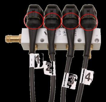


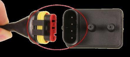


10 Plug and play connections Picture 2n: Interface cable plug Picture 2o: XFP01 Absolute pressure sensor plug Picture 2p: GAS temperature sensor plug Picture 2r: Manometer plug Picture 2s: Reducers temperature sensor plug Picture 2t: GAS injectors plugs 10
 or in liquid phase (LPG) that becomes gaseous at constant pressure at the output.")

11 3. REDUCER installation 3.1. Reducer selection This is an important device located in the engine compartment. It allows the gas to be delivered to injectors at the correct pressure and temperature. Gas is delivered to the reducer as gaseous state (CNG) or in liquid phase (LPG) that becomes gaseous at constant pressure at the output. This device is connected with vehicle cooling system to prevent freezing. It is always necessary to select proper reducer s type according to the power of the engine. Recommendations are given below: LPG: Engine power/type: Reducer s type to be selected: Remarks: up to 200 HP naturally aspirated turbo charged engines up to 300 HP HP naturally aspirated over 300 HP (also turbo charged with such a power) VR-L Standard VR-L SUPER or VR-L LUX VR-L SUPER or VR-L LUX 2xVR-L Standard KIT can be composited with 1-1 type of filters (filter gas flow capacity up to 200 HP) KIT must be composited with two separate 1-1 filters (total gas flow capacity 400 HP). 6 mm internal diameter GAS supply pipe is recommended KIT must be composited with two separate 1-1 filters (total gas flow capacity 400 HP). KIT must be composited with two separate 1-1 filters (total gas flow capacity 400 HP). 6 mm internal diameter GAS supply pipe is required CNG: Engine power/type: Reducer s type to be selected: Remarks: up to 200 HP naturally aspirated turbo charged engines up to 250 HP HP naturally aspirated over 300 HP (also turbo charged with such a power) VR-C VR-C VR-C or 2xVR-C 2xVR-C KIT can be composited with 1-1 type of filters (filter gas flow capacity up to 200 HP) KIT must be composited with two separate 1-1 filters (total gas flow capacity 400 HP) KIT must be composited with two separate 1-1 filters (total gas flow capacity 400 HP). Depends on the instantaneous engine fuel consumption. KIT must be composited with two separate 1-1 filters (total gas flow capacity 400 HP) Practical note: the selection of the regulator s type should always be done taking into consideration some power reserve (the reducer shall always have slightly more power capacity than the engine) Reducer s fitting method The reducer must be stable fitted to fixed elements of the car. It is forbidden to fit the reducer to the engine or any of its components. Picture 3a: Correctly fitter reducer 11
.")
.")
.")


12 Picture 3b: Incorrectly fitter reducer in serial way It is necessary to install water fittings of the reducer in parallel between the engine block and the car heater (see picture 3a). It is forbidden to install water cooling pipes to the reducer in serial that may limit the flow of the engine coolant (see picture 3b). Picture 3c: Incorrectly installed reducer above top level of car cooling system It is necessary to fit the reducer below the highest level of the engine cooling system (picture 3a - correct, 3c - incorrect). The reducer should not be installed in the places where there is too much heat (like exhaust manifold) and should not disturb other engine components service Picture 3d: Correct fitting position - valve coil oriented upward The reducer shall not be installed in places when the surrounding temperature falls during driving and should not be installed as the lowest element in the engine chamber. The reducer shall always be installed with the valve coil oriented upward (see picture 3d). Incorrect fitting position has been marked on the picture no 3e. Picture 3e: Incorrect fitting position- valve coil oriented downward 12
 or Metal o-ring (CNG).")


 It is always")
 CNG (10 mm")


13 Gas inlet connection method: 1. Reducer. 2. Filter set/unit. 3. Inlet nut. 4. Copper o-ring (LPG) or Metal o-ring (CNG). Attention: the o-ring is a disposable part. It is forbidden to use the same o-ring in case the nut was unscrewed once. 5. GAS supply pipe coming from the Tank/container. Picture 3f: Sample reducer connection scheme Practical note: The place of pressure regulator assembly should permit easy access to e.g. change the filter of the liquid phase or pressure regulation. Picture 3g: Gas reducer s outlet hose and its clamp(12-22) It is always recommended to use GAS application dedicated hoses and pipes only. Picture 3h: Cooling liquid hose: LPG (16 mm inside diameter) CNG (10 mm inside diameter) It is recommended to use only original cooling liquid T-fitting for the reducers coolant connection. Picture 3i: Original cooling liquid T-fitting and clamps Adjusting the reducer s pressure Picture 3j: reducer s pressure regulation nozzle Recommended outlet pressure of the reducer should be as follows: VR-L Reducers (LPG): 100 kpa/1bar/14.5 psi (+/- 20%) VR-C reducer (CNG): 160 kpa/1,6 bar/23,2 psi (+/- 20%) Pressure regulation screw of a reducer has been marked on the picture 3j. 13
.")
 with a value higher than the standard provided in the kit - over 10A.")

.")

 Gasoline injectors installation place.")
14 4. FH02 GAS INJECTORS installation Picture 4a: FH02 4-cyl Injector The injectors are electromechanical devices that precisely control the gas supply to be delivered to the engine. Injectors are controlled by the Versus ECU which utilizes signals from variety of vehicle sensors. ECU VERSUS operates properly with several kinds of GAS Injectors (different Brands, impedance). It is essential to choose the type of installed GAS injectors in the software. When choosing the GAS injectors of impedance 1 ohm or lower, it may be necessary to use a fuse (located on the red wire) with a value higher than the standard provided in the kit - over 10A. One injector is used for each cylinder. In case of 4-cyl engine it is possible to use: 1xFH02-4cyl Injector set, 2xFH02-2cyl Injectors set or 4xFHT02-1cyl Injectors set. In case of 6-cyl engine 2xFH02-3cyl Injectors set. Other possibilities are 3xFH02-2cyl or 6xFH02-1cyl. 8-cyl engine 2xFH02-4cyl, 4xFH02-2cyl, 8xFH02-1cyl Inlet manifold nozzles installation Hole diameter for the collector nozzle should be 4.8mm while the screw tap is a typical M6. It is always recommended to remove the inlet manifold from the engine to install the inlet manifold nozzles (filings generated during drilling and tapping can cause engine operation problems). Before dismantling the manifold it is recommended to make signs in place to make holes. After the hole is made and tapped, before fitting the inlet manifold nozzles it is necessary to impose adhesive for threads that will protect them from unscrewing and provide perfect tightness. After cleaning the manifold of the filings, it can be refitted. It is also forbidden to drill accidental holes in the inlet manifold. Picture 4b: Inlet manifold nozzles While installing the inlet manifold nozzles it is essential to follow the rules: Picture 4c: Inlet manifold 1) Gasoline injectors installation place. 2) Ideal place to install GAS inlet manifold nozzles (2-3 cm from gasoline injectors red field) 3) Wrong place of Gas inlet manifold nozzles installation (over 5-6 cm from Gasoline injectors blue field) correct fitting position Picture 4d: incorrect fitting position Inlet manifold nozzles should be installed as close to the petrol injectors in such manner that the injected gas is directed toward the intake valves. 14


15 Picture 4e: Inlet manifold nozzles installed in the same way The holes of gas inlet nozzles need to be drilled the closest to cylinder head. It is essential to keep the same distance and angle for every separate nozzle. Every separate nozzle should be installed in the same way. The nozzle shall be oriented to the central point of inlet manifold channel. Picture 4f: Sample of typical mistake (2 nd cylinder): 1. Inlet manifold nozzle not oriented to the central point of the channel. 2. One inlet manifold nozzle installed in different way than the others When installing the collector nozzles to the engine equipped with a system of variable charge air turbulence (SWIRL, TSCV), be sure to install the nozzles so that at any engine operating mode, the gas can be supplied to the engine smoothly. The presence of turbulence changes can be easily identified by the presence at the end of the inlet manifold (next to the cylinder head) flaps which, by rotation or displacement cause a change of the channel cross-section of the collector. In this case, it is recommended to install the nozzle in such a way that the gas can always flow into the engine. Improper nozzles installation will result in the engine shaking during large load changes that cannot be eliminated by the controller mixture adjustment system. Picture 4g: 1. Inlet manifold flaps (red marked) 2. Correct place of inlet manifold nozzle installation 3. Incorrect place of inlet manifold nozzle installation (air flow limited by flap) 1. Picture 4h: Injector adapters Practical note: TO avoid drilling the holes in inlet manifold it is possible to install the injectors adaptors. For more information please refer to Spare parts catalogue. 15

 according to the formula: Explanations to the formula: The result should be rounded to one decimal")


 must be")

 supporting their fitting that are originally")
16 4.2. GAS injector nozzles size selection Picture 4i: Calibration nozzle diameter Inlet manifold nozzles must be installed in stable way to protect their accidental unscrewing. The calibration nozzles must be sized according to the capacity of the car being converted (engine power and number of cylinders) according to the formula: Explanations to the formula: The result should be rounded to one decimal place. Nozzle size is correct for sequence control and pressure of gas (LPG = 100kPa, CNG = 160kPa). For the semi-sequential or non-sequential types of the engines the nozzle size should be smaller than calculated by about 15%. The size calculated according to this formula shall be treated as general idea of the size. Finally the most optimal size may differ in the range of +/- 15% from the calculated value. Practical note: Picture 4j: Drilling the injectors nozzles In case the size of the calibration nozzle is correctly selected the engine shall smoothly pass the ECU VERSUS system calibration on idle. Finally the software corrections value oscillate in the range between 0,5 2,5 ms. Make sure that the size of all calibration nozzles installed in the car is the same. If size of the nozzles is too small there is a possibility to drill nozzles to make their inner diameter bigger however it is strongly recommended to change their type to bigger ones, originally sized in FHT VERSUSGAS factory. For the sizes available please refer to Spare parts catalogue GAS Injection fitting position Injectors regardless of housing type (single, double, triple, quadruple) must be installed calibration nozzles facing down. Otherwise, despite the applied filters, oily substances will embed that lead to improper operation of the injectors. The injectors must be mounted to a rigid element of the engine that is capable to support them. It is recommended to use the anti-vibration dumpers (picture no 4k) supporting their fitting that are originally supplied with the injector mounting KIT. It is not recommended installing the injectors in a location exposed to cooling down while driving especially in winter. Picture 4k: 1.Anti-vibration dumpers 2.Injectors dumpers fitting place Picture 4l: Correct position of installation Picture 4m: Acceptable position of installation Picture 4n: Incorrect position of installation 16
. Correct installation method is illustrated on Scheme no 3 and Scheme no 4.")


.")
17 Picture 4o: Injectors matched in serial way In case there are (two) 2xFH02 3-cyl Injectors installed it is forbidden to join such a pair of injectors in serial way (see picture 4o). Correct installation method is illustrated on Scheme no 3 and Scheme no 4. In case there are (two) 2xFH02 4-cyl Injectors and two reducers installed: It is also forbidden to join such a pair in serial way. they should be joined together with an additional rubber hose to equalize the pressure between them. For better understanding see Scheme no 5. Picture 4p: FH02 4-cyl Injector installed correctly in the engine chamber Location of the GAS injectors should always strive to minimize the length of the gas supply hoses to the collector nozzles GAS Injectors GAS Inlet manifold Nozzles hoses installation High pressure hose shall be used for connection from injector rail to injector nozzles. Each hose must be secured with tight metal clamps (picture 4q 1 ). It is forbidden to use vacuum connection dedicated clamps for pressure hoses security protection. Picture 4q: Pressure hose clamps used for nozzles connections: 1. Pressure hose clamps AML12 type 2. GAS dedicated hose ø5 mm (nylon inside) Hoses must not be bent or pressed and have to be permeable. 17
.")

 up to 10 cm correct. 3) up to 15 cm acceptable.")
 over 20 cm - forbidden Picture 4s: incorrect length of injection")
18 It should be noted that more important than the length of hoses is their symmetry (all lengths possibly similar). When to maintain of symmetry all the hoses should be extended with a few inches then it should be done. Picture 4r: the length of the hoses 1) up to 5 cm - ideal length. 2) up to 10 cm correct. 3) up to 15 cm acceptable. 4) cm not recommended but allowed. 5) over 20 cm - forbidden Picture 4s: incorrect length of injection hoses hoses too long Picture 4t: incorrect lengths of injection hoses hoses not the same length 18
. 5.")
 Vacuum marked nozzle of the reducer c) Inlet manifold nozzle that must be installed the closest")
 VR Reducer s nozzle b) Inlet manifold")
.")
 chapter 1.2 of this manual b) Scheme no.")

19 5. MAP-SENSOR: vacuum and pressure measurement connection Map-sensor is used to measure gas pressure in the system. It fulfills an additional role which is vacuum measurement in the intake manifold (measurement of engine load) Map-sensor vacuum connection Picture 5a: MAP sensors vacuum Vacuum should be connected to: a) V marked nozzle of map-sensor b) Vacuum marked nozzle of the reducer c) Inlet manifold nozzle that must be installed the closest to the throttle. Description: VACUUM/under-pressure is to be fitted by T-Fitting to: a) VR Reducer s nozzle b) Inlet manifold nozzle c) Vacuum marked nozzle of ECU VERSUS map-sensor Picture 5b: Inlet manifold vacuum fitting nozzle Picture 5c: Reducer s vacuum nozzle The connections should be integrated by using vacuum T-fitting (picture no 5d). Picture 5d: Vacuum T-fitting Detailed connection scheme is illustrated with light green line( ) on: a) Scheme no 1: General scheme of VERSUS system installation (4 cyl. engine sample) chapter 1.2 of this manual b) Scheme no. 5: general connections for 8 cyl. engines over 300 HP chapter no 10 of this manual Picture 5e: Vacuum hose and its dedicated clamp Vacuum dedicated hose (no nylon reinforcement inside picture 5e 2 ) and clamps (picture 5e 1 ) shall be used for vacuum connection. During the installation make sure that the hose is not bent, pressed or obstructed. 19


 outlet nozzle to supply the gas")


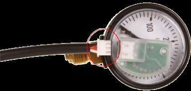
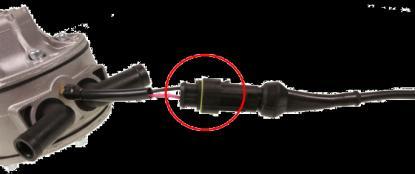
20 5.2. Map-sensor pressure connection Picture 5f: GAS temp. sensor pressure outlet nozzle Picture 5g: Map-sensor pressure nozzle Gas temperature pressure outlet nozzle should be integrated with pressure marked nozzle of mapsensor. High pressure hose shall be used for the connection. The hose must be secured with the dedicated pressure clamps. It is forbidden to use vacuum connection dedicated clamps for pressure hoses security protection. Hoses must not be bent or pressed and have to be permeable. Note: Picture 5h: Gas pressure hose and its dedicated clamp In case of Fh02 1-cyl Injectors it is necessary to use T type of Gas Temperature sensor. In that case the pressure nozzle of map-sensor should be integrated with pressure outlet nozzle of the sensor. There is also a must to use the dedicated filter with 4 (four) outlet nozzle to supply the gas to every injector. In case of the installation with two reducers pressure connection should be made by using T type of Gas temperature sensor as per Scheme no. 5: general connections for 8 cyl. engines over 300 HP chapter no 10.3 of this manual. 6. TEMPERATURE SENSORS Picture 6a: Reducers temperature sensor Reducer s temperature sensor is to be connected to reducer s body. Picture 6b: GAS temperature sensor GAS Temperature sensor should be fitted to GAS Injectors outlet. Practical note: In case of the installation with Filter 1-4 type and the installations with two reducers it is necessary to use T type of the temperature sensors. For more details please see Scheme no 5 and Scheme no 6 (chapter 10.3, 10.4 of this manual) It is recommended to use original ECU VERSUS temperature sensors (others can indicate false temperature and their type need to be selected in the software). 20

.")
 is limited to 200 horsepower.")

 10.2 Scheme no 4: general connections for 6 cyl. engines up to 200-300 HP c) 10.")


21 7. FILTER Picture 7a: Filter 1-1 type Gas filter has an important task of filtering gas impurities and preventing them passing into the injectors which are delicate devices. VERSUS filter is located between Reducer and Injectors. It is very important that the filters are replaced with genuine VERSUS parts at the specified service intervals. The filter is marked with a red arrow indicating the direction of the assembly (in the direction to injectors). Considering the amount of output nozzles there are several types of filters (with one, two, three or four outputs). The gas flow efficiency of one filter (regardless of the number of output nozzles) is limited to 200 horsepower. If the engine power is greater than 200 HP it is necessary to use two filters with Y-fitting. Detailed schemes of filters connections are illustrated in Chapter 10 th of this manual: Picture 7b: T-fitting for filters and filters 1-1 (set for engine over 200 HP) a) 10.1 Scheme no 3: general connections for 6 cyl. engines up to 200 HP b) 10.2 Scheme no 4: general connections for 6 cyl. engines up to HP c) 10.3 Scheme no 5: general connections for 8 cyl. engines over 300 HP d) 10.4 Scheme no 6: general connections for 4 cyl engines with FH02 1-cyl injectors It is forbidden to use a single filter with regulators in versions SUPER, LUX, VR-C in plants above 200 HP. Such use may cause a drop in gas pressure flow through the filter. Picture 7c: Forbidden connection method: SUPER reducer (300 HP) and one filter (200 HP) Picture 7d: Gas dedicated hose and clamp Only gas dedicated hoses and high pressure clamps shall be used in the filter connection. 21


 There is a possibility to turn the")


22 8. GAS LEVEL SENSORS installation 8.1. LPG VERSUS 1050 LPG Level sensor installation Picture 8a: VERSUS LPG level sensor 1050 type The sensor s wiring should be connected according to the scheme (picture no 8b) The sensor itself should be fitted to the Multivalve (see picture no 8c) There is a possibility to turn the indicator left or right in order to achieve adequate LPG Level indication on the Switch (If LPG Tank is full all diodes should shine). Picture 8b: VERSUS LPG level sensor 1050 type installation scheme Picture 8c: VERSUS LPG level sensor 1050 type already fitted 8.2. CNG VERSUS VR-C 01 manometer installation CNG VERSUS VR-C 01 Level indicator: Picture 8d: CNGVERSUS VR-C 01 level indicator correct fitting method The role of the manometer is to measure the pressure of the CNG tank. The results of this measurement are displayed on the switch assembled in the cab. Manometer should be connected to the T-fitting with metal nuts. Also, metal O-ring should be used to seal the connections. It is forbidden to screw the manometer by grabbing its cover with a wrench (picture 8f). 1) Metal nut 2) Metal o-ring 3) T-fitting 4) Aluminum seal 5) VR-C 01 sensor/manometer Picture 8e: VR-C 01 fitting scheme Picture 8f: Incorrect fitting method 22


23 9. CHANGE OVER SWITCH display modes and buzzer installation The switch allows to select the type of the fuel: Gasoline or gas. The switching from one fuel to another can be done by pressing the switch button. Both the switch and the buzzer shall be installed in the driver s cabin Switch signaling modes Picture 9a: GASOLINE mode display GASOLINE mode no diodes shining in the switch (picture 9a): Gasoline fuel is supplied to the engine. When the switch button is pressed the controller switches to AUTO mode. AUTO mode all diodes flashing in the switch (picture 9b): Picture 9b: AUTO mode display Gasoline fuel is supplied to the engine, however ECU VERSUS system is ready to switch the fuel to GAS in case switching conditions are met (RPM level, temperature, delay level). As soon as the conditions are met ECU VERSUS switches the fuel to GAS automatically. When switch button is pressed the controllers switches to GASOLINE mode again. GAS mode diodes are shining constantly (picture 9c): GAS fuel is supplied to the engine The amount of GAS in the tank is displayed on the switch (picture 9c) When switch button is pressed the controller switches to GASOLINE mode. EMPTY Tank mode diodes light up one after the other (picture 9d): Picture 9d: EMPTY Tank mode display the mode activated only when there is no GAS pressure recognized by the system. Gasoline fuel is supplied to the engine. As soon as the system recognize that the Tank was filled over 50% - the controller switches automatically to AUTO mode after 1-3 minutes. In case the Tank was filled less than 50%, switch button needs to be pressed to switch to AUTO mode. Pressing the switch button change the mode to AUTO. EMERGENCY mode start the engine with GAS fuel: Picture 9c: GAS mode display 5 types of display possible depending on the Gas level in the tank in %: 100% 75% 50% 25% reserve There is a possibility to start the engine with GAS without using GASOLINE in emergency mode, however it is recommended only in emergency situations. Procedure: Press and hold pressed the switch button Start the engine when the button is pressed The engine is supplied with GAS, and the ECU VERSUS controller switches to GAS mode directly with no delay. CALIBRATION mode top diode blinking and some other diodes shining (picture 9e): Picture 9e: CALIBRATION mode display For more information see Fully-automatic mapping chapter of the software manual. 23


, the controller completes the procedure that is confirmed with: - Two top diodes shining for 3 seconds and - One beep signal can be")
 Test negative leakage detected: If within 15 seconds, the controller registers a pressure decrease of more than 15kPa the controller completes the procedure that is confirmed with: - Two bottom")


24 9.2. Leak test procedure steps 1. The engine should be started, working with gasoline ( AUTO mode with the diodes blinking or GASOLINE mode with no diodes shining/blinking) 2. Press and hold the switch button for about 10sec. 3. After this time one beep signal can be heard and the switch start to indicate the process of testing with two extreme diodes blinking (see picture 9g). 4. Release the button and wait for calibration end. A) AUTO mode Picture no 9f: Leakage test start from B) GASOLINE mode Scenarios: Picture no 9g: leakage test in progress a) Test positive no leakage: For the next 15 seconds measurement of pressure is made and if there is no drop of the pressure (there is not a leak), the controller completes the procedure that is confirmed with: - Two top diodes shining for 3 seconds and - One beep signal can be heard After this time the controller switches the mode to AUTO mode. b) Test negative leakage detected: If within 15 seconds, the controller registers a pressure decrease of more than 15kPa the controller completes the procedure that is confirmed with: - Two bottom diodes shining for 3 seconds and - Triple beep signal can be heard After this time the controller switches the mode to Gasoline mode. Picture no 9h: leakage test positive Picture no 9i: leakage test negative Notes: - In case a tank is empty, the leakage test will never be performed correctly, the result will be negative. Please make sure that the tank is at least ¼ filled. - Please note that this procedure can only check for leakage of the output section of the regulator, gas hose with filter, injection rail and Pressure sensor/map-sensor. Other leaks are not detected. - The efficiency of the procedure also depends strongly on the type of regulator (solenoid valve must be attached close to the regulator). In case the solenoid valve is located far away from the regulator and there is a pipe full of gas between the devices, the potential pressure falls of the evaporated gas pressure will be compensated by GAS coming from this intermediate pipe. In such special cases (gas solenoid away from the regulator), medium and small leaks are not being detected. - It is unacceptable to check the leaks just by using the above procedure. Leak test always must include all pressure connections with use appropriate leak testers Buzzer installation and signalization Picture no 9j: Buzzer security label to be removed The buzzer should be installed in the driver s cabin. After the device installation make sure the security label is taken off. Horn signals always indicated: EMPTY tank mode beginning 3 beep signals More signaling modes has been widely described in the software manual. 24


25 10. OTHER SCHEMES Scheme no 3: general connections for 6 cyl. engines up to 200 HP LEGEND: Liquid gas supply line - Evaporated Gas supply line - Vacuum connection - Coolant connection scheme - 1. VR-L Standard reducer 2. Filter Gas Temperature Sensor 4. FH02 3-cyl Injectors 5. MAP-sensor XFP01 type 25

26 10.2. Scheme no 4: general connections for 6 cyl. Engines HP LEGEND: Liquid gas supply line - Evaporated Gas supply line - Vacuum connection - Coolant connection scheme - 1. VR-L SUPER reducer 2. T-fitting for filters 3. Filters Gas Temperature Sensor 5. FH02 3-cyl Injectors 6. MAP-sensor XFP01 type 26


27 10.3. Scheme no 5: general connections for 8 cyl. engines over 300 HP LEGEND: Liquid gas supply line Evaporated gas supply line Vacuum connection Coolant connection scheme 1. VR-L Standard reducers 2. Filters Gas Temperature Sensor 4. FH02 4-cyl Injectors 5. MAP-sensor XFP01 type 6. Vacuum T-fittings 7. Gas pressure equalization hose 27


28 10.4. Scheme no 6: general connections for 4 cyl. engines with FH02 1-cyl injectors LEGEND: Liquid gas supply line - Evaporated Gas supply line - Vacuum connection - Coolant connection scheme - 1. VR-L Standard reducer 2. Filter Gas Temperature Sensor T type 4. FH02 1-cyl Injectors 5. MAP-sensor XFP01 type For more advanced technical explanations please visit restricted area of our website: Thanks for studying the manual to the end! The pictures, text description, nameplates, technical data that is contained in this manual are the property of FHT VERSUSGAS. Copying of this property without FHT VERSUSGAS prior written permission is prohibited. 28
VERSUS GAS USA 1/1/2013
 GRATEC: ALTERNATIVE FUELS DIVISION INSTALLATION MANUAL VERSUS GAS Premium Sequential Systems VERSUS GAS USA 1/1/2013 This manual will guide you step by step through the installation process of your new
VERSUS GAS USA 1/1/2013
 GRATEC: ALTERNATIVE FUELS DIVISION USER S MANUAL VERSUS GAS Premium Sequential Systems VERSUS GAS USA 1/1/2013 This manual describes all possible scenarios the user may face as well as the safe operation
Instruction of connection and programming of the OSCAR-N controller
 Instruction of connection and programming of the OSCAR-N controller Table of content Paragraph Description Page 1 Installation of OSCAR-N sequential gas injection system 2 1.1 OSCAR-N sequential gas injection
EG DYNAMIC user manual
 Timing Advance Processor EG DYNAMIC user manual ver. 1.1.0 dated 2012-10-01 This instruction can be also downloaded from: http://www.europegas.pl/en/technical-support/service-manuals Latest software version
MAKE OF AUTOMOBILE: ENGINE SET NUMBER 345/ NUMBER : 076/ DATE : VERSION NR : B
 MAKE OF AUTOMOBILE: TYPE: LOGAN PISTON DISPLACEMENT: 1600 NUMBER OF VALVES: 8 ENGINE NUMBER: K7M 710 TRANSMISSION TYPE ( MT / AT ) MT VEHICLE CATEGORIES M or N ( M ) TYPE VSI INJECTOR ( NUMBER + COLOR
Preparing and programming of ESGI 2 LPG supply system manual
 Preparing and programming of ESGI 2 LPG supply system manual Part II Instruction of preparing and programming the ESGI system 1 Technical data of the central unit Vs Power supply voltage 0...16V V i_an
MAKE OF AUTOMOBILE: MODEL YEAR: 2007 SYSTEM APPROVAL NUMBER ( R115 ) VSI-LPG 10 ENGINE SET NUMBER 364/
 VSI-LPG 10 ENGINE SET NUMBER 364/") MAKE OF AUTOMOBILE: TYPE: FABIA PISTON DISPLACEMENT: 1400 NUMBER OF VALVES: 16 ENGINE NUMBER: BUD TRANSMISSION TYPE ( MT / AT ) MT VEHICLE CATEGORIES M or N M TYPE VSI INJECTOR ( NUMBER + COLOR ) 180/30410
MAKE OF AUTOMOBILE: TYPE: FABIA PISTON DISPLACEMENT: 1400 NUMBER OF VALVES: 16 ENGINE NUMBER: BUD TRANSMISSION TYPE ( MT / AT ) MT VEHICLE CATEGORIES M or N M TYPE VSI INJECTOR ( NUMBER + COLOR ) 180/30410
MAKE OF AUTOMOBILE: ENGINE SET NUMBER 366/
 MAKE OF AUTOMOBILE: TYPE: SORENTO PISTON DISPLACEMENT: 3300 NUMBER OF VALVES: 24 ENGINE NUMBER: G6DB TRANSMISSION TYPE ( MT / AT ) MT VEHICLE CATEGORIES M or N M TYPE VSI INJECTOR ( NUMBER + COLOR ) 180/30340
MAKE OF AUTOMOBILE: TYPE: V 70 PISTON DISPLACEMENT: 2521 NUMBER OF VALVES:
 MAKE OF AUTOMOBILE: TYPE: V 70 PISTON DISPLACEMENT: 2521 NUMBER OF VALVES: 20V ENGINE NUMBER: B5254T TRANSMISSION TYPE ( MT / AT ) AT VEHICLE CATEGORIES M or N PASSENGER CAR ( M ) TYPE VSI INJECTOR (COLOUR
MAKE OF AUTOMOBILE: PISTON DISPLACEMENT: 8300 NUMBER OF VALVES: 20 TRANSMISSION TYPE ( MT / AT ) TYPE VSI INJECTOR (COLOR ) VERSION ( LPG / CNG )
 TYPE VSI INJECTOR (COLOR ) VERSION ( LPG / CNG )") MAKE OF AUTOMOBILE: TYPE: PISTON DISPLACEMENT: 8300 NUMBER OF VALVES: 20 ENGINE NUMBER: SRT V10 Viper TRANSMISSION TYPE ( MT / AT ) AT TYPE VSI INJECTOR (COLOR ) YELLOW VERSION ( LPG / CNG ) LPG INJECTION
MAKE OF AUTOMOBILE: TYPE: PISTON DISPLACEMENT: 8300 NUMBER OF VALVES: 20 ENGINE NUMBER: SRT V10 Viper TRANSMISSION TYPE ( MT / AT ) AT TYPE VSI INJECTOR (COLOR ) YELLOW VERSION ( LPG / CNG ) LPG INJECTION
Instruction of connection and programming of the VECTOR controller
 Instruction of connection and programming of the VECTOR controller 1. Connection of wiring 1.1.VECTOR Connection diagram Fig. 1 VECTOR Diagram of connection to the vehicle wiring. 1.2.Connection of wiring
MAKE OF AUTOMOBILE: PISTON DISPLACEMENT: 1300
 MAKE OF AUTOMOBILE: TYPE: YARIS PISTON DISPLACEMENT: 1300 NUMBER OF VALVES: 16 VVT-I ENGINE NUMBER: 2SZ-FE TRANSMISSION TYPE ( MT / AT ) AT VEHICLE CATEGORIES M or N M TYPE VSI INJECTOR ( NUMBER + COLOR
Installation And Programming Manual of OPTIMA Eco Tec and OPTIMA Pro Tec OBD/CAN
 v1.03 [EN] Installation And Programming Manual of OPTIMA Eco Tec and OPTIMA Pro Tec OBD/CAN ALEX Zambrowska 4A, 16-001 Kleosin Poland tel./fax: +48 85 664 84 40 www.optimagas.pl e-mail: service@optimagas.pl
MAKE OF AUTOMOBILE: MODEL YEAR: 2004 SYSTEM APPROVAL NUMBER ( R115 ) ENGINE SET NUMBER 336/
 ENGINE SET NUMBER 336/") MAKE OF AUTOMOBILE: TYPE: A4 PISTON DISPLACEMENT: 1800 NUMBER OF VALVES: 20V ENGINE NUMBER: BFB TRANSMISSION TYPE ( MT / AT ) AT VEHICLE CATEGORIES M or N M TYPE VSI INJECTOR ( NUMBER + COLOR ) YELLOW
MAKE OF AUTOMOBILE: TYPE: A4 PISTON DISPLACEMENT: 1800 NUMBER OF VALVES: 20V ENGINE NUMBER: BFB TRANSMISSION TYPE ( MT / AT ) AT VEHICLE CATEGORIES M or N M TYPE VSI INJECTOR ( NUMBER + COLOR ) YELLOW
MODEL YEAR: SYSTEM APPROVAL NUMBER ( R115 ) R ENGINE SET NUMBER 354/
 R ENGINE SET NUMBER 354/") MAKE OF AUTOMOBILE: MERECEDES TYPE: E200 W211 PISTON DISPLACEMENT: 1796 NUMBER OF VALVES: 16 ENGINE NUMBER: M271 TRANSMISSION TYPE ( MT / AT ) AT VEHICLE CATEGORIES M or N M TYPE VSI INJECTOR ( NUMBER
MAKE OF AUTOMOBILE: MERECEDES TYPE: E200 W211 PISTON DISPLACEMENT: 1796 NUMBER OF VALVES: 16 ENGINE NUMBER: M271 TRANSMISSION TYPE ( MT / AT ) AT VEHICLE CATEGORIES M or N M TYPE VSI INJECTOR ( NUMBER
MODEL YEAR: 2007 SYSTEM APPROVAL NUMBER ( R115 ) R ENGINE SET NUMBER 350/
 R ENGINE SET NUMBER 350/") MAKE OF AUTOMOBILE: TYPE: KALINA 1117/ 1118 / 1119 PISTON DISPLACEMENT: 1600 NUMBER OF VALVES: 8 ENGINE NUMBER: 21114 TRANSMISSION TYPE ( MT / AT ) MT VEHICLE CATEGORIES M or N M TYPE VSI INJECTOR ( NUMBER
MAKE OF AUTOMOBILE: TYPE: KALINA 1117/ 1118 / 1119 PISTON DISPLACEMENT: 1600 NUMBER OF VALVES: 8 ENGINE NUMBER: 21114 TRANSMISSION TYPE ( MT / AT ) MT VEHICLE CATEGORIES M or N M TYPE VSI INJECTOR ( NUMBER
MODEL YEAR: 2009 SYSTEM APPROVAL NUMBER ( R115 ) R ENGINE SET NUMBER 350/
 R ENGINE SET NUMBER 350/") MAKE OF AUTOMOBILE: TYPE: PRIORA 2170 / 2172 PISTON DISPLACEMENT: 1600 NUMBER OF VALVES: 16 ENGINE NUMBER: 21126 TRANSMISSION TYPE ( MT / AT ) MT VEHICLE CATEGORIES M or N M TYPE VSI INJECTOR (COLOR )
MAKE OF AUTOMOBILE: TYPE: PRIORA 2170 / 2172 PISTON DISPLACEMENT: 1600 NUMBER OF VALVES: 16 ENGINE NUMBER: 21126 TRANSMISSION TYPE ( MT / AT ) MT VEHICLE CATEGORIES M or N M TYPE VSI INJECTOR (COLOR )
MAKE OF AUTOMOBILE: PISTON DISPLACEMENT: 2700 NUMBER OF VALVES:
 MAKE OF AUTOMOBILE: DODGE TYPE: JOURNEY PISTON DISPLACEMENT: 2700 NUMBER OF VALVES: 24V ENGINE NUMBER: 2.7V6 EER TRANSMISSION TYPE ( MT / AT ) AT VEHICLE CATEGORIES M or N M TYPE VSI INJECTOR ( COLOR )
MAKE OF AUTOMOBILE: PISTON DISPLACEMENT: 1600 NUMBER OF VALVES: 16
 MAKE OF AUTOMOBILE: TYPE: MERIVA PISTON DISPLACEMENT: 1600 NUMBER OF VALVES: 16 ENGINE NUMBER: Z16XEP TRANSMISSION TYPE ( MT / AT ) MT VEHICLE TYPE M TYPE VSI INJECTOR ( NUMBER + COLOR ) 180/30430 ORANGE
MANUFACTURER TYPE F-150 ENGINE DISPLACEMENT NUMBER OF VALVES FIRING ORDER VEHICLE CATEGORIES TRANSMISSION
 MANUFACTURER Ford TYPE F-150 ENGINE DISPLACEMENT 3500cc NUMBER OF VALVES 24v ENGINE CODE / NUMBER - OUTPUT 3.5L EcoBoost 2015 365hp FIRING ORDER 1-4-2-5-3-6 VEHICLE CATEGORIES M TRANSMISSION AT VERSION
MAKE OF AUTOMOBILE: 316 / 318i E46 NUMBER OF VALVES:
 MAKE OF AUTOMOBILE: TYPE: 316 / 318i E46 PISTON DISPLACEMENT: 1800 2000 cc NUMBER OF VALVES: 16V ENGINE NUMBER: N42B18A / N42B20A TRANSMISSION TYPE ( MT / AT ) MT VEHICLE CATEGORIES M or N M TYPE VSI INJECTOR
MAKE OF AUTOMOBILE: GRAND CHEROKEE PISTON DISPLACEMENT: 5700 NUMBER OF VALVES: 16
 MAKE OF AUTOMOBILE: TYPE: GRAND CHEROKEE PISTON DISPLACEMENT: 5700 NUMBER OF VALVES: 16 ENGINE NUMBER: 5.7V8 HEMI TRANSMISSION TYPE ( MT / AT ) AT VEHICLE CATEGORIES M or N M TYPE VSI INJECTOR ( NUMBER
MAKE OF AUTOMOBILE: ENGINE SET NUMBER 337/
 MAKE OF AUTOMOBILE: TYPE: NITRO PISTON DISPLACEMENT: 3700 NUMBER OF VALVES: 12V ENGINE NUMBER: V6 TRANSMISSION TYPE ( MT / AT ) AT VEHICLE CATEGORIES M or N M TYPE VSI INJECTOR ( NUMBER + COLOR ) 180/30330
Prins autogassystemen b.v. Veldhoven
 Prins autogassystemen b.v. Veldhoven MOUNTING INSTRUCTION ENGINE CONVERSION SET MAKE OF AUTOMOBILE: TYPE: ASTRA PISTON DISPLACEMENT: 2000 cc MT NUMBER OF VALVES: 16V ENGINE NUMBER: X20XEV INJECTION SYSTEM:
MAKE OF AUTOMOBILE: PISTON DISPLACEMENT: NUMBER OF VALVES: ENGINE NUMBER: TRANSMISSION TYPE ( MT / AT ) VEHICLE CATEGORIES M or N PERSONEN AUTO ( M )
 VEHICLE CATEGORIES M or N PERSONEN AUTO ( M )") MAKE OF AUTOMOBILE: TYPE: WRANGLER PISTON DISPLACEMENT: 4000 cc NUMBER OF VALVES: 12 v ENGINE NUMBER: M3 TJ TRANSMISSION TYPE ( MT / AT ) MT VEHICLE CATEGORIES M or N PERSONEN AUTO ( M ) TYPE VSI INJECTOR
MAKE OF AUTOMOBILE: TYPE: WRANGLER PISTON DISPLACEMENT: 4000 cc NUMBER OF VALVES: 12 v ENGINE NUMBER: M3 TJ TRANSMISSION TYPE ( MT / AT ) MT VEHICLE CATEGORIES M or N PERSONEN AUTO ( M ) TYPE VSI INJECTOR
MANUFACTURER Explorer Sport ENGINE DISPLACEMENT NUMBER OF VALVES FIRING ORDER VEHICLE CATEGORIES TRANSMISSION
 MANUFACTURER Ford TYPE Explorer Sport ENGINE DISPLACEMENT 3500cc NUMBER OF VALVES 24v ENGINE CODE / NUMBER 3.5L GTDi Ecoboost FIRING ORDER 1 4 2 5-3 - 6 VEHICLE CATEGORIES M TRANSMISSION AT VERSION AFC-2.1
Technical Installation Guide
 Technical Installation Guide ID Technical Document: DT_IS_GAI-005 Rev. Date Review n. Issued by Reviewed/ Approved 0 13/04/2007 First Issue Technical office ROS 1 19/02/2009 Second Issue Technical office
MAKE OF AUTOMOBILE: ENGINE SET NUMBER 348/
 MAKE OF AUTOMOBILE: TYPE: CIVIC PISTON DISPLACEMENT: 1800 NUMBER OF VALVES: 16 ENGINE NUMBER: R18A TRANSMISSION TYPE ( MT / AT ) MT VEHICLE CATEGORIES M or N M TYPE VSI INJECTOR ( COLOR ) ORANGE VERSION
MODEL YEAR: 2010 SYSTEM APPROVAL NUMBER ( R115 ) R ENGINE SET NUMBER 349/ (.06 /.07 )
 R ENGINE SET NUMBER 349/ (.06 /.07 )") MAKE OF AUTOMOBILE: TYPE: IX35 PISTON DISPLACEMENT: 2000 NUMBER OF VALVES: 16 ENGINE NUMBER: G4KD TRANSMISSION TYPE ( MT / AT ) MT VEHICLE CATEGORIES M or N M TYPE VSI INJECTOR ( COLOUR ) Orange VERSION
MAKE OF AUTOMOBILE: TYPE: IX35 PISTON DISPLACEMENT: 2000 NUMBER OF VALVES: 16 ENGINE NUMBER: G4KD TRANSMISSION TYPE ( MT / AT ) MT VEHICLE CATEGORIES M or N M TYPE VSI INJECTOR ( COLOUR ) Orange VERSION
PISTON DISPLACEMENT: NUMBER OF VALVES: 16. TRANSMISSION TYPE ( MT / AT ) VEHICLE CATEGORIES M or N TYPE VSI INJECTOR ( COLOUR ) VERSION ( LPG / CNG )
 VEHICLE CATEGORIES M or N TYPE VSI INJECTOR ( COLOUR ) VERSION ( LPG / CNG )") MAKE OF AUTOMOBILE: TYPE: Ram PISTON DISPLACEMENT: 5700cc NUMBER OF VALVES: 16 ENGINE NUMBER: 5.7V8 Hemi 290kW TRANSMISSION TYPE ( MT / AT ) AT VEHICLE CATEGORIES M or N M TYPE VSI INJECTOR ( COLOUR )
MAKE OF AUTOMOBILE: TYPE: Ram PISTON DISPLACEMENT: 5700cc NUMBER OF VALVES: 16 ENGINE NUMBER: 5.7V8 Hemi 290kW TRANSMISSION TYPE ( MT / AT ) AT VEHICLE CATEGORIES M or N M TYPE VSI INJECTOR ( COLOUR )
MAKE OF AUTOMOBILE: MODEL YEAR: 2007 SYSTEM APPROVAL NUMBER ( R115 ) R ENGINE SET NUMBER 349/
 R ENGINE SET NUMBER 349/") MAKE OF AUTOMOBILE: KIA TYPE: CARENS PISTON DISPLACEMENT: 2000 NUMBER OF VALVES: 16 ENGINE NUMBER: G4KA TRANSMISSION TYPE ( MT / AT ) MT VEHICLE CATEGORIES M or N M TYPE VSI INJECTOR ( COLOUR ) ORANGE
MAKE OF AUTOMOBILE: KIA TYPE: CARENS PISTON DISPLACEMENT: 2000 NUMBER OF VALVES: 16 ENGINE NUMBER: G4KA TRANSMISSION TYPE ( MT / AT ) MT VEHICLE CATEGORIES M or N M TYPE VSI INJECTOR ( COLOUR ) ORANGE
Using the Gratec Gasoline software
 Using the Gratec Gasoline software The Gratec Software is a sophisticated yet user friendly program in which configures the Gratec CNG or LPG system to perform with your vehicle. Software version 2.002
PISTON DISPLACEMENT: 1200 NUMBER OF VALVES: ENGINE NUMBER: TRANSMISSION TYPE ( MT / AT ) VEHICLE CATEGORIES M or N TYPE VSI INJECTOR (COLOUR )
 VEHICLE CATEGORIES M or N TYPE VSI INJECTOR (COLOUR )") MAKE OF AUTOMOBILE: VOLKSWAGEN TYPE: POLO PISTON DISPLACEMENT: 1200 NUMBER OF VALVES: 8V ENGINE NUMBER: BZG TRANSMISSION TYPE ( MT / AT ) MT VEHICLE CATEGORIES M or N M TYPE VSI INJECTOR (COLOUR ) BLUE
MAKE OF AUTOMOBILE: VOLKSWAGEN TYPE: POLO PISTON DISPLACEMENT: 1200 NUMBER OF VALVES: 8V ENGINE NUMBER: BZG TRANSMISSION TYPE ( MT / AT ) MT VEHICLE CATEGORIES M or N M TYPE VSI INJECTOR (COLOUR ) BLUE
MAKE OF AUTOMOBILE: TYPE: 508 PISTON DISPLACEMENT: NUMBER OF VALVES: FIRING ORDER: TRANSMISSION TYPE ( MT / AT ) VEHICLE CATEGORIES M or N
 VEHICLE CATEGORIES M or N") MAKE OF AUTOMOBILE: Peugeot TYPE: 508 PISTON DISPLACEMENT: 1600cc NUMBER OF VALVES: 16v ENGINE NUMBER: EP6CDT 115kW FIRING ORDER: 1-3-4-2 TRANSMISSION TYPE ( MT / AT ) MT VEHICLE CATEGORIES M or N M TYPE
MAKE OF AUTOMOBILE: Peugeot TYPE: 508 PISTON DISPLACEMENT: 1600cc NUMBER OF VALVES: 16v ENGINE NUMBER: EP6CDT 115kW FIRING ORDER: 1-3-4-2 TRANSMISSION TYPE ( MT / AT ) MT VEHICLE CATEGORIES M or N M TYPE
Megasquirt EX, Installation Instructions document revision 1.4 (Includes also the version equipped with wasted-spark ignition)
") Megasquirt EX, Installation Instructions document revision 1.4 (Includes also the version equipped with wasted-spark ignition) General Megasquirt EX is a programmable engine control system, based on Megasquirt
Megasquirt EX, Installation Instructions document revision 1.4 (Includes also the version equipped with wasted-spark ignition) General Megasquirt EX is a programmable engine control system, based on Megasquirt
ENGINE DISPLACEMENT NUMBER OF VALVES 16 VEHICLE CATEGORIES
 MANUFACTURER Dacia TYPE Duster ENGINE DISPLACEMENT 1200cc NUMBER OF VALVES 16 ENGINE CODE / NUMBER H5F (TCe125) VEHICLE CATEGORIES M TRANSMISSION MT (6-speed) VERSION AFC-2.1 PETROL ECU MANUFACTURER /
ENGINE DISPLACEMENT 2000 NUMBER OF VALVES 16 ENGINE SET NUMBER
 MANUFACTURER Subaru TYPE Forester ENGINE DISPLACEMENT 2000 NUMBER OF VALVES 16 ENGINE CODE / NUMBER FA20 DIT VEHICLE CATEGORIES M TRANSMISSION AT VERSION Direct LiquiMax-2.1 PETROL ECU MANUFACTURER / CODE
Instruction of connection and programming of the OSCAR-N MINI controller
 Instruction of connection and programming of the OSCAR-N MINI controller Table of content Paragraph Description Page Introduction 2 1 Installation of OSCAR-N MINI sequential gas injection system 4 1.1
Megane Estate ENGINE DISPLACEMENT NUMBER OF VALVES VEHICLE CATEGORIES
 MANUFACTURER Renault TYPE Megane Estate ENGINE DISPLACEMENT 1200cc NUMBER OF VALVES 16v ENGINE CODE / NUMBER H5F (TCe115) VEHICLE CATEGORIES M TRANSMISSION MT(6) VERSION AFC-2.1 PETROL ECU MANUFACTURER
Installation Instructions General Motors 8.1 Sequential Vapor Injection (S.V.I.) System 7500/6500 Series Trucks model year.
 System 7500/6500 Series Trucks model year.") Installation Instructions General Motors 8.1 Sequential Vapor Injection (S.V.I.) System 7500/6500 Series Trucks 2003-2005 model year. Technocarb Equipment (2004) Ltd. 4-30435 Progressive Way Abbotsford,
Installation Instructions General Motors 8.1 Sequential Vapor Injection (S.V.I.) System 7500/6500 Series Trucks 2003-2005 model year. Technocarb Equipment (2004) Ltd. 4-30435 Progressive Way Abbotsford,
INDEX 1 Introduction 2- Software installation 3 Open the program 4 General - F2 5 Configuration - F3 6 - Calibration - F5 7 Model - F6 8 - Map - F7
 SET UP MANUAL INDEX 1 Introduction 1.1 Features of the Software 2- Software installation 3 Open the program 3.1 Language 3.2 Connection 4 General - F2 4.1 The sub-folder Error visualization 5 Configuration
Fitting Instructions: Street Triple from VIN and Street Triple R from VIN A
 English Fitting Instructions: Street Triple from VIN 560477 and Street Triple R from VIN 560477 A9808113 Thank you for choosing this Triumph genuine accessory kit. This accessory kit is the product of
MAKE OF AUTOMOBILE: NUMBER : 076/ DATE : Copyright Prins Autogassystemen B.V VERSION NR : B
 MAKE OF AUTOMOBILE: Ford TYPE: Mondeo PISTON DISPLACEMENT: 2000 NUMBER OF VALVES: 16 ENGINE NUMBER: AOBA TYPE VSI INJECTOR ( COLOR ) Yellow MODEL YEAR: 2010 ENGINE SET NUMBER 347/1810500.07 NUMBER : 076/0703201
ENGINE DISPLACEMENT NUMBER OF VALVES ENGINE SET NUMBER VEHICLE CATEGORIES. Direct LiquiMax-2.0 PETROL ECU MANUFACTURER / CODE Bosch MED 17.
 MANUFACTURER VOLVO TYPE V60 / V70 T4F ENGINE DISPLACEMENT 1600cc NUMBER OF VALVES 16v ENGINE CODE / NUMBER B4164T2 VEHICLE CATEGORIES M TRANSMISSION MT/AT VERSION Direct LiquiMax-2.0 PETROL ECU MANUFACTURER
Romano Injection System 01/11/2013 Rev. 0
 Romano Injection System E 01/11/2013 Rev. 0 Romano Injection System E Romano ECU E is the last generation phased sequential system designed by Romano Srl. This system is the result of the research and
English. Fitting Instructions: Trophy and Trophy SE A of 12. Parts Supplied:
 English Fitting Instructions: Trophy and Trophy SE A9808015 Thank you for choosing this Triumph genuine accessory kit. This accessory kit is the product of Triumph's use of proven engineering, exhaustive
MULTIPOINT FUEL INJECTION (MPI) <4G9>
 <4G9>") MULTIPOINT FUEL INJECTION (MPI) 13C-1 MULTIPOINT FUEL INJECTION (MPI) CONTENTS GENERAL................................. 2 Outline of Changes............................ 2 GENERAL INFORMATION...................
MULTIPOINT FUEL INJECTION (MPI) 13C-1 MULTIPOINT FUEL INJECTION (MPI) CONTENTS GENERAL................................. 2 Outline of Changes............................ 2 GENERAL INFORMATION...................
Installation & Operation manual
 Installation & Operation manual TESA Electronic and special devices - via Etiopia 7-65015 Montesilvano PE - ITALY Tel. (0039) 085 4175602 info@tesaitaly.com www.tesaitaly.com Distributed in the U.K. by
SEQUENT 56: MULTIPOINT SEQUENTIAL INJECTION SYSTEM FOR CYLINDER VEHICLES FIELD OF APPLICATION
 SEQUENT 56: MULTIPOINT SEQUENTIAL INJECTION SYSTEM FOR 5-6-8 CYLINDER VEHICLES FIELD OF APPLICATION Sequent 56 is the evolution of the multipoint injection system for LPG by BRC. New concept product, Sequent
LAMBDA SENSOR CONTROLLER
 LAMBDA SENSOR CONTROLLER INSTALLATION & PROGRAMMING MANUAL version : V1.77 -V1.79 Manufacturer: AC Spółka Akcyjna. 15-182 Białystok, ul. 27 Lipca 64, Poland tel. +48 85 7438148, fax +48 85 653 8649 www.ac.com.pl,
Error codes Diagnostic plug Read-out Reset Signal Error codes
 Error codes Diagnostic plug Diagnostic plug: 1 = Datalink LED tester (FEN) 3 = activation error codes (TEN) 4 = positive battery terminal (+B) 5 = ground Read-out -Connect LED tester to positive battery
Fuel injection system, servicing
 24-1 Fuel injection system, servicing Component locations overview 1 - Oxygen sensor 1 before Three Way Catalyst G39 2 - Oxygen sensor 2 after Three Way Catalyst G130 3 - Engine Coolant Temperature sensor
INSTRUCTIONS & MANUAL FOR THE AUTOGAS ECU. MA-V4 MA-V4mini MA-X6 MA-X8
 INSTRUCTIONS & MANUAL FOR THE AUTOGAS ECU MA-V4 MA-V4mini MA-X6 MA-X8 TABLE OF CONTENTS 1. Connection of MA-V4 2. The program features description 2.1 The indicators 2.2 Settings 2.3 Advanced 3. Calibration
M.T.M. s.r.l. Via La Morra, Cherasco (Cn) - Italy Tel Fax
 - Italy Tel Fax") M.T.M. s.r.l. Via La Morra, 06 - Cherasco (Cn) - Italy Tel. +9 07 486040 Fax +9 07 4887 installation handbook - / installation typologies - / software handbook - / Sequent fastness with and Zenith reducer
M.T.M. s.r.l. Via La Morra, 06 - Cherasco (Cn) - Italy Tel. +9 07 486040 Fax +9 07 4887 installation handbook - / installation typologies - / software handbook - / Sequent fastness with and Zenith reducer
Specialist Components. SPi 5 Port EFI Kit
 Specialist Components SPi 5 Port EFI Kit Version 1.1 Sept 2012 Congratulations on the purchase of your SPi 5 port EFI Kit! Kit Content:- Alloy inlet manifold gasflowed to suit 45/50mm throttle body Injector
GENERAL MOTORS SERVICE PARTS OPERATION 6200 Grand Pointe Drive, Grand Blanc, MI 48439
 LS IGNITION CONTROLLER 19355418 Ignition Control for Carbureted LS Series Engines (24x Crankshaft Index/1x Camshaft Index, 58x Crankshaft Index/4x Camshaft Index) Parts Included Quantity Ignition Controller
Romano Injection System ANTONIO 21 / 06 / 2013 Rev. 01
 Romano Injection System ANTONIO Romano Injection System ECU ANTONIO is the last generation phased sequential system designed by Romano Srl This system is the result of the research and development process
Fuel and exhaust systems 4A 21
 Fuel and exhaust systems 4A 21 15.40 Unscrew the union nuts and disconnect the fuel feed and return hoses from the manifold 41 Disconnect the injector wiring harness connector and the vacuum hose from
ELECTRONIC FUEL INJECTION
 Table of Contents ELECTRONIC FUEL INJECTION Section 3B - Troubleshooting and Diagnostics TROUBLESHOOTING AND DIAGNOSTICS Specifications........................... 3B-1 Special Tools...........................
PIERBURG. Carburetor: 2E3
 PIERBURG Carburetor: 2E3 1 fast idle adjusting screw 2 throttle lever 3 fuel mixture adjusting screw 4 main body 5 idle cut off valve 6 stop screw 7 accelerator pump cover 8 diaphragm 9 spring 10 valve
Turbocharger system. Note: Observe rules of cleanliness Page Charge air pressure control connection diagram Page 21-2.
 Page 1 of 50 21-1 Turbocharger system Note: Observe rules of cleanliness Page 21-22. Charge air pressure control connection diagram Page 21-2. All hose connections are secured with hose clamps: parts catalog.
Oxygen sensor control,
 Page 1 of 37 24-71 Oxygen sensor control, checking Oxygen sensor and oxygen sensor control before catalytic converter, checking Special tools and equipment - or VAG1526A VAG1594A VAG1598/31 VAS5051 with
Connection and programming manual for. controller. (also available in the diagnostic software and at
 Connection and programming manual for controller (also available in the diagnostic software and at www.ac.com.pl) ver. 1.5 2015-06-30 CONTENTS 1. Set-up... 3 1.1. STAG 200 GoFast connection diagram...
PowerJet Sequential Injection INDEX. 1 Introduction 1.1 Features of the Software. 2- Software installation
 INDEX 1 Introduction 1.1 Features of the Software 2- Software installation 3 Open the program 3.1 Language 3.2 Connection 4 Folder General - F2. 4.1 The sub-folder Error visualization 5 Folder Configuration
Oxygen sensor control,
 Page 1 of 46 24-71 Oxygen sensor control, checking Oxygen sensor and oxygen sensor control before catalytic converter, checking Special Tools and Equipment VAG1526A VAG1594A VAG1598/31 VAS5051 with VAG5051/1
ENGINE CONTROL SECTION EC CONTENTS
 ENGINE CONTROL SECTION EC CONTENTS PRECAUTIONS... EC-3 On Board Diagnostic (OBD) System of Engine... EC-3 Precaution... EC-3 PREPARATION... EC-6 Special Service Tools... EC-6 DESCRIPTION... EC-7 Description...
SOLAR LIGHTING CONTROLLER SUNLIGHT MODELS INCLUDED IN THIS MANUAL SL-10 SL-10-24V SL-20 SL-20-24V
 SOLAR LIGHTING CONTROLLER OPERATOR S MANUAL SUNLIGHT MODELS INCLUDED IN THIS MANUAL SL-10 SL-10-24V SL-20 SL-20-24V 10A / 12V 10A / 24V 20A / 12V 20A / 24V 1098 Washington Crossing Road Washington Crossing,
Required equipment / tools / materials for installing a complete system. Vehicle check
 2-2017 Table of contents Required equipment / tools / materials for installing a complete system 3 Vehicle check 3 General instructions 4 Tightening moments 5 Direct LiquiMax Gen1 & Gen2 components 6 Approval
FUEL INJECTION SYSTEM - MULTI-POINT
 FUEL INJECTION SYSTEM - MULTI-POINT 1988 Jeep Cherokee 1988 Electronic Fuel Injection JEEP MULTI-POINT 4.0L Cherokee, Comanche, Wagoneer DESCRIPTION The Multi-Point Electronic Fuel Injection (EFI) system
Fuel Injection System
 7. Fuel Injection System XCITING 400i Fuel Injection System This chapter covers the location and servicing of the fuel system components for the KYMCO XCITING 400i. Air box... 7-2~7-5 Fuel Tank... 7-6~7-10
INSTALLATION INSTRUCTIONS. Revision 3.1.1
 INSTALLATION INSTRUCTIONS Revision 3.1.1 Table of Contents INTRODUCTION... 4 INSTALLATION OVERVIEW... 5 Included Parts... 6 DEVICE WIRING... 7 Required Parts... 7 Guidelines... 7 Wiring Diagram... 8 Compatible
Quick Start Guide. This is only a quick start guide. A full wiring and installation manual is included in PCLink.
 Quick Start Guide This is only a quick start guide. A full wiring and installation manual is included in PCLink. Installer I/O Table Wire Description Installer Connection Typical Application +14V Bat Full
Block schematic diagram of EGS-DI
 GENERAL INFORMATION The system EGS -DI is intended to convert diesel engine onto gas-diesel blend. It could be used for engines with or without turbocharge, both. As a gas, Liquefied Petroleum Gas (LPG)
Dual Fire Capacitor Discharge Ignition
 Dual Fire Capacitor Discharge Ignition Page 1 Dual Fire CDI Instruction Manual VERSION 1.0 Warning Please ensure all power supplies are disconnected before commencing work. This product produces high voltages.
13A-1 FUEL CONTENTS MULTIPOINT FUEL INJECTION (MPI) FUEL SUPPLY... 13B
 FUEL SUPPLY... 13B") 13A-1 FUEL CONTENTS MULTIPOINT FUEL INJECTION (MPI)... 13A FUEL SUPPLY... 13B 13A-2 MULTIPOINT FUEL INJECTION (MPI) CONTENTS GENERAL INFORMATION... 3 SERVICE SPECIFICATIONS... 6 SEALANT... 6 SPECIAL TOOLS...
13A-1 FUEL CONTENTS MULTIPOINT FUEL INJECTION (MPI)... 13A FUEL SUPPLY... 13B 13A-2 MULTIPOINT FUEL INJECTION (MPI) CONTENTS GENERAL INFORMATION... 3 SERVICE SPECIFICATIONS... 6 SEALANT... 6 SPECIAL TOOLS...
Connection and Programming Manual for
 Connection and Programming Manual for controller (also available in the diagnostic software and at www.ac.com.pl) ver. 2.5 2011-02-16 Manufacturer: AC Spółka Akcyjna. 15-182 Białystok, ul. 27 Lipca 64,
LPG Reducers.
 LPG Reducers 4 REDUCER RI21J Reducer RI21 J 6 REDUCER RI21JE Reducer RI21 JE 7 REDUCER RI21JD Reducer RI21 JD 8 REDUCER RI21 Reducer RI21 9 REDUCER RI21D Reducer RI21 D 10 REDUCER M94 Reducer M94 11 REDUCER
Model K20 installation guide. ProSecurity
 Model K20 installation guide ProSecurity NOTE: This product is intended for installation by a professional installer only! Any attempt to install this product by any person other than a trained professional
MaxxECU quickstart guide ( )
") Be a tuning mastermind. Like us. MaxxECU quickstart guide (2019-02-01) Online help! maxxecu.com/support Wiring diagrams Installation help Pinout Support maxxecu.com/support Legal disclaimer All performance
Be a tuning mastermind. Like us. MaxxECU quickstart guide (2019-02-01) Online help! maxxecu.com/support Wiring diagrams Installation help Pinout Support maxxecu.com/support Legal disclaimer All performance
Setup Tabs. Basic Setup: Advanced Setup:
 Setup Tabs Basic Setup: Password This option sets a password that MUST be entered to re-enter the system. Note: ProEFI can NOT get you into the calibration if you lose this password. You will have to reflash
2004 IMPREZA SERVICE MANUAL QUICK REFERENCE INDEX
 2004 IMPREZA SERVICE MANUAL QUICK REFERENCE INDEX ENGINE SECTION 1 FU(H4SO) EMISSION CONTROL (AUX. EMISSION CONTROL DEVICES) INTAKE (INDUCTION) EC(H4SO) IN(H4SO) This service manual has been prepared to
U S A INSTALLATION GUIDE EP400 / E8-B
 U S A INSTALLATION GUIDE EP400 / E8-B www.easycar-.com Before Beginning the Installation 1. Wire Connection Guides Please read this entire installation guide before beginning the installation. The installation
Installation and adjustment instruction for sequential/ synchronous/ sectional gas injection driver SEC ECO
 Installation and adjustment instruction for sequential/ synchronous/ sectional gas injection driver SEC ECO www.lecholpg.pl page 1 / 37 TABLE OF CONTENTS 1. General information 3 2. Recommendation concerning
English. Fitting Instructions: Street Triple Rx, Street Triple from VIN and Street Triple R from VIN A , A and A
 English Fitting Instructions: Street Triple Rx, Street Triple from VIN 560477 and Street Triple R from VIN 560477 A968090, A968 and A9687 Thank you for choosing this Triumph genuine accessory kit. This
L (LK9, LQ8) when use in: Saab 9-3
 when use in: Saab 9-3") NOTE: Printing this file may require 8.5" x 14" (legal size) paper, depending on your printer setup. Catalytic Converter Monitoring P0420 Time for Rear O2 sensor signal Time for rear O2 to go low. Value
NOTE: Printing this file may require 8.5" x 14" (legal size) paper, depending on your printer setup. Catalytic Converter Monitoring P0420 Time for Rear O2 sensor signal Time for rear O2 to go low. Value
Injection System. Description of the injection system calibration software COMPLETE VERSION
 Injection System Description of the injection system calibration software COMPLETE VERSION Table of Contents Introduction... 3 Main Menu... 4 Vehicle Configuration... 5 F1 Change-Over...6-7 F2 Lambda...8-9
Installation Instructions for P/N HD Water Injection Kit with 5 Gallon Tank
 Installation Instructions for P/N 30-3111 HD Water Injection Kit with 5 Gallon Tank 2001-2010 6.6L Duramax Diesel Chevrolet Silverado HD: GMC Sierra HD; Chevrolet Kodiak ; GMC Topkick Hummer H-1 Alpha;
English. Instruction and operation manual S 212. Dew point sensor
 English Instruction and operation manual S 212 Dew point sensor Dear Customer, thank you for choosing our product. The operating instructions must be read in full and carefully observed before starting
Fuel Metering System Component Description
 1999 Chevrolet/Geo Tahoe - 4WD Fuel Metering System Component Description Purpose The function of the fuel metering system is to deliver the correct amount of fuel to the engine under all operating conditions.
AS-4000 OPERATING INSTRUCTIONS (PS-5000)
") AS-4000 OPERATING INSTRUCTIONS (PS-5000) BASIC OPERATIONS This unit is a state-of-the-art combination of a vehicle alarm and remote starter system. Start by familiarizing yourself with the alarm functions
AS-4000 OPERATING INSTRUCTIONS (PS-5000) BASIC OPERATIONS This unit is a state-of-the-art combination of a vehicle alarm and remote starter system. Start by familiarizing yourself with the alarm functions
Technical Note 3676A CB1N
 Technical Note 3676A CB1N Basic manual: Workshop Repair Manual 345 and Technical Note 3286A Features of Renault Clio Sport SPL lighter version (see manufacturer's plate) For parts not dealt with in this
Diagnostic Trouble Code (DTC) memory, checking and erasing
 memory, checking and erasing") Page 1 of 49 01-12 Diagnostic Trouble Code (DTC) memory, checking and erasing Check DTC Memory (function 02) - Connect VAS5051 tester Page 01-7 and select vehicle system "01 - Engine electronics". Engine
Page 1 of 49 01-12 Diagnostic Trouble Code (DTC) memory, checking and erasing Check DTC Memory (function 02) - Connect VAS5051 tester Page 01-7 and select vehicle system "01 - Engine electronics". Engine
OMEM100 Hardware Manual v3.02. Hardware Instructions
 Hardware Instructions 1 1 Introducing Omex Engine Management... 4 1.1 Notation Used in This Manual... 4 2 Quick Start... 5 2.1 Software... 5 2.2 Trigger Wheel... 5 2.3 Wiring... 5 2.4 Throttle Position...
The installation instructions for an intake manifold flap control motor (Inlet Port Shut Off Valve) testing device of Mercedes Benz OM642 engine
 testing device of Mercedes Benz OM642 engine") The installation instructions for an intake manifold flap control motor (Inlet Port Shut Off Valve) testing device of Mercedes Benz OM642 engine 1. A brief description of the testing device. The testing
The installation instructions for an intake manifold flap control motor (Inlet Port Shut Off Valve) testing device of Mercedes Benz OM642 engine 1. A brief description of the testing device. The testing
Propane and Gasoline Electronic Fuel Injection
 Zenith Electronic Engine Management System Propane and Gasoline Electronic Fuel Injection 1 Slide 1 2 Slide 2 Home Page System Advantages Block Diagram, Electronic Control Unit Inputs Output Controls System
Engine Control Unit. (ECU) Technical Spec ECOTRONS LLC COPY RIGHTS ECOTRONS ALL RIGHTS RESERVED
 Technical Spec ECOTRONS LLC COPY RIGHTS ECOTRONS ALL RIGHTS RESERVED") Engine Control Unit (ECU) Technical Spec ECOTRONS LLC COPY RIGHTS ECOTRONS ALL RIGHTS RESERVED Note: If you are not sure about any specific details, please contact us at info@ecotrons.com. Product: Type:
Engine Control Unit (ECU) Technical Spec ECOTRONS LLC COPY RIGHTS ECOTRONS ALL RIGHTS RESERVED Note: If you are not sure about any specific details, please contact us at info@ecotrons.com. Product: Type:
4.0L CEC SYSTEM Jeep Cherokee DESCRIPTION OPERATION FUEL CONTROL DATA SENSORS & SWITCHES
 4.0L CEC SYSTEM 1988 Jeep Cherokee 1988 COMPUTERIZED ENGINE Controls ENGINE CONTROL SYSTEM JEEP 4.0L MPFI 6-CYLINDER Cherokee, Comanche & Wagoneer DESCRIPTION The 4.0L engine control system controls engine
WORLD LEADER IN ALTERNATIVE FUEL SYSTEMS CALIBRATION PARAMETERS
 WORLD LEADER IN ALTERNATIVE FUEL SYSTEMS CALIBRATION PARAMETERS VSI-2.0 LPG UNIVERSAL KIT Version: Back V2.4 to Parameter 03-2018 Overview Page 1 of 53 Copyright Prins Autogassystemen B.V. 2018 Back to
SECONDARY PARAMETERS AND ENABLE CONDITIONS
 SECONDARY S AND Manifold Pressure Sensor Rationality Manifold Pressure Too Low Manifold Pressure Too High Intake Air Temperature Sensor Shorted Intake Air Temperature Sensor Open Coolant Temperature Sensor
INSTALLATION GUIDE. Dynojet Research 2191 Mendenhall Drive Suite 105, North Las Vegas NV,
 INSTALLATION GUIDE www.dynojetwb2.com Dynojet Research 2191 Mendenhall Drive Suite 105, North Las Vegas NV, 89081 1-800-992-4993 2008 Dynojet Research, Inc. All Rights Reserved. Wideband 2 Installation