Compact Design. Geislinger
|
|
|
- Molly Bailey
- 6 years ago
- Views:
Transcription


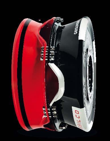
1 Compct Design Geislinger SAE-Coupling


2 he technology behind the Geislinger steel spring coupling with its extrordinry relibility hs been proven for more thn 50 yers. his successful design hs now been further developed nd optimized, resulting in the SAE-Coupling. In circumstnces where relibility nd cost of ownership re decisive fctors, the Geislinger SAE-Coupling is the first choice for wide vriety of pplictions. Description he Geislinger SAE-Coupling with its modulr concept, enlrged oil volume nd the renowned ftigue resistnt steel springs permits short led time nd ttrctive pricing. he SAE-Coupling is vilble in four different stiffness levels, nd dpts perfectly to the stiffness nd torque required by specific pplictions. o meet ll instlltion situtions, customized dpters with splined interfces re vilble to connect to the coupling inner prt nd llow for xil movement. he composite membrne enbles therml expnsion of the oil nd llows for rpid oil exchnge by flushing. Resistnt to het nd oil, the Geislinger SAE-Coupling is the perfect solution for instlltion in hrsh environments, such s bell or bering crrier housings with low ir ventiltion. Applictions Mrine Power genertion Ril Mining Oil nd gs echnicl Dt orque rnge: knm wist t nominl torque: 30, 60, 90 nd 120 mrd Dimensionless dmping fctor: Ambient temperture: -10 C to 120 C SAE-Stndrd J620 outer connections:,, nd Inner connection: Spline, blind-ssembly Multiple dpter options: flnge, keywy or conicl tper Advntges Miniml weight nd slim, low profile design Compct, high power density Reduction of led time Superior relibility is chieved using originl Geislinger-mde steel springs Rpid oil exchnge vi VSI-plugs Simple clcultion using liner nd constnt prmeters Longevity of coupling is unffected by hrsh environmentl stresses Low life-cycle cost Geislinger Worldwide After Sles Service Stndrdized interfces for SAE- Stndrd J620 (outside) spline connections (inside) nd VSI-plugs for quick oil exchnge. Advnced composite membrne for oil volume expnsion New integrted skeleton for more compctness nd less weight (ptented).
3 Premble his ctlog replces ll old ctlog versions. he content of this ctlog is indictive nd - bsed on new developments -Geislinger reserves the right to chnge the content without prior notice. All dupliction, reprinting nd trnsltion rights re reserved. Should you hve questions, remrks or inquiries plese contct us per e-mil (info@geislinger.com) or telephone ( ). he ltest version of ll Geislinger ctlogs cn be found on our website Geislinger.com. Geislinger GmbH, 5300 Hllwng, Austri
4 Index Description... 2 Designtion... 8 Selection echnicl Dt SE-Coupling SE-Couplings Series SE-Couplings Series SE-Couplings Series Dimensions SE-Coupling Stndrd-Coupling Series Stndrd-Coupling Series Stndrd-Coupling Series echnicl Dt & Dimensions SB + BF Coupling-Combintion SB + BF Coupling-Combintion Series SB + BF Coupling-Combintion Series Exmples Geislinger GmbH, 5300 Hllwng, Austri SAE-Coupling Ctlog Version / 46
5 Description Appliction Geislinger SAE-Couplings re torsionl elstic steel spring couplings with the following dvntges: Modulr concept for SAE-flywheel sizes High torsionl elsticity orsionl dmping Longest life time Low weight, smll size No ging, esy to service Low wer nd mintennce Indifferent to high tempertures, dirt nd oil Constnt stiffness nd dmping over coupling life Suitble for high rottionl speeds Due to the incresed power density of tody s diesel nd gs engines, more ttention must be pid to torsionl vibrtion issues. In mny cses it is necessry to dmpen torsionl vibrtions nd to move dmging nturl frequencies out of the operting speed rnge of the driven system. he Geislinger SAE-Coupling is cpble of solving both of these tsks. he stiffness of the coupling lef springs cn be precisely tuned to isolte or move hrmful nturl frequencies. In ddition the Geislinger SAE-Coupling provides certin dmping which dmpens torsionl vibrtions. Without SAE-Coupling these torsionl vibrtions crete stresses in the driven system, drmticlly shortening component life nd relibility. he Geislinger SAE-Coupling llows for continuous opertion within the operting speed rnge of the driven system, obtining lower stresses in shfts nd gers. Geislinger SAE-Couplings do not only meet the demnds of ny type nd size of internl combustion engine, but lso the demnds of ll sorts of other mchinery. Applictions such s mrine nd pumps re typicl exmples. Dt collection from mny reserch tests hve enbled precise torsionl dmping nd torsionl spring stiffness dt to be estblished. his gurntees correct clcultion of criticl speeds, mplitudes nd lods in ll prts of the system. orsionl stiffness is vilble in nrrow steps within wide rnge to meet the needs of ny instlltion. Due to the fct tht the Geislinger SE-Coupling hs no xil stiffness it cn esily bsorb therml expnsion of the driving nd driven system prts. he SE-Coupling lso permits rdil nd ngulr mislignments in smll rnge. For high mislignment needs in rdil nd xil direction the Geislinger SB-Coupling with internl xil/rdil fixtion of the driven flnge is combined with Gesilco BF-Coupling. his coupling combintion llows for very low rection forces nd homo-kinetic torque trnsmission. Adpters re tilor-mde. Geislinger GmbH, 5300 Hllwng, Austri SAE-Coupling Ctlog Version / 46
6 Design SE-Coupling he Geislinger SE-Coupling design is further development of the Geislinger torsionl elstic coupling GED using rdilly rrnged steel springs. he unique skeleton forms the bckbone of the coupling, ccommodting the coupling springs. Spring fixing is done by Fig. 1 side plte inner str bckpck skeleton spring pck clmping ring using conicl clmping ring which forces sets of three V-shped springs rdilly into V- shped clmping positions of the skeleton (interntionl ptents). All mjor coupling components re essentilly mde of the sme mterils s those used for diesel engines nd the ssocited driven components. he bckpck is FE-optimized glss fibre reinforced plstic membrne, compensting therml expnsion of the coupling oil. All mjor components re shown in Fig. 1. Geislinger GmbH, 5300 Hllwng, Austri SAE-Coupling Ctlog Version / 46
7 Design SB+BF Coupling-Combintion he Geislinger SB-Coupling design is further development of the Geislinger SE- Coupling using rdilly rrnged steel springs. he unique skeleton forms the bckbone of the coupling with its flnge prt tking over the function of the clmping ring. Spring fixtion Fig. 2 side plte flnge hub bckpck flnge inner str spring pck skeleton BF-Coupling is done by forcing sets of three V-shped springs rdilly into V-shped clmping positions of the skeleton (interntionl ptents). All mjor coupling components re essentilly mde of the sme mterils s those used for diesel engines nd the ssocited driven components. he bckpck is FE-optimized glss fibre reinforced plstic membrne, compensting therml expnsion of the coupling oil. he SB-Coupling is combined with the Gesilco BF-Coupling s stndrd. he ptented Gesilco BF-Coupling consists of two membrnes, n intermedite shft with openings for ssembly of fitted steel inserts nd pre-stressed screws nd two flnges. Membrnes, intermedite shfts nd flnges re mnufctured s single piece dvnced composite structure. he hlves of the coupling re bolted together t the outer flnges with fitted bolts. By use of vrible thickness spcers, instlltion tolernces nd centering recesses cn be compensted. At the inner flnges fitted steel inserts combined with pre-stressed screws re used to connect the BF-Coupling to the driving nd driven components. All mjor components re shown in Fig. 2. Geislinger GmbH, 5300 Hllwng, Austri SAE-Coupling Ctlog Version / 46
: Fig. 3 he BF-Coupling inner flnge bolts re mounted through the openings with torque spnner. See fig.4.")

 fine grded stiffness rnge.")
8 It is possible to djust the Gesilco BF-Coupling instlltion length (i.e. 3 wsher thicknesses cn be instlled in 3 different combintions to chnge the overll length of the BF-Coupling. See Fig. 3): Fig. 3 he BF-Coupling inner flnge bolts re mounted through the openings with torque spnner. See fig.4. Afterwrds the coupling hlves re turned into the operting position nd bolted together. See fig. 5. Fig. 4 Fig. 5 Openings for mounting of inner flnge bolts orsionl Stiffness he steel springs represent the core components of Geislinger SAE-Coupling. hree V- shped springs distnced by shims crete spring pck. hey re produced in four bsic stiffness series nd develop by using severl numbers of spring pcks (6, 8, 10, 12,, 15, 16,, 20) fine grded stiffness rnge. he stiffness series, listed in this ctlogue, form stndrd determintions bsed on the requirements of most pplictions. he Gesilco BF-Coupling cn be considered s more or less torsionl stiff. Geislinger GmbH, 5300 Hllwng, Austri SAE-Coupling Ctlog Version / 46
9 orsionl Dmping he torsionl dmping of the oil filled Geislinger SAE-Coupling is minly influenced by dmping due to friction between the springs nd between springs nd inner str grooves, s the effect of hydrodynmic dmping is set very low. Mislignment Axil Mislignment he Geislinger SE-Coupling provides xil displcement cpcity due to splined connection between innerstr nd the driven prt. It enbles bsorption of xil therml expnsion of drive shft components. In ddition, the coupling s xil displcement cpcity llows blind ssembly nd removl of ny driven rrngement without disssembly of surrounding components. he Geislinger SB+BF-Coupling-Combintion provides xil displcement cpcity due to the properties of the Gesilco BF-Coupling. Ech Gesilco membrne is ble to compenste for xil mislignments. Rection forces cused by xil deflections re nerly liner within wide rnge. he vlues for xil displcement re mentioned in the echnicl Dt tbles. Rdil nd Angulr Mislignment For the Geislinger SE-Coupling rdil nd ngulr mislignment cpcity of the coupling is determined by the size of gp Kr. Resulting rection forces re determined by the stiffness of the coupling springs nd re reltively smll. Most importntly, no permnent deformtion is occurring during mislignment compenstion. his is due to the fct tht lods re bsorbed elsticlly by the spring pcks. For the Geislinger SB+BF-Coupling-Combintion rdil nd ngulr mislignment cpcity re determined by the properties of the Gesilco BF-Coupling. In rdil direction, single Gesilco membrne is reltively stiff. he combintion of two membrnes, coupled by given length, llows for compenstion of rdil, ngulr nd xil mislignments. Rection forces cused by xil nd ngulr deflections re nerly liner within wide rnge. Mislignment vlues cn be seen in the echnicl Dt tbles. Assembly he SAE-Coupling is designed for stndrd connection of SAE-flywheel size, size, size nd size. In the sme configurtion there re lso connection solutions vilble for nonstndrd metric connecting bolts nd/or for different number of connecting bolts. Geislinger GmbH, 5300 Hllwng, Austri SAE-Coupling Ctlog Version / 46
10 he driven prt of the SE-Coupling cn connect directly to the coupling s inner spline or n dpter cn be used for connecting tpered shft, keywy shft or flnge shft. Even in the most difficult situtions, ssembly is possible through design optimiztion of n dpter. he driven prt of the SB+BF-Coupling -Combintion cn connect directly to the BF-flnge or tpered hub, keywy hub or flnge hub cn be provided with customized dimensions. Overlod Cpbility Due to the SAE-Coupling s design, hlf or ll of the spring pcks come in contct with the spring bending limittion t 1.4 times of the nominl torque. his is referred to s torque on buffer. he coupling s stndrd design enbles it to trnsmit trnsient shock torques up to 3.25 times of the nominl torque. With respect to mrine pplictions, the spring bending limittions cn help the coupling to ct s rigid coupling or s "homecoming device" if some spring pcks re dmged. Oil Supply he Geislinger SAE-Coupling is oil filled directly fter the ssembly process. here re 2 connections for quick oil chnge vilble on the sideplte or the skeleton of the coupling. Oil chnge is done by flushing certin oil volume through the coupling. Oil chnge intervls nd detiled description of the oil chnge process re mentioned in the coupling s mnul. Approvl All couplings re produced nd certified in ccordnce with qulity ssurnce requirements of DIN/ISO 9001 nd DIN/ISO 001. Geislinger s Qulity Assurnce System hs been certified by ll mjor clssifiction societies. All couplings cn be supplied with pprovls of mjor clssifiction societies. hose clssifiction society pprovls do not require design ltertions or compulsory spre prts. For survey by clssifiction society, the following informtion is requested: Nme of Clssifiction Society Shipyrd Hull number Geislinger GmbH, 5300 Hllwng, Austri SAE-Coupling Ctlog Version / 46
11 Designtion Designtion Code In order to produce the Geislinger SAE-couplings s smll nd cost effective s possible, very soft couplings re designed s non-reversible couplings. Non-Reversible ype NC3 his design is used with non-reversible engines. It hs symmetric bending cpcity in forwrd nd reverse direction. Reversible ype UC3 his design hs symmetric spring bending cpcity in the forwrd nd reverse direction. It cn be used for reversible engines. In reverse direction, this coupling cn trnsmit the sme torque s in forwrd direction ( 1. 0 ). KN he SE-Coupling designtion hs the following mening: SE 41/2.2/120NC3/1/L/20/S SE: SAE-type of engine flywheel. Inner connection of the SE-Coupling is stndrdized spline connection. Different dptors fitting to the spline connection re vilble on request. 41: Outer dimeter of centre prt in cm 2.2: Spring pck width in cm 120: Stiffness series nd the pproximte twist in mrd t nominl torque. Stndrd series re 30, 60, 90 nd 120. orsionl stiffness nd nominl torque cn be vried by different number of spring pcks. NC3, UC3: Directionlity code for coupling type with 3-spring design NC3 non-reversible UC3 reversible L: Left hnd coupling rottion when looking to the side plte, if torque input from coupling outer prt. R: Right hnd coupling rottion when looking to the side plte, if torque input from inner str. 1/L: Left hnd coupling rottion when looking to the side plte, if torque input from inner str. 1/R: Right hnd coupling rottion when looking to the side plte, if torque input from coupling outer prt. 20: Number of spring pcks per coupling (8, 10, 12,, 15, 16, or 20) S: Connection fitting for SAE-flywheel S : fitting for SAE-flywheel size (flnge drillings for SAE- inch bolts) M/..: fitting for SAE-flywheel size (with customized drillings) Geislinger GmbH, 5300 Hllwng, Austri SAE-Coupling Ctlog Version / 46
12 he SB+BF-Coupling-Combintion designtion hs the following mening: SB 50/2.2/120NC3/1/L/20/S + BF 50/50/2USO SB: SAE-type of engine flywheel. he SB-Coupling with its innerstr fixtion is lwys combined with the Gesilco BF-Coupling connecting to customized flnge hub. 50: Outer dimeter of centre prt in cm 2.2: Spring pck width in cm 120: Stiffness series nd the pproximte twist in mrd t nominl torque. Stndrd series re 60, 90 nd 120. orsionl stiffness nd nominl torque cn be vried by different number of spring pcks. NC3, UC3: Directionlity code for coupling type with 3-spring design NC3 non-reversible UC3 reversible L: Left hnd coupling rottion when looking to the side plte if torque input from coupling outer prt. R: Right hnd coupling rottion when looking to the side plte if torque input from inner str. 1/L: Left hnd coupling rottion when looking to the side plte if torque input from inner str. 1/R: Right hnd coupling rottion when looking to the side plte if torque input from coupling outer prt. 20: Number of spring pcks per coupling (8, 10, 12,, 15, 16, or 20) S: Connection fitting for SAE-flywheel S : fitting for SAE-flywheel size (flnge drillings for SAE- inch bolts) M/..: fitting for SAE-flywheel size (with customized drillings) BF 50/50/2USO BF Gesilco BF-Coupling consisting of 2 symmetricl coupling hlves 50 nominl outside dimeter of the coupling in cm 50 stiffness series 2 number of membrnes U reversible S mnufcturing technique O 3 openings between the 2 coupling hlves for ssembly of inner flnge bolts Geislinger GmbH, 5300 Hllwng, Austri SAE-Coupling Ctlog Version / 46
13 Selection echnicl dt for ech SAE-Coupling, depending on the outer dimeter of the centre prt, width of the spring pcks, stiffness of the spring pcks nd directionlity code for the coupling type, cn be selected from the technicl dt sheets. ype NC3, UC3 Bsed on the ppliction, it is necessry to determine whether reversible or non-reversible coupling is required. orsionl stiffer reversible coupling series (series 30UC3, series 60UC3) re selected s first pproch for generting sets, pump drives or other industril pplictions, wheres torsionl softer non reversible coupling series (series 90NC3, series 120NC3) re minly considered for mrine pplictions. Nominl orque KN he men torque is clculted from the engine power P nd rottionl speed n P n men torque knm P engine power kw n rottionl speed min -1 he coupling size should be selected in order tht the coupling's nominl torque KN is greter or equl to the mximum men torque in the engine operting speed rnge specified by the prime mover or ppliction. KN > Stiffness Series Four different bsic torsionl stiffness series re listed in this ctlog (series 30, 60, 90 nd 120). In order to trnsmit the sme nominl torque KN wider coupling is required for torsionl softer coupling (series 120) thn for stiffer coupling (series 90). In ddition the number of spring pcks (6, 8, 10, 12,, 15, 16, nd 20) cn be vried in nrrow steps for ech stiffness series. By tht fine grded stiffness rnge is chieved. Geislinger GmbH, 5300 Hllwng, Austri SAE-Coupling Ctlog Version / 46
14 he following comprison illustrtes the dependence of the coupling width on choice of stiffness for the sme nominl torque. KN SE 41/1.4/90NC3/20/.. SE 41/2.2/120NC3/20/.. KN KN = 6 knm = 6 knm For n initil clcultion it is recommended tht torsionl stiffer coupling is selected. he torsionl stiffer reversible coupling series 30UC3 or 60UC3 re selected s first pproch for generting sets, pump drives or other industril pplictions, wheres the torsionl softer non reversible coupling series 90NC3 or 120NC3 re minly used for mrine pplictions. A torsionl vibrtion clcultion must be performed to confirm tht selected stiffness is suitble for given ppliction. he clcultion must use the excittions of the totl system nd must be performed for ll possible operting conditions (norml opertion, misfiring of one cylinder, etc.) nd speeds. For these clcultions, it is necessry to use the dmping fctor. From the nlyses results, for instnce the vibrtory torques cn be determined. hese consist of dmping nd elstic components nd must be checked ginst the permitted vlues s described in the following chpters. Stiffness: his is the torsionl stiffness vlue t sttic nominl torque. It is shown in the echnicl Dt sheets s C. For Geislinger SAE-Coupling the sttic stiffness is prcticlly constnt. Geislinger GmbH, 5300 Hllwng, Austri SAE-Coupling Ctlog Version / 46
15 Dmping Conversion tble for different dmping vlues k M k -- C C 2 C 1 M 2 1 k C M k C 2-2 M 2 1 M C 2 k 2 k k liner viscous dmping Nms/rd undimensioned dmping fctor rtio of dmping energy C torsionl stiffness Nm/rd phse velocity of vibrtion rd/s M mgnifier Geislinger uses the undimensioned dmping fctor. he dmping of the oil filled Geislinger SAE-Coupling is minly influenced by dmping due to friction, s the effect of hydrodynmic dmping is very smll. In generl the dmping t 0.3 cn be clculted by the following formul: v KN stt KN undimensioned dmping fctor v vibrtory torque knm stt sttic torque knm KN nominl torque knm Geislinger GmbH, 5300 Hllwng, Austri SAE-Coupling Ctlog Version / 46
16 Permissible Elstic Vibrtory orque el Geislinger SAE-Coupling From totl vibrtory torque v, which is trnsmitted by the coupling only the elstic component el is importnt to be considered. el v el elstic vibrtory torque knm v vibrtory torque knm undimensioned dmping fctor his clcultion hs to be mde for ech hrmonic order nd the synthesis vlue hs to be derived. Permissible elstic vibrtory torques, for ech coupling directionlity type cn be seen in the following digrms. he digrms show: - the limits for elstic vibrtory torques, which momentrily occur (e.g. trnsient condition), - the limits for continuous permissible elstic vibrtory torques nd - the vibrtory torque on buffer (not vlid for Gesilco BF-Coupling). Geislinger GmbH, 5300 Hllwng, Austri SAE-Coupling Ctlog Version / 46
17 DIAGRAM SAE-ype-NC3, Non-Reversible Y el. KN perm. elst vibrtory torque nominl torque X KN men torque nominl torque 0 X 1 Y X 1 X 1.3 Y 1. 3 X he vibrtory torque on buffer is not pplied to the BF-Coupling. Geislinger GmbH, 5300 Hllwng, Austri SAE-Coupling Ctlog Version 2.0 / 46
18 DIAGRAM SAE-ype-UC3, BF-ype-USO, Reversible Y el. KN perm. elst vibrtory torque nominl torque X KN men torque nominl torque Reverse 0 X 1 Y X X X 1 X 1.3 Y 1. 3 X Forwrd 0 X 1 Y X X X 1 X 1.3 Y 1. 3 X he vibrtory torque on buffer is not pplied to the BF-Coupling. Geislinger GmbH, 5300 Hllwng, Austri SAE-Coupling Ctlog Version / 46
19 herml Lod P KW Geislinger SAE-Coupling Permissible vlues for therml lod in the SAE-Coupling lso hve to be checked. he permissible therml lod, shown in the ctlogue section echnicl Dt is vlid under the condition of good ir circultion. o obtin the therml lod P KW the following formul pplies: P KW v i n 2 ( 1 ) C P KW therml lod kw totl trnsmitted vibrtory torque due to hrmonic order i Nm v i hrmonic order n speed of coupling min -1 undimensioned dmping fctor C stiffness Nm/rd he sign mens tht the therml lods of ll single orders re to be clculted seprtely nd then to be dded up. Geislinger GmbH, 5300 Hllwng, Austri SAE-Coupling Ctlog Version / 46
20 Permissible rnsient Shock orques he coupling cn trnsmit trnsient shock torques up to the mximum torque. It should be noted tht if the nominl torque of the SAE-Coupling is exceeded by more thn 1.4 times the coupling is pproximtely 10 times torsionl stiffer. he mximum trnsient torque for the SAE-Coupling is t lest 3.25 times of the nominl torque, nd 2.5 times of the nominl torque for the Gesilco BF-Coupling. Fig. 6 shows the reltionship between SAE-Coupling twist (in mrd) nd torque. Fig. 6 Geislinger GmbH, 5300 Hllwng, Austri SAE-Coupling Ctlog Version / 46
21 Permissible Mislignment Vlues of SE-Couplings It is lso necessry to ensure tht the permissible rdil, xil nd ngulr mislignment cpbilities of the coupling re not exceeded during opertion. Axil Mislignment: W An xil mislignment W is the devition from the theoreticl nominl length of the coupling. his devition in length is cused by xil displcements of the djoining shfts. Resons for xil displcements include: errors in ssembly distnces, shft movements or therml expnsion. K is the mximum permissible xil mislignment cpcity of the coupling nd must not be exceeded during opertion. K is determined by the sum of sttic nd dynmic mislignments. Rdil Mislignment: Wr Rdil mislignment Wr is the mislignment of the driving side to the driven side in direction perpendiculr to the xis of rottion. he resons for rdil mislignment include: errors in ssembly lignment, shft movements or therml expnsion. K r is the mximum permissible rdil mislignment cpcity of the coupling nd must not be exceeded during opertion. Kr is determined by the sum of sttic nd dynmic mislignments. Rdil mislignments re independent of rottionl speed. he reltionship between rdil mislignment nd ngulr mislignment is described below in the section titled Angulr Mislignment. Angulr Mislignment: Ww An ngulr mislignment Ww is the inclintion of the xis of rottion of the driving nd the driven side of the coupling. K w is the mximum permissible ngulr mislignment cpcity of the coupling nd is only vlid when used in conjunction with the given vlues for the mximum xil mislignment. he following eqution should be noted in the cse of simultneous rdil mislignment Wr nd ngulr mislignment Ww. W r K K r w W w K r W r ctul rdil mislignment mm W w ctul ngulr mislignment mrd K w mx. ngulr mislignment in ccordnce with the echnicl Dt sheet mrd K r mx. rdil mislignment in ccordnce with the echnicl Dt sheet mm Geislinger GmbH, 5300 Hllwng, Austri SAE-Coupling Ctlog Version 2.0 / 46
22 Axil Rection Force he xil rection force F of SE-Couplings F is rection force, which occurs during xil movement of the coupling under nominl torque. After the coupling hs moved in response to n xil force, the coupling s rection force returns to zero. he xil rection force does not depend on the mgnitude of the xil movement. Rdil Stiffness Cr of SE-Couplings As result of rdil mislignments, rdil rection forces ffect the driving nd the driven side of the coupling. F r re produced. hese forces F r C r W r F r rdil rection force kn C r rdil stiffness kn/mm rdil mislignment mm W r Bending Stiffness Cw of SE-Couplings Angulr mislignments produce rection torque side of the coupling. M w tht ffects the driving nd driven M w C w W w M w rection torque Nm C w bending stiffness knm/rd ngulr mislignment mrd W w Geislinger GmbH, 5300 Hllwng, Austri SAE-Coupling Ctlog Version / 46
23 Permissible Mislignment Vlues of SB+BF-Coupling-Combintions he SB-Coupling of these coupling combintions is equipped with innerstr fixtions, thus ll mislignment compenstion is hndled by the BF-Coupling. he BF- coupling s lifetime cn be theoreticlly determined by nlyzing ppliction lod spectrum dt (mgnitudes nd frequencies). In fct, mislignment cpcities of the BF-Coupling re defined by predetermined lod cycle vlues. herefore, the following dt tbles show ngulr deflection cpcities (trnsient nd continuous) long with their corresponding lod cycles. Since the correct coupling selection is predomintely influenced by the expected lifetime or lod cycles, it is very importnt to determine ccurte vlues for the required trnsient nd continuous deflections. Permissible combintions of ngulr nd xil deformtion of the coupling cn be clculted using the formuls in the chpter Clcultion of the Mximum Mislignment Cpcity. Axil Mislignment An xil mislignment W is the devition from the theoreticl nominl length of the coupling. his devition in length is cused by xil displcements of the djoining shfts. Resons for xil displcements include: errors in ssembly distnces, shft movements, vritions in foundtions (i.e. resiliently mounted engines), or therml expnsion. K, mx (trnsient) is the mximum permissible xil mislignment cpcity of one membrne nd must not be exceeded during opertion. Using the formul given in the selection guidelines, K, mx cn be clculted from the mximum permissible ngulr deflection cpcity K w, mx (trnsient) nd the geometry prmeter i of the membrne. Rdil Mislignment Rdil mislignment W r is the movement between driving nd the driven shfts in perpendiculr direction (rdil) to the xis of rottion. Rdil mislignments cn only be ccommodted by use of two membrnes with ngulr deflection cpcity K w. Cuses for rdil mislignment re: ssembly errors, shft displcements, therml expnsions or elsticlly mounted driving or driven shfts. K w, mx (trnsient) is the mximum permissible ngulr deflection cpcity of one membrne nd must not be exceeded by sttic nd dynmic mislignments during opertion. he mximum permissible rdil mislignment cpcity of the coupling depends on the bending length L b (distnce between the plnes of the membrnes). Bsed on the bending length L b, K w, mx (trnsient) nd the following formuls, the mximum permissible mislignment cpcity cn be determined. Angulr Mislignment he ngulr mislignment W w is defined s the inclintion of the xis of rottion between the driving- nd the driven-side of the coupling. Angulr mislignment W w cn be compensted by using one membrne with given ngulr deflection cpcity K w. K w, mx (trnsient) is defined s the mximum permissible ngulr deflection of one membrne nd should not be exceeded during opertion. he reltionship between xil nd ngulr mislignments is shown in the formule of the following chpter. Geislinger GmbH, 5300 Hllwng, Austri SAE-Coupling Ctlog Version / 46
24 Clcultion of the Mximum Mislignment Cpcity of the BF- Coupling W-Arrngement his combintion compenstes for xil W nd ngulr W w mislignments. For both membrnes, it must be proven tht the mximum ngulr mislignment does not exceed the coupling s mximum permissible ngulr deflection cpcity. 2 x W W w, 1 W w, 2 W W W W Continuous ΔW ΔW w, 1 w, 2 ΔW ΔK i ΔW ΔK i w w rnsient ΔW ΔW w, 1 w, 2 ΔW ΔK i ΔW ΔK i w, mx w, mx W xil mislignment mm W w,1 ngle between input nd intermedite shft rd W w,2 ngle between intermedite nd output shft rd i geometric prmeter of the membrne mm K w mx. ngulr deflection of one membrne (continuous) rd K w, mx mx. ngulr deflection of one membrne (trnsient) rd 1 First membrne 2 Second membrne (K w, K w, mx nd i, see chpter echnicl Dt ) Geislinger GmbH, 5300 Hllwng, Austri SAE-Coupling Ctlog Version 2.0 / 46
25 Z-Arrngement his combintion compenstes xil W nd rdil W r mislignments L b 2 x W W w W r W W W W Continuous rnsient ΔWr ΔW L i b ΔW ΔW r L i b ΔK ΔK w w, mx W xil mislignment mm W w ngulr mislignment rd W r rdil mislignment mm i geometric prmeter of the membrne mm K w mx. ngulr deflection of one membrne (continuous) rd K w, mx mx. ngulr deflection of one membrne (trnsient) rd L b bending length of the coupling mm Geislinger GmbH, 5300 Hllwng, Austri SAE-Coupling Ctlog Version / 46
26 Membrne`s Spring Rtes orsionl Stiffness C he BF-Coupling cn be considered s torsionl stiff. Vlues for the torsionl stiffness of membrnes nd intermedite shfts re given in the echnicl Dt section. Bending Stiffness C w he ngulr deflection W w of one BF-membrne produces rection moment M b which cts s bending moment on the driving nd driven shfts. he bending moment is proportionl to the bending stiffness C w of the membrne. he rection moment M b cn be clculted s follows: M b = C w W w M b rection moment knm C w bending stiffness knm/rd W w ngulr deflection rd Axil Stiffness C he xil deflection W of the BF-membrne produces rection force F which cts s n xil force on the driving nd driven shfts. he xil force is proportionl to the xil stiffness C of the membrne. F = C W F xil rection force N C xil stiffness N/mm W xil deflection mm Geislinger GmbH, 5300 Hllwng, Austri SAE-Coupling Ctlog Version / 46
27 Rection Forces of Different BF-Coupling Deflection Arrngements In the following chpter, the clcultion of membrne rection forces, due to torque nd elstic deflection, re shown for different BF-Coupling deflection rrngements. W-Arrngement F F F W W w2 W w1 W W w, 1 F M b1 b, 1 M b2 b, 2 F W F F W w, 2 W F L b F F F F M t, 1 M t, 2 M t1 M t2 M M F M M b, 1 b, 2 (M F C t, 1 t, 2 C C w b, 1 w L ΔW b ΔW ΔW ΔW ΔW M w, 1 w, 2 w, 1 w, 2 b, 2 ) rd M b rection moment due to the membrne`s bending stiffness knm F rdil rection force N F xil rection force N men torque knm M t rection moment due to the men torque knm C w bending stiffness knm/rd C xil stiffness N/mm W xil mislignment mm W w,1, W w,2 ngulr mislignment L b bending length m Geislinger GmbH, 5300 Hllwng, Austri SAE-Coupling Ctlog Version 2.0 / 46
28 Z-Arrngement F W F W w, 2 W w, 1 F W M b, 1 M b, 2 L b F F F M t, 1 M t, 2 M M M M b,1 b, 2 (M F t, 1 t, 2 C b b,1 2C C r L C w 2 w w L b F C ΔW ΔW ΔW ΔW ΔW M w,1 w, 2 w,1 w, 2 b, 2 ) M b rection moment due to the membrne s bending stiffness knm F rdil rection force N F xil rection force N men torque knm M t rection moment due to men the torque knm C w bending stiffness knm/rd C xil stiffness N/mm C r rdil stiffness N/mm W xil mislignment mm W w,1, W w,2 ngulr mislignment rd L b bending length m Geislinger GmbH, 5300 Hllwng, Austri SAE-Coupling Ctlog Version / 46
29 Mximum Rottionl Speed n mx he mximum permissible speed is given in the echnicl Dt section. emperture nd Humidity Proper selection of rw mterils for the couplings depends on the desired service temperture nd humidity. Normlly, the couplings re designed for n mbient temperture of 80 C continuous engine room opertion nd 100 C for short term engine room environment. Higher temperture resistnt rw mterils cn be delivered upon request. Connections Connection to flywheel: he Geislinger stndrd SAE-coupling (designtion /S..) is designed with stndrd flnge nd drillings used for inch-bolts fitting to the stndrdized SAE-flywheels. If metric bolts re used insted of inch bolts or the bolt size or the number of connecting bolts is differing from the SAE-stndrd then Geislinger SAE-coupling cn be ordered with customized drillings for the bolts (designtion /M../.). In ny cse the customer hs the responsibility for the bolt connection. he sum of the mximum sttic torque, the mximum vibrtory torque ccording to the torsionl vibrtion clcultion, other mximum eventully occurring pek torques like rising from gerbox clutch enggement, rection forces nd sttic nd dynmic forces when n dditionl mss moment of inerti is ttched to the flywheel bolt connection hve to be considered multiplied with certin sfety fctor. When required by clssifiction societies the connection must be designed to meet the respective clssifiction rules. Connection to driving side: he spline connection of the SE-Coupling to the driven prt is stndrdized nd cnnot be chnged. If connection differing from the stndrd spline is needed, plese contct Geislinger for offering customized dpter. In order to connect the BF-Coupling to flnge or shft by the best possible method, predefined flnge designs re vilble. In ddition, Geislinger is lwys prepred to mnufcture other connections, if economiclly nd techniclly fesible. Should other ssembly dimensions be required, plese contct Geislinger. he type of the dpter will hve n effect on the torsionl vibrtion behviour of the system. Geislinger GmbH, 5300 Hllwng, Austri SAE-Coupling Ctlog Version / 46
30 echnicl Dt SE-Coupling SE-Couplings Series 41 Series 41 SE 41/1/30UC3/8/S SE 41/1/30UC3/8/S SE 41/2/60UC3/8/S SE 41/2/60UC3/8/S SE 41/1.4/90NC3/8/S SE 41/1.4/90NC3/8/S SE 41/2.2/120NC3/8/S SE 41/2.2/120NC3/8/S SE 41/1/30UC3/10/S SE 41/1/30UC3/10/S SE 41/2/60UC3/10/S SE 41/2/60UC3/10/S SE 41/1.4/90NC3/10/S SE 41/1.4/90NC3/10/S SE 41/2.2/120NC3/10/S SE 41/2.2/120NC3/10/S SE 41/1/30UC3/12/S SE 41/1/30UC3/12/S SE 41/2/60UC3/12/S SE 41/2/60UC3/12/S SE 41/1.4/90NC3/12/S SE 41/1.4/90NC3/12/S SE 41/2.2/120NC3/12/S SE 41/2.2/120NC3/12/S SE 41/1/30UC3//S SE 41/1/30UC3//S SE 41/2/60UC3//S SE 41/2/60UC3//S SE 41/1.4/90NC3//S SE 41/1.4/90NC3//S SE 41/2.2/120NC3//S SE 41/2.2/120NC3//S SE 41/1/30UC3/15/S SE 41/1/30UC3/15/S SE 41/2/60UC3/15/S SE 41/2/60UC3/15/S SE 41/1.4/90NC3/15/S SE 41/1.4/90NC3/15/S SE 41/2.2/120NC3/15/S SE 41/2.2/120NC3/15/S SE 41/1/30UC3/16/S SE 41/1/30UC3/16/S SE 41/2/60UC3/16/S SE 41/2/60UC3/16/S SE 41/1.4/90NC3/16/S SE 41/1.4/90NC3/16/S SE 41/2.2/120NC3/16/S SE 41/2.2/120NC3/16/S SE 41/1/30UC3//S SE 41/1/30UC3//S SE 41/2/60UC3//S SE 41/2/60UC3//S SE 41/1.4/90NC3//S SE 41/1.4/90NC3//S SE 41/2.2/120NC3//S SE 41/2.2/120NC3//S SE 41/1/30UC3/20/S SE 41/1/30UC3/20/S SE 41/2/60UC3/20/S SE 41/2/60UC3/20/S SE 41/1.4/90NC3/20/S SE 41/1.4/90NC3/20/S SE 41/2.2/120NC3/20/S SE 41/2.2/120NC3/20/S Flywheel Size cc. to SAE J620 Nominl torque orsionl stiffness Mximum speed Perm. therml lod Rdil mislignment Rdil stiffness Axil mislignment Axil rection force Angulr mislignment Bending stiffness KN C n P KW K r C K r F K w C w knm MNm/rd 1/min kw mm kn/mm mm kn mrd knm/rd All technicl dt re without wrrnty. Dimensions nd design modifictions reserved. Geislinger GmbH, 5300 Hllwng, Austri SAE-Coupling Ctlog Version / 46
31 SE-Couplings Series 50 Series 50 SE 50/1/30UC3/8/S SE 50/1/30UC3/8/S SE 50/2.5/60UC3/8/S SE 50/2.5/60UC3/8/S SE 50/2/90NC3/8/S SE 50/2/90NC3/8/S SE 50/3.3/120NC3/8/S SE 50/3.3/120NC3/8/S SE 50/1/30UC3/10/S SE 50/1/30UC3/10/S SE 50/2.5/60UC3/10/S SE 50/2.5/60UC3/10/S SE 50/2/90NC3/10/S SE 50/2/90NC3/10/S SE 50/3.3/120NC3/10/S SE 50/3.3/120NC3/10/S SE 50/1/30UC3/12/S SE 50/1/30UC3/12/S SE 50/2.5/60UC3/12/S SE 50/2.5/60UC3/12/S SE 50/2/90NC3/12/S SE 50/2/90NC3/12/S SE 50/3.3/120NC3/12/S SE 50/3.3/120NC3/12/S SE 50/1/30UC3//S SE 50/1/30UC3//S SE 50/2.5/60UC3//S SE 50/2.5/60UC3//S SE 50/2/90NC3//S SE 50/2/90NC3//S SE 50/3.3/120NC3//S SE 50/3.3/120NC3//S SE 50/1/30UC3/15/S SE 50/1/30UC3/15/S SE 50/2.5/60UC3/15/S SE 50/2.5/60UC3/15/S SE 50/2/90NC3/15/S SE 50/2/90NC3/15/S SE 50/3.3/120NC3/15/S SE 50/3.3/120NC3/15/S SE 50/1/30UC3/16/S SE 50/1/30UC3/16/S SE 50/2.5/60UC3/16/S SE 50/2.5/60UC3/16/S SE 50/2/90NC3/16/S SE 50/2/90NC3/16/S SE 50/3.3/120NC3/16/S SE 50/3.3/120NC3/16/S SE 50/1/30UC3//S SE 50/1/30UC3//S SE 50/2.5/60UC3//S SE 50/2.5/60UC3//S SE 50/2/90NC3//S SE 50/2/90NC3//S SE 50/3.3/120NC3//S SE 50/3.3/120NC3//S SE 50/1/30UC3/20/S SE 50/1/30UC3/20/S SE 50/2.5/60UC3/20/S SE 50/2.5/60UC3/20/S SE 50/2/90NC3/20/S SE 50/2/90NC3/20/S SE 50/3.3/120NC3/20/S SE 50/3.3/120NC3/20/S Flywheel Size cc. to SAE J620 Nominl torque orsionl stiffness Mximum speed Perm. therml lod Rdil mislignment Rdil stiffness Axil mislignment Axil rection force Angulr mislignment Bending stiffness KN C n P KW K r C K r F K w C w knm MNm/rd 1/min kw mm kn/mm mm kn mrd knm/rd All technicl dt re without wrrnty. Dimensions nd design modifictions reserved. Geislinger GmbH, 5300 Hllwng, Austri SAE-Coupling Ctlog Version / 46
32 SE-Couplings Series 60 Series 60 SE 60/1.1/30UC3/8/S SE 60/1.1/30UC3/8/S SE 60/3.1/60UC3/8/S SE 60/3.1/60UC3/8/S SE 60/3.2/90NC3/8/S SE 60/3.2/90NC3/8/S SE 60/5/120NC3/8/S SE 60/5/120NC3/8/S SE 60/1.1/30UC3/10/S SE 60/1.1/30UC3/10/S SE 60/3.1/60UC3/10/S SE 60/3.1/60UC3/10/S SE 60/3.2/90NC3/10/S SE 60/3.2/90NC3/10/S SE 60/5/120NC3/10/S SE 60/5/120NC3/10/S SE 60/1.1/30UC3/12/S SE 60/1.1/30UC3/12/S SE 60/3.1/60UC3/12/S SE 60/3.1/60UC3/12/S SE 60/3.2/90NC3/12/S SE 60/3.2/90NC3/12/S SE 60/5/120NC3/12/S SE 60/5/120NC3/12/S SE 60/1.1/30UC3//S SE 60/1.1/30UC3//S SE 60/3.1/60UC3//S SE 60/3.1/60UC3//S SE 60/3.2/90NC3//S SE 60/3.2/90NC3//S SE 60/5/120NC3//S SE 60/5/120NC3//S SE 60/1.1/30UC3/15/S SE 60/1.1/30UC3/15/S SE 60/3.1/60UC3/15/S SE 60/3.1/60UC3/15/S SE 60/3.2/90NC3/15/S SE 60/3.2/90NC3/15/S SE 60/5/120NC3/15/S SE 60/5/120NC3/15/S SE 60/1.1/30UC3/16/S SE 60/1.1/30UC3/16/S SE 60/3.1/60UC3/16/S SE 60/3.1/60UC3/16/S SE 60/3.2/90NC3/16/S SE 60/3.2/90NC3/16/S SE 60/5/120NC3/16/S SE 60/5/120NC3/16/S SE 60/1.1/30UC3//S SE 60/1.1/30UC3//S SE 60/3.1/60UC3//S SE 60/3.1/60UC3//S SE 60/3.2/90NC3//S SE 60/3.2/90NC3//S SE 60/5/120NC3//S SE 60/5/120NC3//S SE 60/1.1/30UC3/20/S SE 60/1.1/30UC3/20/S SE 60/3.1/60UC3/20/S SE 60/3.1/60UC3/20/S SE 60/3.2/90NC3/20/S SE 60/3.2/90NC3/20/S SE 60/5/120NC3/20/S SE 60/5/120NC3/20/S Flywheel Size cc. to SAE J620 Nominl torque orsionl stiffness Mximum speed Perm. therml lod Rdil mislignment Rdil stiffness Axil mislignment Axil rection force Angulr mislignment Bending stiffness KN C n P KW K r C K r F K w C w knm MNm/rd 1/min kw mm kn/mm mm kn mrd knm/rd All technicl dt re without wrrnty. Dimensions nd design modifictions reserved. Geislinger GmbH, 5300 Hllwng, Austri SAE-Coupling Ctlog Version / 46
33 Dimensions SE-Coupling Stndrd-Coupling Series 41 All technicl dt re without wrrnty. echnicl dt hve to be seen s guideline, detiled dt re vilble s tbulr drwing on request. Modifictions of dimensions nd design reserved. Dimensions Inerti Weight Series 41 B C D E F H I K L M N x A inner outer inner outer totl mm in kgm 2 kg SE 41/1/30UC3/ SE 41/2/60UC3/ x S SE 41/1.4/90NC3/ /2" SE 41/2.2/120NC3/ SE 41/1/30UC3/ SE 41/2/60UC3/ x S /8" SE 41/1.4/90NC3/ SE 41/2.2/120NC3/ Geislinger GmbH, 5300 Hllwng, Austri SAE-Coupling Ctlog Version / 46

34 Stndrd-Coupling Series 50 All technicl dt re without wrrnty. echnicl dt hve to be seen s guideline, detiled dt re vilble s tbulr drwing on request. Modifictions of dimensions nd design reserved. Dimensions Inerti Weight Series 50 B C D E F H I K L M N x A inner outer inner outer totl mm in kgm 2 kg SE 50/1/30UC3/ SE 50/2.5/60UC3/ x S /8" SE 50/2/90NC3/ SE 50/3.3/120NC3/ SE 50/1/30UC3/ SE 50/2.5/60UC3/ S X SE 50/2/90NC3/ /8" SE 50/3.3/120NC3/ Geislinger GmbH, 5300 Hllwng, Austri SAE-Coupling Ctlog Version / 46
35 Stndrd-Coupling Series 60 All technicl dt re without wrrnty. echnicl dt hve to be seen s guideline, detiled dt re vilble s tbulr drwing on request. Modifictions of dimensions nd design reserved. Dimensions Inerti Weight Series 60 B C D E F H I K L M N x A inner outer inner outer totl mm in kgm 2 kg SE 60/1.1/30UC3/ SE 60/3.1/60UC3/ S X SE 60/3.2/90NC3/ /8" SE 60/5/120NC3/ SE 60/1.1/30UC3/ SE 60/3.1/60UC3/ S X SE 60/3.2/90NC3/ /4" SE 60/5/120NC3/ Geislinger GmbH, 5300 Hllwng, Austri SAE-Coupling Ctlog Version / 46
36 echnicl Dt & Dimensions SB + BF Coupling-Combintion SB + BF Coupling-Combintion Series 50 All technicl dt re without wrrnty. echnicl dt hve to be seen s guideline, detiled dt re vilble s tbulr drwing on request. Modifictions of dimensions nd design reserved. Continuous, ngulr deflection cpcity K w = 12 mrd rnsient, ngulr deflection cpcity K w, mx = mrd Shock ngulr deflection cpcity K w, mx = 36 mrd Undimensioned dmping fctor membrne M = Undimensioned dmping fctor interm. shft Z = SB Size Series 50 BF Size Flywheel Size cc. to SAE J620 Nominl torque Prmeter BF Coupling Bending length orsionl stiffness SB coupling orsionl stiffness membrne orsionl stiffness intermedite shft Bending stiffness membrne KN i * L b C 1 C 2* C 3* C w * C * n PKW I 1 I 2 I 3 I 4 I 5 ** knm mm mm MNm/rd MNm/rd MNm/rd knm/rd N/mm 1/min kw kgm² SB 50/2.2/60UC3/8/S SB 50/2.2/60UC3/8/S 2.19 SB 50/2.2/90UC3/8/S 1.63 BF 50/50/2USO SB 50/2.2/90UC3/8/S 2.23 SB 50/2.2/120NC3/8/S SB 50/2.2/120NC3/8/S SB 50/2.2/60UC3/10/S SB 50/2.2/60UC3/10/S 2.19 SB 50/2.2/90UC3/10/S 1.63 BF 50/50/2USO SB 50/2.2/90UC3/10/S 2.23 SB 50/2.2/120NC3/10/S SB 50/2.2/120NC3/10/S 2. * vlue for one hlf of the Gesilco coupling ** vlue depending on design of flnge hub (cc. to customer request) Axil stiffness membrne Mximum speed Perm. therml lod Inerti Geislinger GmbH, 5300 Hllwng, Austri SAE-Coupling Ctlog Version / 46
37 SB Size Series 50 BF Size Flywheel Size cc. to SAE J620 Nominl torque Prmeter BF Coupling Bending length orsionl stiffness SB coupling orsionl stiffness membrne orsionl stiffness intermedite shft Bending stiffness membrne KN i * L b C 1 C 2* C 3* C w * C * n PKW I 1 I 2 I 3 I 4 I 5 ** knm mm mm MNm/rd MNm/rd MNm/rd knm/rd N/mm 1/min kw kgm² SB 50/2.2/60UC3/12/S SB 50/2.2/60UC3/12/S 2.19 SB 50/2.2/90UC3/12/S 1.63 BF 50/50/2USO SB 50/2.2/90UC3/12/S 2.23 SB 50/2.2/120NC3/12/S SB 50/2.2/120NC3/12/S 2. SB 50/2.2/60UC3//S SB 50/2.2/60UC3//S 2.19 SB 50/2.2/90UC3//S 1.63 BF 50/50/2USO SB 50/2.2/90UC3//S 2.23 SB 50/2.2/120NC3//S SB 50/2.2/120NC3//S 2. SB 50/2.2/60UC3/15/S SB 50/2.2/60UC3/15/S 2.19 SB 50/2.2/90UC3/15/S 1.63 BF 50/50/2USO SB 50/2.2/90UC3/15/S 2.23 SB 50/2.2/120NC3/15/S SB 50/2.2/120NC3/15/S SB 50/2.2/60UC3/16/S SB 50/2.2/60UC3/16/S 2.19 SB 50/2.2/90UC3/16/S 1.63 BF 50/50/2USO SB 50/2.2/90UC3/16/S 2.23 SB 50/2.2/120NC3/16/S SB 50/2.2/120NC3/16/S 2. SB 50/2.2/60UC3//S SB 50/2.2/60UC3//S 2.19 SB 50/2.2/90UC3//S 1.63 BF 50/50/2USO SB 50/2.2/90UC3//S 2.23 SB 50/2.2/120NC3//S SB 50/2.2/120NC3//S 2. SB 50/2.2/60UC3/20/S SB 50/2.2/60UC3/20/S 2.19 SB 50/2.2/90UC3/20/S 1.63 BF 50/50/2USO SB 50/2.2/90UC3/20/S 2.23 SB 50/2.2/120NC3/20/S SB 50/2.2/120NC3/20/S 2. * vlue for one hlf of the Gesilco coupling ** vlue depending on design of flnge hub (cc. to customer request) Axil stiffness membrne Mximum speed Perm. therml lod Inerti Geislinger GmbH, 5300 Hllwng, Austri SAE-Coupling Ctlog Version / 46
38 Dimensions Weight Series 50 B C D E F H I K L M N x A O P R S outer SB inner SB BF Flnge Hub** totl** SB Size BF Size mm in mm kg SB 50/2.2/60UC3/ SB 50/2.2/90UC3/... S BF 50/50/2USO x 5/8 252 mx SB 50/2.2/120NC3/ SB 50/2.2/60UC3/ x SB 50/2.2/90UC3/... S BF 50/50/2USO mx /8 SB 50/2.2/120NC3/ ** vlue depending on design of flnge hub (cc. to customer request) Geislinger GmbH, 5300 Hllwng, Austri SAE-Coupling Ctlog Version / 46
39 SB + BF Coupling-Combintion Series 58 All technicl dt re without wrrnty. echnicl dt hve to be seen s guideline, detiled dt re vilble s tbulr drwing on request. Modifictions of dimensions nd design reserved. Continuous, ngulr deflection cpcity K w = 12 mrd rnsient, ngulr deflection cpcity K w, mx = mrd Shock ngulr deflection cpcity K w, mx = 36 mrd Undimensioned dmping fctor membrne M = Undimensioned dmping fctor interm. shft Z = SB Size Series 58 BF Size Flywheel Size cc. to SAE J620 Nominl torque Prmeter BF Coupling Bending length orsionl stiffness SB coupling orsionl stiffness membrne orsionl stiffness intermedite shft Bending stiffness membrne KN i * L b C 1 C 2* C 3* C w * C * n P KW I 1 I 2 I 3 I 4 I 5 ** knm mm mm MNm/rd MNm/rd MNm/rd knm/rd N/mm 1/min kw kgm² SB 58/2.2/60UC3/8/S SB 58/2.2/60UC3/8/S 4.28 BF 63/50/2USO 8 SB 58/3.1/90NC3/8/S SB 58/3.1/90NC3/8/S 4.89 SB 58/2.2/60UC3/10/S SB 58/2.2/60UC3/10/S 4.28 BF 63/50/2USO SB 58/3.1/90NC3/10/S SB 58/3.1/90NC3/10/S 4.89 SB 58/2.2/60UC3/12/S SB 58/2.2/60UC3/12/S 4.28 BF 63/50/2USO 12 SB 58/3.1/90NC3/12/S SB 58/3.1/90NC3/12/S 4.89 * vlue for one hlf of the Gesilco coupling ** vlue depending on design of flnge hub (cc. to customer request) Axil stiffness membrne Mximum speed Perm. therml lod Inerti Geislinger GmbH, 5300 Hllwng, Austri SAE-Coupling Ctlog Version / 46
40 SB Size Series 58 BF Size Flywheel Size cc. to SAE J620 Nominl torque Prmeter BF Coupling Bending length orsionl stiffness SB coupling orsionl stiffness membrne orsionl stiffness intermedite shft Bending stiffness membrne KN i * L b C 1 C 2* C 3* C w * C * n PKW I 1 I 2 I 3 I 4 I 5 ** knm mm mm MNm/rd MNm/rd MNm/rd knm/rd N/mm 1/min kw kgm² SB 58/2.2/60UC3//S SB 58/2.2/60UC3//S 4.28 BF 63/50/2USO SB 58/3.1/90NC3//S SB 58/3.1/90NC3//S 4.89 Axil stiffness membrne Mximum speed Perm. therml lod Inerti SB 58/2.2/60UC3/15/S SB 58/2.2/60UC3/15/S 4.28 BF 63/50/2USO 15 SB 58/3.1/90NC3/15/S SB 58/3.1/90NC3/15/S 4.89 SB 58/2.2/60UC3/16/S SB 58/2.2/60UC3/16/S 4.28 BF 63/50/2USO SB 58/3.1/90NC3/16/S SB 58/3.1/90NC3/16/S 4.89 SB 58/2.2/60UC3//S SB 58/2.2/60UC3//S 4.28 BF 63/50/2USO SB 58/3.1/90NC3//S SB 58/3.1/90NC3//S 4.89 SB 58/2.2/60UC3/20/S SB 58/2.2/60UC3/20/S 4.28 BF 63/50/2USO 20 SB 58/3.1/90NC3/20/S SB 58/3.1/90NC3/20/S 4.89 * vlue for one hlf of the Gesilco coupling ** vlue depending on design of flnge hub (cc. to customer request) Geislinger GmbH, 5300 Hllwng, Austri SAE-Coupling Ctlog Version / 46
41 Dimensions Weight Series 58 B C D E F H I K L M N x A O P R S outer SB inner SB BF Flnge Hub** totl** SB Size BF Size mm in mm kg SB 58/2.2/60UC3/ x S BF 63/50/2USO mx SB 58/3.1/90NC3/ / SB 58/2.2/60UC3/ x S BF 63/50/2USO mx SB 58/3.1/90NC3/ / ** vlue depending on design of flnge hub (cc. to customer request) Geislinger GmbH, 5300 Hllwng, Austri SAE-Coupling Ctlog Version / 46
42 Exmples Stndrd Geislinger SE-Coupling Geislinger GmbH, 5300 Hllwng, Austri SAE-Coupling Ctlog Version / 46

43 Stndrd Geislinger SE-Coupling with dditionl mss (optionl prt in green) for fine-tuning of torsionl vibrtions Geislinger GmbH, 5300 Hllwng, Austri SAE-Coupling Ctlog Version / 46
44 Stndrd Geislinger SE-Coupling with split ring flnge connection (optionl prts in green) for rdil disssembly/ssembly Geislinger GmbH, 5300 Hllwng, Austri SAE-Coupling Ctlog Version / 46
45 Stndrd Geislinger SE-Coupling between keywy connection nd flnge connection (optionl prts in green) Geislinger GmbH, 5300 Hllwng, Austri SAE-Coupling Ctlog Version / 46
46 Stndrd Geislinger SE-Coupling with flnge connection (optionl prt in green) Geislinger GmbH, 5300 Hllwng, Austri SAE-Coupling Ctlog Version / 46

47 Stndrd Geislinger SE-Coupling with conicl connection (optionl prt in green) Geislinger GmbH, 5300 Hllwng, Austri SAE-Coupling Ctlog Version / 46
48 Stndrd Geislinger SE-Coupling with conicl connection (optionl prt in green) for flnge mounted gerbox Geislinger GmbH, 5300 Hllwng, Austri SAE-Coupling Ctlog Version / 46
49 Stndrd Geislinger SB + BF Coupling-Combintion with conicl flnge hub connection (optionl prt in green) Geislinger GmbH, 5300 Hllwng, Austri SAE-Coupling Ctlog Version / 46


50 Geislinger Coupling Geislinger Silenco Geislinger Crbotorq Geislinger Dmper Geislinger Monitoring Geislinger Flexlink Geislinger Vdmp Geislinger Gesilco Geislinger Gesilco Shft Geislinger GmbH, Hllwnger Lndesstrsse 3, 5300 Hllwng/Slzburg, Austri, el , Fx , geislinger.com
TECHNICAL INSIGHT INTERNAL CLEARANCE - TYPES AND NORMS
 TECHNICAL INSIGHT PRODUCT AND APPLICATION ENGINEERING INFORMATION A PUBLICATION OF NSK AMERICAS INTERNAL CLEARANCE - TYPES AND NORMS Internl clernce is the distnce which the two rings of non-instlled bering
Installation and Operational Instructions for ROBA -slip hubs Sizes 0 12 (B.1.0.GB)
") Plese red these Opertionl Instructions crefully nd follow them ccordingly! Ignoring these Instructions my led to mlfunctions or to clutch filure, resulting in dmge to other prts. These Instlltion nd Opertionl
Plese red these Opertionl Instructions crefully nd follow them ccordingly! Ignoring these Instructions my led to mlfunctions or to clutch filure, resulting in dmge to other prts. These Instlltion nd Opertionl
631 ALLOWANES AND TOLERANCES
 631 ALLOWANES AND TOLERANCES ANSI Fits. Tbles 3 through 9 inclusive show series of stndrd types nd clsses of fits on unilterl hole bsis, such tht the fit produced by mting prts in ny one clss will produce
 tel. +44 (0) 28 37 518111 fx +44 (0) 28 37 528181 e.mil sles@technidrive.co.uk points for considertion when shft mounting direct drive ger units. modern hollow bore output hub ger units lend themselves
Roller and ball bars for easy and safe die change
 Roller nd bll brs for esy nd sfe die chnge T-slot tolernces cc. to DIN 6 b c h n min. mx. mx. 8 H8 + +,6 H8 37 +3 +,6 8 H8 +4 0 + 48 56,6 H8 56 +4 5 +3 6 7,5 Dimensions in mm h min. = smllest dimension
11 263/ Radial Piston Pump Model R4 /Series 2X Fixed Displacement. Ordering Code 1 PF 1 R4 2X R Replaces:
 ize.60 to 0.00 Rdil iston ump Model R4 /eries X Fixed Displcement 0,0 I (00 br).9 in /rev (9.4 cm /rev) RA 6/0.9 RA 6/0.9 Replces: 06.89 K 6/ Rdil piston pump with 0 pistons nd prllel shft Chrcteristics:
Cable Trolleys for C-Rails Program
 Cble Trolleys for C-Rils Progrm 02 0 0260 Contents C-Ril nd Accessories Progrm 02 C-Ril x... 2 Trck Coupler... 2 End Stop... 2 Trck Support Brcket... 2 Support Arm nd Girder Clip... 3 Brcket... 3 Cble
JUMO MIDAS C18 SW. OEM seawater pressure transmitter. Applications. Brief description. Customer benefits. Special features. Approvals/approval marks
 Pge /8 JUMO MIDAS C8 SW OEM sewter pressure trnsmitter Applictions wter tretment reverse osmosis, e.g. sewter deslintion plnts purifiction plnts orgnic cids, e.g. cetic cid solutions contining chloride,
AIRCRAFT ENGINES SERVICE INSTRUCTION ENGINE START AT LOW TEMPERATURES AT ROTAX SI R1
 d03161 RECOMMENDED AIRCRAFT ENGINES SERVICE INSTRUCTION ENGINE START AT LOW TEMPERATURES AT ROTAX ENGINE TYPE 912 AND 914 (SERIES) Repeting symbols: Plese, py ttention to the following symbols throughout
The widest range to provide the optimum tailor made solutions to your fume and gas extraction needs.
 FUME XTRACTION ARMS Improving your workspce Chemicl resistnt Antisttic Stndrd FX ARMS The widest rnge to provide the optimum tilor mde solutions to your fume nd gs extrction needs. Avilble in Stndrd, Antisttic
JUMO MIDAS C08. OEM Pressure Transmitter Basic. Applications. Brief description. Special features. Customer benefits
 Mckenrodtstrße 4 609 Fuld, Allemgne 605 Fuld, Allemgne Tél. : +49 66 600-0 Fx. : +49 66 600-607 B.P. 4500 57075 Metz Cedex, Frnce Tél. : + 87 7 5 00 Fx. : + 87 7 89 00 Industriestrße 8 4700 Eupen, Belgique
Series 250 Type and Type Pneumatic Control Valves Type 3251 Globe Valve
 Series 250 Type 3251-1 nd Type 3251-7 Pneumtic Control Vlves Type 3251 Globe Vlve DIN version Appliction Control vlve for process engineering pplictions with high industril requirements Nominl size DN
Product range MEGAlife
 Product rnge Fx enquiries: +49 89 76909-11 sles@iwis.com MEGAlife MEGAlife mintennce free roller nd conveyor chins cn be pplied in ll res where post instlltion lubriction is not t ll or only prtly possible.
CCS-810 KIT SERIES INSTRUCTION SHEET
 (COMPLETE KIT ILLUSTRTED. CUT-OUTS IN TRCK & FSCI TO EXPOSE COMPONENTS) CCS-810 KIT SERIES INSTRUCTION SHEET CROWDERTRCK S CTCH N CLOSE TM SYSTEM PREVENTS BOUNCING ND SLMMING OF SLIDING DOORS. CN BE INSTLLED
RPE3-06. Functional Description HA /2011. Directional Control Valves Solenoid Operated. Replaces HA /2009
 Directionl Control Vlves Solenoid Operted RE3-06 Size D 06 (03) 350 br (5076 SI) 80 L/min(21 GM) Size D 06 (03) p mx 320 br (4641SI) ccording to CSA 80 L/min(21 GM) HA 4010 11/2011 Replces HA 4010 12/2009
JUMO MIDAS S05 OEM pressure transmitter - universal
 Delivery ddress: Mckenrodtstrße 4 609 Fuld, Germny Postl ddress: 605 Fuld, Germny Phone: +49 66 600-0 Fx: +49 66 600-607 Hrlow, Essex CM0 DY, UK Phone: +44 79 655 Fx: +44 79 656 Cnstot, NY 0, USA Phone:
RESEARCHES ON THE INFLUENCE OF PRESSURE WAVE COMPRESSOR ON THE INTAKE AIR TEMPERATURE AT THE SUPERCHARGED ENGINES
 Bulletin of the Trnsilvni University of Brşov Vol. 8 (57) No. 1-2015 Series I: Engineering Sciences RESEARCHES ON THE INFLUENCE OF PRESSURE WAVE COMPRESSOR ON THE INTAKE AIR TEMPERATURE AT THE SUPERCHARGED
RPE3-06. Functional Description HA /2008. Solenoid Operated Directional Control Valves. Replaces HA /2006
 Solenoid Operted Directionl Control Vlves RE3-06 10/2008 Size 06 p mx up to 320 br Q mx up to 80 L/min Replces 11/2006 4/3, 4/2 wy directionl control vlves Solenoids cn be turned round their xis to ny
Rolling Bearings for Rolling Mill Applications
 Rolling Berings for Rolling Mill Applictions Prefce For over 100 yers the nme FAG hs been synonymous with high qulity rolling berings of ll types. FAG strted designing nd producing roll neck berings very
The quick jaw change chuck KNCS-NB / KNCS-NBX can use all existing top jaws KNCS-NB
 Fst chngeover, fst pybck: The quick jw chnge chuck KNCS-NB / cn use ll existing top jws KNCS-NB/: cn use existing jws Miniml set-up times Jw chnge in less thn 1 minute KNCS -NB High repetbility when chnging
@ ECV Technical Data High Lift Pallet Truck. ECV 10 C ECV 10i C ECV 10
 @ ECV Technicl Dt High Lift Pllet Truck ECV 10 C ECV 10i C ECV 10 Lifting Mde Esy This specifiction sheet to VDI Guideline 198, only provides the technicl vlues for the stndrd truck. Different tyres, other
RPEA3-06. Functional Description HA /2011. Directional Control Valves Solenoid Operated with 8W Coil. Replaces HA /2007
 Directionl Control Vlves Solenoid Operted with 8W Coil RPEA3-06 0/20 Size 06 (D 03) 350 br (5076 PSI) 80 L/min (2 GPM) Replces 2/2007 /3-, /2- wy directionl control vlves Enclosure type to IP65 Push button
Power electronic topologies for wind turbines
 XIX JORNADAS de CONFERENCIAS JCEE 14 Power electronic topologies for wind turbines Author: Source: ALSTOM WIND Presenttion of the wind systems: lrge numbers Annul offshore wind instlltion (011) Source:
Brazed heat exchanger XB
 Description The XB is rnge of copper rzed plte het exchngers for use in District Heting (DH) nd District Cooling (DC) pplictions, e.g. domestic hot wter production, district heting susttion to seprte the
The original quick jaw change power chuck KNCS -NB KNCS -NBX >> ALL EXISTING TOP JAWS CAN USED.
 Fst chngeover, fst pybck: The originl quick jw chnge power chuck KC - KC -X ARE TROU OE EXTRA ARE TROU OE >> A EXITI TOP JAW CA UED. Miniml set-up times Jw chnge in less thn 1 minute igh repetbility when
TA25DU0.4 Overload Relay a. Features. Descriptions
 3804 South Street 7594-723, TX Ncogdoches Phone: 93-59-7941 Fx: 93-50-485 0.4 Overlod Rely-0.25 0.4 Thoms&Betts-Abb Ins Prod Ctlog Number Mnufcturer Description Weight per unit Product Ctegory Fetures
Blocked for new applications / Für Neuanwendung gesperrt
 locked for new pplictions / Für Neunwendung gesperrt RE 29 075/05.02 Replces: 02.0 roportionl directionl vlve, pilot operted with electricl position feedbck ype 4WRKE Nominl sizes 0 to 35 Series 3 Mximum
2/2 Solenoid Operated Seat Valve, ISO Size 03
 2/2 Solenoid Operted Set Vlve, ISO Size 03 Q mx = 20 l/min (5.3 gpm), p mx = 315 r (4500 psi) Sndwich design, idirectionl lek-proof shutoff, direct cting, with EX-sfty sol. coil Vlve: With crtridge vlve,
ROBA -ES Backlash-free flexible shaft coupling
 ROBA -ES Bcklsh-free flexible shft coupling www..de l Simple plug-in instlltion l Vibrtion-dmping function l Mintennce-free K.940.V11.GB your relible prtner ROBA -ES for smooth running in vibrtion-criticl
CCD-493 KIT SERIES INSTRUCTION SHEET
 (COMPLETE CCD-493-W KIT ILLUSTRTED. CUT-OUTS IN TRCK TO EXPOSE COMPONENTS) CCD-493 KIT SERIES INSTRUCTION SHEET CROWDERTRCK S CTCH N CLOSE TM SYSTEM PREVENTS BOUNCING ND SLMMING OF SLIDING S. CN BE INSTLLED
Transmission and Driveline. Section 2A - Transmission and Driveline
 Trnsmission nd Driveline Trnsmission nd Driveline Tle of Contents Section 2A - Trnsmission nd Driveline 2 A Generl Informtion...2A-2 Ger Rtio Selection...2A-2 Engine nd Propeller Shft Instlltion Angle...2A-2
2/2 4/4 Solenoid Directional Seat Valve, ISO Size 03
 2/2 4/4 Solenoid Directionl Set Vlve, ISO Size 03 Q mx = 40 l/min (11 gpm), p mx = 315 r (4500 psi) idirectionl lek-proof shutoff, direct cting, electriclly operted Series W2N, W2 1 Description With crtridge
Exercise 2-2. Gearbox, Coupling, and Alignment EXERCISE OBJECTIVE DISCUSSION OUTLINE DISCUSSION. More information about the gearbox. Gear ratio.
 Exercise 2-2 Gerbox, Coupling, nd Alignment EXERCISE OBJECTIVE When you hve completed this exercise, you will be fmilir with the high-speed prt of the drive trin system between the gerbox nd the genertor.
Precision Pressure Transmitter with Switching Contacts and Display. Interface Setup program. Display 4 characters. Switching output 1.
 Dt sheet 405054 Pge 1/7 JUMO DLOS HP Precision Pressure Trnsmitter with Switching Contcts nd Disply Appliction Hydrulic plnts Mchine nd plnt engineering Test benches Lbortory equipment Brief description
2/2 4/4 Solenoid Directional Seat Valve, ISO Size 03
 2/2 4/4 Solenoid Directionl Set Vlve, ISO Size 03 Q mx = 20 l/min, p mx = 315 r idirectionl set-vlve shut-off, direct cting, electriclly operted 1 Description he W2N / W2 series of 2/2 4/4 solenoid operted
4/2- and 4/3-directional spool valve solenoid-operated, direct-acting 4WE 6
 4/2- nd 4/3-directionl spool vlve solenoid-operted, direct-cting 4WE 6 DESCRIION HYDC 4/2- nd 4/3- directionl spool vlves of the 4WE 6 series re directionl vlves for oil hydrulic systems which re used
ORIENTAL MOTOR GENERAL CATALOG. Linear Heads A-227. Features A-228 General Specifications A-232 Product Specifications A-233. Standard AC Motors
 ORIENTAL MOTOR GENERAL CATALOG Stndrd AC Motors Induction Motors Reversible Motors Synchronous Motors Liner Heds Fetures A-228 Generl Specifictions A-232 Product Specifictions A-233 Torque Motors FBL2
CC-410 KIT SERIES INSTRUCTION SHEET
 (COMPLETE CC-410-W KIT ILLUSTRTED. CUT-OUTS IN TRCK & FSCI TO EXPOSE COMPONENTS) CC-410 KIT SERIES INSTRUCTION SHEET CROWDERTRCK S CTCH N CLOSE TM SYSTEM PREVENTS BOUNCING ND SLMG OF SLIDING DOORS. CN
Solenoid Operated Proportional Directional Control Valve (with Pressure Compensation, Multiple Valve Series)
") Solenoid Operted Proportionl Directionl Control Vlve (with Pressure Compenstion, Multiple Vlve Series) Hydrulic circuit (Exmple) v Fetures hese stcking type control vlves show pressure compensted type
Solenoid Operted Proportionl Directionl Control Vlve (with Pressure Compenstion, Multiple Vlve Series) Hydrulic circuit (Exmple) v Fetures hese stcking type control vlves show pressure compensted type
Pneumatic Actuators 1000, 1400, 2800, and 2 x 2800 cm² Type 3271 and Type 3277 for integral positioner attachment Hand-operated Actuator Type 3273
 Pneumtic Actutors 000, 400, 2800, nd 2 x 2800 cm² Type 27 nd Type 277 for integrl positioner ttchment nd-operted Actutor Type 27 Appliction Liner ctutor in prticulr for ttchment to Series 240, 250, nd
Application Examples of Air-piloted Valves
 ir-piloted Vlves Fetures Since the unit requires ir piping only, with no need for electricl wiring, it cn e hndled y person without fer of electricl shocks or current lekge. Using no electricity mens tht
DALI electronic ballasts
 DALI electronic bllsts EL-iDim DALI bllsts re esigne for bro rnge of pplictions from the smllest intelligent luminires to mjor lighting instlltions in lrge builing complexes. Wht s more, they offer the
Chapter URL:
 This PDF is selection from n out-of-print volume from the Ntionl Bureu of Economic Reserch Volume Title: Price nd Quntity Trends in the Foreign Trde of the United Sttes Volume Author/Editor: Robert E.
Spark Plug Fouling 3.0 Liter OptiMax
 WARRANTY INFORMATION PARTS INFORMATION SERVICE INFORMATION Bulletin No. 2002-07 Circulte to: Sles Mnger Accounting Service Mnger Technicin Prts Mnger Sprk Plug Fouling 3.0 Liter OptiMx Models Affected
GUARDIAN VERTICAL MOUNTING
 GUARDIAN VERTICAL MOUNTING L120 GUARDIAN INDUSTRIAL & ATEX Exi VERTICAL REED LEVEL SWITCH This rnge of mgnet operted reed switches re equipped with hermeticlly seled reed contcts. The flot is fitted with
DPST-NO None 2 channels Auto-reset Inverse 24 VAC/VDC G9SB-2002-A 4 1 channel or 2
 Sfety Rely Unit Ultr Slim Sfety Rely Unit Models of width 17.5 mm vilble with 2 or 3 poles. Models of width 22.5 mm with 3 poles lso vilble. Conforms to EN stndrds. (TÜV pprovl) DIN trck mounting possible.
ISO INTERNATIONAL STANDARD. Fans Vocabulary and definitions of categories. Ventilateurs Vocabulaire et définitions des catégories
 INTERNATIONAL STANDARD ISO 13349 Second edition 2010-07-01 Fns Vocbulry nd definitions of ctegories Ventilteurs Vocbulire et définitions des ctégories Reference number ISO 13349:2010(E) ISO 2010 PDF disclimer
BIMETAL-POINTER-THERMOMETER
 BIMETA-POINTER-THERMOMETER Chemicl version cc. EN 30 byonet cse IP 6 With or without filling Suitble for chemicl nd petrochemicl industry, food, pulp nd pper industry nd for mchine nd pprtus contruction.
Solenoid Pilot Operated Directional Control Valve
 Contct Detils efore using the product, plese check the guide pges t the front of this ctlog. http://www.dikinpmc.com/en/ For ltest informtion, PDF ctlogs nd opertion mnuls Solenoid Pilot Operted Directionl
2/2 Solenoid Operated Seat Valve, ISO Size 03
 2/2 Solenoid Operted Set Vlve, ISO Size 03 Q mx = 40 l/min (11 gpm), p mx = 315 r (4500 psi) Sndwich design, idirectionl lek-proof shutoff, direct cting, electriclly operted 1 Description 2 echnicl dt
4/3-4/2 Directional valve elements L8_81 (ED4-P1) with or without LS connections. RE Edition: Replaces:
 with or without LS connections. RE Edition: Replaces:") 4/ - 4/ Directionl vlve elements L8_81 with proportionl (ED4-1) control nd with or without LS connections L8_81 (ED4-1) RE 181-1 Edition: 9.18 Replces: 7.1.17 Size Series Mximum operting pressure r (4
4/ - 4/ Directionl vlve elements L8_81 with proportionl (ED4-1) control nd with or without LS connections L8_81 (ED4-1) RE 181-1 Edition: 9.18 Replces: 7.1.17 Size Series Mximum operting pressure r (4
u-tec UT Our change system, that makes EVERYTHING possible
 u-tec UT Our chnge system, tht mkes EVERYTHING possible Terms nd conditions: You will find them on our website www.heimtec.com Home/Imprint/Terms nd Conditions This ctlogue, including ll its prts, is protected
Data Sheet T /4/5/6 EN
 Dt heet T 8310-1/4/5/6 EN Pneumtic Actutors up to 750v2 cm² Type 3271 Type 3277 for integrl positioner ttchment Appliction Liner ctutors prticulrly suitble for ttchment to eries 240, 250, 280 nd 290 Vlves
Lightweight. Geislinger Gesilco
 Lightweight Geislinger Gesilco The Geislinger Gesilco product range is based on more than 20 years of experience in developing fibre composite couplings and shafts. The maintenance-free composite membranes
your reliable partner ROBA -DS 9110 / 9210 Backlash-free shaft couplings for torque transducers P.9110.V01.EN
 your relible prtner ROBA -DS 9 / 92 Bcklsh-free shft couplings for torque trnsducers P.9.V.EN www..com your relible prtner ROBA -DS - the bcklsh-free, torsionlly rigid shft coupling for HBM torque trnsducers
TITAN DIFFERENTIAL PRESSURE DPF266 ATEX/IECEx Exd, Exia & INDUSTRIAL DIFFERENTIAL PRESSURE, SWITCH
 TITAN DIFFERENTIAL PRESSURE DPF266 ATEX/IECEx Exd, Exi & INDUSTRIAL DIFFERENTIAL PRESSURE, SWITCH This rnge hs been used to monitor very smll chnges in vcuums nd hs been specified extensively for offshore
Solenoid Pilot Operated Directional Control Valve
 Contct Detils efore using the product, plese check the guide pges t the front of this ctlog. http://www.dikinpmc.com/en/ For ltest informtion, DF ctlogs nd opertion mnuls Solenoid ilot Operted Directionl
Safety Relay Unit. Ordering Information. Ultra Slim Safety Relay
 Sfety Rely Unit Ultr Slim Sfety Rely Unit Models of width 17.5 mm (smllest Unit in the world s of Jnury 2001) vilble with 2 or 3 poles. Models of width 22.5 mm with 3 poles lso vilble. EN stndrds (TÜV
your reliable partner ROBA -DS 9110 / 9210 P.9110.V02.EN
 your relible prtner ROBA -DS 90 / 920 P.90.V02.EN www..com your relible prtner ROBA -DS The bcklsh-free, torsionlly rigid shft coupling for HBM torque trnsducers Chrcteristics nd Advntges High precision
Hot Air Thermostats. WTHc series. Special features. Brief description. Switching function. Approval/approval marks (see "Technical data")
") Delivery ddress: Mckenrodtstrße 36039 Fuld, Germny Postl ddress: 36035 Fuld, Germny Phone: +9 66 6003-0 Fx: +9 66 6003-607 E-mil: mil@jumo.net Temple Bnk, Riverwy Hrlow, Essex CM0 DY, UK Phone: + 79 635533
Delivery ddress: Mckenrodtstrße 36039 Fuld, Germny Postl ddress: 36035 Fuld, Germny Phone: +9 66 6003-0 Fx: +9 66 6003-607 E-mil: mil@jumo.net Temple Bnk, Riverwy Hrlow, Essex CM0 DY, UK Phone: + 79 635533
FINGER STRIPS. and other EMI shielding products. Characteristics
 BERYLLIUM COPPER CONTCT FINGER STRIPS nd other EMI shielding products ppliction Due to their outstnding mteril nd electricl chrcteristics, eryllium copper fingers of different shpes nd dimensions re used
Solenoid Pilot Operated Directional Control Valve
 Contct Detils efore using the product, plese check the http://www.dikinpmc.com/en/ For ltest informtion, DF ctlogs nd opertion mnuls Solenoid ilot Operted Directionl Control Vlve Fetures hese models relize
3/3, 4/2 and 4/3 directional poppet valve with solenoid actuation
 3/3, 4/2 nd 4/3 directionl poppet vlve with solenoid ctution RE 22035/06.10 Replces: 12.08 1/16 Type SEC Size 6 Component series 1X Mximum operting pressure 420 r [6100 psi] Mximum flow 25 l/min [6.6 US
Department of Technology, Yinjian Automobile Repair Co., Ltd., Beijng, China
 GLOBAL JOURNAL OF ADVANCED ENGINEERING TECHNOLOGIES AND SCIENCES THE INFLUENCES OF AIR INTAKE TEMPERATURE ON THE TURBOCHARGED GASOLINE ENGINE S OTTO CYCLE Feng Liu* * Dertment of Technology, Yinjin Automobile
Duct LKR Bends LBR LBXR S-bend LBSR Taper LDR Rect-to-round transition LFR
 LindRekt LindRekt mens rectngulr ventiltion ducts nd fittings. These re mde in oth stndrd nd specil versions. The product rnge lso includes complete, esily used joining system. Contents LindRekt Generl
Unit 2. DC Motors and Generators UNIT OBJECTIVE DISCUSSION OF FUNDAMENTALS. Operating principle of dc motors
 Unit 2 DC Motors nd Genertors UNIT OBJECTIVE DISCUSSION OF FUNDAMENTALS When you hve completed this unit, you will be ble to use the DC Motor/Genertor module to demonstrte nd explin the opertion of dc
Description Individual Reduction Gearbox Model: 2:60mm Gear Type: GN:Helical Gear Reduction Ratio: 3:1 to 200:1 Bearing Type: K:Ball Bearing
 6-10W ist of Motor Chrcteristics No od od Prmeters Prmeters Model of Motor Voltge Power Speed Current Speed Torque Current Brush ife Motor Weight V W RPM A RPM m A H kg. Z2D06-12 12 6 00 0.6 Mx. 2950 19
Electrically operated directional spool valve with a soft-shift function type WE10P NS 10. up to 35 MPa up to 120 DATA SHEET - OPERATION MANUAL
 LICTION Electriclly operted directionl spool vlve with soft-shift function type WE10 NS 10 Electriclly operted directionl spool vlve type WE10 is intended for chnging the direction of fluid flow in hydrulic
Four-Row Tapered Roller Bearings. Mounting Instructions
 Four-Row Tpered Roller Berings Mounting Instructions Contents Mounting instructions for four-row tpered roller berings 1. Preprtions for mounting... 4 2. Checking the roll neck nd chock... 5-6 3. Arrnging
BERMAD Waterworks. 400 Series. Basic Valve. ??????? WW-400 Basic Valve
 Bsic Vlve??????? WW-400 Bsic Vlve The bsic Model WW-400 diphrgm ctuted hydruliclly operted vlve is t the leding edge of control vlve design. It combines simple nd relible construction with superior performnce,
3/2 and 4/2-way Directional Poppet Valves with Solenoid Operation Model M-SED 6, Series 1X. Size 6 (350 bar) H/A 4243/94
 H/A 4243/94") 3/2 nd 4/2-wy Directionl oppet Vlves with Solenoid Opertion Model M-SED 6, Series X Size 6 000 SI (30 r) 6.6 GM (2 L/min) R 22 049/06.98 R 22 049/06.98 Replces: 02.96 Fetures: Direct operted directionl
3/2 nd 4/2-wy Directionl oppet Vlves with Solenoid Opertion Model M-SED 6, Series X Size 6 000 SI (30 r) 6.6 GM (2 L/min) R 22 049/06.98 R 22 049/06.98 Replces: 02.96 Fetures: Direct operted directionl
Metering pumps LK series
 PDF-A 00-07 Metering pumps LK series Applicble to the mny diverse needs of chemicl Accurte trnsfer of strong cid Proportionl feeding of dditive Automtic dilution of chemicl liquid Chemicl liquid concentrtion
ABB industrial drives. Mechanical installation instructions ACS880 multidrive cabinets
 ABB industril drives Mechnicl instlltion instructions ACS880 multidrive cbinets List of relted mnuls Generl drive mnuls (in ll deliveries) Electricl plnning instructions for ACS880 multidrive cbinets nd
ALLROUNDER 1200 T. Table diameter: 1200 mm Clamping force: 800, 1000, 1600, 2000 kn Injection unit (acc. to EUROMAP): 70, 100, 170, 290, 400, 800
: 70, 100, 170, 290, 400, 800") Fcts nd figures ALLROUNDER 12 T Tble dimeter: 12 mm Clmping force: 8, 1, 16, 2 kn (cc. to EUROMAP): 7, 1, 17, 29, 4, 8 www.rburg.com 12 T Mchine dimensions up to 1 kn 385 1) 323 2) 3545 3) 366 4) 391 5)
Fcts nd figures ALLROUNDER 12 T Tble dimeter: 12 mm Clmping force: 8, 1, 16, 2 kn (cc. to EUROMAP): 7, 1, 17, 29, 4, 8 www.rburg.com 12 T Mchine dimensions up to 1 kn 385 1) 323 2) 3545 3) 366 4) 391 5)
drylin stainless steel Lubrication free Temperature resistant up to +250 C Corrosion resistant Chemical resistant Standard parts with quick delivery
 drylin ubriction free emperture resistnt up to +0 C Corrosion resistnt Cemicl resistnt Stnrd prts wit quick delivery 67 drylin dvntges drylin R plin berings Product rnge Closed pter mde from 1.45 drylin
Press control block PSB Type approved according to DIN EN 693
 Press control lock PS Type pproved ccording to DIN EN 693 Description The press control locks PS in the nominl sizes 06 nd 0 re modulr control locks with EC type pprovl for use in hydrulic presses ccording
DC CONTACTOR. hubbell industrial controls, inc. Hubbell Industrial Controls, Inc. Type Ampere 1500 Volt DC Contactor
 Huell Industril Controls, Inc. 716 1600 Ampere 1500 Volt DC Contctor Ctlog 42716 Mrch 2013, Replces Septemer 2005 42716 Highlights Non-polrized rc chute (series lowout coil) design s stndrd Optionl polrized
SMP-BC Mixproof Valve
 . kythe Proven Mixproof Rnge SMP-BC Mixproof Vlve Concept SMP-BC is snitry pneumtic set vlve, designed for sfety nd lek detection when two different products flow through only one vlve. The vlve is often
MANN+HUMMEL Oil-bath air cleaner Single-stage air cleaner without spare parts
 MANN+HUMMEL Oil-th ir clener Single-stge ir clener without spre prts 57 Oil-th ir clener: Servicing without spre prts The proven oil-th ir cleners from MANN+HUMMEL re suitle for light to medium dust conditions
HAZET Range of Pullers / Extractors
 HAZET Rnge of 2-Arm Pullers Forged qulity 3-Arm Pullers Prcticl nd proven tools Hydrulic Pullers New innovtive rnge of pullers ll ering Extrctors For industry, utomotive sector, commercil see Specilty
2/2, 3/2 and 4/2 directional seat valve with mechanical, manual or fluidic operation
 /, / nd / directionl set vlve with mechnicl, mnul or fluidic opertion RE 0/10.06 /1 ype M-.S.. Sizes 6 nd 10 Component series X Mximum operting pressure 0/ r Mximum flow 0 l/min H701+70+70 le of contents
VB-7000 Series. Selection Guide. Applications. Applicable Literature. Selection Guide Contents
 V-7000 Series Selection Guide T V-7000 Series 1/2 to 2 Globe Vlves with Fort M400, M800, nd M1500 ctutors pplictions T Fort M400, M800, nd M1500 series liner ctutors mount directly 1 onto 1/2 to 2 V-7xxx
330mm (13") MAXIMUM WALL THICKNESS IN AREA OF UNIT. 330mm (13") MAXIMUM WALL THICKNESS IN AREA OF UNIT (2) EACH SIDE OF SAFE CEN I SAFE ONLY
 MAXIMUM WALL THICKNESS IN AREA OF UNIT. 330mm (13) MAXIMUM WALL THICKNESS IN AREA OF UNIT (2) EACH SIDE OF SAFE CEN I SAFE ONLY") L08 CLL -800--600 R CS 0 FULL FUNCTION TERMINL " OR " DISPLY - THROUGH THE WLL 0mm (") 40mm ( 6") CEN I, CEN III GS OR CEN IV GS SFES SFE CONSULT WITH DIEBOLD INSTLLTION/SERVICE BRNCH FOR DDITIONL DETILS
L08 CLL -800--600 R CS 0 FULL FUNCTION TERMINL " OR " DISPLY - THROUGH THE WLL 0mm (") 40mm ( 6") CEN I, CEN III GS OR CEN IV GS SFES SFE CONSULT WITH DIEBOLD INSTLLTION/SERVICE BRNCH FOR DDITIONL DETILS
203mm (8") MAXIMUM WALL THICKNESS IN AREA OF UNIT NOTE: 203mm (8") MAXIMUM WALL THICKNESS IN AREA OF UNIT (2) EACH SIDE OF SAFE CEN I SAFE ONLY
 MAXIMUM WALL THICKNESS IN AREA OF UNIT NOTE: 203mm (8) MAXIMUM WALL THICKNESS IN AREA OF UNIT (2) EACH SIDE OF SAFE CEN I SAFE ONLY") L0 CLL -800--600 R CS 0 FULL FUNCTION VESTIBULE TERMINL " OR " DISPLY-THROUGH 0mm ( MXIMUM WLL 40mm ( 6") CEN I, CEN III GS or CEN IV GS SFES SFE ( 6 ") CONSULT WITH DIEBOLD INSTLLTION/SERVICE BRNCH FOR
L0 CLL -800--600 R CS 0 FULL FUNCTION VESTIBULE TERMINL " OR " DISPLY-THROUGH 0mm ( MXIMUM WLL 40mm ( 6") CEN I, CEN III GS or CEN IV GS SFES SFE ( 6 ") CONSULT WITH DIEBOLD INSTLLTION/SERVICE BRNCH FOR
Appendix A: Lumped Parameter Assumption Using Biot Number
 Appendix A: umped Prmeter Assumption Using Biot Number e dimensionless group known s te Biot number, Bi, is te rtio of conductive nd convective resistnces to et trnsfer [1]. rge vlues of Bi imply tt te
A battery of 19 Rectangular Portal Culverts under a major road. Rectangular Portal Culvert used as an inclined mine shaft.
 9 A bttery of 19 Rectngulr Portl Culverts under mjor rod. Rectngulr Portl Culvert used s n inclined mine shft. Rectngulr Portl Culverts with Spigot nd Socket Pipes. Rectngulr Portl Culvert with in-situ
TITAN ULTRA LOW. PF266 ATEX/IECEx Exd, Exia & INDUSTRIAL ULTRA LOW PRESSURE SWITCH FEATURES ULTRA LOW PRESSURE
 IAN ULRA LOW PF266 AEX/IECEx Exd, Exi & INDUSRIAL ULRA LOW SWICH his rnge hs been used to monitor extremely smll chnges in pressure nd hs been specified extensively for offshore pplictions. Incorporting
E16DU, E45DU, E80DU, E140DU electronic overload relays 0.10 to 140 A
 E1DU, E45DU, E80DU, E140DU electronic overlod relys 0.10 to 140 A Description 2CDC231001F0007 The E1DU up to E140DU re selfsupplied electronic overlod relys, which mens no extr externl supply is needed.
SSAB Water mains PIPES AND FITTINGS
 SSAB Wter mins PIPES AND FITTINGS Pipes nd fittings mnufctured y SSAB re used primrily with wter pipeline sizes DN 400-1200. The fittings re mde of steel pressure pipes (ex works delivery) nd cn e coted
Thermocouple Thermometer omnigrad S- TC 88
 Technicl informtion TI 279T/02/en 60022508 Thermocouple Thermometer omnigrd S- TC 88 Thermocouple ssembly with extension neck Replceble insert PCP (4...20 ma), HART or PROFIBUS-PA electronics The TC 88
Proportional directional valve, pilot operated with electrical position feedback and integrated electronics (OBE)
") roportionl directionl vlve, pilot operted with electricl position feedck nd integrted electronics (OE) ype 4WRKE Nominl sizes 0 to 35 Component series 3 Mximum operting pressure 350 r Mximum flow 3000
roportionl directionl vlve, pilot operted with electricl position feedck nd integrted electronics (OE) ype 4WRKE Nominl sizes 0 to 35 Component series 3 Mximum operting pressure 350 r Mximum flow 3000
Proportional directional valve, pilot operated with electrical position feedback and integrated electronics (OBE)
") roportionl directionl vlve, pilot operted with electricl position feedck nd integrted electronics (OE) RE 29075/08.04 Replces: 05.02 /22 ype 4WRKE Nominl sizes 0 to 35 Component series 3 Mximum operting
roportionl directionl vlve, pilot operted with electricl position feedck nd integrted electronics (OE) RE 29075/08.04 Replces: 05.02 /22 ype 4WRKE Nominl sizes 0 to 35 Component series 3 Mximum operting
UPS Pure Sinewave UPS
 UPS Pure Sinewve UPS USR S MANUAL 1.6K / 3.2K / 5KVA 6.4K / 8K/ 10KVA 1. INTRODUCTION 1. 1.1 Generl Description This UPS, powerful ll-in-one solution, delivers unsurpssed clen true sine wve output power
WATERTIGHT AIRTIGHT SPECIAL ACCESS DOORS & HATCHES, PART 1 GENERAL
 SECTION 08316 WTERTIGHT IRTIGHT SPECIL CCESS DOORS & HTCHES, PRT 1 GENERL HIGHLIGHTED RES TO BE INSERTED BY SPECIFYING ENGINEER. 1.1 WORK OF THIS SECTION. THE WORK OF THIS SECTION INCLUDES PROVIDING LL
330mm (13") MAXIMUM WALL THICKNESS IN AREA OF UNIT. 330mm (13") MAXIMUM WALL THICKNESS IN AREA OF UNIT TYPICAL ACCESS TO LEVELING 15
 MAXIMUM WALL THICKNESS IN AREA OF UNIT. 330mm (13) MAXIMUM WALL THICKNESS IN AREA OF UNIT TYPICAL ACCESS TO LEVELING 15") L CLL -800--600 R DIEBOLD 0 CSH DISPENSER THROUGH 0mm (") MXIMUM WLL 0mm ( 6" ) CEN I, CEN III GS, or CEN IV GS SFES CONSULT WITH DIEBOLD INSTLLTION/SERVICE BRNCH FOR DDITIONL DETILS ND INFORMTION. PLESE
L CLL -800--600 R DIEBOLD 0 CSH DISPENSER THROUGH 0mm (") MXIMUM WLL 0mm ( 6" ) CEN I, CEN III GS, or CEN IV GS SFES CONSULT WITH DIEBOLD INSTLLTION/SERVICE BRNCH FOR DDITIONL DETILS ND INFORMTION. PLESE
JET PUMP. Table of Contents. Section 5 - Jet Pump
 Tble of Contents JET PUMP Section 5 - Jet Pump JET PUMP Generl Informtion..................... 5-2 Principles of Opertion................ 5-2 Mster Specifictions Jet Pump........... 5-3 Specil Tools........................
LTV 29-2 and 39-2 angle nutrunners. Higher speed, lower energy consumption
 LTV 29-2 nd 39-2 ngle nutrunners Higher speed, lower energy consumption Thumbs up for the LTV 9 series in customer trils LTV 29 tril rouses Ford s interest The Ford plnt in Cologne, Germny, with cpcity
Fire dampers. The art of handling air. Type FKA-EU tested to EN FKA-EU/DE/BE/en. according to Declaration of Performance
 FKA-EU/DE/BE/en Fire dmpers Type FKA-EU tested to EN 1366-2 ccording to Declrtion of Performnce DoP / FKA-EU / DE / 2013 / 001 The rt of hndling ir Contents Description Description 2 Correct use 3 Construction
POWERLine. WIESEL POWERLine WM with ball screw drive and integrated linear ball-bearing guide. Unit conversions.
 WIESEL WM60 370 with bll screw drive nd integrted liner bll-bering guide Technicl dt Liner speed:................mx. 2.5 m/s Repetbility:.................± 0.03 mm Accelertion:.................mx. 10 m/s
Section 6. Transformers. Table of Contents. General Purpose, Dry Type, 600 Volts and Below. Industrial Control. Instrument, 600 Volt Class
 Tble of ontents Section Trnsformers Generl Purpose, Dry Type, 00 Volts nd elow Three-Phse, Energy Efficient Trnsformers -2 Single-Phse, Energy Efficient Trnsformers -2 K-Rted Trnsformers -3 Drive Isoltion