General Operating Instructions for Load Suspension Devices
|
|
|
- Avis Johns
- 5 years ago
- Views:
Transcription


1 ENGLISH Translation of the Original General Operating Instructions for Load Suspension Devices Use for crane and stacker operation GRIPPERS & LIFTING CLAMPS LOAD BEAMS & CRANE BEAMS C-HOOKS & COIL HOOKS LOADING FORKS & CRANE FORKS CRANE CAGES & TRANSPORT RACKS STACKER BEAMS Kurschildgen GmbH Hebezeugbau
2 Table of Contents 1. Definition of a load suspension device 3 2. Design bases 3 3. Machine description (technical product data) 3 4. General information 4 5. Legend to the safety information on the LSD 5 6. Grippers for crane operation Frictionally engaged grippers for transport Internal grippers Spindle gripper Carton gripper Parallel gripper Block grab Internal gripper of compact 3-gripping claw design Coefficients of friction for frictionally engaged grippers Positively engaged grippers and lifting clamps for transport/emptying Box grabs (for steel containers) Fork C-hook CST-WTA (for steel containers) Universal grippers Coil grippers KLT gripper (for plastic containers) Fork C-hook C-KLT (for plastic containers) Round stock grabber Supporting bolts with a spherical retainer and an eccentric Internal gripper with an integrated actuating handle Spindle gripper Frictionally and positively engaged turning grippers for transporting/turning Spindle gripper Box turning gripper Coil turning gripper Spindle gripper ST type spindle gripper (without turning function) / STD (with turning function) ST-I type internal spindle gripper(frictionally engaged) / ST-IU (positively engaged) ST-K type spindle gripper (without turning function) / ST-K type (with turning function) Lifting beams for crane and stacker operation General information Girder-type beams Laminated-hook and side-hook lifting beams Spreader beams / shoring beams Low-design and negative-design beams Lifting beam with an adjustable crane suspension Transverse beams BIG-BAG beams Frame beams arm beams IBC container beam/pallet beam Crane cage/load rack for material transport Gas cylinder lifter Lifting beam for stacker operation C-hooks for crane operation Coil tilting hook C-hook with a load lifting magnet Crane forks Information on the CE mark and risk assessment Mounting / test / maintenance / repair Mounting Mounting the adjusting elements on the TAV and TAV-H beams Mounting the HC/C shackle type Mounting the VBG coupling links Mounting the eye-type load hook of the TA beam Mounting the substitute traps Test Test in the manufacturer's premises Test prior to the first commissioning Test prior to each application Regular test Extraordinary tests Wearing limits for friction linings Deformation and wearing limits of bearing elements Maintenance Repair Notes Drawings Spare parts Appendix TEST SHEET Appendix TEST Notes
3 1. Definition of a load suspension device A non-hoist module or component which ensures the gripping of the load and is attached between the machine and the load or to the load itself and intended to become an integral part of the load and separately put into circulation. Fasteners and their components are also regarded as load suspension devices. 2. Design bases Machinery directive 2006/42 EC DIN EN DIN EN ISO DIN DGUV Rule Machine description (technical product data) Cranes - Safety - Non-fixed lifting attachments S- Safety of machinery - General principles for design - Risk assessment and risk reduction (ISO 12100:2010) Lifting appliances - load suspension devices, loads and forces - Definitions Operation of load suspension devices in hoist operation Manufacturer: Load Suspension Devices: Series: Type designation : Carrying capacity: Gripping range: Working width: Turning radius/immersion depth: Tightening moment/manual force of the handwheel: (only for grippers without a slipping clutch) Setting value of the slipping clutch: max. load center displacement to the rotation axis: (only for grippers with a slewing gear) Load center of gravity (LSP):: Dead weight: Serial no.: Year of construction: Kurschildgen GmbH Refer to the EC Conformity Declaration / delivery note / nameplate Refer to the EC Conformity Declaration / delivery note / nameplate Refer to the EC Conformity Declaration / delivery note / nameplate Refer to the EC Conformity Declaration / delivery note / nameplate Refer to the EC Conformity Declaration / delivery note / nameplate Refer to the EC Conformity Declaration / delivery note / nameplate Refer to the EC Conformity Declaration / delivery note Refer to the EC Conformity Declaration / delivery note Refer to the EC Conformity Declaration / delivery note Refer to the EC Conformity Declaration / delivery note Refer to the EC Conformity Declaration / delivery note / nameplate Refer to the EC Conformity Declaration / delivery note / nameplate Refer to the EC Conformity Declaration / delivery note / nameplate Refer to the EC Conformity Declaration / delivery note / nameplate Refer to the EC Conformity declaration according to the EC machine directive 2006/42/EC The copyright of these technical documents is retained by the Kurschildgen GmbH. The operating instructions must not be disclosed to third parties or competitors of Kurschildgen GmbH without the written consent from Kurschildgen GmbH. The rights of modifications are reserved. All information is provided in good faith. However, liability cannot be derived from it. Kurschildgen GmbH This document may be used, reproduced and copied with the express consent from the Kurschildgen GmbH only. Any misuse is liable to prosecution and may be subject to damages. 3 34


, a maximum of 20,000 load cycles are allowed. After that, the maximum service life of the load suspension device has been reached.")

4 4. General information The operating instructions are a necessary part of the delivery scope for each load suspension device (LSD). The manufacturer must provide them together with the CE declaration. The operating instructions must be read and kept carefully. The plant operator must make sure that the operating instructions can be reached and read easily on the site of use. Missing operating instructions may be obtained from the manufacturer. Only persons authorized by the plant operator and familiar with this work may use the LSD independently. The existence of operating instructions does not release the user from his individual duty to review. Also, the operating instructions cannot be a substitution for the necessary individual training of the user. According to DIN EN (loose load suspension devices), a maximum of 20,000 load cycles are allowed. After that, the maximum service life of the load suspension device has been reached. The LSD may be decommissioned, scrapped or completely overhauled, if possible. Basically, the regulation DGUV Rule , of the trade association and other technical directives (e.g. EN standards, other regulations of the trade association) must be observed and complied with. If DGUV Rule , is not available, it may be downloaded at The delivered LSD was manufactured according to the load force and geometric specifications of the goods to be gripped as specified by the customer. The manufacturer emphasizes that he does not provide any warranty for the proper installation of the LSD into the total plant. The LSD must only be used for vertical lifting at a uniform (symmetric) load distribution. When using LSDs with several load hooks, make sure that the load is distributed uniformly. Inclined pulls with the LSD are not allowed. LSDs must be stored in a stable manner. To this effect, the manufacturer may offer support stands and support feet. Fig. 4-1 Support feet Fig. 4-2 Support stands Fig. 4-3 Stacker crossbeam incl. support feet Fig. 4-4 C-hook support structure The crane hook must be above the load centre of gravity and the vertical alignment of the load centre of gravity (LCG). When moving the LSD, make sure that there are no reciprocating movements or strikes to objects and parts of the building. Also, a low movement speed must be used. Pulling against resistances such as goods which are close to each other and contact (e.g. big bags) must be avoided since the friction of the goods close to each other may cause higher load values than the admissible carrying capacity. Staying under the suspended load as well as in the danger area is prohibited! A transport with load suspension devices holding the loads by magnetic, suction or frictional forces must not be effected above persons unless additional safety measures have been taken, including a.o.: prohibition for persons to stay in the danger area, blocking of the danger area and gripping from below the loadways (e.g. protection by a guard net). Load hooks must not be loaded at the top! All hardware and accessories must be properly selected according to the carrying capacity and the type of fastening. Never use load suspension devices with a mechanical damage, deformations or an exceeded admissible reduction in the cross section. This applies to all eyelets, bolts, bows, shackles, hooks, chains etc. The admissible reductions in the cross sections may be referred to in DGUV Rule , of the trade 4 34


.")


 the")


5 association or in additional manufacturer specifications, if necessary. All hardware must move freely. All socket pins must be secured. The maximum application temperatures for all LSDs are -20 to +80 C, except for frictionally engaged grippers whose application temperature is 0 to +80 C. A special release from the manufacturer is required for the use in other temperature ranges. The specified carrying capacity must not be exceeded. If this information does not apply to the delivered LSD directly, it must be understood as a recommendation. A proper handling of load suspension devices avoids damage to persons and property. The LSD must only be used for the purpose as described in the operating instructions (intended use). A non-intended use may result in considerable damage to persons and property. Normally, grippers are load suspension devices for handling the load by clamping/gripping on a certain point of the load/goods to be gripped. Grippers have a lock to keep the gripper in its open (locked) position and place it on the good to be gripped. An activation of the lock for starting a gripping process can only be made after the gripper is placed on the good to be gripped and is not loaded. It is only then that the lock can be released and/or loosened and the goods to be gripped can be gripped and lifted by a lifting movement of the crane. Once the load is positioned and the gripper has been released of the material to be gripped (starting position of the gripper) the locking lever will be engaged automatically. Here, the proper closing position of the lock must be observed. The spindle gripper is an exception. This gripper has no lock and can take the good to be gripped by an activation of the spindle drive without being put down and released. Grippers are distinguished by frictionally engaged and positively engaged grippers and must only be handled by the provided handles. The operator must avoid all squeezing points. Persons must never stay under a load and in the dangerous area of the load. The gripper must only be used for the specified and described load. Fig. 5-1 Internal gripper in its locked position 5. Legend to the safety information on the LSD Never stay under suspended loads - death or severe injuries may result. Fig. 5-2 Parallel gripper in its locked position Possibly imminent danger resulting from squeezing severe or light injuries may result. 6. Grippers for crane operation Fig. 5-3 Internal gripper with Demag Manu coupling retainer Fig. 5-4 Coil gripper with automatic cycle mechanism Grippers can also be equipped a Demag Manu coupling retainer or with automatic cycle mechanism. 5 34


6 6.1. Frictionally engaged grippers for transport The frictionally engaged Tiger grippers include internal grippers, coils grippers, carton grippers, parallel grippers, block grabs and internal grippers of a compact 3-gripping claw design. These grippers can also be designed as positively engaged grippers. Fig. 6-6 Internal gripper of compact 3-gripping claw design. Fig. 6-1 Internal gripper Fig. 6-2 Spindle gripper Fig. 6-3 Carton gripper Fig. 6-4 Parallel gripper Frictionally engaged grippers hold the load exclusively by pressing the gripper jaws to the goods to be gripped. To this effect, the grippers obtain the required pressing force from the design geometry and the load weight. Spindle grippers are an exception and obtain the required pressing force by an activation of a spindle drive with a crank handle. Here, the coefficients of friction must be observed. When transporting loads with a grippers, please note that load collisions may open the gripper. Therefore, collisions must strictly be avoided in lifting processes with grippers. If collisions cannot be excluded, the gripper must be equipped with an additional safety device. Make sure that a high friction factor exists between the gripping surface and the friction lining of the gripper claw so that a high holding force exists. Also, observe the geometric gripping position of the gripper. The gripping surfaces must be parallel to each other and absolutely dry as well as clean (no oil, grease and dust)! All contaminations on the gripping surface and on the friction linings must have been eliminated for any time of the lifting process. Frictionally engaged grippers must have a safety factor of 2 to prevent the load from sliding off. Make additionally sure that the gripping surfaces are vertical and parallel to the vertical axis of the gripper unless this has been designed differently for the application. The working ranges of a gripper as specified by the manufacturer must never be out of range. The goods to be gripped must be suitable for lifting by frictionally engaged grippers and must not be deformed during the lifting process. Grippers not suitable for lifting by frictionally engaged grippers are loads / goods to be gripped having surfaces running acutely to the crane hook. Due to their geometry, their coefficient of friction may be reduced. All frictionally engaged grippers can also be designed as positively engaged grippers. In this case check whether the positive engagement complies with the design. Fig. 6-5 Block grab 6 34
7 Internal grippers The 2, 3 and 4-arm internal grippers with a handle are designed for gripping the load of a hollow part or a load with drill holes. The internal gripper has been designed such that the leverage provides an optimum pressing force so that the product can be lifted and transported by the frictional engagement of the gripping claws. for that. When lifting a load, check the correct position of the gripping claws to the product and check the correct position of the locking during a no-load stroke. The product and the gripping claws must always be dry and free from grease, oil and lubricants. Lubricants on the product must be avoided strictly. If not, a 100% gripping effect is no longer ensured, and the load must never be lifted in this case. clamping lever must always be fixed and must never be released during transport. Contrary to that, loads must only be transported with a released clamping lever; otherwise, the gripper will not achieve the required clamping effect. The product and the gripping claws must always be dry and free from grease, oil and lubricants. Lubricants on the product must be avoided strictly. If not, a 100% gripping effect is no longer ensured, and the load must never be lifted in this case. The product may slide out of the gripper if the specified coefficients of friction (refer to sect. 6.2) are not complied with. Danger of accidents! Do not open the clamping lever on the LSD during a no-load transport; otherwise, the gripper may move jerkily and thus cause accidents. The product may slide out of the gripper if the specified coefficients of friction (refer to sect. 6.2) are not complied with. Danger of accidents! Spindle gripper Refer to the special section 6.5 Spindle gripper Carton gripper The carton grippers have a handle for gripping cartons and wooden boxes. This carton gripper has been designed such that the leverage provides an optimum pressing force so that the product can be lifted and transported by a frictional engagement of the gripping claws. for that. When suspending loads, make sure that the product support is in its horizontal position and the gripping arms move together uniformly. In addition, check whether the gripping claws can be applied to the product. Adjustable gripping arms must be adapted to the product by socket pins (refer to the drawing). Furthermore, make sure that the locking device is in its correct position prior to a no-load stroke. The PK-_AS carton gripper must first be set to the required width dimension in its down position and fixed by a clamping lever. In case of a no-load transport the Parallel gripper The parallel grippers with their handle are designed for gripping a load with parallel or round surfaces. Here, the gripping claws move parallel to the product. The parallel gripper has been designed such that the leverage provides an optimum pressing force so that the product can be lifted and transported by a frictional engagement of the gripping claws. for that. When lifting a load, check the correct position of the gripping claws to the product and check the correct position of the locking during a no-load stroke. When suspending loads, make sure that the product support is in its horizontal position and the gripping arms move together uniformly. In addition, check whether the gripping claws can be applied to the product. Furthermore, make sure that the interlock is in its correct position prior to a no-load stroke. The product and the gripping claws must always be dry and free from grease, oil and lubricants. Lubricants on the product must be avoided strictly. If not, a 100% gripping effect is no longer ensured, and the load must never be lifted in this case. The product may slide out of the gripper if the specified coefficients of friction (refer to sect. 6.2) are not complied with. Danger of accidents! 7 34

8 Block grab The block grabs with their handle are designed for gripping rectangular goods or vertical round goods. For this case the gripping forces have been designed as prisms. The block grab has been designed such that the leverage provides an optimum pressing force so that the product can be lifted and transported by a frictional engagement of the gripping claws. for that. When suspending loads, make sure that the product support is in its horizontal position and is supported on the product. The gripping arms must move together uniformly, changing the immersion depth by the swivelling movement of the gripping claws. In addition, check whether the gripping claws can be applied to the product. Adjustable gripping arms must be adapted to the product by socket pins (refer to the drawing). Furthermore, make sure that the locking device is in its correct position prior to a noload stroke. The product and the gripping claws must always be dry and free from grease, oil and lubricants. Lubricants on the product must be avoided strictly. If not, a 100% gripping effect is no longer ensured, and the load must never be lifted in this case. The product may slide out of the gripper if the specified coefficients of friction (refer to sect. 6.2) are not complied with. Danger of accidents! obtains the required claw pressure from the design geometry and the load weight. To ensure a safe transport, the surface hardness of the goods to be gripped must not exceed a HRB (hardness number) value of 90. Due to the automatic cycle mechanism, the operator must not consider a locking or the like. Optionally, this gripper can also be designed with frictional engagement instead of a positive micro-engagement. If the maximum admissible surface hardness is exceeded, the positive micro-locking may not be established so that a proper gripping process is not ensured. Danger of accidents! 6.2. Coefficients of friction for frictionally engaged grippers Strictly observe the following coefficients of friction for frictional engagement For standard block grippers: not smaller than 0.65 For standard carton grippers: not smaller than 0.80 For standard internal grippers: not smaller than 0.65 For standard spindle grippers: not smaller than 0.35 For standard parallel grippers: not smaller than Internal gripper of compact 3-gripping claw design The compact-type internal gripper is designed for gripping the load of a hollow part or a load with drills. This internal gripper has been designed for minimum space requirements. The pressing force generates a positive micro-engagement which ensures an optimal transport of parts. This gripper must only be operated on a guiding globe. The goods to be gripped are always gripped centrally, and out-leverage by the positive micro-locking is not possible. Thus, the 3-gripping claw design for this gripper provides a high degree of safety. The gripper 6.3. Positively engaged grippers and lifting clamps for transport/emptying The positively engaged Tiger grippers include box grippers, SLC grippers, universal grippers, coil grippers, fork C-hooks, round stock grabbers, support bolts with spherical retainers, support bolts with eccentric retainers and internal grippers with integrated actuating handle. Fig. 8-1 Box gripper 8 34


 This is a load suspension device for storing boxes")

9 Fig. 9-1 Fork C-hook CST-WTA Fig. 9-8 Support bolt with spherical retainers Fig. 9-2 Universal gripper Fig. 9-9 Support bolt with eccentric retainers Fig. 9-3 Coil gripper Fig Internal gripper with integrated actuating handle Fig. 9-4 KLT gripper Fig. 9-5 Fork C-hook C-KLT Fig Spindle gripper Positively engaged grippers.are designed such that the gripping arms surround or grip underneath the goods to be gripped. The pressing force must agree with its positively engaged pawl. In this case always check whether the positive engagement complies with the design. A gripper designed for positively engaged operation must never be used as a frictionally engaged gripper. The load will inevitably slide off the gripper! Fig. 9-6 Fork C-hook C-KLT-HR Fig. 9-7 Round stock grabber Box grabs (for steel containers) This is a load suspension device for storing boxes for crane operation. Depending on the type, gripping is made from the inside or outside. When accepting the product, check the positive engagement for a compliance with the design prior to each load stroke and for the correct position of the locking prior to each no-load stroke. 9 34
10 Lifting the load with a positive engagement not complying with the design is prohibited. Danger of accidents! Transporting a load with a positive engagement not complying with the design is prohibited. Danger of accidents! Fork C-hook CST-WTA (for steel containers) The use of fork C-hooks allows storage boxes to be transported and emptied by a handwheel. The fork C-hook CST-WTA must only be operated by the handwheel and has a compensation of its own weight. In a no-load condition the fork C-hook tilts to a horizontal position and - in case of a load - to its safety inclination. If this is not the case due to a displaced load center of gravity, relocate the socket bolt such that the fork C-hook tilts to its safety inclination in case of a load. ATTENTION: The self-compensation function in crane operation requires a minimum load of approx kg. In case of reduced loads the operator must compensate the force a little by the handwheel. Check the correct locking of the lock and the safety inclination prior to each transport of the load. If the load center of gravity is not correct, tilting during the emptying process is possible. Danger of accidents! If the locking plate is not engaged, the storage box may slip out. Danger of accidents! Universal grippers The Tiger universal grippers are lifting appliances for a variety of applications. They can lift almost all goods which they can grip because of their size. However, this requires that a positive engagement with the product can be made. Position the universal gripper in its opened position above the product and lower it slowly until the product support is correctly positioned on the product. Now, press the actuating lever upward. The product has now been gripped. In this case check the compliance of the positive engagement with the design. Lift the universal gripper slowly by moving the crane. Make sure that the gripping claws are correctly applied to the product. Furthermore, make sure that the interlock is in correct position prior to a no-load stroke Coil grippers These grippers have been designed such that coils standing or lying over a positive engagement can be transported, depending on the type. for that. When lifting a load, check the correct position of the gripping claws to the product and check the correct position of the interlock during a no-load stroke. Always check the compliance of the positive engagement with the design when lifting a load. Lifting a load with a positive engagement not complying with the design is prohibited. Danger of accidents! KLT gripper (for plastic containers) This is a gripper with a handrail for small load carriers (KLT) and a uniform load distribution for crane operation. Operate the LSD only on the provided handrail. The KLT grippers are operated on the handrail and entered into the vertical lift chambers of the KLT containers with the 4 gripping tips. They engage automatically there. The gripping hooks form a positive engagement during the lifting of a load. Check this positive engagement during each lifting process. The plastic container can be released by one hand. To this effect, press the crossbar and the handrail together. Do not press together the handrail and the crossbar during the transport of a load. Danger of accidents! Pressing the handrail and the crossbar together will open the gripper! This must never be done for a suspended load. Danger of accidents! 10 34
11 Fork C-hook C-KLT (for plastic containers) The fork C-hook is designed for transporting small load carriers (KLT containers). In a no-load condition the fork C-hook tilts to a horizontal position and - in case of a load - to its safety inclination. for that. If the C-hook fails to reach its safety inclination due to a displaced load center of gravity, the SLC container may slip. In this case transport of the load is prohibited. Check during each transport of a load whether the positive engagement complies with the design. The fork C-hook"C-KLT_HR" with a turning handwheel is moved with its forks into the guiding grooves of the KLT container. It is secured by its security claw and lifted. During the lifting process the fork C-hook with a turning handwheel moves to a safety inclination of approx. 5 together with the small load carrier. The load in the small load carrier must be uniformly distributed. The turning process which is subsequently possible is performed with the turning handwheel. The container is emptied along its long side, releasing the turning movement for the turning handwheel by loosening the locking bolt. The integrated grid lock on the turning handwheel can be used for different container positions. Transporting a load with a positive engagement not complying with the design is prohibited. Danger of accidents! Round stock grabber Round stock grabbers with their handle are designed for transporting round stock or bundled goods. The round stock grabber has been designed such that the leverage provides an optimum pressing force so that the product can be lifted and transported by a positive engagement of the gripping claws. for that. Make sure when positioning a load that the gripping arms are positioned symmetrically to the product load center of gravity and this is below the crane suspension. The product load center of gravity must therefore be in the middle of gripping arms and aligned with the crane suspension. Due to the large clamping range of the round stock grabber the grabber needs sufficient space and a smooth basis during the acceptance and positioning of the product. Approximately the first 10% of the gripping range are covered by placing the grabber on the product, loosening of the locking lever and initiating the gripping process. This means that the gripping jaws have no floor contact in this area. In the other gripping area they slide over the floor during the closing process. The product and the gripping claws must always be dry and free from grease, oil and lubricants. Lubricants on the product must be avoided strictly. If not, a 100% gripping effect is no longer ensured, and the load must never be lifted in this case. Check during each transport of a load whether the positive engagement complies with the design. If the products are greasy and the load center of gravity is displaced, the product may slide out of the gripper. Danger of accidents! Supporting bolts with a spherical retainer and an eccentric The support bolts with a spherical retainer (TBK) or a swivelling retaining eccentric (TBE) and the integrated actuating handle are designed for safely lifting loads with small or long continuous or countersunk drill holes whose middle axis coincides with axis of the load center of gravity. Depending on the product, the goods to be gripped may hang out - if perpendicular during the lifting movement. for that. Check the position of the interlock and thus whether the positive engagement complies with the design prior to each lifting process. The specified drill diameters and the acceptance radius of 3 mm of the product must never be exceeded; otherwise, the positive engagement is no longer ensured. Danger of accidents! After the lifting process the supporting bolt with its spherical retainer system (TBK) may show visible impressions in the acceptance area of the sphere. If the max. drill diameter is exceeded, the positive engagement complying with the design is no longer ensured. Danger of accidents! 11 34


12 Internal gripper with an integrated actuating handle The 3-arm internal gripper with an integrated actuating handle for transporting hollows parts or products with drills can be manually operated without any problems. for that. Actuate the tongs so that the gripping arms move together and slowly lower them into the drill or hollow part. Release the tongs slowly to move the gripping claws in the gripping position and lift them slowly. Always check whether the positive engagement complies with this design. Transporting a load with a positive engagement not complying with the design is prohibited. Danger of accidents! Spindle gripper Refer to the special section 6.5 Spindle grippers Frictionally and positively engaged turning grippers for transporting/turning The Tiger turning grippers include spindle grippers, box turning grippers and coil turning grippers. Fig Spindle gripper with a turning mechanism Fig Box turning gripper Fig Coil turning gripper Spindle gripper Refer to the special section 6.5 Spindle gripper Box turning gripper This load suspension device is a positively engaged box turning gripper for storage boxes. Depending on the storage box, the box turning gripper and its plates are positioned on the storage box. These grippers must have the load centre of gravity of the goods to be gripped at the height of the turning axis of the turning gripper to ensure safe and convenient operation. This type of gripper is always designed for one-box height only. for that. For accepting the product, the gripper must be placed on the box in its correct position. If the locking bolt is loosened, the gripper will close during the crane run and the gripping arms will move together. Thus, the positive engagement between the gripping arm and the stack edge is formed and the box is gripped. Due to the changed catching position of the locking bolt, the positive engagement and the pressing force by the deadweight an automatic opening of the gripper is not possible. This ensures a safe handling. The storage boxes are then emptied either by turning by hand or by a gearbox. All gripper functions can be performed manually without any problems. Loosening the stop bolt releases the turning movement for the turning handwheel during the emptying process. If the load centre of gravity of the goods to be gripped is above the rotary axis of the gripper, the load may suddenly be tilted (tilting strike). This must be avoided in any case since this tilting strike results in load values which exceed the admissible carrying capacity of the turning gripper and result in damage. Furthermore, there is a danger of injuries. Loosen the locking bolt shortly before the placement position of the box; otherwise the gripper may move in an uncontrolled manner in its lower position
13 Loosen the locking bolt to open the gripper in its lowered position. Danger of accidents! Coil turning gripper This load suspension device is a positively engaged coil turning gripper. The coil turning gripper is positioned with its plates on the coil. These grippers must have the load centre of gravity of the goods to be gripped at the height of the turning axis of the turning gripper to ensure safe and convenient operation. This type of gripper is designed for one coil width only. for that. For accepting the product, the gripper must be placed on the coil in its correct position. If the locking bolt is loosened, the gripper will close during the crane run and the gripping arms will move together. Thus, the positive engagement between the grab pawl and the coil is formed and the coil is gripped. The pressing force by the deadweight prevents the gripper from opening automatically. This ensures a safe handling. The coils are then turned manually on the coil. All gripper functions can be performed manually without any problems. Check the correct position of the locking plate during each no-load stroke ST type spindle gripper (without turning function) / STD (with turning function) The spindle grippers with a handwheel for gripping the outside of loads with a symmetric load distribution and with or without a turning function are designed both as positively and frictionally engaged grippers. for that. In case of positively engaged grippers check whether the positive engagement complies with the design prior to each load stroke. This type is suitable for lifting processes where the pressing jaws have to be moved to the goods to be gripped variably, parallel and without a displacement of height (a support point is not required). Here, the handwheel is used to exert the highest possible pressing pressure on the product by the handwheel and via the spindle to achieve frictional engagement. The product and the gripping claws must always be dry and free from grease, oil and lubricants. Lubricants on the product must be avoided strictly. If not, a 100% gripping effect is no longer ensured, and the load must never be lifted in this case. The gripper receives the required jaw pressure from the designed spindle geometry and the manual force from the handwheel or the specified torque. The product can be lifted safely only in combination with a suitable friction lining. Opening and closing the gripper is by the cranks on the spindle. Attention! Actuate the handwheel only after the product has been positioned. Danger of accidents! To check the required torque at the handwheel by the operator, a hexagonal support is integrated in the handwheel fastener for placing a torque wrench there Spindle gripper Spindle grippers are gripping specialists for gripping and turning products. Basically, operation is the same for all spindle grippers. Opening and closing is performed manually by a spindle drive. Here, the spindle gripper may be equipped with or without a torque limiter. Optionally, the spindle gripper may also be equipped with safety handwheel and a clutch assistance disc. The product can be turned manually on the product itself by a turning mechanism (gearbox) or by a turning handwheel. Actuating the handwheel under suspended load. Danger of accidents! The product may slide out of the gripper if the specified coefficients of friction (refer to sect. 6.2) are not complied with. Danger of accidents! Lifting a load in positive engagement not complying with the design is prohibited. Danger of accidents! 13 34

 are not complied with.")
 / ST-IU (positively engaged) The internal spindle gripper with its handwheel for internally gripping loads with a symmetric load distribution")
14 Fig STD type spindle gripper Sliding clutch Handwheel Screw for checking the tightening moment Fig STD type component explanation Coefficients of friction, refer to section 6.2. Opening and closing the gripper is by cranking the spindle. Attention! Actuate the handwheel only after the product has been positioned. Danger of accidents! To check the required torque at the handwheel by the operator, a hexagonal support is integrated in the handwheel fastener for placing a torque wrench there. Actuating the handwheel under suspended load. Danger of accidents! The product may slide out of the gripper if the specified coefficients of friction (refer to sect. 6.2) are not complied with. Danger of accidents! Lifting a load in positive engagement not complying with the design is prohibited. Danger of accidents! ST-I type internal spindle gripper(frictionally engaged) / ST-IU (positively engaged) The internal spindle gripper with its handwheel for internally gripping loads with a symmetric load distribution is designed both as positively and frictionally engaged gripper. for that. The internal spindle gripper can grip rings and tubes within the internal diameter and below the product in a positively engaged manner. The chamfered retaining plate (positive engagement shoulder) is moved in between the goods to be gripped and its support surface by the spindle movement. Check prior to each load stroke whether the positive engagement complies with the design. This type accepts the product in a drill hole or a hollow space. Clamping is from the inside to the outside. Here, the handwheel is used to exert the highest possible pressing pressure on the product by the handwheel and via the spindle to achieve frictional engagement. The product and the gripping claws must always be dry and free from grease, oil and lubricants. Lubricants on the product must be avoided strictly. If not, a 100% gripping effect is no longer ensured, and the load must never be lifted in this case. The gripper receives its required claw pressure from the designed spindle geometry and the manual force from the handwheel or the specified torque. The product can be lifted safely only in combination with a suitable friction lining. Fig ST-IU type Spindle gripper Fig ST-IU type component explanation Sliding clutch Clutch-assistance disc Securing handwheel ST-K type spindle gripper (without turning function) / ST-K type (with turning function) The spindle grippers with a handwheel for gripping the outside of loads with a symmetric load distribution and with or without a turning function are designed both as positively and frictionally engaged grippers. This spindle gripper has been designed such that the frictional engagement increases the pressing force exerted on the product by laterally positioned slides to ensure a safe transport of the load. for that. In case of positively engaged grippers check whether the positive engagement complies with the design prior to each load stroke. These types automatically clamp the product over the weight to be lifted so that it is only necessary to tigh


 are not complied with.")

15 ten the spindle finger-tight. The goods to be gripped are lifted as a function of the load. The suitability of the friction lining was matched to the respective surface of the goods to be gripped. This type is suitable for lifting processes where the pressing jaws must be moved to the product variably, parallel and without any displacement of height. It is only necessary to tighten the spindle finger-tight. The prisms on the goods to be gripped will automatically tighten by a parallel inclination as a function of the load. The product and the gripping claws must always be dry and free from grease, oil and lubricants. Lubricants on the product must be avoided strictly. If not, a 100% gripping effect is no longer ensured, and the load must never be lifted in this case. Opening and closing the gripper is by cranking the spindle. Attention! Actuate the handwheel only after the product has been positioned. Danger of accidents! To check the required torque at the handwheel by the operator, a hexagonal support is integrated in the handwheel fastener for placing the torque wrench there. Actuating the handwheel under suspended load. Danger of accidents! The product may slide out of the gripper if the specified coefficients of friction (refer to sect. 6.2) are not complied with. Danger of accidents! Lifting a load in positive engagement not complying with the design is prohibited. Danger of accidents! 7. Lifting beams for crane and stacker operation 7.1. General information Normally, crane lifting beams are rigid or adjustable steel structures used as load suspension devices. On the crane and on the load side the lifting beam has a fixed and centered crane suspension (optionally with chain suspensions) and different fastening points on the load side, respectively. This depends on the type of the lifting beam. Whenever a load is lifted, the crane hook must always be above the load centre of gravity. If the crane hook is not above the load centre of gravity, the entire system will tilt during the lifting process until the centre of gravity is below the crane hook. The higher the lifting beam builds, the lower must the system incline to take the position of the load centre of gravity below the crane hook. Since the lifting beam and its load are never suspended absolutely horizontally, inadmissible inclination has been defined. According to EN 13155, max. 6 are allowed. Please note that there are load cases where an inclination of 6 already results in a critical fastening and is subject to an individual assessment. max. 6 max max. 6 max. 6 Fig Max. inclination of the slings Fig STD-K type spindle gripper max. Neigung 6 Handwheel Fig.15-4 Max. inclination of the traverse Fig STD-K type component explanation coefficients of friction, refer to section 6.2. An object with a small base and high centre of gravity can be tilted more easily than an object with a broad base and low centre of gravity. Since the height of the centre of gravity increases relatively to the width of the base, a point is reached where the object tilts if it is not supported by external measures. At this point the object is regarded as unstable; the higher the required support, the more unstable the object is. A similar situation exists for a suspended load. There are inevitable forces trying to tilt the load (e.g. wind, acceleration, braking). Therefore it is important that the load is 15 34
16 sufficiently stable during the fastening of the load to withstand these tilting forces. To this effect, the following examples (Fig und Fig. 16-6) must be observed and complied with. When fastening, always observe the height centre of gravity of the load and assess it critically! Each lifting beam has a "fixed overall height". The fixed overall height is the dimension from the crane hook contact to the next hinge point below (positive stability height) or above (negative stability height) which cannot change geometrically. For example, a shackle bolt is always a hinge point. In case of adjustable lifting beams (Fig. 16-4) an adjustment and a suspension (unless designed differently) must always be made symmetrically between the humps provided for that. Adjustment only in a lowered condition since the beam could tilt. Danger of accidents! Fig Girder-type beams with a fixed hook distance VR Fig Girder-type beams with an adjustable hook distance L min. L max. Fig Girder-type beams, adjustable BH Load combinations Positive stability height Fig Adjusting element/lug-type load hooks 7.2. Girder-type beams Normally, girder-type beams have a fixed suspension in the middle for the crane hook and 2 or more fastening points for lifting/transporting uniform loads. In case of girder-type beams with two fastening points each fastening point carries 50 % of the load weight. In case of more than 2 fastening points the admissible load must be observed for each fastening point. The center of gravity of the product must always be aligned with the crane lug. Fastening must always be performed at right angles to the girder beam and symmetrically to the crane suspension. Overload of the fastening points by an asymmetric load. Exceeding the admissible inclination of 6. Fig. 16-5L Fig. 16-5L: Always stable for a girdertype beam Fig. 16-5R: Always stable for a girdertype beam Fig Pos. stability height of girder-type beams Negative stability height Fig. 16-6L: Always stable for a girdertype beam Fig. 16-6R: Always stable for a girdertype beam Fig Neg. stability height of girder-type beams It is absolutely safe if a positive stability height 16 34


.")
17 is given and the load centre of gravity (LCG) is lower than the fastening points of the load. Fig. 16-5R Fig. 16-6L Fig. 16-6R If a positive stability height is given and the LCG is higher than the low fastening points, the fixed overall height of the beam, dimension A, must be greater than the distance of the load fastening points to the LCG, dimension D, to create and guarantee a stable fastening situation. If a negative stability height is given and the LCG is below the load fastening points, the distance from the LCG to the load fastening points, dimension C, must be greater than the fixed overall height, dimension B, to create and guarantee a stable fastening situation. If there is a negative stability height as well as an LCG above the load fastening points, fastening/use is prohibited since the beam tends to tilt in this situation (tilting strike). The load must be kept in more than one vertical plane to be stable in the direction of both horizontal axes. (from DIN EN 13155) Please refer to the manufacturer in case of uncertainty Laminated-hook and side-hook lifting beams Laminated-hook or long-hook lifting beams are welded steel structures with a rigid crane suspension in the middle and two laminated or long hooks for accepting shafts or winding spindles at the ends. The laminated-hook lifting beams can be designed with fixed or adjustable laminated hooks. for that. In case of adjustable laminated-hook lifting beams make sure that an adjustment is always symmetrical to the crane suspension. Therefore, always check the correct position of the socket pin. Fig Laminated-hook lifting beam with an adjustable hook distance The support shafts or winding spindles or laminated hooks must be absolutely dry as well as free of oil and lubricants. The lifting beam should be in its horizontal position during transport; otherwise, the load may slide off. The product must be secured against slipping to the sides. For reasons of safety the required protection of the support shafts or the winding spíndles to the laminated hooks must be ensured. Overload of the fastening points by an asymmetric load. Adjustment only in a lowered condition since the beam could tilt. Danger of accidents! Sliding by greasy support shafts or excess of the admissible inclination of 6. Danger of accidents! Side-hook lifting beams are welded steel structures with a rigid and centered crane suspension and two side hooks on the ends for suspending loads. The sidehook lifting beams can be designed with fixed or adjustable side hooks. for that. In case of adjustable side-hook lifting beams make sure that an adjustment is always symmetrical to the crane suspension. Therefore, always check the correct position of the socket pin. Fig Laminated-hook lifting beam with a fixed hook distance Fig Side-hook lifting beam with a fixed hook distance 17 34

18 In case of adjustable hook distances make sure that the inclination angle of the chain suspension never exceeds 60. Fig Side-hook lifting beam with an adjustable hook distance When fasting loads on the side hooks, make sure that the load suspension device does not exceed an angle of 90. Fig Spreader beam max. 90 Fig Max. load angle! Overload of the fastening points by an asymmetric load. Make adjustments only in a lowered condition since the beam could tilt. Danger of accidents! The side hooks are overloaded if the max. fastening angle of 90 is exceeded Spreader beams / shoring beams The spreader beams are ideal beams for lifting and transporting loads where the fastened chain suspensions must be vertical. The installed chain suspension makes sure that the beam swings less. The spreader beam is equipped with two swivel hooks whose distance can be adjusted by telescoping the spreader beam which is blocked by a socket pin. The spreader beams are an ideal application extension for lifting processes with 2-length chain suspensions. The installation of the chain suspensions have a vertical load run for the load chains. Make sure that the chain length is the same on both sides up to the fastening point on the spreader beam. The load can be accepted and transported without any effect from pressure forces. A spreader beam is always designed for one chain size only. The length of the spreader beam (chain spread distance) can be adjusted by telescoping the beams and fixing the socket pin. The adjustment is made in the grid. Never remove the socket pins unless the LSD has been lowered. Danger of accidents! Fig Shoring beam max. 60 Fig Chain suspension inclination angle Overload of the lifting beam and the suspension devices when the inclination angle of 60 is exceeded. Overload through asymmetric loads because of unequal chain lengths. Make adjustments only in a lowered condition since the beam could tilt. Danger of accidents! 7.3. Low-design and negative-design beams Low-design beams are always used where no sufficient clearance to ceilings or only minimum design height for the LSD is available. Low-design beams are very unstable in a loadless condition and may hang inclined in the crane hook. Extremely careful crane operation is therefore required


19 Fig 19-1 Low-design girder-type beam Fig Adjustment by a clamping lever Fig Negative BIG-BAG design Fig Adjustment by a spindle drive Negative-design beams must be operated by the operator in a no-load condition since they do not hang on the crane hook in a stable manner, tend to swing and would tilt in an extreme case. The load center of gravity must here significantly be below the fastening points. A lifting beam can tilt if it is not guided. Danger of accidents! Fig Adjustment by an electrical drive Fig Adjustment by a perforated plate 7.4. Lifting beam with an adjustable crane suspension Lifting beams with an adjustable chain suspension are used with products of different load centers of gravity for balancing this. In case of load suspension devices with adjustable suspensions the suspension must be adjusted such that both the load and the load suspension device hang on the crane hook at the admissible inclination. This normally means that the load suspension device and the load are aligned horizontally after lifting. If the beam is delivered with an out-of-centre suspension for loads with a centre of gravity displacement, make sure that the fastening points closer to the crane hook have a higher load than those which are further away. The maximum carrying capacities of the fastening points must be observed. In a no-load condition these beams hang askew if the crane eye is displaced. The beam must be placed to the ground for adjusting the crane suspension. The adjustment can be performed manually by a clamping lever, a spindle or an electrical drive. In case of an adjustment by a spindle drive or an electrical drive the beam must only be without any load. It is not necessary to place it to the ground. Adjustment by a clamping lever If the crane eye is to be adjusted by a clamping lever, it is adjusted manually and fixed by a clamping lever. The beam must be placed to ground completely for this adjustment. Adjustment by a spindle drive If the crane eye is to be adjusted by a spindle drive, the beam must in a no-load condition. It is not necessary to lower the beam to the ground. Adjustment by an electrical drive If the crane eye is to be adjusted by an electrical drive, the beam must also be in a no-load condition. Also, it is not necessary to place the beam to the ground. Adjustment by a perforated plate If the crane eye is to be adjusted by perforated plate, it is adjusted by a disassembly/assembly of the shackle (refer to item ). The beam must be placed to ground completely for this adjustment. Overload of the beam by asymmetric load fastening points. Danger of injuries by a tilting beam if the crane eye is adjusted in a no-load condition during a no-load stroke! 19 34

, four fastening points and is designed for the lifting/transporting uniform loads.")
20 7.5. Transverse beams Transverse beams are load suspension devices with a crane suspension attached in the middle. The transverse beam cannot only be used for lifting and transporting different loads, but the adjustable transverse beams can also be used as a single lifting beam. Transverse beams are welded girders/sections in the shape of an "H" or a cross. Normally, a transverse beam has a fixed and centered crane suspension (optionally chain suspension as well), four fastening points and is designed for the lifting/transporting uniform loads. Transverse beams can be manufactured with fixed or adjustable hook distances. In case of adjustable hook distances make sure that the adjustment is always symmetrical,between the humps provided for that, to the crane suspension. Negative stability height Abb. 20-4L: Stable if C>B for a transverse beam Abb. 20-4R: Always instable for a transverse beam Fig Neg. stability height of a transverse beam Overload of the beam by asymmetric load fastening points Make adjustments only in a lowered condition since the beam could tilt. Danger of accidents! Fig Transverse beam with a fixed hook distance Fig Transverse beam with an adjustable hook distance Load combinations Positive stability height Abb. 20-3L: Always stable for a transverse beam Abb. 20-3R: Stable if A>D for a transverse beam Fig Pos. stability height of a transverse beam BIG-BAG beams Big-bag beams are girders / sections arranged crosswise or in the shape of an H. They have a fixed and centered crane suspension and four load fastening points for lifting / transporting especially big-bags (synthetic woven bags). The loops of the big-bags are fastened to the load fastening points. When lifting, make sure that all 4 loops are safely accepted by the fastening points and the safety catches of the load hooks have been engaged. Lifting with fewer than 4 fastening points is not allowed! When lifting big-bags which are close to each other, please note that there may be a configuration in which the beam is overloaded since the friction to the adjacent big-bags must be overcome and is generated in addition to the load weight. Negative-design BIG-BAG beams are also available. Due to this negative design the beam does not hang stable in the crane hook and will tilt aside in a no-load condition. The lifting process must be performed carefully, and the load center of gravity must significantly be below the suspension points
, four fastening points below the")


21 Frame beams are plugged-in or welded girders/sections having the shape of a rectangle. Normally, a frame beam has a four-strand chain suspension (optionally with a fixed crane suspension as well), four fastening points below the girders/sections and is designed for lifting/transporting uniform loads. Frame beams can be manufactured with fixed or exchangeable hook distances. When using exchangeable hook distances, make sure that the inclination angle of the chain suspension never exceeds 60 Fig BIG-BAG beam Fig Frame beam with chain suspension Fig Crossed beam max. 60 Fig Chain suspension inclination angle Fig Adjustable crossed beam Overload of the crossbeam and the suspension devices when the inclination angle of 60 is exceeded. Overload by an asymmetric load because of unequal chain lengths. Make adjustments only in a lowered condition since the beam could tilt. Danger of accidents! Fig Negative design BIG-BAG Transport with fewer than four suspended loops. Transport with unsecured loops. Overload of the lifting beam by an asymmetric adjustment/load Transport without safety pins Frame beams arm beams 3-arm beams are welded beams/sections in the shape of an "Y" where all arms normally have an spread angle of 120. Normally, 3-arm beams have a fixed and centered crane suspension as well as three load fastening points for preferably lifting and/or transporting round and uniform loads. The 3-arm beams can be manufactured with fixed or adjustable hook distances. In case of adjustable hook distances make sure that the adjustment is always symmetrical to the crane suspension. When adjusting the load hook and/or adjustment elements, make always sure that this is done symmetrically


22 Overload of the beam by an asymmetric load Make adjustments only in a lowered condition since the beam could tilt. Danger of accidents! symmetrically. Locking in gripping position is possible. Therefore, it is possible to have the crane beam operated by only one operator. Central operation may also be arranged in front of the beam! Transport of persons prohibited! Transport of unsecured products. Danger of accidents! Fig arm beam with a fixed distance Fig IBC container beam Fig arm-beam with an adjustable distance IBC container beam/pallet beam IBC container beams are a combination of gripper and beam with a centered crane suspension and two gripping arms. The IBC containers are gripped and transported by supporting plates provided with a protective and frictional lining. Unless otherwise specified, the crossbeam can also be used for IBC containers on a steel pallet from the Schütz company with a max. fill factor of 1.0 kg/dm³. for that. The pallet beam can also transport EURO flat pallets by a crane. The load beam gripping arms are swung with the gripping plates into the clear room of the EURO flat pallet. During a lifting process by the pallet beam the flat pallet must be sufficiently stable. Also, the loads must be arranged symmetrically on the pallet and correspondingly secured to it! The closing process is performed in a hanging condition of the beam on the crane hook. A central manual operator control allows the gripping arms to be opened and closed Fig Pallet beam Basically, all products to be transported on the pallet must be secured such that they can neither slide nor fall down during the lifting process or the transport Crane cage/load rack for material transport Crane cages are ideal load suspension devices for lifting and transporting loaded europallets and industrial pallets. They can be loaded quickly by manual pallet trucks and ensure a safe transport of pallets by a crane


23 Other goods to be stacked and transported can be transported by the crane cage as quickly and safely. Pallets and other goods to be transported must always be positioned in the center due to the center of gravity. The load must always be secured to the pallet. If crane cages without side plates are used, the load must additionally be secured in the crane cage and must not protrude from it (neither during a possible displacement of the pallet). Loads with an edge distance of >/00 mm must additionally be secured by e.g. antiskid mats. Due to its functional design the crane cage is an ideal load suspension device for transporting material by a crane. The operator must start the lifting process and transport of the load only after he has made sure that the load is secured and the crane cage has been locked correctly. The load suspension device may only be used for transporting corresponding loads and never for the transport of persons. Any misappropriate use must be avoided and will release the Kurschildgen GmbH from any liability and warranty. Transport of persons prohibited! Transport of unsecured products. Danger of accidents! Danger of injuries when the flap opens! Gas cylinder lifter A standard equipment of the gas cylinder lifter includes a suspension eye for a transport by crane. The gas cylinders are secured by retaining chains. for that. The retaining chains are secured by a safety bolt to prevent the gas cylinders from falling down. Check the correct safety position of the chain and the safety bolt prior to each stroke. The optionally available carriage for smooth floors with two rigid castors and one steering castor is an ideal supplement for handling the gas cylinders in workplaces where the destination of the gas cylinder transport by a crane cannot be reached. In this case, observe the tilting moment in case of a change of direction (pulling after pushing and vice-versa): Depending on the cylinder, they try to incline in an uncontrolled manner. Be careful. Counteraction is necessary here. Danger of accidents! Transport of persons prohibited! A transport with unsecured gas cylinders is prohibited. Danger of accidents! Danger of tilting by an inclined pull Danger of tilting when placing the cylinder on the carriage. Fig Transport cage with side plates Fig Gas cylinder lifter Fig Optionally with a carriage Please note that the gas cylinder lifter must never be left in a carriage due to its geometry. Every inclined pull must be avoided! Danger of tilting. Attention! It is not allowed to store or to park the Gas bottles permanent in the gas cylinder lifter! Fig Transport cage without side plates 23 34


24 7.6. Lifting beam for stacker operation Basically, all lifting beams can also be designed for stacker operation. Stacker beams are beams which are pushed over the prongs of the stacker by attached pockets and are then locked. Locking must be on one side. Each stacker has its defined carrying capacity for different radii/extension lengths (refer to the carrying load diagram of the stacker). The use of a beam may change the defined carrying capacity of the radii/extension lengths. Then, the residual carrying capacity of the stacker must be determined and complied with, considering the use of the beam. Also, the deadweight of the beam must be observed. Please contact the LSD manufacturer for an accurate determination of the actual carrying capacity of a stacker beam in any case. Avoid shock loads with the stacker as well as reciprocating movements of the load during movements. A proper travel speed must be selected. In this case, the product must be transported near to the floor. In case of beams with several fastening points a symmetric load distribution must be observed. The admissible carrying capacities of the individual fastening points must be considered and complied with. A transport with clamping levers not fixed is prohibited. Danger of accidents! Non-compliance with the carrying capacities of the stacker. Fig Stacker with girder-type beam Clamping lever 8. C-hooks for crane operation C-hooks are C-shaped load suspension devices for lifting loads with openings (e.g. coils, pipes, split strips etc.). Depending on the application, they can be used with or without counterweights. C-hooks without a counterweight are normally suspended in the crane hook in an inclined manner. Threading the C-hook into the good to be accepted (e.g. a coil) it requires that the C-hook be brought to a horizontal position manually. The higher the deadweight of the C-hook becomes due to higher loads, the more difficult and inconvenient operation will be. To improve the operation and the convenience, a counterweight may be attached. This makes sure that the C-hook has a horizontal position in a no-load condition and can be moved or threaded into the goods to be accepted more easily. Furthermore, C-hooks can be equipped with 3/4 prongs and 4/4 prongs. The local space conditions are decisive for that. If sufficient space exists, select a C-hook with a 4/4 prong. In case of confined space a C-hook with a 3/4 prong is recommended. The loading and transport situation is identical for both types. A transport of coil widths greater than the rated length of the 4/4 prong is prohibited. In case of C-hooks the load center of gravity of the goods to be gripped must always be below the support edge of the prong. When taking up the good to be gripped, make sure that the proper positioning of the good to be gripped has an inclination of at least 5 of the prong upwards. This is required for reasons of safety to prevent the load from sliding off the prong during transport This safety inclination is not necessary for the transport of metal sheet coils. Small and unsecured split strips must not or conditionally be transported in this way even if the centre of gravity position is right. Here, the danger exists that the front split strip or the front split strips slide off the hook when the crane system is moved or the hook makes a reciprocating movement. Decisions have to be made individually as far as split stips can or may be transported. To this effect, the C-hook can be equipped with a safety device (e.g. safety nose) A transport of coils with a centre of gravity in front of the crane suspension (in the prong tip direction) will lead to an inclination of the prong in a negative direction (downwards) and is prohibited in any case. Strong swinging movements and hitting obstacles must be avoided in any case. Fig Stacker with transverse beam Non-compliance with the safety inclination 24 34


25 Non-compliance with the load center of gravity Falling product due to a strong swinging movement Fig C-hook with automatic weight compensation Fig C-hook without counterweight Fig. 25-2/3-1 C-hook with counterweight Fig Load Proper load Improper load A C-hook with a manual weight compensation must accept the load such that the supporting arm takes an upward safety inclination of 5. Weight compensation is performed manually by adjusting the crane suspension. This adjustment strictly requires that the C-hook be placed to the ground. Attention! Danger of tilting. C-hooks with an automatic weight compensation adjust automatically to a specified load center of gravity. However, the self-compensation function requires a minimum load of approx. 20% of the rated load of the C-hook. The C-hook should have this safety inclination during the transport of the load. If it is noticed that this is not the case and the inclination does not exist, the lifting and transporting process is no longer ensured. In this case it is mandatory that the load not be transported! Fig. 25-2/3-2 C-hook with counterweight Fig C-hook with manual weight compensation 8.1. Coil tilting hook Coil tilting hooks not only allow the transport of coils. The special feature of the coil tilting hooks is the fact that lying coils can be put up right and coils hanging on crane may be placed to the ground. Thus, the coil tilting hook is the ideal load suspension device for handling coils effectively. Attention! When putting coils upright and to the ground, very careful operation is required. Therefore, the coil must secured against rolling to the sides. The rolling movement and simultaneous lateral movement of the crane allow the coil to be put in a horizontal position very slowly. Make always sure that both surfaces of the retainer stick closely to the coil


 must be fit tightly to the front surfaces of the disc (blue).")


26 Fig Position: upright Fig Position: lying Fig Coil tilting hooks 3 Fig Positions of the coil tilting hooks 2 Non-compliance with the load center of gravity. Secure the coil against rolling to the sides. Danger of accidents! 1 To cover different disc diameters, the position of the load lifting magnet can be fixed by a socket pin and adjusted gradually. The load lifting magnet must be adjusted to the middle of workpiece. The steel disc is additionally held on the lower C-hook with 2 bolts serving as a support prism. The crane suspension must be adjusted to the respective LCG for the different disc thicknesses. Simply swivelling the lever activates and/or deactivates the load lifting magnet. A safety device locks the lever in its MAG phase to exclude any unintended demagnetization (DEMAG). Attention: Supporting bolts (red) must be fit tightly to the front surfaces of the disc (blue). Then, throw the lever on the load lifting magnet and re-hook the crane hook into the second crane suspension (see Fig. 26-6) C-hook with a load lifting magnet C-hooks with load lifting magnet for crane operation are special suspension devices for putting steel plates and steel discs upright and transporting them. Supporting bolt Fig Retaining position Transport with a load magnet adjusted too low Fig C-hook with load lifting magnet 9. Crane forks Normally, crane forks are suitable for the transport of palletized goods which can safely be retained by the prongs due to their dimensions In case of crane forks with manual weight compensation the load centre of gravity (LCG) must be found manually by using the gradual grid adjustment. Always check the correct position of the oval ring. Crane forks with automatic deadweight compensation adjust au


27 tomatically to a specified load centre of gravity. However, the automatic compensation function requires a minimum load of approx. 20% of the rated crane fork load. In case of crane forks with a fixed crane suspension the load center of gravity is specified and must be complied with. Crane forks with a fixed crane suspension can be designed with a counterweight for better and more convenient operation. The load center of gravity must never be exceeded at any time. Crane forks can be delivered with adjustable or fixed prongs as well as an adjustable or fixed loading height. In case of crane forks with adjustable prongs a symmetric adjustment of the prongs to the centre as well as the protection of the prongs after adjustment must be observed. In case of an adjustable loading height a protection by a safety bolt must also be observed after adjustment. When the load is properly positioned, the inclination angle of the prongs must have a minimum upward safety inclination of 5 (refer to Fig. 27-4) During operation outside the area close to the ground or on construction sites the load must be secured by the delivered chain which must be tensioned tightly. If necessary, loads must be fastened to prevent the load from being lost. Staying under the suspended load as well as in the danger area is prohibited! Normally, crane forks are stable and do not require additional security. Crane forks with a counterweight may tilt. To this effect, the manufacturer can offer support frames. Crane forks with automatic weight compensation strictly require that the pallet be positioned up to the stop (vertical profile); otherwise, the automatic function cannot be ensured properly. Non-compliance with the safety inclination Non-compliance with the load center of gravity. Falling of the product by a strong swinging movement. Fig. 27-1/2 Crane fork with a manual / automatic weight compensation Fig Crane fork with counter-weight compensation Proper load center of gravity Fig Load Improper load center of gravity 10. Information on the CE mark and risk assessment The CE declaration and the operating instructions are only valid if the associated LSD can be identified and assigned unambiguously. This assignment is specified on the name plate of the manufacturer. A modification or a falsification of the manufacturer's specifications may result in an expiration of the EC conformity declaration. In case of ambiguities the manufacturer must be consulted or contacted. Normally, the use of an LSD is not limited to defined working processes which are always the same. Therefore, the manufacturer cannot judge the actual application on site. The operating instructions are therefore of a general type and only refer directly to the technology of the delivered LSD. The load suspension device is integrated into an existing hoist system or crane system. The manufacturer does not know the exact application. Therefore, the CE declaration and the operating instructions are strictly limited to the delivered LSD. If the LSD corresponds to other applications and affects special operational procedures, it may be necessary to perform an additional in-house risk assessment, involving the LSD. The plant operator or the new marketing company is responsible for performing a risk assessment of his/its own according to the machine directive and for publishing his/its own operating instructions for the entire process. The LSD must only be used for the purpose as specified in the operating instructions (intended use). A non-in


. 11.")


28 tended use may result in considerable damage to persons and property. The manufacturer emphasizes that he does not provide a warranty for the proper installation of the LSD into the total plant. The delivered LSD was manufactured according to the load force and geometric specifications of the goods to be gripped as specified by the customer. Modifications made to the LSD may cause the LSD to comply no longer with the requirements of miscellaneous directives or standards. Here, they must be examined and complied with Mounting the VBG coupling links The two bows of the coupling link must be hooked into the connecting components (e.g. into the shackle, chain etc.) and then positioned such that they are aligned. Now, centrally position the bush in this alignment and drive in the bolt until it engages (Fig. 28-3). 11. Mounting / test / maintenance / repair Mounting Fig Example of a coupling link Mounting the adjusting elements on the TAV and TAV-H beams The adjusting elements are delivered as a complete assembly together with the crossbeam. They have only to be positioned on the beam between the humps (Fig. 28-1) Mounting the eye-type load hook of the TA beam Loosen the hexagon screw and the lock nut DIN 985 to remove and exchange the hook. When assembling it again, make sure that the locknut DIN 985 is replaced (Fig. 28-4). Fig Example of an adjusting element Fig Example of an eye-type load hook Mounting the HC/C shackle type The threaded bolt must be inserted into the shackle, fixed by the nut and additionally be secured by a cotter pin. A shackle must never be put into operation without the safety cotter pin (Fig. 28-2) Mounting the substitute traps Opening and pulling out the rivet allows the trap to be removed. Now, correctly position the new trap including the spring and rivet it properly (Fig. 28-5). Fig Example of a shackle Fig Example of a substitute trap 28 34
29 11.2. Test Test in the manufacturer's premises The load suspension device was subjected to an internal production control in the manufacturer's plant Test prior to the first commissioning The load suspension devices must be reviewed by an expert prior to the first commissioning in the operator's premises according to DGUV Rule Possible defects (e.g. transport damage) must be eliminated. The tests prior to the first commissioning are mainly visual and functional tests. They must cover the test of the condition of the components and equipment, the proper assembly as well as the completeness and efficiency of the safety devices. Furthermore, a check must be made as to whether or not the nameplate with following data exists: Manufacturer's characteristic data Carrying capacity Deadweight Serial number CE mark The test can then be documented in the test sheet (refer to the appendix) by the tester. An expert is a person who has sufficient knowledge in the field of load suspension devices due to his/her professional training and experience and is familiar with the relevant governmental job safety provisions, regulations for the prevention of accidents, guidelines and generally accepted engineering standards (e.g. DIN EN standards) such that he/she can assess a safe condition of load suspension devices Test prior to each application The load suspension device should be subjected to a visual test prior to each application by the user/ operator. These tests are mainly visual and functional tests. They must cover the test of the condition of the components and equipment as well as the proper assembly as well as the completeness and efficiency of the safety devices. Also, checks must be performed for contaminations which influence or limit the operation of the load suspension device. In case of frictionally engaged grippers a check of the friction linings for absence of grease is mandatory Regular test The plant operator must make sure that load suspension devices are reviewed by an expert at intervals of no more than one year. Depending on the applications of the load suspension devices, tests at shorter intervals than one year may be required. For example, this applies to an especially frequent application, increased wear, in case of corrosion or if heat effects have to be taken into account. The regular tests are mainly visual and functional tests, covering the condition of the components and equipment (test for cracks, deformations, high corrosion and wear), the proper assembly as well as the completeness and effectiveness of the safety devices. Also, checks must be performed for contaminations which influence or limit the operation of the load suspension device. All movable parts such as hooks, bolts, shackles, chain links, screwed connections, cotter pins, springs, axles, rollers, cable pulleys, gas dampers etc. must be checked for completeness, functional safety, wear and movability. The max. reduction of the cross section as specified in the trade association regulation DGUV Rule must be considered for the wear of movable parts. Friction linings may be worn up to the wearing limit provided that the linings were worn uniformly (refer to the wearing limits for the values). Furthermore, a check is to be made as to whether the nameplate as well as the identification of the load suspension device exists. The test can then be documented in the test sheet (refer to the appendix) by the tester Extraordinary tests Extraordinary tests according to DGUV Rule must be performed for load suspension devices after damage and special incidents which may impact the carrying capacity. Accessories must be tested according the relevant regulations of DGUV Rule of the trade association. They have to cover the condition of the components and equipment (test for cracks, deformations etc.), the intended assembly as well as the completeness and effectiveness of the safety devices. All movable parts such as hooks, bolts, shackles, chain links, screwed connections, cotter pins, springs, axles, rollers, cable pulleys, gas dampers etc. must be checked for completeness, functional safety, wear and movability. The maximum reduction of the cross section as specified in the trade association regulation DGUV Rule must be considered for the wear of movable parts. Friction linings may be worn up to the wearing limit provided that the linings were worn uniformly (refer to the wearing limits for the values)
30 Wearing limits for friction linings Wearing material Thickness mm Max.wear mm 2,0 0,6 3,0 0,9 4,0 1,2 Braking beit Jurid 421 5,0 1,5 6,0 1,8 8,0 2,4 10,0 3,0 Secutex SPL screwed 10,0 1,5 (with perforated sheet insert) 15,0 5,0 Secutex SP bonded 10,0 3,0 (without perforated sheet insert) 15,0 4,5 STAR-LP ,0 0,5 STAR-LP ,0 0,5 STAR-X-3,3 3,3 0,5 STAR-X-4,5 4,5 0,5 STARPUR-6 6,0 2, Repair LSDs must not be repaired without a consultation with the manufacturer. If repair must be performed after the consultation of the manufacturer by the plant operator, a test record must be prepared. Modifications to the LSD must not be performed. Modifications made to the LSD may cause the LSD to comply no longer with the requirements of miscellaneous directives or standards. 12. Notes Non-compliance with the above-mentioned information may result in a lost claims within the scope of product liability or warranty. 13. Drawings Refer to the enclosed drawing. 14. Spare parts Basically, all load suspension devices are spare parts and are therefore not listed specially! Refer to the enclosed drawing for the spare parts Deformation and wearing limits of bearing elements A deformation of Tiger construction hooks (no standard hooks) and/or form-fit workpiece retainers. In case of load suspension devices visual inspection and a check for a deformation in the hook mouth (gross extension in the hook opening) will suffice. If a deformation of the measured length or a deviation from the desired condition is more than 5.0%, the corresponding component must be replaced. Wear and damage Wear and damage can only be allowed within the range in which the work safety of the component is not affected adversely. Components with a reduction in the cross section from 5.0% must be replaced Maintenance Tiger load suspension devices are largely free of maintenance except for the spindle gripper. Here, the bearing surfaces of the cars and the threaded spindle of the gripper must always be clean and lubricated. If required, they must be re-lubricated. Kurschildgen GmbH Hebezeugbau Gustav-Stresemann-Str Bergisch Gladbach, Deutschland Fon +49 (0) Fax +49 (0) post@tigerhebezeuge.de
31 15. Appendix TEST SHEET Test prior to the 1st commissioning: 1. Regular test on: 2. Regular test on: 3. Regular test on: 4. Regular test on: 5. Regular test on: 6. Regular test on: 7. Regular test on: 8. Regular test on: 9. Regular test on: 31 34
32 10. Regular test on: 11. Regular test on: 12. Regular test on: 13. Regular test on: 14. Regular test on: 15. Regular test on: 1. Extraordinary test on: 2. Extraordinary test on: Rev: 09/
33 16. Appendix Notes 33 34

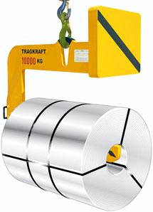


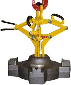


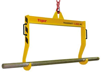


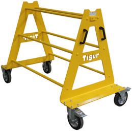


34 Fon +49 (0) Fax +49 (0) Kurschildgen GmbH Hebezeugbau Allgemeine Betriebsanleitung für Lastaufnahmemittel 09 / 2016 Kurschildgen GmbH Hebezeugbau Gustav-Stresemann-Str Bergisch Gladbach, Deutschland
Translation of the Original operating instructions Lifting device Z 70 /...
 Translation of the Original operating instructions Lifting device Z 70 /... Content 1. Lifting device / Correct use according to regulations 2. Basic principles 3. General information 4. Special remarks
Operating Instructions. TM Girder Clamps
 Operating Instructions TM Girder Clamps Original operating instructions in keeping with the EC Machinery Directive TM-BC-10 TM-BC-20 TM-BC-30 TM-BC-50 TM girder clamps meet requirements as per EU Machinery
Crane fork KGM/KGA and KGQ/KGL
 Crane fork KGM/KGA and KGQ/KGL Operating manual This equipment must not be installed, operated or maintained by any person who has not read and understood all the contents of this manual - 1 - Table of
AC 100. Operating instructions Pneumatic Crimper AC 100. Date of issue: 05/2010. Keep for future use!
 Operating instructions Pneumatic Crimper AC 100 Date of issue: 05/2010 Keep for future use! SAFETY SAFETY Basic information The basic prerequisite for ensuring safe use and continuous operation of the
Below the Hook Lifting
 SECTION INDEX S E C T I O N 1 3 BALE LIFTING TONG...-14 BARRIER GRABS...- 14 BEAM TONGS...-14 BEAM, SPREADER Adjustable...-4 Custom...-5 Fiberglass...-4 Fixed...-3 BEAMS, LIFTING Adjustable Hook...-1 Custom...-5
ASSEMBLY AND OPERATING MANUAL LTW PIPE GRAB TYPE GZ 5,0 t
 manufacturer: LTW Tiefbauvertriebs GmbH Holter Weg 11 D 41836 Hückelhoven-Brachelen phone: +49 (0) 24 62 / 2009 0 fax: +49 (0) 24 62 / 2009 15 e-mail: info@ltw-verbau.de homepage: http:\ \ www.ltw-shoring.com
HST -LS Interlocking device (Translation of Original Manual)
") Installation and Operating Manual for Components HST -LS Interlocking device (Translation of Original Manual) HST-LS Ident.-No.: 10268 HST-LS Ident.-No.: 10269 HST-LS, pictured Ident-Nr. 10269 The image
Installation and Operating Manual for Components HST -LS Interlocking device (Translation of Original Manual) HST-LS Ident.-No.: 10268 HST-LS Ident.-No.: 10269 HST-LS, pictured Ident-Nr. 10269 The image
Provided by: Operating, Maintenance & Parts Manual
 Provided by: www.hoistsdirect.com TB681.qxd 11/29/2004 3:04 PM Page 1 Operating, Maintenance & Parts Manual TB603 Manually Lever Operated Chain Hoist 1100 POUNDS MAXIMUM CAPACITY (500 kg) Follow all instructions
Instructions for Use Plain Trolley ULK Geared Trolley UHK
 Instructions for Use Plain Trolley Geared Trolley Item no. Load-carrying capacity (payload) Weight Trolley widths *special trolley widths* Device dimensions mm H / W / D Minimum curve radius mm -005 0,5
PLATE CLAMPS INSTRUCTION MANUAL
 PLATE CLAMPS INSTRUCTION MANUAL Imported exclusively by Pacific Hoists Pty. Ltd. & Pacific Hoists Ltd. In support of cancer charities in Australia & New Zealand Universal Plate Clamp 1 Horizontal Plate
Fork Protection Products. Fork shoes and equipment for fork lift trucks
 Fork Protection Products Fork shoes and equipment for fork lift trucks Guaranteed performance reduces your risk Reliable operation due to optimised functionality Simple and safe handling up work speeds
TABLE OF CONTENT. 7-Operating mechanisms of Non-return valve with hydraulic damping cylinder
 TABLE OF CONTENT Title 1- Tilting-Disc Non-Return valves with counter weight (NVTW) 2-Parts list 3-Installation Non-return valve and Butterfly Valve 4-Dimensions 5-Installation of Non-return valves with
Adjustable Speaker Mount GRAVIS 8
 Adjustable Speaker Mount GRAVIS 8 User's Manual Translation of the original instructions Important Information, Please Read Before Use! KLING & FREITAG GmbH Junkersstraße 14 D-30179 Hannover TEL +49 (0)
Adjustable Speaker Mount GRAVIS 12
 Adjustable Speaker Mount GRAVIS 12 User's Manual Translation of the original instructions Version 3.3 Released: 19.01.2017 Important Information, Please Read Before Use! KLING & FREITAG GmbH Junkersstraße
Tooling Assistance Center
 Safeguards are designed into this application equipment to protect operators and maintenance personnel from most hazards during equipment operation. However, certain safety precautions must be taken by
BEAM CLAMP INSTRUCTION MANUAL
 BEAM CLAMP INSTRUCTION MANUAL Imported exclusively for the Global Lifting Group by Pacific Hoists Pty. Ltd. & Pacific Hoists Ltd. 2 SAFETY INSTRUCTIONS THE FOLLOWING SAFETY INSTRUCTIONS OUTLINE THE CARE
PLM series Permanent load lifting magnets
 Lifting gear Load lifting magnets/chain hoists PLM series Permanent load lifting magnets Load-bearing capacity of up to 1 t depending on model despite light weight High standard of safety with simple lever
Operating instructions LIFTKET Electric chain hoists
 Operating instructions LIFTKET Electric chain hoists Please do not use the electric chain hoist before all operators have carefully read and understood this manual and signed the form on the rear cover.
OPERATIONS MANUAL LEVER CHAIN HOIST
 OPERATIONS MANUAL LEVER CHAIN HOIST IMPORTANT SAFETY INFORMATION Please read, understand and follow all safety information contained in these instructions prior to the use of this hoist. Retain these instructions
GSM. Modular Design. Versions of the series. Type GSM. Gripper type P Z W R. Size. {} AS IS without O.D. clamping I.D. clamping
 GSM Pneumatic Gripper-Swivel System Modular Design Versions of the series Type GSM Gripper type P Z W R Size 32 40 50 64 30 38 45 16 20 25 32 40 16 20 25 32 40 Gripping force safety device {} AS IS without
ABACO MACHINES OPERATION MANUAL STONE/STEEL/GLASS/WOODS LIFTER (ASSGWL20) ABACO MACHINES (USA)
 ABACO MACHINES (USA)") ABACO MACHINES OPERATION MANUAL STONE/STEEL/GLASS/WOODS LIFTER (ASSGWL20) ABACO MACHINES (USA) 14508 S. Garfield Ave., Paramount, CA 90723, USA Tel : 310-532-0366 Fax : 310-532-99 Email : sales@abacomachines.com
ABACO MACHINES OPERATION MANUAL STONE/STEEL/GLASS/WOODS LIFTER (ASSGWL20) ABACO MACHINES (USA) 14508 S. Garfield Ave., Paramount, CA 90723, USA Tel : 310-532-0366 Fax : 310-532-99 Email : sales@abacomachines.com
INSTRUCTION MANUAL. Pacific Self-locking Beam Trolleys Pacific Adjustable Angle Clamps Pacific Top Girder Clamps
 INSTRUCTION MANUAL Pacific Self-locking Beam Trolleys Pacific Adjustable Angle Clamps Pacific Top Girder Clamps IMPORTANT Please read this instruction manual before using these products. This manual contains
Instruction Manual Crane Fork NOTE:
 Instruction Manual Crane Fork NOTE: OWNER/OPERATER MUST READ AND UNDERSTAND THIS INSTRUCTION MAMUAL BEFORE USING IT. - 0 - 1. GENERAL This manual contains important information for the correct installation,
Operating instructions LIFTKET Electric chain hoists
 Operating instructions LIFTKET Electric chain hoists Please do not use the electric chain hoist before all operators have carefully read and understood this manual and signed the form on the rear cover.
In This Document MODULE DESCRIPTION This module provides information on the safety concerns and
 Crane Safety Fact Sheet In This Document MODULE DESCRIPTION This module provides information on the safety concerns and Introduction necessary precautions you will need to be aware of when working Crane
DESCRIPTION, TECHNICAL SPECIFICATION, OPERATION, AND MAINTENANCE MANUAL FOR THE ISU-SYSTEM INNOVATIVER SATTELANHÄNGER UMSCHLAG
 DESCRIPTION, TECHNICAL SPECIFICATION, OPERATION, AND MAINTENANCE MANUAL FOR THE ISU-SYSTEM INNOVATIVER SATTELANHÄNGER UMSCHLAG INNOVATIVE SEMITRAILER HANDLING UNIT Seite 1 / 27 DESCRIPTION, TECHNICAL SPECIFICATION,
Lifting device for standard removable versions
 Operating manual Lifting device for standard removable versions Type 1889 haacon hilft heben haacon hebetechnik gmbh Josef-Haamann-Str. 6 D-97896 Freudenberg/Main Tel: +49 (0) 93 75/84-0 Fax: +49 (0) 93
Star Swivel-Arm Hoist Installation and Operating Instructions
 Star Swivel-Arm Hoist Installation and Operating Instructions Conveying & Hoisting Solutions P/L ABN 78 6 7. Purpose of Equipment Star Swivel-Arm Hoists are intended for the transport of materials. Star
Owner s Manual. ELECTRIC WIRE ROPE HOIST and TROLLEY RH SERIES
 EFFECTIVE: September 25, 2007 Owner s Manual ELECTRIC WIRE ROPE HOIST and TROLLEY RH SERIES 2 Ton through 20 Ton Capacity Product Code and Serial Number WARNING This equipment should not be installed,
L Standard Parts for Mould Making
 A Die Sets B Precision Ground Plates and Flat Bars C Lifting and Clamping Devices Shanks, Lifter Studs and Lifting Hooks, Eyebolts Clamping Claws, Screws and Bolts D Guide Elements E Ground Precision Components
B Precision Ground Plates and Flat Bars. E Ground Precision Components. G Elastomer-Bars, -Sheets, -Sections
 A Die Sets B Precision Ground Plates and Flat Bars C Lifting and Clamping Devices Shanks, Lifter Studs and Lifting Hooks, Eyebolts Clamping Claws, Screws and Bolts D Guide Elements E Ground Precision Components
Compensation unit AGE-XY 50-80
 Translation of the origninal manual Compensation unit AGE-XY 50-80 Assembly and operating manual Superior Clamping and Gripping Imprint Imprint Copyright: This manual remains the copyrighted property of
Product Information Overspeed governor GB 260
 Product Information GB 260 Copyright as per DIN ISO 16016. Manufactured under licence of C. Haushahn GmbH & Co. I Subject to modification. Published by SLC Sautter Lift Components GmbH & Co. KG Borsigstrasse
Support legs. Installation and operating instructions
 Support legs Installation and operating instructions Table of contents 1 Explanation of symbols... 3 2 Assembly... 4 3 Operation... 5 4 Servicing and testing... 8 2 MUB 013 001 M01 (REV--) 11/2016 Support
M MODEL FORK POSITIONERS
 Index: INTRODUCTION SPECIFICATIONS AND USE OF THE EQUIPMENT 1. RECOMMENDATIONS FOR USING THE EQUIPMENT 1.1 PROHIBITED MOVEMENTS 1.2 CORRECT MOVEMENTS 2. ATTACHMENT CONFIGURATION 3.INSTALLING THE POSITIONER
Mounting Tools 2 Checking Clearances 3 Components 4-5 Mounting 6-21 Correct Method of Tensioning the Chain 22 Adjusting The Overall Dimension 23-24
 Mounting Tools 2 Checking Clearances 3 Components 4-5 Mounting 6-21 Correct Method of Tensioning the Chain 22 Adjusting The Overall Dimension 23-24 Maintenance 25 Repairing Main Body Patterns 26 Removal
Operating instructions Actuator and Emergency exit AZ/AZM 200-B30 AZ/AZM 201-B About this document. Content
 1. About this document Operating instructions............pages 1 to 10 Original 1.1 Function This operating instructions manual provides all the information you need for the mounting, set-up and commissioning
Lifting Points Rotating Ball-bearing De-centered Weldable Screw-on
 ifting Points Rotating Ball-bearing De-centered Weldable Screw-on ifting Points ifting Points Information 3:2 Rotating Eye ifting Point - REP 3:4 Rotating ifting Point - RP 3:5 Decentered ifting Point
Owner s Manual Gantry Cranes
 Owner s Manual Gantry Cranes Fixed Height Gantry Crane MODEL NUMBER: SERIAL NUMBER: CAPACITY IN TONS: Telescoping Gantry Crane Bushman Equipment, Inc. 262-790-4200, 800338-7810, Fax 262-790-4200 www.bushman.com
Operating instructions
 Operating instructions Digital tank contents indicator DTA 10 DTA 10 DTA 10 0 4.0 m fuel oil 0 3.5 m water Read instructions before using device! Observe all safety information! Keep instructions for future
Tiger Lifting Home of the Tiger hoisting range & Tiger subsea lifting products
 Tiger Lever Hoist Model No PROLH (with overload protection) Main Features Now available with slipping clutch overload protection Range 750kg - 10.0t Equipped with our unique dual brake mechanism New twin
Tiger Lifting Home of the Tiger hoisting, winching and height safety ranges
 Tiger Corrosion Resistant Chain Block Model No. SS12 with clevis adaptor and shackle Spark resistant option Main Features Suitable for use in multi-immersion applications DNV GL Verification tested according
Mounting and Operating Instructions EB EN. Type 3271 and Type 3277 Pneumatic Actuators. Actuator areas: 175v2, 350v2, and 750v2 cm²
 Type 3271 and Type 3277 Pneumatic Actuators Actuator areas: 175v2, 350v2, and 750v2 cm² Translation of original instructions Type 3271 (left) and Type 3277 (right) Pneumatic Actuators Mounting and Operating
Type 3571 Pneumatic Actuator. Actuator areas: 27 in² 54 in² 116 in². Original instructions. Mounting and Operating Instructions EB 8820 EN
 Type 3571 Pneumatic Actuator Actuator areas: 27 in² 54 in² 116 in² Original instructions Mounting and Operating Instructions Edition April 2016 Note on these mounting and operating instructions These mounting
Assembly Instructions
 Drive Technology \ Drive Automation \ System Integration \ Services *2450452_0617* Assembly Instructions Didactics - Gear Unit Technology Helical Gear Unit R57F AD2 Edition 06/2017 2450452/EN SEW-EURODRIVE
2-finger parallel gripper GM
 Translation of the Original operating manual 2-finger parallel gripper GM 80-201 Assembly and Operating Manual Superior Clamping and Gripping Imprint Imprint Copyright: This manual remains the copyrighted
Cranes. OSHA Office of Training & Education 1
 Cranes OSHA Office of Training & Education 1 Major Causes of Crane Accidents Contact with power lines Overturns Falls Mechanical failures OSHA Office of Training & Education 2 How Do Accidents Occur? Instability
OPERATION AND PARTS MANUAL
 OPERATION AND PARTS MANUAL MODEL NUMBER : PART NUMBER : GTL 1110 1900-0510 SERIAL NUMBER : BAYNE MACHINE WORKS, INC. PHONE: (864) 288-3877 910 FORK SHOALS ROAD TOLL FREE: (800) 535-2671 GREENVILLE S.C.,
Mechanical Operating Instructions
 Mechanical Operating Instructions SE 5.24 WS / SE 5.24 51172095 / 04.2006 Bau muster Zertifizierung geprüft EN 13241-1 OPERATING INSTRUCTIONS 52210111 consisting of: M : Mechanical Operating Instructions
Installation and Operating Instructions for EAS -NC clutch Type 45_. _. _ Sizes 02 and 03
 Table of contents: Please read and observe this Operating Instruction carefully! A possible malfunction or failure of the clutch and any damage may be caused by not observing it. Page 1: - Table of contents
RTC 8050 Series II. 50 ton (45.36 metric tons) Telescopic Boom Rough Terrain Crane
 Telescopic Boom Rough Terrain Crane") Telescopic Boom Rough Terrain Crane RTC 85 Series II 5 ton (45.36 metric tons) Boom and Fly Capacities for this machine are listed by the following sections. Working Range Diagram 35.5 to 6.3 (1.82 18.38
Telescopic Boom Rough Terrain Crane RTC 85 Series II 5 ton (45.36 metric tons) Boom and Fly Capacities for this machine are listed by the following sections. Working Range Diagram 35.5 to 6.3 (1.82 18.38
HitchHoist Assembly & Operating Instructions IMPORTANT NOTICE
 HitchHoist Assembly & Operating Instructions IMPORTANT NOTICE FAILURE TO READ AND COMPLY WITH THE INSTRUCTIONS PRINTED IN THIS MANUAL COULD RESULT IN SERIOUS INJURY! IT IS STRONGLY RECOMMENDED THAT PERSONNEL
ATTACHMENTS FOR LOADER CRANES
 ATTACHMENTS FOR LOADER CRANES 2012 Rotators page KM 03 S Rotator with shaft 11 KM 04 S Rotator with shaft 11 KM 04 F Rotator with flange 11 KM 06 F Rotator with flange 12 Brick Stack Grapples KM 332V-1100
JSK 34. Installation and operating instructions
 JSK 34 EN Installation and operating instructions Table of contents 1 Explanation of symbols... 3 2 Safety information... 4 2.1 Safety information for operation... 4 2.2 Safety information for installation...
4 B High Do not allow anyone except the signal person in the working area
 LOADING OPERATIONS Always operate the mast and forks from the operator's seat Be careful not to operate the lever by mistake. There is danger that the forks or work equipment may cause serious injury Unauthorised
Mounting and Operating Instructions EB 8097 EN. Type and Type Pneumatic Control Valves
 Type 3347-1 and Type 3347-7 Pneumatic Control Valves Type 3347-7, cast body with welding ends Type 3347-7, bar stock body with threaded connections Mounting and Operating Instructions EB 8097 EN Edition
MATERIALS HANDLING MATERIALS HANDLING
 7 MATERIALS HANDLING SPREADER BAR END CAPS & EQUALISERS...142 SPREADER BARS...143 CONTAINER LIFTERS 20 & 40FT...144 PERSONNEL WORK CAGES...145 LOAD ROLLERS & LOAD SKATES...146 HAND PALLET TRUCK & LIFTING
ELECTRIC CHAIN HOIST. O p e r a t i n g i n s t r u c t i o n s. Issue April 2011
 Issue April 2011 ELECTRIC CHAIN HOIST O p e r a t i n g i n s t r u c t i o n s - Original - Please do not use the electric chain hoist before all operators have carefully read and understood this manual
Support T10552 T10595 T40386
 T10552 T10595 T40386 en-gb 7 T10552 T10595... 1 General Information Product name: Product type: Product number: Weight: Max. load capacity: Static test coefficient: 3.0 Intended Use: Load holding device
Pneumatic or Electropneumatic Positioner for Rotary Actuators Type Fig. 1 Type 3761 Positioner. Mounting and Operating Instructions EB 8386 EN
 Pneumatic or Electropneumatic Positioner for Rotary Actuators Type 3761 Fig. 1 Type 3761 Positioner Mounting and Operating Instructions EB 8386 EN Edition June 2004 Contents Contents Page 1 Design and
General Instructions and Inspection Instructions for Crane
 General Instructions General Instructions and Inspection Instructions for Crane Distributed by Ergonomic Partners Sales@ErgonomicPartners.com www.ergonomicpartners.com Tel: 314-884-8884 EN R_(EN)/1 --
ISO INTERNATIONAL STANDARD. Bi-directional and multi-directional fork-lift trucks Stability tests
 INTERNATIONAL STANDARD ISO 15794 First edition 2001-02-15 Bi-directional and multi-directional fork-lift trucks Stability tests Chariots élévateurs à fourche bi-directionnelle et multi-directionnelle Essais
Rev. 10/27/2015 CDL-2000, MANUAL
 VESTIL MANUFACTURING CORP. 2999 North Wayne Street, P.O. Box 507, Angola, IN 46703 Telephone: (260) 665-7586 Toll Free (800) 348-0868 Fax: (260) 665-1339 www.vestilmfg.com e-mail: sales@vestil.com CDL-2000
Ground bearing pressure 1.1 kg/cm 2 2 HS 855 HD
 The operating weight includes the basic machine with HD undercarriage, 2 main winches 250 kn including wire ropes (90 m) and 18 m main boom, 2x hose reels (1 m), each with 120 m of hydraulic hose, consisting
Trolleys and beam clamps
 32 Trolleys and beam clamps Trolleys and beam clamps Yale trolleys and beam clamps can be supplied in many different designs and are used to support and mount hoisting equipment for fixed or traversing
Spring hangers, spring supports
 Spring hangers, spring supports 2 spring Spring hangers, supports PRODUCT 2 GROUP Spring hangers, spring supports Contents Page Field of application...2.1 Overview of spring hangers and spring supports...2.3
HELM Hardware for Sliding Gates. Sliding hardware
 HELM Hardware for Sliding Gates Sliding hardware HELM Hardware for Sliding Gates Contents General Information General Information Page 3 Hardware for Sliding Gates General Information, HELM 00 - HELM 700
BUTTERFLY VALVE WITH WELDED ENDS INSTALLATION AND MAINTENANCE MANUAL
 BUTTERFLY VALVE 31300 SERIES INSTRUCTIONS FOR INSTALLATION, USE AND MAINTENANCE 1. Overview Read these instructions carefully before starting the valve installation and start-up work. Safe keep the instructions
ABACO GLASS LIFTER (AGL38)
") ABACO MACHINES ABACO GLASS LIFTER (AGL38) ABACO MACHINES (USA) 14508 S. Garfield Ave., Paramount, CA 90723, USA Tel : 310-532-0366 Fax : 310-532-0499 Email : sales@abacomachines.com Website : www.abacomachines.com
ABACO MACHINES ABACO GLASS LIFTER (AGL38) ABACO MACHINES (USA) 14508 S. Garfield Ave., Paramount, CA 90723, USA Tel : 310-532-0366 Fax : 310-532-0499 Email : sales@abacomachines.com Website : www.abacomachines.com
ELECTRIC LIFTER TROLLEY INSTRUCTION MANUAL
 ELECTRIC LIFTER TROLLEY INSTRUCTION MANUAL Imported exclusively by Pacific Hoists Pty. Ltd. & Pacific Hoists Ltd. In support of cancer charities in Australia & New Zealand 2 www.jbstools.com WWW.CHALLENGERHOISTS.COM.AU
Bowl feeder WV401-1 / Translation of operating and installation instructions
 Bowl feeder WV401-1 / 402-1 Translation of operating and installation instructions Copyright by Afag GmbH This operation instruction applies to: Bowl feeder WV401-1 Bowl feeder WV402-1 Type 230 V / 50
MS2200, MS2500, and MS3000 Suspension Installation Manual ON/OFF HIGHWAY SUSPENSION SYSTEM
 MS22, MS25, and MS3 Suspension Installation Manual ON/OFF HIGHWAY SUSPENSION SYSTEM 972.547.62 8.445.736 FAX: 972.542.97 725 E. UNIVERSITY ST. McKINNEY, TEXAS 7569 www.watsonsuspensions.com Watson & Chalin
Operating Manual TWN 0121/1. Lifting point, screw-type TWN 0122 TWN 0123 TWN 0127 TWN 1120 TWN 1830 TWN 1890
 TWN 0121/1 Operating Manual Lifting point, screw-type TWN 0122 TWN 0123 TWN 0127 TWN 1120 TWN 1830 TWN 1890 THIELE GmbH & Co. KG Werkstraße 3 Tel: +49 (0)2371 / 947-0 58640 Iserlohn www.thiele.de B07905-D
Before equipment use, please read this operation manual carefully. Serial Number: Date Purchased:
 Pushed & Geared Trolleys OPERATION MANUAL This operation manual is intended as an instruction manual for trained personnel who are in charge of installation, maintenance, repair etc. Before equipment use,
Drive Unit e-drive1. Installation instructions 04/2014. English translation of the original German installation instructions
 Drive Unit e-drive1 Installation instructions 04/2014 English translation of the original German installation instructions Contents Foreword... 3 Availability... 3 Structural features in the text... 3
LINK-BELT MODEL HTC-8675LB - 75 TON CAPACITY 48 7" (.80m) 41 0" /8" (3.52m) /16" (2.02m) /4" (.34m) 25" 11 0" (.
 41 0 /8 (3.52m) /16 (2.02m) /4 (.34m) 25 11 0 (.") LIFTING CHARTS - Hydraulic Truck Cranes LINK-BELT MODEL - 75 TON CAPACITY 41 0" (12.50m) 48 7" (14.80m) C L Of Rotation 13 8 1/8" (4.17m) 7 0" (2.13m) 4 5/8" (118mm) 11 6 7/8" (3.52m) 6 7 11/16" (2.02m)
LIFTING CHARTS - Hydraulic Truck Cranes LINK-BELT MODEL - 75 TON CAPACITY 41 0" (12.50m) 48 7" (14.80m) C L Of Rotation 13 8 1/8" (4.17m) 7 0" (2.13m) 4 5/8" (118mm) 11 6 7/8" (3.52m) 6 7 11/16" (2.02m)
Technical data Hydraulic crawler crane HS 875 HD
 Technical data Hydraulic crawler crane HS 875 HD Dimensions Basic machine with undercarriage R 5710 2580 8300 3500 2110 1300 1240 4020 1400 5330 2600 1000 530 6480 2240 4900 R 5520 14100 Operating weight
Polyester Lifting Slings
 Est. 969 Polyester Lifting Slings FASTLIFT Endless Roundsling (ERS) Roundslings with seamless single cover and protected label WLL Colour Weight Rec. min Rec. min Standard size range available (tonnes)
Turbocharger / A100-L Original assembly instructions English
 Assembly Instructions Turbocharger / A100-L Original assembly instructions English This document is valid for the A100-L series: A165-L, A170-L, A175-L, A180-L, A185-L, A190-L Purpose The assembly instructions
Product Information. Long-stroke gripper PHL 32
 Product Information PHL 32 PHL Flexible. Precise. Powerful. PHL long-stroke gripper 2-finger parallel gripper with large jaw stroke for large parts and / or a broad range of parts Field of application
Coil Lifters and Upenders
 Model 82-NC Narrow Coil C Hook Handles narrow coils with less coil edge damage. More durable than web slings. Light weight for easier handling. Built in guide handle for ease of coil positioning. Available
CRANE RATING MANUAL HTC
 SERIAL NUMBER: CRANE RATING MANUAL 5---Section Boom For Replacement, Order Part Number: N3P0199 (031907) R Link-Belt is a registered trademark. 1of244 N3P0200 Table Of Contents Page Contents 3---4 Operating
Technical data Hydraulic crawler crane HS 895 HD
 Technical data Hydraulic crawler crane HS 895 HD Dimensions Basic machine with undercarriage R 9760 3650 10000 5480 3675 2445 1810 3950 1610 1700 7945 9360 3975 1720 R 6360 1100 6800 620 17380 Operating
Working Instructions Translation
 WIDOS Einsteinstr. 5 Phone +49 (0) 71 52 99 39-0 W. Dommer Söhne GmbH D-71254 Ditzingen-Heimerdingen Fax +49 (0) 71 52 99 39-40 Website: www.widos.de Email: info@widos.de Working Instructions Translation
Table of contents. Tigrip Load Hoisting Tackle. Tigrip Crane Weighers INFO. Page. Grabs & Clamps
 TIGRIP 143 Tigrip Load Hoisting Tackle Table of contents Page Lifting clamps and attachments have a reputation for reliability, quality and safety going back more than 35 years. For transportation and
Crane Forks. Introduction. Important Notes. Key Benefits. User Guide
 User Guide Crane Forks Introduction Fully self levelling, even when unloaded, Conquip Crane Forks have been designed to lift packs of bricks and pallets. The crane attachment has adjustable forks and a
Mounting and Operating Instructions EB EN. Type 3271 Pneumatic Actuator. Actuator area: 1000 cm². Translation of original instructions
 Type 3271 Pneumatic Actuator Actuator area: 1000 cm² Translation of original instructions Type 3271 Pneumatic Actuator Mounting and Operating Instructions Edition April 2018 Note on these mounting and
Operating Instructions for Elevator Buffers type LP
 Operating Instructions for Elevator Buffers type LP 1 Scope of application The Elevator Buffer type LP is an energy dissipation type buffer according to EN 81-1/2, EN 81-20, EN 81-50 5.5 and therefore
Planar surface gantry EXCM-30. Instructions. Mechanical installation b [ ]
![Planar surface gantry EXCM-30. Instructions. Mechanical installation b [ ]](/thumbs/91/106333591.jpg "Planar surface gantry EXCM-30. Instructions. Mechanical installation b [ ]") Planar surface gantry EXCM-30 Instructions Mechanical installation 804447 605b [8044434] EXCM-30 Translation of the original instructions LOCTITE is a registered trademark of its respective trademark holder
Planar surface gantry EXCM-30 Instructions Mechanical installation 804447 605b [8044434] EXCM-30 Translation of the original instructions LOCTITE is a registered trademark of its respective trademark holder
Tiger Lifting Home of the Tiger hoisting range & Tiger subsea lifting products
 Tiger ROV Chain Block Model No RCB Main Features Available in 3.0t, 10.0t, 15.0t and 20.0t capacity Fully corrosion protected Several choices of interface: o Hydraulic Hot Stab connection type A dual port
Technical data/component parts
 Technical data/component parts Demag pillar and wall-mounted slewing jib cranes 191214 en GB 203 814 44 714 IS 132 Manufacturer Terex MHPS GmbH Forststrasse 16 40597 Düsseldorf, Germany www.demagcranes.com
Operating Instructions LEO 23 GT
 Operating Instructions for Aerial Work Platform LEO 23 GT Machine no. 140671 Technical specifications are subject to change without notification TEUPEN Maschinenbaugesellschaft mbh Place of business: Marie-Curie-Strasse
Operating and Maintenance Manual. for. HADEF overhead crane. as jointed crane TA
 5.52.714.00.1.0 Edition 03.2004 GB Operating and Maintenance Manual for HADEF overhead crane as jointed crane TA Subject to changes. 1 HADEF Table of Contents 1 General Page 3 2 Product description Page
ROTARY MODULES. Rotary modules
 Rotary modules Rotary modules ROTARY MODULES Series Size Page Rotary modules RM swivel unit 156 RM 08 160 RM 10 162 RM 12 164 RM 15 168 RM 21 172 RM rotor 176 RM 50 180 RM 110 182 RM 200 184 RM 310 186
Table of contents. Tigrip Load Hoisting Tackle. Tigrip Crane Weighers INFO. Page. Grabs & Clamps
 TIGRIP 143 Tigrip Load Hoisting Tackle Table of contents Page Lifting clamps and attachments have a reputation for reliability, quality and safety going back more than 35 years. For transportation and
20 TONNE HYDRAULIC PRESS MODEL NO: CSA20FBT
 20 TONNE HYDRAULIC PRESS MODEL NO: CSA20FBT PART NO: 7614058 OPERATION & MAINTENANCE INSTRUCTIONS WARNING: Read these instructions before using the press GC0516 INTRODUCTION Thank you for purchasing this
USE AND MAINTENANCE MANUAL
 CLAMP FOR APPLIANCES ORIGINAL INTRODUCTION This manual contains instructions for assembly, periodic and extraordinary maintenance and troubleshooting. The instructions in this manual supplement, and do
Type 3761 Pneumatic or Electropneumatic Positioner for Rotary Actuators. Fig. 1 Type 3761 Positioner. Mounting and Operating Instructions EB 8386 EN
 Type 3761 Pneumatic or Electropneumatic Positioner for Rotary Actuators Fig. 1 Type 3761 Positioner Mounting and Operating Instructions EB 8386 EN Edition July 2007 Contents Contents Page 1 Design and
Keystone Figure 85/86 Check valves Installation and Maintenance Instructions
 Please read these instructions carefully 1.3 Handling 1.3.1 Packed valves Lifting and handling of the packed valves in crates should be carried out by appropriate lifting equipment. If a fork lift truck
On-A-Roll Lifter Instruction Manual for Standard Models Read Before Use!
 On-A-Roll Lifter Instruction Manual for Standard Models Read Before Use! Important instructional, safety and precautionary information! It is the user s responsibility to exercise good judgment, common