RSA Protective Technologies
|
|
|
- Alvin Taylor
- 6 years ago
- Views:
Transcription


")
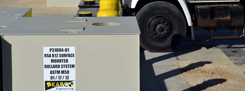
1 TEST REPORT FOR: RSA Protective Technologies K12 Surface Mounted Bollard System TESTED TO: ASTM F Standard Test Method for Vehicle Crash Testing of Perimeter Barriers Test M50 PREPARED FOR: Battelle Memorial Institute 1550 Crystal Drive, Ste 600 Arlington, VA TEST REPORT NUMBER: REPORT DATE: February 13, 2012 TEST DATE: January 18, 2012 KARCO Engineering, LLC. Automotive Research Center 9270 Holly Road Adelanto, CA Tel: (760) Fax: (760)
2 KARCO Engineering compiled this publication for information gathering only. The findings and conclusions expressed in this publication are those of the authors and not necessarily those of any other organization. KARCO Engineering provides test services only and is not involved in consulting, product design or the manufacturing of any automotive products. KARCO does not warrant, supervise or monitor compliance of products or services except as specifically agreed to in writing. By their very nature, testing, analysis and other KARCO services are limited in scope and subject to expected measurement variability. No activity by KARCO Engineering can release a manufacturer from product or any other liability. The results, findings and conclusions expressed in this publication relate only to the items tested for the specific situation simulated in the test. Tested By: Report By: Reviewed By: Approved By: Mr. Kelsey A. Chiu Engineering Department Supervisor Mr. Kelsey A. Chiu Engineering Department Supervisor Mr. Matthew S. Hubbard Quality Assurance Manager Mr. Michael L. Dunlap Director of Operations Approval Date: February 13, 2012 i
3 REVISION CONTROL LOG TR-P Revision Date Description -NC 02/13/12 Original Test Report ii
4 TABLE OF CONTENTS Section Page 1 Introduction 1 2 Test Article Details 6 3 Test Results 7 4 Data Sheets 8 Table Page 1 Test Vehicle Properties 2 2 Penetration Ratings 4 Data Sheet Page 1 Test Vehicle Information 9 2 Test Vehicle Geometry 10 3 Impact Conditions 11 4 Evaluation of Test Results 12 5 Observations 13 6 Sensor Data 14 Appendix Page A Photographs A B Data Plots B C Data Acquisition Information C D Drawings and Illustrations D Final Page of Report D-6 iii
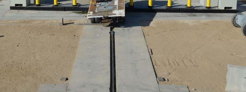
5 SECTION 1 INTRODUCTION 1.1 OBJECTIVES The primary objective of this impact test was to determine a penetration rating for the RSA Protective Technologies K12 Surface Mounted Bollard System (test article) per the ASTM F Standard Test Method for Vehicle Crash Testing of Perimeter Barriers to the M50 level. The intent of this test was to evaluate the ability of the barrier to arrest a 6,800 kg (15,000 lb) vehicle from penetrating or vaulting a secured area and the extent, if any, of barrier deformation. This report presents the results of the performance and evaluation of one (1) full-scale impact test conducted on one (1) RSA K12 Surface Mounted Bollard System to the M50 (80 km/h, 50 mph) level. Testing and reporting of test results are described in the test procedure and are not repeated in this report. 1.2 TEST FACILITY This test was conducted at KARCO Engineering s test facility in Adelanto, California. The tow road is a continuous level surface constructed of reinforced concrete and measures 850 feet in length, is 14 feet wide, and 6 in. thick. A steel rail is embedded in the road to provide vehicle guidance. Vehicle tow propulsion is provided by a 1 ton truck using a 1-to-2 pulley system coupled to a fixed prime mover (an internal combustion engine, Chevrolet V-8, 454 cubic inch displacement, with TH-400 automatic transmission) and continuous cable drive system. The test vehicle is towed to within 25 feet of the barrier by a nylon rope clamped to a 3/8-inch steel cable. The clamp is released from the cable on contact with a cable release mechanism positioned to allow the test vehicle to proceed under its own momentum for a maximum of 25 feet before impacting the barrier. 1.3 TEST PROCEDURE The RSA K12 Surface Mounted Bollard System was tested per ASTM F Standard Test Method for Vehicle Crash Testing of Perimeter Barriers. This ASTM standard contains specific requirements for test article installation, vehicle properties, impact conditions, test instrumentation, and evaluation criterion Test Article Installation The materials, assembly instructions, and physical configuration of the test article are specified in the manufacturer s literature and are not repeated in this test report. Installation of 1
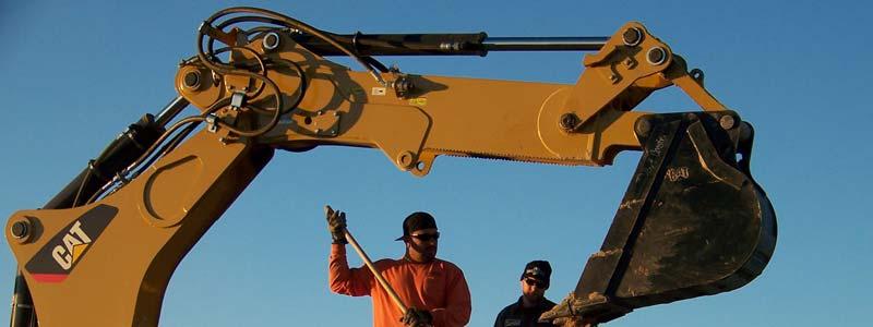
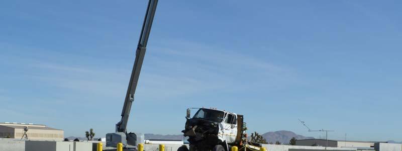
6 the test article was conducted by Desert Construction Services and KARCO Engineering, LLC. The test article, as installed at the test facility, is illustrated in Appendices A and D Test Vehicle Properties ASTM F specifies four (4) different vehicle levels for possible penetration ratings: C (Small Passenger Car), P (Pickup Truck), M (Medium Duty Truck) and H (Heavy Goods Vehicle). All test vehicles must be structurally sound with no major damage or modifications and must have original equipment bumpers. Tire sizes shall be those recommended by the vehicle manufacturer unless otherwise specified by a specific agency. Test Vehicle properties for each vehicle is presented in Table 1. Table 1 Test Vehicle Properties Small Passenger Medium Duty Heavy Goods Pickup Truck Vehicle Type Car Truck Vehicle C P M H Gross Vehicle Test Mass (kg) 1,100 ± 20 2,300 ± 50 6,800 ± ,500 ± 590 Year Within 10 Model Within 10 Model Years Years Wheelbase (m) 5.28 ± 0.51 Bed Length (m) 5.49 ± 0.61 Other Sedan or Coupe 3/4 Ton, Single Cab Flatbed Tandem Axle Dump Truck or Drop Axle Truck This test of the RSA K12 Surface Mounted Bollard System was conducted with the M test vehicle. To meet the recommended properties a commercially available production model test vehicle was selected. This test vehicle was a 1988 GMC Topkick 7000 medium duty truck with conventional cab, front mounted diesel engine, rear wheel drive, and an automatic transmission. The bumpers were standard equipment and were not modified Test Mass: The Gross Vehicle Test Mass of the M test vehicle as specified in the ASTM standard is 6,800 kg ± 140 kg. The actual Gross Vehicle Test Mass with instrumentation and ballast was kg Impact Conditions ASTM F has specific requirements for impact conditions for a qualifying test which include vehicle impact velocity, approach angle and impact location. 2
7 Velocity: Vehicle velocity at impact with the test article shall be dependent upon the test vehicle mass. For this test, designated M50, the target kinetic energy was 1,680 kj. The calculated target velocity was 80.7 km/h (50.2 mph). Actual velocity at impact was 76.8 km/h (47.7 mph) Approach Angle and Impact Point: The test vehicle was oriented so it approached the test article at a critical impact angle of ninety degrees (90 ± 3 ) relative to the barrier, with the centerline of the vehicle impacting the test article at the impact point designated by the client. The actual impact point must be within ± 300 mm (1 ft.) of the target. The impact point was selected to align the vehicle centerline with the center of one (1) individual bollard. The vehicle s centerline intersected the center of the number 6 bollard. The aligned bollard was immediately to the left of the installation centerline. The actual point of impact was perpendicular within 0.5 and within 51 mm (2.0 in.) of the target Test Instrumentation and Data Acquisition Procedures All data acquisition for this test of the RSA K12 Surface Mounted Bollard System was performed in accordance with the ASTM F Standard Test Method requirements Test Vehicle Instrumentation: The test vehicle was instrumented with two (2) tri-axial accelerometers. One (1) was located along the driver s side frame rail at the longitudinal center of mass and the other at the rear of the same frame rail. The accelerometers measured longitudinal (x), lateral (y), and vertical (z) acceleration. Data was recorded using the on-board TDAS. Data was linked to a personal computer and processed using the TDAS Control software. All equipment used in this test meets the requirements of SAE J Calibration: All instrumentation used in this test has been calibrated through standards traceable to NIST and is maintained in a calibrated condition TDAS Software: The software utilized in this system is written in National Instruments Lab Windows/CVI (C, Visual Interface) programming language, which is a Windows based software package with emphasis on ease of use and good engineering test practices SAE Compatibility: The software contains standard point and click processing options for selecting Society of Automotive Engineers (SAE) class post filters and calculating the required integrals, resultants, Head Injury Criteria (HIC), clips, and other data processing parameters that may be required Photographic Documentation: Photographic documentation of this test included a minimum of two (2) real-time video cameras at 30 frames per second (fps), and four (4) highspeed color digital video cameras at 1,000 fps. All high-speed cameras were activated by a pressure-sensitive tape switch which was positioned on the test article to indicate the instant of 3
8 contact (time zero). A digital still camera was used for documenting the pre- and post-test condition of the test article and the test vehicle Measurement Uncertainty: Measurement uncertainties have been determined for pertinent values affecting the results of this test. KARCO maintains these uncertainty budgets, which are available upon request, but are not included in this report. In certain cases the nature of the test method may preclude rigorous and statistically valid calculation of uncertainty of measurement. In these cases KARCO attempts to identify the components of uncertainty and make a reasonable estimation. Reasonable estimation is based on knowledge of the performance of the method and on the measurement scope and makes use of, for example, previous experience and validation data. 1.4 EVALUATION CRITERION This full scale impact test was performed to evaluate the RSA K12 Surface Mounted Bollard System per the specifications of ASTM F Test articles are evaluated for and given a penetration rating. Table 2 Penetration Ratings Measured Penetration Rating Less than 1 m P m m P m P3 Greater than 30 m P Penetration Rating A penetration rating per ASTM F is given to each test article. The measurements used to formulate this rating are taken from penetration reference points on the test vehicle and the test article. The test vehicle reference points are defined in ASTM F as follows: for small passenger cars the reference point is the center of the base of the A-Pillar; for the remaining three test vehicles (Pickup Truck, Medium Duty Truck, and Heavy Goods Vehicle) the reference point is the lower leading edge of the cargo bed. The penetration reference point on the test article varies depending on the type of test article. Several examples are outlined in Annex A1 of ASTM F For this evaluation of the RSA K12 Surface Mounted Bollard System the test article penetration reference point is the vertical plane created by the back (non-impacted) side of the bollards. 4
9 Penetration measurements are taken in both static and dynamic modes. The static penetration measurement is based on the vehicle s final resting position and the dynamic penetration is measured from high speed video. The highest value of both static and dynamic penetration for both the left and right sides of the test vehicle is used to assess the penetration rating. Penetration limits are presented in Table 2. For a test article to be given a penetration rating per ASTM F , the test article must disable the test vehicle to prevent the vehicle from propelling itself forward. If a test article does not sufficiently disable the vehicle it will be considered unrated. 5
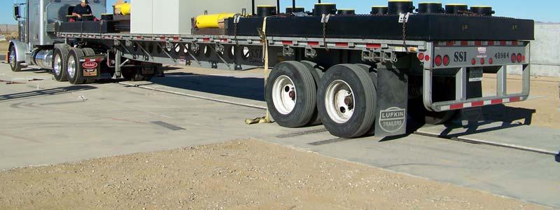
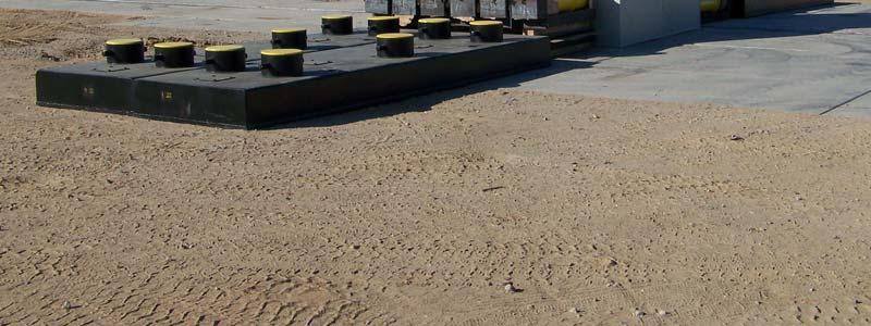
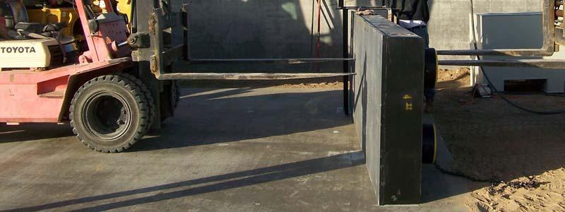
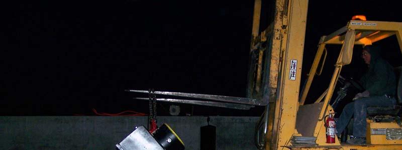
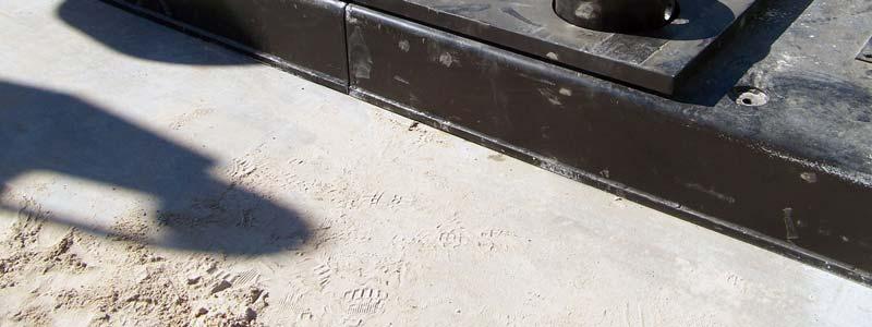
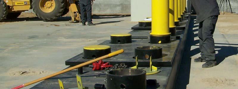
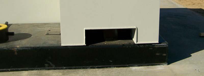
10 SECTION 2 TEST ARTICLE DETAILS 2.1 TEST ARTICLE The RSA Protective Technologies K12 Surface Mounted Bollard System is a twelve (12) fixed, portable bollard array. The array consists of five (5) types of components: base blocks, bollards, connection plates, type I end blocks and type II end blocks. The as-tested installation consists of four (4) bases, twelve (12) bollards, three (3) connection plates, two (2) type I end blocks and two (2) type II end blocks. The base blocks and type I and II end blocks are filled with sand to ballast the unit. The sand is specified to be a minimum of 1602 kg/m 3 (100 lbs/ft 3 ). The complete installation measures 17.9 m (58.7 ft.) wide from end to end. Each base block is constructed of steel and measures 4.5 m (14.7 ft.) wide and 1.2 m (4.0 ft.) long. The main steel body is 0.3 m (1.0 ft.) tall. The base block has provisions to mount three (3) individual bollards, as well as two (2) additional mounts for the connection plate. The base block has three (3) concrete filled portions, aligned with each of the bollards, and four (4) hollow sections used for ballasting. The bollards are constructed of steel tubes and stiffeners. The main steel tube measures 0.3 m (0.9 ft.) diameter, 25 mm (1.0 in.) wall thickness, and is 1.1 m (3.6 ft.) tall. The stiffener plate is 1.2 m (45.9 in.) long and 25 mm (1.0 in.) thick. Each bollard has two tubes welded laterally internally which allow pins to be placed through the bollard. Each bollard is secured to the base block with a 38 mm (1.5 in.) steel pin. The bollards are concrete filled. The connection plates are used to connect individual base blocks in the array. They are constructed of a steel plate measuring 2.1 m (6.9 ft.) wide by 1.2 m (3.9 ft.) long by 50 mm (2.0 in.) thick. They have four 0.3 m (1.1 ft.) diameter holes which connect to adjacent base blocks. One type I end block is placed behind the installation at each end of the array. The block sits on the road surface directly behind the base end base block. Each type I block measures 1.2 m (4.0 ft.) long, 2.4 m (8.0 ft.) wide, and 1.4 m (4.7 ft.) tall. The block is filled with sand to ballast the installation. The type II end block is used to ballast each end of the array. The type II end block mounts over the last bollard and sits on top of the base block. Each block measures 1.2 m (4.0 ft.) long, 1.2 m (4.0) ft wide, and 1.1 m (3.7 ft.) tall. The block is filled with sand to ballast the installation. The as-tested test article varied from the manufacturer drawings in the following ways: A second set of fill holes was added to the top of each base block. The holes were the same diameter as the rear fill holes and located along the lateral centerline of the block, aligned to the rear fill holes. 6
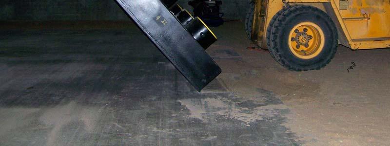
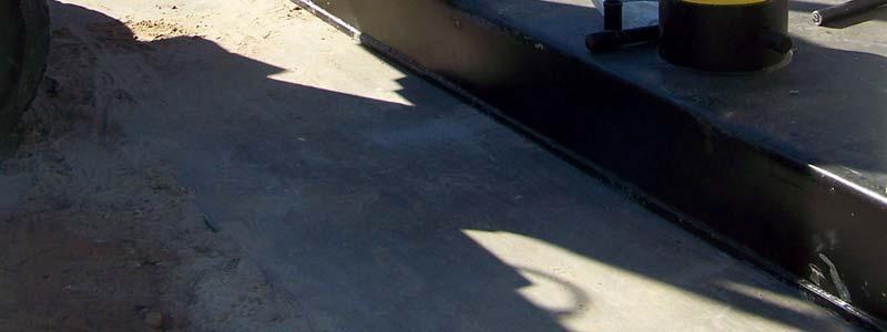
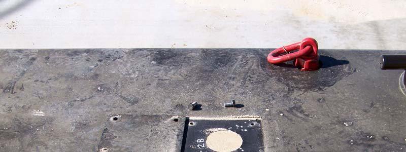
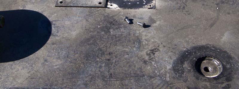
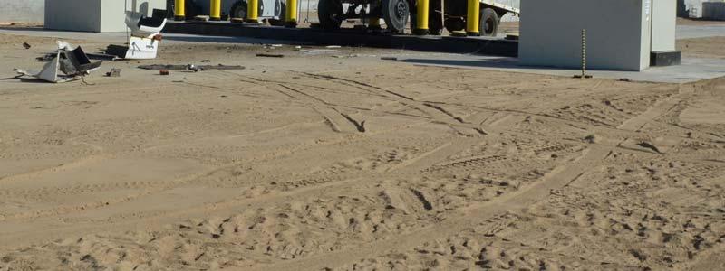
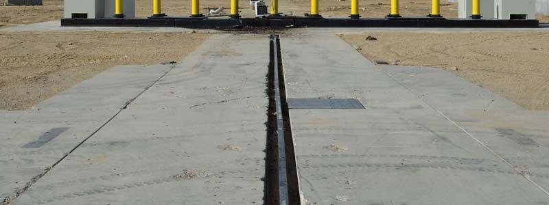
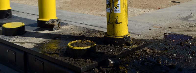
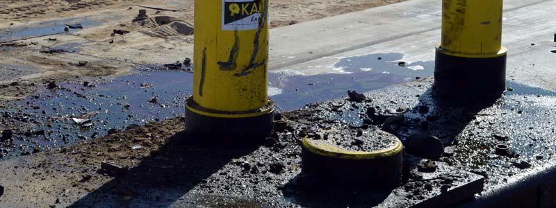
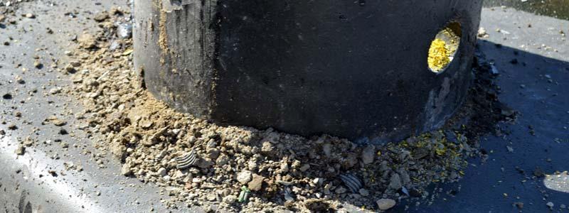
11 SECTION 3 TEST RESULTS 3.1 TEST RESULTS As recommended in ASTM F Standard Test Method for Vehicle Crash Testing of Perimeter Barriers the following full-scale impact test was conducted to evaluate the impact performance of the RSA K12 Surface Mounted Bollard System to the M50 test level. Test M50 was conducted on the RSA K12 Surface Mounted Bollard System on January 18, The test article was positioned at an angle of ninety degrees (90 ) to the direction of travel of the test vehicle, with the vehicle s centerline intersecting the center of the number 6 bollard. The test was conducted using a commercially available 1988 GMC Topkick 7000 medium duty truck with a test inertial mass of kg. Test vehicle information is presented in Data Sheets No. 1 and No. 2. The test vehicle impacted the test article at a velocity of 76.8 km/h (47.7 mph). Evaluation of the test article performance is presented in Data Sheet No. 5. This crash was documented by a minimum of two (2) real-time video cameras and four (4) high-speed digital color video cameras. Photographs of the test vehicle and the K12 Surface Mounted Bollard System are shown in Appendix A. Data plots of the instrumentation are available in Appendix B. The test vehicle s forward motion was completely arrested by the RSA K12 Surface Mounted Bollard System within the 1.0 m penetration limit for a P1 rating. The maximum penetration recorded was m on the driver s side, measured dynamically using high speed video analysis. The maximum penetration on the passenger s side was m measured dynamically using high speed video analysis. The test vehicle was propelled upward and came to rest on top of the impacted bollard. The entire test installation slid rearward on the concrete pad that it was sitting on; the left end moved 2.0 m (6.7 ft.) rearward; the right end moved 1.0 m (3.4 ft.). The type I end blocks slid rearward approximately 2.6 m (8.5 ft.) on the left and 2.0 m (6.7 ft.) on the right side. The type II end blocks remained on the end base blocks. The test article sustained minor damage on the impacted bollard, base block and connection plate between base blocks 2 and 3. The test vehicle sustained severe damage and was completely disabled by the impact. The vehicle s drivetrain and chassis suffered severe damage, and the front axle separated from the vehicle. 7
12 SECTION 4 DATA SHEETS Test Article: RSA Protective Technologies K12 Surface Mounted Bollard System Test Program: ASTM F M50 Project No.: P Test Vehicle: 1988 GMC Topkick 7000 Test Date: 1/18/12 CONVERSION FACTORS Quantity Typical Application Std Units Metric Unit Multiply By Mass Vehicle Weight lb kg Linear Velocity Impact Velocity miles/hr km/hr Length or Distance Measurements in mm 25.4 Volume Fuel Systems gal liter Volume Small Fluids oz ml Pressure Tire Pressures lbf/in 2 kpa Temperature General Use o F o C =(Tf -32)/1.8 Force Dynamic Forces lbf N Moment Torque lbf-ft N m
13 DATA SHEET 1 TEST VEHICLE INFORMATION Test Article: RSA Protective Technologies K12 Surface Mounted Bollard System Test Program: ASTM F M50 Project No.: P Test Vehicle: 1988 GMC Topkick 7000 Test Date: 1/18/12 TEST VEHICLE INFORMATION Make GMC Cylinders V-8 Model Topkick 7000 Engine Displacement (L) Unknown Body Style Medium Duty Truck Engine Placement Longitudinal VIN 1GDM7D1Y6JV Fuel Type Diesel Color White No. of Axles 2 Odometer Reading (mi) 7,028 Disc Brakes, Front No Transmission 5-Speed Automatic Disc Brakes, Rear No Final Drive Rear Anti-Lock Brakes No TIRE INFORMATION Front Tire Size 10R20 Rear Tire Size 10R20 TEST VEHICLE MASS As Received (kg) As Tested (kg) Front Rear Total Front Rear Total Left 1, , , , , ,301.0 Right 1, , , , , ,380.0 Ratio (%) Total 2, , , , , ,
14 DATA SHEET 2 TEST VEHICLE GEOMETRY Test Article: RSA Protective Technologies K12 Surface Mounted Bollard System Test Program: ASTM F M50 Project No.: P Test Vehicle: 1988 GMC Topkick 7000 Test Date: 1/18/12 TEST VEHICLE GEOMETRY No. mm in. No. mm in. No. mm in. A G N 1, B H 1, O C I P 2, D 1, J 1, Q 7, E 2, K 2, F 1, L 2, All measurements in millimeters (mm). Left side measurements reported. 10
15 DATA SHEET 3 IMPACT CONDITIONS Test Article: RSA Protective Technologies K12 Surface Mounted Bollard System Test Program: ASTM F M50 Project No.: P Test Vehicle: 1988 GMC Topkick 7000 Test Date: 1/18/12 IMPACT CONDITIONS Item Value Test Time 9:30 AM Temperature ( F) 55 Wind Velocity (km/h) 0 Wind Direction - Impact Speed (km/h) 76.8 Impact Angle ( ) 89.9 Impact Location (mm) 11 (left) Impact Angle and impact location measured using high speed video analysis 1 - Information for reference only. 11
16 DATA SHEET 4 EVALUATION OF TEST RESULTS Test Article: RSA Protective Technologies K12 Surface Mounted Bollard System Test Program: ASTM F M50 Project No.: P Test Vehicle: 1988 GMC Topkick 7000 Test Date: 1/18/12 PENETRATION RATINGS Measured Penetration Rating Less than 1 m P m m P m P3 Greater than 30 m P4 MEASURED PENETRATION Description Units Value Driver's Side Penetration (Dynamic) m 0.91 Passenger's Side Penetration (Dynamic) m 0.71 Maximum Dynamic Penetration m 0.91 Driver's Side Penetration (Static) m 0.87 Passenger's Side Penetration (Static) m 0.70 Maximum Static Penetration m 0.87 Maximum Penetration m 0.91 PENETRATION RATING ASTM F penetration rating for test P Comments: P1 The K12 Surface Mounted Bollard System completely arrested the test vehicle within the 1.0 m penetration limit for a P1 rating. The test vehicle was completely disabled by the impact. The drivetrain and chassis were severely damaged, and the front axle separated from the vehicle. 12
17 DATA SHEET 5 OBSERVATIONS Test Article: RSA Protective Technologies K12 Surface Mounted Bollard System Test Program: ASTM F M50 Project No.: P Test Vehicle: 1988 GMC Topkick 7000 Test Date: 1/18/12 TEST ARTICLE COMPONENT MASS Description Mass (kg) Individual Quantity Total 1 Base Block 4, ,524 Bollard ,368 Connection Plate ,535 Type 1 End Block 2, ,394 Type 2 End Block 5, ,330 Total 40,151 UNPROTECTED SIDE BOLLARD ANGLE MEASUREMENTS Description Angle ( ) Pre-Test Post-Test Difference Bollard 1 Bollard Bollard Bollard Bollard Bollard Bollard Bollard Bollard Bollard Bollard Bollard Total mass for number of components and the total array are estimated based on the measurement of one of each of the different pieces. 2 Bollard 1 and 12 were not measured because they were inside the Type I end blocks. 13
18 DATA SHEET 5 (CONTINUED) OBSERVATIONS Test Article: RSA Protective Technologies K12 Surface Mounted Bollard System Test Program: ASTM F M50 Project No.: P Test Vehicle: 1988 GMC Topkick 7000 Test Date: 1/18/12 RIGHT SIDE BOLLARD ANGLE MEASUREMENTS Description Angle ( ) Pre-Test Post-Test Difference Bollard 1 Bollard Bollard Bollard Bollard Bollard Bollard Bollard Bollard Bollard Bollard Bollard Bollard 1 and 12 were not measured because they were inside the Type I end blocks. 14
19 DATA SHEET 6 SENSOR DATA Test Article: RSA Protective Technologies K12 Surface Mounted Bollard System Test Program: ASTM F M50 Project No.: P Test Vehicle: 1988 GMC Topkick 7000 Test Date: 1/18/12 TEST VEHICLE ACCELERATION PEAK DATA Location Axis Vehicle Max (g) Time (ms) Min (g) Time (ms) CG X CG Y CG Z CG Resultant N/A Rear Frame Member X Rear Frame Member Y Rear Frame Member Z Rear Frame Member Resultant N/A
20 APPENDIX A PHOTOGRAPHS A
21 LIST OF PHOTOGRAPHS Figure Page 1 Test Article, As-Received A-1 2 Test Article, As-Received A-1 3 Test Article Installation A-2 4 Test Article Installation A-2 5 Test Article Installation A-3 6 Test Article Installation A-3 7 Test Article Installation A-4 8 Test Article Installation A-4 9 Test Article Installation A-5 10 Test Article Installation A-5 11 Test Article Installation A-6 12 Test Article Installation A-6 13 Test Setup A-7 14 Test Setup Close-Up A-7 15 Test Setup A-8 16 Test Setup Close-Up A-8 17 Test Setup A-9 18 Test Setup Close-Up A-9 19 Test Setup A Test Setup Close-Up A Test Setup A Post-Test A Post-Test A Post-Test A Test Article, Pre-Test Front A Test Article, Post-Test Front A Test Article, Pre-Test Left Front ¾ A Test Article, Post -Test Left Front ¾ A Test Article, Pre-Test Left Side A Test Article, Post-Test Left Side A Test Article, Pre-Test Left Rear ¾ A Test Article, Post-Test Left Rear ¾ A-16 A-i
22 LIST OF PHOTOGRAPHS (CONTINUED) Figure Page 33 Test Article, Pre-Test Rear A Test Article, Post-Test Rear A Test Article, Pre-Test Right Rear ¾ A Test Article, Post-Test Right Rear ¾ A Test Article, Pre-Test Right Side A Test Article, Post-Test Right Side A Test Article, Pre-Test Right Front ¾ A Test Article, Post-Test Right Front ¾ A Test Article, Post-Test Damage A Test Article, Post-Test Damage A Test Article, Post-Test Damage A Test Article, Post-Test Damage A Test Article, Post-Test Damage A Test Article, Post-Test Damage A Test Article, Post-Test Damage A Test Article, Post-Test Damage A Test Article, Post-Test Damage A Test Vehicle, Pre-Test Left Front ¾ A Test Vehicle, Post-Test Left Front ¾ A Test Vehicle Manufacturer s Label A Test Vehicle Manufacturer s Label A-27 A-ii


23 FIGURE 1. Test Article, As-Received FIGURE 2. Test Article, As-Received A-1

24 FIGURE 3. Test Article Installation FIGURE 4. Test Article Installation A-2

25 FIGURE 5. Test Article Installation FIGURE 6. Test Article Installation A-3


26 FIGURE 7. Test Article Installation FIGURE 8. Test Article Installation A-4


27 FIGURE 9. Test Article Installation FIGURE 10. Test Article Installation A-5


28 FIGURE 11. Test Article Installation FIGURE 12. Test Article Installation A-6


29 FIGURE 13. Test Setup FIGURE 14. Test Setup Close-Up A-7


30 FIGURE 15. Test Setup FIGURE 16. Test Setup Close-Up A-8


31 FIGURE 17. Test Setup FIGURE 18. Test Setup Close-Up A-9


32 FIGURE 19. Test Setup FIGURE 20. Test Setup Close-Up A-10


33 FIGURE 21. Test Setup FIGURE 22. Post Test A-11


34 FIGURE 23. Post Test FIGURE 24. Post Test A-12


35 FIGURE 25. Test Article, Pre-Test Front FIGURE 26. Test Article, Post-Test Front A-13


36 FIGURE 27. Test Article, Pre-Test Left Front ¾ FIGURE 28. Test Article, Post-Test Left Front ¾ A-14


37 FIGURE 29. Test Article, Pre-Test Left Side FIGURE 30. Test Article, Post-Test Left Side A-15


38 FIGURE 31. Test Article, Pre-Test Left Rear ¾ FIGURE 32. Test Article, Post-Test Left Rear ¾ A-16


39 FIGURE 33. Test Article, Pre-Test Rear FIGURE 34. Test Article, Post-Test Rear A-17


40 FIGURE 35. Test Article, Pre-Test Right Rear ¾ FIGURE 36. Test Article, Post-Test Right Rear ¾ A-18


41 FIGURE 37. Test Article, Pre-Test Right Side FIGURE 38. Test Article, Post-Test Right Side A-19


42 FIGURE 39. Test Article, Pre-Test Right Front ¾ FIGURE 40. Test Article, Post-Test Right Front ¾ A-20


43 FIGURE 41. Test Article, Post-Test Damage FIGURE 42. Test Article, Post-Test Damage A-21


44 FIGURE 43. Test Article, Post-Test Damage FIGURE 44. Test Article, Post-Test Damage A-22


45 FIGURE 45. Test Article, Post-Test Damage FIGURE 46. Test Article, Post-Test Damage A-23


46 FIGURE 47. Test Article, Post-Test Damage FIGURE 48. Test Article, Post-Test Damage A-24


47 FIGURE 49. Test Article, Post-Test Damage FIGURE 50. Test Vehicle, Pre-Test Left Front ¾ A-25


48 FIGURE 51. Test Vehicle, Post-Test Left Front ¾ FIGURE 52. Test Vehicle Manufacturer s Label A-26


49 FIGURE 53. Test Vehicle Manufacturer s Label A-27
50 APPENDIX B DATA PLOTS B
51 LIST OF DATA PLOTS Plot Page 1 Vehicle CG X B-1 2 Vehicle CG Y B-1 3 Vehicle CG Z B-1 4 Vehicle CG Resultant B-1 5 Vehicle CG X Velocity B-2 6 Vehicle CG X Displacement B-2 7 Vehicle Rear Frame Member X B-3 8 Vehicle Rear Frame Member Y B-3 9 Vehicle Rear Frame Member Z B-3 10 Vehicle Rear Frame Member Resultant B-3 11 Vehicle Rear Frame Member X Velocity B-4 12 Vehicle Rear Frame Member X Displacement B-4 B-i
52 Test Article: Battelle K12 Surface Mount Bollards Systems Project No.: P Test Program: ASTM F M50 Test Date 1/18/12 Test Vehicle: 1988 GMC Topkick G's Time - Milliseconds Curve Description Vehicle CG X CURNO Type SAE Class Units 001 FIL 60 G's Max Time Min Time G's Time - Milliseconds Curve Description Vehicle CG Y CURNO Type SAE Class Units 002 FIL 60 G's Max Time Min Time G's Time - Milliseconds Curve Description Vehicle CG Z CURNO Type SAE Class Units 003 FIL 60 G's Max Time Min Time G's Time - Milliseconds Curve Description Vehicle CG Resultant CURNO Type SAE Class Units 001 RES 60 G's Max Time Min Time B-1
53 Test Article: Battelle K12 Surface Mount Bollards Systems Project No.: P Test Program: ASTM F M50 Test Date 1/18/12 Test Vehicle: 1988 GMC Topkick MPH Time - Milliseconds Curve Description Vehicle CG X Velocity CURNO Type SAE Class Units 001 IN1 180 MPH Max Time Min Time Inches Time - Milliseconds Curve Description Vehicle CG X Displacement CURNO Type SAE Class Units 001 IN1 180 Inches Max Time Min Time B-2
54 Test Article: Battelle K12 Surface Mount Bollards Systems Project No.: P Test Program: ASTM F M50 Test Date 1/18/12 Test Vehicle: 1988 GMC Topkick G's Time - Milliseconds Curve Description Vehicle Rear Frame Member X CURNO Type SAE Class Units 004 FIL 60 G's Max Time Min Time G's Time - Milliseconds Curve Description Vehicle Rear Frame Member Y CURNO Type SAE Class Units 005 FIL 60 G's Max Time Min Time G's Time - Milliseconds Curve Description Vehicle Rear Frame Member Z CURNO Type SAE Class Units 006 FIL 60 G's Max Time Min Time G's Time - Milliseconds Curve Description Vehicle Rear Frame Member Resultant CURNO Type SAE Class Units 004 RES 60 G's Max Time Min Time B-3
55 Test Article: Battelle K12 Surface Mount Bollards Systems Project No.: P Test Program: ASTM F M50 Test Date 1/18/12 Test Vehicle: 1988 GMC Topkick MPH Time - Milliseconds Curve Description Vehicle Rear Frame Member X Velocity CURNO Type SAE Class Units 004 IN1 180 MPH Max Time Min Time Inches Time - Milliseconds Curve Description Vehicle Rear Frame Member X Displacement CURNO Type SAE Class Units 004 IN1 180 Inches Max Time Min Time B-4
56 APPENDIX C DATA ACQUISITION INFORMATION C
57 DATA ACQUISITION INFORMATION Test Article: RSA Protective Technologies K12 Surface Mounted Bollard System Test Program: ASTM F M50 Project No.: P Test Vehicle: 1988 GMC Topkick 7000 Test Date: 1/18/12 VEHICLE INSTRUMENTATION INFORMATION CH Location Axis Ident. No. Description MFR Model Units 1 Vehicle CG X KETX11A Accel, Triax I.C. Sensor g 2 Vehicle CG Y KETX11B Accel, Triax I.C. Sensor g 3 Vehicle CG Z KETX11C Accel, Triax I.C. Sensor g 4 Vehicle Rear Frame X KETX12A Accel, Triax 5 Vehicle Rear Frame Y KETX12B Accel, Triax 6 Vehicle Rear Frame Z KETX12C Accel, Triax Measurement Specialties Measurement Specialties Measurement Specialties g g g HIGH SPEED CAMERA INFORMATION View No. Location Identification No. Manufacturer Type 1 Driver's Side Profile View 7959 Phantom V9 2 Inline View 2706 Phantom V5 3 Overhead View 2891 Phantom V5.1 4 Driver's Side Oblique View 2576 Phantom V5 C-1
58 APPENDIX D DRAWINGS AND ILLUSTRATIONS D
59 LIST OF FIGURES Figure Page 54 Manufacturer s Drawing D-1 55 Manufacturer s Drawing D-2 56 Manufacturer s Drawing D-3 57 Manufacturer s Drawing D-4 58 Manufacturer s Drawing D-5 59 Overhead Illustration D-6 D-i

60 Figure 54: Manufacturer s Drawing D-1
61 Figure 55: Manufacturer s Drawing D-2
62 Figure 59: Overhead Illustration FINAL PAGE OF REPORT D-6
FAAC International, Inc.
 TEST REPORT FOR: FAAC International, Inc. J 355 HA M30 (K4) Bollard TESTED TO: ASTM F 2656-07 Standard Test Method for Vehicle Crash Testing of Perimeter Barriers Test M30 PREPARED FOR: FAAC International,
CRASH TEST REPORT FOR PERIMETER BARRIERS AND GATES TESTED TO SD-STD-02.01, REVISION A, MARCH Anti-Ram Bollards
 CRASH TEST REPORT FOR PERIMETER BARRIERS AND GATES TESTED TO SD-STD-02.01, REVISION A, MARCH 2003 Anti-Ram Bollards Prepared for: RSA Protective Technologies, LLC 1573 Mimosa Court Upland, CA 91784 Test
Virginia Department of Transportation
 TEST REPORT FOR: Virginia Department of Transportation SKT SP 350 50 (15.24 m) System PREPARED FOR: Virginia Department of Transportation 1401 E. Broad St. Richmond, VA 23219 TEST REPORT NUMBER: REPORT
The Center for Auto Safety
 TEST REPORT FOR: The Center for Auto Safety 50 mph Vehicle to Vehicle 30% Offset Rear Impact 50 mph Vehicle to Vehicle 30% Offset Rear Impact 1999 Jeep Grand Cherokee Laredo 1987 Ford Taurus PREPARED FOR:
The Center for Auto Safety
 TEST REPORT FOR: The Center for Auto Safety 40 mph Vehicle to Vehicle 30% Offset Rear Impact 40 mph Vehicle to Vehicle 30% Offset Rear Impact 1996 Jeep Grand Cherokee Limited 1988 Ford Taurus PREPARED
CRASH TESTING OF RSA/K&C ANTI-RAM FOUNDATION BOLLARD PAD IN ACCORDANCE WITH U.S. DEPARTMENT OF STATE DIPLOMATIC SECURITY SD-STD-02.
 CRASH TESTING OF RSA/K&C ANTI-RAM FOUNDATION BOLLARD PAD IN ACCORDANCE WITH U.S. DEPARTMENT OF STATE DIPLOMATIC SECURITY SD-STD-02.01 REVISION A Prepared for RSA Protective Technologies, LLC FINAL REPORT
REPORT NUMBER TR-P NC SAFETY COMPLIANCE TESTING FOR FMVSS 124 ACCELERATOR CONTROL SYSTEMS
 REPORT NUMBER TR-P299-3-NC SAFETY COMPLIANCE TESTING FOR FMVSS 124 ACCELERATOR CONTROL SYSTEMS NISSAN MOTOR CORPORATION 29 NISSAN ROGUE 5-DOOR MPV NHTSA NUMBER: C95 PREPARED BY: KARCO ENGINEERING, LLC.
ASTM F TEST M30 ON THE RSS-3000 DROP BEAM SYSTEM
 Proving Ground Test Report No.: 510602-RSS3 Test Report Date: January 2014 ASTM F2656-07 TEST M30 ON THE RSS-3000 DROP BEAM SYSTEM by Dean C. Alberson, Ph.D., P.E. Research Engineer Michael S. Brackin,
COMPLIANCE TESTING FOR FMVSS 207 SEATING SYSTEMS
 REPORT NO. COMPLIANCE TESTING FOR FMVSS 207 SEATING SYSTEMS 2008 CHEVROLET IMPALA 4-DOOR NHTSA NO.C80102 PREPARED BY: KARCO ENGINEERING, LLC 9270 HOLLY ROAD ADELANTO, CALIFORNIA 92301 September 24, 2008
REPORT NO. TR-P NC SAFETY COMPLIANCE TESTING FOR FMVSS 223 REAR IMPACT GUARDS 2007 TRANSFREIGHT TECHNOLOGY NHTSA NO.
 REPORT NO. SAFETY COMPLIANCE TESTING FOR FMVSS 223 REAR IMPACT GUARDS 2007 TRANSFREIGHT TECHNOLOGY NHTSA NO. RIG 009 PREPARED BY: KARCO ENGINEERING, LLC. 9270 HOLLY ROAD ADELANTO, CALIFORNIA 92301 SEPTEMBER
REPORT NUMBER TR-P NC SAFETY COMPLIANCE TESTING FOR FMVSS 124 ACCELERATOR CONTROL SYSTEMS CHRYSLER LLC 2009 DODGE JOURNEY 5-DOOR MPV
 REPORT NUMBER TR-P29009-02-NC SAFETY COMPLIANCE TESTING FOR FMVSS 124 ACCELERATOR CONTROL SYSTEMS CHRYSLER LLC 2009 DODGE JOURNEY 5-DOOR MPV NHTSA NUMBER: C90302 PREPARED BY: KARCO ENGINEERING, LLC. 9270
REPORT NUMBER: 301-CAL SAFETY COMPLIANCE TESTING FOR FMVSS 301 FUEL SYSTEM INTEGRITY HONDA MOTOR COMPANY 2007 HONDA ACCORD 4-DOOR SEDAN
 REPORT NUMBER: 301-CAL-07-05 SAFETY COMPLIANCE TESTING FOR FMVSS 301 FUEL SYSTEM INTEGRITY HONDA MOTOR COMPANY 2007 HONDA ACCORD 4-DOOR SEDAN NHTSA NUMBER: C75304 CALSPAN TEST NUMBER: 8832-F301-05 CALSPAN
REPORT NUMBER: 301-CAL SAFETY COMPLIANCE TESTING FOR FMVSS 301 FUEL SYSTEM INTEGRITY REAR IMPACT FORD MOTOR COMPANY 2009 FORD F150 2-DOOR PICKUP
 REPORT NUMBER: 301-CAL-09-03 SAFETY COMPLIANCE TESTING FOR FMVSS 301 FUEL SYSTEM INTEGRITY REAR IMPACT FORD MOTOR COMPANY 2009 FORD F150 2-DOOR PICKUP NHTSA NUMBER: C90206 CALSPAN TRANSPORTATION SCIENCES
Pedestrian Autonomous Emergency Braking Test Protocol (Version II) February 2019
 February 2019") Pedestrian Autonomous Emergency Braking Test Protocol (Version II) February 2019 Contents DOCUMENT REVISION HISTORY... ii SUMMARY... 1 TEST ENVIRONMENT... 2 Surface and Markings... 2 Surroundings... 2
Pedestrian Autonomous Emergency Braking Test Protocol (Version II) February 2019 Contents DOCUMENT REVISION HISTORY... ii SUMMARY... 1 TEST ENVIRONMENT... 2 Surface and Markings... 2 Surroundings... 2
STI Project: Barrier Systems, Inc. RTS-QMB Longitudinal Barrier. Page 38 of 40 QBOR1. Appendix F (Continued) Figure F-3
 Figure F-3") Barrier Systems, Inc. RTS-QMB Longitudinal Barrier STI Project: QBOR1 Page 38 of 40 Appendix F (Continued) Figure F-3 t=.500sec 115 meters overall 37.1 Impact Severity (kj).. 141.6 Angle (deg).. 25 Speed
Barrier Systems, Inc. RTS-QMB Longitudinal Barrier STI Project: QBOR1 Page 38 of 40 Appendix F (Continued) Figure F-3 t=.500sec 115 meters overall 37.1 Impact Severity (kj).. 141.6 Angle (deg).. 25 Speed
Draft for comments only Not to be cited as East African Standard
 EAST AFRICAN STANDARD CD/K/021:2008 ICS 43.040.50 Motor vehicle safety Steering mechanism of motor vehicles (Category M 1 only) Behaviour on impact EAST AFRICAN COMMUNITY EAC 2010 First Edition 2010 CD/K/021:2008
JRS Dynamic Rollover Test Toyota Camry
 Page 1 of 60 JRS Dynamic Rollover Test 2007 Toyota Camry Hybrid Version Sponsored By: Automotive Safety Research Institute Charlottesville, VA. Introduction Page 2 of 60 Center for Injury Research conducted
CNG Fuel System Integrity
 TEST METHOD 301.2 CNG Fuel System Integrity Revised: Issued: February 28, 2004R May 20, 1994 (Ce document est aussi disponible en français) Table of Content 1. Introduction... 1 2. Definition... 1 3. Test
REPORT NUMBER: 301-CAL SAFETY COMPLIANCE TESTING FOR FMVSS 301 FUEL SYSTEM INTEGRITY REAR IMPACT
 REPORT NUMBER: 301-CAL-09-01 SAFETY COMPLIANCE TESTING FOR FMVSS 301 FUEL SYSTEM INTEGRITY REAR IMPACT HYUNDAI MOTOR COMPANY 2009 HYUNDAI ACCENT 4-DOOR SEDAN NHTSA NUMBER: C90503 CALSPAN TRANSPORTATION
NCHRP Report 350 Test 4-12 of the Modified Thrie Beam Guardrail
 NCHRP Report 350 Test 4-12 of the Modified Thrie Beam Guardrail PUBLICATION NO. FHWA-RD-99-065 DECEMBER 1999 Research, Development, and Technology Turner-Fairbank Highway Research Center 6300 Georgetown
ISO 8855 INTERNATIONAL STANDARD. Road vehicles Vehicle dynamics and road-holding ability Vocabulary
 INTERNATIONAL STANDARD ISO 8855 Second edition 2011-12-15 Road vehicles Vehicle dynamics and road-holding ability Vocabulary Véhicules routiers Dynamique des véhicules et tenue de route Vocabulaire Reference
JRS Dynamic Rollover Test Chevrolet Malibu
 Page 1 of 61 JRS Dynamic Rollover Test 2009 Chevrolet Malibu Sponsored By: Automotive Safety Research Institute Charlottesville, VA. Vehicle Donated by: State Farm Insurance Company Chicago, IL. Introduction
TEST REPORT FOR: The Tracy Law Firm Honda Fit 5-Door Hatchback TESTED TO: 64.4 km/h 40% Moderate Overlap Frontal Impact PREPARED FOR:
 TEST REPORT FOR: The Tracy Law Firm 213 Honda Fit 5-Door Hatchback TESTED TO: 64.4 km/h 4% Moderate Overlap Frontal Impact PREPARED FOR: The Tracy Law Firm 471 Benal St. Dallas, TX 75235 TEST REPORT NUMBER:
COMPARISON BETWEEN FMVSS No. 206 and ECE R11
 Informal document No. 15 31st GRSP May 2002 COMPARISON BETWEEN FMVSS No. 206 and ECE R11 DOOR COMPONENT A. Application 1. Vehicles a. Passenger Cars b. MPVs c. Trucks U.S. - FMVSS 206 Differences in ECE
REPORT NUMBER: 301-CAL SAFETY COMPLIANCE TESTING FOR FMVSS 301 FUEL SYSTEM INTEGRITY REAR IMPACT MAZDA MOTOR CORPORATION 2008 MAZDA CX-9 SUV
 REPORT NUMBER: 301-CAL-08-03 SAFETY COMPLIANCE TESTING FOR FMVSS 301 FUEL SYSTEM INTEGRITY REAR IMPACT MAZDA MOTOR CORPORATION 2008 MAZDA CX-9 SUV NHTSA NUMBER: C85401 CALSPAN TRANSPORTATION SCIENCES CENTER
Fuel System Integrity
 TECHNICAL STANDARDS DOCUMENT No. 301, Revision 2R Fuel System Integrity The text of this document is based on Federal Motor Vehicle Safety Standard No. 301, Fuel System Integrity, as published in the U.S.
Manual for Assessing Safety Hardware
 American Association of State Highway and Transportation Officials Manual for Assessing Safety Hardware 2009 vii PREFACE Effective traffic barrier systems, end treatments, crash cushions, breakaway devices,
REPORT NUMBER: 301-MGA SAFETY COMPLIANCE TESTING FOR FMVSS 301R FUEL SYSTEM INTEGRITY REAR IMPACT
 REPORT NUMBER: 301-MGA-2007-002 SAFETY COMPLIANCE TESTING FOR FMVSS 301R FUEL SYSTEM INTEGRITY REAR IMPACT NISSAN MOTOR CO., LTD. 2006 NISSAN PATHFINDER LE 4X2 NHTSA NUMBER: C65200 PREPARED BY: MGA RESEARCH
REPORT NUMBER: 301-MGA SAFETY COMPLIANCE TESTING FOR FMVSS 301R FUEL SYSTEM INTEGRITY REAR IMPACT
 REPORT NUMBER: 301-MGA-2010-007 SAFETY COMPLIANCE TESTING FOR FMVSS 301R FUEL SYSTEM INTEGRITY REAR IMPACT NISSAN MOTOR COMPANY LTD 2010 NISSAN CUBE NHTSA NUMBER: CA5205 PREPARED BY: MGA RESEARCH CORPORATION
REPORT NUMBER: 301-MGA SAFETY COMPLIANCE TESTING FOR FMVSS 301R FUEL SYSTEM INTEGRITY REAR IMPACT
 REPORT NUMBER: 301-MGA-2010-005 SAFETY COMPLIANCE TESTING FOR FMVSS 301R FUEL SYSTEM INTEGRITY REAR IMPACT NISSAN MOTOR COMPANY LTD 2010 NISSAN CUBE NHTSA NUMBER: CA5201 PREPARED BY: MGA RESEARCH CORPORATION
SIDE IMPACT IIHS. Page 1 / 7. MESSRING Systembau MSG GmbH. Printing errors and omissions reserved
 SIDE IMPACT IIHS Explore a moving barrier for tests of occupant protection! Equipped with an advanced brake system and individually calibrated by MESSRING. I Brake system for each wheel I Wireless or cable-controlled
JRS Dynamic Rollover Test Toyota Prius
 Page 1 of 62 JRS Dynamic Rollover Test 2010 Toyota Prius Sponsored By: Automotive Safety Research Institute Charlottesville, VA. Vehicle Donated by: State Farm Insurance Company Chicago, IL. Introduction
Pedestrian Autonomous Emergency Braking Test Protocol (Version 1) December 2018
 December 2018") Pedestrian Autonomous Emergency Braking Test Protocol (Version 1) December 2018 Contents DOCUMENT REVISION HISTORY... ii SUMMARY... 1 TEST ENVIRONMENT... 1 Surface and Markings... 1 Surroundings... 2 Ambient
Pedestrian Autonomous Emergency Braking Test Protocol (Version 1) December 2018 Contents DOCUMENT REVISION HISTORY... ii SUMMARY... 1 TEST ENVIRONMENT... 1 Surface and Markings... 1 Surroundings... 2 Ambient
February 8, In Reply Refer To: HSSD/CC-104
 February 8, 2008 200 New Jersey Avenue, SE. Washington, DC 20590 In Reply Refer To: HSSD/CC-04 Barry D. Stephens, P.E. Sr. Vice President Engineering Energy Absorption Systems, Inc. 367 Cincinnati Avenue
STATUS OF NHTSA S EJECTION MITIGATION RESEARCH. Aloke Prasad Allison Louden National Highway Traffic Safety Administration
 STATUS OF NHTSA S EJECTION MITIGATION RESEARCH Aloke Prasad Allison Louden National Highway Traffic Safety Administration United States of America Stephen Duffy Transportation Research Center United States
July 10, Refer to: HSA-10/CC-78A
 July 10, 2003 Refer to: HSA-10/CC-78A Barry D. Stephens, P.E. Senior Vice President of Engineering ENERGY ABSORPTION Systems, Inc. 3617 Cincinnati Avenue Rocklin, California 95765 Dear Mr. Stephens: Your
TEST METHODS CONCERNING TRANSPORT EQUIPMENT
 PART IV TEST METHODS CONCERNING TRANSPORT EQUIPMENT - 403 - CONTENTS OF PART IV Section Page 40. INTRODUCTION TO PART IV... 407 40.1 PURPOSE... 407 40.2 SCOPE... 407 41. DYNAMIC LONGITUDINAL IMPACT TEST
JRS Dynamic Rollover Test Scion xb
 Page 1 of 57 JRS Dynamic Rollover Test 2008 Scion xb Sponsored By: Automotive Safety Research Institute Charlottesville, VA. Introduction Page 2 of 57 Center for Injury Research conducted a JRS dynamic
SPCT Method. The SPCT Method - Testing of Dog Crates. Utskrivet dokument är ostyrt, dvs inte säkert gällande.
 Kvalitetsdokument Författare, enhet Mikael Videby Bygg och Mekanik Hållfasthet och konstruktion Utgåva 1 (7) Godkännare 2 The Testing of Dog Crates Application Area... 2 References... 2 1 Test Sample Selection...
State Scientific Center of the Russian Federation for Motor Vehicles. Protocol No. 1003/UO/MMB/W/94-12
 State Scientific Center of the Russian Federation for Motor Vehicles Research Center for Testing and Refining Automotive Vehicles (NICIAMT) Technical certification service -NAMI- Avtopolygon, Dmitrovski
Technical Product Sheet
 18 kg Ejection Mitigation Featureless Headform P/N ATD-7304 Technical Product Sheet On December 2, 2009 NHTSA submitted a Notice of Proposed Rulemaking (NPRM) on Ejection Mitigation (docket NHTSA-2009-0183).
REPORT NUMBER: 301-MGA SAFETY COMPLIANCE TESTING FOR FMVSS 301R FUEL SYSTEM INTEGRITY REAR IMPACT
 REPORT NUMBER: 301-MGA-2011-008 SAFETY COMPLIANCE TESTING FOR FMVSS 301R FUEL SYSTEM INTEGRITY REAR IMPACT MAZDA MOTOR CORPORATION 2011 MAZDA 2 SPORT MT NHTSA NUMBER: CB5400 PREPARED BY: MGA RESEARCH CORPORATION
CLASSIFICATION NOTES. Type Testing Procedure for. Crankcase Explosion Relief Valves
 CLASSIFICATION NOTES Type Testing Procedure for Crankcase Explosion Relief Valves Contents 1. Scope, Application 2. Recognized Standards 3. Purpose 4. Test Facilities 5. Explosion Test Process 6. Testing
ROBUST PROJECT Norwegian Public Roads Administration / Force Technology Norway AS
 ROBUST PROJECT Norwegian Public Roads Administration / Force Technology Norway AS Evaluation of small car - RM_R1 - prepared by Politecnico di Milano Volume 1 of 1 January 2006 Doc. No.: ROBUST-5-002/TR-2004-0039
EXPERIMENTAL TEST OF OCCUPANT ENTRAPMENT FORD TAURUS INTO REAR OF FORD EXPLORER 30% OFFSET, 70 MPH. Test Date: August 3, 2010
 EXPERIMENTAL TEST OF OCCUPANT ENTRAPMENT FORD TAURUS INTO REAR OF FORD EXPLORER 30% OFFSET, 70 MPH Test Date: August 3, 2010 Final Report Date: September 25, 2010 SECTION 1 PURPOSE AND SUMMARY OF TEST
Crashworthiness Evaluation Offset Barrier Crash Test Protocol (Version III) June 1996
 June 1996") Crashworthiness Evaluation Offset Barrier Crash Test Protocol (Version III) June 1996 Insurance Institute for Highway Safety TEST CONDITIONS Impact Speed and Overlap Offset barrier crash tests are conducted
Crashworthiness Evaluation Offset Barrier Crash Test Protocol (Version III) June 1996 Insurance Institute for Highway Safety TEST CONDITIONS Impact Speed and Overlap Offset barrier crash tests are conducted
mga research corporation
 mga research corporation UNDERGROUND TECHNOLOGIES MAN-HOLE CONSTRUCTION VERTICAL STATIC LOAD TEST SERIES (PO# 11521) 446 executive drive troy, mi 48083 248 / 577-5001 fax 248 / 577-5025 www.mgaresearch.com
CAPT JT Elder Commanding Officer NSWC Crane
 KeyMod vs. M-LOK Modular Rail System Comparison Abstract #19427 Presented By: Caleb McGee Date: 4 May 2017 CAPT JT Elder Commanding Officer NSWC Crane Dr. Brett Seidle, SES Technical Director NSWC Crane
Low-Speed Crash Test Protocol (Version V) May 2002
 May 2002") Low-Speed Crash Test Protocol (Version V) May 2002 Insurance Institute for Highway Safety Low-Speed Crash Test Protocol (Version V) Low-Speed Test Configurations Four different low-speed crash tests, at
Low-Speed Crash Test Protocol (Version V) May 2002 Insurance Institute for Highway Safety Low-Speed Crash Test Protocol (Version V) Low-Speed Test Configurations Four different low-speed crash tests, at
ISO INTERNATIONAL STANDARD. Road vehicles Brake lining friction materials Friction behaviour assessment for automotive brake systems
 INTERNATIONAL STANDARD ISO 26867 First edition 2009-07-01 Road vehicles Brake lining friction materials Friction behaviour assessment for automotive brake systems Véhicules routiers Matériaux de friction
SAFETY COMPLIANCE TESTING FOR FMVSS 111. REARVIEW MIRRORS (Other Than School Buses)
") REPORT NO. 111-KAR-10-001 SAFETY COMPLIANCE TESTING FOR FMVSS 111 REARVIEW MIRRORS (Other Than School Buses) 2010 FORD TAURUS 4-DOOR SEDAN NHTSA NO: CA0211 PREPARED BY: KARCO ENGINEERING LLC. 9270 HOLLY
REPORT NO. 111-KAR-10-001 SAFETY COMPLIANCE TESTING FOR FMVSS 111 REARVIEW MIRRORS (Other Than School Buses) 2010 FORD TAURUS 4-DOOR SEDAN NHTSA NO: CA0211 PREPARED BY: KARCO ENGINEERING LLC. 9270 HOLLY
SURFACE VEHICLE STANDARD
 400 Commonwealth Drive, Warrendale, PA 15096-0001 SURFACE VEHICLE STANDARD J1287 Issued 1980-06 Reaffirmed 1998-07 REAF. JUL1998 An American National Standard Superseding J1287 JUN93 Measurement of Exhaust
EFFECTIVENESS OF COUNTERMEASURES IN RESPONSE TO FMVSS 201 UPPER INTERIOR HEAD IMPACT PROTECTION
 EFFECTIVENESS OF COUNTERMEASURES IN RESPONSE TO FMVSS 201 UPPER INTERIOR HEAD IMPACT PROTECTION Arun Chickmenahalli Lear Corporation Michigan, USA Tel: 248-447-7771 Fax: 248-447-1512 E-mail: achickmenahalli@lear.com
This document is a preview generated by EVS
 INTERNATIONAL STANDARD ISO 8855 Second edition 2011-12-15 Road vehicles Vehicle dynamics and road-holding ability Vocabulary Véhicules routiers Dynamique des véhicules et tenue de route Vocabulaire Reference
ROBUST PROJECT Norwegian Public Roads Administration / Force Technology Norway AS
 ROBUST PROJECT Norwegian Public Roads Administration / Force Technology Norway AS Volume 1 of 1 April 2005 Doc. No.: ROBUST-05-009/TR-2005-0012 - Rev. 0 286-2-1-no-en Main Report Report title: Simulation
ISO 2953 INTERNATIONAL STANDARD. Mechanical vibration Balancing machines Description and evaluation
 INTERNATIONAL STANDARD ISO 2953 Third edition 1999-04-15 Mechanical vibration Balancing machines Description and evaluation Vibrations mécaniques Machines à équilibrer Description et évaluation A Reference
Safe-Stop TMA (Truck Mounted Attenuator) GENERAL SPECIFICATIONS
 GENERAL SPECIFICATIONS") Safe-Stop TMA (Truck Mounted Attenuator) GENERAL SPECIFICATIONS I. GENERAL A. All Safe-Stop Truck Mounted Attenuators (Safe-Stop TMA) shall be designed and manufactured by Energy Absorption Systems, Incorporated,
Safe-Stop TMA (Truck Mounted Attenuator) GENERAL SPECIFICATIONS I. GENERAL A. All Safe-Stop Truck Mounted Attenuators (Safe-Stop TMA) shall be designed and manufactured by Energy Absorption Systems, Incorporated,
ROLLOVER CRASHWORTHINESS OF A RURAL TRANSPORT VEHICLE USING MADYMO
 ROLLOVER CRASHWORTHINESS OF A RURAL TRANSPORT VEHICLE USING MADYMO S. Mukherjee, A. Chawla, A. Nayak, D. Mohan Indian Institute of Technology, New Delhi INDIA ABSTRACT In this work a full vehicle model
CRASH TEST AND EVALUATION OF TEMPORARY WOOD SIGN SUPPORT SYSTEM FOR LARGE GUIDE SIGNS
 TTI: 9-1002-15 CRASH TEST AND EVALUATION OF TEMPORARY WOOD SIGN SUPPORT SYSTEM FOR LARGE GUIDE SIGNS ISO 17025 Laboratory Testing Certificate # 2821.01 Crash testing performed at: TTI Proving Ground 3100
TEST METHOD Booster Seats. May 2012R January 1, Revised: Issued: (Ce document est aussi disponible en français)
") TEST METHOD 213.2 Booster Seats Revised: Issued: May 2012R January 1, 2010 (Ce document est aussi disponible en français) Table of Contents 1. Introduction... 1 2. Test Devices to be Used... 1 3. Dynamic
TEST METHOD 213.2 Booster Seats Revised: Issued: May 2012R January 1, 2010 (Ce document est aussi disponible en français) Table of Contents 1. Introduction... 1 2. Test Devices to be Used... 1 3. Dynamic
SHORT PAPER PCB OBLIQUE COLLISIONS ENGINEERING EQUATIONS, INPUT DATA AND MARC 1 APPLICATIONS. Dennis F. Andrews, Franco Gamero, Rudy Limpert
 SHORT PAPER PCB 8-2006 OBLIQUE COLLISIONS ENGINEERING EQUATIONS, INPUT DATA AND MARC 1 APPLICATIONS By: Dennis F. Andrews, Franco Gamero, Rudy Limpert PC-BRAKE, INC. 2006 www.pcbrakeinc.com 1 PURPOSE OF
RCAR Bumper Test. Issue 2.1. February 2018
 RCAR Bumper Test February 2018 EDIT 02/2018: Source of supply updated in 3.0 ENERGY ABSORBER EDIT 07/2017: Vehicle Underbody Measurement added to 4.0 VEHICLE SET-UP CONDITION 2 / 33 INDEX 1.0 INTRODUCTION
*Friedman Research Corporation, 1508-B Ferguson Lane, Austin, TX ** Center for Injury Research, Santa Barbara, CA, 93109
 Analysis of factors affecting ambulance compartment integrity test results and their relationship to real-world impact conditions. G Mattos*, K. Friedman*, J Paver**, J Hutchinson*, K Bui* & A Jafri* *Friedman
TRANSPORT OF DANGEROUS GOODS
 Recommendations on the TRANSPORT OF DANGEROUS GOODS Manual of Tests and Criteria Fifth revised edition Amendment 1 UNITED NATIONS SECTION 38 38.3 Amend to read as follows: "38.3 Lithium metal and lithium
TITLE: EVALUATING SHEAR FORCES ALONG HIGHWAY BRIDGES DUE TO TRUCKS, USING INFLUENCE LINES
 EGS 2310 Engineering Analysis Statics Mock Term Project Report TITLE: EVALUATING SHEAR FORCES ALONG HIGHWAY RIDGES DUE TO TRUCKS, USING INFLUENCE LINES y Kwabena Ofosu Introduction The impact of trucks
SPMM OUTLINE SPECIFICATION - SP20016 issue 2 WHAT IS THE SPMM 5000?
 SPMM 5000 OUTLINE SPECIFICATION - SP20016 issue 2 WHAT IS THE SPMM 5000? The Suspension Parameter Measuring Machine (SPMM) is designed to measure the quasi-static suspension characteristics that are important
Bumper Test Protocol (Version VII) June 2009
 June 2009") Bumper Test Protocol (Version VII) June 2009 Insurance Institute for Highway Safety Bumper Test Configurations Four different bumper crash tests into a contoured, bumper-like barrier are conducted on each
Bumper Test Protocol (Version VII) June 2009 Insurance Institute for Highway Safety Bumper Test Configurations Four different bumper crash tests into a contoured, bumper-like barrier are conducted on each
SAFETY COMPLIANCE TESTING FOR FMVSS 111. REARVIEW MIRRORS (Other Than School Buses)
") REPORT NO. 111-KAR-08-003 SAFETY COMPLIANCE TESTING FOR FMVSS 111 REARVIEW MIRRORS (Other Than School Buses) 2008 DODGE GRAND CARAVAN SE 5-DOOR MPV NHTSA NO: C80305 PREPARED BY: KARCO ENGINEERING LLC.
REPORT NO. 111-KAR-08-003 SAFETY COMPLIANCE TESTING FOR FMVSS 111 REARVIEW MIRRORS (Other Than School Buses) 2008 DODGE GRAND CARAVAN SE 5-DOOR MPV NHTSA NO: C80305 PREPARED BY: KARCO ENGINEERING LLC.
SAFETY COMPLIANCE TESTING FOR FMVSS 202a Head Restraints
 FINAL REPORT NUMBER 202a-MGA-10-003 SAFETY COMPLIANCE TESTING FOR FMVSS 202a FORD MOTOR COMPANY 2010 Lincoln MKT MPV NHTSA No. CA0213 MGA RESEARCH CORPORATION 446 Executive Drive Troy, Michigan 48083 Test
600 Amp Surge Arrester
 R&D Center 497 Schooley s Mountain Road Hackettstown, NJ 07840-3906 Tele: 908-852-1122 Fax: 908-813-2091 TEST REPORT NUMBER: 379-17-12164 DATE: 4-3-2012 REPORT OF TEST ON 600 Amp Surge Arrester Statements
SFI SPECIFICATION 35.2 EFFECTIVE: DECEMBER 29, 2014 *
 SFI SPECIFICATION 35.2 EFFECTIVE: DECEMBER 29, 2014 * PRODUCT: Heavy Duty Stock Car Steel Wheels 1.0 GENERAL INFORMATION 1.1 This SFI Specification establishes uniform test procedures and minimum standards
Methodologies and Examples for Efficient Short and Long Duration Integrated Occupant-Vehicle Crash Simulation
 13 th International LS-DYNA Users Conference Session: Automotive Methodologies and Examples for Efficient Short and Long Duration Integrated Occupant-Vehicle Crash Simulation R. Reichert, C.-D. Kan, D.
ALPHA 70K TMA (Truck Mounted Attenuator) GENERAL SPECIFICATIONS
 GENERAL SPECIFICATIONS") ALPHA 70K TMA (Truck Mounted Attenuator) GENERAL SPECIFICATIONS I. GENERAL A. All ALPHA 70K Truck Mounted Attenuators (ALPHA 70K TMA) shall be designed and manufactured by Energy Absorption Systems, Incorporated,
ALPHA 70K TMA (Truck Mounted Attenuator) GENERAL SPECIFICATIONS I. GENERAL A. All ALPHA 70K Truck Mounted Attenuators (ALPHA 70K TMA) shall be designed and manufactured by Energy Absorption Systems, Incorporated,
Crashworthiness Evaluation. Roof Strength Test Protocol (Version III)
") Crashworthiness Evaluation Roof Strength Test Protocol (Version III) July 2016 CRASHWORTHINESS EVALUATION ROOF STRENGTH TEST PROTOCOL (VERSION III) Supporting documents for the Insurance Institute for
Crashworthiness Evaluation Roof Strength Test Protocol (Version III) July 2016 CRASHWORTHINESS EVALUATION ROOF STRENGTH TEST PROTOCOL (VERSION III) Supporting documents for the Insurance Institute for
Test Procedure for Measuring Fuel Economy and Emissions of Trucks Equipped with Aftermarket Devices
 Test Procedure for Measuring Fuel Economy and Emissions of Trucks Equipped with Aftermarket Devices 1 SCOPE This document sets out an accurate, reproducible and representative procedure for simulating
Incomplete Vehicle Document 2014 Model Year NOTE:
 NOTE: YOU CAN PRODUCE YOUR OWN LEGITIMATE INCOMPLETE VEHICLE DOCUMENT BY PRINTING THIS DOCUMENT AND THEN TAKING A PHOTO OF THE CERT. LABEL ON THE DRIVERS DOOR OPENING. 55351115AZ CHRYSLER GROUP LLC 800
VERIFICATION & VALIDATION REPORT of MGS Barrier Impact with 1100C Vehicle Using Toyota Yaris Coarse FE Model
 VERIFICATION & VALIDATION REPORT of MGS Barrier Impact with 1100C Vehicle Using Toyota Yaris Coarse FE Model CCSA VALIDATION/VERIFICATION REPORT Page 1 of 4 Project: CCSA Longitudinal Barriers on Curved,
ISO INTERNATIONAL STANDARD. Wheelchair seating Part 4: Seating systems for use in motor vehicles
 INTERNATIONAL STANDARD ISO 16840-4 First edition 2009-03-15 Wheelchair seating Part 4: Seating systems for use in motor vehicles Sièges de fauteuils roulants Partie 4: Systèmes d'assise dans les véhicules
TEXAS TRANSPORTATION INSTITUTE THE TEXAS A & M UNIVERSITY SYSTEM COLLEGE STATION, TEXAS 77843
 NCHRP REPORT 350 TEST 3-11 OF THE NEW YORK DOT PORTABLE CONCRETE BARRIER WITH I-BEAM CONNECTION (RETEST) by Roger P. Bligh, P.E. Assistant Research Engineer Wanda L. Menges Associate Research Specialist
Headlight Test and Rating Protocol (Version I)
") Headlight Test and Rating Protocol (Version I) February 2016 HEADLIGHT TEST AND RATING PROTOCOL (VERSION I) This document describes the Insurance Institute for Highway Safety (IIHS) headlight test and
Headlight Test and Rating Protocol (Version I) February 2016 HEADLIGHT TEST AND RATING PROTOCOL (VERSION I) This document describes the Insurance Institute for Highway Safety (IIHS) headlight test and
SAFETY COMPLIANCE TESTING FOR FMVSS 111. REARVIEW MIRRORS (Other Than School Buses)
") REPORT NO. 111-KAR-08-001 SAFETY COMPLIANCE TESTING FOR FMVSS 111 REARVIEW MIRRORS (Other Than School Buses) 2008 CHRYSLER 300 4-DOOR SEDAN NHTSA NO: C80307 PREPARED BY: KARCO ENGINEERING LLC. 9270 HOLLY
REPORT NO. 111-KAR-08-001 SAFETY COMPLIANCE TESTING FOR FMVSS 111 REARVIEW MIRRORS (Other Than School Buses) 2008 CHRYSLER 300 4-DOOR SEDAN NHTSA NO: C80307 PREPARED BY: KARCO ENGINEERING LLC. 9270 HOLLY
SHOCK TESTING OF EQUIPMENT AND SYSTEMS NAVAL APPLICATIONS
 CLASSIFICATION NOTES No. 57.1 SHOCK TESTING OF EQUIPMENT AND SYSTEMS NAVAL APPLICATIONS JANUARY 2002 Veritasveien 1, N-1322 Høvik, Norway Tel.: +47 67 57 99 00 Fax: +47 67 57 99 11 FOREWORD is an autonomous
5. STRUCTURAL INTEGRITY 5.1 STRUCTURAL STRENGTH AND DISTORTION TESTS - STRUCTURAL SHAKEDOWN TEST 5.1-I. DISCUSSION
 5. STRUCTURAL INTEGRITY 5.1 STRUCTURAL STRENGTH AND DISTORTION TESTS - STRUCTURAL SHAKEDOWN TEST 5.1-I. DISCUSSION The objective of this test is to determine certain static characteristics (e.g., bus floor
FE151 Aluminum Association Inc. Impact of Vehicle Weight Reduction on a Class 8 Truck for Fuel Economy Benefits
 FE151 Aluminum Association Inc. Impact of Vehicle Weight Reduction on a Class 8 Truck for Fuel Economy Benefits 08 February, 2010 www.ricardo.com Agenda Scope and Approach Vehicle Modeling in MSC.EASY5
SUMMARY OF STANDARD K&C TESTS AND REPORTED RESULTS
 Description of K&C Tests SUMMARY OF STANDARD K&C TESTS AND REPORTED RESULTS The Morse Measurements K&C test facility is the first of its kind to be independently operated and made publicly available in
Texas Transportation Institute The Texas A&M University System College Station, Texas
 1. Report No. FHWA/TX-05/9-8132-P7 4. Title and Subtitle TL-4 CRASH TESTING OF THE F411 BRIDGE RAIL 2. Government Accession No. 3. Recipient's Catalog No. 5. Report Date October 2004 Technical Report Documentation
Stakeholder Meeting: FMVSS Considerations for Automated Driving Systems
 Stakeholder Meeting: FMVSS Considerations for Automated Driving Systems 200-Series Breakout Sessions 1 200-Series Breakout Session Focus Panel Themes 201 202a 203 204 205 206 207 208 210 214 216a 219 222
2.0 TEST PROCEDURES AND RESULTS Vibration Test TEST EQUIPMENT AND INSTRUMENTATION QUALITY ASSURANCE PROGRAM 7 ATTACHMENTS
 Page No. 2 TABLE OF CONTENTS Page No. 1.0 INTRODUCTION 3 1.1 Scope 3 1.2 References 3 1.3 Test Specimen Description 3 1.4 Summary 3 2.0 TEST PROCEDURES AND RESULTS 4 2.1 Vibration Test 4 3.0 TEST EQUIPMENT
City of Storm Lake Fire Department Heavy Rescue Specifications
 INTENT OF SPECIFICATIONS City of Storm Lake Fire Department Heavy Rescue Specifications It shall be the intent of these specifications to provide a complete apparatus equipped as hereinafter specified.
Form DOT F (8-72) Texas Transportation Institute The Texas A&M University System College Station, Texas
 Texas Transportation Institute The Texas A&M University System College Station, Texas") 1. Report No. FHWA/TX-02/4162-1 Technical Report Documentation Page 2. Government Accession No. 3. Recipient's Catalog No. 4. Title and Subtitle EVALUATION OF TEXAS GRID-SLOT PORTABLE CONCRETE BARRIER
1. Report No. FHWA/TX-02/4162-1 Technical Report Documentation Page 2. Government Accession No. 3. Recipient's Catalog No. 4. Title and Subtitle EVALUATION OF TEXAS GRID-SLOT PORTABLE CONCRETE BARRIER
SURFACE VEHICLE RECOMMENDED PRACTICE
 SURFACE VEHICLE RECOMMENDED PRACTICE J1095 Issued 1982-06 Revised 2003-03 REV. MAR2003 Superseding J1095 MAR1995 Spoke Wheels and Hub Fatigue Test Procedures 1. Scope This SAE Recommended Practice provides
Loose Ship Park Assist and Park View System
 These features are available on all 3500 4500 and 5500 chassis/cabs. It has been developed to allow the up fitter to install back up camera (park view) and park assist (parktronics) on the up fit. Both
REPORT NUMBER: 301-MGA SAFETY COMPLIANCE TESTING FOR FMVSS NO. 301 FUEL SYSTEM INTEGRITY
 REPORT NUMBER: 301-MGA-2009-004 SAFETY COMPLIANCE TESTING FOR FMVSS NO. 301 FUEL SYSTEM INTEGRITY GIRARDIN MINIBUS, INC. 2008 GIRARDIN G5 SCHOOL BUS NHTSA NO.: C80902 PREPARED BY: MGA RESEARCH CORPORATION
GENERAL TESTING LABORATORIES, INC LEEDSTOWN ROAD COLONIAL BEACH, VIRGINIA 22443
 REPORT NUMBER 202a-GTL-10-004 SAFETY COMPLIANCE TESTING FOR S HEAD RESTRAINTS STATIC REQUIREMENTS VOLVO CAR CORPORATION 2010 VOLVO S40, PASSENGER CAR NHTSA NO. CA5900 GENERAL TESTING LABORATORIES, INC.
EDR Report Information
 EDR Report File Information Value VIN 5YJSA1H21EFP00000 Retrieval Date 2018/01/01 00:00:00 (UTC) Retrieval User Comments Sample Tesla Model S EDR Retrieval Program Information EDR Report Information Tesla
Optimal Design Solutions for Two Side SORB using Bumper Design Space. SMDI Bumper Group - Detroit Engineered Products
 Optimal Design Solutions for Two Side SORB using Bumper Design Space Rajasekaran Mohan (One Piece Design and Two Piece Design) SMDI Bumper Group - Detroit Engineered Products GDIS2018 Scope Of the Project
Outline. Improving the Dynamic Performance of Truck/Full- Trailers. Background Feric research. Questions
 Creating forest sector solutions www.fpinnovations.ca Improving the Dynamic Performance of Truck/Full- Trailers by James Sinnett One vision Global competitiveness Outline Background Feric research Project
Occupant Restraint Systems in Frontal Impact
 TEST METHOD 208 Occupant Restraint Systems in Frontal Impact Revised: Issued: December 1996R January 20, 1976 (Ce document est aussi disponible en français) Table of Contents 1. Introduction... 1 2. General
Common position by FR and CEMA on mechanical couplings for towed vehicles 28/9/2015
 Common position by FR and CEMA on mechanical couplings for towed vehicles 28/9/2015 ANNEX XXXIV Requirements on mechanical couplings 1. Definitions For the purposes of this Annex: 1.1. Mechanical coupling