NCHRP Report 350 Test 4-12 of the Modified Thrie Beam Guardrail
|
|
|
- Clare Simpson
- 5 years ago
- Views:
Transcription
1 NCHRP Report 350 Test 4-12 of the Modified Thrie Beam Guardrail PUBLICATION NO. FHWA-RD DECEMBER 1999 Research, Development, and Technology Turner-Fairbank Highway Research Center 6300 Georgetown Pike McLean, VA
2
3 1. Report No. FHWA-RD Technical Report Documentation Page 2. Government Accession No. 3. Recipient's Catalog No. 4. Title and Subtitle NCHRP REPORT 350 TEST 4-12 OF THE MODIFIED THRIE BEAM GUARDRAIL 5. Report Date 6. Performing Organization Code 7. Author(s) C. Eugene Buth and Wanda L. Menges 9. Performing Organization Name and Address Texas Transportation Institute The Texas A&M University System College Station, Texas Sponsoring Agency Name and Address Office of Safety and Traffic Operations Research and Development Federal Highway Administration 6300 Georgetown Pike McLean, VA Performing Organization Report No Work Unit No. (TRAIS) 11. Contract or Grant No. DTFH61-97-C Type of Report and Period Covered Test Report July July Sponsoring Agency Code 15. Supplementary Notes Project conducted in cooperation with the Federal Highway Administration. Research Study Title: Assessment of Existing Roadside Safety Hardware - II Contracting Officer s Technical Representative (COTR): Charles F. McDevitt - HSR Abstract The modified thrie beam guardrail has been successfully tested at Test Level 3 (TL-3) of NCHRP Report 350. (3) FHWA decided that the guardrail should be tested to TL-4, which involves a crash test with the 8000S (single-unit truck) traveling at a nominal speed and angle of 80 km/h and 15 degrees, impacting the critical impact point. This test is intended to evaluate the strength of the section in containing and redirecting the heavy vehicle. This report presents the details and results of NCHRP Report 350 test designation 4-12 for evaluation of the modified thrie beam to TL-4. The modified thrie beam guardrail met all requirements for NCHRP Report 350 test designation Key Words Guardrail, heavy vehicles, single-unit truck, crash testing, roadside safety. 18. Distribution Statement No restrictions. This document is available to the public through the National Technical Information Service, 5285 Port Royal Road, Springfield, Virginia Security Classif. (of this report) Unclassified 20. Security Classif. (of this page) Unclassified 21. No. of Pages Price Form DOT F (8-72) Reproduction of completed page authorized
4 SI* (MODERN METRIC) CONVERSION FACTORS APPROXIMATE CONVERSIONS TO SI UNITS APPROXIMATE CONVERSIONS FROM SI UNITS Symbol When You Know Multiply by To Find Symbol Symbol When You Know Multiply by To Find Symbol LENGTH LENGTH in ft yd mi inches feet yards miles millimeters meters meters kilometers mm m m km mm m m km millimeters meters meters kilometers inches feet yards miles in ft yd mi AREA AREA in 2 ft 2 yd 2 ac mi 2 square inches square feet square yards acres square miles square millimeters square meters square meters hectares square kilometers mm 2 m 2 m 2 ha km 2 mm 2 m 2 m 2 ha km 2 square millimeters square meters square meters hectares square kilometers square inches square feet square yards acres square miles in 2 ft 2 yd 2 ac mi 2 VOLUME VOLUME fl oz gal ft 3 yd 3 fluid ounces gallons cubic feet cubic yards milliliters liters cubic meters cubic meters ml L m 3 m 3 ml L m 3 m 3 milliliters liters cubic meters cubic meters fluid ounces gallons cubic feet cubic yards fl oz gal ft 3 yd 3 NOTE: Volumes greater than 1000 l shall be shown in m 3. MASS MASS oz lb T ounces pounds short tons (2000 lb) grams kilograms megagrams (or metric ton ) g kg Mg (or t ) g kg Mg (or t ) grams kilograms megagrams (or metric ton ) ounces pounds short tons (2000 lb) oz lb T TEMPERATURE TEMPERATURE EF Fahrenheit temperature 5(F-32)/9 or (F-32)/1.8 Celcius temperature EC EC Celcius temperature 1.8C+32 Fahrenheit temperature EF ILLUMINATION ILLUMINATION fc fl foot-candles foot-lamberts lux candela/m 2 lx cd/m 2 lx cd/m 2 lux candela/m foot-candles foot-lamberts fc fl FORCE and PRESSURE or STRESS FORCE and PRESSURE or STRESS lbf lbf/in 2 poundforce poundforce per square inch newtons kilopascals N kpa N kpa newtons kilopascals poundforce poundforce per square inch lbf lbf/in 2 *SI is the symbol for the International System of Units. Appropriate (Revised September 1993) rounding should be made to comply with Section 4 of ASTM E380.
5 TABLE OF CONTENTS I. INTRODUCTION...1 II. STUDY APPROACH...3 TEST ARTICLE...3 CRASH TEST CONDITIONS...3 EVALUAITON CRITERIA...6 CRASH TEST AND DATA ANALYSIS PROCEDURES...7 Electronic Instrumentation and Data Processing...7 Anthropomorphic Dummy Instrumentation...8 Photographic Instrumentation and Data Processing...8 Test Vehicle Propulsion and Guidance...8 III. CRASH TEST RESULTS...9 TEST a (NCHRP Report 350 Test No. 4-12)...9 Test Description...9 Damage to Test Installation...16 Vehicle Damage...16 Occupant Risk Values...16 IV. SUMMARY OF FINDINGS AND CONCLUSIONS...31 SUMMARY OF FINDINGS...31 CONCLUSIONS...31 REFERENCES...33 Page
6 LIST OF FIGURES Figure No. Page 1 Details of the Modified Thrie Beam Guardrail installation Modified Thrie Beam Guardrail installation before test a Vehicle/installation geometrics for test a Vehicle before test a Vehicle properties for test a Sequential photographs for test a (overhead and frontal views) Sequential photographs for test a (rear view) After-impact trajectory for test a Installation near initial impact after test a Installation near second and third impact after test a Vehicle after test a Interior of vehicle for test a Summary of results for test a, NCHRP Report 350 test Vehicle angular displacements for test a Vehicle longitudinal accelerometer trace for test a (accelerometer located at center of gravity) Vehicle lateral accelerometer traces for test a (accelerometer located at center of gravity) Vehicle vertical accelerometer trace for test a (accelerometer located at center of gravity) Vehicle longitudinal accelerometer trace for test a (accelerometer located in front section of the cab of the vehicle) Vehicle lateral accelerometer traces for test a (accelerometer located in front section of the cab of the vehicle) Vehicle longitudinal accelerometer trace for test a (accelerometer located over rear axles) Vehicle lateral accelerometer traces for test a (accelerometer located over rear axles)... 30
7 LIST OF TABLES Table No. Page 1 Performance evaluation summary for test a, NCHRP Report 350 test
8 I. INTRODUCTION The Federal Highway Administration (FHWA) has recently adopted the new performance evaluation guidelines for roadside safety features set forth in National Cooperative Highway Research Program (NCHRP) Report 350. (1) In addition, FHWA has required that all new roadside safety features to be installed on the National Highway System (NHS) after September 1998 meet the NCHRP Report 350 performance evaluation guidelines. Most of the existing roadside safety features were tested according to the previous guidelines contained in NCHRP Report 230. (2) Testing existing roadside safety features to evaluate how they would perform under the new guidelines is, therefore, necessary. The modified thrie beam guardrail has been successfully tested at Test Level 3 (TL-3) of NCHRP Report 350. (3) FHWA decided that the guardrail should be tested to TL-4, which involves a crash test with the 8000S (single-unit truck) traveling at a nominal speed and angle of 80 km/h and 15 degrees, impacting the critical impact point. This test is intended to evaluate the strength of the section in containing and redirecting the heavy vehicle. This report presents the details and results of NCHRP Report 350 test designation 4-12 for evaluation of the modified thrie beam to TL-4. The modified thrie beam guardrail met all requirements for NCHRP Report 350 test designation 4-12.
9 II. STUDY APPROACH TEST ARTICLE The modified thrie beam guardrail system consisted of 2.1-m-long W150x14 steel posts spaced 1.9 m apart with W360x33 blockouts. A cross-section of the modified thrie beam guardrail system is shown in figure 1. The blockouts were 432 mm long, 457 mm deep, and 152 mm wide at the flanges. The web of the blockout had a cutout measuring 152 mm at the bottom and angled upward at 40 degrees to the flange upon which the thrie beam was attached. The blockout was attached to the post with four 16-mm-diameter bolts and the thrie beam rail element was attached to the blockout with a single 16-mm-diameter button head bolt without a washer. The mounting height of the thrie beam rail was 610 mm to the center and 864 mm to the top of the thrie beam rail element. The test installation consisted of a 45.7-m-long length-of-need section of modified thrie-beam guardrail with a 1.9-m-long transition section from the thrie beam to the W-beam rail element, and a 15.2-m-long ET-2000 at each end, for a total installation length of 80.0 m. The details and layout of the test installation are shown in figure 1. Photographs of the completed test installation are shown in figure 2. CRASH TEST CONDITIONS According to NCHRP Report 350, three crash tests are required for evaluation of longitudinal barriers to Test Level four (TL-4): NCHRP Report 350 test designation 4-10: An 820-kg passenger car impacting the critical impact point (CIP) in the length of need (LON) of the longitudinal barrier at a nominal speed and angle of 100 km/h and 20 degrees. The purpose of this test is to evaluate the overall performance of the LON section in general, and occupant risks in particular. NCHRP Report 350 test designation 4-11: A 2000-kg pickup truck impacting the CIP in the LON of the longitudinal barrier at a nominal speed and angle of 100 km/h and 25 degrees. The test is intended to evaluate the strength of the section in containing and redirecting the pickup truck. NCHRP Report 350 test designation 4-12: An 8000-kg single-unit truck impacting the CIP in the LON of the longitudinal barrier at a nominal speed and angle of 80 km/h and 15 degrees. The test is intended to evaluate the strength of the section in containing and redirecting the heavy truck.
10 Figure 1. Details of the Modified Thrie Beam Guardrail installation.


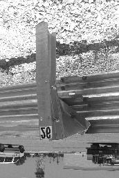
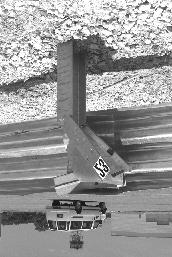
11 Figure 2. Modified Thrie Beam Guardrail installation before test a.
12 The test reported herein (test a) corresponds to NCHRP Report 350 test designation The CIP for this test was determined using information contained in NCHRP Report 350 and accordingly was determined to be the midpoint of the span between posts 17 and 18 of the modified thrie beam guardrail. EVALUATION CRITERIA The crash test performed was evaluated in accordance with the criteria presented in NCHRP Report 350. As stated in NCHRP Report 350, Safety performance of a highway appurtenance cannot be measured directly but can be judged on the basis of three factors: structural adequacy, occupant risk, and vehicle trajectory after collision. Accordingly, the following safety evaluation criteria from table 5.1 of NCHRP Report 350 were used to evaluate the crash test reported herein:! Structural Adequacy A. Test article should contain and redirect the vehicle; the vehicle should not penetrate, underride, or override the installation, although controlled lateral deflection of the test article is acceptable.! Occupant Risk D. Detached elements, fragments, or other debris from the test article should not penetrate or show potential for penetrating the occupant compartment, or present an undue hazard to other traffic, pedestrians, or personnel in a work zone. Deformation of, or intrusions into, the occupant compartment that could cause serious injuries should not be permitted. G. It is preferable, although not essential, that the vehicle remain upright during and after the collision.! Vehicle Trajectory K. After collision, it is preferable that the vehicle s trajectory not intrude into adjacent traffic lanes. M. The exit angle from the test article preferably should be less than 60 percent of the test impact angle, measured at time of vehicle loss of contact with the test device.
13 CRASH TEST AND DATA ANALYSIS PROCEDURES The crash test and data analysis procedures were in accordance with guidelines presented in NCHRP Report 350. Brief descriptions of these procedures are presented as follows. Electronic Instrumentation and Data Processing The test vehicle was instrumented with three solid-state angular rate transducers to measure roll, pitch, and yaw rates; a triaxial accelerometer near the vehicle center of gravity to measure longitudinal, lateral, and vertical acceleration levels; a back-up biaxial accelerometer in the rear of the vehicle to measure longitudinal and lateral acceleration levels; and another back-up biaxial accelerometer in the front of the cab of the vehicle to measure longitudinal and lateral acceleration levels. The accelerometers were strain-gauge type with a linear millivolt output proportional to acceleration. The electronic signals from the accelerometers and transducers were transmitted to a base station by means of constant bandwidth FM/FM telemetry link for recording on magnetic tape and for display on a real-time strip chart. Calibration signals were recorded before and after the test, and an accurate time reference signal was simultaneously recorded with the data. Pressure-sensitive switches on the bumper of the impacting vehicle were actuated just prior to impact by wooden dowels to indicate the elapsed time over a known distance to provide a measurement of impact velocity. The initial contact also produced an "event" mark on the data record to establish the exact instant of contact with the installation. The multiplex of data channels, transmitted on one radio frequency, was received at the data acquisition station and demultiplexed into separate tracks of Inter-Range Instrumentation Group (I.R.I.G.) tape recorders. After the test, the data were played back from the tape machines, filtered with an SAE J211 filter, and digitized using a microcomputer for analysis and evaluation of impact performance. The digitized data were then processed using two computer programs: DIGITIZE and PLOTANGLE. Brief descriptions of the functions of these two computer programs are provided as follows: The DIGITIZE program uses digitized data from vehicle-mounted linear accelerometers to compute occupant/compartment impact velocities, time of occupant/compartment impact after vehicle impact, and the highest 10-ms average ridedown acceleration. The DIGITIZE program also calculates a vehicle impact velocity and the change in vehicle velocity at the end of a given impulse period. In addition, maximum average accelerations over 50-ms intervals in each of the three directions are computed. For reporting purposes, the data from the vehicle-mounted accelerometers were then filtered with a 60-Hz digital filter and acceleration versus time curves for the longitudinal, lateral, and vertical directions were plotted using a commercially available software package (Excel 97).
14 The PLOTANGLE program used the digitized data from the yaw, pitch, and roll rate transducers to compute angular displacement in degrees at s intervals and then instructs a plotter to draw a reproducible plot: yaw, pitch, and roll versus time. These displacements are in reference to the vehicle-fixed coordinate system with the initial position and orientation of the vehiclefixed coordinate system being that which existed at initial impact. Anthropomorphic Dummy Instrumentation Use of a dummy in the 8000S vehicle is optional according to NCHRP Report 350 and there was no dummy used in the test with the 8000S vehicle. Photographic Instrumentation and Data Processing Photographic coverage of the test included three high-speed cameras: one overhead with a field of view perpendicular to the ground and directly over the impact point; one placed behind the installation at an angle; and a third placed to have a field of view parallel to and aligned with the installation at the downstream end. A flash bulb activated by pressure-sensitive tape switches was positioned on the impacting vehicle to indicate the instant of contact with the installation and was visible from each camera. The films from these high-speed cameras were analyzed on a computer-linked Motion Analyzer to observe phenomena occurring during the collision and to obtain time-event, displacement, and angular data. A Betacam, a VHS-format video camera and recorder, and still cameras were used to record and document the condition of the test vehicle and installation before and after the test. Test Vehicle Propulsion and Guidance The test vehicle was towed into the test installation using a steel cable guidance and reverse tow system. A steel cable for guiding the test vehicle was tensioned along the path, anchored at each end, and threaded through an attachment to the front wheel of the test vehicle. An additional steel cable was connected to the test vehicle, passed around a pulley near the impact point, through a pulley on the tow vehicle, and then anchored to the ground such that the tow vehicle moved away from the test site. A 2- to-1 speed ratio between the test and tow vehicle existed with this system. Just prior to impact with the installation, the test vehicle was released to be free-wheeling and unrestrained. The vehicle remained free-wheeling, i.e., no steering or braking inputs, until the vehicle cleared the immediate area of the test site, at which time brakes on the vehicle were activated to bring it to a safe and controlled stop.
15 III. CRASH TEST RESULTS TEST a (NCHRP Report 350 Test No. 4-12) A 1988 GMC 7000 single-unit truck, shown in figures 3 and 4, was used for the crash test. Test inertia weight of the vehicle was 8000 kg, and its gross static weight was 8000 kg. The height to the lower edge of the vehicle bumper was 520 mm and it was 815 mm to the upper edge of the bumper. Additional dimensions and information on the vehicle are given in figure 5. The vehicle was directed into the installation using the cable reverse tow and guidance system, and was released to be free-wheeling and unrestrained just prior to impact. The test was performed the morning of June 12, No rain had occurred for the 10 days prior to the test. Moisture content at posts 18, 20, and 22 was 6.7%, 4.0%, and 5.1%, respectively. Weather conditions during the time of the test were as follows: Wind Speed: 16 km/h; Wind Direction: 345 degrees with respect to the vehicle (vehicle was traveling in a southwesterly direction); Temperature: 34EC; Relative Humidity: 51 percent. Test Description The vehicle, traveling at 78.8 km/h, impacted the modified thrie beam guardrail 750 mm before post 18 at an impact angle of 15.7 degrees. Shortly after impact, post 18 and then post 17 moved. By s after impact, the vehicle contacted post 18 and at s, post 19 moved. The vehicle began to redirect at s and post 20 moved at s. At s, the vehicle contacted post 19 and at s, post 21 moved. Post 22 moved at s and the vehicle contacted post 21 at s. Post 23 moved at s, the right rear tire contacted the guardrail at s, and the front of the vehicle contacted post 22 at s. The vehicle was traveling parallel with the guardrail at s at a speed of 64.6 km/h. At s, the front wheels turned to the right and the front of the vehicle lost contact with the rail at s. The rear of the vehicle lost contact with the guardrail near post 26 at s and was traveling at 64.0 km/h and an exit angle of 8.2 degrees. The vehicle rotated clockwise at s and contacted the guardrail between posts 27 and 28 at s. At s, the front wheels turned to the left and at s, the vehicle lost contact with the guardrail just past post 30. The vehicle continued forward and then contacted the ET-2000 between posts 37 and 38 at s. As the vehicle continued forward, the vehicle pulled the ET-2000 head off the end. The vehicle rode off the end of the terminal and brakes on the vehicle were applied at 4.9 s. The vehicle subsequently came to rest 70.7 m down from impact and in line with the installation. Sequential photographs of the test period are shown in figures 6 and 7.
16 Figure 3. Vehicle/installation geometrics for test a.


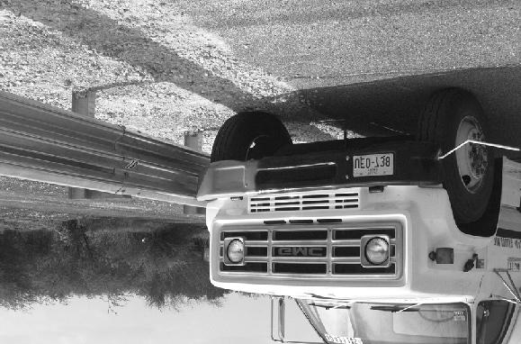
17 Figure 4. Vehicle before test a.
18 Figure 5. Vehicle properties for test a.


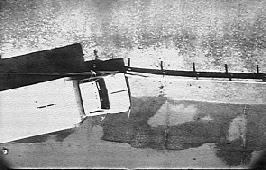
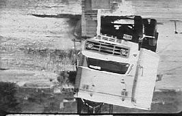
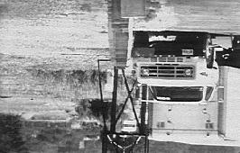
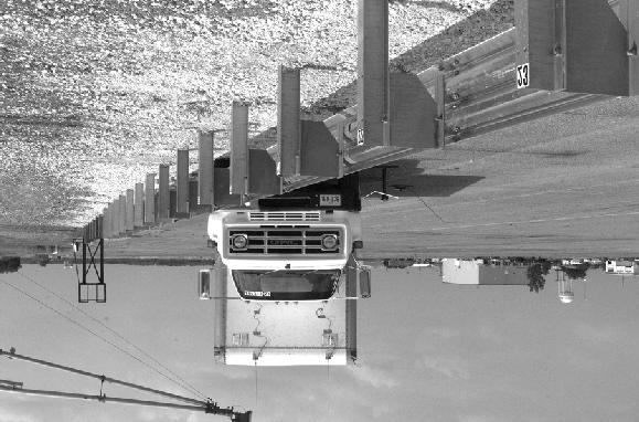
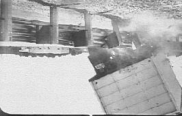
19 0.000 s s s s Figure 6. Sequential photographs for test a (overhead and frontal views).


20 0.692 s s s s Figure 6. Sequential photographs for test a (overhead and frontal views) (continued).


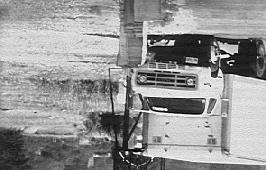
21 0.000 s s s s s s s s Figure 7. Sequential photographs for test a (rear view).
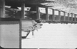
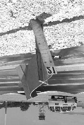
22 Damage to Test Installation Damage to the modified thrie beam guardrail is shown in figures 8 and 9. Posts 19 through 26 were deformed and the blockouts on those posts were significantly deformed. The blockouts on posts 17, 18, and 27 were slightly deformed. The guardrail bolts pulled through the thrie beam at posts 20, 23, 24, and 25. Tire marks were on the face of posts 20 and 21. Length of contact during the initial collision was 16.0 m of which the truck rode on top of the thrie beam for 2.8 m. The second contact occurred between posts 27 and 28 and continued to just past post 30. The third contact occurred between posts 37 and 38 and the vehicle rode off the end, taking the ET-2000 head off the end. Maximum dynamic deflection during the test was 0.71 m and maximum permanent deformation was 0.51 m, both occurring near post 21. Vehicle Damage Minimal damage was sustained by the vehicle as shown in figure 10. Structural damage was received by the front axle and right front wheel. The lower right front corner of the cargo box received a dent as well as the right side fuel tank. The bumper and supports, hood, right front quarter panel, grill, and right door step were damaged. The right door was jammed and the right outside tire received gouges. Maximum exterior vehicle crush was 140 mm at the right front corner of the bumper. The interior of the vehicle is shown in figure 11. Occupant Risk Values Occupant risk values are not required for this test, but were computed and are reported for information only. Data from the accelerometer located at the vehicle center of gravity were digitized and values are as follows: In the longitudinal direction, the occupant impact velocity was 3.5 m/s at s, the highest s occupant ridedown acceleration was -2.9 g s from to s, and the maximum s average acceleration was -1.4 g s between and s. In the lateral direction, the occupant impact velocity was -2.4 m/s at s, the highest s occupant ridedown acceleration was 3.8 g s from to s, and the maximum s average was 2.3 g s between and s. These data and other pertinent information from the test are summarized in figure 12. Vehicle angular displacements are displayed in figure 13. Vehicular accelerations versus time traces are presented in figures 14 through 20.


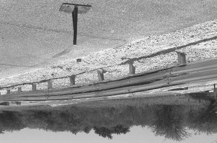
23 Figure 8. After-impact trajectory for test a.
24 Figure 9. Installation near initial impact after test a.


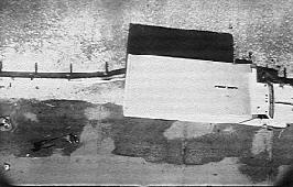
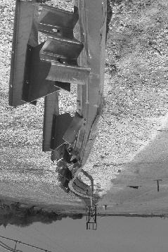
25 Second impact Third impact Figure 10. Installation near second and third impact after test a.


26 Figure 11. Vehicle after test a.


27 Before test After test Figure 12. Interior of vehicle for test a.
 Curb... Test Inertial... Dummy... Gross Static.")

 x-direction... y-direction... PHD (g s)... ASI... Max. 0.050-s Average (g's) x-direction... y-direction... z-direction... 78.8 15.7 64.0 8.")
... Post-Impact Behavior (during 1.0 s after impact) Max. Yaw Angle (deg)... Max. Pitch Angle (deg)... Max. Roll Angle (deg).")
28 0.000 s s s s General Information Test Agency... Test No.... Date... Test Article Type... Name... Installation Length (m)... Material or Key Elements... Soil Type and Condition... Test Vehicle Type... Designation... Model... Mass (kg) Curb... Test Inertial... Dummy... Gross Static... Texas Transportation Institute a 06/12/98 Guardrail Modified Thrie Beam Guardrail gauge thrie beam on W150x14 steel posts and steel blockouts Standard Soil, Dry Production 8000S 1988 GMC 7000 Single-Unit Truck No dummy 8000 Impact Conditions Speed (km/h)... Angle (deg)... Exit Conditions Speed (km/h)... Angle (deg)... Occupant Risk Values Impact Velocity (m/s) x-direction... y-direction... THIV (km/h)... Ridedown Accelerations (g's) x-direction... y-direction... PHD (g s)... ASI... Max s Average (g's) x-direction... y-direction... z-direction Test Article Deflections (m) Dynamic... Permanent... Vehicle Damage Exterior VDS... CDC... Maximum Exterior Vehicle Crush (mm)... Interior OCDI... Max. Occ. Compart. Deformation (mm)... Post-Impact Behavior (during 1.0 s after impact) Max. Yaw Angle (deg)... Max. Pitch Angle (deg)... Max. Roll Angle (deg) N/A N/A 140 RS Figure 13. Summary of results for test a, NCHRP Report 350 test 4-12.
29 Crash Test a Vehicle Mounted Rate Transducers Roll Displacement (deg) Axes are vehicle-fixed. Sequence for determining orientation is: 1. Yaw 2. Pitch 3. Roll Pitch Yaw Time after impact (s) Figure 14. Vehicle angular displacements for test a.
30 60 Hz Filter Crash Test a Accelerometer at center of gravity Test Article: Modified Thrie Beam Guardrail Test Vehicle: 1988 GMC 7000 Single-unit Truck Test Inertial Weight: 8000 kg Gross Static Weight: 8000 kg Impact Speed: 78.8 km/h Impact Angle: 15.7 degrees at CIP Longitudinal acceleration (g's) Time after impact (s) Figure 15. Vehicle longitudinal accelerometer trace for test a (accelerometer located at center of gravity).
31 60 Hz Filter Crash Test a Accelerometer at center of gravity Lateral acceleration (g's) Test Article: Modified Thrie Beam Guardrail Test Vehicle: 1988 GMC 7000 Single-unit Truck Test Inertial Weight: 8000 kg Gross Static Weight: 8000 kg Impact Speed: 78.8 km/h Impact Angle: 15.7 degrees at CIP Time after impact (s) Figure 16. Vehicle lateral accelerometer traces for test a (accelerometer located at center of gravity).
32 60 Hz Filter Crash Test a Accelerometer at center of gravity Test Article: Modified Thrie Beam Guardrail Test Vehicle: 1988 GMC 7000 Single-unit Truck Test Inertial Weight: 8000 kg Gross Static Weight: 8000 kg Impact Speed: 78.8 km/h Impact Angle: 15.7 degrees at CIP 4 Vertical acceleration (g's) Time after impact (s) Figure 17. Vehicle vertical accelerometer trace for test a (accelerometer located at center of gravity).
33 60 Hz Filter Crash Test a Accelerometer in front section of cab of truck Test Article: Modified Thrie Beam Guardrail Test Vehicle: 1988 GMC 7000 Single-unit Truck Test Inertial Weight: 8000 kg Gross Static Weight: 8000 kg Impact Speed: 78.8 km/h Impact Angle: 15.7 degrees at CIP Longitudinal acceleration (g's) Time after impact (s) Figure 18. Vehicle longitudinal accelerometer trace for test a (accelerometer located in front section of the cab of the vehicle).
34 60 Hz Filter Crash Test a Accelerometer in front section of cab of truck Test Article: Modified Thrie Beam Guardrail Test Vehicle: 1988 GMC 7000 Single-unit Truck Test Inertial Weight: 8000 kg Gross Static Weight: 8000 kg Impact Speed: 78.8 km/h Impact Angle: 15.7 degrees at CIP 4 Lateral acceleration (g's) Time after impact (s) Figure 19. Vehicle lateral accelerometer traces for test a (accelerometer located in front section of the cab of the vehicle).
35 60 Hz Filter Crash Test a Accelerometer over rear axle Test Article: Modified Thrie Beam Guardrail Test Vehicle: 1988 GMC 7000 Single-unit Truck Test Inertial Weight: 8000 kg Gross Static Weight: 8000 kg Impact Speed: 78.8 km/h Impact Angle: 15.7 degrees at CIP Longitudinal acceleration (g's) Time after impact (s) Figure 20. Vehicle longitudinal accelerometer trace for test a (accelerometer located over rear axles).
36 60 Hz Filter Crash Test a Accelerometer over rear axle Test Article: Modified Thrie Beam Guardrail Test Vehicle: 1988 GMC 7000 Single-unit Truck Test Inertial Weight: 8000 kg Gross Static Weight: 8000 kg Impact Speed: 78.8 km/h Impact Angle: 15.7 degrees at CIP 4 Lateral acceleration (g's) Time after impact (s) Figure 21. Vehicle lateral accelerometer traces for test a (accelerometer located over rear axles).
37 IV. SUMMARY OF FINDINGS AND CONCLUSIONS SUMMARY OF FINDINGS The modified thrie beam guardrail was contained and smoothly redirected. The vehicle did not penetrate, underride, or override the installation. No detached elements, fragments, or other debris were present to penetrate or to show potential for penetrating the occupant compartment, nor to present undue hazard to others in the area. No deformation or intrusion into the occupant compartment occurred. The vehicle remained upright and stable during and after the collision. The vehicle did not intrude into adjacent traffic lanes as it remained adjacent to the guardrail. Exit angle at loss of contact was 8.2 degrees, which was 52 percent of the impact angle. CONCLUSIONS As can be seen in table 4, the modified thrie beam guardrail met all requirements for NCHRP Report 350 test designation 4-12.
38 Table 1. Performance evaluation summary for test a, NCHRP Report 350 test Test Agency: Texas Transportation Institute Test No.: a Test Date: 06/12/98 NCHRP Report 350 Evaluation Criteria Test Results Assessment Structural Adequacy A. Test article should contain and redirect the vehicle; the vehicle should not penetrate, underride, or override the installation, although controlled lateral deflection of the test article is acceptable. Occupant Risk D. Detached elements, fragments, or other debris from the test article should not penetrate or show potential for penetrating the occupant compartment, or present an undue hazard to other traffic, pedestrians, or personnel in a work zone. Deformations of, or intrusions into, the occupant compartment that could cause serious injuries should not be permitted. G. It is preferable, although not essential, that the vehicle remain upright during and after collision. Vehicle Trajectory K. After collision, it is preferable that the vehicle's trajectory not intrude into adjacent traffic lanes. M. The exit angle from the test article preferably should be less than 60 percent of test impact angle, measured at time of vehicle loss of contact with test device. The modified thrie beam guardrail was contained and smoothly redirected. The vehicle did not penetrate, underride, or override the installation. No detached elements, fragments, or other debris were present to penetrate or to show potential for penetrating the occupant compartment, nor to present undue hazard to others in the area. No deformation or intrusion into the occupant compartment occurred. The vehicle remained upright and stable during and after the collision. The vehicle did not intrude into adjacent traffic lanes as it remained adjacent to the guardrail. Exit angle at loss of contact was 8.2 degrees, which was 52 percent of the impact angle. Pass Pass Pass Pass Pass
39 REFERENCES 1. H. E. Ross, Jr., D. L. Sicking, R. A. Zimmer, and J. D. Michie, Recommended Procedures for the Safety Performance Evaluation of Highway Features, NCHRP Report 350, Transportation Research Board, Washington, D.C., J. D. Michie, Recommended Procedures for the Safety Performance Evaluation of Highway Appurtenances, NCHRP Report 230, Transportation Research Board, Washington, D.C., King K. Mak, Roger P. Bligh, and Wanda L. Menges, Testing of State Roadside Safety Systems, Volume I: Technical Report, Report FHWA-RD , prepared by Texas Transportation Institute, The Texas A&M University, College Station, Texas, for Federal Highway Administration, Washington, D.C., February 1998.
TEXAS TRANSPORTATION INSTITUTE THE TEXAS A & M UNIVERSITY SYSTEM COLLEGE STATION, TEXAS 77843
 NCHRP REPORT 350 ASSESSMENT OF EXISTING ROADSIDE SAFETY HARDWARE by C. Eugene Buth, P.E. Senior Research Engineer Wanda L. Menges Associate Research Specialist and Sandra K. Schoeneman Research Associate
TEXAS TRANSPORTATION INSTITUTE THE TEXAS A & M UNIVERSITY SYSTEM COLLEGE STATION, TEXAS
 NCHRP REPORT 350 TEST 4-21 OF THE ALASKA MULTI-STATE BRIDGE RAIL THRIE-BEAM TRANSITION by C. Eugene Buth Senior Research Engineer William F. Williams Assistant Research Engineer Wanda L. Menges Associate
TEXAS TRANSPORTATION INSTITUTE THE TEXAS A & M UNIVERSITY SYSTEM COLLEGE STATION, TEXAS 77843
 NCHRP REPORT 350 TEST 3-11 OF THE STEEL-BACKED TIMBER GUARDRAIL by D. Lance Bullard, Jr., P.E. Associate Research Engineer Wanda L. Menges Associate Research Specialist and Sandra K. Schoeneman Research
GUARDRAIL TESTING MODIFIED ECCENTRIC LOADER TERMINAL (MELT) AT NCHRP 350 TL-2. Dean C. Alberson, Wanda L. Menges, and Rebecca R.
 AT NCHRP 350 TL-2. Dean C. Alberson, Wanda L. Menges, and Rebecca R.") GUARDRAIL TESTING MODIFIED ECCENTRIC LOADER TERMINAL (MELT) AT NCHRP 350 TL-2 Dean C. Alberson, Wanda L. Menges, and Rebecca R. Haug Prepared for The New England Transportation Consortium July 2002 NETCR
GUARDRAIL TESTING MODIFIED ECCENTRIC LOADER TERMINAL (MELT) AT NCHRP 350 TL-2 Dean C. Alberson, Wanda L. Menges, and Rebecca R. Haug Prepared for The New England Transportation Consortium July 2002 NETCR
TEXAS TRANSPORTATION INSTITUTE THE TEXAS A & M UNIVERSITY SYSTEM COLLEGE STATION, TEXAS 77843
 NCHRP REPORT 350 TEST 3-11 OF THE NEW YORK DOT PORTABLE CONCRETE BARRIER WITH I-BEAM CONNECTION (RETEST) by Roger P. Bligh, P.E. Assistant Research Engineer Wanda L. Menges Associate Research Specialist
NCHRP REPORT 350 TEST 4-12 OF THE MASSACHUSETTS S3-TL4 STEEL BRIDGE RAILING MOUNTED ON CURB AND SIDEWALK
 TEXAS TRANSPORTATION INSTITUTE NCHRP REPORT 350 TEST 4-12 OF THE MASSACHUSETTS S3-TL4 STEEL BRIDGE RAILING MOUNTED ON CURB AND SIDEWALK by C. Eugene Buth Research Engineer and Wanda L. Menges Associate
Form DOT F (8-72) Texas Transportation Institute The Texas A&M University System College Station, Texas
 Texas Transportation Institute The Texas A&M University System College Station, Texas") 1. Report No. FHWA/TX-02/4162-1 Technical Report Documentation Page 2. Government Accession No. 3. Recipient's Catalog No. 4. Title and Subtitle EVALUATION OF TEXAS GRID-SLOT PORTABLE CONCRETE BARRIER
1. Report No. FHWA/TX-02/4162-1 Technical Report Documentation Page 2. Government Accession No. 3. Recipient's Catalog No. 4. Title and Subtitle EVALUATION OF TEXAS GRID-SLOT PORTABLE CONCRETE BARRIER
Texas Transportation Institute The Texas A&M University System College Station, Texas
 1. Report No. FHWA/TX-05/9-8132-P7 4. Title and Subtitle TL-4 CRASH TESTING OF THE F411 BRIDGE RAIL 2. Government Accession No. 3. Recipient's Catalog No. 5. Report Date October 2004 Technical Report Documentation
NCHRP Report 350 Crash Testing and Evaluation of the S-Square Mailbox System
 TTI: 0-5210 NCHRP Report 350 Crash Testing and Evaluation of the S-Square Mailbox System ISO 17025 Laboratory Testing Certificate # 2821.01 Crash testing performed at: TTI Proving Ground 3100 SH 47, Building
MASH08 TEST 3-11 OF THE ROCKINGHAM PRECAST CONCRETE BARRIER
 Proving Ground Report No. 400001-RPC4 Report Date: July 2009 MASH08 TEST 3-11 OF THE ROCKINGHAM PRECAST CONCRETE BARRIER by C. Eugene Buth, P.E. Research Engineer William F. Williams, P.E. Assistant Research
CRASH TEST AND EVALUATION OF 3-FT MOUNTING HEIGHT SIGN SUPPORT SYSTEM
 TTI: 9-1002-15 CRASH TEST AND EVALUATION OF 3-FT MOUNTING HEIGHT SIGN SUPPORT SYSTEM ISO 17025 Laboratory Testing Certificate # 2821.01 Crash testing performed at: TTI Proving Ground 3100 SH 47, Building
A MASH Compliant W-Beam Median Guardrail System
 0 0 0 0 0 A MASH Compliant W-Beam Median Guardrail System By A. Y. Abu-Odeh, R. P. Bligh, W. Odell, A. Meza, and W. L. Menges Submitted: July 0, 0 Word Count:, + ( figures + tables=,000) =, words Authors:
MASH Test 3-11 on the T131RC Bridge Rail
 TTI: 9-1002-12 MASH Test 3-11 on the T131RC Bridge Rail ISO 17025 Laboratory Testing Certificate # 2821.01 Crash testing performed at: TTI Proving Ground 3100 SH 47, Building 7091 Bryan, TX 77807 Test
February 8, In Reply Refer To: HSSD/CC-104
 February 8, 2008 200 New Jersey Avenue, SE. Washington, DC 20590 In Reply Refer To: HSSD/CC-04 Barry D. Stephens, P.E. Sr. Vice President Engineering Energy Absorption Systems, Inc. 367 Cincinnati Avenue
Texas Transportation Institute The Texas A&M University System College Station, Texas
 1. Report No. FHWA/TX-07/0-5527-1 4. Title and Subtitle DEVELOPMENT OF A LOW-PROFILE TO F-SHAPE TRANSITION BARRIER SEGMENT 2. Government Accession No. 3. Recipient's Catalog No. Technical Report Documentation
MASH TEST 3-37 OF THE TxDOT 31-INCH W-BEAM DOWNSTREAM ANCHOR TERMINAL
 TTI: 9-1002 MASH TEST 3-37 OF THE TxDOT 31-INCH W-BEAM DOWNSTREAM ANCHOR TERMINAL ISO 17025 Laboratory Testing Certificate # 2821.01 Crash testing performed at: TTI Proving Ground 3100 SH 47, Building
Texas Transportation Institute The Texas A&M University System College Station, Texas
 2. Government Accession No. 3. Recipient's Catalog No. 1. Report No. FHWA/TX-03/0-4138-3 4. Title and Subtitle PERFORMANCE OF THE TXDOT T202 (MOD) BRIDGE RAIL REINFORCED WITH FIBER REINFORCED POLYMER BARS
STI Project: Barrier Systems, Inc. RTS-QMB Longitudinal Barrier. Page 38 of 40 QBOR1. Appendix F (Continued) Figure F-3
 Figure F-3") Barrier Systems, Inc. RTS-QMB Longitudinal Barrier STI Project: QBOR1 Page 38 of 40 Appendix F (Continued) Figure F-3 t=.500sec 115 meters overall 37.1 Impact Severity (kj).. 141.6 Angle (deg).. 25 Speed
Barrier Systems, Inc. RTS-QMB Longitudinal Barrier STI Project: QBOR1 Page 38 of 40 Appendix F (Continued) Figure F-3 t=.500sec 115 meters overall 37.1 Impact Severity (kj).. 141.6 Angle (deg).. 25 Speed
MASH TEST 3-11 OF THE TxDOT T222 BRIDGE RAIL
 TTI: 9-1002-12 MASH TEST 3-11 OF THE TxDOT T222 BRIDGE RAIL ISO 17025 Laboratory Testing Certificate # 2821.01 Crash testing performed at: TTI Proving Ground 3100 SH 47, Building 7091 Bryan, TX 77807 Test
Texas Transportation Institute The Texas A&M University System College Station, Texas
 1. Report No. FHWA/TX-04/9-8132-1 4. Title and Subtitle TESTING AND EVALUATION OF THE FLORIDA JERSEY SAFETY SHAPED BRIDGE RAIL 2. Government Accession No. 3. Recipient's Catalog No. 5. Report Date February
MASH TEST 3-10 ON 31-INCH W-BEAM GUARDRAIL WITH STANDARD OFFSET BLOCKS
 TTI: 9-1002 MASH TEST 3-10 ON 31-INCH W-BEAM GUARDRAIL WITH STANDARD OFFSET BLOCKS ISO 17025 Laboratory Testing Certificate # 2821.01 Crash testing performed at: TTI Proving Ground 3100 SH 47, Building
Evaluation and Design of ODOT s Type 5 Guardrail with Tubular Backup
 Evaluation and Design of ODOT s Type 5 Guardrail with Tubular Backup Draft Final Report Chuck A. Plaxico, Ph.D. James C. Kennedy, Jr., Ph.D. Charles R. Miele, P.E. for the Ohio Department of Transportation
VULCAN BARRIER TL-3 GENERAL SPECIFICATIONS
 VULCAN BARRIER TL-3 GENERAL SPECIFICATIONS I. GENERAL A. The VULCAN BARRIER TL-3 (VULCAN TL-3) shall be a highly portable and crashworthy longitudinal barrier especially suited for use as a temporary barrier
MASH TEST 3-11 OF THE TxDOT SINGLE SLOPE BRIDGE RAIL (TYPE SSTR) ON PAN-FORMED BRIDGE DECK
 ON PAN-FORMED BRIDGE DECK") TTI: 9-1002 MASH TEST 3-11 OF THE TxDOT SINGLE SLOPE BRIDGE RAIL (TYPE SSTR) ON PAN-FORMED BRIDGE DECK ISO 17025 Laboratory Testing Certificate # 2821.01 Crash testing performed at: TTI Proving Ground
TTI: 9-1002 MASH TEST 3-11 OF THE TxDOT SINGLE SLOPE BRIDGE RAIL (TYPE SSTR) ON PAN-FORMED BRIDGE DECK ISO 17025 Laboratory Testing Certificate # 2821.01 Crash testing performed at: TTI Proving Ground
VERIFICATION & VALIDATION REPORT of MGS Barrier Impact with 1100C Vehicle Using Toyota Yaris Coarse FE Model
 VERIFICATION & VALIDATION REPORT of MGS Barrier Impact with 1100C Vehicle Using Toyota Yaris Coarse FE Model CCSA VALIDATION/VERIFICATION REPORT Page 1 of 4 Project: CCSA Longitudinal Barriers on Curved,
July 10, Refer to: HSA-10/CC-78A
 July 10, 2003 Refer to: HSA-10/CC-78A Barry D. Stephens, P.E. Senior Vice President of Engineering ENERGY ABSORPTION Systems, Inc. 3617 Cincinnati Avenue Rocklin, California 95765 Dear Mr. Stephens: Your
TEXAS TRANSPORTATION INSTITUTE THE TEXAS A & M UNIVERSITY SYSTEM COLLEGE STATION, TEXAS
 TEXAS TRANSPORTATION INSTITUTE Test Level 2 Evaluation of the RENCO Ren-Gard 815 Truck Mounted Attenuator by C. Eugene Buth Senior Research Engineer and Wanda L. Menges Associate Research Specialist Contract
VULCAN BARRIER TL-3 GENERAL SPECIFICATIONS
 VULCAN BARRIER TL-3 GENERAL SPECIFICATIONS I. GENERAL A. The VULCAN BARRIER TL-3 (VULCAN TL-3) shall be a highly portable and crashworthy longitudinal barrier especially suited for use as a temporary barrier
CRASH TEST AND EVALUATION OF TEMPORARY WOOD SIGN SUPPORT SYSTEM FOR LARGE GUIDE SIGNS
 TTI: 9-1002-15 CRASH TEST AND EVALUATION OF TEMPORARY WOOD SIGN SUPPORT SYSTEM FOR LARGE GUIDE SIGNS ISO 17025 Laboratory Testing Certificate # 2821.01 Crash testing performed at: TTI Proving Ground 3100
Transportation Institute
 .JIIIIIII"" Texas Transportation Institute SUMMARY OF TESTING ON 'l'he RENCO TRUCK MOUNTED ATTENUATOR by Wanda L. Menges Associate Research Specialist C. Eugene Buth, P.E. Senior Research Engineer and
I I TEXAS TRANSPORTATION INSTITUTE THE TEXAS A & M UNIVERSITY SYSTEM COLLEGE STATION, TEXAS
 TEXAS TRANSPORTATON NSTTUTE Testing and Evaluation of the Vermont W-Beam Guardrail Terminal for Low Speed Areas by Althea G. Arnold Assistant Research Engineer Wanda L. Menges Associate Research Specialist
14. Sponsoring Agency Code McLean, Virginia
 TECHNICAL REPORT DOCUMENTATION PAGE I. Report No. 2. Government Accession No. FHWA-RD-93-069 4. Title and Subtitle TESTING OF NEW BRIDGE RAIL AND TRANSITION DESIGNS Volume XII: Appendix K Oregon Transition
Virginia Department of Transportation
 TEST REPORT FOR: Virginia Department of Transportation SKT SP 350 50 (15.24 m) System PREPARED FOR: Virginia Department of Transportation 1401 E. Broad St. Richmond, VA 23219 TEST REPORT NUMBER: REPORT
Evaluation of the Sequential Dynamic Curve Warning System Summary of Full Report Publication No. FHWA-15-CAI-012-A November 2015
 Evaluation of the Sequential Dynamic Curve Warning System Summary of Full Report Publication No. FHWA-15-CAI-012-A November 2015 Source: ISU/TTI Notice This document is disseminated under the sponsorship
MASH TEST 3-21 ON TL-3 THRIE BEAM TRANSITION WITHOUT CURB
 TTI: 9-1002-12 MASH TEST 3-21 ON TL-3 THRIE BEAM TRANSITION WITHOUT CURB ISO 17025 Laboratory Testing Certificate # 2821.01 Crash testing performed at: TTI Proving Ground 3100 SH 47, Building 7091 Bryan,
Manual for Assessing Safety Hardware
 American Association of State Highway and Transportation Officials Manual for Assessing Safety Hardware 2009 vii PREFACE Effective traffic barrier systems, end treatments, crash cushions, breakaway devices,
Technical Report Documentation Page Form DOT F (8-72) Reproduction of completed page authorized
 Reproduction of completed page authorized") 1. Report No. FHWA/TX-05/0-4162-3 4. Title and Subtitle 2. Government Accession No. 3. Recipient's Catalog No. DEVELOPMENT OF LOW-DEFLECTION PRECAST CONCRETE ARRIER 5. Report Date January 2005 Technical
1. Report No. FHWA/TX-05/0-4162-3 4. Title and Subtitle 2. Government Accession No. 3. Recipient's Catalog No. DEVELOPMENT OF LOW-DEFLECTION PRECAST CONCRETE ARRIER 5. Report Date January 2005 Technical
Universal TAU-IIR Redirective, Non-Gating, Crash Cushion
 TB 110927 Rev. 0 Page 1 of 5 Product Specification Universal TAU-IIR Redirective, Non-Gating, Crash Cushion I. General The Universal TAU-IIR system is a Redirective, Non-Gating Crash Cushion in accordance
Product Specification. ABSORB 350 TM TL-2 Non-Redirective, Gating, Crash Cushion Applied to Quickchange Moveable Barrier
 TB 000612 Rev. 0 Page 1 of 9 Product Specification ABSORB 350 TM TL-2 Non-Redirective, Gating, Crash Cushion Applied to Quickchange Moveable Barrier I. General The ABSORB 350 TM TL-2 System is a Non-Redirective,
Sponsored by Roadside Safety Research Program Pooled Fund Study No. TPF-5(114)
") Proving Ground Test Report No. 405160-23-2 Test Report Date: February 2012 MASH TEST 3-11 OF THE W-BEAM GUARDRAIL ON LOW-FILL BOX CULVERT by William F. Williams, P.E. Associate Research Engineer and Wanda
Proving Ground Test Report No. 405160-23-2 Test Report Date: February 2012 MASH TEST 3-11 OF THE W-BEAM GUARDRAIL ON LOW-FILL BOX CULVERT by William F. Williams, P.E. Associate Research Engineer and Wanda
Advances in Simulating Corrugated Beam Barriers under Vehicular Impact
 13 th International LS-DYNA Users Conference Session: Automotive Advances in Simulating Corrugated Beam Barriers under Vehicular Impact Akram Abu-Odeh Texas A&M Transportation Institute Abstract W-beam
Performance Level 1 Bridge Railings
 80 TRANSPORTATION RESEARCH RECORD 1500 Performance Level 1 Bridge Railings DEAN C. ALBERSON, WANDA L. MENGES, AND C. EUGENE BUTH Twenty-three states, FHW A, and the District of Columbia sponsored the project
PERFORMANCE EVALUATION OF THE PERMANENT NEW JERSEY SAFETY SHAPE BARRIER UPDATE TO NCHRP 350 TEST NO (2214NJ-2)
") PERFORMANCE EVALUATION OF THE PERMANENT NEW JERSEY SAFETY SHAPE BARRIER UPDATE TO NCHRP 350 TEST NO. 4-12 (2214NJ-2) Submitted by Karla A. Polivka, M.S.M.E., E.I.T. Research Associate Engineer Dean L.
PERFORMANCE EVALUATION OF THE PERMANENT NEW JERSEY SAFETY SHAPE BARRIER UPDATE TO NCHRP 350 TEST NO. 4-12 (2214NJ-2) Submitted by Karla A. Polivka, M.S.M.E., E.I.T. Research Associate Engineer Dean L.
FHW A-RD TESTING OF NEW BRIDGE RAIL AND TRANSITION DESIGNS Volume IX: Appendix H Illinois Side Mount Bridge Railing
 TECHNICAL REPORT DOCUMENTATION PAGE 1. Report No. 2. Goverrunent Accession No. FHW A-RD-93-066 4. Title and Subtitle TESTING OF NEW BRIDGE RAIL AND TRANSITION DESIGNS Volume IX: Appendix H Illinois Side
FAAC International, Inc.
 TEST REPORT FOR: FAAC International, Inc. J 355 HA M30 (K4) Bollard TESTED TO: ASTM F 2656-07 Standard Test Method for Vehicle Crash Testing of Perimeter Barriers Test M30 PREPARED FOR: FAAC International,
PERFORMANCE EVALUATION OF THE MODIFIED G4(1S) GUARDRAIL UPDATE TO NCHRP 350 TEST NO WITH 28" C.G. HEIGHT (2214WB-2)
 GUARDRAIL UPDATE TO NCHRP 350 TEST NO WITH 28 C.G. HEIGHT (2214WB-2)") PERFORMANCE EVALUATION OF THE MODIFIED G4(1S) GUARDRAIL UPDATE TO NCHRP 350 TEST NO. 3-11 WITH 28" C.G. HEIGHT (2214WB-2) Submitted by Karla A. Polivka, M.S.M.E., E.I.T. Research Associate Engineer Dean
PERFORMANCE EVALUATION OF THE MODIFIED G4(1S) GUARDRAIL UPDATE TO NCHRP 350 TEST NO. 3-11 WITH 28" C.G. HEIGHT (2214WB-2) Submitted by Karla A. Polivka, M.S.M.E., E.I.T. Research Associate Engineer Dean
Office of Safety & Traffic Operations R&D Federal Highway Administration August September Georgetown Pike
 TECHNICAL REPORT DOCUMENTATION PAGE I. Report No. 2. Government Accession No. FHWA-RD-93-067 4. Title and Subtitle TESTING OF NEW BRIDGE RAIL AND TRANSITION DESIGNS Volume X: Appendix I 42-in (1.07-m)
Appendix D. Figure D-1. ENCLOSURE 1 (4 Pages) SafeGuard TM Gate System
 SafeGuard TM Gate System") Appendix D Figure D-1 SafeGuard TM Gate System ENCLOSURE 1 (4 Pages) Appendix D (Continued) Figure D-4 SafeGuard TM Gate System Appendix D (Continued) Figure D-9 SafeGuardTM Gate System Page D-9 Figure
Appendix D Figure D-1 SafeGuard TM Gate System ENCLOSURE 1 (4 Pages) Appendix D (Continued) Figure D-4 SafeGuard TM Gate System Appendix D (Continued) Figure D-9 SafeGuardTM Gate System Page D-9 Figure
Evaluation of Barriers for Very High Speed Roadways
 TTI: 0-6071 Evaluation of Barriers for Very High Speed Roadways ISO 17025 Laboratory Testing Certificate # 2821.01 Crash testing performed at: TTI Proving Ground 3100 SH 47, Building 7091 Bryan, TX 77807
PERFORMANCE EVALUATION OF THE FREE-STANDING TEMPORARY BARRIER UPDATE TO NCHRP 350 TEST NO (2214TB-1)
") PERFORMANCE EVALUATION OF THE FREE-STANDING TEMPORARY BARRIER UPDATE TO NCHRP 350 TEST NO. 3-11 (2214TB-1) Submitted by Karla A. Polivka, M.S.M.E., E.I.T. Research Associate Engineer Dean L. Sicking, Ph.D.,
PERFORMANCE EVALUATION OF THE FREE-STANDING TEMPORARY BARRIER UPDATE TO NCHRP 350 TEST NO. 3-11 (2214TB-1) Submitted by Karla A. Polivka, M.S.M.E., E.I.T. Research Associate Engineer Dean L. Sicking, Ph.D.,
June 5, In Reply Refer To: HSSD/B-178. Mr. Kevin K. Groeneweg Mobile Barriers LLC Genesee Trail Road Golden, CO Dear Mr.
 June 5, 2008 1200 New Jersey Avenue, SE. Washington, DC 20590 In Reply Refer To: HSSD/B-178 Mr. Kevin K. Groeneweg Mobile Barriers LLC 24918 Genesee Trail Road Golden, CO 80401 Dear Mr. Groeneweg: This
BarrierGate. General Specifications. Manual Operations General Specifications
 BarrierGate General Specifications Manual Operations General Specifications BarrierGate GENERAL SPECIFICATIONS I. GENERAL A. The BarrierGate system (the gate) shall be designed and manufactured by Energy
Development of Combination Pedestrian-Traffic Bridge Railings
 TRANSPORTATION RESEARCH RECORD 1468 41 Development of Combination Pedestrian-Traffic Bridge Railings D. LANCE BULLARD, JR., WANDA L. MENGES, AND C. EUGENE BUTH Two bridge railing designs have been developed
TEST REPORT No. 2 ALUMINUM BRIDGE RAIL SYSTEMS. Prepared for. The Aluminum Association Inc. 818 Connecticut Avenue Washington, D.C.
 TEST REPORT No. 2 ALUMNUM BRDGE RAL SYSTEMS Prepared for The Aluminum Association nc. 818 Connecticut Avenue Washington, D.C. 26 by C. E. Buth Research Engineer G. G. Hayes Assoc. Research Physicist and
ASTM F TEST M30 ON THE RSS-3000 DROP BEAM SYSTEM
 Proving Ground Test Report No.: 510602-RSS3 Test Report Date: January 2014 ASTM F2656-07 TEST M30 ON THE RSS-3000 DROP BEAM SYSTEM by Dean C. Alberson, Ph.D., P.E. Research Engineer Michael S. Brackin,
RSA Protective Technologies
 TEST REPORT FOR: RSA Protective Technologies K12 Surface Mounted Bollard System TESTED TO: ASTM F 2656-07 Standard Test Method for Vehicle Crash Testing of Perimeter Barriers Test M50 PREPARED FOR: Battelle
DEVELOPMENT OF A MASH TL-3 MEDIAN BARRIER GATE
 TTI: 9-1002 DEVELOPMENT OF A MASH TL-3 MEDIAN BARRIER GATE ISO 17025 Laboratory Testing Certificate # 2821.01 Crash testing performed at: TTI Proving Ground 3100 SH 47, Building 7091 Bryan, TX 77807 Research/Test
Evaluation of the Midwest Guardrail System Stiffness Transition with Curb
 Duplication for publication or sale is strictly prohibited without prior written permission of the Transportation Research Board Paper No. -0 Evaluation of the Midwest Guardrail System Stiffness Transition
PR V2. Submitted by. Professor MIDWEST Vine Street (402) Submitted to
 Submitted to") FINAL REPORT PR4893118-V2 ZONE OF INTRUSION STUDY Submitted by John D. Reid, Ph.D. Professor Dean L.. Sicking, Ph.D., P.E. Professorr and MwRSF Director MIDWEST ROADSIDE SAFETY FACILITY University of Nebraska-Lincoln
FINAL REPORT PR4893118-V2 ZONE OF INTRUSION STUDY Submitted by John D. Reid, Ph.D. Professor Dean L.. Sicking, Ph.D., P.E. Professorr and MwRSF Director MIDWEST ROADSIDE SAFETY FACILITY University of Nebraska-Lincoln
SAFETY COMPLIANCE TESTING FOR FMVSS NO. 214S SIDE IMPACT PROTECTION (STATIC)
") REPORT NUMBER 214-GTL-09-002 SAFETY COMPLIANCE TESTING FOR S SIDE IMPACT PROTECTION (STATIC) MAZDA MOTOR CORPORATION 2009 MAZDA 3, PASSENGER CAR NHTSA NO. C95400 GENERAL TESTING LABORATORIES, INC. 1623
REPORT NUMBER 214-GTL-09-002 SAFETY COMPLIANCE TESTING FOR S SIDE IMPACT PROTECTION (STATIC) MAZDA MOTOR CORPORATION 2009 MAZDA 3, PASSENGER CAR NHTSA NO. C95400 GENERAL TESTING LABORATORIES, INC. 1623
PERFORMANCE EVALUATION OF THE FREE-STANDING TEMPORARY BARRIER UPDATE TO NCHRP 350 TEST NO WITH 28" C.G. HEIGHT (2214TB-2)
") PERFORMANCE EVALUATION OF THE FREE-STANDING TEMPORARY BARRIER UPDATE TO NCHRP 350 TEST NO. 3-11 WITH 28" C.G. HEIGHT (2214TB-2) Submitted by Karla A. Polivka, M.S.M.E., E.I.T. Research Associate Engineer
PERFORMANCE EVALUATION OF THE FREE-STANDING TEMPORARY BARRIER UPDATE TO NCHRP 350 TEST NO. 3-11 WITH 28" C.G. HEIGHT (2214TB-2) Submitted by Karla A. Polivka, M.S.M.E., E.I.T. Research Associate Engineer
Final Report Federal Highway Administration August September Georgetown Pike
 TECHNICAL REPORT DOCUMENTATION PAGE 1. Report No. 2. Government Accession No. FHW A-RD-93-065 4. Title and Subtitle TESTING OF NEW BRIDGE RAIL AND TRANSITION DESIGNS Volume VIII: Appendix G BR27C Bridge
W-Beam Guiderail Transition from Light to Heavy Posts
 TRANSPORTATION RESEARCH RECORD 1198 55 W-Beam Guiderail Transition from Light to Heavy Posts DONALD G. HERRING AND JAMES E. BRYDEN Two full-scale crash tests evaluated a transition between lightand heavy-post
CRASH TESTING AND EVALUATION OF WORK ZONE TRAFFIC CONTROL DEVICES
 Paper No. 980627 CRASH TESTING AND EVALUATION OF WORK ZONE TRAFFIC CONTROL DEVICES by King K. Mak Phone: 210-698-2068 Fax: 210-698-2068 e-mail: king@tti3a.tamu.edu Texas Transportation Institute The Texas
CRASH TESTING OF RSA/K&C ANTI-RAM FOUNDATION BOLLARD PAD IN ACCORDANCE WITH U.S. DEPARTMENT OF STATE DIPLOMATIC SECURITY SD-STD-02.
 CRASH TESTING OF RSA/K&C ANTI-RAM FOUNDATION BOLLARD PAD IN ACCORDANCE WITH U.S. DEPARTMENT OF STATE DIPLOMATIC SECURITY SD-STD-02.01 REVISION A Prepared for RSA Protective Technologies, LLC FINAL REPORT
Development and Validation of a Finite Element Model of an Energy-absorbing Guardrail End Terminal
 Development and Validation of a Finite Element Model of an Energy-absorbing Guardrail End Terminal Yunzhu Meng 1, Costin Untaroiu 1 1 Department of Biomedical Engineering and Virginia Tech, Blacksburg,
Midwest Guardrail System Without Blockouts
 Duplication for publication or sale is strictly prohibited without prior written permission of the Transportation Research Board Paper No. 13-0418 Midwest Guardrail System Without Blockouts by John D.
W-Beam Approach Treatment at Bridge Rail Ends Near Intersecting Roadways
 TRANSPORTATION RESEARCH RECORD 1133 51 W-Beam Approach Treatment at Bridge Rail Ends Near Intersecting Roadways M. E. BRONSTAD, M. H. RAY, J. B. MAYER, JR., AND c. F. MCDEVITT This paper is concerned with
AASHTO Manual for Assessing Safety Hardware, AASHTO/FHWA Joint Implementation Plan Standing Committee on Highways September 24, 2015
 AASHTO Manual for Assessing Safety Hardware, 2015 AASHTO/FHWA Joint Implementation Plan Standing Committee on Highways September 24, 2015 Full Scale MASH Crash Tests (NCHRP 22-14(02)) Conducted several
SUMMARY CHANGES FOR NCHRP REPORT 350 GUIDELINES [NCHRP (02)] Keith A. Cota, Chairman Technical Committee on Roadside Safety June 14, 2007
![SUMMARY CHANGES FOR NCHRP REPORT 350 GUIDELINES [NCHRP (02)] Keith A. Cota, Chairman Technical Committee on Roadside Safety June 14, 2007](/thumbs/87/97351925.jpg "SUMMARY CHANGES FOR NCHRP REPORT 350 GUIDELINES [NCHRP (02)] Keith A. Cota, Chairman Technical Committee on Roadside Safety June 14, 2007") SUMMARY CHANGES FOR NCHRP REPORT 350 GUIDELINES [NCHRP 22-14 (02)] Keith A. Cota, Chairman Technical Committee on Roadside Safety June 14, 2007 BACKGROUND Circular 482 (1962) First full scale crash test
SUMMARY CHANGES FOR NCHRP REPORT 350 GUIDELINES [NCHRP 22-14 (02)] Keith A. Cota, Chairman Technical Committee on Roadside Safety June 14, 2007 BACKGROUND Circular 482 (1962) First full scale crash test
CRASH TEST REPORT FOR PERIMETER BARRIERS AND GATES TESTED TO SD-STD-02.01, REVISION A, MARCH Anti-Ram Bollards
 CRASH TEST REPORT FOR PERIMETER BARRIERS AND GATES TESTED TO SD-STD-02.01, REVISION A, MARCH 2003 Anti-Ram Bollards Prepared for: RSA Protective Technologies, LLC 1573 Mimosa Court Upland, CA 91784 Test
Assessing Options for Improving Roadside Barrier Crashworthiness
 13 th International LS-DYNA Users Conference Session: Simulation Assessing Options for Improving Roadside Barrier Crashworthiness D. Marzougui, C.D. Kan, and K.S. Opiela Center for Collision Safety and
CRASH TEST REPORT FOR PERIMETER BARRIERS AND GATES TESTED TO SD-STD-02.01, REVISION A, MARCH Anti-Ram Bollards
 CRASH TEST REPORT FOR PERIMETER BARRIERS AND GATES TESTED TO SD-STD-02.01, REVISION A, MARCH 2003 Anti-Ram Bollards Prepared for: RSA Protective Technologies, LLC 1573 Mimosa Court Upland, CA 91784 Test
COMPARISON OF THE IMPACT PERFORMANCE OF THE G4(1W) AND G4(2W) GUARDRAIL SYSTEMS UNDER NCHRP REPORT 350 TEST 3-11 CONDITIONS
 AND G4(2W) GUARDRAIL SYSTEMS UNDER NCHRP REPORT 350 TEST 3-11 CONDITIONS") Paper No. 00-0525 COMPARISON OF THE IMPACT PERFORMANCE OF THE G4(1W) AND G4(2W) GUARDRAIL SYSTEMS UNDER NCHRP REPORT 350 TEST 3-11 CONDITIONS by Chuck A. Plaxico Associate Research Engineer Worcester Polytechnic
Paper No. 00-0525 COMPARISON OF THE IMPACT PERFORMANCE OF THE G4(1W) AND G4(2W) GUARDRAIL SYSTEMS UNDER NCHRP REPORT 350 TEST 3-11 CONDITIONS by Chuck A. Plaxico Associate Research Engineer Worcester Polytechnic
Wyoming Road Closure Gate
 38 TRANSPORTATION RESEARCH RECORD 1528 Wyoming Road Closure Gate KING K. MAK, ROGER P. BLIGH, AND WILLIAM B. WILSON Road closure gates are used to close certain highways when driving conditions become
MASH 2016 Implementation: What, When and Why
 MASH 2016 Implementation: What, When and Why Roger P. Bligh, Ph.D., P.E. Senior Research Engineer Texas A&M Transportation Institute June 7, 2016 2016 Traffic Safety Conference College Station, Texas Outline
Crash Testing Growth Common Roadside Hardware Systems Draft FHWA and AASHTO Requirements for Implementing MASH 2015
 64 th Annual Illinois Traffic Safety and Engineering Conference October 14, 2015 Crash Testing Growth Common Roadside Hardware Systems Draft FHWA and AASHTO Requirements for Implementing MASH 2015 1 https://www.youtube.com/watch?feature
REPORT NUMBER: 301-CAL SAFETY COMPLIANCE TESTING FOR FMVSS 301 FUEL SYSTEM INTEGRITY HONDA MOTOR COMPANY 2007 HONDA ACCORD 4-DOOR SEDAN
 REPORT NUMBER: 301-CAL-07-05 SAFETY COMPLIANCE TESTING FOR FMVSS 301 FUEL SYSTEM INTEGRITY HONDA MOTOR COMPANY 2007 HONDA ACCORD 4-DOOR SEDAN NHTSA NUMBER: C75304 CALSPAN TEST NUMBER: 8832-F301-05 CALSPAN
Slotted Rail Guardrail Terminal
 TRANSPORTATION RESEARCH RECORD 1500 43 Slotted Rail Guardrail Terminal KING K. MAK, ROGER P. BLIGH, HAYES E. Ross, JR., AND DEAN L. SICKING A slotted rail terminal (SRT) for W-beam guardrails was successfully
REPORT NUMBER: 301-MGA SAFETY COMPLIANCE TESTING FOR FMVSS 301R FUEL SYSTEM INTEGRITY REAR IMPACT
 REPORT NUMBER: 301-MGA-2011-008 SAFETY COMPLIANCE TESTING FOR FMVSS 301R FUEL SYSTEM INTEGRITY REAR IMPACT MAZDA MOTOR CORPORATION 2011 MAZDA 2 SPORT MT NHTSA NUMBER: CB5400 PREPARED BY: MGA RESEARCH CORPORATION
REPORT NUMBER: 301-MGA SAFETY COMPLIANCE TESTING FOR FMVSS 301R FUEL SYSTEM INTEGRITY REAR IMPACT
 REPORT NUMBER: 301-MGA-2010-007 SAFETY COMPLIANCE TESTING FOR FMVSS 301R FUEL SYSTEM INTEGRITY REAR IMPACT NISSAN MOTOR COMPANY LTD 2010 NISSAN CUBE NHTSA NUMBER: CA5205 PREPARED BY: MGA RESEARCH CORPORATION
REPORT NUMBER: 301-MGA SAFETY COMPLIANCE TESTING FOR FMVSS 301R FUEL SYSTEM INTEGRITY REAR IMPACT
 REPORT NUMBER: 301-MGA-2007-002 SAFETY COMPLIANCE TESTING FOR FMVSS 301R FUEL SYSTEM INTEGRITY REAR IMPACT NISSAN MOTOR CO., LTD. 2006 NISSAN PATHFINDER LE 4X2 NHTSA NUMBER: C65200 PREPARED BY: MGA RESEARCH
REPORT NUMBER: 301-CAL SAFETY COMPLIANCE TESTING FOR FMVSS 301 FUEL SYSTEM INTEGRITY REAR IMPACT FORD MOTOR COMPANY 2009 FORD F150 2-DOOR PICKUP
 REPORT NUMBER: 301-CAL-09-03 SAFETY COMPLIANCE TESTING FOR FMVSS 301 FUEL SYSTEM INTEGRITY REAR IMPACT FORD MOTOR COMPANY 2009 FORD F150 2-DOOR PICKUP NHTSA NUMBER: C90206 CALSPAN TRANSPORTATION SCIENCES
Evaluation of the Midwest Guardrail System stiffness transition with curb
 University of Nebraska - Lincoln DigitalCommons@University of Nebraska - Lincoln Civil Engineering Faculty Publications Civil Engineering 2016 Evaluation of the Midwest Guardrail System stiffness transition
REPORT NUMBER: 301-MGA SAFETY COMPLIANCE TESTING FOR FMVSS 301R FUEL SYSTEM INTEGRITY REAR IMPACT
 REPORT NUMBER: 301-MGA-2010-005 SAFETY COMPLIANCE TESTING FOR FMVSS 301R FUEL SYSTEM INTEGRITY REAR IMPACT NISSAN MOTOR COMPANY LTD 2010 NISSAN CUBE NHTSA NUMBER: CA5201 PREPARED BY: MGA RESEARCH CORPORATION
REPORT NUMBER: 301-CAL SAFETY COMPLIANCE TESTING FOR FMVSS 301 FUEL SYSTEM INTEGRITY REAR IMPACT MAZDA MOTOR CORPORATION 2008 MAZDA CX-9 SUV
 REPORT NUMBER: 301-CAL-08-03 SAFETY COMPLIANCE TESTING FOR FMVSS 301 FUEL SYSTEM INTEGRITY REAR IMPACT MAZDA MOTOR CORPORATION 2008 MAZDA CX-9 SUV NHTSA NUMBER: C85401 CALSPAN TRANSPORTATION SCIENCES CENTER
REPORT NUMBER: 301-CAL SAFETY COMPLIANCE TESTING FOR FMVSS 301 FUEL SYSTEM INTEGRITY REAR IMPACT
 REPORT NUMBER: 301-CAL-09-01 SAFETY COMPLIANCE TESTING FOR FMVSS 301 FUEL SYSTEM INTEGRITY REAR IMPACT HYUNDAI MOTOR COMPANY 2009 HYUNDAI ACCENT 4-DOOR SEDAN NHTSA NUMBER: C90503 CALSPAN TRANSPORTATION
OPTIMIZATION OF THRIE BEAM TERMINAL END SHOE CONNECTION
 TTI: 9-1002-15 OPTIMIZATION OF THRIE BEAM TERMINAL END SHOE CONNECTION ISO 17025 Laboratory Testing Certificate # 2821.01 Pendulum testing performed at: TTI Proving Ground 3100 SH 47, Building 7091 Bryan,
ANALYSIS OF DATA FROM THE THERMAL IMAGING INSPECTION SYSTEM PROJECT
 UMTRI-2009-38 DECEMBER 2009 ANALYSIS OF DATA FROM THE THERMAL IMAGING INSPECTION SYSTEM PROJECT PAUL E. GREEN UMTRI-2009-38 Analysis of Data from the Thermal Imaging Inspection System Project Paul E.
Remote, Redesigned Air Bag Special Study FOR NHTSA S INTERNAL USE ONLY Dynamic Science, Inc., Case Number ( J) 1998 Ford Taurus station
 1998 Ford Taurus station") Remote, Redesigned Air Bag Special Study FOR NHTSA S INTERNAL USE ONLY Dynamic Science, Inc., Case Number (1999-79-122J) 1998 Ford Taurus station wagon California September/1999 Technical Report Documentation
Remote, Redesigned Air Bag Special Study FOR NHTSA S INTERNAL USE ONLY Dynamic Science, Inc., Case Number (1999-79-122J) 1998 Ford Taurus station wagon California September/1999 Technical Report Documentation
Remote Combination Adaptive Driving Equipment Investigation Dynamic Science, Inc. (DSI), Case Number G 1990 Ford Bronco Arizona October
, Case Number G 1990 Ford Bronco Arizona October") Remote Combination Adaptive Driving Equipment Investigation Dynamic Science, Inc. (DSI), Case Number 2007-76-131G 1990 Ford Bronco Arizona October 2007 This document is disseminated under the sponsorship
Remote Combination Adaptive Driving Equipment Investigation Dynamic Science, Inc. (DSI), Case Number 2007-76-131G 1990 Ford Bronco Arizona October 2007 This document is disseminated under the sponsorship
Remote, Redesigned Air Bag Special Study FOR NHTSA S INTERNAL USE ONLY Dynamic Science, Inc., Case Number ( J) 1998 Dodge Caravan Indiana
 1998 Dodge Caravan Indiana") Remote, Redesigned Air Bag Special Study FOR NHTSA S INTERNAL USE ONLY Dynamic Science, Inc., Case Number (1998-073-111J) 1998 Dodge Caravan Indiana September/1998 Technical Report Documentation Page 1.
Remote, Redesigned Air Bag Special Study FOR NHTSA S INTERNAL USE ONLY Dynamic Science, Inc., Case Number (1998-073-111J) 1998 Dodge Caravan Indiana September/1998 Technical Report Documentation Page 1.
SAFETY COMPLIANCE TESTING FOR FMVSS NO. 401 INTERIOR TRUNK RELEASE
 REPORT NUMBER 401-STF-09-002 SAFETY COMPLIANCE TESTING FOR FMVSS NO. 401 INTERIOR TRUNK RELEASE HYUNDAI MOTOR COMPANY 2009 HYUNDAI GENESIS FOUR-DOOR PASSENGER CAR NHTSA NO. C90501 U.S. DOT SAN ANGELO TEST
TEXAS TRANSPORTATION INSTITUTE THE TEXAS A & M UNIVERSITY SYSTEM COLLEGE STATION. TEXAS
 TEX ASTRA NSPOR TA TION INS TITU TE NCHRP REPORT 350 TESTS 3-36 AND 3-30 OF THE WIDE REACT by Wanda L. Menges Associate Research Specialist and C. Eugene Buth Research Engineer Contract No. 400001-WDR9-11
SAFETY COMPLIANCE TESTING FOR FMVSS 225 Child Restraint Anchorage Systems
 FINAL REPORT NUMBER 225-MGA-06-002 SAFETY COMPLIANCE TESTING FOR FMVSS 225 GENERAL MOTORS CORPORATION 2006 HUMMER H3 NHTSA No. C60102 MGA RESEARCH CORPORATION 446 Executive Drive Troy, Michigan 48083 Test
REPORT NO. TR-P NC SAFETY COMPLIANCE TESTING FOR FMVSS 223 REAR IMPACT GUARDS 2007 TRANSFREIGHT TECHNOLOGY NHTSA NO.
 REPORT NO. SAFETY COMPLIANCE TESTING FOR FMVSS 223 REAR IMPACT GUARDS 2007 TRANSFREIGHT TECHNOLOGY NHTSA NO. RIG 009 PREPARED BY: KARCO ENGINEERING, LLC. 9270 HOLLY ROAD ADELANTO, CALIFORNIA 92301 SEPTEMBER
DEFLECTION LIMITS FOR TEMPORARY CONCRETE BARRIERS
 Midwest State s Regional Pooled Fund Research Program Fiscal Year 1998-1999 (Year 9) NDOR Research Project Number SPR-3(017) DEFLECTION LIMITS FOR TEMPORARY CONCRETE BARRIERS Submitted by Dean L. Sicking,
Low-Speed Crash Test Protocol (Version V) May 2002
 May 2002") Low-Speed Crash Test Protocol (Version V) May 2002 Insurance Institute for Highway Safety Low-Speed Crash Test Protocol (Version V) Low-Speed Test Configurations Four different low-speed crash tests, at
Low-Speed Crash Test Protocol (Version V) May 2002 Insurance Institute for Highway Safety Low-Speed Crash Test Protocol (Version V) Low-Speed Test Configurations Four different low-speed crash tests, at
REPORT NUMBER: 305-MGA
 REPORT NUMBER: 305-MGA-2011-004 SAFETY COMPLIANCE TESTING FOR FMVSS 305 Electric Powered Vehicles: Electrolyte Spillage and Electrical Shock Protection NISSAN MOTOR CO., LTD. 2011 NISSAN LEAF 5-DR HATCHBACK
Remote, Redesigned Air Bag Special Study Dynamic Science, Inc., Case Number ( C) 1998 Nissan Altima Texas August/1998
 1998 Nissan Altima Texas August/1998") Remote, Redesigned Air Bag Special Study Dynamic Science, Inc., Case Number ( 1998-49-136C) 1998 Nissan Altima Texas August/1998 Technical Report Documentation Page 1. Report No. 2. Government Accession
Remote, Redesigned Air Bag Special Study Dynamic Science, Inc., Case Number ( 1998-49-136C) 1998 Nissan Altima Texas August/1998 Technical Report Documentation Page 1. Report No. 2. Government Accession