K.L.N. COLLEGE OF ENGINEERING
|
|
|
- Kory Booker
- 6 years ago
- Views:
Transcription
1 K.L.N. COLLEGE OF ENGINEERING DEPARTMENT OF ELECTRICAL & ELECTRONICS ENGINEERING (Approved by AICTE, New Delhi, permanently affiliated to Anna University, Chennai) (Accredited by NBA upto , New Delhi) B.E. EEE V Semester - Students Hand book ODD Semester of This book contains the following: 1. Vision and Mission of the College and Department, Program Educational Objectives, Program Specific Outcomes, Program Outcomes. 2. Outcome Based Education, Benefits and Significance of accreditation. 3. Engineering Ethics. 4. Blooms Taxonomy. 5. Academic Calendar (Odd semester). 6. Class Time Table. 7. B.E. EEE Syllabus V Semester. 8. Lecture Schedule, Tutorial, Assignment questions. 9. Anna University question papers (Previous years). 10. Anna University - Malpractices and Punishment in University Examinations 11. OD Norms 12. About the College and Department 13. Faculty List, Mobile number, Mail ID 14. Placement Mock test paper. 15. General tips for effective communication and Leadership skills.
2 K.L.N. COLLEGE OF ENGINEERING DEPARTMENT OF ELECTRICAL AND ELECTRONICS ENGINEERING VISION AND MISSION OF THE COLLEGE VISION: To become a Premier Institute of National Repute by Providing Quality Education, Successful Graduation, Potential Employability and Advanced Research & Development through Academic Excellence. MISSION: To Develop and Make Students Competent Professional in the Dynamic Environment in the field of Engineering, Technology and Management by emphasizing Research, Social Concern and Ethical Values through Quality Education System. VISION AND MISSION OF THE DEPARTMENT VISION: To become a high standard of excellence in Education, Training and Research in the field of Electrical & Electronics Engineering and allied applications. MISSION: To produce excellent, innovative and Nationalistic Engineers with Ethical Values and to advance in the field of Electrical & Electronics Engineering and allied areas. Year of start & History of Intake HISTORY OF THE DEPARTMENT B.E. - EEE M.E. - PSE Ph.D. 1994, with an intake of , with an intake of , with an intake of , with an intake of 120 Year of start & History of Intake 2004, with an intake of , with an intake of 24 Year of Recognition as Research Centre 2012 First Renewal 2015, upto December 2018 Both UG & PG programs are permanently affiliated to Anna University, Chennai. Accreditation status First Accreditation Second Accreditation Third Accreditation Fourth Accreditation 3 YEARS W.E.F YEARS W.E.F YEARS W.E.F Academic Year , and , i.e., upto FACULTY PROFILE as on July 2017 Ph.D s Doing Ph.D M.E
3 PROGRAM EDUCATIONAL OBJECTIVES (PEOs) The Educational Objectives of the Electrical and Electronics Engineering (EEE) Programme represent major accomplishments that we expect our graduates to achieve after three to five years of graduation. More specifically our graduates are expected: PEO1: to excel in industrial or graduate work in Electrical and Electronics Engineering and allied fields PEO2: to practice their Professions conforming to Ethical Values and Environmentally friendly policies PEO3: to work in international and multi-disciplinary Environments PEO4: to successfully adapt to evolving Technologies and stay current with their Professions PROGRAM SPECIFIC OUTCOMES (PSOs) Electrical and Electronics Engineering Graduates will be able to: PSO1: Apply the fundamentals of mathematics, science and engineering knowledge to identify, formulate, design and investigate complex engineering problems of electric circuits, analog and digital electronic circuits, electrical machines and power systems. PSO2: Apply appropriate techniques and modern Engineering hardware and software tools in power systems to engage in life- long learning and to successfully adapt in multi-disciplinary environments. PSO3: Understand the impact of Professional Engineering solutions in societal and environmental context, commit to professional ethics and communicate effectively.
4 PROGRAM OUTCOMES (POs) Electrical and Electronics Engineering Graduates will be able to: PO1:Engineering knowledge: Apply the knowledge of mathematics, science, engineering fundamentals, and an engineering specialization to the solution of complex engineering problems. PO2:Problem analysis: Identify, formulate, review research literature, and analyze complex engineering problems reaching substantiated conclusions using first principles of mathematics, natural sciences, and engineering sciences. PO3:Design/development of solutions: Design solutions for complex engineering problems and design system components or processes that meet the specified needs with appropriate consideration for the public health and safety, and the cultural, societal, and environmental considerations. PO4:Conduct investigations of complex problems: Use research-based knowledge and research methods including design of experiments, analysis and interpretation of data, and synthesis of the information to provide valid conclusions. PO5:Modern tool usage: Create, select, and apply appropriate techniques, resources, and modern engineering and IT tools including prediction and modeling to complex engineering activities with an understanding of the limitations. PO6:The engineer and society: Apply reasoning informed by the contextual knowledge to assess societal, health, safety, legal and cultural issues and the consequent responsibilities relevant to the professional engineering practice. PO7:Environment and sustainability: Understand the impact of the professional engineering solutions in societal and environmental contexts, and demonstrate the knowledge of, and need for sustainable development. PO8:Ethics: Apply ethical principles and commit to professional ethics and responsibilities and norms of the engineering practice. PO9: Individual and team work: Function effectively as an individual, and as a member or leader in diverse teams, and in multidisciplinary settings. PO10: Communication: Communicate effectively on complex engineering activities with the engineering community and with society at large, such as, being able to comprehend and write effective reports and design documentation, make effective presentations, and give and receive clear instructions. PO11: Project management and finance: Demonstrate knowledge and understanding of the engineering and management principles and apply these to one s own work, as a member and leader in a team, to manage projects and in multidisciplinary environments. PO12: Life-long learning: Recognize the need for, and have the preparation and ability to engage in independent and life-long learning in the broadest context of technological change. OUTCOME BASED EDUCATION (OBE) In a traditional education system, students are given grades and rankings compared to each other. Content and performance expectations are based primarily on what was taught in the past to students of a given age. The goal of traditional education was to present the knowledge and skills of an older generation to the new generation of students, and to provide students with an environment in which to learn. The process paid little attention (beyond the classroom teacher) to whether or not students learn any of the material. An outcome is a culminating demonstration of learning; it is what the student should be able to do, at the end of a course/program, in-terms of the knowledge, skill and behavior. Outcome-based education is an approach to education in which decisions about the curriculum are driven by the exit learning outcomes that the students should display at the end of the course. In outcomebased education, product defines process. Outcome-based education can be summed up as results-oriented thinking and is the opposite of input-based education where the emphasis is on the educational process. Outcome-based education promotes fitness for practice and education for capability. BENEFITS AND SIGNIFICANCE OF ACCREDITATION The process of accreditation helps in realizing a number of benefits, such as: Helps the Institution to know its strengths, weaknesses and opportunities Initiates Institutions into innovative and modern methods of pedagogy Gives Institutions a new sense of direction and identity Provides society with reliable information on quality of education offered Promotes intra and inter-institutional interactions Accreditation signifies different things to different stakeholders. These are:
5 Benefits to Institutions Accreditation is market-driven and has an international focus. It assesses the characteristics of an Institution and its programmes against a set of criteria established by National Board of Accreditation. NBA s key objective is to contribute to the significant improvement of the Institutions involved in the accreditation process. Accreditation process quantifies the strengths, weaknesses in the processes adopted by the Institution and provides directions and opportunities for future growth. NBA provides a quality seal or label that differentiates the Institutions from its peers at the national level. This leads to a widespread recognition and greater appreciation of the brand name of Institutions and motivates the Institutions to strive for more. Benefits to Students Students studying in NBA accredited Institutions can be assured that they will receive education which is a balance between high academic quality and professional relevance and that the needs of the corporate world are well integrated into programmes, activities and processes. It signifies that he has entered the portals of an Institution, which has the essential and desirable features of quality professional education. Benefits to Employers Accreditation assures prospective employers that students come from a programme where the content and quality have been evaluated, satisfying established standards. It also signifies that the students passing out have acquired competence based on well-established technical inputs. Benefits to the Public Accredited status represents the commitment of the programme and the Institution to quality and continuous improvement. Catalyst for International Accreditations Due to accreditation from NBA, the Institution s systems and procedures get aligned with the Institution s Mission and Vision. All essential prerequisites for international accreditation are included in the accreditation process of NBA. Therefore, NBA acts as a catalyst for the Institutions planning to acquire International Accreditation. Benefits to Industry and Infrastructure Providers It signifies identification of quality of Institutional capabilities, skills and knowledge. Benefits to Parents It signifies that their ward goes through a teaching-learning environment as per accepted good practices. Benefits to Alumni It reassures alumni that alumni are products of an institute with a higher standing in terms of learning. Benefits to CountryAccreditation helps in gaining confidence of stakeholders and in giving a strong message that as a country, our technical manpower is of international standards and can be very useful in enhancing the global mobility for our technical manpower. ENGINEERING ETHICS Engineering Ethics is the set of rules and guidelines that engineers adhere to as a moral obligation to their profession and to the world. Engineering is a professional career that impact lives. When ethics is not followed, disaster often occurs; these disasters not only include huge monetary costs and environmental impacts, but also often result in the loss of human life. Engineering Ethics applies to every engineer and is very important. The National Society of Professional Engineers (NSPE) decides the overall standards and codes of ethics for all the engineering professions. The Preamble of the NSPE Code of Conduct for Engineers (2007) states: Engineers shall at all times recognize that their primary obligation is to protect the safety, health, property, and welfare of the public. If their professional judgment is overruled under circumstances where the safety, health, property, or welfare of the public are endangered, they shall notify their employer or client and such other authority as may be appropriate. Electrical Engineering Ethics Electrical Engineering is a type of engineering profession that deals with the creation of better electronics. Since our society is heading towards an era of technology, where all members of society will be affected, it is especially important for electrical engineers to follow a code of engineering ethics. For electrical engineers, an important set of guidelines is the Electrical Engineering Code of Ethics, published by IEEE.
6 IEEE code of ethics We, the members of the IEEE, in recognition of the importance of our technologies in affecting the quality of life throughout the world, and in accepting a personal obligation to our profession, its members and the communities we serve, do hereby commit ourselves to the highest ethical and professional conduct and agree: 1. to accept responsibility in making decisions consistent with the safety, health, and welfare of the public, and to disclose promptly factors that might endanger the public or the environment; 2. to avoid real or perceived conflicts of interest whenever possible, and to disclose them to affected parties when they do exist; 3. to be honest and realistic in stating claims or estimates based on available data; 4. to reject bribery in all its forms; 5. to improve the understanding of technology; its appropriate application, and potential consequences; 6. to maintain and improve our technical competence and to undertake technological tasks for others only if qualified by training or experience, or after full disclosure of pertinent limitations; 7. to seek, accept, and offer honest criticism of technical work, to acknowledge and correct errors, and to credit properly the contributions of others; 8. to treat fairly all persons and to not engage in acts of discrimination based on race, religion, gender, disability, age, national origin, sexual orientation, gender identity, or gender expression; 9. to avoid injuring others, their property, reputation, or employment by false or malicious action; 10. to assist colleagues and co-workers in their professional development and to support them in following this code of ethics. Engineering Ethics in College/Education The main engineering ethics problem that college students are face with is academic integrity. Academic integrity can show itself in the form of cheating by copying someone s work, intentional cheating, plagiarism, and/or self-plagiarism. However, professional ethics is something that can be learned even when it conflicts with personal ethics, as for example, a situation where you are personally okay with building a product that can harm the environment, yet save lives. You can learn professional ethics and realize that something that is harmful to the environment is not okay. Ethics codes can even help you see the bigger picture. For example, in the previous scenario, these codes can help you re-evaluate your ethics and realize that something that is harmful to the environment will eventually be harmful to the people around you and yourself. Engineering Ethics in the Professional World In the professional world, ethical engineering problems come up in many cases. One of these includes the case of a professional using someone else s work that is published in the widespread market of publication. Another is the case of a professional using someone else s work that is not published yet and stealing their idea. Engineers who have good engineering ethics often have a good sense of the value of life. They don t hesitate to admit that they made a mistake because they know that the cost of not owning up to your mistakes can have disastrous consequences. It might even cost a human life. Engineering Ethics in Companies Not only do individual engineers have to be conscious of engineering ethics, but also companies. Companies have to be aware of their Corporate Social Responsibility and Environmental Responsibility. Corporate Social Responsibility is a company s responsibility to give back to the community that they profit from and to behave ethically so that both they and their community can benefit. Environmental Responsibility is a business s initiative to leave the environment (where it is taking its resources from) the same, if not better, that it is found it.
7 BLOOM S TAXONOMY Definitions of the different levels of thinking skills in Bloom s taxonomy 1. Remember recalling relevant terminology, specific facts, or different procedures related to information and/or course topics. At this level, a student can remember something, but may not really understand it. 2. Understand the ability to grasp the meaning of information (facts, definitions, concepts, etc.) that has been presented. 3. Apply being able to use previously learned information in different situations or in problem solving. 4. Analyze the ability to break information down into its component parts. Analysis also refers to the process of examining information in order to make conclusions regarding cause and effect, interpreting motives, making inferences, or finding evidence to support statements/arguments. 5. Evaluate being able to judge the value of information and/or sources of information based on personal values or opinions. 6. Create the ability to creatively or uniquely apply prior knowledge and/or skills to produce new and original thoughts, ideas, processes, etc. At this level, students are involved in creating their own thoughts an idea. List of Action Words Related to Critical Thinking Skills
8 K.L.N.COLLEGE OF ENGINEERING, POTTAPALAYAM ACADEMIC CALENDAR - ODD Semester of UG & PG COURSES III, V, VII SEMESTER SUMMARY S.No Date Programme / Events Day June (Mon) Student development and training programmes : (12 th June- 24 th June 2017) - Departments (Mon) Faculty Meeting - I (Wed) Reopening Day - III,V&VII Semester UG classes 01 Class Committee Meeting - I (Thu) Student Counsellor Meeting I (Mon) Ramzan Holiday (Thu) Grievance redressal Committee Meeting (Fri) IIPC & IDCA review meeting-i 08 July (Mon) Commencement of Classes III & V Semester M.E, MBA & MCA Courses (Sat) 19 th Graduation Day (Wed) Class Test-I- (12 th 19 th July 2017) (Mon) Anti-Ragging Committee Meeting (Thu) Faculty Meeting - II (Mon) CIT I 31 s t July 07 th August August (Tue) Commencement of Classes-First year B.E./B.Tech (Tue) Remedial / Retest Classes (Mon) Krishna Jeyanthi Holiday (Tue) Independence Day Holiday (Fri) Student Counsellor Meeting II (Mon) Class Test-II- 21 st 28 th Aug Class Committee Meeting - II (Fri) Vinayagar Chathurthi Holiday (Sat) Parents Teachers Meeting 49 September (Sat) Bakrid Holiday (Mon) Faculty Meeting - III (Mon) CIT II 11 th 18 th Sep (Mon) Model Practical Examinations 25 th 28 th Sep (Thu) NBA CO attainment Even Semester of Finalization (Fri) Ayutha Pooja- Holiday (Sat) Vijaya Thasami Holiday October (Sun) Moharam - Holiday (Mon) Gandhi Jeyanthi - Holiday (Tue) Class Test- III - 3 r d -5 th Oct Students feedback on faculty, college facility, Course Outcome Survey (Thu) Class Committee Meeting - III (Fri) Faculty meeting - IV (Mon) Anna University Practical Examinations Tentative Slot I-Tentative (Sat) Model Theory Examinations (14 th 25 th Oct 2017) (Wed) Deepavali Holiday (Thu) Program Assessment Committee meeting-po-assessment Batch- 88 Planning for DAC meeting (Sat) Last Working Day-III,V,VII Semester B.E./B.Tech (Mon) Commencement of end semester Examinations (III,V & VII semester B.E./B.Tech) (Mon) Winter vacation Reopening day for the staff after Winter Vacation: (Monday) Reopening day for the Even semester of : (Monday). Academic Performance evaluation of faculty (Odd Semester) 11 th 15 th Dec 2017.

9
10 TIME DAY K.L.N. COLLEGE OF ENGINEERING, POTTAPALAYAM Department of Electrical and Electronics Engineering CLASS WISE TIME TABLE (ODD) Year/Sem/Sec : III / V / A Faculty In-charge : Dr.K.Gnanambal N C H PERIOD I II III IV V VI VII VIII PPE PSA/MPMC CS CSSS LAB L CSSS LAB BASED MON KRJ KG/EJ AM KK,EJ - KK,EJ U PSA CS EM-II EM-II(T) PE C&I LAB / EM LAB-II TUE KG AM SMK SMK,MML CVR AM,APSR /EJ, PLT WED THU FRI CS AM PE CVR MPMC EJ PSA KG CS AM PPE KRJ MPMC EJ EM-II SMK TPO PE CVR EM-II SMK CS(T) AM,APSR PPE KRJ MPMC EJ PSA KG PPE KRJ EM-II SMK C&I LAB / EM LAB-II AM,APSR /EJ, PLT PSA KG PE CVR MPMC EJ Year/Sem/Sec : III / V / B Faculty In-charge : Dr.S.Venkatesan TIME DAY PERIOD I II III IV V VI VII VIII MON TUE WED THU FRI PE SV PSA NVRV CS APSR PPE SPRR CS APSR EM-II SMK MPMC PPE RJR SPRR CSSS LAB BASED PPR,RJR PSA NVRV CS(T) APSR,CV R PPE SPRR EM-II SMK EM-II SMK PE SV PSA/MPMC NVRV/RJR EM-II(T) SMK.JS L U N C H CS APSR PSA NVRV CS APSR PE SV C&I LAB / EM LAB-II APSR,CVR /RJR, MB TPO EM-II SMK MPMC RJR PE SV MPMC RJR C&I LAB / EM LAB-II APSR,CVR /RJR, MB PPE SPRR - - MPMC RJR PSA NVRV SUB CODE SUBJECT NAME STAFF NAME Section - A Section - B EE6501 Power System Analysis PSA Dr.K.Gnanambal N.Vimal Radha Vignesh EE6502 Microprocessors and Microcontrollers MPMC E.Jeyasri R. Jeyarohini ME6701 Power Plant Engineering PPE K.R. Jeyavelumani S.P.Rajaram EE6503 Power Electronics PE Dr. C. Vimalarani Dr.S.Venkatesan EE6504 Electrical Machines II EM-II Dr.S.M.Kannan Dr.S.M.Kannan IC6501 Control Systems CS A.Marimuthu Dr.A.P.S.Ramalakshmi EE6511 Control and Instrumentation Laboratory C&I LAB A.Marimuthu Dr.A.P.S.Ramalakshmi GE6674 Communication Skills and Soft Skills-Laboratory Based CSSS LAB E.Jeyasri R. Jeyarohini EE6512 Electrical Machines Laboratory - II EM LAB-II E.Jeyasri R. Jeyarohini - Training & Placement TPO - -
11 Syllabus S.NO COURSE CODE COURSE TITLE L T P C THEORY 1 EE6501 Power System Analysis EE6502 Microprocessors and Microcontrollers ME6701 Power Plant Engineering EE6503 Power Electronics EE6504 Electrical Machines - II IC6501 Control Systems PRACTICAL 7 EE6511 Control and Instrumentation Laboratory GE6563 Communication Skills - Laboratory Based EE6512 Electrical Machines Laboratory - II TOTAL
12 EE6501 POWER SYSTEM ANALYSIS L T P C OBJECTIVES: To model the power system under steady state operating condition. To apply numerical methods to solve the power flow problem. To model and analyze the system under faulted conditions. To model and analyze the transient behaviour of power system when it is subjected toa fault. UNIT I INTRODUCTION 9 Need for system planning and operational studies basic components of a power system.-introduction to restructuring - Single line diagram per phase and per unit analysis Generator - transformer transmission line and load representation for different power system studies.- Primitive network - construction of Y-bus using inspection and singular transformation methods z-bus. UNIT II POWER FLOW ANALYSIS 9 Importance of power flow analysis in planning and operation of power systems - statement of power flow problem - classification of buses - development of power flow model in complex variables form - iterative solution using Gauss-Seidel method - Q-limit check for voltage controlled buses power flow model in polar form - iterative solution using Newton-Raphson method. UNIT III FAULT ANALYSIS BALANCED FAULTS 9 Importance of short circuit analysis - assumptions in fault analysis - analysis using Thevenin s theorem - Z-bus building algorithm - fault analysis using Z-bus computations of short circuit capacity, post fault voltage and currents. UNIT IV FAULT ANALYSIS UNBALANCED FAULTS 9 Introduction to symmetrical components sequence impedances sequence circuits of synchronous machine, transformer and transmission lines - sequence networks analysis of single line to ground, line to line and double line to ground faults using Thevenin s theorem and Z-bus matrix. UNIT V STABILITY ANALYSIS 9 Importance of stability analysis in power system planning and operation - classification of power system stability - angle and voltage stability Single Machine Infinite Bus (SMIB) system: Development of swing equation - equal area criterion - determination of critical clearing angle and time solution of swing equation by modified Euler method and Runge-Kutta fourth order method. TOTAL : 45 PERIODS OUTCOMES: Ability to understand and analyze power system operation, stability, control and protection. TEXT BOOKS: 1. Nagrath I.J. and Kothari D.P., Modern Power System Analysis, Tata McGraw-Hill, Fourth Edition, John J. Grainger and W.D. Stevenson Jr.,Power System Analysis, Tata McGraw-Hill, Sixth reprint, P. Venkatesh, B.V. Manikandan, S. Charles Raja, A. Srinivasan, Electrical Power Systems- Analysis, Security and Deregulation, PHI Learning Private Limited, New Delhi, REFERENCES: 1. HadiSaadat, Power System Analysis, Tata McGraw Hill Education Pvt. Ltd., New Delhi, 21st reprint, Kundur P.,Power System Stability and Control, Tata McGraw Hill Education Pvt. Ltd., New Delhi, 10th reprint, Pai M A, Computer Techniques in Power System Analysis, Tata Mc Graw-Hill Publishing Company Ltd., New Delhi, Second Edition, J. Duncan Glover, Mulukutla S. Sarma, Thomas J. Overbye, Power System Analysis &Design, Cengage Learning, Fifth Edition, Olle. I. Elgerd, Electric Energy Systems Theory An Introduction, Tata McGraw Hill Publishing Company Limited, New Delhi, Second Edition, C.A.Gross, Power System Analysis, Wiley India, 2011.
13 EE6502 MICROPROCESSORS AND MICROCONTROLLERS L T P C OBJECTIVES: To study the Architecture of up8085 &uc 8051 To study the addressing modes & instruction set of 8085 & To introduce the need & use of Interrupt structure 8085 & To develop skill in simple applications development with programming 8085 & 8051 To introduce commonly used peripheral / interfacing UNIT I 8085 PROCESSOR 9 Hardware Architecture, pinouts Functional Building Blocks of Processor Memory organization I/O ports and data transfer concepts Timing Diagram Interrupts. UNIT II PROGRAMMING OF 8085 PROCESSOR 9 Instruction -format and addressing modes Assembly language format Data transfer, data manipulation& control instructions Programming: Loop structure with counting & Indexing Look up table - Subroutine instructions - stack. UNIT III 8051 MICRO CONTROLLER 9 Hardware Architecture, pinouts Functional Building Blocks of Processor Memory organization I/O ports and data transfer concepts Timing Diagram Interrupts-Comparison to Programming concepts with UNIT IV PERIPHERAL INTERFACING 9 Study on need, Architecture, configuration and interfacing, with ICs: 8255, 8259, 8254,8237,8251, 8279,- A/D and D/A converters &Interfacing with 8085& UNIT V MICRO CONTROLLER PROGRAMMING & APPLICATIONS 9 Data Transfer, Manipulation, Control Algorithms& I/O instructions Simple programming exercises- key board and display interface Closed loop control of servo motor- stepper motor control Washing Machine Control. TOTAL : 45 PERIODS OUTCOMES: Ability to understand and analyse, linear and digital electronic circuits. To understand and apply computing platform and software for engineering problems. TEXT BOOKS: 1. Krishna Kant, Microprocessor and Microcontrollers, Eastern Company Edition, Prentice Hall of India, New Delhi, R.S. Gaonkar, Microprocessor Architecture Programming and Application, with 8085, WileyEastern Ltd., New Delhi, Soumitra Kumar Mandal, Microprocessor & Microcontroller Architecture, Programming & Interfacing using 8085,8086,8051,McGraw Hill Edu,2013. REFERENCES: 1. Muhammad Ali Mazidi& Janice GilliMazidi, R.D.Kinely The 8051 Micro Controller andembedded Systems, PHI Pearson Education, 5th Indian reprint, N.Senthil Kumar, M.Saravanan, S.Jeevananthan, Microprocessors and Microcontrollers, Oxford, Valder Perez, Microcontroller Fundamentals and Applications with Pic,Yeesdee Publishers, Tayler & Francis, 2013.
14 ME6701 POWER PLANT ENGINEERING L T P C OBJECTIVES: Providing an overview of Power Plants and detailing the role of Mechanical Engineers in their operation and maintenance. UNIT I COAL BASED THERMAL POWER PLANTS 10 Rankine cycle - improvisations, Layout of modern coal power plant, Super Critical Boilers, FBC Boilers, Turbines, Condensers, Steam & Heat rate, Subsystems of thermal power plants Fuel and ash handling, Draught system, Feed water treatment. Binary Cycles and Cogeneration systems. UNIT II DIESEL, GAS TURBINE AND COMBINED CYCLE POWER PLANTS 10 Otto, Diesel, Dual & Brayton Cycle - Analysis &Optimisation. Components of Diesel and Gas Turbine power plants. Combined Cycle Power Plants. Integrated Gasifier based Combined Cycle systems. UNIT III NUCLEAR POWER PLANTS 7 Basics of Nuclear Engineering, Layout and subsystems of Nuclear Power Plants, Working of Nuclear Reactors: Boiling Water Reactor (BWR), Pressurized Water Reactor (PWR), CANada Deuterium-Uranium reactor (CANDU), Breeder, Gas Cooled and Liquid Metal Cooled Reactors. Safety measures for Nuclear Power plants. UNIT IV POWER FROM RENEWABLE ENERGY 10 Hydro Electric Power Plants Classification, Typical Layout and associated components including Turbines. Principle, Construction and working of Wind, Tidal, Solar Photo Voltaic (SPV), Solar Thermal, Geo Thermal, Biogas and Fuel Cell power systems. UNIT V ENERGY, ECONOMIC AND ENVIRONMENTAL ISSUES OF POWER PLANTS 8 Power tariff types, Load distribution parameters, load curve, Comparison of site selection criteria, relative merits & demerits, Capital & Operating Cost of different power plants. Pollution control technologies including Waste Disposal Options for Coal and Nuclear Power Plants. TOTAL : 45 PERIODS OUTCOMES: Upon completion of this course, the Students can able to understand different types of power plant, and its functions and their flow lines and issues related to them. Analyse and solve energy and economic related issues in power sectors. TEXT BOOK: 1. P.K. Nag, Power Plant Engineering, Tata McGraw Hill Publishing Company Ltd., ThirdEdition,2008. REFERENCES: 1. M.M. El-Wakil, Power Plant Technology, Tata McGraw Hill Publishing Company Ltd., Black & Veatch, Springer, Power Plant Engineering, Thomas C. Elliott, Kao Chen and Robert C. Swanekamp, Standard Handbook of Power Plant Engineering, Second Edition, McGraw Hill, Godfrey Boyle, Renewable energy, Open University, Oxford University Press in association with the Open University, 2004.
15 EE6503 POWER ELECTRONICS L T P C OBJECTIVES: To get an overview of different types of power semiconductor devices and their switching characteristics. To understand the operation, characteristics and performance parameters of controlled rectifiers To study the operation, switching techniques and basics topologies of DC-DC switching regulators. To learn the different modulation techniques of pulse width modulated inverters and to understand harmonic reduction methods. To study the operation of AC voltage controller and various configurations. UNIT I POWERSEMI-CONDUCTOR DEVICES 9 Study of switching devices, Diode, SCR,TRIAC, GTO, BJT, MOSFET, IGBT-Static and Dynamic characteristics - Triggering and commutation circuit for SCR- Design of Driver and snubber circuit. UNIT II PHASE-CONTROLLED CONVERTERS 9 2-pulse,3-pulse and 6-pulseconverters performance parameters Effect of source inductance Gate Circuit Schemes for Phase Control Dual converters. UNIT III DC TO DC CONVERTER 9 Step-down and step-up chopper-control strategy Forced commutated chopper Voltage commutated, Current commutated, Load commutated, Switched mode regulators- Buck, boost, buck- boost converter, Introduction to Resonant Converters. UNIT IV INVERTERS 9 Single phase and three phase voltage source inverters(both120 0 modeand180 0 mode) Voltage& harmonic control--pwm techniques: Sinusoidal PWM, modified sinusoidal PWM - multiple PWM Introduction to space vector modulation Current source inverter. UNIT V AC TO AC CONVERTERS 9 Single phase and Three phase AC voltage controllers Control strategy- Power Factor Control Multistage sequence control -single phase and three phase cyclo converters Introduction to Matrix converters. TOTAL:45 PERIODS OUTCOMES: Ability to understand and analyse, linear and digital electronic circuits. TEXT BOOKS: 1. M.H.Rashid, Power Electronics: Circuits, Devices and Applications, Pearson Education, PHI Third Edition, New Delhi, P.S.Bimbra Power Electronics- Khanna Publishers, third Edition, L. Umanand, Power Electronics Essentials and Applications, Wiley, REFERENCES: 1. Joseph Vithayathil, Power Electronics, Principles and Applications, McGraw Hill Series, 6 th Reprint, Ashfaq Ahmed Power Electronics for Technology Pearson Education, Indian reprint, Philip T. Krein, Elements of Power Electronics Oxford University Press, 2004 Edition. 4.Ned Mohan, Tore. M. Undel and, William. P. Robbins, Power Electronics: Converters, Applications and Design, John Wiley and sons, third edition, Daniel.W.Hart, Power Electronics, Indian Edition, Mc Graw Hill, 3rd Print, M.D. Singh and K.B. Khanchandani, Power Electronics,McGraw Hill India, 2013.
16 EE6504 ELECTRICAL MACHINES II L T P C OBJECTIVES: To impart knowledge on Construction and performance of salient and non salient type synchronous generators. To impart knowledge on Principle of operation and performance of synchronous motor. To impart knowledge on Construction, principle of operation and performance of induction machines. To impart knowledge on Starting and speed control of three-phase induction motors. To impart knowledge on Construction, principle of operation and performance of single phase induction motors and special machines. UNIT I SYNCHRONOUS GENERATOR 9 Constructional details Types of rotors winding factors- emf equation Synchronous reactance Armature reaction Phasor diagrams of non-salient pole synchronous generator connected to infinite bus-- Synchronizing and parallel operation Synchronizing torque -Change of excitation and mechanical input- Voltage regulation EMF, MMF, ZPF and A.S.A methods steady state power- angle characteristics Two reaction theory slip test -short circuit transients - Capability Curves UNIT II SYNCHRONOUS MOTOR 9 Principle of operation Torque equation Operation on infinite bus bars - V and Inverted V curves Power input and power developed equations Starting methods Current loci for constant power input, constant excitation and constant power Developed-Hunting natural frequency of oscillations damper windingssynchronous condenser. UNIT III THREE PHASE INDUCTION MOTOR 9 Constructional details Types of rotors - Principle of operation Slip cogging and crawling- Equivalent circuit Torque-Slip characteristics - Condition for maximum torque Losses and efficiency Load test - No load and blocked rotor tests - Circle diagram Separation of losses Double cage induction motors Induction generators Synchronous induction motor. UNIT IV STARTING AND SPEED CONTROL OF THREE PHASE INDUCTION MOTOR 9 Need for starting Types of starters DOL, Rotor resistance, Autotransformer and Star-delta starters Speed control Voltage control, Frequency control and pole changing Cascaded Connection-V/f control Slip power recovery Scheme-Braking of three phase induction motor: Plugging, dynamic braking and regenerative braking. UNIT V SINGLE PHASE INDUCTION MOTORS AND SPECIAL MACHINES 9 Constructional details of single phase induction motor Double field revolving theory and operation Equivalent circuit No load and blocked rotor test Performance analysis Starting methods of singlephase induction motors Capacitor-start capacitor run Induction motor- Shaded pole induction motor - Linear induction motor Repulsion motor - Hysteresis motor - AC series motor- Servo motors- Stepper motors - introduction to magnetic levitation systems. TOTAL (L:45+T:15): 60 PERIODS OUTCOMES: Ability to model and analyze electrical apparatus and their application to power system TEXT BOOKS: 1. A.E. Fitzgerald, Charles Kingsley, Stephen. D.Umans, Electric Machinery, TataMc Graw Hill publishing Company Ltd, D.P. Kothari and I.J. Nagrath, Electric Machines, Tata McGraw Hill Publishing Company Ltd, P.S. Bhimbhra, Electrical Machinery, Khanna Publishers, REFERENCES: 1. M.N.Bandyopadhyay, Electrical Machines Theory and Practice, PHI Learning PVT LTD., New Delhi, Charless A. Gross, Electric /Machines, CRC Press, K. Murugesh Kumar, Electric Machines, Vikas Publishing House Pvt. Ltd, Syed A. Nasar, Electric Machines and Power Systems: Volume I, Mcgraw -Hill College; International ed Edition, January Alexander S. Langsdorf, Theory of Alternating-Current Machinery, Tata McGraw Hill Publications, 2001.
17 IC6501 CONTROL SYSTEMS L T P C OBJECTIVES: To understand the use of transfer function models for analysis physical systems and introduce the control system components. To provide adequate knowledge in the time response of systems and steady state error analysis. To accord basic knowledge in obtaining the open loop and closed loop frequency responses of systems. To introduce stability analysis and design of compensators To introduce state variable representation of physical systems and study the effect of state feedback UNIT I SYSTEMS AND THEIR REPRESENTATION 9 Basic elements in control systems Open and closed loop systems Electrical analogy of mechanical and thermal systems Transfer function Synchros AC and DC servomotors Block diagram reduction techniques Signal flow graphs. UNIT II TIME RESPONSE 9 Time response Time domain specifications Types of test input I and II order system response Error coefficients Generalized error series Steady state error Root locus construction- Effects of P, PI, PID modes of feedback control Time response analysis. UNIT III FREQUENCY RESPONSE 9 Frequency response Bode plot Polar plot Determination of closed loop response from open loop response - Correlation between frequency domain and time domain specifications- Effect of Lag, lead and lag-lead compensation on frequency response- Analysis. UNIT IV STABILITY AND COMPENSATOR DESIGN 9 Characteristics equation Routh Hurwitz criterion Nyquist stability criterion- Performance criteria Lag, lead and lag-lead networks Lag/Lead compensator design using bode plots. UNIT V STATE VARIABLE ANALYSIS 9 Concept of state variables State models for linear and time invariant Systems Solution of state and output equation in controllable canonical form Concepts of controllability and observability Effect of state feedback. TOTAL (L:45+T:15): 60 PERIODS OUTCOMES: Ability to understand and apply basic science, circuit theory, theory control theory, Signal processing and apply them to electrical engineering problems. TEXT BOOKS: 1. M. Gopal, Control Systems, Principles and Design, 4th Edition, Tata McGraw Hill, New Delhi, S.K.Bhattacharya, Control System Engineering, 3rd Edition, Pearson, Dhanesh. N. Manik, Control System, Cengage Learning, REFERENCES: 1. Arthur, G.O.Mutambara, Design and Analysis of Control; Systems, CRC Press, Richard C. Dorf and Robert H. Bishop, Modern Control Systems, Pearson Prentice Hall, Benjamin C. Kuo, Automatic Control systems, 7th Edition, PHI, K. Ogata, Modern Control Engineering, 5th edition, PHI, S.N.Sivanandam, S.N.Deepa, Control System Engineering using Mat Lab, 2nd Edition, Vikas Publishing, S.Palani, Anoop. K.Jairath, Automatic Control Systems including Mat Lab, Vijay Nicole/ Mcgraw Hill Education, 2013.
18 EE6511 CONTROL AND INSTRUMENTATION LABORATORY LT P C OBJECTIVES: To provide knowledge on analysis and design of control system along with basics of instrumentation LIST OF EXPERIMENTS: CONTROLSYSTEMS: 1. P, PI and PID controllers 2. Stability Analysis 3. Modeling of Systems Machines, Sensors and Transducers 4. Design of Lag, Lead and Lag-Lead Compensators 5. Position Control Systems 6. Synchro-Transmitter- Receiver and Characteristics 7. Simulation of Control Systems by Mathematical development tools. INSTRUMENTATION: 8. Bridge Networks AC and DC Bridges 9. Dynamics of Sensors/Transducers a. Temperature b. Pressure c. Displacement d. Optical e. Strain f. Flow 10. Power and Energy Measurement 11. Signal Conditioning a. Instrumentation Amplifier b. Analog Digital and Digital Analog converters (ADC and DACs) 12. Process Simulation. GE6563 COMMUNICATION SKILLS LABORATORY BASED LT P C OBJECTIVES: To provide opportunities to learners to practice their communicative skills to make them become proficient users of English. To enable learners to fine-tune their linguistic skills (LSRW) with the help of technology to communicate globally. To enhance the performance of learners at placement interviews and group discussions and other recruitment procedures. UNIT I LISTENING/VIEWING 10 Listening and note-taking Listening to telephonic conversations Ted talks Inspiring Speeches Watching documentaries on personalities, places, socio-cultural events, TV news programmes and discussions to answer different kinds questions, viz., identifying key idea and comprehension questions so on. UNIT II SPEAKING 12 Conversation practice Interview Group Discussion Introducing oneself and others Role play Debate Presentation Panel discussion Neutral accent. UNIT III READING 10 Different genres of text (literature, media, technical) for comprehension Reading strategies like notemaking reading graphs, charts and graphic organizer Sequencing sentences reading online sources like e-books, e-journals and e-newspapers. UNIT IV WRITING 12 Blogs Tweets Online resume/ s SMS and Online texting Report writing Describing charts and tables Writing for media on current events. UNIT V VOCABULARY 8 Idioms and Phrases Proverbs Collocations Chunks of language. UNIT VI GRAMMAR 8 Sentence structures Subject-Verb agreement Pronoun-Antecedent agreement Tense forms Active and passive voices Direct and Indirect speeches Cohesive devices. TOTAL: 60 PERIODS
19 TEACHING METHODS: 1. To be totally learner-centric with minimum teacher intervention as the course revolves around practice. 2. Suitable audio/video samples from Podcast/YouTube to be used for illustrative purposes. 3. Portfolio approach for writing to be followed. Learners are to be encouraged to blog, tweet, text and employing appropriate language. 4. GD/Interview/Role Play/Debate could be conducted off the laboratory (in a regular classroom) but learners are to be exposed to telephonic interview and video conferencing. 5. Learners are to be assigned to read/write/listen/view materials outside the classroom as well for graining proficiency and better participation in the class. EE6512 ELECTRICAL MACHINES LABORATORY - II LT P C OBJECTIVES: To expose the students to the operation of synchronous machines and induction motors and give them experimental skill. LIST OF EXPERIMENTS: 1. Regulation of three phase alternator by emf and mmf methods. 2. Regulation of three phase alternator by ZPF and ASA methods. 3. Regulation of three phase salient pole alternator by slip test. 4. Measurements of negative sequence and zero sequence impedance of alternators. 5. V and Inverted V curves of Three Phase Synchronous Motor. 6. Load test on three-phase induction motor. 7. No load and blocked rotor test on three-phase induction motor(determination of equivalent circuit parameters). 8. Separation of No-load losses of three-phase induction motor. 9. Load test on single-phase induction motor. 10. No load and blocked rotor test on single-phase induction motor. 11. Study of Induction motor Starters TOTAL : 45 PERIODS OUTCOMES: Ability to model and analyze electrical apparatus and their application to power system
20 Format No.:11 Issue No.: 02 Revision No.: 01 Date: 23/06/12 K.L.N. COLLEGE OF ENGINEERING, POTTAPALAYAM Lecture Schedule Course/Branch : B.E/EEE Subject : Power System Analysis Duration : June Oct 2017 Subject Code : EE6501 Semester : V Section: A & B Staff Handling: Dr.K.Gnanambal & N.Vimalradhavignesh Regulation : 2013 ` AIM: To understand the necessity and to become familiar with the modeling of power system and components and to apply different methods to analyze power system for the purpose of system planning and operation. OBJECTIVES: 1. To model the power system under steady state operating condition. To apply efficient numerical methods to solve the power flow problem. 2. To model and analyze the power systems under abnormal (or) fault conditions. 3. To model and analyze the transient behavior of power system when it is subjected to a fault. Prerequisites: Numerical Methods, Transmission and Distribution COURSE OUTCOMES: After the course, the student should be able to: CO Course Outcomes POs PSOs C301.1 Explain the operation of various power system components, Draw the per unit diagram and form the Y-bus matrix for the power system. C301.2 Develop the power flow equation for power system problems and Determine the line flows using various algorithm C301.3 Illustrate the types of faults and their effects, Calculate the fault currents for symmetrical fault condition. C301.4 Draw the sequence network for L-G, L-L and L-L-G fault of the power system and Determine the fault current incase of L-G, L-L and D-L-G fault C301.5 Explain the concept of power system stability,analyze the stability of single machine infinite bus system 1,2,4,5,7 1 1,2,4,5,7 1 1,2,4,5,7 1 1,2,4,5,7 1 1,2,4,5,7 1 Sl. No Date Period Number Topics to be Covered Book No [Page No] UNIT - I : INTRODUCTION Target Periods 9 1 Introduction - Modern power system (or) electric energy system - Analysis for system planning and operational T1 [4], R2[5-11] T2[7] studies 2 Basic components of a power system T1 [4] 3 Modelling of Generator T1 [4], R2[76-80] 4 Modelling of Transformer with off-nominal tap ratio T1[5,6],R2[ , 5 Modeling of Transmission line and load T1[6-8], T2[9-12] R2[36-37] 6 Per unit system, Single line diagram representation T1[36-42],T1[88-90] 7 Impedance and reactance diagrams, Change of base T1[90-101] 8 Primitive network and network matrices. Formation of Y- Material bus 9 Simple building algorithm for the formation of Z-Bus T1[ ] matrix 10 Tutorial 11 Tutorial 12 Tutorial Class Test-I( ) Total Planned periods -12 Assignment-I Date of Submission: UNIT - II : POWER FLOW ANALYSIS Target Periods: 9 13 Importance of power flow analysis in planning and operation of power systems. T1[189]
21 14 Statement of power flow problem - classification of 15 buses into P-Q buses, P-V (voltage controlled) buses and slack bus. 16 Development of Power flow model in complex variables form and polar variables form. 17 Iterative solution using Gauss-Seidel method including 18 Q-limit check for voltage controlled buses - algorithm and flow chart. 19 Iterative solution using Newton-Raphson (N-R) method 20 (polar form) including Q-limit check and bus switching 21 for voltage-controlled buses - Jacobian matrix elements algorithm and flow chart. Development of Fast Decoupled Power Flow (FDPF) model and iterative solution algorithm and flowchart; Comparison of solution techniques 22 Tutorial 23 Tutorial 24 Tutorial 25 Content Beyond Syllabus Load Flow Analysis (Radial T1[208] T1[26-30] T1[ ] T2[ ] R2[ ] T1[ ] T2[ ] R2[ ] T1[ ] T2[ ] R2[ ] Journals Load Flow) 26 Seminar I CIT I ( ) Total Planned periods -14 Assignment II Date of Submission: UNIT- III : FAULT ANALYSIS BALANCED FAULTS Target Periods : 9 27 Introduction to fault analysis. Importance short circuit (or) for fault analysis - basic assumptions in fault analysis of power systems. T1[353], R2[308] 28 Symmetrical (or) balanced three phase faults problem T1[ ], 29 formulation Internal voltages of loaded machines under R2[ ] 30 fault conditions. T2[ ] Fault analysis using Z-bus matrix algorithm and flow T1[ ] chart Tutorial 35 Tutorial 36 Tutorial Class Test-II( ) Total Planned periods -12 Assignment III Date of Submission: UNIT- IV : FAULT ANALYSIS UNBALANCED FAULTS Target Periods : Introduction to symmetrical components sequence impedances sequence networks T1[399, ], T2[ ] R2[ ] 39 Single Line-Ground fault analysis - Derivation T1[ ], R2[ ] 40 Solution of problems T1[ ], R2[ ] 41 Line-Line fault analysis Derivation and solution of problems 42 Double Line-Ground fault analysis Derivation T1[ ] T1[ ], R2[ ] Quiz I 45 Tutorial 46 Tutorial 47 Tutorial CIT II ( ) Total Planned periods -13
22 UNIT- V : STABILITY ANALYSIS Target Periods: 9 48 Importance of stability analysis in power system T1[460] planning and operation 49 classification of power system stability - angle and R1[17-37] voltage stability 50 Simple treatment of angle stability into small-signal and large-signal (transient) stability Single Machine Infinite R1[17-37] Bus (SMIB) system 51 Development of swing equation T1[ ], R2[ ] 52 Equal area criterion and solution of SMIB system problems T1[ ] R2[ ] 53 Solution of swing equation by numerical integration R1[ ] techniques 54 Determination of critical clearing angle and time by R1[ ] using Runge - Kutta method 55 Determination of critical clearing angle and time by R1[ ] using Modified Euler method 56 Tutorial 57 Tutorial 58 Tutorial Class Test-III( ) Total Planned periods -12 TEXT BOOKS 1. Hadi Saadat, Power System Analysis, Tata McGraw Hill Publishing Company, New Delhi, Olle. I. Elgerd, Electric Energy Systems Theory An Introduction, Tata McGraw Hill Publishing Company Limited, New Delhi, Second Edition, REFERENCE BOOKS 1. Kundur P., Power System Stability and Control, Tata McGraw Hill, Publications, John J. Grainger and W.D. Stevenson Jr., Power System Analysis, McGraw Hill International Book Company, Nagrath I.J. and Kothari D.P., Modern Power System Analysis, Tata McGraw-Hill Publishing Company, New Delhi, Nagasarkar K.and Sukhija M.S, Power System Analysis, Oxford University Press, NPTEL Link: Course PO1 PO2 PO3 PO4 PO5 PO6 PO7 PO8 PO9 PO10 PO11 PO12 PSO1 PSO2 PSO3 C C C C C C Content Beyond Syllabus Added(CBS) POs strengthened / vacant filled CO / Unit Load flow analysis (Radial Load Flow) PO5 (3),PO6 (3),PO7 (3)(strengthened) C301.2 / II
23 Degree/Program: B.E/EEE K.L.N. COLLEGE OF ENGINEERING DEPARTMENT OF ELECTRICAL AND ELECTRONICS ENGINEERING LECTURE SCHEDULE Course code & Name: EE Microprocessors and Microcontrollers Duration : June Oct Semester : V Section : A &B Regulation : 2013 Staff handling: RJR, EJ Format No.:11 Issue No.: 02 Revision No.: 01 Date: 23/06/12 AIM: To introduce Microprocessor Intel 8085 and Micro Controller 8051 OBJECTIVE: i. To study the Architecture of µp8085 &µc 8051 ii. To study the addressing modes & instruction set of 8085 & iii. To introduce the need & use of Interrupt structure 8085 & iv. To develop skill in simple applications development with programming 8085 & 8051 v. To introduce commonly used peripheral / interfacing PRE REQUISITE : Digital Logic Circuits COURSE OUTCOMES: After the course, the student should be able to: CO Course Outcomes POs PSOs C302.1 Describe the basic Architecture of 8085 Microprocessor and working of all blocks of 1,7,5 PSO1 the processor, IO and memory interfacings with necessary timing diagrams. C302.2 Classify the instructions with the help of Addressing modes of 8085 with necessary 1,3,2,5 PSO2 programs. C302.3 Explain the basic Architecture of 8051 Microcontroller with working of various blocks 1,7,5 PSO1 of the controller like Interrupts, Timer, IO ports etc. with necessary timing diagram and compare the programming concepts with C302.4 Analyze the architecture of various Interfacing Devices like 8255 PPI, 8259 PIC, ,3,2,5 PSO2 USART, 8279, 8253, ADC and DAC and Programming of all the Interfacing IC s. C302.5 Apply the knowledge of programming concepts of 8051 Microcontroller for various applications like keyboard display interface, servo motor etc., 1,3,2,5 PSO2 S.No Date Period Number Topics to be Covered Book No [Page No] UNIT I - (8085 Processor) Target periods : 9 1. Architecture &Pinouts with signals of (71-92), 1(22-30), 4(73-2. Processor 75),6(1-3to1-11) 3. Functional Building Blocks of Processor 6(1-3 to1-11) 4. Memory Interfacing in (71-92), 1(22-30), 5. 1(31-46),6(9-4 to9-16) 6. I/O interfacing of (31-46), 4( ), 6(10-2 to 10-11) 7. Timing diagram of (66-74), 4( ), 6( to 5-19) 9. Interrupt structure of ( ),6(4-2to4-16) 10. Quiz Class Test I UNIT II - (Programming of 8085 Processor) Target periods :9 11. Instruction format & Addressing modes 2( ),4(79-112), 6( ,2-3,2-31 to 2-33) 13. Assembly language format 6(2-37 to 2-41) 14. Data transfer & Arithmetic instructions 6(2-4 to 2-19) 15. Data manipulation & control instructions 6(2-19 to 2-31) Programming: Loop structure with counting & indexing 2( ), 4(79-112), 1(Appendix F)
24 18. Look up table, sub routines & stack Notes 19. Assignment 1 CIT I UNIT III (8051 Microcontroller) Target Periods: Functional block diagram with Memory 3(54-66, ), 21. organization 6(17-3 to 17-15) 22. Instruction format & Addressing modes 3( ), 6(18-2 to 18-5) 23. Interrupt structure 3(82-86), 6(19-37 to 19-43) 24. Timing diagram 6(17-15 to 17-20) Timer 3(72-76), 6(19-9 to 19-19) 27. I/O ports 3(66-70), 6(19-2 to 19-4) 28. Serial communication 3( ),6(19-27to19-32) 29. Seminar Class Test II UNIT IV - (Peripheral Interfacing) Target Periods :9 30. Study of Architecture and programming of 8255 PPI 1( ), 4( ), 6(11-2to11-9,11-12 to11-21) 31. Study of Architecture and programming of 6(12-2 to 12-15) 8259 PIC 32. Study of Architecture and programming of NPTEL Material 8254 PIC 33. Study of Architecture and programming of NPTEL Material 8237 PIC 34. Study of Architecture and programming of 1( ), 6(13-7 to 13-17, 8251 USART 35. Study of Architecture and programming of Key board display controller 13-20) 1( ), 4( ), 6(14-15 to 14-34) 37. A/D converter interfacing with 8085& ( ),6(16-12 to16-19) 38. D/A converter interfacing with 8085& (353), 6(16-2 to 16-8) Assignment 2 CIT II UNIT V - (Microcontroller Programming & Applications) Target Periods:9 39. Data Transfer, Arithmetic, Logical & 3( ), 6(18-5 to 18-40) 40. Manipulation instructions 41. Control & I/O instructions 3( ), 6(18-5 to 18-40) Simple programming exercises 3(89-113), Notes 44. Key board and display interface 3( ),6(20-2 to 20-19) 45. Closed loop control of servo motor 6(20-21 to 20-23) 46. Stepper motor control 6(20-23 to 20-25) 47. Washing Machine Control 6(20-27 to 20-30) 48. Programming using PIC Controller Beyond Syllabus Assignment 3 Class Test
25 Book Reference Book No Title of the Book Author Publisher Year 1. Microprocessor Architecture, Programming and Application with Microprocessor: Principles and Applications 3. Micro controller architecture and programming 4. Microprocessors and Micro-computer Based System Design 5. Microprocessors Theory and Applications Mohamed Raffiquzzaman 6. Microprocessors and Microcontroller A.P.Godse D.A.Godse NPTEL LECTURES: Gaonkar, R. S Prentice Hall, 4th Edition 2000 Charles M. McGraw Hill Gilmore International Kenneth Penram International 2 nd Edition, J.Ayala Publishers Mohamed Intel and Motorola 2003 Raffiquzzaman Prentice Hall, Intel and Motorola Technical publications Prentice Hall, (i) (ii) BANG/Microprocessors%20and%20Microcontrollers/pdf/Teacher_Slides/mod3/M3L3.pdf Course PO1 PO2 PO3 PO4 PO5 PO6 PO7 PO8 PO9 PO10 PO11 PO12 PSO1 PSO2 PSO3 C C C C C C Content Beyond Syllabus Added(CBS) POs strengthened / vacant filled CO / Unit Programming using PIC microcontroller PO4(2), PO12(2) (vacant filled), PSO1(3) C302.5 / V (strengthened) SELF STUDY TOPICS: S.No UNIT/ TOPIC Text / Ref book 1 2 IV-Peripheral Interfacing 8254 PIC V - Microcontroller Programming & Applications Washing Machine Control Gaonkar, R. S, Microprocessor Architecture, Programming and Application with 8085, Prentice Hall, 4th Edition, Kenneth J.Ayala, Micro controller architecture and programming,penram International Publishers, 2 nd Edition,1996.
26 K.L.N. COLLEGE OF ENGINEERING LECTURE SCHEDULE Format No.:11 Issue No.: 02 Revision No.: 01 Date: 23/06/12 Course/Branch : B.E/EEE Subject: Power Plant Engineering Duration : June October 2017 Subject Code : ME6701 Semester : V Section : A &B Staff handling: KRJ&SPRR Regulation : 2013 AUC/AUT/AUM: AUC AIM : Expose the students to basics of various power plants so that they will have the comprehensive idea of power system operation. OBJECTIVE : Providing an overview of Power Plants and detailing the role of Mechanical Engineers in their operation and maintenance. Pre-requisitics: 1. Engineeing-Chemistry, 2. Basic Civil and Mechanical Engg Course Outcomes After the course, the student should be able to Course Course Outcome POs PSOs C303.1 Draw the layout of modern coal power plant and list the various 1,3,6,7 1,3 components used in thermal power plant. C303.2 Identify the components of diesel and gas turbine power plants and 1,3,6,7 1,3 construct the integrated gasifier based combined cycle systems. C303.3 Describe the layout of subsystems of various nuclear power plants and 1,3,6,7 1,3 express safety measures for nuclear power plants. C303.4 Distinguish different hydroelectric power plants and construct various 1,3,6,7 1,3 renewable energy power plants such as wind, tidal, spv, solar thermal, geo thermal, biogas and fuel cell. C303.5 Calculate the per unit cost of electrical energy based on Power tariff, load factor, demand factor, diversity factor and plant safety factor. 1,3,6,7 1,3 S.No Date Period Number Topics to be Covered Book No [Page No] UNIT I - (COAL BASED THERMAL POWER PLANTS ) Target periods :10 1 Rankine cycle improvisations-the ideal reheat Rankine cycle, Efficiency of Rankine cycle T1(39),R5(30,47,53,76),R6(15) 2 Layout of modern coal power plant-superheater T1(70), R5(93),R6(142) and re-heaters Economizer 3 Super Critical Boilers, FBC Boilers T1(283,385),R5(176),R6(175) 4 Turbines, Condensers-Jet condenser, Surface T1(432,561),R5(211),R6(195) condenser 5 Steam & Heat rate T1(374),R8(658),R5(198),R6(219) 6 Subsystems of thermal power plants Fuel handling, coal conveyor, Type of pulverizer T1(250),R8(203), R5(99),R6(217,144) 7 Subsystems of thermal power plants ash handling T1(408),R8(203), R5(131),R6(167) 8 Draught system Feed water treatment.- deaerator T1(204),R5(143) T1(573),R5(290) 9 Binary Cycles T1(97),R5(17)T1(74),R5(279) 10 Cogeneration systems-combined gas steam T1(74),R5(279 power plant 11 Content beyond Syllabus: (Analysis of thermal power plants in tamilnadu)
27 Class Test-I UNIT II - (DIESEL, GAS TURBINE AND COMBINED CYCLE POWER PLANTS) Target periods :10 12 Otto Cycle - Analysis R7(94) 13 Otto Cycle - Optimisation. R7(95) 14 Diesel Cycle Air-standard Efficiency of Diesel R7(110) Cycle 15 Diesel Cycle - Optimisation. R7(112) 16 Dual Cycle - Analysis & Optimisation. R7(120) 17 Brayton Cycle - Analysis & Optimisation. R7(140) 18 Components of Diesel power plants.- Fuel R7(349) storage and Fuel supply system, Air supply system 19 Components of Gas Turbine power plants- Closed cycle gas turbine plant, Open cycle gas turbine plant T1(785),R5(432),R6(272) 20 Combined Cycle Power Plants. R6(297) 21 Integrated Gasifier based Combined Cycle Notes systems. CIT I UNIT III - (NUCLEAR POWER PLANTS) Target Periods :7 22 Basics of Nuclear Engineering T1(598),R5(640),R6(307) 23 Layout and subsystems of Nuclear Power Plants-Nuclear Reactors- Moderator,Reflector,Coolant Control rods. T1(628),R5(659),R6(331) T1(628),R5(660),R6(320) 24 Working of Nuclear Boiling Water Reactor (BWR)& Pressurized Water Reactor (PWR) 25 Working of Nuclear CANada Deuterium- Uranium reactor (CANDU) and Breeder Reactor T1(632),R5(662) T1(633),R5(664) R5(666) R5(668) 26 Working Gas Cooled Reactor T1(635),R5(670) 27 Working of Liquid Metal Cooled Reactor T1(636),R5(672) 28 Safety measures for Nuclear Power plants R5(675),R6(337) 29 NPTEL Video : Lec 13 Nuclear Power Plants. Class Test-II UNIT IV - (POWER FROM RENEWABLE ENERGY) 30 Hydro Electric Power Plants High head plant, Medium head plant. Low head plant. Target Periods:10 T1(676), R5(528),R6(352) 31 Hydro Electric Power Plants Typical Layout T1(667), R5(547),R6(343) 32 Hydro Electric Power Plants - Associated components including Turbines. T1(679), R5(547),R6(362) 33 Principle, Construction and working of Wind T1(912), R5(799),R6(58) power systems-vertical-axis Turbines, Horizontal axis Turbine 34 Principle, Construction and working of Tidal power systems. 35 Principle, Construction and working of Solar Photo Voltaic (SPV) power systems. 36 Principle, Construction and working of Solar Thermal power systems. T1(917), R5(814),R6(97) T1(899), R5(823),R6(6) T1(900), R5(821),R6(68)
28 37 Principle, Construction and working of Geo T1(888), R5(831),R6(86) Thermal power systems. 38 Principle, Construction and working of Biogas T1(935), R5(850),R6(53) power systems. 39 Principle, Construction and working of Fuel Cell T1(879), R5(856),R6(73) power systems. 40 Seminar CIT II UNIT V - (ENERGY, ECONOMIC AND ENVIRONMENTAL ISSUES OF POWER PLANTS ) Target Periods:8 41 Power tariff types T1(9), R5(750),R6(126) 42 Load distribution parameters and load curve T1(3), R5(752),R6(133) T1(2),R8(583)R5(755),R6(132) 43 Comparison of site selection criteria of R5(270),R6(121) different power plants. 44 Comparison of relative merits of different R5(736),R6(296) power plants. 45 Comparison of relative demerits of different T1(652,728), R5(736),R6(296) power plants. 46 Comparison of Capital and operating Cost of R5(730),R6(122) different power plants.. 47 Pollution control technologies including Waste R5(280),R6(425) Disposal Options for Coal Power Plant. 48 Pollution control technologies including Waste R5(670),R6(431) Disposal Options for Nuclear Power Plant. 49 Quiz Class Test-III Book Reference Book No Title of the Book Author Publisher Year T1 Power Plant Engineering P.K. Nag Tata McGraw Hill Publishing Company Ltd. Third Edition, 2008 R1 Power Plant Technology M.M. El-Wakil Tata McGraw Hill 2010 Publishing Company Ltd. R2 Power Plant Engineering Black & Veatch Springer 1996 R3 Standard Handbook of Thomas C. Elliott, Kao Second Edition, McGraw 1998 Power Plant Engineering, Hill. R4 Renewable energy Godfrey Boyle Oxford Universit R5 A text book of Power Plant R.K.Rajput Laxmi Publications P(ltd) Engineering R6 Power Plant Engineering A.K. Raja New Age international 2006 Amit P. Srivastava Manish Dwivedi (p)ltd, publisher. R7 Internal Combustion Engines R.K.Rajput Laxmi Publications P(ltd). 2010
29 Course PO1 PO2 PO3 PO4 PO5 PO6 PO7 PO8 PO9 PO10 PO11 PO12 PSO1 PSO2 PSO3 C C C C C C Content Beyond Syllabus Added(CBS) POs strengthened / vacant filled CO / Unit Analysis of thermal power plants in PO11(1),PO12(1)( vacant filled) C303.1 / I tamilnadu
30 K.L.N. COLLEGE OF ENGINEERING, POTTAPALAYAM DEPARTMENT OF ELECTRICAL & ELECTRONICS ENGINEERING Lecture Schedule,(Tue(6),Wed(6),Thur(2),Fri(1) Format No.:11 Issue No.: 02 Revision No.: 01 Date: 23/06/12 Course/Branch: B.E./EEE Subject: POWER ELECTRONICS Duration : June-Oct 2017 Subject Code : EE6503 Semester : V, Section :A, B Staff Handling : Dr.S.Venkatesan Regulation : 2013 Dr.C.Vimala Rani AIM : To introduce the application of power electronic devices for conversion, control and conditioning of electric power. OBJECTIVES: 1. To get an overview of different types of power semi-conductor devices and their switching characteristics. 2. To understand the operation, characteristics and performance parameters of controlled rectifiers. 3. To study the operation, switching techniques and basic topologies of DC-DC switching regulators. 4. To learn the different modulation techniques of pulse width modulated inverters and to understand the harmonic reduction methods. 5. To study the operation of AC voltage controller and Matrix converters and to study simple Applications Prerequisites: Electron devices and circuits, Electrical Machines I,II COURSE OUTCOMES: After the course, the student should be able to: Course Course Outcome POs PSOs C304.1 Explain the significance of switching devices and its application to power 1,2,3,5 1,2 converters and demonstrate the triggering circuit and snubber circuits. C304.2 Compare the operation of two, three Pulse Converters and draw output 1,2 waveforms with and without source and load inductance. C304.3 Classify the operation of Choppers and outline the application of SMPS. 1,2 C304.4 Analyze the operation of single phase and three phase Inverters with and without PWM techniques. C304.5 Illustrate the operation of AC voltage controller and cycloconverter and its application. Target Periods-45 1,2 1,2 S. No Date Period Topics to be covered Book Page No UNIT I - POWER SEMICONDUCTOR DEVICES Target Periods 9 1 Structure, operation and characteristics of Power Diodes-Types T1(1-5) 2 Structure, operation and characteristics of Power Transistor T1(9-10) 3 Structure, operation and characteristics of MOSFET T1( ) 4 Structure, operation and characteristics of IGBT T1( ) 5 Structure, operation and characteristics of GTO Material 6 Structure, operation and characteristics of SCR T1( ) 7 SCR-TURN-on & TURN-off methods Triggering Circuits T1( ) T1( ) T1(315) 8 Structure, operation and characteristics of TRIAC T1( ) 9 Commutation circuit for SCR T1( ) 10 Snubber circuits T1(803) Class test I- UNIT-II PHASE-CONTROLLED CONVERTERS 11 Introduction to Phase Controlled Converters T1( ) 12 2-pulse converter, performance measures T1( )
31 13 3-pulse converter, performance measures T1( ) 14 T1( ) 6-pulse converter, performance measures, Dual converters 15 T1( ) 16 Inverter operation of fully controlled converter R, RL and RLC T1( ) loads. Free Wheeling Diodes 17 Effect of Source Impedance T1( ) 18 Effect of load Inductance 19 T1( ) CIT-I-Unit-I,II UNIT-III DC TO DC CONVERTERS 20 Introduction to dc-dc Converters-Step-down choppers T1( ) 21 Principle of Step-up chopper-performance Parameter T1( ) 22 Time ratio control T1(170) 23 Current limit control T1(170) 24 Forced commutated chopper Material 25 Voltage commutated, Current commutated, Load commutated chopper Material 26 Introduction to Switching mode regulators T1(186) 27 Buck Converter T1( ) 28 Boost Converter T1( ) 29 Buck-Boost Converter T1( ) 30 Resonant switching based SMPS T1( ) 31 Self study/seminar Quiz. Class test-ii-unit-iii- 1 UNIT IV INVERTERS 32 Single-phase inverters T1( ) 33 Three-phase inverters (120 degree ) 34 Three-phase inverters (180 mode) T1( ) 35 PWM techniques Sinusoidal PWM, modified sinusoidal PWM - multiple PWM T1( ) 36 Harmonic control T1 ( ) 37 Introduction to space vector modulation Material 38 Series resonant inverter T1( ) 39 T1( , Voltage control 289) 40 Current source inverters T1( ) Content beyond syllabus: Harmonic control techniques for inverters and adaptive active power filters CIT II-Unit-III,IV UNIT-V AC TO AC CONVERTERS 41 Single phase AC voltage controllers 42 T1( ) 43 Multistage sequence control 44 T1( ) 45 Three-phase full-wave controllers T1( ) 46 Cycloconverters: single phase,three-phase T1( ) 47 Introduction to Integral cycle control Material 48 Power factor control Material 49 Matrixconverter Material Class test-iii-unit-v
32 BOOK REFERENCE: S.no Title Author Publisher Year TEXT BOOKS: Muhammad H. 1 Rashid Power Electronics: Circuits, Devices and Applications 3rdEdition, Pearson Education/Prentice Hall Power Electronics Bhimbra, P. S 4th Edition, Dhanpat Rai 2003 and Sons Power Electronics Essentials and L. Umanand Wiley 2010 Applications REFERENCES: 1. Joseph Vithayathil, Power Electronics, Principles and Applications, McGraw Hill Series, 6th Reprint, Ashfaq Ahmed Power Electronics for Technology Pearson Education, Indian reprint, Philip T. Krein, Elements of Power Electronics Oxford University Press, 2004 Edition. 4. Ned Mohan, Tore. M. Undel and, William. P. Robbins, Power Electronics: Converters, Applications and Design, John Wiley and sons, third edition, Daniel.W.Hart, Power Electronics, Indian Edition, Mc Graw Hill, 3rd Print, M.D. Singh and K.B. Khanchandani, Power Electronics, Mc Graw Hill India, Course PO1 PO2 PO3 PO4 PO5 PO6 PO7 PO8 PO9 PO10 PO11 PO12 PSO1 PSO2 PSO3 C C C C C C Content Beyond Syllabus Added(CBS) POs strengthened / vacant filled CO / Unit Harmonic control techniques for inverters and PO5(3),PO6(1) (vacant filled) C304.4 / IV adaptive active power filters. WEB REFERENCE: 1.
33 Format No.:11 Issue No.: 02 Revision No.: 01 Date: 23/06/12 K.L.N. COLLEGE OF ENGINEERING, POTTAPALAYAM Lecture Schedule Degree/Program: B.E / EEE.Course code &Name: EE6504 Electrical Machines-II- Duration: June -Oct Semester: V. Section :A, B, Staff : Dr.S.M.KANNAN. Regulation : AIM: To expose the students to the concepts of synchronous and asynchronous machines and analyze their performance. OBJECTIVES To impart knowledge on (i).construction and performance of salient and non salient type synchronous generators. (ii)principle of operation and performance of synchronous motor. (iii).construction, principle of operation and performance of induction machines. (iv).starting and speed control of three-phase induction motors. (v).construction, principle of operation and performance of 1 induction motor and special machines. Prerequisites: Electrical machines-i, Electromagnetic theory, Circuit theory. COURSE OUTCOMES: After the course, the student should be able to: C305.1 Draw the constructional details and explain the performance of salient and non salient type synchronous generators. POs C305.2 Draw and explain the Principle of operation and performance of synchronous motor. 1,2, C305.3 Draw and describe the construction, principle of operation and performance of induction 3,4 machines. C305.4 Describe the starting and speed control of three-phase induction motors. C305.5 Explain the construction, principle of operation and performance of single phase induction motors and special machines. S.N. Date Period Topics to be Covered Book & Page. No. UNIT -I - SYNCHRONOUS GENERATOR Target periods :14 1. Introduction-Classification of Electrical machines-dc Vs AC generator-advantages of stationary armature-constructional details of alternator-types of rotors-salient-non-salient pole construction -applications 2. Principle of operation-frequency of induced emf-pitch factordistribution factor-winding factor-emf equation of alternatorshort/full pitch winding- PSOs R4( ) R2( ) R4( ) R2( ) 3. Tutorial-I- R4( ) R2( ) 4. Rating of alternator-armature reaction-resistive, inductive and capacitive load-harmonics-reduction-leakage reactancesynchronous reactance R4( ) R2( ) 5. Alternator on load-phasor diagrams of alternator for resistive, inductive and capacitive load-scr-voltage regulation R4( ) R2( ) 6. Determination of voltage regulation-emf method-mmf methodpessimistic-optimistic-regulation curve- R4( ) R2( ) 7. Tutorial-II R4( ) R2( ) 8. Tutorial-III R4( ) 9. Zero Power Factor method-asa method R4( ) R2( ) 10. SCR-Parallel operation of alternator -advantages-conditionsmethods of synchronization-synchroscope-synchronizing switchdark lamp method- 11. Losses and efficiency-synchronizing current- Synchronizing power- Synchronizing torque- 12. Effect of change in excitation- Effect of change in steam supply- Hunting R4( ) R2( ) R4( ) R2(253,330) R4( ) R2(232335,351)
34 13. Two reaction theory-direct and quadrature axis reactance-slip test- R4( ) R2( ) 14. Power angle characteristics-infinite bus-capability curve- R4( ) Class test I- UNIT II - SYNCHRONOUS MOTOR Target periods : Introduction-construction-salient features- R4( ) R2( ) 16. Principle of operation-non self starting- How to get continuous R4( ) unidirectional torque? starting methods 17. Effect of load on a synchronous motor-equivalent circuit and phasor diagram of synchronous motor 18. Tutorial-II- R4( ) R2( ) 19. Tutorial-III- R4( ) R2( ) R4( ) R2(276,280,281) 20. Torque equation-maximum power developed-power flow diagram R4( ) R2( ) 21. Different torque of synchronous motor-starting methods of synchronous motor R4( ) R2( ) 22. V curves and inverted V curves- R4( ) R2( ) 23. Effect of varying excitation on armature current and power factor- R4( ) R2( ) 24. Current locus for constant power lines and constant excitation- R4( ) 25. Hunting and methods of suppression-advantages and disadvantages of synchronous motor-applicationssynchronous condenser-synchronous phase modifier R2( ) R4( ) R2( ) 26. Tutorial-III- R4(2.50) R2(309 CIT-I-Unit-I,II UNIT III - THREE PHASE INDUCTION MOTOR Target Periods : Introduction-construction-squirrel cage rotor-slip ring rotor- comparison- R4( ) R2( ) 28. Concept of rotating magnetic field- R4( ) R2( ) 29. Principle of operation of three phase induction motor-merits and demerits-applications- R4( ) R2( ) 30. Slip-speed-frequency of rotor current-rotor emf-rotor current and power factor- R4( ) R2( ) 31. Tutorial-I- R4( ) 32. Torque equation-condition for maximum running torquestarting and maximum torque-effect of change in supply voltage- R4( ) R2( ) 33. Tutorial-II- R4( ) 34. Torque-slip characteristics-losses in induction motor-power flow diagram R4( ) R2( ) 35. Tutorial-III- R4( ) 36. Equivalent circuit of induction motor-performance calculationmaximum power output R4( ) R2( ) 37. Tutorial-IV- R4( ) 38. No load &Blocked rotor tests-circle diagram-construction of circle diagram R4( ) R2( ) 39. Tutorial-V- R4( ) 40. Double cage induction motor-equivalent circuit-induction generator-synchronous induction motor R4( ) R2(420,501)
35 41. Induction generator- Cogging and crawling R4( ) R2(496) CONTENT BEYOND SYLLABUS: Wind Power plant-introduction- Green energy-power Demand-salient features-cost of installation-government policy-principle of operation-power rating-operation difficulties-industrial visit Class test-ii-unit-iii- UNIT IV - STARTING AND SPEED CONTROL OF THREE PHASE INDUCTION MOTOR.Target Periods : Need for starters-types of induction motor starters-direct on line starter R4( ) R2( ) 43. Primary resistor starter-auto transformer starter R4( ) R2( ) 44. Star-Delta starter R4( ) R2( ) 45. Rotor resistance starter R4( ) R2( ) 46. Tutorial-I- R4( ) 47. Speed control of three phase induction motor-stator side control-change in stator voltage- R4( ) R2( ) 48. voltage/frequency control-changing number of poles R4( ) R2( ) 49. Rotor side control-cascade control- R4( ) R2( ) 50. Adding external resistance in the rotor circuit-injecting emf into the rotor circuit R4( ) R2( ) 51. Slip power recovery scheme-kramer system- R4( ) R2( ) 52. Braking of three phase induction motor: Plugging, dynamic R2( ) braking and regenerative braking. 53. Tutorial-II,III- R4( ) CONTENT BEYOND SYLLABUS: Harmonics issues using different types of starters- Demonstration CIT II-Unit-III,IV UNIT V - SINGLE PHASE INDUCTION MOTOR AND SPECIAL MACHINES. Target Periods: Introduction construction-principle of operation R4( ) R2( ) 55. Double field revolving theory-cross field theory- R4( ) R2( ) 56. Starting of single phase induction motor-types-split phasecapacitor start-capacitor run R4( ) R2( ) 57. Capacitor start-capacitor run-shaded pole motor R4( ) R2( ) 58. Equivalent circuit-performance analysis- No load and blocked rotor tests R4( ) R2( ) 59. Tutorial-I- R4( ) 60. Tutorial-II- R4( ) 61. Special machines-stepper motor-classification-step angle- R4( ) R2( , Reluctance motor-repulsion motor-linear induction motormagnetic levitation system(t1-690) R4( ) R2(566,578,508) 63. Hysteresis motor-ac series motor-servo motors R4( ) R2(550,579,581) 64. Universal motor R4( ) R2(562)
36 65. Tutorial-III- Class test-iii- Text/Ref Title of the Book Author Publisher/Edition T1 Electrical Machines D.P.Kothari&I.J.Nagrath TMH/2010 T2. Electrical machinery P.S.Bhimbhra Khanna/2015 R1. Electric machinery Fitgerald,Charles TMH/2014 Kingsley,D.Umans R2. Theory &Performance of Electrical J.B.Gupta S.K.Kataria/2015 Machines R3. Electric Machines Murugesh Kumar.K, Vikas Publishing House Pvt Ltd, 2014 R4 Electrical machines-ii J.Gnanavadivel Anuradha,Chennai2015 Course PO1 PO2 PO3 PO4 PO5 PO6 PO7 PO8 PO9 PO10 PO11 PO12 PSO1 PSO2 PSO3 C C C C C C Content Beyond Syllabus Added(CBS) POs Unit Wind Power plant-introduction-green energy-power Demand-salient features-cost of installation-government policy-principle of operation-power rating-operation difficulties- Industrial visit PO6(l) III Harmonics issues using different types of starters-demonstration PO7(1) IV
37 Degree/ Program K.L.N. COLLEGE OF ENGINEERING, POTTAPALAYAM LECTURE SCHEDULE Course code & : IC6501- Control systems Name : B.E/ Electrical and Electronics Engineering Format No.:11 Issue No.: 02 Revision No.: 01 Date: 23/06/12 Duration : June 2017 to Oct 2017 Semester : V- Section : A & B Regulation : 2013 Staff handling : A. Marimuthu Dr A.P.S.Ramalakshmi AIM To study about control system which is a combination of elements arranged in a planned manner wherein each element causes an effect to produce a desired output. OBJECTIVES To understand the methods of representation of systems and getting their Transfer function. To provide adequate knowledge in the time response of systems and steady state error analysis. To give basic knowledge in obtaining the open loop and closed loop frequency responses of systems. To understand the concept of stability of control system and methods of stability analysis To study the state variable representation of physical systems and the effect of state feedback. Prerequisites: Mathematics COURSE OUTCOMES: After the course, the student should be able to: Course Course Outcome POs PSOs C306.1 Discuss the use of transfer function models for analysis, physical systems and 1, 1,2 the control system components. C306.2 Analyze the time response of systems and steady state error. 2, 1,2 3, C306.3 Apply the basic knowledge in obtaining the open loop and closed loop 4, 1,2 frequency responses of systems. 9 C306.4 Explain the stability analysis and types of compensators. 1,2 C306.5 Describe the state variable representation of physical systems and the effect of state feedback. 1,2 S.No Date Period Topics to be Covered Book No [Page No] UNIT I - SYSTEMS AND THEIR REPRESENTATION Target Hours : Basic elements in control systems Open and closed loop systems R1(1-8)R3(1-25) R2(2-20) 2. Transfer function R1(55-58)R3(46-58) 3. Electrical analogy of mechanical systems R1(85-92) R3(77-86) R2(25-36) 4. Electrical analogy of thermal systems R1( )R2(36-38) R3( ) 5. Block diagram reduction techniques R3( ) R2(54-62) 6. Signal flow graphs R1( ) R3( ) R2(62-72) 7. AC and DC servomotors R3( )R2(82-121) 8. Synchros 9. Tutorial Total Planned Periods: 12 Assignment I-DOS: Test-I UNIT II - TIME RESPONSE Target Hours : Time response R1( ) R2( ) 11. Time domain specifications R3( ) 12. Types of test input I and II order system response R3( )R1( )
38 13. Error coefficients Generalized error series Steady state error R1( ) R3( ) R3( ) R2( ) 14. Effects of P, PI, PID modes of feedback control- R1( ) R3( ) Time response analysis 15. Root locus construction R1( ) 16. Tutorial Total Planned Periods: 12 Assignment II-DOS: CIT-I- UNIT III - FREQUENCY RESPONSE Target Hours : Frequency response R3( ) R2(346) 18. Correlation between frequency domain and time R3( ) R2( ) domain specifications 19. Bode plot R1( ) R2( ) R3( ) 20. Polar plot R1( )R3( ) R3( ) 21. Determination of closed loop response from open loop response R2( )R3( ) R1( )R2( ) 22. Effect of Lag, lead and lag-lead compensation on frequency response- Analysis. R1( )R3( ) R2( ) 23. Tutorial Total Planned Periods: 12 Assignment III-DOS: Test-3 UNIT IV - STABILITY AND COMPENSATOR DESIGN Target Hours : Characteristics equation R3( )R2( ) 25. Routh Hurwitz criterion R1( ) R3( ) R2( ) 26. The Nyquist stability criterion R3( )R2( ) 27. Performance criteria Lag, lead and lag-lead networks R1( )R3( ) R2( ) 28. Lag/Lead compensator design using bode plots. R1( )R3( ) R2( ) 29. Tutorial Total Planned Periods: 12 CIT-II : UNIT V - STATE VARIABLE ANALYSIS Target Hours : Concept of state variables R1(29-32) 31. State models for linear and time invariant Systems R1(32-39) R1( ) 32. Solution of state and output equation in R1( ) controllable canonical form 33. Concepts of controllability and observability R1( ) 34. Seminar - Effect of state feedback R1( ) 35. Tutorial 36. Content Beyond Syllabus Develop and run a computer simulation of a control system using MATLAB 37. Quiz CIT-III : Total Planned Periods: 12 NPTEL:
39 Book Reference Title of the Book Author Publisher Year R1 Modern Control Engineering KATSUHIKO OGATA PH India 2003 R2 Control Systems Engineering I.J.NAGRATH & M.GOPAL Wiley Eastern Ltd 2005 R3 Control Systems Engineering M.GOPAL TMH 1997 R4 Automatic Control Systems B.C.KUO PHI 1995 R5 Control Engineering Theory and Practice M.N.BANDYOPADHYAY PHI 2003 Course PO1 PO2 PO3 PO4 PO5 PO6 PO7 PO8 PO9 PO10 PO11 PO12 PSO1 PSO2 PSO3 C C C C C C Content Beyond Syllabus Added(CBS) POs Unit Develop and run a computer simulation of a control system using MATLAB PO5(1) II, III, IV, V
40 K.L.N. College of Engineering Department of Electrical and Electronics Engineering EE6501 Power system Analysis- [C301] Questions/Tutorials/Assignments/Self study /Seminar topics. S.No. 1. Questions. COs POs Q.1.1. Define single line diagram. C ,2,7 Q.1.2. Draw the symbols of important power system components. C ,2,7 Q.1.3. Define per unit value. State the advantages of per unit value C ,2,7 Q.1.4. State the assumptions made in reactance diagram. What is impedance C ,2 diagram. Q.1.5. Describe how bus admittance matrix is framed using singular transformation C ,2 method and direct method. Q.1.6. State the properties of bus impedance matrix and bus admittance matrix C ,2 Q.1.7. Frame bus admittance matrix for the given data C ,2,4, 5,7 Q.1.8. Describe the steps to form bus impedance matrix. C ,2 Q.1.9. Draw the per unit reactance diagram for the given power system C ,2 Q Develop bus impedance matrix for the given data C ,2,4, 5,7 Q.2.1. Classify various types of buses in power system. What is the necessity of slack bus? C ,2,4, 5,7 Q2.2. Draw the flowchart of Gauss-seidel method of solving power flow problem C ,2,4, 5,7 Q.2.3. Write the power equations C ,2 Q2.4. Derive the equations necessary for forming Jacobian matrix of NR method for C ,2 solving load flow problem Q.2.5. Derive the algorithm and flow chart for NR method of power flow solution C ,2 Q.2.6. Compare GS and NR method C ,2 Q2.7. Write the equation for calculating power loss and slack bus power C ,2 Q.2.8. Problem on GS and NR method C ,2 Q.3.1. What are the causes of faults and effects of faults? C ,2 Q.3.2. Classify various faults. Arrange the faults in ascending in the order of C ,2 frequency of occurrence of fault and severity of fault Q.3.3. Why three phase fault is considered as symmetrical fault? C ,2 Q.3.4. Explain the step by step procedure of calculating the fault current using Z bus. C ,2 Q.3.5. How the MVA rating of Circuit Breakers are calculated? C ,2,4, 5,7 Q.3.6. Q.3.7. A synchronous generator and motor are rated 20 MVA,13.2 KV and both have sub transient reactance of 20%,the line connecting them has a reactance of the 10%on the base of the machine rating. The motor is drawing 20MVA at 0.8 pf leading and a terminal voltage of 12.9KV.When a symmetrical 3ph fault occurs at a motor terminals. Find the fault current and the delivered by generator and motor. A generator is connected through a circuit breaker to a transformer. The ratings of the generator are 50 MVA.18KV,Xd =19%,Xd =26% and Xd=130%. The transformer ratings are 50 MVA,240/18KV,star-Delta. X=10% with 18KV on a side. If a 3-phase short circuit occurs on the high tension side of a transformer at rated voltage and no load, find (i)initial symmetrical rms current in the transformer winding on the high tension side. (ii)the initial symmetrical rms current in the line on the low tension side. C ,2,4, 5,7 C ,2,4, 5,7 Q.4.1. Define symmetrical components. Draw the positive, negative and zero C ,2,4 sequence components of power system Q.4.2. Prove that power is invariant when symmetrical components are used C ,2 Q.4.3. Derive the expression for fault current when single line to ground fault occurs C ,2,4
41 and draw the sequence diagram Q.4.4. Derive the expression for fault current when LL fault occurs and draw the C ,2,4 sequence diagram Q.4.5. Derive the expression for fault current when LLG fault occurs and draw the C ,2,4 sequence diagram Q.4.6. In which fault zero sequence component is not present and justify your answer C ,2,4, 7 Q.4.7. Discuss the method of calculating the fault current and post fault voltages using Zbus when an LG, LL and DLG faults occur in the powers C ,2,4, 7 Q.4.8. A three phase, 10 MVA,6.6 KV alternator with a reactance of 8% is connected to a feeder of series impedance 0.12+j0.48 ohms/phase/km. The transformer C ,2,4, 5,7 is rated at 5 MVA,6.6KV/33KV and has a reactance of 5%. Determine the fault current supplied by the generator operating under no load with a voltage of 6.9KV when a three phase symmetrical fault occurs at a point 15KM along the feeder. Q.5.1. Define Stability of power system. What is rotor angle stability? Discuss on voltage stability C ,2,4, 5,7 Q5.2. Derive the swing equation C ,2 Q.5.3. Explain the transient stability analysis using equal area criterion C ,2 Q.5.4. Explain the step by step procedure of solving swing equation using C ,2 RungeKutta method Q.5.5. Explain the step by step procedure of solving swing equation using Modified C ,2 Euler s method Q.5.6. What are the methods of improving stability C ,2 Q.5.7. A balanced 3-phase fault occurs at middle point of line 2 when the power transfer is 1.5pu in the system.e=1.2,v=1,xd=0.2,x1=x2=0.4pu. C ,2,4, 5,7 (a)determine whether the system is stable for a sustained fault. (b)the fault is cleared at 60 degree. Is the system stable? If so find the maximum rotor swing. (c)find the critical clearing angle Q.5.8. Draw the power angle curve and explain how it is drawn. Define the swing C ,2 curve. What is its importance? Q.5.9. Derive the expression for critical clearing time. C ,2 2. Assignment Questions A.1.1 The one-line diagram of a three-phase system shown in fig (1). Select common base of 100 MVA and 22KV on a generator side. Determine the P.U impedance values and draw an impedance diagram with all impedances including the load impedances marked in P.U. Data is given as follows. G = 90MVA, 22KV, X =18%. T 1 = 50MVA, 22/220 KV, X=10%. T 2 = 40MVA, 220/11KV, X=6%. T 3 = 40MVA, 22/110KV, X=6.4%. T 4 = 40MVA, 110/11KV, X=8%. M= 66.5MVA, 10.45KV, X=18.5% The three phase at bus 4 absorb 57MVA, 0.6 p.f lagging at 10.45KV. Line 1 and 2 has reactance of 48.4 and ohm respectively C ,2,4, 5,7
42 A.1.2 The one-line diagram of a three-phase system shown in fig (2). The impedances are marked in P.U on a100mva, 400KV base. The load at bus-2 is S 2 =15.93MW-j33.4MVAR, and at bus 3 is S 3 = 77MW + j14mvar. It is required to hold the voltage at bus-3 at o KV. Working in P.U, estimate the voltages at buses 2 and 1. C ,2,4, 5,7 A1.3 The one line diagram of power system is shown in fig C ,2,4, 5,7 The three phase power and line to line ratings are given below. G = 80MVA, 22KV, X=24% T 1 = 50MVA, 22/220KV, X=10% T 2 = 40MVA, 220/22KV, X=6% T 3 = 40MVA, 22/110KV, X=6.4% Line 1: 220KV X=121ohm Line 2:110KV X= ohm. M: MVA, 20KV, X=22.5% Load: 10MVAR, 4KV, delta connected capacitors. The three phase rating of the transformers are; Primary: star connected 40 MVA, 110KV. Secondary: star connected 40MVA, 22KV Tertiary: delta connected 15MVA, 4KV. The per phase measured reactance at the terminal of a winding with the second one short circuited and third one open circuited are Z ps =9.6%, 40MVA, 110/22KV. Z pt =7.2%, 40MVA, 110/4KV Z st =12%, 40MVA, 22/4KV. Develop T-circuit equivalent impedance of three winding transformer to the common 100MVA base. Draw an impedance diagram showing all impedances in P.U on a 100MVA base. Choose 22KV as the voltage base for generator. A2.1 Figure shows the oneline diagram of the simple three bus power system with generation at bus 1. The magnitude of voltage at bus 1 is adjusted to 1.05P.U. The scheduled loads at bus 2 and 3 are as marked on the diagram. Line impedance is marked in perunit on a 100 MVA base and the line charging susceptances are neglected. C ,2,4, 5,7
43 A.2.2 Using the Gauss-Seidel method, determine the phasor values of the voltage at the load buses 2 and 3. Find the slack bus real and reactive power and Determine the line flows and losses Ans: V 2 = j0.0600; V 3 = j S 12 = 8.5MW+j17.0MVAR;S 13 = 5MW+j15MVAR; S 23 = 0.8MW+j1.60MVAR Figure shows the one line diagram of a simple three bus power system with generation at bus 1 and 3. The magnitude of voltage at bus 1 is adjusted to 1.05P.U. The voltage at bus 3 is fixed as 1.04P.U with a real power generation 200MW. A load consisting of 400MW and 250 MVAR is taken from bus 2. Line impedances are marked in P.U on a 100 MVA base and the line charging susceptances are neglected. Obtain the power flow solution by the Newton Raphson method C ,2,4, 5,7 A 3.1 Ans: V 2 = P.U ; V 3 = P.U Determine the bus impedance matrix for a given three bus system using bus building algorithm. Modify the bus impedance matrix after removing line 1 to 3 (j0.56) C ,2,4, 5,7 A 3.2 Ans: Z bus = j j j j j j j j j The one line diagram of a simple three bus power system is shown in fig. each generator is represented by an emf behind the subtransient reactance.all impedances are expressed in p.u on a common MVAbase. All resistances and shunt capacitance are neglected.the generators are operating on no load at their rated voltage with their emfs in phase.a three phase fault occurs at bus 3 through a fault impedance of Z F =j0.19p.u. (a) Using thevenin s theorem obtained the impedance to the point of fault and the fault current in p.u. (b)determine the bus voltages and line currents during fault. C ,2,4, 5,7 Ans: j0.4p.u,2.5-90p.u ; V 1 =0.925pu,V 2 =0.925pu,V 3 =0.475pu. I 12 =0pu,I 13 =1.5-90pu,I 23 =1.0-90pu,
44 3. Tutorial Questions. T.1.1. Draw the reactance diagram using a base of 50MVA, 13.8KV on generator G1. C301.1 T1 J80 G1 J100 G3 G2 T3 T2 G1 = 20 MVA, 13.8KV, X11=20% G2 = 30 MVA, 18KV, X11=20% G3 = 30 MVA, 20KV, X11=20% T1 = 25 MVA, 220 / 13.8KV, X1=10% T2 = 35 MVA, 220 / 22KV, X = 10% T.1.2. Draw the reactance diagram. T1 2 T2 C301.1 Line KV G M 4 Line2 110KV Load T.1.3. T3 3 T4 G = 90 MVA, 22 KV, X = 10% T 1 = 50 MVA, 22 / 220 KV, X = 10% T 2 = 40 MVA, 220 / 11 KV, X = 6% T 3 = 40 MVA, 22 / 110 KV, X = 6.4% T 4 = 40 MVA, 110 / 11 KV, X = 8% M = 66.5 MVA, KV, X = 18.5% Line 1 = 48.4 Line 2 = Load = 57 MVA, 0.6PF lag, KV / 220 KV = V B New = 220 KV 3. T 3 22 / 110 KV = V B New = 110 KV 4. V B New = 110 / 11 = 11 KV. Draw the reactance diagram for the Power System shown in fig. Use a base of 100MVA, 200KV in 50 line. - - C301.1 G 25KV 33/220KV G: 40 MVA, 20KV, X 11 =20% Synchronous Motor: 50MVA, 11KV, X 11 =30% - Transformer: 40MVA, 33/220KV, X=15% - Transformer: 30MVA, 11/220KV, X=15% j50 220/11KV M 11KV
45 T.1.4. T.1.5. T2.1. Determine Ybus Bus Resistance in p.u. Reactance in p.u Determine the Ybus Bus Line impedance p.u. Line charging Half line charge admittance p.u j0.8 j0.02 j j0.9 j0.03 j j1 j0.04 j j0.8 j0.02 j j0.4 j0.01 j0.005 A five bus power system.each line has as impedance of 0.05+j0.15 pu.the line shunt admittance may be neglected. The bus power and voltage specifications are given below. (a)form Y bus (b)find Q2,V3,V4,V5 after the first iteration using gauss seidel method. Assume Q2,min=0.2pu and Q2,max=0.6 pu. C301.1 C301.1 T2.2. Bus PL QL PG QG V Bus C301.2 Specification Not specified Not specified 1.02 Slack bus Not specified 1.02 PV bus Not PQ bus specified Not PQ bus specified Not specified PQ bus Using gauss Seidal method, find the voltage for each bus presented in the following system at first iteration Bus Code Admittance j j j j j8 C301.2 T2.3. Bus Code P G Q G P d Q d V j j0 Figure shows a 5-bus power system. Each line has an impedance of (0.02+j0.2) per unit. Consider the following bus data (all are in P.U). Neglect the line charging admittance. Calculate the bus voltages at the end of first iteration using G-S method. Bus Load Generation Voltage Remarks Code P Q P Q Slack C301.2
46 T2.4. T.3.1. T.3.2. T.3.3. T.4.1. T.4.2. T.4.3. T.4.4. T PQ PQ PQ PQ Figure shows a 5-bus power system. Each line has an impedance of (0.02+j0.2) per unit. Consider the following bus data (all are in P.U). Neglect the line charging admittance. Calculate the bus voltages at the end of first iteration using N-R method. Bus Load Generation Voltage Remarks Code P Q P Q Slack PQ PQ PQ PQ A generator is connected through a circuit breaker to a transformer. The ratings of the generator are 100MVA.18KV,Xd =19%,Xd =26% and Xd=130%.The transformer ratings are 100MVA,240/18KV,star-Delta. X=10% with 18KV on a side. If a 3-phase short circuit occurs on the high tension side of a transformer at rated voltage and no load, find(i)initial symmetrical rms current in the transformer winding on the high tension side.(ii)the initial symmetrical rms current in the line on the low tension side. A 625KVA,480KV alternator supplies a purely resistive load of 500 watts at 480KV.The sub transient reactance of generator is 8% assuming the load to be directly connected across the generator terminals. Find initial symmetrical RMS current in pu at the generator terminals for a 3ph short circuit line. A synchronous generator and motor are rated 30 MVA,13.2 KV and both have sub transient reactance of 20%,the line connecting them has a reactance of the 10%on the base of the machine rating. The motor is drawing 20MVA at 0.8 pf leading and a terminal voltage of 12.9KV.when a symmetrical 3ph fault occurs at a motor terminals. Find the fault current and the current delivered by generator and motor. A three phase,5mva,6.6 KV alternator with a reactance of 8% is connected to a feeder of series impedance 0.12+j0.48 ohms/phase/km. The transformer is rated at 3MVA,6.6KV/33KV and has a reactance of 5%.Determine the fault current supplied by the generator operating under no load with a voltage of 6.9KV when a three phase symmetrical fault occurs at a point 15KM along the feeder. Two 11KV,20 MVA, 3ph star connected generator operate in parallel the positive,negative and zero sequence reactance of each begin j0.18,j0.15,j0.1 pu respectively. Thus star point of one of the generator is isolated and that of the other is earthed through 2ohm of the terminals of generator. Estimate the fault current and the current in the grounding resister. A simple power system shown in the fig.the pu reactance of generator and motor are same.the reactance of the generator are X1 = X2 =0.2pu.X0=0.1pu Calculate the fault current when a single line to ground fault occurs at a motor terminal. The reactance of the tie bar is negligible. Ratings of generator and motor are 1500KVA.11KV. A simple power system shown in the fig. The pu reactance of generator and motor are same. The reactance of the generator are X1=X2=0.2pu.X0=0.1pu. Calculate the fault current when a line to ground fault occurs at a motor terminal. The reactance of the tie bar is negligible. Ratings of generator and motor are 1500KVA.11KV. A simple power system shown in the fig.the pu reactance of generator and motor are same.the reactance of the generator are X1=X2=0.2pu.X0=0.1pu. C301.2 C301.3 C301.3 C301.3 C301.4 C301.4 C301.4 C301.4 C301.4
47 T.5.1. T.5.2. T.5.3. Calculate the fault current when a double line to ground fault occurs at a motor terminal.the reactance of the tie bar is negligible.ratings of generator and motor are 1500KVA.11KV. A 60HZ synchronous generator having Inertia constant 5MJ/MVA and direct axis transient reactance is 0.3p.u,is connected to a input bus through a purely reactive circuit as shown in the figure. Reactance are marked on diagram on constant system. Generator is delivering real power P=0.8 pu and Q=0.074pu through the infinite bus at the voltage of V=1pu.Dtermine the critical clearing angle when a 3ph fault occurs at the middle of the transmission line. A balanced 3-phase fault occurs at middle point of line 2 when the power transfer is 1.5pu in the system. E=1.2,V=1,Xd=0.2,X1=X2=0.4pu. (a)determine whether the system is stable for a sustained fault. (b)the fault is cleared at 60 degrees. Is the system stable? If so find the maximum rotor swing. (c)find the critical clearing angle A balanced 3-phase fault occurs at middle point of line 2 when the power transfer is 1.5pu in the system.e=1.2,v=1,xd=0.2,x1=x2=0.4pu.find the critical clearing angle if a 3-phase fault occurs on the line 2close to the generator bus. C301.5 C301.5 C301.5
48 K.L.N. College of Engineering, Pottapalayam. Department of Electrical and Electronics Engineering EE6502 Microprocessors and Microcontrollers [C302] S.No. 1. Important Questions COs POs Q.1.1 Explain with a neat block diagram, the hardware architecture of 8085 microprocessor C Q.1.2 Describe the interrupt structure of 8085 Microprocessor from the order of their priority C Q.1.3 Describe the functional pin diagram of 8085 C Q.1.4 Draw the timing diagram of Opcode Fetch machine cycle C ,2 Q.1.5 Q.1.6 Q.1.7 a) With suitable examples explain how I/O devices are connected using memory mapped I/O and peripheral I/O. C ,2,3 b) Design a microprocessor system to interface an 8K 8 EPROM and 8K 8 RAM Draw timing diagrams for the following instruction with appropriate control C ,2 and status signal. Explain in brief STA 2000 Explain the I/O read and write operation of 8085 processor with timing diagram C Q.1.8 Compare memory mapping and I/O mapping technique in 8085 C Q.2.1 Describe the different addressing modes of 8085 microprocessor C Q2.2 Explain the Different types of instruction in C ,2 Q.2.3 Describe the 8085 Assembly Language Program for the loop structure with C ,3,5 counting of 10 numbers. Q.2.4 Write short notes on Look up table and its usage. C Q.2.5 Write a program to find the number of negative, zero and positive numbers. C ,2,3,5 Q.2.6 Develop an 8085 ALP to perform the following, a 2 +b 2, where a and b are 8- bit binary numbers with flowchart C ,2,3,5 Q.2.7 Determine the value of ab+ac using 8085 assembly language program, where C302.2 a,b and c are 8-bit binary numbers 1,2,3,5. Q.2.8 Identify the number of times the data 05 is present in a set of 30 numbers. C ,3,5 Q.3.1 Explain with a neat functional block diagram, the 8051 Microcontroller hardware C Q.3.2 Explain the interrupt structure of 8051 MC Explain how interrupts are prioritized C ,2 Q.3.3 Explain various I/O ports and its functions of 8051 Microcontroller C ,2 Q.3.4 Explain how the internal timers are used to generate time delay by using 8051 Microcontroller C ,2,3
49 Q.3.5 State the differences between the Microprocessors and Microcontrollers C ,2 Q.3.6 i) Explain the different serial communication modes in C ii) Explain the memory structure of Q.4.1 With a neat functional block diagram, explain the functions of 8255 PPI (8 or 16m) C Q.4.2 With a neat functional block diagram, explain the functions of 8279 keyboard C controller (8 or 16m) Q.4.3 With a neat functional block diagram, explain the function of 8259 PIC (8 or 16m) C Q.4.4 Explain with a neat sketch, the A/D converter interfacing with 8085 microprocessor C Q.4.5 i) Bring about the features of ii) Discuss how 8251 is used for serial communication of data with its block C Diagram Q.4.6 Draw and explain the functional block diagram of 8254 (8 or 16m) C Q.5.1 Q.5.2 Q.5.3 Q.5.4 Write an 8051 Assembly Language Program to copy 10 bytes of data stored from location 30H to another location starting from 50H C ,3,5 Write 8051 ALP to transmit Hello World to PC at 9600 baud for external C ,2,3,5 crystal frequency of MHz (i) Explain various types of jump instructions according to range. C ,2,3,5 (ii) Write a 8051 ALP to find Fibonacci series of N given numbers Explain how to control a stepper motor using 8051 Microcontroller with a neat interfacing diagram and assembly program. C ,2,3,5 Q.5.5 (i) Explain with a neat diagram, a 4 X 4 keyboard interfacing with 8051 microcontroller C ,2 Q.5.6 Describe with a neat diagram, the washing machine control using 8051 microcontroller 2. Assignments C ,2 A.2.1 Write an 8085 assembly language program to solve the following equation: Z=2X+Y where X and Y are stored in memory locations 4500 & 4501 respectively. C ,2,3,5 The value of Y should be stored in 4502 (Lower byte) and 4503 (Higher byte) A.2.2 Write a program to calculate the factorial of a number C ,2 A.2.3 With use of 8085 ALP, generate time delay of 0.52 sec using register pairs C ,2,3 A.4.1 Develop an ALP to generate staircase waveform using 8085 C ,2 A.4.2 Explain the functions of 8279 keyboard controller with a simple program C A.4.3 Write a BSR control word subroutine to set bits PC 7 and PC 3 and reset them after C ,5 10ms whose control register has the address of 83H and analyze the program. In a semester, a student has to take six courses. The marks of the student (out C ,5 of 25) are stored in RAM locations 47H onwards. Compute the average A.5.1 marks and output it on port 1
50 A.5.2 A.5.3 A.5.4 Write an ALP using 8051 to generate a square wave of 50% duty cycle on P1.5 bit. Use timer 0 to generate time delay. Design a counter for counting the pulses of an input signal. The pulses to be counted are fed to pin P3.4. XTAL=22 MHz (i) Assume that P1 is an input port connected to a temperature sensor. Write a program to the temperature and test it for the value of 75. According to the test results, place the temperature value into the registers indicated by the following: If T = 75 then A = 75; If T < 75 then R1 = T; If T > 75 then R2 = T (ii) Read and test P1 to see whether it has the value 45H. If it does, send 99H to P2; otherwise it stays cleared. 3. Self-Study Topics C ,3 C ,3 C ,2,3 S. Text / Ref UNIT TOPIC book No IV Gaonkar, R. S, Microprocessor Architecture, Programming 1 Peripheral 8254 PIC and Application with 8085, Prentice Hall, 4th Edition, Interfacing V Washing Kenneth J.Ayala, Micro controller architecture and 2 Microcontroller Machine programming, Penram International Publishers, 2 nd Programming & Control Edition,1996. Applications
51 K.L.N. College of Engineering, Pottapalayam Department of Electrical and Electronics Engineering ME6701 & POWER PLANT ENGINEERING [C303] Important Questions/Assignments/ Self-study /Seminar topics. S.No. 1. Important Questions. COs POs Q.1.1. Describe the processes of Rankine Cycle. C Q.1.2. Design the layout of coal based thermal power plant. C ,3 Q.1.3. List out the types of boilers. C Q.1.4. Analyze thermal power plants are not suitable for supplying fluctuating loads C Q.1.5. Express the factors affecting cooling of water in cooling tower C Q.1.6. Illustrate the function boiler and turbine. C Q.1.7. Define superheated steam. C Q.1.8. Describe super critical boilers. C Q.1.9. Define the merits of pulverized fuel firing system. C Q Define FBC. C Q Generalize the necessity of feed pump in thermal power plant. C ,3 Q Compare the various modern ash handling systems. C Q List the methods used for handling of coal. C Q Summarize the function of cooling tower. C Q Discuss the requirements of a modern surface condenser. C Q Explain the processes of Binary cycle. C ,3 Q Explain pulverization. C Part-B Q.1.1 Explain with a neat sketch the working of a thermal electric power plant station C ,3 and discuss the function of major components in it. Q.1.2 Illustrate the principle involved in preparation of coal and what are the methods C ,3 of preparation? Q.1.3. Explain the construction and working of any one High pressure boiler with a C ,3 layout. Q.1.4. Define thermodynamic cycle. Explain the various types of thermos dynamic C ,3 cycle with relevant diagram. Q Write the shorts notes on : i) Ash handling system. ii) Different draught systems C ,7 Q.1.6 i) Describe the working of FBC boiler with a neat diagram. 1,3 ii) Summarize the arrangement and operation of a surface condenser Q.2.1. List the applications of diesel engine power plant. C Q.2.2. Design the layout of Diesel power plant. C Q.2.3. Analyze the purpose of air intake system in a diesel engine power plant. C Q.2.4. Examine the commonly used fuel injection system in a diesel power station. C ,3 Q.2.5. Give the advantages and disadvantages of a diesel power plant C Q.2.6. Explain are the processes of Otto cycle. C Q.2.7. Discuss the processes of dual cycle. C Q.2.8. Name the essential Components of Diesel electric plant. C Q.2.9. Tell the different types of Engines used in diesel power plants. C Q Summarize the processes of diesel cycle. C Q Generalize the processes of Brayton cycle. C Q Classify the various types of cooling system used in diesel power plant. C Q Express the advantages of combined cycle power plants C Q Give examples of combined cycle power plant. C Q Name the Components of Gas Turbine Power plants. C
52 Part-B Q.2.1. Examine the Otto cycle and processes with p-v and T-s diagrams. C ,3 Q.2.2. (a) Describe in detail about diesel cycle. C ,3 (b) Examine in detail about dual cycle Q.2.3. Explain the working of open cycle and closed cycle Gas turbine power plant and C ,3 discuss its advantages and disadvantages. Q.2.4. Explain the layout of an Integrated Gasifier based Combined Cycle Power Plant. C ,3 Q.2.5. Quote the application of diesel electric power plant. C ,3 Q.3.1. Describe the advantages of nuclear power plant. C Q.3.2. Name the three moderators used in nuclear power plants. C Q.3.3. Explain the function of nuclear reactor. C Q.3.4. List the function of control rods. C Q.3.5. Discuss is nuclear fission. C Q.3.6. Generalize the fuels used in nuclear power plants. C ,3 Q.3.7. Demonstrate the conditions satisfied to sustain nuclear fission process. C ,3 Q.3.8. Illustrate the various types of fast breeders C Q.3.9. Name the components of pressurized water reactor nuclear power plant C Q Point out the advantages of fast breeder reactors. C Q Define is a CANDU reactor. (BTL 1) C Q Explain the requirements of fission process. (BTL 4) C Q Examine half life of nuclear fuels? (BTL 2) C Q Explain the functions of moderators. (BTL 4) C Q Distinguish between PHWR and LMFBR. (BTL 2) C Part-B Q.3.1. Describe the working of a typical fast breeder nuclear reactor power plant, with C ,3 neat diagram. Q.3.2. With the help of a sketch show all the important part of nuclear reactor. Describe C ,3 briefly the functions of each part. Q.3.3. Show the expression of the radioactivity decay rate. C ,6,7 Q.3.4. Explain the difference between controlled and uncontrolled nuclear chain C ,3 reaction. Q.3.5. Explain CANDU reactor with neat sketch. Give its advantages and C ,3 disadvantages. ii) Explain what is chain reaction in connection with a nuclear reactor. Q.3.6. Generalize in detailed notes on following: C ,3 (i) Boiling water reactor (ii) Gas cooled reactor. Q.4.1. Demonstrate the tall tower essential for mounting a horizontal axis wind turbine. C ,3 Q.4.2. Demonstrate the function of spear & nozzle. C Q.4.3. Discuss the binding energy. C Q.4.4. Illustrate the advantages and disadvantages of hydropower plants. C Q.4.5. Define the function of surge tank in hydro plants. C Q.4.6. Give the merits of hydroelectric power plants. C Q.4.7. Classify the hydro electric turbines with respect to high medium and low head. C ,3 Q.4.8. Name the basis of classification of turbines. C Q.4.9. Analyze the three main factors of power output of hydroelectric plant. C Q Give the main parts of pelton wheel. C Q Compose the limitations of tidal power plant. C Q Tell the components of Tidal power plants. C Q Explain the fuel cell. C ,3 Q Summarize the geothermal energy. C Q Identify the different types of geothermal fluid and give its temperature range. C ,3 Part -B Q.4.1. i) Draw a schematic diagram of a hydro plant and explain the operation. C ,3 ii) write short note on Bio energy. Q.4.2. (i) Compare Kaplan turbine and Francis turbine. C ,3 (ii) Explain pumped storage power plant with its merits & demerits. Q.4.3. Classify the turbines. Explain anyone with a suitable sketch. C ,3
53 Q.4.4. Discuss the different types of ocean thermal energy conversion system. C ,3 Q.4.5. i) Describe the functions of a solar PV electric plant. C ,3,7 ii) Quote the advantages of fuel cell power sources with specific reference to environment. Q.4.6. (i) Explain with a neat diagram of wind electric generating power plant. C ,3 (ii) Explain in detail about the various types of Wind energy system. Q.5.1. Define demand factor. C Q.5.2. Define load factor and capacity factor. C Q.5.3. Illustrate the significance of load curve. C Q.5.4. Show the load duration curve. C Q.5.5. Discuss the tariff. C Q.5.6. Calculate the cost of electricity. C Q.5.7. Express the two part tariff. C Q.5.8. Extend to improve the power factor. C Q.5.9. Tell the fixed costs in a power plant. C Q Explain the financing cost. C Q Discuss the operating cost. C Q Describe depreciation. C Q Explain the various operating cost of coal fired steam power plant. C Q Integrate the potential options for CO2 sequestration. C ,7 Q Explain the waste disposal options for Coal Power Plant. C ,7 Part-B Q.5.1. Describe, what you understand by power plant economics? Explain the fixed C ,6,7 costs and operating costs of a power station. Q.5.2. Discuss the cost of electrical generation? What are the various types of cost C ,7 associated with power generation? Q.5.3. i) Explain the term depreciation and discuss various methods of calculating the C ,7 depreciation of an electrical plant. ii) Explain load curves and load duration curves? Discuss their utility in the economics of generation. Q.5.4. Explain the pollution control technologies including waste disposal options for C ,6,7 coal power plant Q.5.5. Explain the pollution control technologies including waste disposal options for C ,6,,7 Nuclear power plant. 2. Assignments. Assignment : I A.1.1. A Steam turbine receives steam at 15 bar and C and exhausts to the condenser at 0.06 bar. Determine the thermal efficiency of the ideal Rankine cycle operating between these two limits. (ans 32%) A.1.2. The steam used by the turbine is 5.4kg/kWh at a pressure of 50 bar and a temperature of C. the efficiency of boiler is 82 percent with feed water at C. i. How many kg of kj coal are required /kwh? ii. If the cost of coal/tonne is Rs.500, what is fuel cost /kwh? (ans i kg/kwh, ii paise/kwh) A.1.3. A steam power plant operates on a theoretical reheat cycle. Steam at boiler at 150 bar, C expands through the high pressure turbine. It is reheated at a constant pressure of 40 bar to C and expands through the low pressure turbine to a condenser at 0.1 bar. Draw T-s and h-s diagrams.find: i.quality of steam at turbine exhaust ii cycle efficiency iii. Steam rate in kg/kwh. (ans i.0.88 ii.44% iii.2.17 kg/kwh) Assignment : II A.2.1. The following data refer to a four stroke double acting diesel engine having cylinder diameter 200 mm and piston stroke 350 mm. m.e.p on cover side=6.5 bar m.e.p on crank side= 7 bar speed =420 r.p.m Diameter of piston rod= 20mm Dead load on the brake=1370 N C ,3 C ,3 C ,3 C ,3
54 Spring balance reading=145n Brake wheel diameter=1.2m, Brake rope diameter= 20 mm Calculate the mechanical efficiency of the engine (ans 63.59%) A.2.2. An open cycle gas turbine uses heavy oil is fuel. The maximum pressure and temperature in the cycle are 5 bar a and C. The pressure and temperature of air entering into the compressor are 1 bar and 27 0 C. The exit pressure of the turbine is also 1 bar. Assuming isentric efficiencies of compressor and turbine to be 80% and 85% respectively, find the thermal efficiencies of the cycle. The overall A:F ratio used is 60:1. Take C p (for air and gas) =1.004 KJ/kg 0 C and (for air and gas)=1.4. if the plant consumes 5kg of fuel /sec, fine the power generating capacity of the plant. A.2.3. In a gas turbine cycle, the turbine output is 600 kj/kg. the compressure work is 400kJ/kg and the heat supplied is 1000 kj/kg. calculate the thermal efficiecncy.(ans 20%) A.2.4. An engine is required to develop 100kW, the mechanical efficiency of the engine is 86% and the engine uses 55kg/h of fuel. Due to improvement in the design and operating conditions, there is reduction in engine friction to the extent of 4.8kW. If the indicated thermal efficiency remains the same, determine the saving in fuel in kg/h. (ans %) Assignment : III A.3.1. Calculate the following: i. the fission rate of U 235 for producing a power of one watt. ii. the energy released in the complete fissioning of 1 kg of U 235. Assume that 200 MeV are released per fission of the uranium nucleus. ( ans i fission/ second ii J) A MW of electrical power (average) is required for a city. If this is to be supplied by a nuclear reactor of efficiency 20 percent, using U 235 as the nuclear fuel, calculate the amount of fuel required for one day s operation. Assume that energy released per fission of U 235 nuclide=200mev.(ans 1.054kg.) C ,3 C C ,3 C ,3 C ,3 A.3.3. Calculate the following: i. the fission rate of U 235 for producing a power of one watt. ii. the energy released in the complete fissioning of 1 kg of U 235. Assume that 200 MeV are released per fission of the uranium nucleus. ( ans i fission/ second ii J) C ,3 3. Seminar Topics. S.4.1 Magneto Hydro Dynamic Generation C ,3 S.4.2 Wave Energy C S.4.3 Recent Trends in Renewable Energy C S.4.4 Renewable Energy sources in India C S.4.5 Renewable Energy sources in the World C S.4.6 Hybrid Renewable energy systems C ,3 S.4.7 Ocean thermal energy conversion C S.4.8 Solar power generation in tamilnadu C ,7 S.4.9 Wind power generation in tamilnadu C ,7 S.4.10 Integrated energy systems C ,3 4. Self Study topic SS.5.1 Energy saving tips in electrical appliances. C SS.5.2 Rain water harnessing Methods and safety precautions during flood. C SS.5.3 Causes of global warming. C
55 K.L.N. College of Engineering, Pottapalayam. Department of Electrical and Electronics Engineering EE6503 Power Electronics [C304] Important Questions/Assignments/Self-study/Seminar topics S.No. 1. Important Questions COs POs Q.1.1 Q.1.2 Q.1.3. Q.1.4. Q.1.5. Q.1.6. Q.1.7. Q.1.8. Q.2.1. Q2.2. Q.2.3. Q2.4. Q.2.5. Q.2.6. Q.2.7. Q.2.8. Q.2.9. Q.3.1. Q.3.2. Q.3.3. UNIT I: POWER SEMI-CONDUCTOR DEVICES Explain the V-I, transfer, turn-on and turn-off characteristics of IGBT with suitable C304 diagram. (16).1 Describe the switching characteristics of MOSFET with suitable diagram and also draw its C304 equivalent circuit. (16).1 (i) Draw the turn off characteristics of SCR and explain its mechanism. (8) (ii) Explain the various triggering methods of SCR. Which is the universal method and C304.1 why? (8) Explain the operating principle of a thyristor in terms of the two transistor model of SCR. C304 (16).1 Explain the structure, different modes of operation and characteristics of TRIAC. (16) C304.1 Explain the operation of driver and snubber circuits for power MOSFET. (16) C304.1 Explain the switching performance of BJT with relevant waveforms indicating clearly the C304 turn on, turn off times and their components. (16).1 Explain various commutation techniques for SCR with suitable circuit diagram. (16) C304.1 UNIT II: PHASE CONTROLLED CONVERTERS Explain the working principle of single phase two pulse fully controlled converter with C304 RL load discontinuous current mode of operation with suitable waveforms..2 (16) Explain the operation of three phase 3-pulse converter with R load. Derive the average C304 output voltage. (16).2 Discuss the effect of source inductance on the performance of single phase full converter. C304 (16).2 With neat sketch, describe voltage and current waveforms of a circulating current type C304 dual converter. (16).2 Explain the operating principle of 3-phase dual converter with necessary waveforms. C304 (16) Explain the operation of three phase half wave controlled converter with inductive load. Sketch the associated waveforms. (16) (i) Derive an expression for harmonic factor, displacement factor and power factor of a single phase semi-converter. (8) (ii) Discuss the effect of source inductance of three phase converter. (8) (i) A single phase half controlled rectifier supplies a load of R=10Ω and L=10mH. It is operated from 230V 50Hz ac main. Calculate average voltage and current. (4) (ii) A single phase semi-converter is operated from 120V,50 Hz ac supply. The load current with an average value I dc is continuous and ripple free firing angle α = 30. Determine i) displacement factor, ii) harmonic factor of input current and iii) input power factor. (6).2 C304.2 C304.2 C304.2 Discuss and derive the expression of single phase full converter Performance parameter. (16) C304.2 UNIT III: DC TO DC CONVERTER Describe the principle of operation of step up converter with suitable diagram. (16) C304.3 With neat sketch explain the operation of Buck Boost converter with its wave for C304 continuous current mode of operation. (16).3 (i) Discuss the principle of operation of DC DC step down chopper with suitable waveform. Derive an expression for its average DC output voltage. (8) C304 (ii) A step down DC chopper has resistive load of R=10 Ω and input voltage V s = 200 V ,5 1,3 1 1,3 1,3 1,3 1 1,3 1,3 1,3 1 1,3 1,3, 5 2,3 1,3 1,3 1,2, 3 1,2, 3
56 Q.3.4. Q.3.5. Q.3.6. Q.3.7. Q.3.8. Q.3.9. Q.4.1. Q.4.2. Q.4.3. Q.4.4. Q.4.5. Q.4.6. Q.4.7. Q.4.8. Q.4.9. Q Q.5.1. Q.5.2. Q.5.3. Q.5.4. Q.5.5. When the chopper remains ON its voltage drop is 2 for a duty cycle of 0.6. Calculate: (i) Average and RMS value of output voltage (ii) power delivered to load. (8) Discuss in detail, the voltage commutated chopper. (16) C304 (i)explain the various control strategies of chopper. (10) (ii) Design a filter component of a buck converter which has an input voltage of 12V and output voltage of 5V. The peak to peak output ripple voltage is 20mV and peak to peak ripple current of inductor is limited to 0.8A. The switching frequency is 25KHz. (6).3 C304.3 Explain L type zero current switching resonant converters. (16) C304.3 Explain M type zero current switching resonant converters. (16) C304.3 Explain zero voltage switching resonant converters. (16) C304.3 (i)a dc chopper has an input voltage of 200V and a load of 15ohm resistance. When the chopper is on, its voltage drop is 1.5V and the chopping frequency is 10KHz. If the duty C304 cycle is 80%.Find i)average and rms output voltage ii)chopper on time. (10).3 (ii)prove the output voltage of step down chopper is Vo = D Vs. (6) UNIT IV: INVERTERS Explain with waveform of three phase inverter for 180 degree conduction of each C304 thyristor. (16).4 Explain with waveform of three phase inverter for 120 degree conduction of each C304 thyristor. (16).4 Describe the operation of single phase full bridge inverter supplying R, RL loads with C304 relevant circuit diagrams and waveforms. (16).4 Explain the multiple pulse modulation inverters with necessary diagrams. (16) C304.4 Explain different methods of voltage control adopted in inverter with suitable waveforms. C304 (16).4 Explain the single phase current source inverter. State the merits and demerits of them. C304 (16).4 Explain different PWM techniques in detail. (16) C304.4 Explain the various harmonic reduction techniques for inverters. (16) C304.4 Explain the concept of Space Vector PWM technique for inverter with necessary C304 waveforms. (16).4 Explain the operation of Auto sequential CSI with suitable diagram. (16) C304.4 UNIT V: AC TO AC CONVERTERS With the necessary circuit diagram and waveforms, explain the principle of operation of single phase ac voltage controller having only thyristor feeding resistive load by on-off C304 control and phase control. Derive the expression for rms value of output voltages in both.5 cases. (16) Explain operating principle of single phase to single phase cycloconverter with continuous and discontinuous load current with circuit and waveform. (16) Explain the working of three phase to single phase cycloconverter with neat circuit diagram and necessary waveforms. (16) (i) Write short notes on matrix converter. (6) (ii) Explain the operation of single phase full wave AC voltage regulator with help of voltage and current waveform. (10) (i) Explain the principle of operation of 3 phase full wave ac voltage controller. (8) (ii) An AC voltage controller supplies power to a resistive load of 20Ω. The rms input voltage is 220V at 50 Hz. The thyristors are switched ON for 30 cycles and OFF for 70 cycles. Calculate i) rms output voltage ii) input power factor and iii) average and rms values of thyristor currents. (8) C304.5 C304.5 C ,3 1,2, , , ,3 1 1,3, C ,2
57 Q.5.6. Q.5.7. Q.5.8. Discuss the operation of 3-phase to 3-phase cycloconverter. (16) C304.5 (i) Explain in detail about integral cycle control with neat sketches. (8) C304 (ii)describe the operation of 3-phase AC voltage controller with delta connected load and.5 derive rms output voltage. (8) (i) Explain the operation of multistage sequence control. (8) (ii) A single phase bridge-type cycloconverter has input voltage of 230V, 50 Hz and load of R = 10. Output frequency is one-third of input frequency. For a firing angle delay of 30, calculate (a) rms value of output voltage (b) rms current of each converter (c) rms current of each thyristor and (d) input power factor. (8) 2. Assignments UNIT II: PHASE CONTROLLED CONVERTERS A.2.1 What is an ideal thyristor switch? C304.2 A.2.2 When does line commutated converter act as a line commutated inverter? C A.2.3 How is power factor of semi-converter better than that of full converter? C304. A.2.4. A.2.5. A.2.6. Draw the 2 pulse converter circuit for various loads. A single phase full wave converter from a 120V, 50Hz for R-load of 10 ohm. If the average output voltage is 25% of maximum possible average output voltage, find (i) the delay angle (ii) average and rms output currents (iii) average and rms thyristor currents. A 3 phase fully controlled rectifier is connected to 3 phase ac supply of 400V, 50 Hz and operates with a firing angle 45 degree. The load current is maintained constant at 10A and the load voltage is 360V. Compute (i) source inductance (ii) load resistance (iii) overlap angle. C C304.2 C304.2 C , A.3.1. A.3.2. A.3.3. A.3.4. A.3.5. A.3.6. A.4.1. A.4.2. A.4.3. A.4.4. A.4.5. A.4.6. UNIT III: DC TO DC CONVERTER A step-up chopper with a pulse-width of 100μs is operating from 230V dc supply. Compute the average value of load voltage for a chopping frequency of 2000 Hz. What is current limit control? How does it differ from time ratio control? Which of these control strategies is preferred over the other and why? In a type A chopper, the input supply voltage is 230 V, the load resistance is 10 ohm and there is a voltage drop of 2V across the chopping thyristor when it is on. For a duty ratio of 0.4, calculate the average and RMS values of the output voltage. Also find the chopper efficiency. Compare merits and demerits of various switching regulator. Why is forced commutation used in chopper circuits? Compare ZCS and ZVS. UNIT IV: INVERTERS Explain the operation of any one application in inverter. What are the performance parameters of inverter? Distinguish voltage source inverter and current source inverter. Enumerate some requirements of good inverter. A single phase half bridge inverter has a resistive load of 2.4 ohm and the input voltage of 48V. Determine the rms output voltage at the fundamental frequency, output power and the total harmonic distortion. A single-phase full bridge inverter has a resistive load of 10 ohm and the input voltage is 100 v. find the rms output voltage at fundamental frequency. C304.3 C304.3 C304.3 C304.3 C304.3 C304.3 C304.4 C304.4 C304.4 C304.4 C304.4 C
58 3. Self-Study Topics S.No UNIT TOPIC Text / Ref book II 1 Phase 12- Pulse Controlled converter Converters 2 3 III DC-DC Converter V AC - AC Converters Cuk Converter Two stage Sequence control M.H.Rashid, Power Electronics: Circuits, Devices and Applications, Pearson Education, PHI Third edition, M.H.Rashid, Power Electronics: Circuits, Devices and Applications, Pearson Education, PHI Third edition, P.S.Bimbra Power Electronics Khanna Publishers, third Edition, Seminar topics Seminar-1 S.No UNIT TOPIC 1. 3 Resonant Converter 2. 3 Load commutated chopper 3. 3 Switched mode power supply (any 2 type) 4. 3 Switched mode power supply (any 2 type) 5. 3 Application of chopper Battery charging 6. 3 Application of chopper Electric braking 7. 3 Application of chopper Electric traction Seminar-2 S.No UNIT TOPIC 1. 5 Bidirectional ac voltage controller 2. 5 Power factor control phase to 3-phase cycloconverter 4. 5 Application of ac voltage controller lighting control 5. Application of ac voltage controller Starting of three 5 phase induction motors 6. 5 Application of cycloconverter Induction heating 7. 5 Application of cycloconverter speed control of high power dc drives
59 K.L.N. College of Engineering Department of Electrical and Electronics Engineering EE6504 Electrical Machines-II- [C305] Questions/ Tutorials/Assignments/Self study /Seminar topics. S.No. 1. Questions. COs POs Q.1.1. Q.1.2. Q.1.3. Q.1.4. Q.1.5. Q.1.6. Q.1.7. Q.1.8. Q.1.9. Q Q.2.1. Q2.2. Q.2.3. Q2.4. Q.2.5. Q.2.6. Draw and explain the constructional details of synchronous generators and explain its principle of operation. Give the typical values of rating of an alternator.what are the advantages of revolving magnetic field and stationary armature in alternator? Compare (i).d.c.&ac Generator.(ii).Salient pole & non-salient pole synchronous alternator.(iii).short pitch& full pitch winding (iv) concentrated &distributed winding. Define pitch factor, distribution factor and develop an expression for emf equation of an alternator. How will you reduce harmonics in alternator? Describe armature reaction in alternator for different load conditions. What are the effects of armature reaction? Define Voltage regulation of an alternator. What are the reasons for drop in terminal voltage of an alternator? Draw the phasor diagram of an alternator for (i) resistive (ii) inductive (iii) capacitive load and write the expression for generated emf. Explain the voltage regulation of an alternator by (i).emf (ii)ampere-turn (iii)zpf method.why it is called pessimistic and optimistic method. What is meant by synchronization of alternators? Mention the advantages of parallel operation of alternator. What are the conditions for the parallel operation of alternators? Describe (i) Two Bright and one dark lamp (ii).synchroscope method of parallel operation of alternator. Brief (i) losses in alternator (ii).synchronizing current (iii). synchronizing power (iii) synchronizing Torque(iv).Effect of change in excitation (v)effect of change in steam supply Explain (i) two reactance concept of salient pole machines.(ii)slip test (iii)capability curve (iv).infinite bus For the salient pole synchronous machine, derive the expression for power developed as a function of load angle. Draw the power angle characteristics of salient pole machine Describe with neat sketches, the construction and principle of operation a three phase synchronous motor. What could be the reasons if a three phase synchronous motor fails to start? Discuss the starting methods of Synchronous motor. Derive the expression for the power developed by a synchronous motor, interms of the load angle. What is the condition for maximum power developed? Draw the equivalent circuit, phasor diagram of a synchronous motor for leading, lagging and unity power factor load. Write the expression for excitation voltage for each case. Describe briefly the effect of varying excitation upon the armature current and power factor of a 3 phase synchronous motor when the input power to the motor is maintained constant. Draw V and inverted V curves of a synchronous motor. Explain the experimental method of determining V and inverted V curves. Give short notes on the features of a Synchronous motor. Explain how synchronous motor can be operated as a synchronous condenser. Mention the merits, demerits and applications of a Synchronous motor. C ,2 C ,2 C ,2 C ,2 C ,2,3 C ,2,3 C ,2,3,4 C C C C C C ,3,4 C ,3 C C305.2 Q2.7. Show that the locus of the current phasor of a synchronous motor for constant C305.2 excitation is a circle. State the assumptions made. Q.2.8. Explain various torques associated with synchronous motor. Explain the phenomenon C305.2 of hunting in an synchronous motor and how it sis remedied? Q.3.1. Explain with the help of suitable diagrams how rotating magnetic field is produced. C305.3 Q.3.2. Explain the constructional details and principle of operation of three phase induction C305.3 motor. Sketch the two types of induction motor and compare them. Q.3.3. Derive an expression for toque developed in a 3 φ IM and find the condition for C305.3 maximum torque during (i)starting (ii)running
60 Q.3.4. Q.3.5. Q.3.6. Q.3.7. Q.3.8. Q.3.9. Q Q Q.4.1. Q.4.3. Q.4.4. Draw the torque speed characteristics of poly phase induction motor and clearly C305.3 indicate the effect of change in rotor resistance. For an induction motor, derive a relationship between (i)starting torque and maximum C305.3 torque (ii) Full load torque and maximum torque Prove that the ratio of actual speed of rotor of an induction motor to its synchronous C305.3 speed is given by rotor input to rotor output. Show that P g : rotor ohmic loss: P m =1: s: (1-s) Develop the equivalent circuit of a 3 phase induction motor. From the approximate C305.3 equivalent circuit, find the (i) rotor input (ii)output power (iii) output torque. Also find slip at maximum torque. Describe the No-load test and Blocked rotor test of an induction motor. Explain how C305.3 the parameters of 3 phase induction motor can be obtained from the test results. Describe double cage induction motor. Explain in detail, how the desirable features of C305.3 high starting torque and low operating slip are attained. Discuss the working of (i) induction generator.(ii).synchronous induction generator. C305.3 Explain the procedure for drawing Circle Diagram. C305.3 Why a starter is necessary to start 3 phase induction motor? Mention the various methods of starting three phase induction motor. Which is the cheapest method of starting a 3 phase induction motor? Explain with the help of diagram the working of an automatic direct on- line starter. Develop an expression for the torque developed on starting of induction motor by Direct Switching. Explain, with diagram the working of a star-delta starter with necessary protective devices. What is its limitations? Explain auto transformer starter in detail. Compare DOL, Star-Delta and auto transformer Starters. C305.4 C305.4 C305.4 Q.4.5. Explain, with the help of a neat diagram the working of a starter used for starting C305.4 slip-ring induction motor. Derive the expression for the resistance steps for 3-phase slip ring induction motor. Q.4.6. On what factors does the speed of an induction motor depend? What are the various methods of speed control of (i).squirrel cage induction motor (ii).srim?.discuss the C305.4 method of speed control of squirrel cage induction motor by (i). Changing the number of poles (ii).cascade operation.(iii) frequency control. Derive the expression for the speed of the cascaded set. Q.4.7. Explain how the speed of slip ring induction motor can be changed by changing the C305.4 rotor circuit resistance. What are the limitations and disadvantages of this method? Q.4.8. Explain the slip power recovery scheme of speed control of induction motor. C305.4 Q.4.9. What are the different types of electrical braking? Explain with necessary sketches. C305.4 Q.5.1. Explain why a single phase induction motor does not self start. Discuss its operation C305.5 based on (i) Double revolving field theory. (ii).cross field theory.sketch and explain its torque slip characteristics. Q5.2. Explain the constructional details and principle of operation of single phase induction C305.5 motor. Q.5.3. Derive the equivalent circuit of a single phase induction motor with the help of double C305.5 field revolving theory. Discuss the experimental procedure to obtain the equivalent circuit parameters. Q.5.4. Explain with neat diagrams the following types of single phase induction motor C305.5 (i).split phase induction motor (ii).capacitor start induction motor. Also draw their torque-speed characteristics. Mention few applications of these motor. How will y you reverse the direction of rotation of such motors? Draw its the torque-slip characteristics. Q.5.5. Draw the connection diagrams of (i).capacitor start and capacitor run (ii).capacitor C305.5 run induction motor. Mention few applications of these motor. How will you reverse the direction of rotation of such motors? Draw its the torque-slip characteristics. Q.5.6. Describe the constructional details, operating characteristics, and applications of a shaded pole single phase induction motor. Is it possible to reverse the direction of C305.5
61 Q.5.7. Q.5.8. Q.5.9. Q rotation of such motors? If yes, how? If not why? Mention the problems usually encountered when dc series motor is operated on ac. C305.5 What design modifications are to be incorporated for its satisfactory operation on ac. Explain the constructional details and principle of operation of AC series motor. Draw its the torque-slip characteristics and mention its applications. Describe the constructional details, operating characteristics, and applications of C305.5 (i)universal motor (ii).repulsion motor. Mention few applications of these motor. How will you reverse the direction of rotation of such motors? Draw its the torque-slip characteristics. Describe the construction, working and uses of (i)reluctance motor (ii).hysteresis C305.5 motor. Explain the construction, working and applications of a stepper motor. C Tutorial Questions. T.1.1. (i) Calculate the number of poles required for generating frequency of 50Hz using a turbine running at (a).3000 rpm (b).1000rpm (c).300 rpm and (d) 40 rpm.[ans:2,6,20,150]. (ii). A 60Hz,1200 rpm, alternator is running at 1000.Calculate the frequency of the induced EMF.[Ans:For 1200 rpm, p=6;for 1000 rpm,f=50hz] (iii). Calculate distribution factor for 36 slot, 4 pole, single layer, 3 phase winding.(0.96) (iv)an alternator has 18 slots per pole and the first coil lies in the slots 1 and 16.Calculate the pitch factor, for (i).fundamental (ii).3 rd,5 th,7 th harmonic.(0.966, 0.707,0.259, ) (v).calculate distribution factor for 36 slot, 4 pole, single layer, 3 phase winding. T.1.2. (i). A 3 phase 16 pole alternator has a star connected winding with 144 slots and 10 conductors per slot.the flux per pole is 0.03 Wb, sinusoidally distributed and the speed is 375rpm.Find the frequency, the phase and line value of induced emf.assume full pitched coil.( 50Hz,240Turns,K p =1, K d =0.9598, E ph =1534Volts,E L = 3E ph =2657Volts.). (ii) A 4 pole,50hz,star connected alternator has a flux per pole of 0.12Wb.It has 4 slots per pole per phase,conductors per slot being 4.If the winding coil span is 150,find the phase and line emf. [n=12,s=48,z ph =48,T ph =32,E ph =788V,E L =1366V.] T.1.3. T.1.4. (i).a 3phase, star connected alternator supplies a load of 10MW at 0.85 lagging and at 11KV.Its resistance is 0.1Ω per phase and synchronous reactance is 0.06Ω per phase. Calculate the line value of emf generated.( KV,line) (ii). A 3 phase star connected synchronous generator is rated at 1.5MVA,11KV.The armature effective resistance and synchronous reactance are 1.2Ω and 25Ω respectively per phase.calculate the percentage voltage regulation for a load of MVA at 0.8pf lagging and (ii)0.8pf leading.also find out the pf at which the regulation becomes zero. (21.6%,-13.1%.,0.981(lead) Find the synchronous impedance and reactance of alternator in which a given field current produces an armature current of 200A on short circuit and generated emf of 50V, on open circuit. The value of armature resistance is 0.1Ω.To what induced voltage, must the alternator be excited, if it is to deliver a load of 100A at pf of 0.8 lagging, with a terminal voltage of 200V.( X s =0.229Ω, E o =222V.) T.1.5. From the following test results, determine the voltage regulation of a 2000V, 1φ,alternator delivering a current of 100A at (i)upf (ii)0.71 lagging (iii)0.8lead.test results: Full load current of 100A is produced on short circuit by a field excitation of 2.5A.An emf of 500V is obtained on open circuit by the same excitation. The armature resistance is 0.8Ω. (6.88%.,20.7%.,=-8.6%.) T.1.6. A 100kVA,3000V,50Hz, 3φ star connected alternator has an effective armature resistance of 0.2Ω.The field current of 40A produces a short circuit current of 200A and open circuit emf of 1040V(line).Calculate the full load voltage regulation at 0.8 pf lagging and 0.8pf leading. Draw the phasor diagram.( 2.2%.,=-1.78%.) T.1.7. A 3 phase, star connected alternator is rated at 1600kVA,1350V has armature resistance and synchronous reactance as 1.5Ω,30Ω respectively per phase. Calculate voltage regulation for a load of 1280kW at 0.8 pf leading.[ans:i L =68A,E 0 =6859V,%VR=-1.21%] T.1.6.The following test results are obtained for a 6600v alternator. I f (Amps) Emf(Volts) C305.1 C305.1 C305.1 C305.1 C305.1 C305.1 C305.1
62 A field current of 20A is found necessary to circulate full load current on short circuit of armature. Calculate by (i).mmf (ii).emf method, full load regulation at 0.8pf (lagging).neglect armature resistance.[(i).mmf method:%r=14.8%.(ii).38.7%.] T.1.8. A 3 phase, 6000V alternator has the following open circuit characteristics at normal speed. I f (Amps) Emf(Volts) With armature short circuited & full load current flowing, the field current is 17A. when the machine is supplying full load of 2000kVA at ZPF, the field current is 42.5A and the terminal voltage is 6000V.Determine the voltage regulation of alternator at 0.8pf lagging using Potier triangle method. %VR=27.5%. T2.1. A 50kW,400V,synchronous motor is operating at full load with efficiency of 92%.If the field current is adjusted to make its pf 0.8 leading, estimate the armature current.[98a] T2.2. A 75kW,400V, 3φ,star connected synchronous motor has a resistance and synchronous reactance per phase of 0.04Ω and 0.4Ω respectively. Compute for full load 0.8pf (lead), the open circuit emf / phase and gross mechanical power developed. Assume full load efficiency of 92%.[265Volts.(phase), 80.7kW.] T2.3. A 3φ, star connected synchronous motor has synchronous reactance of 4Ω per phase working on 1100V busbar. Calculate the power factor of the machine when taking 90kW from the mains, the excitation being adjusted to a value corresponding to induced emf of 1200V.Neglect armature resistance.[ 0.986] T2.4. A 2000V,3 phase,star connected synchronous motor has an effective resistance and reactance of 0.2Ω and 2.2Ω respectively. The input is 800kW at normal voltage and the emf(line) is 2500V.Calculate the line current and power factor of the load. [0.93, 247.5A.] T2.5. A 2000V, 3 phase, 4 pole, star connected synchronous motor runs at 1500rpm.The excitation is constant and related to OCC voltage of 2000V.The resistance is negligible as compared to synchronous reactance of 3Ω per phase. Determine the input power, power factor and torque developed for an armature current of 200A.[ 669kW, 0.96, 4258Nm.] T2.6. A 3phase 6600V,50Hz,star connected synchronous motor takes 50A current. The resistance and reactance per phase are 1Ω and 20Ω respectively. Find the power supplied to the motor and induced emf for a pf of (i)0.8pf lagging (ii)0.8 pf leading (iii).upf. Draw the vector diagram for each case. T2.7. A 3Φ sync motor absorbing 60 kw is connected in parallel; with a factory load of 240 kw having pf 0.8 lag. If the combined load has p.f. 0.9 What is the value of leading kvar supplied by motor and at what p.f. it is working? [34.7 kvar] T2.8. A 3-phase star connected non-salient pole synchronous motor connected to 6.6kV,mains has an armature impedance of (2.5+j15.0) ohm/phase. The excitation of the machine gives a generated emf of 7kV.The iron loss and friction losses amount to 10kW.Determine the output of the motor when operating at a load angle of 31º(electrical).[1576.3kW] P max =P m- P fwi ;P m =3EV/X s ;E&V in phase. T2.9. A synchronous motor having 40% reactance and a negligible resistance is to be operated at rated load at UPF, 0.8 power factor lag and 0.8 power factor lead. What are the values of induced emf?[e b =82.5V,128V] T A 9kW,400V,three phase star connected synchronous motor has synchronous impedance per phase of (0.4+j3).Find the angle of retard and the voltage to which the motor must be excited to give a full-load output at 0.8 leading power factor. Assume an efficiency of 90%.[10.46º,262V] T.3.1. (i).a six pole induction motor is fed from 50Hz supply. If the frequency of the rotor emf at full load is 2Hz,find the full load speed and slip.[ 960rpm, 4%] (ii). A 3 IM,has 2 poles and is connected to 400V, 50Hz supply. Calculate the actual rotor speed and rotor frequency when the slip is 4%.[2880rpm, 2Hz.] T.3.2. In a 6pole,3,50Hz motor with star connected rotor, the rotor resistance per phase is 0.3Ω, the reactance at standstill is 1.5Ω per phase and emf between the slip rings on open circuit is 175V.Calculate the slip at a speed of 950rpm and rotor emf per phase, rotor frequency and reactance at a speed of 950rpm.[ 5%,101V, 2.5Hz, Ω] T.3.3. A 6 pole, 50Hz, 3, slip ring induction motor has a resistance and reactance of 0.5Ω and 5Ω per phase respectively. Calculate (i).at what speed the torque is maximum?(ii).the ratio of maximum to starting torque.(iii).what must be external resistance per to be added so that the starting torque is half the maximum torque.[ 900rpm, ; T max /T st =5.05, a=3.72.] C305.1 C305.2 C305.2 C305.2 C305.2 C305.2 C305.2 C305.2 C305.2 C305.2 C305.2 C305.3 C305.3 C305.3
63 T.3.4. T.3.5. T.3.6. T.3.7. T.3.8. T.3.9. T A 746kW,3,50Hz,16 pole IM has a rotor impedance of (0.2+j1.5)Ω at standstill.full load torque is obtained at 360rpm.Calculate (i).ratio of maximum to full load torque. (ii).speed for maximum torque.(iii).rotor resistance to be added to get maximum starting torque.[ T max /T f =1.82, 331rpm, r=0.13ω.] The power input to rotor of a 440V,50Hz,3, 6pole IM is 60kW.It is observed that the rotor emf make 90 complete cycles per minute. Calculate (i).slip (ii).the rotor speed (iii).rotor Cu loss. (iv).mechanical power developed.[ 0.03, 970rpm, 1800Watts, 58.2kW] A 3, 6 pole,50hz,im develops 3700W at 950rpm.What is the stator input if the stator loss is 300W.[ 4194W] The power input to a 500V, 50Hz,6 pole 3, squirrel cage IM running at 975rpm is 40kW.The stator losses are 1kW and the friction and windage losses are 2kW.Calculate (i).slip (ii).rotor cu loss (iii).efficiency (iv).bhp.[ 0.025, 975W,90%,50HP] Estimate the stator current,pf and efficiency at slip of 5% for a motor having the following data. Stator impedance =(1+j3)Ω. Rotor standstill impedance=(1+j2)ω. No load shunt impedance=(10+j50)ω. Voltage per phase=250v.[ 14.33, 0.853, 83%]. A 25HP, 6 pole,50hz induction motor has stator/rotor phase voltage ratio of 6/5.The stator &rotor impedance per phase are (0.25+j0.75)Ω and (0.173+j0.5)Ω respectively. Find the starting torque developed by the motor when external resistance of 1Ω inserted in each phase. The motor being started directly on the 400V supply system. Assume Y-Y connection.[ 63Nm] A 3,400V,IM gave the following test readings. No load test:400v,1250w,9a. SC test:150v,4kw,38a.draw the circle diagram.if the normal rating is 14.9kW,find from the circle diagram, the full load value of current, pf,slip and efficiency.[ s=6%,η=82.5%.] T.3.11 Draw the circle diagram for a 5.6KW,400V,3phase,4pole,50Hz,slip ring IM from the following data. No load readings-400v,6a,pf = SC test- 100V,12A,720watts. The. ratio of primary to secondary turns is 2.62,stator resistance per phase is 0.67 ohm and of the rotor is 0.185ohm.calculate (i)full load current (ii).full load slip (iii)full load pf,(iv).maximum torque (v) maximum power.[s= 6.06%,η= 83.8%, cosφ=0.8, Pmax= watts] T.4.1. A small 3phase IM has short circuit current 5 times of full load and full load slip is 5%. Determine starting current, if the starting resistance starter is used to reduce the impressed. voltage to 60% of normal. T.4.2. A 12kW,3phase,6pole,50Hz,400V,delta connected IM runs at 960rpm,on full load. If it takes 85A,on direct switching (starting),find the ratio of T st /T f with star-delta starter. Full load efficiency and pf of 88% and 0.85 respectively. T.4.3. Design the five sections of a 6-stud rotor starter for a 3-phase wound rotor induction motor. The slip at full load is 2% and the starting current is 1.5times the full load current. T.4.4. T.4.5. T.4.6. The resistance of the rotor is 0.02Ω per phase. Calculate the steps in 5 step rotor resistance starter, for a 3phase IM, the slip at the maximum starting current is 2% with slip ring short circuited and the resistance per rotor phase is 0.02Ω. Determine approximately, the starting torque of a 3 phase IM interms of full load torque, when started by(i). star delta starter (ii).auto-transformer starter with 50% tapping. The SC current of motor is 5 times the full load current and the full load slip is 5%. The rotor of a 4 pole 50Hz SRIM has a resistance of 0.3Ωper phase and runs at 1440rpm at full load. Calculate the external resistance/phase which must be added to lower the speed to 1320rpm, the torque being the same. T.4.7. Two,50Hz,3 phase IM having 6&4Poles respectively are cumulatively cascaded. The 6 pole motor being connected to the main supply. Determine the frequency of the rotor current and slip referred to each stator field, if the set has a slip of 2%. T.4.8. T.4.9. A 4 pole IM and a six pole IM are connected in cumulative cascade. The frequency in the secondary circuit of the 6 pole motor is observed to be 1 Hz. Determine the slip in each machine & the combined speed of the set. Take supply frequency as 50 Hz. A 4 pole, 3 phase, 50 Hz SRIM, when fully loaded runs with a slip of 3%. Determine the value of resistance to be inserted per phase in the rotor circuit by reduce the speed by 10% and the new slip. The rotor resistance per phase is 0.2Ω. The load torque remaining the same. T.5.1. Find the mechanical power output at a slip of 0.05 of the 185Watts, 4 pole,110v,60hz,1 IM whose constants are given below, C305.3 C305.3 C305.3 C305.3 C305.3 C305.3 C305.3 C305.3 C305.4 C305.4 C305.4 C305.4 C305.4 C305.4 C305.4 C305.4 C305.4 C305.5
64 Resistance of stator main winding =1.86Ω, Reactance of stator main winding =2.56Ω, Magnetizing reactance of stator main winding =53.5Ω, Rotor resistance at standstill =3.56Ω, Rotor reactance at standstill =2.56Ω.[201W] T.5.2. A 250V,50Hz,single phase capacitor start Induction motor has the following constants for C305.5 the main winding and auxiliary windings. Main winding, Zm=(4.5+j3.7).,auxiliary winding Za=(9.5+j3.5).Determine the value of the capacitor that will place the main and auxiliary winding currents in quadrature at starting.[ C=211.4F] T.5.3. Determine the step angle of a single stack,4phase,6 pole stepper motor. C305.5 T.5.4. The equivalent impedance of the main and auxiliary windings in a capacitor motor are (15+j22.5) Ω and(50+j120) Ω respectively while the capacitance of the capacitor is 12μF.Determine the line current at starting on a 230V, 50Hz supply. C305.5 Assignment.(Minimum 3 assignments to be submitted) CO Questions Assignment No. Mark allocation. CO to 12 I Solved 5 and above:10 marks,4(8),3(6),2(4) CO to 17 II Solved 3 and above:10 marks,2(8),1(6) 1. The stator of a 3-phase,16 pole alternator has 144slots and there are 4conductors per slot connected in two layers and the conductors of each phase are connected in series.if the speed of the alternator is 375 rpm, calculate the emf induced per phase. Resultant flux in the air gap is 5 X 10⁻² webers per pole sinusoidally distributed.assume the coil span as 150º electrical. [α =30º, k p =0.966,β =20º,k d =0.96,E ph =988V] 2. A 3 phase,8 pole,750 rpm, star connected alternator has 72 slots on the armature. Each slot has 12 conductors and winding is short chorded by 2 slots.find the induced emf between lines, given the flux per pole is 0.06Wb. [β=20º,α=20º,e L =2,998V] 3. A 3 phase, star connected alternator is rated at 1,600kVA,13,500V.The armature resistance and reactance are 1.5Ω and 30Ω respectively per phase. Calculate the percentage regulation for a load of 1,280kW at 0.8 leading power factor. [I L =68.4A,E o =6,860V,%R=-11.98%] 4. A 3 phase,star connected,5kva,400v,50hz, 4 pole, alternator has the following test data at rated speed. I f (A) E ph (V) Armature resistance per phase =2.0Ω. I f (A) RefJBG(229).Z s =38.88Ω,I L =7.217A,E o SC line current =463.88V, %R=100.81%,E o =244.5V,%R=5.844% Draw OC and SC characteristics and then determine unsaturated value of synchronous reactance per phase in ohms in per unit. Also determine percentage regulation at rated load at 0.8pf lag and lead by synchronous impedance method under saturated condition. Draw relevant phasor diagram.
65 5. A 3.5MVA,Star Connected Alternator, rated at 4160V,at 50Hz has open circuit characteristics given by the following data. Field current in Amp EMF in Volts A field current of 200Amp,is found necessary to circulate full load current on short circuit of the alternator.calculate by (i).synchronous impedance method (ii).ampere Turn method, the Voltage regulation at 0.8pf lagging. Neglect resistance.comment on the result obtained. [I L =486A,Z s =5.64Ω/ph,E o =4600V,%R=91%,I f1 =150A,I f2 =200A,E o =3140V,%R=30.7%] 6. A 3 phase star connected salient pole synchronous generator is driven at a speed near synchronous with the field circuit open, and the stator is supplied from a balanced 3 phase supply. Voltmeter connected across the line gave minimum and maximum readings of 2,800and 2,820volts.The line current fluctuated between 360 and 275 amperes. Find the direct and quadrature axis synchronous reactances per phase. [x d = 5.9Ω,x q =4.5Ω] 7. Two synchronous generators operate in parallel on a load impedance of Z ohms.their emfs are E 1 and E 2 and their synchronous impedances are Z 1 and Z 2.Deduce the terminal voltage in terms of these emfs and admittances.y,y 1,Y 2.Determine the terminal voltage and kw output of each machine if,e 1 =100V, E 2 =110V, Z=(3+j4)Ω and Z 1 =Z 2 =(0.2+j1)Ω. [JBG336.V=(96-j3.87)Ω,I 1 =5.457A,I 2 =14.24A,kW 1 =442W,kW 2 =664.8W] 8. A 3MVA,6pole,alternator runs at 1,000rpm,on 3.3kV,busbars.The synchronous reactance is 25%.Calculate the synchronising power and torque per mechanical degree of displacement when the alternator is supplying full-load at 0.8 pf lag. [JBG 336,I L =525A,IX s =476.25V,E=2,224V,P sy =502.6kW,T sy =6,400Nm.] 9. A 10MVA,5kV,3phase,4pole,50Hz,alternator is connected to infinite bus bars.the short circuit current is 3.5times the normal current full load current and the moment of inertia of the rotating systems is 21,00kg-m 2.Determine its normal period of oscillation. [JBG 352,T=1.365Seconds] 10. From the following test results, determine the voltage regulation of a2000v,1 phase alternator delivering a current of 100A,at (i).unity pf.(ii).0.8 lead pf (iii).0.71 lagging pf. Test results: Full load current of 100A is produced on short-circuit by a field excitation of 2.5A. An emf of 500V is produced on open circuit by the same excitation. The armature resistance is 0.8Ω. (7%,-9%,21.6%1433BLT). 11. Two AC generators running in parallel supply a lighting load of 2,000KW and a motor load of 4,000KW at 0.8 pf lagging. One machine is loaded to 2,400KW at 0.95 lagging. What is the output power factor of the second machine?[ref:jbg,pp340,ex6.7] [3,600KW,0.8521lag]
66 12. Two identical 2MVA alternators operate in parallel. The governor of first machine is such that the frequency drops uniformly from 50Hz on no load to 47.5Hz on full load. The corresponding uniform speed drop of the second machine is 50Hz to 48Hz.How will they share a load of 3MW. [P 1 =1.333MW,P 2 =1.667MW,JBG:343,344] 13. A 75kW,400V,3Φ,star connected synchronous motor has resistance and synchronous reactance per phase of 0.04Ω and 0.4Ω respectively. Compute for full load,0.8power factor leading, the open circuit emf per phase and gross mechanical power developed Assume efficiency as 92.5%. [E=226.1V,P m =78.512kW] 14.A 500V,50Hz,3Φ load takes 20A at 0.8pf lagging. A Synchronous motor is used to improve the power factor to unity. Calculate the kvar input to the motor and its power factor when driving a mechanical load of 7.5kW.The motor has an efficiency of 85%. [kvar s =10.39.Φ s =36.8º] 15.A 3Φ,star connected synchronous motor has a synchronous reactanc of 4Ωper phase and is working on 1,100V,bus bar.calculate the power factor of this machine when taking 90kW fom the mains, the excitation being adjusted to a value corresponding to an induced emf of 1,200V.Neglect armature resistance. [E r =191.56V,I L =47.88A,CosΦ =0.98] 16.A 2,000V,3Φ,4pole Y connected synchronous motor runs at 1,500rpm.The excitation is constant and corresponds to an open circuit voltage of 2,000V.The resistance is negligible as compared to synchronous reactance of 3Ω per phase. Determine the power input, power factor and torque developed for an armature current of 200A. [cosφ=0.966,p in =669kW,T=4,259Nm.] 17.A 3Φ,150kW,2,300V,50Hz,1,000rpm,salient pole synchronous motor has X d =32Ω/phase and X q =20Ω/phase. Neglecting losses, calculate the torque developed by the motor if field excitation is so adjusted as to make the back emf twice the applied voltage and torque angle =16º. [BLT1505,P m =1,17,425W,T g =1120Nm] CO Questions Assignment No. CO to 5 III CO ,7 IV CO to 12 V 1. In a 6pole, 3phase, 50Hz induction motor with star connected rotor, the rotor resistance per phase is 0.3Ω, the reactance at stand still is 1.5Ω/ph & emf between the slip rings on open circuit is 175V. Calculate slip at the speed of 950 rpm, rotor emf /ph, rotor frequency & reactance at this speed. (Ans: s=5%, f =2.5Hz, x 2 =.075Ω) 2. An alternator of 8-pole runs at 750rpm and supplies power to a 6-pole induction motor which has full-load slip of 3%.Find the full-load speed of induction motor and the frequency of its rotor emf.(ans:970rpm,1.5hz) 3. A 3-phse star connected, 220V(line to line),50hz,4-pole induction motor has the following constants in ohm per phase referred to stator.
67 r 1 =0.29,r 2 =0.14,x 1 =0.5,x 2 =0.21 and magnetizing reactance x m =13.25.The core loss may be assumed to be constant at 400Watts.For a slip of 2%,compute(i).speed(ii).output torque (iii).stator current of the motor.neglect frictional and windage losses. (Ans:1,470rpm, 40Nm,21.5A) 4. A 3-phase, 400V induction motor gave the following test readings. No-load:400V,1250W, 9A;short circuit:150v,4kw,38a.draw the circle diagram. If the normal rating is 20.27hp,find from the circle diagram, the full load values of current, power factor and slip.[ans:15a,0.83,180%] 5. An induction motor has a double cage rotor with equivalent impedances at standstill of (1.0+j1.0) and (0.2+j4.0).Find the relative values of torque given by each cage (a) at starting (b)at slip of 5%.[Ans:40:1,0.4:1] 6. Determine the starting torque of an induction motor in terms of its full-load torque when started by means of (i).star-delta starter and (ii) by an auto-transformer starter with 50% taps. The motor draws 5 times full load current when switched directly on line and has a full load slip of 4%[1/3 rd and 1/4 th of T f ] 7. Calculate the steps in 5-section rotor for a 3-phase induction motor. The maximum starting current =full load current. Full load slip=1.8% with rings short circuited. Rotor resistance per phase =0.015 [Ans:r 1 =0.46,r 2 =0.206,r 3 =0.0923,r 4 =0.0413,r 5 =0.0185] 8. Calculate the stepping angle for a 3phase,24 pole permanent magnet type step motor(5 ) 9. A 4-pole,415 V,50 Hz, star connected, 3-phase induction motor has stator impedance of (0.8 + j2.4) ohm per phase and equivalent standstill rotor impedance of (1.0 + j2.2)ohm per phase. Find the maximum torque that the motor can develop and the slip at which it occurs.[227.78rpm] 10. Find the mechanical power output at a slip of 0.05 of the 185 W,4 pole,110v, 60HZ,single phase induction motor whose constants are given below.resistance of stator main winding=1.86ω,reactance of stator main winding=2.56ω, Magnetising reactance of the stator main winding=53.5ω,rotor resistance at standstill =3.56Ω,Rotor reactance at standstill =2.56Ω.[Ans201.5W] 11. The equivalent impedances of the main and auxiliary windings in a capacitor motor are (15+j22.5) and (50+j120) respectively, while the capacitance of the capacitor is 12μF.Determine the line current at starting on a 230V, 50Hz supply. 12. A 250 Watts, 230V,50Hz, single phase induction motor has the following constants for the main and auxiliary windings. Main winding Z m Z o auxiliary winding currents in Quadrature at starting.[211.5μf]
68 K.L.N. College of Engineering Department of Electrical and Electronics Engineering IC6501- Control systems [C306] S.No. Important Questions. COs POs Q.1.1. Write the differential equations governing the mechanical systems as shown in figure. Draw force - current electrical analogous circuit and verify by writing mesh and Nodal Equations and Obtain the Transfer function? C ,2,3 B X K 1 f(t) M1 K M2 Q.1.2. B 1 B 2 Using block diagram reduction techniques find closed loop transfer function of the system whose block diagram shown in figure C ,2,3 Q.1.3. Determine the closed loop transfer function C/R of the block diagram shown in figure Using block diagram reduction techniques. C ,2,3 Q.1.4. Simplify the block diagram by using block diagram reduction and hence find the transfer function for the following block diagram C ,2,3 - -
69 Q.1.5. Simplify the block diagram by using a block diagram reduction and hence find the transfer function for the following block diagram. C ,2,3 Q.1.6 Obtain the closed-loop transfer function, Y(s)/R(s) using Mason s gain formula. 1 C ,2,3 R(s) 1 1 G1 G2 1 1 Y(s) -H 1-1 Q.1.7 Using Mason s gain formula, determine the ratio C/R for the system represented by the following Signal flow graph C ,2,3 -H 2 R(s) G 1 G 2 G 3 G 4 C(s) -H 1 -H 4 -H 3 Q.1.8 Using Mason s gain formula, determine the ratio C/R for the system represented by the following Signal flow graph C ,2,3 Q.1.9 Using Mason s gain formula, determine the ratio C/R for the system represented by the following Signal flow graph -H 3 C ,2,3 G 5 -H 1 R(s 1 G 1 G 2 1 G 3 G 4 1 G 6
70 Q Using Mason s gain formula, determine the ratio C/R for the system represented by the following Signal flow graph C ,2,3 Q.2.1. Consider the unit-step response of a unity feedback control system whose openloop transfer function is: C ,2,3 Q.2.2. Q G 2 ( s) s( s 1) Obtain the rise time, peak time, maximum overshoot and settling time. Consider the closed loop system given by: C ,2,3 2 C( s) n 2 2 R( s) s 2 ns n Determine the values so that the system responds to a step input approximately 5% overshoot and with a settling time of 2 sec (use the 2% criterion). Obtain the transfer function of the second order system which has a peak C ,2,3 π overshoot of 9.5% for unit step input. The time to peak overshoot is seconds. 12 Q.2.4. Determine the error constants from the generalized error series for the system 20(s 2) with feed forward transfer function G(s) 2 s (1 10s) Q.2.5. The open loop transfer function of a unity feedback system is given by G(s) = K/s (st +1), where K and T are positive constants. By what factor should the amplifier gain K be reduced, so that the peak overshoot of unit step response of the system is reduced from 75% to 25%. Q The open loop transfer function of a servo system is G(s) =. Evaluate s(0.1s 1) the dynamic error coefficients when the system is subjected to the input r(t)=4+6t+2 t 3 Q.2.7. A unity feedback system is characterized by a loop transfer k function G(s0. Determine the gain k so that the system will have a s(s 10) damping ratio of 0.5. Obtain the setting time; peak overshoot and time to peak overshoot for a unit step input. Q.2.8 Sketch the root locus of the system whose characteristic equation 1 1+ K s(s 1)(s 2) = 0 C ,2,3 C ,2,3 C ,2,3 C ,2,3 C ,2,3
71 Q.2.9 Sketch the root locus for a feedback system with open loop Transfer function C ,2,3 Q.2.10 Sketch the root locus for a feedback system with open loop Transfer function C ,2,3 Q.2.11 Sketch the root locus for a feedback system with open loop Transfer function C ,2,3 Q.2.12 Sketch the root locus for a feedback system with open loop Transfer function C ,2,3 Q.2.13 Sketch the root locus for a feedback system with open loop Transfer function C ,2,3 Q.2.14 Sketch the root locus for a feedback system with open loop Transfer function C ,2,3 Q.2.15 Sketch the root locus for a feedback system with open loop Transfer function C ,2,3 Q.3.1. Q.3.2. Q.3.3. Q.3.4. Q.3.5. Q.3.6. Sketch the Bode plot for the following transfer function G(s) and determine the system gain K for the gain cross over frequency to be 5 rad/sec. G(s) = k s 2 / (1+0.2s)(1+0.02s) For the following transfer function, draw the Bode plot and obtain gain crossover frequency. G s 5(1 2s) 1 4s s For the following transfer function, draw the polar plot and obtain gain crossover frequency. G s s s 1 4s Sketch the polar plot and determine the gain margin and phase margin for the open loop transfer function of a unity feedback system is given by G(s) = 1. s(1 s)(1 2s) Draw the bode plot and find the value of K when gain margin is 10 db for a unity feedback control system whose transfer function is given by 40K G( s) s( s 4)( s 10) Find the gain margin, phase margin, phase cross over frequency, and gain cross over frequency? The open loop transfer function of a unity feedback system is given by C ,2,3 C ,2,3 C ,2,3 C ,2,3 C ,2,3 C ,2,3 Sketch the polar Plot and hence find the gain margin, phase margin, phase
72 Q.3.7. cross over frequency, and gain cross over frequency The open loop transfer function of a unity feedback system is given by C ,2,3 Q.3.8. Sketch the Bode Plot and hence find the gain margin, phase margin, phase cross over frequency, and gain cross over frequency The open loop transfer function of a unity feedback system is given by C ,2,3 Sketch the Bode Plot and hence find the gain margin, phase margin, phase cross over frequency, and gain cross over frequency Q.3.9. Discuss the correlation between frequency and time domain specifications? C Q.4.1 Determine the range of K for stability of unity feedback system whose open C ,2,3 loop transfer function is G(s) = K (s 4)(s 2)(s 2. 6s 25) Q.4.2. Q.4.3. Q.4.4. Q.4.5. Q.4.6. Q.5.1. Check for the stability of given characteristic equation s 6 + 2s 5 + 8s s s s + 16 = 0 For G(s) H(s) = 1/s 2 (s+2). Sketch the Nyquist plot and determine the stability of the system? The open loop transfer function of certain unity feedback control system is given by G(s) = K/s(s+4) (s+80). It is desired to have the phase margin to be at least 33 and the velocity error constant K V = 30sec -1. Design a phase lag series compensator. Design a phase lead compensator for a negative unity feedback system whose open loop transfer function is G(s) = K s(s 1) to satisfy the following specifications. The phase margin of the system 45.Steady state error for a unit ramp input 1/15.The gain cross over frequency of the system must be less than 7.5 rad/sec. Consider the unity feedback system whose open loop transfer function is K G(s). Design a lag-lead compensator to meet the following s(s 3)(s 6) specifications. 1). Velocity error constant, K V =80. 2).Phase margin, The state model of a system is given by o γ 35. C ,2,3 C ,2,3 C ,2,3 C ,2,3 C ,2,3 C ,2,3 Where Convert the state model to controllable canonical variable form Q.5.2. Show the following system is completely state controllable and observable C ,2,3
73 Q.5.3. Q.5.4. Q.5.5. Q.5.6. Q.5.7. Q.5.8. Q.5.9. Obtain the state model of the system described by the following transfer y( s) 5 u( s) s 6s 7. function 2 A LTI system is characterized by the state equation x1 x 2 = 1 0 x1 1 1 x U Where U is a unit step function. Compute the solution of this equation 1 assuming initial condition x o = 0. The state modal matrices are given below: x x 0 1 x1 x x 0 u 2 2 Y [3 4 1] x 2 x x x 3 Determine the observability property using Kalman s test. Consider the system with state equation, X X 1 U Determine the controllability property of the system Determine the transfer function of the system with state space model X X 0 U Y X Obtain the state transition matrix for the state model whose system matrix A is given by 1 0. A 0 1 Consider a system with state space model given below x 0 1 x1 x x 0 x x x3 4 u y Verify that the system is observable and controllable. x2 x C ,2,3 C ,2,3 C ,2,3 C ,2,3 C ,2,3 C ,2,3 C ,2,3
74 A.1.1. Assignment Compute the transfer functions X 1(s)/U(s) and X 2(s)/U(s) of the mechanical system shown in Figure and find the electrical analogous system C ,2,3 A.1.2. Compute the transfer function of the mechanical translational system shown below and obtain the (f-v) and (f-i) electrical analogous systems. C ,2,3 B X K 1 f(t) M1 K M2 B 1 B 2 A.1.3. Using Mason s gain formula, calculate the ratio C/R for the system given C ,2,3 -H 3 G 5 -H 1 R(s) 1 G 1 G 2 1 G 3 G 4 1 G 6 A.1.4. Using block diagram reduction techniques and signal flow graph find closed loop transfer function of the system whose block diagram shown in figure C ,2,3
75 A.1.5. Compute the value of k such that the damping ratio is 0.5. Then Compute the rise time t r, peak time t p, maximum overshoot M p, and settling time t s in the unit-step response. C ,2,3 A.2.1. The open loop transfer function of a servo system with unity feedback is. Compute the dynamic error using dynamic error coefficients. Obtain the steady state error of the system when subjected to an input given by the polynomial. C ,2,3 A.2.2. A.2.3. A unity feedback system has Compute type of the system, all the error coefficients and error for ramp input with magnitude 4. Draw the Bode Plot and hence compute the GM, PM, ω cg and ω cp for the open loop transfer function of a unity feedback system is given by. C ,2,3 C ,2,3 A.2.4. A.2.5. For the following transfer function, draw the polar plot and obtain GM, PM, ω cg and ω cp. G s s s 1 4s Draw the bode plot and find the value of K when gain margin is 10 db for a unity feedback control system whose transfer function is given by 40K G( s) s( s 4)( s 10) Find the phase margin, phase cross over frequency, and gain cross over frequency? C ,2,3 C ,2,3
76 A.2.6. The open loop transfer function of a unity feedback system is given by C ,2,3 Draw the Bode Plot and hence find the gain margin, phase margin, phase cross over frequency, and gain cross over frequency A.3.1. Identify the stability of given characteristic equation: s 6 + 2s 5 + 8s s 3 + A.3.2. A s s + 16 = 0 The open loop transfer function of certain unity feedback control system is given by G(s) = K/s(s+4) (s+80). It is desired to have the phase margin to be at least 33 and the velocity error constant K V = 30sec -1. Design a phase lag series compensator. Design a phase lead compensator for a negative unity feedback system whose open loop transfer function is G(s) = K s(s 1) to satisfy the following C ,2,3 C ,2,3 C ,2,3 A.3.4. A.3.5. A.3.6. specifications. The phase margin of the system 45.Steady state error for a unit ramp input 1/15. The gain cross over frequency of the system must be less than 7.5 rad/sec. Consider the unity feedback system whose open loop transfer function is K G(s). Design a lag-lead compensator to meet the following s(s 3)(s 6) specifications. 1). Velocity error constant, K V =80. 2). Phase margin, o γ 35. Design a lead compensator for a unity feedback with open loop transfer function, G(s) = K/[s(1+s)(s+5)] to satisfy the following specifications (i) K V 50 (ii) phase margin is 20. The state model of a system is given by C ,2,3 C ,2,3 C ,2,3 Where Convert the state model to controllable canonical variable form A.3.7. Show the following system is completely state controllable and observable C ,2,3
77 T.1.1. Tutorials Write the differential equations governing the mechanical systems as shown in figure. Draw (f-v) and (f-i) electrical analogous circuit and verify by writing mesh and Nodal Equations and Obtain the Transfer function? C ,2,3 B X K 1 f(t) M1 K M2 B 1 B 2 T.1.2. Determine the closed loop transfer function C/R of the block diagram shown in figure Using block diagram reduction techniques. C ,2,3 T.1.3. Simplify the block diagram by using block diagram reduction and hence find the transfer function for the following block diagram. C ,2,3 T.1.4. Using Mason s gain formula, determine the ratio C/R for the system represented by the following Signal flow graph -H 3 C ,2,3 G 5 -H 1 R(s 1 G 1 G 2 1 G 3 G 4 1 G 6 T.2.1. Consider the unit-step response of a unity feedback control system whose openloop transfer function is: 1 G 2 ( s) s( s 1) Obtain the rise time, peak time, maximum overshoot and settling time C ,2,3
78 T.2.2. Determine the static error constants, steady-state error and type of systems for the following inputs for the system shown in figure 6 for Step-input r(t) = 5u(t), Ramp-input r(t) = 5tu(t), Parabolic-input r(t) = 5t 2 u(t) C ,2,3 R(s) ( s 2) ( s 3)( s 4) Y(s) T.2.3. T.2.4. The open loop transfer function of a unity feedback system is given by G(s) = K/s (st +1), where K and T are positive constants. By what factor should the amplifier gain K be reduced, so that the peak overshoot of unit step response of the system is reduced from 75% to 25%. Evaluate the value of gain K, such that the system in the fig has a 10% steady state error for a ramp input R(s) K(s 5) + - s(s 6)(s 7)(s 8) C(s) C ,2,3 C ,2,3 T.2.5. Sketch the root locus of the system whose characteristic equation 1 1+ K = 0 s(s 1)(s 2) C ,2,3 T.2.6. Sketch the root locus for a feedback system with open loop Transfer function C ,2,3 T.2.7. Sketch the root locus for a feedback system with open loop Transfer function C ,2,3 T.2.8. Sketch the root locus for a feedback system with open loop Transfer function C ,2,3 T.2.9. Sketch the root locus for a feedback system with open loop Transfer function C ,2,3 T.3.1. T.3.2. T.3.3. Sketch the Bode plot for the following transfer function G(s) and determine the system gain K for the gain cross over frequency to be 5 rad/sec. G(s) = k s 2 / (1+0.2s)(1+0.02s) For the following transfer function, draw the polar plot and obtain gain crossover frequency. G s s s 1 4s Draw the bode plot and find the value of K when gain margin is 10 db for a unity feedback control system whose transfer function is given by 40K G ( s) s( s 4)( s 10) Find the gain margin, phase margin, phase cross over frequency, and gain cross over frequency? C ,2,3 C ,2,3 C ,2,3
79 T.3.4. The open loop transfer function of a unity feedback system is given by C ,2,3 T.4.1. T.4.2. T.4.3. T.5.1. Sketch the Bode Plot and hence find the gain margin, phase margin, phase cross over frequency, and gain cross over frequency Determine the range of K for stability of unity feedback system whose open loop transfer function is K G(s) =. 2 (s 4)(s 2)(s 6s 25) The open loop transfer function of certain unity feedback control system is given by G(s) = K/s(s+4) (s+80). It is desired to have the phase margin to be at least 33 and the velocity error constant K V = 30sec -1. Design a phase lag series compensator. Consider the unity feedback system whose open loop transfer function is K G(s). Design a lag-lead compensator to meet the following s(s 3)(s 6) specifications. 1). Velocity error constant, K V =80 2). Phase margin, The state model of a system is given by o γ 35. C ,2,3 C ,2,3 C ,2,3 C ,2,3 Where Convert the state model to controllable canonical variable form T.5.2. Show the following system is completely state controllable and observable C ,2,3 T.5.3. T.5.4. T.5.5. Obtain the state model of the system described by the following transfer y( s) 5 u( s) s 6s 7. function 2 A LTI system is characterized by the state equation x1 x 2 = 1 0 x1 1 1 x U Where U is a unit step function. Compute the solution of this equation 1 assuming initial condition x o = 0 The state modal matrices are given below: x x 0 1 x1 x x 0 u 2 2 Y [3 4 1] x 2 x x x 3 Determine the observability property using Kalman s test. C ,2,3 C ,2,3 C ,2,3
80 T.5.6. T.5.7. T.5.8. T.5.9. Consider the system with state equation, X X 1 U Determine the controllability property of the system Determine the transfer function of the system with state space model X X 0 U Y X Obtain the state transition matrix for the state model whose system matrix A is given by 1 0. A 0 1 Consider a system with state space model given below x 0 1 x1 x1 x x x x3 4 u y x2 x C ,2,3 C ,2,3 C ,2,3 C ,2,3 Verify that the system is observable and controllable. Seminar S.1.1 Synchros C S.1.2 Effect of state feedback C , 3

81

82

83

84

85

86

87

88

89

90

91

92

93

94

95

96

97

98

99

100

101

102

103

104

105

106

107

108

109

110

111

112

113

114

115

116

117

118

119

120

121

122

123

124

125

126
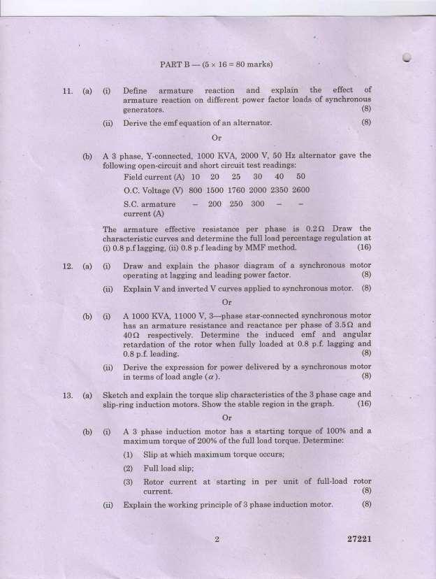
127

128

129

130

131

132

133

134

135

136

137

138

139

140

141

142

143

144

145

146

147

148 ANNA UNIVERSITY, CHENNAI -25. OFFICE OF THE CONTROLLER OF EXAMINATIONS RULES OF THE EXAMINATIONS A candidate is permitted to use geometric tools, non-programmable calculators and approved tables and data books only during the theory and the practical examinations. No other material/gadget (including cell phone) should be brought inside the examination hall. A candidate should neither possess/refer any forbidden material in any form nor should seek/obtain assistance in any form from any person/source towards answering the questions during the examinations. He/she should not assist other candidates in any form towards answering the questions during the examinations. The candidate should not reveal his/her identity in any form in the answer scripts. The candidate should not indulge in canvassing either directly or indirectly to award more than deserving marks in the exanimations. The candidate should maintain discipline and decorum during the examinations. Violation of the above rules in any form during the examinations will attract punishment ranging from levying fine to permanently debarring the candidate from continuing his/her studies as given below. Sl.No. Nature of Malpractice Maximum Punishment 1 Appeal by the candidate in the answer script to show mercy by way of awarding more than deserving marks. 2 The candidate writing his/her name in the answer script. 3 The candidate writing his/her registration number/college name in places other than specified in the answer script 4 5 Any special marking in the answer script by the candidate. The candidate communicating with neighboring candidate orally or nonverbally; the candidate causing suspicious movement of his/her body. Fine of Rs. 1000/- per subject. 6 Irrelevant writing by the candidate in the answer script. 7 The candidate marking on the question paper or writing answer on his/her question paper or making use of his/her question paper for rough work 9 The Candidate facilitating the other candidate(s) to copy from his /her answer script
149 The candidate possessing any incriminating material(s) (whether used or not). For example:-written or printed materials, bits of papers containing written information, writings on scale, calculator, handkerchief, dress, part of the body, Hall Ticket, etc. The candidate possessing cell phone(s)/programmable calculator(s)/any other electronic storage device(s) gadgets and containing incriminating materials (whether used or not). The Candidate possessing the question paper of another candidate with additional writing on it. The candidate passing his/her question paper to another candidate with additional writing on it The candidate passing incriminating materials brought into the examination hall in any medium (hard/soft) to other candidate(s). The candidate copying from neighbouring candidate. The candidate taking out of the examination hall answer booklet(s), used or unused Appeal by the candidate in the answer script coupled with a promise of any form of consideration. Candidate destroying evidence relating to an alleged irregularity. Invalidating the examinations of the subject concerned and all the theory and the practical subjects of the current semester registered by the candidate. Further the candidate is not considered for revaluation of answer scripts of the arrearssubjects. If the candidate has registered for arrears subjects only, invalidating the examinations of all the arrears subjects registered by the candidate. Invalidating the examinations of the subject concerned and all the theory and the practical subjects of the current semester registered by the candidate. Further the candidate is not considered for revaluation of answer scripts of the arrearssubjects. If the candidate has registered for arrears subjects only, invalidating the examinations of all the arrears subjects registered by the candidate. Additional Punishment: if the candidate has not completed the programme, he/she is debarred from continuing his/her studies for one year i.e., for two subsequent semesters. However the student is permitted to appear for the examination in all the arrears-subjects up to the last semester during the debarred period. if the candidate has completed the programme, he/she is prevented from writing the examinations of the arrears-subjects for two subsequent semesters.
150 Vulgar/offensive writings by the candidate in the answer script. The candidate possessing the answering script of another candidate The candidate passing his /her answer script to another candidate Involved in any one or more of the malpractices of serial no. 8 to 21 for the second or subsequent times. The candidate substituting an answer book let prepared outside the examination hall for the one already distributed to the candidate The candidate indulge in any disruptive conduct including, but not limited to, shouting, assault of invigilator, officials or students using abusive and /or threatening language, destruction of property. The candidate harass or engage others to harass on his/her behalf an invigilator, official, witnesses or any other person in relation to an irregularity by making telephone calls, visits, mails or by any other means. Candidate possessing any firearm/weapon inside the examination hall. 27 Cases of Impersonation Invalidating the examinations of all the theory and practical subjects of the current semester and all the arrears subjects registered by the candidate. Invalidating the examinations of all the theory and practical subjects of the current semester and all the arrears subjects registered by the candidate. Additional Punishment: If the candidate has not completed the programme, he/she is debarred from continuing his/her studies for one year i.e., for two subsequent semesters. However the student is permitted to appear for the examination in all the arrears-subjects up to the last semester during the debarred period. If the candidate has completed the programme, he/she is prevented from writing the examinations of the arrears-subjects for two subsequent semesters. Invalidating the examinations of all the theory and practical subjects of the current semester and all the arrears subjects registered by the candidate. Additional Punishment: if the candidate has not completed the programme, he/she is debarred from continuing his/her studies for two years i.e., for four subsequent semesters. However the student is permitted to appear for the examination in all the arrears-subjects up to the last semester during the debarred period. if the candidate has completed the programme, he/she is prevented from writing the examinations of the arrears-subjects for four subsequent semesters. (i)handing over the impersonator to the police with a complaint to take appropriate action against the person involved in the impersonation by the Chief Supt. (ii)if a student of this University is found to impersonate a bonafide student, the impersonating student is debarred from continuing his/her studies and writing the examinations permanently. He/she is not eligible for any further admission to any programme of the University. (iii)debarring the bonafide student for whom the impersonation was done from continuing his/her studies and writing the examinations permanently. He/she is not eligible for any further admission to any programme of the University. CONTROLLER OF EXAMINATIONS
151 College / Department norms OD norms for Students 1. HODs are permitted to grant On Duty for those students attending events like paper presentation in student technical symposium, paper presentation in National / International Conferences, participating in quiz programme, project contest, workshops, placement programmes, seminar, sports etc. 2. Students should submit the filled in OD form, signed by student counselor or class coordinator to the concerned HODs (Second, Third and Final year students of B. E / B. Tech degree courses, and all PG courses). Such requisition should be submitted at least a day before availing the OD. 3. Students should submit the evidence for attending the event (copies of Certificate of attendance, Train Ticket, Bus ticket etc.) within one week after the OD applied, failing which the OD requisition submitted will be cancelled. 4. Students should submit parents undertaking, in case of the students attending the above events, other than the local colleges (beyond 50 km). Girls students should be accompanied by the parents, in case of their participation in the events as listed above, other than the local colleges (beyond 50 km). 5. Students should maintain discipline while attending events in other colleges. It is the responsibility of the students and the parents to maintain discipline throughout, while attending the events as listed above in other colleges. Indiscipline activities, if any, as reported by other colleges, the college will take necessary discipline action leading to suspension of the students from the college. Such reports will be communicated to Anna University and such students will not be permitted to write the Anna University Examination, till the clearance obtained from the college concerned and Anna University. Hence students are to be cautious while attending such events as listed above. 6. It is the responsibility of the students to check whether the OD applied was approved and to check the college website whether the OD applied was properly marked. Discrepancy, if any, should be reported within 10 days (in written to HOD), otherwise the OD applied will not be considered. 7. HODs / class coordinator / student counselors / staff recommending the students to apply for paper presentation, to ensure that the papers are reviewed properly, and to assure that quality paper is submitted based on student s own contribution (they should check paper submitted are not copied from internet, repeated work, plagiarism etc.). 8. If the students are not physically presented in the class, they should be marked as absent, even though he or she attending a program inside the college. He or She should get prior permission from the staff concerned while attending such programme. However, he or she should submit a letter to the concerned staff to give attendance before attending such programme. 9. For calculation of internal assessment mark, student s attendance including OD applied will be considered. Hence students should request the concerned staff members to grant OD and such OD requisition should be updated in the concerned faculty attendance cum assessment record (within 10 days after availing OD). 10. HODs may assign the department faculty / clerk / Lab assistant for proper filing of the OD applied by the students for future reference. 11. First year students are not to be granted OD, unless it is extremely essential. 12. Attendance, OD of students are valuable records for future reference, all faculty and HODs are to ensure that such attendance and OD are properly registered / recorded so as to avoid any kind of discrepancy.
152 K.L.N.COLLEGE OF ENGINEERING DEPARTMENT OF ELECTRICAL & ELECTRONICS ENGINEERING ON DUTY REQUISITION FORM STUDENTS TO ATTEND SKILL DEVELOPMENT PROGRAMMES (Workshop / Seminar / Symposium etc.) To, The Principal, KLNCE. Pottapalayam. Respected Sir, Sub.: Request for OD to attend Date: (Workshop / Conference / Value added course / Symposium / Project Contest / Seminar / Certificate Course / Inplant training / Internship) As, I am going to attend conducted by (Venue & Place) from to. Please permit me to attend the programme and also grant me O.D. for these days. S. No Roll No. Name & Degree, Semester / Section) No. of Programmes already attended & Days OD availed No. of Arrears in AU Exam No. of subjects failed in Class Test No. of Subjects failed in CIT s ATT % As on Sign Discipline / misbehavior, reported if any : Clash with Internal test if any : Recommended by Class co-ordinator HOD OD Permitted OD Approved
153 K.L.N. COLLEGE OF ENGINEERING, Pottapalayam (11 km from Madurai City) STUDENTS LEAVE APPLICATION FORM Department of Electrical and Electronics Engineering Date: Name of the Student: Roll No. : Sem / Sec. : Details of leave availing / applied: Date & Day: No. of. Days (a): Reason for Leave : No. of days, leave & OD, already availed (b): Total. No. of. Days (a+b): % of Attendance as on : is Signature of the Student Name, Mobile No. & Signature of Parent / Guardian Recommended / Not Recommended Class Coordinator HOD/EEE


154 A Brief History of the College K.L.N. College of Engineering is the first self-financing Co-educational Engineering College in Madurai, started in 1994 by Munificence of Philanthropist and well-wishers in Sourashtra Community which is a linguistic minority in Tamilnadu. This college is sponsored by the committee of eminent industrialists and academicians led by enthusiastic, educationalist and industrialist (Late) Thiru K.L.N. Krishnan. This college has the approval of All India Council for Technical Education, New Delhi and is affiliated to Anna University, Chennai. Thiru. K.L.N. Krishnan, Founder President of this Engineering College has rendered Yeoman service to Sourashtra Arts & Science College and Sourashtra Girls Higher Secondary School, Madurai for the past several years. He also promoted a Polytechnic under the name of K.L. Nagaswamy Memorial Polytechnic College in Viraganur, Madurai in This Engineering College, functioned in the premises of the above polytechnic during the academic years & was shifted to its own premises in the year (Late) Thiru K.L.N. Krishnan is the Founder President, and the college is now under the management of Dr. K.N.K. Ganesh as Secretary & Correspondent and other executive committee members. Campus : This college is situated on the South Eastern outskirts of Madurai, 11th Km on Madurai Nedungulam Road. It is built in an area of 53.8 acres. The Campus has multistoried buildings consisting of well provided class rooms, drawing halls, seminar halls, conference hall, library, Air-Conditioned Computer centres, staff rooms and student rest rooms. The infrastructure also consists of five double storeyed laboratory buildings and three single storeyed workshops and Machine shop, and an automobile workshop. The Administrative block (2 storeyed) of 1,185 sq. metre with office in the ground floor, I.T. laboratory in the first floor & class rooms in the second floor has been constructed on the eastern side. A two storeyed block of 1,185 sq. metre consisting class room has been constructed on the southern side of the administrative block. A two storeyed block of 1,185 sq. metre with EIE laboratory in the ground floor, DSP laboratory in the first floor & class rooms in the second floor has been constructed on the western side of the administrative block. A two storeyed block of 2,122 sq. metre with spacious library, video library & Electronic resource section in the ground floor, class rooms in the first floor & CSE laboratory in the second floor has been constructed near the administrative block. A single storeyed block of 1,193 sq. metre with S.M. laboratory in the ground floor CAD, CAM laboratories in the first floor & class rooms in the second floor has been constructed on the north western side of the administrative block. Three Mechanical sheds (occupied by three Mech. Engg. Laboratory) of 2460 sq. metre have been constructed on the northern side of the mechanical block.an automobile work shop of 2304 sq. metre has been constructed on the north western side of the administrative block. An Indoor stadium cum Auditorium of 2,221 sq. metre has been constructed on the northern side of the administrative block. A separate double storeyed post-graduate block of 4,020 square metre for M.B.A. and M.C.A. departments has been constructed on the South Western side of the administrative Block.


155 A single storeyed block of two canteens with 2,485 square metre in the ground floor and ladies rest room in the first floor has been contructed on the south western side of the Administrative Block. A single storeyed block of 1,289 square metre for Electrical & Electronics Engg., Laboratories & class rooms in the ground floor and Electronics & Communication Laboratory and Class rooms in the first floor has been constructed on the western side of the Administrative Block. A two-storeyed block with an area of 2,956 sq. metre has been constructed as an extension to Block III Opposite the U.G. library Block. This block comprised Physics lab, Chemistry lab and EIE Lab. D.S.P. Lab & Class rooms. A two-storeyed block with an area of 2076 squremetre for the use of EEE Dept. in the ground floor & ECE Dept. in the first & 2nd floors is now under construction as an extension to the existing EEE & ECE block on the western side of the administrative block. A two storeyed block with an area of 2,977 sq. metre for the use of Mechanical & Automobile depts. is now under construction, as an extension to the existing Mechanical block on the North- Western side of the administrative block. A separate building with ground floor of area of 170 sq. metre for the installation of Generator on the Southestern side (Opposite to the Vinayagar temple) of the administrative block is under construction & (nearing completion) In order to facilitate the easy accessibility for the students, in all, 950 numbers of computers have been installed so far. This sounds the management s conviction in providing essential infrastructure for the learning purpose in our college. An overhead Tank of 20,000 Litre Capacity at a height of 40 feet has been constructed at a cost of Rs.4 lakhs, donated by Rotary international, Rotary District-1240, Rotary club of LEIGH-ON-SEA. Treated drinking water plant at a cost of Rs.2 lakhs has been installed near the overhead tank. Well-furnished Men s Hostel, Mess block and canteen block are also inside the campus. The college is a quiet retreat, ideal for concentrated study, away from distractions and disturbances of a large city. A single storeyed block of 1,330 square metre with a spacious dining hall in the ground floor and 13 rooms in the first floor for men students has been constructed on the northern side of the administrative block and is already in use. A two storeyed hostel block of 2,034 square metre adjacent to the existing hostel for men students has been constructed. Total expenditure incurred so far towards the cost of equipments& buildings & other assets is about Rs crores. A VINAYAGAR Temple on the eastern side of the administrative Block has been constructed Eight class rooms for I year B.E. / B.Tech 2 class room for M.E. (P.S.) students, and two staff rooms have been constructed in the ECE/EEE block. A Ladies Hostel of 1460 sq.m. which can accommodate about 150 students in under construction within the campus.
156 SALIENT FEATURES OF THE DEPARTMENT 1. GENERAL Started offering B.E. in Electrical and Electronics Engineering in the year 1994 with an intake of 40 (No /RC/94, dated 11th August 1994, AICTE) with the latest intake of 120 in 2011 (F.No.Southern/ /2011/EOA, dated , AICTE). Started offering M.E. in Power Systems Engineering in the year 2005 with an intake of 20 and increased intake to 24 in 2012 (F.No.Southern/ /2012/EOA, dated , AICTE). Accredited in March 2004 (First time F.No.NBA/ACCR-242/2003, dated 24/03/04) and Reaccredited (Second time F.No.NBA/ACCR-242/2003, dated July 19, 2008) by National Board Accreditation,NewDelhi. Re-accredited (Third time - For 2 years w.e.f ) by National Board Accreditation, New Delhi. Re-accredited (Fourth time For 3 years w.e.f. July 2016, upto , F.No /20100-NBA, dated ) by National Board Accreditation, New Delhi. Recognized Research Centre No , Approved by Anna University, Chennai with effect from December 2012, offering guidance for M.S & Ph.D.(Full time/part time) (Renewed upto December 2018, Lr.No. 4904/IR/EEE/AR1 dated ). Both UG and PG programs are permanently affiliated to Anna University, Chennai with effect from December MODROB fund of Rs.5 lakhs was allotted for the year for the Power Electronics laboratory (No.8024/RIFD/MOD-131(pvt)/Policy-III/ , dated ). Department of Science and Technology (DST), sanctioned financial assistance of 19,75,800-/- for the project entitled Smart Meter for measuring Power Quality Disturbances using GSM Technology, Dr.K.Gnanambal, Professor/EEE is the Principal Investigator (Ref. No. IDP/IND/4/2015 dated ). 2. INFRASTRUCTURE Electrical machines laboratory, Control, Measurement and Instrumentation laboratory, Power Electronics laboratory, Electric circuits and Electronic devices laboratory, Research and Development laboratory and Power System Simulation Laboratory are equipped with machineries, components, signal generating, power supply measuring, recording instruments and computer systems costing Rs.2 crores. The total built up area of laboratories is sq.m. Latest softwares on Power system analysis, Power system stability, Power world simulator and Power electronics are available to study, solve, design and simulate research on Power system and Power Electronics problems to experience the real time results. All the class rooms are equipped with computer systems, LCD and OHP to promote the Teaching- Learning process more effectively. Separate library facility for EEE students with more than two thousand books on core subjects and hard copies of IEEE Journals and magazines from 1999 are available for reference. Staff and students can access the softcopy of Journals, proceedings published by IEEE, Elsevier, ASME, Springer, Mc Graw Hill. All laboratories are provided with sufficient computing facilities, printing facility with internet connection to simulate laboratory experiments. 3. STAFF Teams of well qualified, and experienced 31 faculties with cadre ratio as per AICTE, are guiding the students to attain the best educational objectives. Excellent research environment promotes the staff and students to participate, present and publish their research works in the National/International Journals and National/International conferences. Facility and experienced faculty available for guiding Ph.D.scholars. Staff development Programme / Faculty development programme / Workshop/ Seminar are organized regularly to share the knowledge of our experienced faculty with parent institution and other colleges staff and students and Industrial persons. 4. RESEARCH AND DEVELOPMENT The Research and Development section is doing research on Industrial Power Harmonics and mitigation and interact with industries in measuring, recording, analyzing and designing of filters for reducing harmonics with the help of Power Quality analyzer, as per IEEE standard. 5. STUDENTS Students secured 99 University Ranks in B.E.-EEE (1998 to 2016) and 17 University Ranks in M.E.-Power Systems Engineering (2007 to 2016) with Gold medal in 2000 (UG - EEE) and in
157 2011 (PG Power Systems Engineering). Sweety Jain of batch student secured 2nd rank in Anna University Examination in 2009 among 8500 students who completed degree and out of 240 Engineering colleges all over Tamil Nadu. IEEE student s chapter which was started in the year 1999, continuously conducting number of student technical programme. Guest lecturers from industries have been arranged periodically to promote Industry-Institute Interaction and to bridge the gap between curriculum and latest trend in industry. The college received appreciation award for IEEE Student Chapter Activities from IEEE, Madras Section for the year 2015 and The EEE department recognized as IEI Best Division Award for the Academic year To promote innovation, latest trends in industry and employability skills, student s professional activities are conducted every year in the name of symposium and conferences. Workshop/Seminar is regularly conducted for students to meet out the curriculum objectives. Inplant trainings are arranged for second and third year students to have hands on training with industry. Industrial visits are arranged every semester to know about the various process taking places in industry. Placement oriented training programme were conducted every semester right from the first year to develop soft skills, attitude, aptitude, self confidence, communication skills, interview skills etc, so as to face the campus placement programme organized by the college. Professional Trainers from software companies, Bangalore, Chennai are being invited for such training programme..
158 K.L.N. COLLEGE OF ENGINEERING, POTTAPALAYAM DEPARTMENT OF ELECTRICAL AND ELECTRONICS ENGINEERING S.No. Name of the Faculty Designation Mobile No. id 1. Dr.S.M.Kannan Professor & Head Dr.S.Venkatesan Professor Dr.K.Gnanambal Professor - gnans_balu@rediffmail.com 4. Dr. S.Parthasarathy Professor sarathy_sps@yahoo.co.in 5. Dr. S.Venkatanarayanan Professor venjey@yahoo.co.uk 6. A.Marimuthu Associate Professor marimuthu_a@yahoo.com 7. P.Loganthurai Associate Professor loganthurai@yahoo.co.in 8. M.Jegadeesan Associate Professor m_jegadeesan07@rocketmail.co 9. A.S.S.Murugan Associate Professor assm17174@yahoo.co.in 10. S.Manoharan AP(Sr.Gr.) sharpmano@yahoo.com 11. M.GaneshKumari AP(Sr.Gr.) - gnshkumari@gmail.com 12. M.Jeyamurugan AP(Sr.Gr.) jeyam3182@gmail.com 13. K.R.Jeyavelumani Assistant Professor - krjeya35@gmail.com 14. M.Balamurugan Assistant Professor murugan.bala10@gmail.com 15. T.Gopu Assistant Professor gopu70@gmail.com 16. R.JeyapandiPrathap Assistant Professor jprathap03@gmail.com 17. S.Rajalingam Assistant Professor rajalingamrcet@gmail.com 18. N.VimalRadhaVignesh Assistant Professor nvimalvignesh@gmail.com 19. A.Manoj Assistant Professor manojhails@gmail.com 20. R.Jeyarohini Assistant Professor - rjreee2008@gmail.com 21. R.C.Hemesh Assistant Professor On study leave 22. S.P.Rajaram Assistant Professor ramraja798@gmail.com 23. E.Jeyasri Assistant Professor - jeyasrieswaran@gmail.com 24. A.P.S.Ramalakshmi Assistant Professor - ramalakshmi.aps@gmail.com 25. V.Sindhu Assistant Professor - savisindhu@yahoo.co.in 26. R.Divya Assistant Professor - divyaraajagopal@gmail.com 27. R.Sridevi Assistant Professor - sridevirs87@gmail.com 28. M. Bharani lakshmi Assistant Professor - bharanilakshmi.m@gmail.com 29. J.Sangeetha Assistant Professor - geetha_maniraj@yahoo.com 30. M.Maha Lakshmi Assistant Professor - mmahalakshmi36@gmail.com 31. Dr. C.Vimala Rani Assistant Professor - jaysanjayvim@gmail.com
159 Placement Activity Remainder 1. In the month of October every first year students must fill forms online in TATA CONSULTANCY SERVICES (TCS) campus recruitment using nextsteptcs.com website and must submit the following documents in the department. a. SSLC and HSC mark sheet photo copy at least 5. b. Latest passport size Photo at least 5. c. Current address proof with parent contact cell numbers. d. Create your own two id using Gmail. e. Resume with Scanned copy of passport size Photo. f. CT number registered in the TCS website. 2. Every semester end update CGPA in your resume and TCS profile. 3. An Engineering student from Electrical and Electronics Engineering should complete the following courses in order to enhance their software skills. This will be most helpful during their successful completion in Curriculum during 4 th Semester and in the software company campus recruitment. a. Should complete C Programming before joining 2 nd Semester. b. Should complete C++ Programming before joining 3 rd Semester. c. Should complete JAVA Programming before joining 4 th Semester. (for the successful completion of object oriented Programming theory paper and laboratory during 4 th Semester) 4. An Engineering student from Electrical and Electronics Engineering should complete the Micro Processor, Micro Controller and Embedded Systems courses before joining 5 th Semester in order to enhance their Hardware skills. This will be most helpful during their successful completion in Curriculum from 5 th to 6 th Semester and in the Core company campus recruitment. (for the successful completion of Micro Processor and Micro Controller theory as well as laboratory during 5 th Semester and Embedded Systems during 6 th Semester) 5. From 6 th Semester Summer vacation onwards all should prepare for GATE Examination because all Engineering students from Electrical and Electronics Engineering should appear GATE Examination in order to settle in their life by pursuing higher education in the reputed colleges like IIT, NIT and Anna University or else to join as a Graduate Engineer trainee in a public sector companies like IOC, BHEL, PGCI etc., 6. Before joining 7 th Semester all should get any international certification programme course like OCJP, CCNA, etc., and upload the certification details in TCS campus commune website. This will be most helpful during the TCS campus and other MNC company recruitment.
160 Activity TCS Online form Filling in nextsteptcs.com Documents to be submitted in the EEE Department/ Placement Coordinator In the month of October Semester a. SSLC and HSC mark sheet photo copy at least 5. b. Latest passport size Photo at least 5. c. Current address proof with parent contact cell numbers. d. Create your own two id using Gmail. e. Resume with Scanned copy of passport size Photo. f. CT number registered in the TCS website. Updating CGPA in resume and TCS online profile C Programming C++ Programming JAVA Programming Micro Processor & Micro Controller Embedded Systems GATE / UPSC/ TNPSC Preparation International Certification OCJP / CCNA K.L.N. COLLEGE OF ENGINEERING DEPARTMENT OF ELECTRICAL & ELECTRONICS ENGINEERING All India Installed Capacity (in MW) of Power Stations
 includes small hydro projects, wind, solar, tidal, biomass and urban & industrial waste power.")
161 This is a list of states and territories of India by installed capacity of power utilities with electricity generation mode break-up as on 30 April 2016 with figures in Megawatts. REVISED '*'Renewable Energy Sources (RES) includes small hydro projects, wind, solar, tidal, biomass and urban & industrial waste power. Advanced Training Institute Skill Development and Entrepreneurship Programmes Ref: Advanced Training Institute,
Department of EEE, PSNA CET
 EE6501 POWER SYSTEM ANALYSIS L T P C 3 0 0 3 UNIT I INTRODUCTION 9 Need for system planning and operational studies basic components of a power system.- Introduction to restructuring - Single line diagram
SYLLABUS WEEKLY SCHEDULE V SEMESTER DEPARTMENT OF EEE IV YEAR DEGREE COURSE
 VELTECH MULTI TECH Dr RANGARAJAN Dr. SAKUNTHALA ENGINEERING COLLEGE (Owned by Vel Trust 1997) (An ISO 9001: 2008 Certified Institution) Accredited By NAAC with A Grade and NBA Accredited Institution (Approved
Academic Course Description
 BEE305- ELECTRICAL MACHINES Academic Course Description BHARATH UNIVERSITY Faculty of Engineering and Technology Department of Electrical and Electronics Engineering BEE305- ELECTRICAL MACHINES Third Semester,
YMCA UNIVERSITY OF SCIENCE AND TECHNOLOGY, FARIDABAD SCHEME OF STUDIES & EXAMINATIONS B.TECH 3 rd YEAR (SEMESTER V) ELECTRICAL ENGINEERING ( )
 ELECTRICAL ENGINEERING ( )") YMCA UNIVERSITY OF SCIENCE AND TECHNOLOGY, FARIDABAD SCHEME OF STUDIES & EXAMINATIONS B.TECH 3 rd YEAR (SEMESTER V) ELECTRICAL ENGINEERING (2017-18) Sl.No. Course code. Course Title L T P Credits CAT code
YMCA UNIVERSITY OF SCIENCE AND TECHNOLOGY, FARIDABAD SCHEME OF STUDIES & EXAMINATIONS B.TECH 3 rd YEAR (SEMESTER V) ELECTRICAL ENGINEERING (2017-18) Sl.No. Course code. Course Title L T P Credits CAT code
Course Name: POWER ELECTRONICS Course Code: EE603 Credit: 4
 Course Name: POWER ELECTRONICS Course Code: EE603 Credit: 4 Prerequisites: Sl. No. Subject Description Level of Study 01 Basic Electronics p n junction, Diode, BJT, MOSFET 1 st Sem, 2 nd Sem 02 Circuit
Electrical Power Systems
 Electrical Power Systems Analysis, Security and Deregulation P. Venkatesh B.V. Manikandan S. Charles Raja A. Srinivasan Electrical Power Systems Electrical Power Systems Analysis, Security and Deregulation
Academic Course Description
 BME 503 FLUID POWER SYSTEMS Academic Course Description BHARATH UNIVERSITY Faculty of Engineering and Technology Department of Mechanical Engineering BME 503 FLUID POWER SYSTEMS Fifth Semester, 2015-16
K.L.N. COLLEGE OF ENGINEERING DEPARTMENT OF ELECTRICAL AND ELECTRONICS ENGINEERING Course Outcomes, PO & PSO Mapping Regulation 2013
 S.NO K.L.N. COLLEGE OF ENGINEERING DEPARTMENT OF ELECTRICAL AND ELECTRONICS ENGINEERING Course Outcomes, PO & PSO Mapping Regulation 2013 SEMESTER ANNA UNIVERSITY, CHENNAI - AFFILIATED INSTITUTIONS R 2013
GUJARAT TECHNOLOGICAL UNIVERSITY, AHMEDABAD, GUJARAT COURSE CURRICULUM. Course Title: D C MACHINES AND TRANSFORMER (Code: )
") GUJARAT TECHNOLOGICAL UNIVERSITY, AHMEDABAD, GUJARAT COURSE CURRICULUM Course Title: D C MACHINES AND TRANSFORMER (Code: 3330902) Diploma Programme in which this course is offered Electrical Engineering
GUJARAT TECHNOLOGICAL UNIVERSITY, AHMEDABAD, GUJARAT COURSE CURRICULUM Course Title: D C MACHINES AND TRANSFORMER (Code: 3330902) Diploma Programme in which this course is offered Electrical Engineering
GUJARAT TECHNOLOGICAL UNIVERSITY, AHMEDABAD, GUJARAT. Course Curriculum. D C MACHINES AND TRANSFORMERS (Code: ) Electrical Engineering
 Electrical Engineering") GUJARAT TECHNOLOGICAL UNIVERSITY, AHMEDABAD, GUJARAT Course Curriculum D C MACHINES AND TRANSFORMERS (Code: 3330902) Diploma Programme in which this course is offered Semester in which offered Electrical
GUJARAT TECHNOLOGICAL UNIVERSITY, AHMEDABAD, GUJARAT Course Curriculum D C MACHINES AND TRANSFORMERS (Code: 3330902) Diploma Programme in which this course is offered Semester in which offered Electrical
SQA Advanced Unit specification: general information
 SQA Advanced Unit specification: general information Unit title: Electrical Machine Principles Unit code: HT83 47 Superclass: XJ Publication date: August 2017 Source: Scottish Qualifications Authority
Electric Drives Lab PCC 8 EE-456C Electrical Simulation Lab PCC 9 EE-468C Project Workshop SEC
 YMCA UNIVERSITY OF SCIENCE AND TECHNOLOGY, FARIDABAD SCHEME OF STUDIES & EXAMINATIONS B.TECH 4 TH YEAR (SEMESTER VIII) ELECTRICAL ENGINEERING (2017-18) Sl.No. Course code. Course Title L T P Credits CAT
Sl. No. Subject Description Level of Study 01 Power Different types of converters, inverters. 6 th Sem Electronics 02 Power System I& II
 Course Name: Power System III Course Code: EE70A Credit: Prerequisites: Sl. No. Subject Description Level of Study 0 Power Different types of converters, inverters. 6 th Sem Electronics 0 Power System
COURSE: Power Generation and Economics DEPARTMENT: Electrical and Electronics Engineering ACADEMIC YEAR: COURSE CODE: 15EE42 SEMESTER: IV TOTA
 COURSE: Power Generation and Economics DEPARTMENT: Electrical and Electronics Engineering ACADEMIC YEAR: 2016-17 COURSE CODE: 15EE42 SEMESTER: IV TOTAL CONTACT HOURS: 50 hrs. DURATION OF IA: 1 hr. IA MARKS:
AUTO 140A: VEHICLE MAINTENANCE
 AUTO 140A: Vehicle Maintenance 1 AUTO 140A: VEHICLE MAINTENANCE Discipline AUTO - Automotive Technology Course Number 140A Course Title Vehicle Maintenance Catalog Course Description Intended for the incumbent
School of Technology, Energy & Apprenticeship. Advanced Power Engineering Program. Course Outline fall 2014
 School of Technology, Energy & Apprenticeship Advanced Power Engineering Program Course Outline fall 2014 Course Code: OES 7064 Course Title: Electrotechnology, Compression and Refrigeration Prepared By:
Scope for Electrical Machine Design. Objectives. Design and Engineering. Course Description. 23-Dec-16 DESIGN OF ELECTRICAL MACHINES AN OVERVIEW
 SNS COLLEGE OF ENGINEERING (Accredited by NAAC-UGC with A Grade, Approved by AICTE, Recognized by UGC and Affiliated to Anna University, Chennai) COIMBATORE 641 107 DEPARTMENT OF ELECTRICAL AND ELECTRONICS
Cluster Knowledge and Skills for Business, Management and Administration Finance Marketing, Sales and Service Aligned with American Careers Business
 for Business, Management and Administration Finance Marketing, Sales and Service Aligned with American Careers Business About American Careers Correlations The following correlations are provided to demonstrate
Contents. Review of Electric Circuitd. Preface ;
 Preface ; Chapter 1 Review of Electric Circuitd 1.1 Introduction, 1 1.2 Direct Circuit Current, 1 1.2.1 Voltage, 3 1.2.2 Power, 3 1.2.3 Ohm's Law, 5 1.2.4 KirchhofTs Laws, 5 1.2.4.1 Kirchhoff s Current
ELEC 585/462 MOTOR DRIVE DYNAMICS COURSE OUTLINE & ASSESSMENT TECHNIQUES SEPT- DEC / FALL 2013 CRN 11254/11246
 ELEC 585/462 MOTOR DRIVE DYNAMICS COURSE OUTLINE & ASSESSMENT TECHNIQUES SEPT- DEC / FALL 2013 CRN 11254/11246 Instructor: Office Hours: Dr. S. Nandi Days: Any time by appointment Phone: 721-8679 Location:
Higher National Unit Specification. General information for centres. Electrical Motors and Motor Starting. Unit code: DV9M 34
 Higher National Unit Specification General information for centres Unit title: Electrical Motors and Motor Starting Unit code: DV9M 34 Unit purpose: This Unit has been developed to provide candidates with
DHANALAKSHMI SRINIVASAN COLLEGE OF ENGINEERING AND TECHNOLOGY MAMALLAPURAM, CHENNAI
 DHANALAKSHMI SRINIVASAN COLLEGE OF ENGINEERING AND TECHNOLOGY MAMALLAPURAM, CHENNAI -603104 DEPARTMENT OF ELECTRICAL AND ELECTRONICS ENGINEERING QUESTION BANK VII SEMESTER EE6501-Power system Analysis
DEPARTMENT OF ELECTRICAL AND ELECTRONICS ENGINEERING
 DEPARTMENT OF ELECTRICAL AND ELECTRONICS ENGINEERING QUESTION BANK 16EET41 SYNCHRONOUS AND INDUCTION MACHINES UNIT I SYNCHRONOUS GENERATOR 1. Why the stator core is laminated? 2. Define voltage regulation
Course Name: Electric Drives Course Code: EE 701 Credit: 4
 Course Name: Electric Drives Course Code: EE 701 Credit: 4 Prerequisites: Sl. No. Subject Description Level of Study 01 Electrical Machine 02 Power Electronics DC Motor, Induction Motor Rectifier, Inverter(1
University of New South Wales School of Electrical Engineering & Telecommunications ELEC ELECTRIC DRIVE SYSTEMS.
 Aims of this course University of New South Wales School of Electrical Engineering & Telecommunications ELEC4613 - ELECTRIC DRIVE SYSTEMS Course Outline The aim of this course is to equip students with
2010 National Edition correlated to the. Creative Curriculum Teaching Strategies Gold
 2010 National Edition correlated to the Creative Curriculum Teaching Strategies Gold 2015 Big Day for PreK is a proven-effective comprehensive early learning program that embraces children's natural curiosity
GUJARAT TECHNOLOGICAL UNIVERSITY, AHMEDABAD, GUJARAT. Course Curriculum. AUTOMOBILE ELECTRICAL SYSTEM (Code: )
") GUJARAT TECHNOLOGICAL UNIVERSITY, AHMEDABAD, GUJARAT Course Curriculum AUTOMOBILE ELECTRICAL SYSTEM (Code: 3330203) Diploma Programme in which this course is offered Semester in which offered 3 rd Semester
GUJARAT TECHNOLOGICAL UNIVERSITY, AHMEDABAD, GUJARAT Course Curriculum AUTOMOBILE ELECTRICAL SYSTEM (Code: 3330203) Diploma Programme in which this course is offered Semester in which offered 3 rd Semester
University Of California, Berkeley Department of Mechanical Engineering. ME 131 Vehicle Dynamics & Control (4 units)
") CATALOG DESCRIPTION University Of California, Berkeley Department of Mechanical Engineering ME 131 Vehicle Dynamics & Control (4 units) Undergraduate Elective Syllabus Physical understanding of automotive
CATALOG DESCRIPTION University Of California, Berkeley Department of Mechanical Engineering ME 131 Vehicle Dynamics & Control (4 units) Undergraduate Elective Syllabus Physical understanding of automotive
QCF level: 4 Credit value: 15
 Unit 63: Electrical Power Unit code: H/601/1408 QCF level: 4 Credit value: 15 Aim This unit will develop learners understanding of electrical power systems and power distribution and the advantages and
Automotive Technology
 It is the mission of the Automotive Department of Victor Valley Community College to provide quality automotive instruction to a diverse community of students; the array of courses offered shall serve
ACSEP - Applications and Control of Power Electronic Systems
 Coordinating unit: Teaching unit: Academic year: Degree: ECTS credits: 2018 205 - ESEIAAT - Terrassa School of Industrial, Aerospace and Audiovisual Engineering 710 - EEL - Department of Electronic Engineering
ELECTRIC DRIVES N.K. DE P.K. SEN
 ELECTRIC DRIVES N.K. DE P.K. SEN Electric Drives NISIT K. DE Associate Professor Department of Electrical Engineering Indian Institute of Technology Kharagpur and PRASANTA K. SEN Assistant Professor Department
Department of Technology Fall 2004
 Department of Technology Fall 2004 EET 352 ELECTRICAL POWER TECHNOLOGY Instructor: Prof. Vigs Chandra, Ph.D. Telephone: 859-622-1187 E-mail: vigs.chandra@eku.edu Web: http://www.technology.eku.edu/facstaff/chandra/
Using MATLAB/ Simulink in the designing of Undergraduate Electric Machinery Courses
 Using MATLAB/ Simulink in the designing of Undergraduate Electric Machinery Courses Mostafa.A. M. Fellani, Daw.E. Abaid * Control Engineering department Faculty of Electronics Technology, Beni-Walid, Libya
SYNCHRONOUS GENERATOR (ALTERNATOR)
") i SYLLABUS osmania university UNIT - I SYNCHRONOUS MACHINES Constructional Details, Types of Windings, Winding Factors, EMF Equation, Fractional Pitch and Fractional Slot Windings, Suppression of Harmonics
i SYLLABUS osmania university UNIT - I SYNCHRONOUS MACHINES Constructional Details, Types of Windings, Winding Factors, EMF Equation, Fractional Pitch and Fractional Slot Windings, Suppression of Harmonics
JEPPIAAR ENGINEERING COLLEGE DEPARTMENT OF ELECTRICAL AND ELECTRONICS ENGINEERING
 JEPPIAAR ENGINEERING COLLEGE DEPARTMENT OF ELECTRICAL AND ELECTRONICS ENGINEERING VISION OF INSTITUTION To build Jeppiaar Engineering College as an institution of academic excellence in technology and
Power Electronics and Drives (PED)
") Power Electronics and Drives (PED) Introduction Spurred on by technological progress and a steadily increasing concern about the efficient use of depleting energy resources, static power electronic converters
Power Electronics and Drives (PED) Introduction Spurred on by technological progress and a steadily increasing concern about the efficient use of depleting energy resources, static power electronic converters
Computer Aided Transient Stability Analysis
 Journal of Computer Science 3 (3): 149-153, 2007 ISSN 1549-3636 2007 Science Publications Corresponding Author: Computer Aided Transient Stability Analysis Nihad M. Al-Rawi, Afaneen Anwar and Ahmed Muhsin
Three-Phase Motors and Drives
 Unit 63: Three-Phase Motors and Drives Unit code: QCF Level 3: Credit value: 10 Guided learning hours: 60 Aim and purpose K/600/7117 BTEC Nationals This unit aims to give learners knowledge of three-phase
Second Edition. Power Electronics. Devices and Circuits. V. Jagannathan
 Second Edition Power Electronics Devices and Circuits V. Jagannathan Power Electronics Devices and Circuits SECOND EDITION V. Jagannathan Professor and Head Department of Electrical and Electronics Engineering
Instructionally Relevant Alternate Assessments for Students with Significant Cognitive Disabilities
 Instructionally Relevant Alternate Assessments for Students with Significant Cognitive Disabilities Neal Kingston, Karen Erickson, and Meagan Karvonen Background History of AA-AAS as separate from instruction
Question Bank ( ODD)
") Programme : B.E Question Bank (2016-2017ODD) Subject Semester / Branch : EE 6703 SPECIAL ELECTRICAL MACHINES : VII-EEE UNIT - 1 PART A 1. List the applications of synchronous reluctance motors. 2. Draw
Programme : B.E Question Bank (2016-2017ODD) Subject Semester / Branch : EE 6703 SPECIAL ELECTRICAL MACHINES : VII-EEE UNIT - 1 PART A 1. List the applications of synchronous reluctance motors. 2. Draw
Institutional Research and Planning 440 Day Hall Ithaca, New York PULSE Survey
 Institutional Research and Planning 440 Day Hall Ithaca, New York 14853 2009 PULSE Survey The Cornell PULSE (Perceptions of Undergraduate Life and Student Experiences) Survey asks currently enrolled undergraduate
TEE 401: ELECTRO-MECHANICAL ENERGY CONVERSION - II
 TEE 401: ELECTRO-MECHANICAL ENERGY CONVERSION - II Unit I. Synchronous Machine I Constructional features, Armature winding, EMF Equation, Winding coefficients, equivalent circuit and phasor diagram, Armature
Aircraft Electrical Machines
 Unit 73: Aircraft Electrical Machines Unit code: L/600/7210 QCF Level 3: BTEC Nationals Credit value: 10 Guided learning hours: 60 Aim and purpose This unit will provide learners with an understanding
4-Day Power System Analysis, Coordination, System Studies
 4-Day Power System Analysis, Coordination, System Studies Contact us Today for a FREE quotation to deliver this course at your company?s location. https://www.electricityforum.com/onsite-training-rfq Our
: ANIMATION OF A POWER SYSTEM USING POWERWORLD SIMULATOR
 2006-1767: ANIMATION OF A POWER SYSTEM USING POWERWORLD SIMULATOR Frank Pietryga, University of Pittsburgh-Johnstown FRANK W. PIETRYGA is an Assistant Professor at the University of Pittsburgh at Johnstown.
Auto Service Technician
 Auto Service Technician Organization Washburn Institute of Technology Program Number 47.0604 Instructional Level Certificate Target Population Grades 11 & 12 Post-secondary Description The Auto Service
Features of PSEC Educational Programs
 Power Systems & Energy Course 2018 These intensive four-week programs are designed to strike the necessary balance between energy systems engineering theory and relevant, real-world applications. With
Contents. Prefece. List of Acronyms «xxi. Chapter 1 History of Power Systems 1
 Contents Prefece xv Author xix List of Acronyms «xxi Chapter 1 History of Power Systems 1 LI Thomas A. Edison (1847-1931) 5 1.2 Nikola Tesla (1856-1943) 7 1.3 Battle of AC versus DC 8 1.4 Today's Power
SYLLABUS 1. SYNCHRONOUS GENERATOR 9 2. SYNCHRONOUS MOTOR 8
 SYLLABUS 1. SYNCHRONOUS GENERATOR 9 Constructional details Types of rotors emf equation Synchronous reactance Armature reaction Voltage regulation EMF, MMF, ZPF and A.S.A methods Synchronizing and parallel
ELECTRICAL MACHINES. Theory and Practice. M.N. Bandyopadhyay
 ELECTRICAL MACHINES Theory and Practice M.N. Bandyopadhyay ELECTRICAL MACHINES Theory and Practice M.N. Bandyopadhyay Director National Institute of Technology Kurukshetra Delhi-110092 2014 ELECTRICAL
DIRECTORATE OF TECHNICAL EDUCATION DIPLOMA IN ELECTRICAL AND ELECTRONICS ENGINEERING III YEAR M SCHEME V SEMESTER.
 DIRECTORATE OF TECHNICAL EDUCATION DIPLOMA IN ELECTRICAL AND ELECTRONICS ENGINEERING III YEAR M SCHEME V SEMESTER 2015 2016 onwards ELECTRICAL ESTIMATION AND ENERGY AUDITING CURRICULUM DEVELOPMENT CENTRE
Laboratory Experiments for Enhanced Learning of Electromechanical Devices
 Proceedings of 2014 Zone 1 Conference of the American Society for Engineering Education (ASEE Zone 1) Laboratory Experiments for Enhanced Learning of Electromechanical Devices Tomislav Bujanovic and Prasanta
QUESTION BANK SPECIAL ELECTRICAL MACHINES
 SEVENTH SEMESTER EEE QUESTION BANK SPECIAL ELECTRICAL MACHINES TWO MARK QUESTIONS 1. What is a synchronous reluctance 2. What are the types of rotor in synchronous reluctance 3. Mention some applications
EE 842: ELECTRIC POWER SYSTEM IV (3-1-0) Full marks: Theory 100 Sessional=75
 Full marks: Theory 100 Sessional=75") EE 842: ELECTRIC POWER SYSTEM IV (3-1-0) Full marks: Theory 100 Sessional=75 1. Thermal Power Plant: Thermal power plant economical, and ecological. Line diagram of thermal power plant- Boiler: classifications
EE 842: ELECTRIC POWER SYSTEM IV (3-1-0) Full marks: Theory 100 Sessional=75 1. Thermal Power Plant: Thermal power plant economical, and ecological. Line diagram of thermal power plant- Boiler: classifications
Future Trends for Power Systems
 Future Trends for Power Systems A Short Course to Honour Professor David Hill Centre of Excellence in Power Engineering & Australian Power Institute 12 October 2009 Future Trends for Power Systems Happy
Educational qualification:
 hoto S.RAJKUMAR Designation: Assistant Professor (SG) Manakula Vinayagar Institute of Technology, Madagadipet, Puducherry, Pin code 605 107. E mail: rajkumareee@mvit.edu.in Phone: 0413-2680020 Mobile:
ELECTRICAL POWER and POWER ELECTRONICS
 Introduction to ELECTRICAL POWER and POWER ELECTRONICS MUKUND R PATEL (cj* CRC Press Taylor & Francis Group Boca Raton London New York CRC Press is an imprint of the Taylor & Francis Croup, an informa
NZQA registered unit standard version 3 Page 1 of 5. Demonstrate and apply knowledge of electrical machines
 Page 1 of 5 Title Demonstrate and apply knowledge of electrical machines Level 5 Credits 15 Purpose This unit standard covers knowledge and the application of d.c. and a.c. electrical machines for engineers.
Busy Ant Maths and the Scottish Curriculum for Excellence Foundation Level - Primary 1
 Busy Ant Maths and the Scottish Curriculum for Excellence Foundation Level - Primary 1 Number, money and measure Estimation and rounding Number and number processes Fractions, decimal fractions and percentages
Load Test On 3 Phase Slip Ring Induction Motor Lab Manual
 Load Test On 3 Phase Slip Ring Induction Motor Lab Manual Electrical engineering machine lab manual. Brake test on three phase squirrel cage induction motor. No-load &, blocked rotor tests on three phase
Engineering Diploma Resource Guide ST280 ETP Hydraulics (Engineering)
") Engineering Diploma Resource Guide ST80 ETP Hydraulics (Engineering) Introduction Hydraulic systems are a fundamental aspect of engineering. Utilised across a variety of sectors including aviation, construction,
Engineering Diploma Resource Guide ST80 ETP Hydraulics (Engineering) Introduction Hydraulic systems are a fundamental aspect of engineering. Utilised across a variety of sectors including aviation, construction,
Your web browser (Safari 7) is out of date. For more security, comfort and. the best experience on this site: Update your browser Ignore
 is out of date. For more security, comfort and. the best experience on this site: Update your browser Ignore") Your web browser (Safari 7) is out of date. For more security, comfort and Activitydevelop the best experience on this site: Update your browser Ignore Circuits with Friends What is a circuit, and what
Your web browser (Safari 7) is out of date. For more security, comfort and Activitydevelop the best experience on this site: Update your browser Ignore Circuits with Friends What is a circuit, and what
Scholastic s Early Childhood Program Correlated to the Minnesota Pre-K Standards
 Scholastic s Early Childhood Program 5/2/07 Page 1 DOMAIN I: EMOTIONAL AND SOCIAL DEVELOPMENT EMOTIONAL DEVELOPMENT 2. 3. 4. 5. Demonstrate increasing competency in recognizing and describing own emotions
Implementation of Steady-State Power System Visualizations Using PowerWorld Simulator. Dr. Jung-Uk Lim, Department of Electrical Engineering
 A. Title Page Implementation of Steady-State Power System Visualizations Using PowerWorld Simulator Dr. Jung-Uk Lim, Department of Electrical Engineering B. Statement of problem researched or creative
Workshop on Design and Implementation of Power Converters with EMC/EMI Modelling for Micro Grid & Electric Vehicle Applications
 Workshop on Design and Implementation of Power Converters with EMC/EMI Modelling for Micro Grid & Electric Vehicle Applications 18 th - 21 st July 2018 By- Power Electronics Lab (EE Department) Indian
Section details: Direct assessment details: Automatic Transmission and its. applications, hydro static drive and Electric drive
 Section AUTO-A Faculty of Engineering & Technology, SRM University, Kattankulathur 603203 School of Mechanical Engineering Department of Automobile Engineering Course plan Date : 29 Dec. 2011 Course code
2009 Community College of Student Engagement (CCSSE) College Results: Frequency Distributions
 College Results: Frequency Distributions") 2009 Community College of Student Engagement (CCSSE) College Results: Frequency Distributions Institutional Research & Effectiveness Frequency Distributions This report summarizes the observed frequencies
2009 Community College of Student Engagement (CCSSE) College Results: Frequency Distributions Institutional Research & Effectiveness Frequency Distributions This report summarizes the observed frequencies
Simulation of Voltage Stability Analysis in Induction Machine
 International Journal of Electronic and Electrical Engineering. ISSN 0974-2174 Volume 6, Number 1 (2013), pp. 1-12 International Research Publication House http://www.irphouse.com Simulation of Voltage
Scholastic s Early Childhood Program correlated to the Kentucky Primary English/Language Arts Standards
 Primary English/Language Arts Reading (1.2) Arts and Humanities (2.24, 2.25) Students develop abilities to apply appropriate reading strategies to make sense of a variety of print and nonprint texts (literary,
EXPERIMENTAL VERIFICATION OF INDUCED VOLTAGE SELF- EXCITATION OF A SWITCHED RELUCTANCE GENERATOR
 EXPERIMENTAL VERIFICATION OF INDUCED VOLTAGE SELF- EXCITATION OF A SWITCHED RELUCTANCE GENERATOR Velimir Nedic Thomas A. Lipo Wisconsin Power Electronic Research Center University of Wisconsin Madison
Politics Philosophy Economics Undergraduate Degree Plan Curriculum Map New Plan Proposal: Appendix C
 Politics Philosophy Economics Undergraduate Degree Plan Curriculum Map 2016 New Plan Proposal: Appendix C Politics Sub-Plan Learning Outcomes Philosophy Sub-Plan Economics Sub-Plan Politics Sub-Plan (POPE)
DEPARTMENT OF AUTOMOBILE ENGINEERING CURRICULUM. B. Tech. AUTOMOBILE ENGINEERING. In Specialization with MOTORSPORT ENGINEERING
 DEPARTMENT OF AUTOMOBILE ENGINEERING CURRICULUM (Applicable for Students admitted from Academic Year 2015-16) B. Tech. AUTOMOBILE ENGINEERING In Specialization with MOTORSPORT ENGINEERING SCHOOL OF MECHANICAL
A Correlation of. Scott Foresman. Reading Street. Common Core. to the. Arkansas English Language Arts Standards Grade 3
 A Correlation of Scott Foresman Reading Street Common Core 2013 to the To the INTRODUCTION This document demonstrates how Scott Foresman Reading Street Common Core, 2013 meets the. Correlation page references
COMPARISON OF DIFFERENT SOFTWARE PACKAGES IN POWER FLOW AND SHORT-CIRCUIT SIMULATION STUDIES. A Project
 COMPARISON OF DIFFERENT SOFTWARE PACKAGES IN POWER FLOW AND SHORT-CIRCUIT SIMULATION STUDIES A Project Presented to the faculty of the Department of Electrical and Electronic Engineering California State
Electric Power and Energy Systems Engineering Program An Overview. February 10, 2015
 Electric Power and Energy Systems Engineering Program An Overview February 10, 2015 ASU Electric Power and Energy Systems Program ASU has the one of the largest electric power and energy systems programs
ELECTRIC MOTOR DRIVES
 ELECTRIC MOTOR DRIVES Prof. M.S. BERDE Retd. Prof. Department of Electrical Engineering N.I.T. (formerly, MACT) Bhopal (MP) KP KHANNA PUBLISHERS 4575/15, ONKAR HOUSE, OPP. HAPPY SCHOOL DARYAGANJ, NEW DELHI-110002
Electric Machines CHARLES A. GROSS. Aubum University Auburn, Alabama, U.S.A. LßP) CRC Press Vv* / Taylor & Francis Croup. Boca Raton London New York
 CRC Press Vv* / Taylor & Francis Croup. Boca Raton London New York") Electric Machines CHARLES A. GROSS Aubum University Auburn, Alabama, U.S.A. LßP) CRC Press Vv* / Taylor & Francis Croup Boca Raton London New York CRC Press is an imprint of the Taylor & Francis Group,
Electric Machines CHARLES A. GROSS Aubum University Auburn, Alabama, U.S.A. LßP) CRC Press Vv* / Taylor & Francis Croup Boca Raton London New York CRC Press is an imprint of the Taylor & Francis Group,
Charging Battery with Clean Energy
 Charging Battery with Clean Energy By Mr. Raksapol Thananuwong Senior Academic Staff The Institute for the Promotion of Teaching Science and Technology (IPST), Thailand Raksapol Thananuwong BA in Physics
Fuzzy based STATCOM Controller for Grid connected wind Farms with Fixed Speed Induction Generators
 Fuzzy based STATCOM Controller for Grid connected wind Farms with Fixed Speed Induction Generators Abstract: G. Thrisandhya M.Tech Student, (Electrical Power systems), Electrical and Electronics Department,
Department of Electrical and Computer Engineering
 Page 1 of 1 Faculty of Engineering, Architecture and Science Department of Electrical and Computer Engineering Course Number EES 612 Course Title Electrical Machines and Actuators Semester/Year Instructor
B.E-EEE(Marine) Batch 7. Subject Code EE1704 Subject Name Special Electrical Machines
 Batch 7. Subject Code EE1704 Subject Name Special Electrical Machines") Course B.E-EEE(Marine) Batch 7 Semester VII Subject Code EE1704 Subject Name Special Electrical Machines Part-A Unit-1 1 List the applications of synchronous reluctance motors. 2 Draw the voltage and torque
Course B.E-EEE(Marine) Batch 7 Semester VII Subject Code EE1704 Subject Name Special Electrical Machines Part-A Unit-1 1 List the applications of synchronous reluctance motors. 2 Draw the voltage and torque
Solution Manual Power System Analysis And Design Fourth Edition
 Solution Manual Power System Analysis And Design Fourth Edition SOLUTION MANUAL POWER SYSTEM ANALYSIS AND DESIGN FOURTH EDITION PDF - Are you looking for solution manual power system analysis and design
ITT Technical Institute. ET3480T Power Systems Onsite Course SYLLABUS
 ITT Technical Institute ET3480T Onsite Course SYLLABUS Credit hours: 4.5 Contact/Instructional hours: 67 (41 Theory Hours, 26 Lab Hours) Prerequisite(s) and/or Corequisite(s): Prerequisites: ET3380T Power
Electric Power and Energy Systems Engineering Program An Overview. R. Ayyanar 2/17/2016
 Electric Power and Energy Systems Engineering Program An Overview R. Ayyanar 2/17/2016 1 Quiz National Academy of Engineering s selection for the greatest engineering achievement of the 20th Century? Electrification
UNC-Charlotte's Power Engineering Teaching lab
 1 UNC-Charlotte's Power Engineering Teaching lab B. Chowdhury Panel Session Title: Existing and Proposed Power Systems Laboratories for the Undergraduate Curriculum PES GM 2015 2 Outline Background - Energy
PLC Based Closed Loop Speed Control Of DC Shunt Motor
 ISSN: 2454-2377, PLC Based Closed Loop Speed Control Of DC Shunt Motor Mahesh Kumar K M 1 & Dr. P S Puttaswamy 2 1 Assistant Professor, Dept. of Electrical & Electronics Engineering PES College of Engineering,
Advanced Protective Relay Training
 Advanced Protective Relay Training Contact us Today for a FREE quotation to deliver this course at your company?s location. https://www.electricityforum.com/onsite-training-rfq A properly designed protection
CHAPTER 3 TRANSIENT STABILITY ENHANCEMENT IN A REAL TIME SYSTEM USING STATCOM
 61 CHAPTER 3 TRANSIENT STABILITY ENHANCEMENT IN A REAL TIME SYSTEM USING STATCOM 3.1 INTRODUCTION The modeling of the real time system with STATCOM using MiPower simulation software is presented in this
The 2019 International. Future Energy Challenge (IFEC 19)
") Technical Reference Material Updated 28 September 2018 Details in this document supersede other details provided in Call for Proposals and Request For Proposal, and previous updates of this document. The
Technical Reference Material Updated 28 September 2018 Details in this document supersede other details provided in Call for Proposals and Request For Proposal, and previous updates of this document. The
Power Flow Simulation of a 6-Bus Wind Connected System and Voltage Stability Analysis by Using STATCOM
 Power Flow Simulation of a 6-Bus Wind Connected System and Voltage Stability Analysis by Using STATCOM Shaila Arif 1 Lecturer, Dept. of EEE, Ahsanullah University of Science & Technology, Tejgaon, Dhaka,
Government of Karnataka Department of Technical Education Board of Technical Examinations, Bengaluru
 Government of Karnataka Department of Technical Education Board of Technical Examinations, Bengaluru Course Title: POWER ELECTRONICS Course Code : 15EE51T Semester : V Course Group : Core Teaching Scheme
Industrial Controls Training System. Motor Drives. Courseware Sample F0
 Industrial Controls Training System Motor Drives Courseware Sample 87669-F0 A First Edition Published October 2013 2011 by Lab-Volt Ltd. Printed in Canada All rights reserved ISBN 978-2-89640-469-8 (Printed
INSTITUTE OF AERONAUTICAL ENGINEERING Dundigal, Hyderabad
 INSTITUTE OF AERONAUTICAL ENGINEERING Dundigal, Hyderabad - 500 043 MECHANICAL ENGINEERING ASSIGNMENT Name : Electrical and Electronics Engineering Code : A40203 Class : II B. Tech I Semester Branch :
In any of the 5 star hotels. The exact venue will be informed once finalized.
 Training Title ELECTRIC DISTRIBUTION SYSTEM EQUIPMENT: Transformers, Switchgears, Circuit Breakers, Relays, Capacitors, Surge Arresters, Cables & Meters: Operation, Inspection, Testing, Evaluation, Maintenance
Presented at the 2012 Aerospace Space Power Workshop Manhattan Beach, CA April 16-20, 2012
 Complex Modeling of LiIon Cells in Series and Batteries in Parallel within Satellite EPS Time Dependent Simulations Presented at the 2012 Aerospace Space Power Workshop Manhattan Beach, CA April 16-20,
Contents. Preface... xiii Introduction... xv. Chapter 1: The Systems Approach to Control and Instrumentation... 1
 Contents Preface... xiii Introduction... xv Chapter 1: The Systems Approach to Control and Instrumentation... 1 Chapter Overview...1 Concept of a System...2 Block Diagram Representation of a System...3
ECSE-2100 Fields and Waves I Spring Project 1 Beakman s Motor
 Names _ and _ Project 1 Beakman s Motor For this project, students should work in groups of two. It is permitted for groups to collaborate, but each group of two must submit a report and build the motor
Toronto, Ontario, Canada
 Toronto, Ontario, Canada SCHOOL: DEPARTMENT: PROGRAM (If applicable): COURSE TITLE: COURSE CODE: TOTAL COURSE HOURS: PRE-REQUISITES/CO-REQUISITES: COURSE ELIGIBILITY FOR PRIOR LEARNING ASSESSMENT AND RECOGNITION