PowerRouter Unifit. Installation Manual. PowerRouter love your energy. p/n ,A.01 Date:
|
|
|
- Spencer Cook
- 5 years ago
- Views:
Transcription


1 PowerRouter Unifit Installation Manual PowerRouter love your energy p/n ,A.01 Date:

2 Standby Drill template PowerRouter Unifit Drill template PowerRouter Unifit Standby Standby PowerRouter Unifit Installation manual Illustrations 1 2 Drill template PowerRouter Unifit i PowerRouter Read the installation manual for details + mounting bracket 370 mm max. ø 5.5 mm 400 mm max. ø 10 mm A A! A B Max.40 C Min.-10 C 16,5 kg A min. 300 mm B min. 800 mm A 370 mm Installation steps 2x 1 4 x 2 4x x mm max. ø 5.5 mm p/n ,A.01 1
3 Illustrations PowerRouter Unifit Installation manual N L N L Li-ion DATA 1 Fuse 150A Slow Blow 48V +BAT -BAT TMPS GND SH+ SH- SSOR 1 SSOR 1 Export Export kwh kwh Consumption Consumption kwh kwh L1 L2 L3 L1 L2 L3 2


4 PowerRouter Unifit Installation manual Illustrations 5 CAN SSOR 2 Export kwh Consumption kwh Optional SSOR 1 Export kwh Consumption kwh 6 Fuse 315 ma 11 N 1 L1 4 L2 7 L3 9 L3 6 L2 3 L1 1 3


5 Illustrations PowerRouter Unifit Installation manual 7 fuse 315 ma 11 N 1 L1 4 L2 7 L3 9 L3 6 L2 3 L CAN 100 mm 1 9 Fuse 315 ma N L1 L1 4
6 NO NCNO NC NO NCNO NC PowerRouter Unifit Installation manual Illustrations AC GRID AC LOCAL OUT AC GRID AC LOCAL OUT AC grid N L K201/K202 NO NC AC grid N L external relay L N external relay Export kwh N L1 L2 L3 Ripple 100% control receiver N L1 L2 L3 Consumption kwh Export kwh Consumption kwh N L1 L2 L3 N L1 L2 L3 12 5
7 NO NCNO NC Illustrations PowerRouter Unifit Installation manual AC GRID AC LOCAL OUT AC grid AC local out K201/K202 N L N L NO NC external relay 15 1 L N PRA1RLY N L1 L2 L3 2 Export kwh Consumption kwh 5 N L1 L2 L
8 NO NCNO NC PowerRouter Unifit Installation manual Illustrations GND GND GND GND RJ45 Pin# Orange/White Tracer 1 Orange 2 Green/White Tracer 3 Blue 4 Blue/White Tracer 5 Green 6 Brown/White Tracer 7 Brown 8 C A B D AC GRID AC LOCAL OUT AC grid K201/K202 N L NO NC > 300mm CBEU-02 A A CSAP-01 5 mm Export kwh Consumption kwh N L1 L2 L3 4 N L1 L2 L3 7

9 Illustrations PowerRouter Unifit Installation manual


10 PowerRouter Unifit Installation manual Illustrations
11 Illustrations PowerRouter Unifit Installation manual 10
12 PowerRouter Unifit Installation manual Contents Contents Contents Introduction Applicability Symbols used in the documentation Warranty Safety General safety PowerRouter Local Out Public grid Batteries General description PowerRouter Unifit - intended use Internet connection PowerRouter Installation Tool phase grid sensor (required accessory PRA3SSE) phase generation sensor (accessory PRA3GSSE) External relay (accessory PRA1RLY) Wireless Energy Management Kit (accessory PRAxWEMK) Batteries Battery temperature sensor Installation Check the contents of the PowerRouter box Determine the mounting location Mount the PowerRouter Unifit Connect the AC grid Connect the 48V Li-ion batteries Connect the 48V lead-acid batteries Connect the sensors Connect the 3-phase grid sensor (PRA3SSE - required) Connect the 3-phase generation sensor (PRA3GSSE) Connect the external relay (accessory) Connect the external relay for energy management Connect the external relay to isolate the PowerRouter from the public grid Connect the external relay for a backup power supply
13 Contents PowerRouter Unifit Installation manual 4.9 Install the Wireless Energy Management Kit (PRAxWEMK) Connect the additional cable (Italy) Switch on the system Initialise the PowerRouter - Installation Tool Run the selftest (Italy) Connect the PowerRouter to the internet Connect to an internet modem / router Connect via a switch to an internet router Connect to a wireless access point Register the PowerRouter on mypowerrouter.com Register additional PowerRouter systems to a single login Installation Tool Introduction Display settings Back-light Display Language PowerRouter settings Self-use Winter mode Alarm 1 / Alarm Standby Standby timer Grid Country Grid limits EEG Reactive power control Dynamic feed-in limiter Battery pack Battery discharging Battery charging Maintenance charge Operation Display menu Troubleshoot Troubleshooting Check the LED status Check the error messages Error explanation Hard error Soft error Error code
14 PowerRouter Unifit Installation manual Contents 7.5 Errors Procedures Restart the PowerRouter Check the PowerRouter airflow Check the internet connection Look up the firmware versions and id number Reset the PowerRouter De-installation De-installation Disposal Technical specifications Technical specifications - PowerRouter Unifit (Li-ion models) Technical specifications - PowerRouter Unifit (lead acid models)
15 1 Introduction PowerRouter Unifit Installation manual 1 Introduction 1.1 Applicability This installation manual is intended for qualified installation personnel. It describes how you can safely install, connect, start and decommission the following PowerRouter types: PowerRouter Unifit (Li-ion): PR50Bi/S48 PR37Bi/S48 PowerRouter Unifit (Lead acid): PR50B/S48 PR37B/S48 PR30B/S Symbols used in the documentation DANGER This symbol indicates a hazardous situation which, if not avoided, could result in death or serious injury. WARNING This symbol indicates a situation which, if the instructions are not followed, could result in injury and damage to the equipment. This symbol indicates a situation which, if the instructions are not followed, could result in damage to the equipment or malfunctioning. i This symbol indicates additional information to ensure optimal operation of the system. 1.3 Warranty PowerRouter factory warranty conditions Our quality control program ensures that each PowerRouter product is manufactured to exact specifications and is thoroughly tested before leaving the factory. 5 year warranty The Nedap factory warranty period is 5 years from the purchase date of the PowerRouter system. The warranty conditions are based on EU Directive 99/44/EC, without prejudice to any legal rights. Extended warranty For all PowerRouter systems you can acquire a 5-year extension to the PowerRouter factory warranty, for a total of 10 years of warranty coverage. The extended warranty can only be purchased within 6 months of the PowerRouter delivery date. 14
16 PowerRouter Unifit Installation manual 1 Introduction Warranty conditions If a PowerRouter becomes defective during its warranty period, one of the following services will be performed at no charge for materials, but exclusive of labour costs, at the discretion of the PowerRouter Helpdesk: Repair at Nedap N.V. Repair on site Exchange for a replacement unit (of equivalent value according to model and age) Exclusion of liability Warranty claims and liability for direct or indirect damage are excluded if arising from: Transport and storage damage Incorrect installation and/or commissioning Modifications, changes or attempted repairs by untrained and unauthorised personnel Incorrect use or inappropriate operation Insufficient ventilation of the device Failure to observe the applicable safety regulations Force majeure (e.g. lightning, overvoltage, storm, fire) Cosmetic shortcomings which do not influence the functioning of the unit Damage due to moisture and/or other environmental conditions i The installer/dealer who installed the PowerRouter must report the defective PowerRouter system to the PowerRouter Helpdesk. Nedap reserves the right to replace the unit with one having equal or better specifications, at Nedap's judgement. Information for Australian purchasers - Consumer statutory rights In Australia, this warranty is given by, and all Australian warranty claims should be directed to: Nedap Energy Systems Australia 4B/4602 Mitchell Highway Telephone: Lucknow NSW support-au@powerrouter.com The benefits to the consumer given by this factory warranty are in addition to other rights and remedies of the consumer that are stipulated by law, and which are not affected by this factory warranty. Our products come with guarantees that cannot be excluded under the Australian Consumer Law. You are entitled to a replacement or refund for a major failure and for compensation for any other reasonable foreseeable loss or damage. You are also entitled to have the goods repaired or replaced if the goods fail to be of acceptable quality and the failure does not amount to a major failure. Disclaimer All rights to the content of this manual are owned by N.V. Nederlandsche Apparatenfabriek 'Nedap' (hereinafter Nedap). By using this manual you accept the terms of this disclaimer. Nedap has made every effort to ensure that this manual is accurate. Nedap accepts no liability for any inaccuracies or omissions in this manual nor for any damages arising from or related to its use. No data published in this manual may be reproduced or published in any form or by any means without the prior written consent of Nedap. Information in this manual is subject to change without notice and does not represent any commitment on the part of Nedap. Nedap does not assume any obligation to update the information in this manual after publication and reserves the right to make improvements to this manual and/or to the products described in this manual at any time without notice. If you find information in this manual that is incorrect, misleading or incomplete, we would appreciate your comments and suggestions. 15
17 2 Safety PowerRouter Unifit Installation manual 2 Safety 2.1 General safety Before installing or using the PowerRouter, read all of the instructions and alerts on the hardware and in the user and installation manual. WARNING The local output is floating if the system is not connected to the public grid 2.2 PowerRouter There are two markings on the PowerRouter (figure 1): A marking with battery warnings. A type label that provides technical specifications. i The image shows an example of the markings. The markings may be different depending on the PowerRouter type. 2.3 Local Out DANGER The Local Out delivers electrical power (230 V, 50 Hz). WARNING As an extra safety measure it is required that a 2-pole emergency switch is installed at the AC LOCAL OUT connection (if used). This emergency switch must be connected in accordance with the UPS-safety standard. 2.4 Public grid DANGER The AC grid delivers electrical power (230 V, 50 Hz). 16
18 PowerRouter Unifit Installation manual 2 Safety WARNING Before you connect the PowerRouter to the Public AC grid, contact the local utility company. They have to confirm that it is allowed to connect the system. 2.5 Batteries DANGER Batteries deliver electric power and can cause an energy or fire hazard when they are shorted, or incorrectly installed. WARNING Series fuse protection is required for the 48V lead-acid batteries. (48V Li-ion batteries have fuse protection inside.) Batteries must be located in a designated battery area. A battery area must comply with the local regulations.this is because of the dangers of hydrogen gas and battery acid. Explosive gasses. Prevent flames and sparks. Provide adequate ventilation during charging. The battery temperature sensor is installed on the 48V lead-acid batteries. The PowerRouter uses the sensor input to optimise charging of the batteries. When the batteries overheat, the PowerRouter stops charging the batteries. i 48V Li-ion batteries do not need the battery temperature sensor. 17
19 3 General description PowerRouter Unifit Installation manual 3 General description 3.1 PowerRouter Unifit - intended use The PowerRouter Unifit is a battery manager, designed for indoor use. This is a universal retrofit unit to extend any brand of solar inverter or other generation unit to a generation system with battery storage. It can be used for battery storage of generated energy to maximise self-use or to provide backup. For more information visit The PowerRouter is compliant with the following directives: 2004/108/EC (EMI) 2006/95/EC (low voltage directive) The PowerRouter has no serviceable parts inside Internet connection When the PowerRouter is connected to the internet the monitoring tool mypowerrouter.com provides detailed system information (for example performance, battery state of charge) of your PowerRouter. Keep the system up to date with the latest features by remotely updating the PowerRouter to the latest firmware PowerRouter Installation Tool The Installation Tool helps you to initialize the PowerRouter, make advanced settings, and update the PowerRouter firmware if applicable. Before you can use the Installation Tool, you must download and install the tool on your computer. The Installation Tool includes the latest available firmware version, so no additional downloads are required. i You can download the PowerRouter Installation Tool and guideline via the PowerRouter website. You need your login details for this website. You can request login details via Check the website regularly for updates to the PowerRouter Installation Tool phase grid sensor (required accessory PRA3SSE) With the signal from this 3-phase sensor, the PowerRouter determines the energy consumption with the public grid for a 3-phase system. The PowerRouter uses this data to measure the amount of energy which can be stored in the batteries or if any energy is required for consumption from the batteries. With the 3- phase sensor the consumption of the self generated solar energy is maximised. The 3-phase grid sensor can be ordered via your local Business Partner. 18
20 PowerRouter Unifit Installation manual 3 General description phase generation sensor (accessory PRA3GSSE) With the signal from this 3-phase sensor, the PowerRouter determines the amount of energy produced by the generating energy source already installed (solar inverter or other energy source). With the installation of this sensor and connecting the system to internet the complete system can be monitored in one place: mypowerrouter.com. The 3-phase generation sensor can be ordered via your local Business Partner. The two 3-phase sensors are programmed in a different way. In order for the sensor communication to work properly, you need a PRA3SSE and a PRA3GSSE during installation. 3.4 External relay (accessory PRA1RLY) The external relay can be ordered via your local Business Partner. You can use the external relay to: Use energy management (figure 10). If the amount of solar energy fed to the public grid exceeds the programmed value, the PowerRouter can switch on additional loads via the external relay. How long the load stays switched on can be programmed though the advanced settings in the Installation Tool. Isolate the PowerRouter from the public grid by a ripple control receiver (figure 11). The ripple control receiver is not included. The disconnection is according to the German directive EEG2012. Only the disconnect contacts of the relay are used. Setup a backup power supply (figure 13). If the public grid fails, the external relay is energised. The switch over to the local AC grid is done via one of the user-selectable relays (K201 / K202) of the PowerRouter. 3.5 Wireless Energy Management Kit (accessory PRAxWEMK) The Wireless Energy Management Kit (WEMK) can be used with PowerRouter products to support energy management. If the amount of solar energy fed to the public grid exceeds the programmed value, the PowerRouter can switch on additional loads via the WEMK The WEMK is available in several country specific versions and can be ordered via your local Business Partner. The WEMK contains a: Binary input module (Eaton CBEU-02/xx). Wireless plug-in actuator (Eaton CSAP-01/xx). The plugs on this product are country specific. Please order the correct version for your country. 19
21 3 General description PowerRouter Unifit Installation manual 3.6 Batteries The PowerRouter Unifit for Li-ion models function with approved 48V Li-ion batteries. The PowerRouter Unifit for lead acid models function with any 48V lead-acid batteries. Proper settings can be made via the Installation Tool. Never connect 24V lead acid batteries to the PowerRouter Unifit. Always check the specifications of the supplier, before making battery settings. 3.7 Battery temperature sensor The battery temperature sensor must be installed on the 48V lead-acid batteries. The PowerRouter uses the sensor input to optimise charging of the batteries. When the batteries overheat, the PowerRouter stops charging the batteries. Proper settings can be made via advanced settings in the Installation Tool. i 48V Li-ion batteries do not need the battery temperature sensor. 20
22 PowerRouter Unifit Installation manual 4 Installation 4 Installation 4.1 Check the contents of the PowerRouter box The PowerRouter box must contain the following: The PowerRouter Unifit. Manual set for PowerRouter Unifit, including the drill template Wall-mounting bracket. Clip-on ferrite core for the UTP cable (Internet). Cable gland (for installation in Italy). Clip-on ferrite core for the digital input (for installation in Italy). Battery temperature sensor (only for PRxxB/S48) 4.2 Determine the mounting location The installation location of the PowerRouter must meet the following: The PowerRouter must be mounted indoors. Mount the PowerRouter as close as possible to the meter cupboard. Do not mount the PowerRouter in direct sunlight. Do not mount the PowerRouter during periods of precipitation or high humidity (>95%). Moisture trapped within the location may cause corrosion and damage to the electronic components. When the internal temperature is too high, de-rating will occur. The PowerRouter reduces the power output if the internal temperature becomes too high. The location is not accessible for children. The PowerRouter emits a slight hum during operation. This noise is normal and has no effect on performance, but it can be disturbing if the unit is installed on a wall in a living area, on the outside of a wall that is near a living area, or on certain types of materials (thin wood panels or sheet metal). The wall should be within ± 5 vertical. The mounting surface must be able to support the extra weight of the PowerRouter Unifit (16.5 kg). The type information sticker must be visible after mounting the PowerRouter (figure 1). The sticker contains the serial number which is the login code for the Installation Tool and to register at mypowerrouter.com for logging and monitoring. The outside dimensions of the PowerRouter Unifit are 545 x 502 x 149 mm (W x H x D). The PowerRouter must be installed with 300 mm clearance at the top and bottom of the unit. If multiple generation units are stacked there must be 800 mm of clearance between each system. 21
23 4 Installation PowerRouter Unifit Installation manual DANGER Do not mount the PowerRouter on or underneath flammable construction materials. Do not mount the PowerRouter in areas where highly flammable materials are stored. Do not mount the PowerRouter in areas where there is a danger of explosion. WARNING To prevent electric shock or other injury, check for existing electrical or plumbing installations in the walls before drilling the holes for the PowerRouter. Ensure that there is sufficient clearance for the airflow around the PowerRouter! Local regulations may require larger working clearances. If you mount the PowerRouter in a cabinet, closet or other relatively small enclosed area, sufficient air circulation must be provided in order to dissipate the heat generated by the unit. 4.3 Mount the PowerRouter Unifit The PowerRouter is shipped with a wall-mounting bracket that is suitable for use on most walls. To mount the PowerRouter: 1. Use the drill template provided with the PowerRouter to drill the holes for the wall-mounting bracket. (Follow the illustrated instructions on the drill template, figure 2.) 2. Mount the wall-mounting bracket. 3. Mount the PowerRouter Unifit. 4. Open the lower front cover. 5. Mount the additional screws (use a screwdriver with a blade-length of at least 160 mm). 4.4 Connect the AC grid WARNING Before you connect the PowerRouter to the Public AC grid, contact the local utility company. They have to confirm that it is allowed to connect the system. The PowerRouter Unifit and the already installed generation unit can be installed in a 1-phase as well as a 3-phase situation. Please make sure the PowerRouter Unifit and the inverter already installed are on the same phase to prevent load imbalances. 22
24 PowerRouter Unifit Installation manual 4 Installation See figure 3 for the connection overview. 1. Install an AC Disconnect Switch between the PowerRouter and the AC grid. 2. Strip the insulation off the wires. To prevent overheating of the wires, you must use wires with a conductor size of 4 mm Pass the wires through the strain-reliefs at the bottom of the PowerRouter (max. cable length inside connection area of 35mm). 4. Connect the earth ( ) according local regulations. 5. Connect the phase (L) and neutral (N) wire from the AC grid to the AC disconnect switch, and from the AC disconnect switch to the AC GRID terminal on the PowerRouter. 6. Tighten the strain-reliefs with a torque between 4 Nm and 6 Nm. 4.5 Connect the 48V Li-ion batteries See figure 3 for the connection overview. 1. Use battery cables with a cross sectional area of 35 mm 2 to 50 mm 2 and a maximum length of 2.5 m per cable. 2. Strip approximately 25 mm of insulation from the cable. 3. Insert the cable into the terminal of the PowerRouter (red to the positive terminal, black to the negative terminal). 4. Tighten the cable connection with a torque between 15 Nm and 20 Nm. 5. Connect the battery cables to the battery following the manufacturers manual. 6. Insulate the battery poles. 7. Connect a CAT5e UTP cable (or better), between the PowerRouter DATA1 port and the 48V Li-ion battery unit (the maximum length of the UTP cable is 10 m). WARNING Batteries must be located in designated battery areas, and must comply with the local requirements. To prevent overheating of the contacts, you must tighten all screws and bolts according the manufacturers recommendation. Insulate the battery poles to prevent in-advert shorting. Shortened poles may lead to sparks, fire hazard, or damage to the batteries Miswiring can cause damage to the PowerRouter. Read the label on the battery. Always use the directions of the battery manufacturer when installing batteries. Never exchange 48V batteries with 24V batteries. i Check for supported Li-ion batteries. 23
25 4 Installation PowerRouter Unifit Installation manual 4.6 Connect the 48V lead-acid batteries See figure 4 for the connection overview. 1. Install a Battery Disconnect Switch (2-pole isolation) between the PowerRouter and the batteries. Use battery cables with a cross sectional area of 35 mm 2 to 50 mm 2 and a maximum length of 2.5 m per cable. 2. Install a fuse (150 A slow-blow) in series with the positive battery cable. It must be installed on a fixed surface, as close as possible to the battery. 3. Strip approximately 25 mm of insulation from the cable. 4. Insert the cable into the terminal of the PowerRouter (red to the positive terminal, black to the negative terminal). 5. Tighten the cable connection with a torque between 15 Nm and 20 Nm. 6. Use cable lug (eyelet terminal) on the other end of the battery cable. 7. Insulate the battery poles. 8. Clean the surface near the (+) pole where you will place the temperature sensor. 9. Stick the self-adhesive battery temperature sensor onto the battery near the (+) pole. 10. Connect the sensor wires to the TMPS (red wire) and GND (black wire) terminals of the PowerRouter. WARNING Batteries must be located in designated battery areas, and must comply with the local requirements. This is because of a possible build-up of hydrogen gas and battery acid. To prevent overheating of the contacts, you must tighten all screws and bolts according the manufacturers recommendation. Insulate the battery poles to prevent in-advert shorting. Shortened poles may lead to sparks, fire hazard, or damage to the batteries Miswiring can cause damage to the PowerRouter. Read the label on the battery. Always use the directions of the battery manufacturer when installing batteries. Never exchange 48V batteries with 24V batteries. 4.7 Connect the sensors Connect the 3-phase grid sensor (PRA3SSE - required) See figure 5 for the connection overview. The sensor is pre-configured and requires no setup; only hard wiring is required. 1. Disconnect the Public AC grid. 2. Mount the 3-phase grid sensor in the position (no. 1) as shown in figure 5 3. Set the 3-phase grid sensor switch in the 1 Position as shown in figure Connect the 3-phase grid sensor in accordance with the configuration as shown in figure 6 ( 3P.n ). Cable cross-section area: 4 mm 2-16 mm 2. Tighten the screws with a torque between 1.7 Nm and 3 Nm. 24
26 PowerRouter Unifit Installation manual 4 Installation 5. Connect the 1 meter sensor cable to the 3-phase grid sensor (included). a. Green/white wire -> sensor terminal 41. b. Green wire -> sensor terminal 42. c. Orange/white wire -> sensor terminal A CAT5e UTP cable (or better), with a maximum length of 25 meters, may be used to extend the connection (RJ45-connector type: T-568B). 7. Place the ferrite core with one loop in the cable. The ferrite core must be within 10 cm of the PowerRouter. 8. Insert the RJ45 plug at the end of the sensor cable into the PowerRouter CAN port. 9. After initialising (section 4.12), check the PowerRouter display for correct operation of the sensor Service menu Status Sensor. If correct, OK will appear on the display (This may take up to 3.5 minutes after start-up). Make sure the sensor is correctly installed. Incorrect installation will result in no self-use maximization, can damage the sensor or will deplete the battery. For an installation of the sensor in a 1-phase situation, make sure the sensor is connected as shown in figure 9. Terminal 4 must always be powered. For further details on the sensor please refer to the manufacturer s manual Connect the 3-phase generation sensor (PRA3GSSE) See figure 5 for the connection overview. The sensor is pre-configured and requires no setup; only hard wiring is required. The 3-phase generation sensor is installed in a different way as the 3-phase grid sensor. 1. Disconnect the Public AC grid and the generation unit already installed. 2. Mount the 3-phase generation sensor in the position (no. 2) as shown in figure 5 3. Check if the 3-phase generation sensor switch is in the locked Position. 4. Connect the 3-phase generation sensor in accordance with the configuration as shown in figure 7 ( 3P.n ). Cable cross-section area: 4 mm 2-16 mm 2. Tighten the screws with a torque between 1.7 Nm and 3 Nm. 5. Connect the 2 meter sensor cable to the 3-phase generation sensor. a. Green/white wire -> sensor terminal 41. b. Green wire -> sensor terminal 42. c. Orange/white wire -> sensor terminal A CAT5e UTP cable (or better), with a maximum length of 25 meters, may be used to extend the connection (RJ45-connector type: T-568B). 25
27 4 Installation PowerRouter Unifit Installation manual 7. Insert the RJ45 plug at the end of the sensor cable into the splitter delivered with the 3-phase generation sensor. Also connect the UTP cable of the 3-phase grid sensor to the splitter, as shown in figure Place the ferrite core with one loop in the cable. Connect a CAT5e UTP cable (or better) from the splitter to the PowerRouter CAN port. The ferrite core must be within 10 cm of the PowerRouter as shown in figure 8. For an installation of the sensor in a 1-phase situation, make sure the sensor is connected as shown in figure 9. Terminal 4 must always be powered. For further details on the sensor please refer to the manufacturer s manual. 4.8 Connect the external relay (accessory) Connect the external relay for energy management See figure 10 for the connection overview. 1. Connect the external relay. Use one of the user-selectable contacts K201 / K Program the user-selectable contacts K201 / K202 via advanced settings in the installation tool (see chapter 5). The load that is connected to the relay must be 1-phase. i For this function the value for energy export to the grid must be >0, measured by the 3-phase grid sensor Connect the external relay to isolate the PowerRouter from the public grid This option is only applicable for Germany (directive EEG2012). See figure 11 for the connection overview of the external relay Connect the external relay for a backup power supply See figure 13 for the connection overview. 1. Connect the load to the external relay. 2. Strip the insulation off the wires. Use wires with a conductor size of 4 mm². 3. Pass the wires through the strain-relieves at the bottom of the PowerRouter. 4. Connect the phase (L) and neutral (N) wire from the external relay to the AC LOCAL OUT terminal on the PowerRouter. 5. Install an AC Disconnect Switch between the AC local out and the external relay. 6. Tighten the strain-relieves with a torque between 4 Nm and 6 Nm. 7. Connect the external relay control wires. Use one of the user-selectable contacts K201 / K Program the user-selectable contacts K201 / K202 via advanced settings in the installation tool (see chapter 5). 26
28 PowerRouter Unifit Installation manual 4 Installation DANGER The local out output is only suitable for 1-phase loads. Connecting 1-phase of a 3-phase load, may lead to damage to the 3-phase load. Batteries will not be charged if the local out has a continuous load with an average load of 80% of the rated power. If the batteries are not charged they may be severely damaged and the lifetime may be reduced. Make sure the batteries get charged by reducing the connected loads or intermittent use. Connect the earth ( ) according local regulations. 4.9 Install the Wireless Energy Management Kit (PRAxWEMK) See figure 18 for the connection overview and figure 19 for installation details. 1. Open the binary input module. 2. Connect two wires to the connection AA of the binary input module. 3. Fix the location of the wires with a cable tie. 4. Remove the foil (1) from the battery. 5. Press the button (2) once. The LED (3) flashes once and stays on for a few seconds. 6. While the LED is on press the button (2) once. The LED (3) flashes twice and stays on for a few seconds. If the LED is off the configuration is completed. i If the LED flashes three or four times, repeat the step above until the LED flashes twice. 7. Press the button (4) once (<0.5s) to set the wireless plug-in actuator in teaching mode. 8. Short circuit the contacts AA and keep it this way. This simulates activation of the binary input module, the wireless plug-in actuator should make a clicking sound twice (switch on). 9. Press the button (4) once (<0.5s) to set the wireless plug-in actuator in normal mode. 10. Remove the short circuit from the contacts AA. i It is advised to install the Binary input module in a standard mounting box (plastic). 11. Install the binary input module with the double sided tape. The binary input module must be installed at least 300mm away from the PowerRouter. 12. Connect the two wires to the PowerRouter programmable contact K201/K Install the cover on the binary input module. 14. Install the wireless plug-in actuator in the desired wall outlet. 15. Program the contact K201/K202 for energy management (refer to chapter 5). 27
29 4 Installation PowerRouter Unifit Installation manual The maximum load of the wireless plug-in actuator is 8A. The maximum range of the binary input module is 50m. Walls, ceilings and metal constructions will limit the range. (For details refer to the manuals delivered with the binary input module and wireless plug-in actuator.) i For this function the value for energy export to the grid must be >0, measured by the 3-phase grid sensor. Additional xcomfort products that can be ordered at Eaton. For installation of additional xcomfort components refer to manual delivered with the product, or contact your local Eaton dealer Connect the additional cable (Italy) The additional cable is only applicable for Italy (directive CEI-021). See figure 17 for the connection overview. 1. Remove the plate from the knock-out hole (1). 2. Place the cable gland (4) from the bottom through the hole. 3. Fasten the cable gland with the nut (3) on the inside of the PowerRouter. 4. Slide the cable through the cable gland. 5. Connect the cable to the connector (2) (max. cable length inside connection area is 100 mm.). 6. Fasten the cable-nut (5) with a torque of 4 Nm. 7. The cable can be connected to an external receiver from the power company. In figure 16; Contact closure A (blue) activates the remote trip. Contact closure B (green) activates the move frequency band signal. C (orange) and D (brown) are not connected, for later use. 8. Install the clip-on coil (6) on the cable within 10 cm of the PowerRouter Switch on the system 1. Close the lower front cover with the two lock-washers and screws. 2. For 48V Li-ion batteries switch on the unit. For 48V lead-acid batteries set the external battery disconnect switch to on. 3. Set the external AC disconnect switch to on. 4. Switch on the PowerRouter (use the switch in the display area). 28
30 PowerRouter Unifit Installation manual 4 Installation 4.12 Initialise the PowerRouter - Installation Tool The PowerRouter Unifit is now connected, but must be initialised first to work properly. This process can only be done using the PowerRouter Installation Tool. 1. Connect a PC, with the PowerRouter Installation Tool installed (version R3.9 or higher), to the PowerRouter's USB port (use a USB cable as shown in figure 12). 2. Follow the Installation wizard, which is shown automatically: a. Select the country of installation. b. Set the status display settings. c. Select li-ion or lead-acid batteries. d. Select the battery brand and type - the PowerRouter will be initialised using the recommended settings for this battery type. e. Click on Install - the Installation Tool will now initialise the PowerRouter. 3. Configure the advanced settings when applicable, for example energy management (see chapter 5). 4. Generate the installation report. i You can download the PowerRouter Installation Tool and guideline via the PowerRouter website. You need your login details for this website. You can request login details via Check the website regularly for updates to the PowerRouter Installation Tool. 29


31 4 Installation PowerRouter Unifit Installation manual Run the selftest (Italy) The selftest is only applicable for Italy (directive CEI-021). If the country is set to Italy, the selftest is available via the service menu on the display. The Italy Selftest is meant to check the upper and lower limits of the AC voltage and AC frequency at which the PowerRouter will disconnect from the grid. If the test fails, the PowerRouter is not allowed to connect to the grid. i The example displays below show the self test OK. If the test fails the display will show Selftest fail Press YES, and use UP/DOWN to select Service. 2. Press YES, and use UP/DOWN to select Selftest. 3. Press YES to go to the Selftest. 4. Press YES to continue, or NO to cancel. 5. Wait until the grid is connect and the voltage lower trip test starts. 6. Wait until the test is finished (Selftest OK or Selftest fail). 7. Press YES to continue. 8. Wait until the grid is connect and the voltage upper trip test starts. 9. Wait until the test is finished (Selftest OK or Selftest fail). 10. Press YES to continue. 11. Wait until the grid is connect and the average voltage upper trip test starts (takes 10 minutes). 12. Wait until the test is finished (Selftest OK or Selftest fail). 13. Press YES to continue. 30
32 PowerRouter Unifit Installation manual 4 Installation 14. Wait until the grid is connect and the frequency lower trip test starts. 15. Wait until the test is finished (Selftest OK or Selftest fail). 16. Press YES to continue. 17. Wait until the grid is connect and the frequency upper trip test starts. 18. Wait until the test is finished (Selftest OK or Selftest fail). 19. Press YES to continue. 20. The display should show Selftest passed. Press YES to continue. If the test is cancelled the PowerRouter reacts as if the selftest failed. i If the PowerRouter switches off during the selftest, or the display shows an error, restart the PowerRouter and redo the test. If the selftest failes the second time contact your local Bussiness Partner Connect the PowerRouter to the internet Install the clip-on coil on the UTP cable within 10 cm of the PowerRouter Connect to an internet modem / router An example of a connection is shown in figure 14. The PowerRouter can be connected to any of the available ports. The numbers in the drawing are: 1. Internet modem / router. 2. Connected computers. 3. CAT5e UTP cable (or better). 4. PowerRouter. 5. DSL, ISDN, or cable connection. 6. Power adapter for the internet modem / router Connect via a switch to an internet router An example of a connection is shown in figure 15. The PowerRouter can be connected to any of the available ports of the switch. The numbers in the drawing are: 1. Internet Router. 2. CAT5e UTP cable (or better). 3. Ethernet switch or additional router. 4. PowerRouter. 5. Connected computers. 6. Internet modem. 7. DSL, ISDN, or cable connection. 8. Power adapter for the internet router. 31
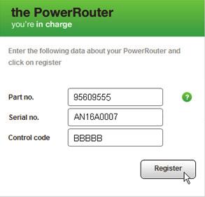
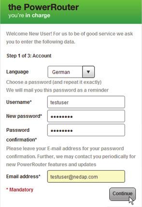
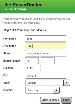
33 4 Installation PowerRouter Unifit Installation manual Connect to a wireless access point An example of a connection is shown in figure 16. The numbers in the drawing are: 1. Internet modem / router. 2. DSL, ISDN, or cable connection. 3. Power adapter for the internet modem / router. 4. Wireless access point. 5. CAT5e UTP cable (or better). 6. PowerRouter. The wireless access point must support wireless client function, and it must have a RJ45 connection. If in doubt consult your supplier. The PowerRouter cannot connect to the internet via a proxy server Register the PowerRouter on mypowerrouter.com 1. Make sure you have the Part.no., Serial no., and Control code available as mentioned on the type label of the PowerRouter (figure 1). 2. Check the internet connection via menu > service > status > internet connection. The display should show OK. 3. Go to a computer and open mypowerrouter.com. 4. In the login screen click New user (figure 20). 5. Fill out the Part.no., Serial no., Control code, and click Register (figure 21). 6. Fill out the fields in the window (figure 22), and click Continue. 7. Fill out the fields in the window (figure 23), and click Continue. 8. You will receive a confirmation Register additional PowerRouter systems to a single login You can register additional PowerRouter systems to a single login / user. To do this: 1. Login on mypowerrouter.com. 2. Click My PowerRouter. 3. Click New PowerRouter (figure 24). 4. Fill out the Part.no., Serial no., Control code, and click Register PowerRouter (figure 25). The PowerRouter internet connection will not work if a proxy server is being used. Do not use the AC local out of the PowerRouter to provide power to the internet router, or internet switch, the connection will be lost during a reset. 32
34 PowerRouter Unifit Installation manual 4 Installation i The PowerRouter only uses internet port 80. This is the default setting on most networks. The PowerRouter needs a DHCP server within the network. This should be provided by the internet router or the internet switch. To test the connection, connect a PC with a dynamic IP address to the connection that you will use for the PowerRouter. Open a web page. If the web page opens, the connection works. The maximum length of the CAT5e UTP cable (or better) is 20 meters. If you need to clear a longer distance, you can use an additional router or switch, and an additional cable of 20 meters. Power-line communication may result in an unreliable internet connection. 33
35 5 Installation Tool PowerRouter Unifit Installation manual 5 Installation Tool 5.1 Introduction After the initialisation with the PowerRouter Installation Tool it is possible to make advanced settings to further optimise the PowerRouter. Below you find an overview of features that are available in the installation tool, under advanced settings. Each feature has a short description, for detailed information refer to the help available in the installation tool or the guideline (download from The installation tool has a menu option re-install. If you use this wizard, default battery settings will be provided. Based on these settings the PowerRouter resets other battery settings overwriting any customized battery settings. Any customized battery settings will be lost. i You can download the latest version of the PowerRouter installation tool and guideline via the PowerRouter website. You need your login details for this website. You can request login details via Check the website regularly for updates to the PowerRouter installation tool. 5.2 Display settings Back-light Sets the time the PowerRouter's back-light stays on after pressing a button Display Select the information that will be shown by default in the display of the PowerRouter Language Select the language of the display of the PowerRouter. 34
36 PowerRouter Unifit Installation manual 5 Installation Tool 5.3 PowerRouter settings Self-use Within the limits of the battery it can be determined how far the battery is discharged. Support for backup can be turned on and off. During self-use the maximum compensation with battery power can be limited Winter mode Wintermode sets the time period in which it is not efficient to use the battery for self-use compensation Alarm 1 / Alarm 2 The PowerRouter is provided with 2 user-selectable relays referred as K201 and K202. This chapter describes the different alarms you may assign. After specifying the alarm it needs to be assigned to the relay icon, appearing next to the alarm icon in the installation tool. The relay icon can be selected after configuring the alarm. Off This is the default selection for an alarm relay. It is off or not used. Grid voltage alarm When the grid voltage is outside of the desired range the alarm relay is inactive. This can be used to switch on loads or sound an alarm when the grid voltage is out of range. For example to protect sensitive loads against high voltage. Or to switch on additional loads when the grid voltage is high. Which is usually an indication of high feed-in power. Battery State of Charge (SoC) Alarm based on the battery state of charge. The alarm relay is activated when the battery State of Charge is outside the specified range. Battery temperature alarm Alarm based on the temperature of the battery pack. The alarm relay is activated when the temperature of the battery pack is above the specified range. Battery voltage alarm Alarm based on the voltage of the battery pack. The alarm relay is activated when the battery voltage below the specified range. Grid connection alarm Alarm based on whether the system is connected to the grid. The relays are inactive if the system is in standby and no grid is available to power the relays. This alarm is not to be used for backup functionality. 35
37 5 Installation Tool PowerRouter Unifit Installation manual Energy management Switch on additional loads when a surplus of solar energy is available to increase the self-use. Self-use with backup Alarm based on whether the system is connected to the grid. When disconnected from the grid, the PowerRouter will switch to backup mode Standby Select that the PowerRouter can go in standby. The PowerRouter will go in to standby when there is no solar power or battery power available Standby timer Select a time interval, in which the PowerRouter goes to standby. 5.4 Grid Country Set the country grid settings for a specific country. It is not allowed to select a different country, than the country where the PowerRouter is installed Grid limits All grid limits can be changed in order to allow specific settings, which may be required by the utilities EEG 2012 Set the dedicated parameters to your installation size to comply with the German EEG 2012 regulation Reactive power control Set the reactive power curve in order to comply with the local utility requirements (only available for countries where this rule applies) Dynamic feed-in limiter With the dynamic feed-in limiter the output of the system can be adjusted. You can: Limit the output of the system. Limit the output to the grid after the point where the load is connected to the grid. 36
38 PowerRouter Unifit Installation manual 5 Installation Tool 5.5 Battery pack You can change: Product type Battery brand Battery type Incorrect settings may harm the batteries Battery discharging This option is not available for 48V Li-ion batteries. For 48V lead-acid batteries the cyclic DOD and the max. DOD can be set. Incorrect settings may harm the batteries Battery charging This option is not available for 48V Li-ion batteries. For 48V lead-acid batteries you can change: Charging method. Absorption and float charge Charge current. Incorrect settings may harm the batteries Maintenance charge This option is not available for 48V Li-ion batteries. For 48V lead-acid batteries you can set the interval of when to perform the maintenance charge. 37
39 6 Operation PowerRouter Unifit Installation manual 6 Operation 6.1 Display menu Open the menu Press any button on the display to open the menu. Navigate through the menu Use the UP/DOWN buttons to navigate through the menu. Use YES to open the selected item. Use NO to return to the previous item. Select and change settings Use YES to change a selected setting. Use the UP/DOWN buttons to change the selected setting. Use YES to confirm the changed setting. Use NO to cancel the change. Main menu Status menu History menu Settings menu Service menu System Grid Language Status Grid Battery Date & Time Revision Battery Display Reset Internet connection Error Install Wizard Maintenance charge Winter mode Selftest 38
40 PowerRouter Unifit Installation manual 7 Troubleshoot 7 Troubleshoot 7.1 Troubleshooting If you encounter difficulty with the operation of your PowerRouter, follow the steps below: Check the LED status. Check the error message on the LCD display, and the error history. If the difficulty remains, contact your installer / dealer. Collect the following information before you contact your installer or dealer (figure 1): Model number Serial number Brief description of the problem LED status Displayed error message Error history Software version and ID number 7.2 Check the LED status When an error has occurred the LEDs will either be OFF or FLASHING as follows: PowerRouter state Operational (blue) Charging (blue) Grid (blue) Error (red) Normal Operation on * * off Standby blinking off off off Not initialised blinking off off blinking System check off on * off Soft error on * * on Hard error off off off blinking Firmware update** off off * on Validating the grid * * blinking * Grid connected * * on * Fast charging batteries * blinking * * Charging batteries * on * * Using battery power * off * * * The LED can be on, blinking, or off. ** The PowerRouter is receiving / installing an update, this process may last for 25 minutes. The display will show a progress bar from 0% to 100%. During this time you must not do any other actions on the PowerRouter. 39
41 7 Troubleshoot PowerRouter Unifit Installation manual 7.3 Check the error messages The PowerRouter shows the latest error message on the display. The last ten error messages are stored in the error history. For possible solutions see section 7.5. Most errors are cleared automatically by the system if the error condition disappears. If an error message does not clear itself, press the NO button for at least 3 seconds to clear the error. 7.4 Error explanation Hard error When a hard error occurs the PowerRouter goes into a safe mode and will not function until the user has turned the system off and on or a reset is performed. A hard error is indicated when the error LED is flashing Soft error When a soft error occurs the module in which the error originated will go into a safe mode. Other modules in the PowerRouter will continue to operate. The PowerRouter can recover from the error automatically. A soft error is indicated when the error LED is on Error code Example: P027-H P The first letter indicates where the error originated within the PowerRouter P - Platform B - Battery module G - Grid module 027 The number indicates which error has occurred H The second letter indicates the level of the error that occurred H - Hard error S - Soft error 40
Installation Manual. PowerRouter Solar Battery self-use. Version
 Installation Manual PowerRouter Solar Battery self-use Version 011212 Standby Drill template the PowerRouter Standby Standby Drill template the PowerRouter Standby Standby Standby Standby Standby Standby
Accessories for Stand-alone inverter SUNNY ISLAND GENMAN
 Accessories for Stand-alone inverter SUNNY ISLAND GENMAN Technical Description GenMan-TEN082730 98-2001230 Version 3.0 EN SMA Solar Technology AG Table of Contents Table of Contents 1 Notes on this manual..............................
T Series (N6052T) Solar Battery Hybrid System. Installation Manual Version 1.1
 Solar Battery Hybrid System. Installation Manual Version 1.1") T Series (N6052T) Solar Battery Hybrid System Installation Manual Version 1.1 Content 1. Safety... 1 1.1 How to Use This Manual... 1 1.2 Safety Rules... 1 1.3 Warning Notices Affixed to the Device... 2
T Series (N6052T) Solar Battery Hybrid System Installation Manual Version 1.1 Content 1. Safety... 1 1.1 How to Use This Manual... 1 1.2 Safety Rules... 1 1.3 Warning Notices Affixed to the Device... 2
ENERGY MANAGER. Installation Manual
 ENERGY MANAGER Installation Manual Safety Information Manual for Maxem Home Energy Manager. Publication Date: November 1, 2016 Questions or improvements If you see any errors or defects, if you have ideas
Installation and Operating Instructions. MPPT Solar System Controller ISC3040
 Installation and Operating Instructions MPPT Solar System Controller ISC3040 ABOUT THIS MANUAL These operating instructions come with the product and should be kept with it as a reference to all user s
12/24 VOLT AUTOMATIC SOLAR CHARGE CONTROLLER
 12/24 VOLT AUTOMATIC SOLAR CHARGE CONTROLLER P/No.s SC320 & SC330 WARNING Please read these instructions completely prior to installation. Lead acid batteries can be dangerous. Ensure no sparks or flames
User Manual. Solar Charge Controller 3KW
 User Manual Solar Charge Controller 3KW 1 CONTENTS 1 ABOUT THIS MANUAL... 3 1.1 Purpose... 3 1.2 Scope... 3 1.3 SAFETY INSTRUCTIONS... 3 2 INTRODUCTION... 4 2.1 Features... 4 2.2 Product Overview... 5
GEatom306KHF-5U Three-phase Grid-Tied Battery Inverter. Version 1.1. Global Mainstream Dynamic Energy Technology Ltd. 1
 GEatom306KHF-5U Three-phase Grid-Tied Battery Inverter Version 1.1 Global Mainstream Dynamic Energy Technology Ltd. 1 Content Prelude... 4 1. Safety... 5 1.1 How to Use This Manual... 5 1.2 Safety Rules...
Installation and operating instructions. Solar charge controller 10 A / 15 A / 0 A / 30 A PHOTOVOLTAIK - PHOTOVOLTAICS - PHOTOVOLTAIQUE - FOTOVOLTAICA
 PHOTOVOLTAIK - PHOTOVOLTAICS - PHOTOVOLTAIQUE - FOTOVOLTAICA Installation and operating instructions Solar charge controller 10 A / 15 A / 0 A / 30 A EN 74.86 08.4 1. About this manual These operating
DC Master 24/ A
 USERS MANUAL DC Master 24/12 50-60A DC-DC converter MASTERVOLT Snijdersbergweg 93, 1105 AN Amsterdam The Netherlands Tel.: +31-20-3422100 Fax.: +31-20-6971006 www.mastervolt.com ENGLISH Copyright 2015
System Monitoring SCHOOLMETERBOX AU
 System Monitoring SCHOOLMETERBOX AU Installation Guide SMETER-IEN084710 98-00013210 Version 1.0 EN SMA Solar Technology AG Table of Contents Table of Contents 1 Notes on this Manual..............................
NEW SOLAR CHARGE CONTROLLERS
 190 SOLAR CHARGE CONTROLLERS Steca Solarix 2020-x2 Dual battery charge controller The Steca Solarix 2020-x2 is a state-of-the-art dual battery charge controller that is ideal for use in leisure applications.
Wind Power Inverter WINDY BOY 5000A/6000A
 Wind Power Inverter WINDY BOY 5000A/6000A User Manual WB5A-6A-BA-BEN114530 TBEN-WB50-60A Version 3.0 EN SMA Solar Technology AG Table of Contents Table of Contents 1 Information on this Manual.........................
Installation and operating instructions. Solar charge controller MPPT 10 A / 20 A Z Z
 Installation and operating instructions Solar charge controller MPPT 10 A / 20 A EN 1 Contents 1. About these instructions... 3 1.1 Applicability... 3 1.2 Users... 3 1.3 Description of symbols... 3 2.
PowerRouter Solar Battery Self-use
 PowerRouter Solar Battery Self-use the PowerRouter > Generate your own energy from solar energy > Store self-generated energy > Use stored energy > Save on energy costs > Monitoring and management via
SP PRO KACO Managed AC Coupling
 SP PRO KACO Managed AC Coupling Introduction The SP PRO KACO Managed AC Coupling provides a method of linking the KACO Powador xx00 and Powador xx02 series grid tie inverters to the SP PRO via the AC Load
My Reserve 500 Install Guide
 My Reserve 500 Install Guide System Overview Diagram Warnings Disclaimer of Liability and Warranty: This guide does not replace the Owner s Guide and Installation Instructions supplied with the components.
User Manual Solar Charge Controller 3KW
 User Manual Solar Charge Controller 3KW Version: 1.3 CONTENTS 1 ABOUT THIS MANUAL... 1 1.1 Purpose... 1 1.2 Scope... 1 1.3 SAFETY INSTRUCTIONS... 1 2 INTRODUCTION... 2 2.1 Features... 2 2.2 Product Overview...
Installing a Programmed Fronius SCERT in a Managed AC Coupled system
 Installing a Programmed Fronius SCERT in INTRODUCTION This document is included with Fronius SCERT PV Inverters that have been programmed. It applies only to units that have been programmed and are ready
Accessories for Wind Power Inverter WINDY BOY PROTECTION BOX 400 / 500 / 600
 Accessories for Wind Power Inverter WINDY BOY PROTECTION BOX 400 / 500 / 600 Installation Guide WBP-Box-IEN103320 IMEN-WBP-BOX Version 2.0 EN SMA Solar Technology AG Table of Contents Table of Contents
PV Inverter SUNNY MINI CENTRAL 9000TL / 10000TL / 11000TL with Reactive Power Control
 PV Inverter SUNNY MINI CENTRAL 9000TL / 10000TL / 11000TL with Reactive Power Control User Manual SMC9-11TLRP-BA-en-30 TBEN-SMCTLRP Version 3.0 EN SMA Solar Technology AG Table of Contents Table of Contents
Operating Manual MP-3739
 Operating Manual MP-3739 1 About this manual These operating instructions come with the product and should be kept for the life of the product for proper installation and usage. Read these operating instructions
Battery Charger. Series EASY Charger. User s manual
 Battery Charger Series EASY Charger User s manual 1 Warranty RIPEnergy is not manufacturer of these units. All technical information s, data s and dimensions rely on information s given by the manufacturer.
MAKING MODERN LIVING POSSIBLE. UniLynx Indoor Installation Manual. ULX 1800i ULX 3000i ULX 3600i ULX 5400i SOLAR INVERTERS
 MAKING MODERN LIVING POSSIBLE UniLynx Indoor Installation Manual ULX 1800i ULX 3000i ULX 3600i ULX 5400i SOLAR INVERTERS Contents Contents 1. Introduction 2 Introduction 2 Installation Sequence 2 Important
Installation and Operating Instructions. Solar System Controller ISC3030
 Installation and Operating Instructions Solar System Controller ISC3030 ABOUT THIS MANUAL These operating instructions come with the product and should be kept with it as a reference to all user s of the
Installation and Operating Instructions. Solar System Controller ISC3020
 Installation and Operating Instructions Solar System Controller ISC3020 ABOUT THIS MANUAL These operating instructions come with the product and should be kept with it as a reference to all user s of
CX-SERIES ADVANCED BATTERY CHARGER
 CX-SERIES ADVANCED BATTERY CHARGER Table of Content 1. IMPORTANT SAFETY INFORMATION... 2 1-1 General Safety Precautions... 2 1-2 Battery Precautions... 2 2. FEATURES... 3 2-1 Battery Charging Curve...
SNMP dedicated to ORVALDI Solar Infini
 SNMP dedicated to ORVALDI Solar Infini User s Manual Management Software for Solar Inverter Table of Contents 1. 2. 3. Overview...1 1.1 Introduction...1 1.2 Features...1 1.3 Overlook...1 1.4 Installation
Installation and operating instructions. Solar charge controller Solarix MPPT 1010 and Z Z
 Installation and operating instructions Solar charge controller Solarix MPPT 1010 and 2010 EN 730927 Z04 1440 730927 Z04 1440 1 Contents 1. About these instructions...3 1.1 Applicability...3 1.2 Users...3
Inverter / Charger Accessory for Steca Solarix PLI Phase / Parallel Kit. Installation and operating instructions Z01 17.
 Inverter / Charger Accessory for Steca Solarix PLI 5000-48 3-Phase / Parallel Kit Installation and operating instructions GB Z01 17.31 Table of Contents About this Manual... 2 Purpose... 2 Scope... 2 Keywords
3400W Solar Battery Charger Maximum Power Point Tracker
 Page 1 of 8 This revolutionary maximum power point tracker solar charger was designed using the technology that won GSL Electronics the prestigious EDN Innovation Awards 08 and 09 and the Greentech Consensus
Battery Charger Series EASY Charger
 Battery Charger Series EASY Charger User s manual 1 Warranty RIPEnergy is not manufacturer of these units. All technical information s, data s and dimensions rely on information s given by the manufacturer.
Manual. BlueSolar Grid Inverter 1500 / / / / / 230
 Manual EN BlueSolar Grid Inverter 1500 / 230 2000 / 230 2800 / 230 4000 / 230 5000 / 230 Before you start This manual contains important information regarding installation and safe operation of this unit.
Installation Guide B-BOX Pro2.5 ~ 10.0
 Installation Guide B-BOX Pro2.5 ~ 10.0 20170625 Version:2.1 1 / 37 Content Safety... 4 1 Product overview... 5 2 Cabinet terminal introduction... 6 3 Cable outlet of cabinet... 7 4 B-Plus2.5 interface
Sinewave Inverters. SWING 150VA and 300VA. User s manual
 Sinewave Inverters SWING 150VA and 300VA User s manual 1 Warranty RIPEnergy is not manufacturer of these units. All technical information s, data s and dimension s rely on information s given by the manufacturer.
PLUS PLUS & PRO. Installation manual
 PLUS PLUS & PRO Installation manual Safety warnings Manual for Maxem Plus and Pro Energy Manager. Publication Date: May 15, 2017 Questions or improvements If you see any errors or defects, if you have
Relay Retrofit Program Cutting Tool Safety Guide
 Relay Retrofit Program Cutting Tool Safety Guide Copyright This document and parts thereof must not be reproduced or copied without written permission from ABB, and the contents thereof must not be imparted
1700W Solar Battery Charger Maximum Power Point Tracker
 Page 1 of 8 This revolutionary maximum power point tracker solar charger was designed using the technology that won GSL Electronics the prestigious EDN Innovation Awards 08 and 09 and the Greentech Consensus
PSU EN54-4 Power Supplies
 PSU EN54-4 Power Supplies Ordering: Models, Sales Order Parts: PSU MXP-549 : 1.5A PSE in 7Ah enclosure MXP-550 : 3.0A PSE in 17/18Ah enclosure MXP-550D : 3.0A PSE in 25Ah enclosure MXP-551 : 5.0A PSE in
Getting started with
 PART NO. CMA113 MADE IN CHINA 1. Measuring CAT II 2. Max. voltage 250V ~ 3. Max. current 71 Amp Getting started with Electricity consumption & Solar PV generation monitoring single phase, for homes fitted
The Traveler Series TM : Adventurer
 The Traveler Series TM : Adventurer 30A PWM Flush Mount Charge Controller w/ LCD Display 2775 E. Philadelphia St., Ontario, CA 91761 1-800-330-8678 Version: 3.4 Important Safety Instructions Please save
Manual. EN Appendix. Lynx Ion BMS 400A / 1000A
 Manual EN Appendix Lynx Ion BMS 400A / 1000A 1. SAFETY INSTRUCTIONS 1.1 In general Please read the documentation supplied with this product first, so that you are familiar with the safety signs en directions
User Manual Rittal PMC UPS 6kVA
 User Manual Rittal PMC UPS 6kVA Germany Rittal GmbH & Co. KG Auf dem Stützelberg D-35745 Herborn Tel.: ++49-27 72-5 05-0 Fax: ++49-27 72-5 05-23 19 Internet: www.rittal.de 26 Contents 1. Introduction...
Power Meter INSTRUCTION MANUAL. Model Number: AESPP AUS
 Power Meter Model Number: AESPP-0718 INSTRUCTION MANUAL 1 Welcome Congratulations on choosing to buy a Bauhn product. All products brought to you by Bauhn are manufactured to the highest standards of performance
Owners Manual for TPMS plus GPS
 To ensure correct operation and service please read these instructions before installing and operating the TPMS feature of the TPMS/GPS unit. Owners Manual for TPMS plus GPS TABLE OF CONTENTS TIRE PRESSURE
B-RAD Select USER MANUAL TABLE OF CONTENTS
 TABLE OF CONTENTS TABLE OF CONTENTS... 1 MANUAL REVISION HISTORY... 2 IMPORTANT SAFETY NOTICE... 3 1.0 General Information... 5 1.1 System Components... 5 1.2 Specifications... 5 1.2.1 Torque Ranges...
Eclipse Solar Suitcase
 Eclipse Solar Suitcase Renogy 100W 200W 2775 E. Philadelphia St., Ontario, CA 91761 1-800-330-8678 Version 1.0 Important Safety Instructions Please save these instructions. This manual contains important
MB A 12V/24V DC PROGRAMMABLE DUAL BATTERY ISOLATOR
 MB-3688 120A 12V/24V DC PROGRAMMABLE DUAL BATTERY ISOLATOR User Manual Warning and Precautions MB-3688 is built with corrosion resistant material and the main electronic assembly is well sealed inside
Solar System Controller
 POWER FAULT 50 Amp MPPT Installation and Operating Instructions Solar System Controller ISC5040 ABOUT THIS MANUAL These operating instructions come with the product and should be kept with it as a reference
The Traveler Series: Adventurer
 The Traveler Series: Adventurer RENOGY 30A Flush Mount Charge Controller Manual 2775 E. Philadelphia St., Ontario, CA 91761 1-800-330-8678 Version: 2.2 Important Safety Instructions Please save these instructions.
Installation and Programming Manual Part: Building Network Interface Card Product: 4100ES
 Installation and Programming Manual Part: Building Network Interface Card 4100-6047 Product: 4100ES Cautions and Warnings READ AND SAVE THESE INSTRUCTIONS- Follow the instructions in this installation
10A / 15A / 20A Solar Charge Controller. PU1024 / PU1524 / PU2024 series INSTRUCTION MANUAL
 10A / 15A / 20A Solar Charge Controller PU1024 / PU1524 / PU2024 series INSTRUCTION MANUAL Dear Customer, Thank you very much for choosing our product. This manual contains important information about
Sinewave Inverters. SWING pro 200VA and 350VA. User s manual
 Sinewave Inverters SWING pro 200VA and 350VA User s manual 1 Warranty RIPEnergy is not manufacturer of these units. All technical information s, data s and dimension s rely on information s given by the
Pure Sine Wave Inverter 600W-24V User Manual
 Pure Sine Wave Inverter 600W-24V User Manual Manual Version:INV-600W-2016-1 Table of Contents 1. INTRODUCTION... 1 1.1 General Description... 1 1.2 Key Features... 2 2. SAFETY INSTRUCTIONS... 2 2.1 Installation
PV inverter SUNNY MINI CENTRAL 7000HV
 PV inverter SUNNY MINI CENTRAL 7000HV User Manual SMC70HV11-BA-BEN112930 TBEN-SMC70HV Version 3.0 EN SMA Solar Technology AG Table of Contents Table of Contents 1 Information on this Manual.........................
User s Manual. Automatic Switch-Mode Battery Charger
 User s Manual Automatic Switch-Mode Battery Charger IMPORTANT Read, understand, and follow these safety rules and operating instructions before using this battery charger. Only authorized and trained service
User Manual 1KVA/ 2KVA/ 3KVA INVERTER / CHARGER
 User Manual 1KVA/ 2KVA/ 3KVA INVERTER / CHARGER CONTENTS ABOUT THIS MANUAL... 1 Purpose... 1 Scope... 1 SAFETY INSTRUCTIONS... 1 INTRODUCTION... 2 Features... 2 Basic System Architecture... 2 Product Overview...
Eclipse series Solar Inverter Installation Manual
 Eclipse series Solar Installation Manual Applicable Models This manual covers the following MIL-Solar inverter base models: Eclipse 3000-II Eclipse 4000-II Eclipse 4600-II Eclipse 4950-II Eclipse 5000-II
Combined Ventilation Controller RVWS-T-224HA
 Combined Ventilation Controller RVWS-T-224HA 8-stage Control for Power/Natural Applications 2 variable speed stages, 2 curtain winch stages, 2 fixed speed ventilation stages, 1 thermo/mister cycle stage
80V 300Ah Lithium-ion Battery Pack Data Sheet
 80V 300Ah Lithium-ion Battery Pack Data Sheet 80 V, 300 amp-hour capacity, maintenance-free energy storage, IP65 design, fully integrated BMS, integrated fuse and safety relay protection, highly configurable
Sinewave Inverters. Jazz 700VA and 1000VA. User s manual
 Sinewave Inverters Jazz 700VA and 1000VA User s manual 1 Warranty RIPEnergy is not manufacturer of these units. All technical information s, data s and dimension s rely on information s given by the manufacturer.
User manual. Solar Hybrid 1-5KVA. Uninterruptible Power Supply / Charger
 User manual Solar Hybrid 1-5KVA Uninterruptible Power Supply / Charger All rights reserved. The information in this document is subject to change without notice. Thank you for purchasing this series UPS.
BATTERY METER SMART BATTERY GUAGE
 BATTERY METER SMART BATTERY GUAGE P/No. BM320 IMPORTANT SAFETY INFORMATION Please read this instruction thoroughly before installing the product. WARNINGS Risk of explosive gas. Working in the vicinity
CPS Energy Balancer. Version: 1.0
 CPS Energy Balancer Version: 1.0 CHINT POWER SYSTEMS AMERICA CO., LTD. Address: 700 International Parkway, Suite 102 Richardson, Texas Zip Code: 75081 Web: www.chintpower.com/na Email: americasales@chintpower.com
CLA-VAL e-drive-34. User Manual. Motorised Pilots. CLA-VAL Europe LIN072UE - 04/16
 User Manual CLA-VAL Europe www.cla-val.ch cla-val@cla-val.ch 1 - LIN072UE - 04/16 Table of Contents 1 Introduction... 3 1.1 Precautions Before Starting... 3 1.2 Troubleshooting... 3 1.3 General Disclaimer...
SI AT A22. English. Printed: Doc-Nr: PUB / / 000 / 03
 SI AT A22 English 1 Information about the documentation 1.1 About this documentation Read this documentation before initial operation or use. This is a prerequisite for safe, trouble-free handling and
PF3100 TROUBLESHOOTING SOLUTIONS TO COMMON PROBLEMS. v1.1 Revised Nov 29, 2016
 PF3100 TROUBLESHOOTING SOLUTIONS TO COMMON PROBLEMS v1.1 Revised Table of Contents 1 Common Alarms and Warnings... 1 2 Common Issues... 6 2.1 Communication problems... 6 2.1.1 Controller communication
Operation Manual Pika Islanding Inverter X7602/X Part of the Pika Energy Island M
 Operation Manual Pika Islanding Inverter X7602/X11402 Part of the Pika Energy Island M00010-17 Islanding Inverter Serial Number: RCP Number: We are committed to quality and constant improvement. All specifications
icon Solar Battery Charge Controller for Home UPS
 icon Solar Battery Charge Controller for Home UPS 1. Introduction icon is an intelligent solar charge controller that is capable of converting the existing home battery backup systems like inverters and
C3 Operating Instructions
 Version 3.1 Stand 09.2014 Robert Bosch (Australia) Pty. Ltd. 1555 Centre Road Clayton, Victoria 3168 C3 Operating Instructions For further information please contact Bosch at: Australia 1300 30 70 40 www.boschautoparts.com.au
SimpliPhi Power PHI Battery
 Power. On Your Terms. SimpliPhi Power PHI Battery INTEGRATION GUIDE: VICTRON Optimized Energy Storage & Management for Residential & Commercial Applications Utilizing Efficient, Safe, Non-Toxic, Energy
/ Optimised energy management. / Dynamic Peak Manager. / Smart Grid Ready 12.0 A / 12.0 A 18.0 A / 18.0 A
 / Perfect Welding / Solar Energy / Perfect Charging FRONIUS PRIMO / Optimised energy management. N W E S / SnapINverter Technology / Integrated data communication / SuperFlex Design / Dynamic Peak Manager
Operating instructions
 Operating instructions Digital tank contents indicator DTA 10 DTA 10 DTA 10 0 4.0 m fuel oil 0 3.5 m water Read instructions before using device! Observe all safety information! Keep instructions for future
HP Series Smart Solar Charge Controller HP2430/2440/2450/2460 HP4830/4840 UserManual
 HP Series Smart Solar Charge Controller HP2430/2440/2450/2460 HP4830/4840 UserManual Dear users Thank you for choosing our product. Before using the product, please read this manual carefully.productfeatur
UGE-4K Off-Grid Controller OWNER S MANUAL
 UGE-4K Off-Grid Controller OWNER S MANUAL CONTENTS INTRODUCTION... 3 PARTS LIST... 4 SPECIFICATIONS... 5 SAFETY INSTRUCTIONS... 6-7 INSTALLATION... 8 MOUNTING GUIDE... 9 WIRING DIAGRAM... 10 CONTROLLER
TRANSPONDER TERMINAL MANUAL. Version: July 2012
 Version: July 2012 2 1.0 PRODUCT DESCRIPTION 3 1.1 ORDER CODE 3 1.2 DESCRIPTION 3 2.0 WARNING 4 2.1 SAFETY 4 3.0 INSTALLATION 5 3.1 IMPORTANT 5 3.2 DIAGRAM 6 3.3 INSTALLATION PROCEDURE 7 4.0 CONNECTIONS
Battery charger , A, B
 Battery charger 420.093.050, 420.093.050.A, 420.093.050.B Battery charger 420.093.050, 420.093.050.A, 420.093.050.B englisch 12.09 2009 AUDI AG AUDI AG works continuously to develop and further improve
PWM Charge Controller with LCD Display 30A. User Manual
 PWM Charge Controller with LCD Display 30A User Manual 1 Product Features 1. 12V/ 24 V system voltages are automatically recognized. 2. Charging program options for sealed, GEL and flooded lead-acid batteries
TECHNICAL MANUAL. Inverter / Charger Combi. Combi SW 12V 1600VA Réf : PF Combi SW 24V 3800VA Réf : PF NOT_COMBI_SW-00
 TECHNICAL MANUAL EN Inverter / Charger Combi Combi SW 12V 1600VA Réf : PF.16088 Combi SW 24V 3800VA Réf : PF.16089 SAFETY PRECAUTIONS TO PREVENT ANY RISK OF ELECTRIC SHOCK OR FIRE, READ THIS MANUAL CAREFULLY
The Ultimate Smart Grid Solution INSTRUCTION MANUAL
 ECOWISE EW30/1 The Ultimate Smart Grid Solution INSTRUCTION MANUAL Welcome! Congratulations on selecting the ECOWISE unit to manage your energy supply needs. ECOWISE units reduce the amount of electric
Compact System NRGS 11-2 NRGS Original Installation Instructions English
 Compact System NRGS 11-2 NRGS 16-2 EN English Original Installation Instructions 810366-05 1 Contents Important Notes Page Usage for the intended purpose...4 Safety note...4 LV (Low Voltage) Directive
User Manual. Digital Energy Uninterruptible Power Supply ML Series UPS VA. GE Digital Energy Power Quality. GE imagination at work
 GE Digital Energy Power Quality User Manual Digital Energy Uninterruptible Power Supply ML Series UPS 350-500-700-1000 VA GE Consumer & Industrial SA General Electric Company CH 6595 Riazzino (Locarno)
Dycon D1532SM. EN50131/PD6662 Grade 3, 12V 2A Power Supply. Technical Description Installation and Operating Manual DYCON POWER SOLUTIONS LTD
 Dycon D1532SM EN50131/PD6662 Grade 3, 12V 2A Power Supply Technical Description Installation and Operating Manual DYCON POWER SOLUTIONS LTD Tel: +44 (0)1443 471 900 Unit A Cwm Cynon Business Park Mountain
Accessories for power generation plants in Italy SMA GRID GATE
 Accessories for power generation plants in Italy SMA GRID GATE Installation Manual GridGate-11-IA-en-12 Version 1.2 EN SMA Solar Technology AG Table of Contents Table of Contents 1 Information on this
User Manual Digital Energy Uninterruptible Power Supply ML Series UPS VA GE Digital Energy Power Quality
 GE Digital Energy Power Quality User Manual Digital Energy Uninterruptible Power Supply ML Series UPS 350-500-700-1000 VA GE imagination at work GB User Manual Digital Energy Uninterruptible Power Supply
KeContact P20. User manual
 KeContact P20 User manual Comments to this manual In this manual you will find warnings against possible dangerous situations. The used symbols apply to the following meanings:!! WARNING! Indicates a potentially
ALIEM USER MANUAL R. Bocconi. REV. DATE Checked and Approved R. T.
 ALIEM USER MANUAL 2 19-04-2018 R. Bocconi REV. DATE Checked and Approved R. T. PAGE INTENTIONALLY LEFT BLANK 2 ALIEM 1000 USER'S MANUAL Version 2 dated 19-04-2018 1 INTRODUCTION ALIEM 1000 is an emergency
Automatic Genset Controller, AGC-4 Display readings Push-button functions Alarm handling Log list
 OPERATOR'S MANUAL Automatic Genset Controller, AGC-4 Display readings Push-button functions handling Log list DEIF A/S Frisenborgvej 33 DK-7800 Skive Tel.: +45 9614 9614 Fax: +45 9614 9615 info@deif.com
SK-10. Features. Solar Charge Controller User Manual. Important Safety Information
 SK-10 Solar Charge Controller User Manual 12V/24V 10Amp Dear Users: Thank you for selecting our product. Please read this manual carefully before you use this product. This product is of cutting edge design,
3500W Solar Battery Charger Maximum Power Point Tracker
 Page 1 of 8 This revolutionary maximum power point tracker solar charger was designed using the technology that won GSL Electronics the prestigious EDN Innovation Awards 08 and 09 and the Greentech Consensus
Matson Programmable Voltage Sensitive Relay MA98411
 Matson Programmable Voltage Sensitive Relay MA98411 Matson Programmable Voltage Sensitive Relay The MPVSR is a solid state electronic relay which is activated by sensing the voltage of the circuits it
FLÄKTGROUP PM-MOTOR WITH INTEGRATED FC 106 FREQUENCY CONVERTER
 FLÄKTGROUP PM-MOTOR WITH INTEGRATED FC 106 FREQUENCY CONVERTER INSTALLATION AND MAINTENANCE INSTRUCTIONS Risk of electric shock: Motor terminals may still be live if the impeller is rotating, even when
DALI 650mA LED Driver
 Installation Guide DGLC650C18DD PATENT PENDING REGISTERED DESIGN Designed in Australia to meet Australian Standards and installation conditions DIGINET.NET.AU Diginet Control Systems Pty Ltd ABN 89 095
User Manual. NetGuard IMPORTANT. PSD 650/1200/1600 Line Interactive UPS Uninterruptible Power Supply System. UPS Monitoring Software
 User Manual Thank you for purchasing the Defender 650/1200/1600. It is designed to provide safe and reliable power protection to your precious electronics equipment. Before you start using the product,
Operating instructions. sonnenprotect for operators. KD-337 Part no Version X00.
 Operating instructions for operators sonnenprotect 1300 KD-337 Part no. 22010 Version X00 info@sonnenbatterie.de www.sonnenbatterie.de EN IMPORTANT Read this documentation carefully before operation. Retain
3400W Solar Battery Charger Maximum Power Point Tracker
 Page 1 of 8 A simple, compact low cost MPPT to efficiently charge lead acid and lithium iron batteries from a wide range of photovoltaic panels. The MPPT 60-2 is designed to charge lead acid and lithium
Your new LM controller is a state-of-the art device which was developed in accordance with the latest
 CAP LM-series Solar charge controller User Manual Thank you very much for buying this CAP product. Please read the instructions carefully and thoroughly before using the products. Your new LM controller
BYD Battery-Box LV Installation Guidance
 Battery-Box L 3.5/7.0/10.5/14.0 Version1.0 1 / 33 Contents 1 SAFETY... 6 2 PRODUCT OVERVIEW... 7 3 BCU INTRODUCTION... 7 4 DESCRIPTION OF B-PLUS L 3.5 INTERFACE AND TERMINAL... 8 5 PREPARATION... 9 5.1
Installation Guide Smart-UPS On-Line SRT1000/1500 UXI-NCLI, SRT1000/1500 UXI-LI, Tower/Rack-Mount
 Installation Guide Smart-UPS On-Line SRT1000/1500 UXI-NCLI, SRT1000/1500 UXI-LI, Tower/Rack-Mount Important Safety Messages Read the instructions carefully to become familiar with the equipment before
User Manual 1.5KVA-3KVA INVERTER / CHARGER. Version: 1.1
 User Manual 1.5KVA-3KVA INVERTER / CHARGER Version: 1.1 Table Of Contents ABOUT THIS MANUAL... 1 Purpose... 1 Scope... 1 SAFETY INSTRUCTIONS... 1 INTRODUCTION... 2 Features... 2 Basic System Architecture...