CATALOGUE MARINE APPLICATIONS. Energy performance solutions
|
|
|
- Arline Farmer
- 5 years ago
- Views:
Transcription


1 CATALOGUE MARINE APPLICATIONS Energy performance solutions


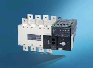
2 Marine Certifications Our certified products As an independent manufacturer, we, at Socomec are committed to adapting the range and certifications of our products according to our customer s needs. Thanks to our innovative technology, reliability and high performance levels, we are able to meet our customer s expectations and comply with the strict standards set by the world s top marine application certification bodies such as: BUREAU VERITAS Expert certification bodies such as Bureau Veritas, with international outreach regarding ship classifications, help us achieve the maritime safety levels you require, thus providing, benefits to ship-owners, shipbuilders, shipyards, equipment manufacturers, insurers, brokers, bankers and Flag States. Lloyd s Register is a leading international provider of consultancy services regarding classification and compliance with standards in the marine industry. Its goal is to assist in the design, construction and operation of products at the highest levels of safety and performance. Certified by Bureau Vertitas Certified by Lloyd s Certified by Rina SIRCO Load break switches from 125 to 5000 A p. 10 SIRCOVER Manually operated TSE from 125 to 3000 A p. 66 ATyS Automatic TSE from 125 to 3200 A p. 82 FUSERBLOC Fusible disconnect switches from 32 to 400 A p. 32 FUSERBLOC Fusible disconnect switches from 32 to 400 A p. 32 BUREAU VERITAS Rina Services S.p.A is the operational branch of RINA, providing services in ship classification, certification, verification of conformity, inspection and testing. Rina can offer its experience and commitment to companies operating in various markets, and seeking to reach the highest levels of quality, efficiency, safety and sustainability. Certified by DNV GL RM and RMS Fuse holder from 32 to 100 A p. 62 DNV GL is the world s largest classification body with 13,175 vessels and mobile offshore units (MOUs) amounting to million gt in its portfolio. DNV GL is also a reference in the renewable, alternative and conventional energy sectors. It is the world s largest technical consultancy for the onshore and offshore wind, wave, tidal and solar industries. NETYS RT-M UPS solution for marine application p. 128 The complete list of certified references Find the complete list of certified references page 130.

3

4 Contents An independent manufacturer... Four key applications: know-how of a specialist... Expert Services your partner... A cutting-edge laboratory... p. 6 p. 7 p. 8 p. 9 Certified references... p. 130 Load break switches Our certified products SIRCO 125 to 3200 A p. 10 BUREAU VERITAS Fuse protection Fuse disconnect switches Fuse holder FUSERBLOC 25 to 1250 A p. 32 RM - RMS 32 to 125 A p. 62 Find the complete list of certi ed references p. 130 Transfer switches Manual transfer switches Motorised transfer switches SIRCOVER 125 to 3200 A p. 66 ATyS 125 to 3200 A p. 82 Enclosure & accessories Busbar supports p. 106 Single-phase UPS NETYS RT-M 1100 and 3300 VA p. 128 Catalogue


5 Your requirements The International Maritime Organisation has put a strong emphasis on the following three major challenges: security, safety and efficiency. This is reflected in their official slogan: Safe, secure and efficient shipping on clean oceans. To meet these challenges, the marine industry requires reliable equipment, able to supply power to applications operating in harsh environments. Socomec s marine product range has taken this into consideration by offering products tested and certified to meet these requirements. Whether you are seeking to secure the safety of your offshore building, cargo or private vessels, we have created certified products to meet your requirements. 4 Catalogue


. Offer high performance products which also require the least amount of down time.(mttr).")
6 Our commitment Quality Ensure operations of the equipment in conditions specific to marine environments Offer products capable of withstanding high levels of vibration and harsh environments. Offer products which exceed requirements for marine norms and certification. Security Assure the safety of people and infrastructure Protect the passengers and personnel on board of cargo, passenger ships and private vessels. Protect permanent and temporary offshore installations. Protect critical equipment for the navigation system, communication and engine controls against power outages. Reliability Assure the maximum availability of the installation Offer reliable products specially designed with the least amount of separate parts and breaking points in order to maximize service lifetime (MTBF). Offer high performance products which also require the least amount of down time.(mttr). Service Facilitate the use of our products Assist the design and application of solutions. Offer support wherever you are, thanks to our worldwide network of service professionals. Answer all your questions, with our highly trained and qualified technical. Catalogue

7 An independent manufacturer The benefit of a specialist 3,500 m 2 of test platforms One of the leading independent power testing labs in Europe innovative! 65,000 on-site interventions per year Nearly 400 experts in commissioning, technical audit, consultancy and maintenance Since its foundation more than 0 years ago SOCOMEC continues to design and manufacture its core products in Europe otably solutions for its primary mission the a ailability control and safety of low oltage electrical networks As an independent manufacturer the Group is committed to constant inno ation to impro e the energy performance of electrical installations in infrastructures as well as industrial and commercial sites 10 % of turnover invested in Always at the cutting-edge of technology for innovative, high-quality products Throughout its history SOCOMEC has constantly anticipated market changes by de eloping cutting-edge technologies pro iding solutions that are adapted to customer requirements and fully in keeping with international standards Optimising the performance of your system throughout its life cycle - this is the commitment carried out e ery day by the SOCOMEC teams around the world where er your business is located SYDIV 181 B MADE IN EUROPE 6 Catalogue


8 Your energy, our expertise Critical Power Ensuring the availability and storage of high quality power With its wide range of continuously evolving products, solutions and services, Socomec are recognised experts in the cutting-edge technologies used for ensuring the highest availability of the electrical power supply to critical facilities and buildings, including: static uninterruptible power supplies (UPS) for high-quality power free of distortions and interruptions occurring on the primary power supply, changeover of static, high availability sources for transferring the supply to an operational back-up source, permanent monitoring of the electrical facilities to prevent failures and reduce operating losses, energy storage for ensuring the proper energy mix of buildings and for stabilisation of the power grid Datadock Power Control & Safety Managing power and protecting persons and facilities Active in the industrial switching market since its foundation in 1922, Socomec is today an undisputed leader in the field of low voltage switchgear, providing expert solutions that ensure: isolation and on load breaking for the most demanding switching applications, continuity of the power supply to electrical facilities via manual remotely operated or automatic transfer switching equipment protection of persons and assets via fusebased and other specialist solutions APPLI 575A Energy Efficiency Managing the energy performance of buildings Socomec solutions, from current sensors through to a wide choice of innovative scalable software packages are driven by experts in energy performance They meet the critical requirements of facility managers and operators of commercial, industrial and local authority buildings for: measuring energy consumption, identifying sources of excess consumption and raising the awareness of occupants about their impact, limiting reactive energy and avoiding the associated tariff penalties, using the best available tariffs, checking utility bills and accurately distributing energy billing among consumer entities, monitoring and detecting insulation faults APPLI 571A Expert Services Enabling available, safe Socomec is committed to delivering a wide range of value-added services to ensure the reliability and optimisation of end-users equipment: prevention and service operations to lower the risks and enhance the efficiency of operations, measurement and analysis of a wide range of electrical parameters leading to recommendations for improving the site s power quality, optimisation of the total cost of ownership and support for a safe transition when migrating from an old to a new generation of equipment consultancy, deployment and training from the project engineering stage through to final procurement APPLI 760A Catalogue


.")
.")
9 Expert Services your partner enabling available, safe and efficient energy SOCOMEC is committed to deliver a wide range of valueadded services to ensure the availability of your critical installation, the safety of your site operations and the performance optimisation of your low voltage equipment during its life cycle. The expertise and proximity of our specialists are there to ensure the reliability and durability of your equipment. APPLI 724 A Key figures Nearly 400 Socomec experts supported by 200 engineers and technicians from our distributors, drive the solutions to your specific needs. Our global presence includes: 10 branches in France, 12 European subsidiaries, 8 Asian subsidiaries, representatives in 70+ countries. Subsidiaries Distributors Contact us CARTE 063 H On-site service management 65,000 service operations per year (mainly preventive visits). 98% Service Level Agreement compliance rate. Technical hotline network 20+ languages spoken. 3 advanced technical support centres. 100,000+ incoming calls handled per year. Certified expertise 5,000 hours of technical training deployed per year (product, methodology and safety). APPLI 571 A SITE 588 A CORPO 269 A 8 Catalogue

10 A cutting-edge laboratory the backing of an expert Created in 1965, SOCOMEC s laboratory brings its expertise to guarantee the reliability and the conformity of our products and solutions. Since 2015, the laboratory renamed Tesla Lab Power Testing and Certification in 2015, offers its testing and certification services to all its customers. CORPO 441 A Proven expertise Tesla Lab is an independant laboratory specialised in testing of LV switchgears, components and switchgear assemblies. 4 M has been invested since 2011 in this 2000 m² laboratory, where 30 experts guarantee the quality of the performed tests, making the Tesla Lab one of the most modern laboratories in Europe. Vast range of tests The laboratory has 100 MVA (I cc 100 ka rms 1 s) short-circuit platform, three 10 ka overload platforms and many other test facilities covering 2000 m² for: functional tests, mechanical tests: endurance, dielectric tests, environmental tests: vibrations, Ingress Protection (IP), temperature rise tests up to 60 C ambient. International partnership The laboratory is recognised by the major certification bodies worldwide: member of ASEFA and LOVAG, it is accredited by COFRAC, UL (CTDP), CSA (shared certification) and DE RA (WMT). The partnership with many international certification bodies guarantees the quality and safety requirements in each country. Implementation of standard IEC / EN Electrical switchgear manufacturers IEC EN standards define the requirements of Low voltage switchgear assemblies as well as the tests necessary to ensure the achievement of the specified levels of performance. The compliance with these standards gives a guarantee of safety and performance to the user of the equipment An original manufacturer according to IEC / EN standards Socomec offers a wide range of original manufacturer solutions complying with IEC standards. FLEXYS and CADRYS cabinet systems designed for distribution panel applications. Local switching and equipment cabinets covering requirements in power availability and safety. Components for integration. Tesla Lab accredited by COFRAC With its world-class testing facilities, the Tesla Lab can perform all of the tests required by IEC EN standards for switchgear assemblies We can therefore help you to: define a verification program, perform conformity tests, issue test reports in order to get certification from third party certification bodies (ASEFA, LOVAG, DE RA, UL, CSA, COFRAC, ASTA ). Catalogue


. High resistance to damp heat (supplied \"tropicalised\").")


11 SIRCO Load break switches for power distribution from 125 to 5000 A The solution for Load break switches sirco-ac_001_a_1_cat sirco_456_a_1_cat SIRCO 3 x 250 A direct operation > Main switchboard > Distribution panel > Emergency breaking > Network coupling > Local safety breaking Function SIRCO and SIRCO AC are manually or remotely operated multipolar load break switches. They make and break under load conditions and provide safe isolation. SIRCO are designed for 415 VAC and DC low voltage electrical circuits. SIRCO AC are designed for heavy duty applications up to 690 VAC - AC 23. General characteristics SIRCO AC 3 x 250 A direct handle Double positive break indication given through a position indication window, located directly on the product, and by the operating handle. Severe load duty categories (AC-22 and AC-23). High resistance to damp heat (supplied "tropicalised"). Strong points > Reliability and performance > Safety of property and personnel > Simplicity > Easy to install Compliance with standards > IEC Approvals and certifications (1) Advantages Reliability and performance The double breaking per pole, achieved through its sliding bar contact system, is a proven design that offers very high durability and short-circuit withstand. Improved breaking performance with quick opening and rapid closure. Safety of property and personnel The position indicator is located directly on the sliding bar contact mechanism, ensuring it can be seen in all circumstances. The use of glass fibre reinforced polyester gives the SIRCO and SIRCO AC both high mechanical and thermal resistance. Simplicity The standardisation of the SIRCO and SIRCO AC range and its wide choice of common accessories enable: Simple mounting. Reduced stock management and storage costs. Easy to install The outdoors ranges are easy to install thanks to: A good centre-to-centre distance (up to 120 mm). Connection up to 6 x 185 mm². Connection accessories which facilitate both flat and edgewise connections. BUREAU VERITAS (1) Product reference on request. Enclosures > The S R and S R A range can be easily fitted in our enclosures and cabinets designed for electrical distribution. 10 Catalogue


12 SIRCO Load break switches for power distribution from 12 to 000 A What you need to know In front direct or external operation, SIRCO is available in 3 and 4-pole versions from 125 to 5000 A. It can be ordered in 6 or 8-pole versions from 125 to 1600 A. SIRCO is available in a polyester or sheet metal enclosure from 125 to 1250 A. sirco_372_b_1_cat For ratings 2000, 2500 and 3200A, a copper bar connection kit enables the connection between the two power terminals of one pole. Flat connection top or bottom Edgewise connection top or bottom acces_220_c_2_cat acces_223_b_2_cat Catalogue
13 SIRCO Load break switches for power distribution from 12 to 000 A SIRCO - References Standard applications - Front operation pole Rating (A) / Frame size No. of poles Switch body (1) Direct handle External handle 125 A / B3 160 A / B3 200 A / B4 250 A / B4 315 A / B5 400 A / B5 500 A / B5 630 A / B5 800 A / B A / B6 CD 1250 A / B A / B A / B A / B A / B A / B A / B A / B A / B B1 type Black (2) Red (1) Device available enclosed.(see "Enclosed load break switches" (2) Standard. (3) Top or bottom. B2 type Black (2) Red C2 type Black (2) Red V0 type Black (2) S2 type Black IP (2) Black IP Red IP Type S4 Black IP (2) Red IP V2 type Black IP (2) Red IP V0 type Black IP (2) Shaft for external handle 200 mm mm (2) 500 mm mm mm (2) 400 mm mm mm (2) 450 mm 2799 Auxiliary contact Terminal shrouds Terminal screens 1 st NO/NC contact nd NO/NC contact st /2 nd NO/NC contact included (3) (3) (3) (3) (3) (3) (3) (3) (3) (3) (3) (3) (3) (3) (3) (3) (3) (3) - 12 Catalogue
14 SIRCO Load break switches for power distribution from 12 to 000 A SIRCO AC - References eavy duty applications - Front operation 3 4 pole Rating (A) / Frame size No. of poles Switch body Direct handle External handle 200 A / B4 250 A / B4 315 A / B4 400 A / B5 500 A / B5 CD 630 A / B5 630 A / B6 800 A / B A / B6 CD A / B A / B A / B7 26AC AC AC AC AC AC AC AC AC AC AC AC AC AC AC AC AC AC AC AC AC AC AC AC 4160 J1 type Black (1) J1 type Red J4 type Black (1) Red S2 type Black IP (1) Black IP Red IP S4 type Black IP (1) Red IP Shaft for external handle 200 mm mm (1) 500 mm mm mm (1) 400 mm Auxiliary contact Terminal shrouds Terminal screens 1 st contact NO/NC nd contact NO/NC P (2)(3) (2)(3) 3P (2)(3) (2)(3) 3P (3) (3) 3P (3) (3) (2)(3) (2)(3) (2)(3) (2)(3) 2000 A / B A / B9 26AC AC 4200 S5 type Black (1) Red AC 3400 V0 type Black 26AC (1) S5 type Black IP (1) 200 mm Red IP mm (1) 450 mm V0 type Black 1st / 2nd (1) included (2)(3) (2)(3) 3/4P (4) (1) Standard. (2) Mandatory for voltage greater than 415 VAC. (3) Top or bottom. (4) Top and bottom. Catalogue
15 SIRCO Load break switches for power distribution from 12 to 000 A SIRCO - References Standard applications - Front operation pole Rating (A) / Frame size No. of poles Switch body Direct handle External handle Shaft for external handle Auxiliary contact Terminal shrouds Terminal screens 6 P P A / B3 DS 6 P P Type B3 Black (1) S2 type Black IP (1) Red IP mm mm (1) 6 P (2)(3) 8 P (2)(3) 6 P (4) 8 P (4) 6 P P P (2)(3) 8 P (2)(3) 6 P (4) 8 P (4) 6 P P A / B5 DS 6 P P Type C1 Black (1) Red Type S4 Black IP (1) Red IP mm mm (1) 1 st NO/NC contact nd NO/NC contact P (2)(3) 8 P (2)(3) 6 P (4) 8 P (4) 800 A / B6 DS 6 P P P P A / B7 DS 6 P P C2 type Black (1) Red Type V1 Black IP (1) 320 mm (1) - 6 P (4) 8 P (4) 1600 A / B7 DS (4) 6 P P 8 P (1) Standard. (2) Top or bottom on the front or rear of the device. (3) Select 2 sets for front or rear. (4) Top or bottom at the front of the device. 8 P (4) 14 Catalogue
16 SIRCO Load break switches for power distribution from 12 to 000 A Accessories Direct operation handle SIRCO direct operation handle Rating (A) / Frame size No. of poles Handle type Handle colour Reference / B3 3/ B1 Black (1) / B3 3/ B1 Red / B3 DS 6/8 P B3 Black (1) / B4-B5 3/ B2 Black (1) / B4-B5 3/ B2 Red / B4 DS -B5 DS 6/8 P C1 Black (1) / B4 DS -B5 DS 6/8 P C1 Red / B6...B8 3/ C2 Black (1) / B6...B8 3/ C2 Red / B6 DS -B7 DS 6/8 P C2 Black (1) / B6 DS -B7 DS 6/8 P C2 Red / B9 3/ V0 Black (1) (1) Standard. J1 type handle access_355_a B2 type handle acces_114_a_2_cat C2 type handle acces_153_a_2_cat S5 type handle acces_286_a_2_cat SIRCO AC direct operation handle Rating (A) / Frame size No. of poles Handle type Handle colour Reference 200 CD 630 / B4 B5 3/ J1 Black (1) 200 CD 630 / B4 B5 3/ J1 Red / B6 B7 3/ J4 Black (1) / B6 B7 3/ J4 Red / B8 3/ S5 Black (1) 2000 / B8 3/ S5 Red / B9 3/ V0 Black (1) (1) Standard. Door interlocked external operation handle SIRCO and SIRCO AC external front operation handle Rating (A) / Frame size No. of Handle Handle SIRCO SIRCO AC poles type colour / B3... B / B3 DS 200 CD 630 / B4 B5 3/ 6/8 P S / - 6/8 P S4 B4 DS -B5 DS External IP (1) Reference Black IP (2) Black IP Red IP Black IP (2) Black IP Red IP Black IP Red IP / 6/8 P V1 Black IP B6 DS -B7 (2) DS / / Black IP (2) 3/ S4 B6-B7 B6 B7 Red IP Black IP (2) V Red IP / B8 3/ / B8 Black IP S5 Red IP / B9 3/ V0 Black IP / B9 (2) (1) IP: protection degree according to IEC standard. (2) Standard. se Door interlocked external operation handles include an escutcheon, are padlockable and must be utilised with an extension shaft. acces_150_a_2_cat acces_151_a_2_cat S2 type handle S3 type handle acces_152_a_2_cat S4 type handle acces_286_a_1_cat S5 type handle Catalogue
17 SIRCO Load break switches for power distribution from 12 to 000 A Accessories (continued) Shaft for external operation For 3 4 pole SIRCO and SIRCO AC Rating (A) / Frame size SIRCO / B / B4 SIRCO AC / B4 Dimension X (mm) Length (mm) Reference se Standard lengths: mm mm mm mm mm mm Other lengths available: - please consult us. acces_368_a_1_x_cat / B5 400 CD 630 / B / B6...B / B / B6 B / B acces_144_b_1_cat / B / B For 6 8-pole SIRCO Rating (A) / Frame size Dimension X (mm) Length (mm) Reference / B3 DS / B3 DS / B4 DS -B5 DS / B4 DS -B5 DS / B4 DS -B5 DS X acces_202_a_1_x_cat Alternative handle cover colours se For S type handles. To be ordered in Handle colour multiples of Handle type Reference Light grey 50 S2, S Dark grey 50 S2, S Light grey 50 S Dark grey 50 S acces_198_a_2_cat S type cover S type handle adapter se Adds 12 mm to the depth of the handle. Handle colour To be ordered in multiples of External IP (1) Reference Black 1 IP (1) IP: protection degree according to IEC standard. acces_187_a_1_cat 16 Catalogue


18 SIRCO Load break switches for power distribution from 12 to 000 A Shaft guide for external operation se For use with S-type handles, to guide the shaft extension into the external handle. This accessory enables the handle to engage the extension shaft with a misalignment of up to 15 mm. Recommended for shaft lengths over 320 mm. Description Reference Shaft guide acces_260_a_2_cat Auxiliary contact se Pre-break and signalling of positions 0 and I: - 1 to 2 NO/NC auxiliary contacts. - 1 to 4 NO+NC auxiliary contacts. - 1 to 2 low level NO/NC auxiliary contacts. Characteristics NO/NC A/C: IP2 with front operation. Connection to the control circuit 6.35 mm fast-on terminal. Electrical characteristics operations. NO/NC contact for 3/4 pole SIRCO and SIRCO AC Rating (A) / Frame size Position A/C Reference / B3 B8 1 st / B3 B8 2 nd /B9 1 st /2 nd included NO/NC contact for 6/8 pole SIRCO Rating (A) / Frame size Position A/C Reference / B3 DS B7 DS 1 st / B3 DS B7 DS 2 nd acces_076_a_1_cat acces_065_a_1_cat NO+NC contact for 3/4 pole SIRCO and SIRCO AC Rating (A) / Frame size Position A/C Reference / B3 B8 1 st / B3 B8 2 nd /3 rd /4 th NO/NC low level contact for 3/4 pole SIRCO and SIRCO AC Rating (A) / Frame size Position A/C Reference / B3 B8 1 st / B3 B8 2 nd Characteristics Operating current I e (A) Current 230 VAC 400 VAC 24 VDC 48 VDC Rating (A) / Frame size Contact type nominal (A) AC-12 AC-13/15 AC-12 AC-13/15 DC-12 DC-13 DC-14 DC-12 DC-13 DC / B3 B8 NO/NC / B3 B8 NO + NC Inter-phase barrier se Safe isolation between the terminals, essential for use at 690 VAC or in a polluted or dusty atmosphere. For 3 4 poles SIRCO and SIRCO AC Rating (A) / Frame size SIRCO SIRCO AC No. of poles Reference / B / B / B / B / B / B / B5 315 CD 360 / B / B5 315 CD 360 / B / B6 B / B6 B9 included / B6 B / B6 B9 included acces_036_a_1_cat Catalogue

 200... 250 / B4 200 315 / B4 top or bottom 2694 4021 (2) 315... 630 / B5 400 CD 630 / B5 top or bottom 2694 3051 (1) 315.")
19 SIRCO Load break switches for power distribution from 12 to 000 A Accessories (continued) Terminal shrouds Use Top or bottom protection against direct contact with terminals or connection parts. Advantage Perforations allow remote thermographic inspection without the need to remove the shrouds. The terminal shrouds also provide phase separation for SIRCO and SIRCO AC from 125 to 630 A. For 3 4 poles SIRCO and SIRCO AC Rating (A) / Frame size SIRCO SIRCO AC No. of poles Position Reference / B3 top or bottom (1) / B3 top or bottom (2) / B / B4 top or bottom (1) / B / B4 top or bottom (2) / B5 400 CD 630 / B5 top or bottom (1) / B5 400 CD 630 / B5 top or bottom (2) (1) Reference includes 3 parts for top or bottom protection. (2) Reference includes 4 parts for top or bottom protection. acces_077_a_1_cat For 6 8-pole SIRCO Rating (A) / Frame size No. of poles Position Reference / B3 DS 6 P Top or bottom (1)(3) / B3 DS 8 P Top or bottom (2)(3) 250 / B4 DS 6 P Top or bottom (1)(3) 250 / B4 DS 8 P Top or bottom (2)(3) / B5 DS 6 P Top or bottom (1)(3) / B5 DS 8 P Top or bottom (2)(3) (1) Reference includes 3 parts for top or bottom protection on the front or rear of the device. (2) Reference includes 4 parts for top or bottom protection on the front or rear of the device. (3) Select 2 sets for front or rear. Distribution block se Easy connection of multiple cables, bottom of the SIRCO. For 3 4-pole SIRCO No. of feeders per Rating (A) / Frame size No. of poles section (mm²) I cc (ka rms) (1) Reference 160 / B3 1x95 + 8x / B3 1x95 + 8x / B4 1x x / B4 1x x / B5 1x x / B5 1x x / B5 1x x / B5 1x x repar_020_c_2_cat imensions Rating (A) / Frame size No. of poles A B T H K P R T Y 160 / B / B / B / B / B / B / B / B B H R P P A P K T Y E repar_003_c_1_x_cat 18 Catalogue
 / Frame size SIRCO SIRCO AC No.")
20 SIRCO Load break switches for power distribution from 12 to 000 A Terminal screens se Top or bottom protection from direct contact with terminals or connection parts. For 3 4 poles SIRCO and SIRCO AC Rating (A) / Frame size SIRCO SIRCO AC No. of poles Position Reference / B3 top or bottom / B3 top or bottom / B / B4 top or bottom / B / B4 top or bottom / B5 400 CD 630 / B5 top or bottom / B5 400 CD 630 / B5 top or bottom CD 1250 / B6 630 CD 1250 / B6 top or bottom CD 1250 / B6 630 CD 1250 / B6 top or bottom / B / B7 top or bottom / B / B7 top or bottom / B / B8 top or bottom / B / B8 top or bottom / B / B9 3/ top or bottom acces_079_a_1_cat For 6 8-pole SIRCO Rating (A) / Frame size No. of poles Position Reference / B3 DS 6 P Top or bottom / B3 DS 8 P Top or bottom / B4 DS 6 P Top or bottom / B4 DS 8 P Top or bottom / B5 DS 6 P Top or bottom / B5 DS 8 P Top or bottom / B6 DS -B7 DS 6 P Top or bottom / B6 DS -B7 DS 8 P Top or bottom / B7 DS 6 P Top or bottom / B7 DS 8 P Top or bottom Cage terminals se They enable a direct terminal-free connection to rigid copper and aluminium conductors with integration under the IP2X protective cover. aterial: tin-plated aluminium X1 imensions Rating (A) / Frame size A A1 C T R T ØX X1 Z / B M / B M / B M / B M20 15 ø X R Z A1 A C born_019_a_1_x_cat References Rating (A) / Frame size Tightening capacity (mm²) No. of poles Tightening torque (Nm) Flexible bar width (mm) Reference / B / B / B / B / B / B / B / B Catalogue
. For 3200 A rating, the connection pieces (part A) are delivered bridged as standard. Bolt sets must be ordered separately.")
 / Frame size Part Quantity to order per pole (1) Reference 2000 2500 / B8 Connection - part A 1 2619 1200 2000 2500 / B8 Bolt set - part B 1 2699 1200 3200 / B8 Connection - part A")
21 SIRCO Load break switches for power distribution from 12 to 000 A Accessories (continued) Copper bar connection kits Use To allow connection between the two power terminals of the same pole for 2000 to 3200 A ratings (Fig. 1 and Fig 2). For 3200 A rating, the connection pieces (part A) are delivered bridged as standard. Bolt sets must be ordered separately. Further details for these specific accessories are available in the user guide downloadable from Fig. 1 op or bottom flat connection - Fig. 1 Rating (A) / Frame size Part Quantity to order per pole (1) Reference / B8 Connection - part A / B8 Bolt set - part B / B8 Connection - part A included 3200 / B8 Bolt set - part B / B9 Standard connection (1) Example for 3-pole device equipped top only: order 3 times the indicated quantity. A acces_220_c_1_x_cat Fig acces_224_a_1_cat op or bottom edgewise connection - Fig. 2 Rating (A) / Frame size Part Quantity to order per pole (1) Reference / B8 Connection - part A / B8 T piece - part C (2) / B8 Bracket - part D (2) 3200 / B8 Connection - part A included 3200 / B8 T piece - part C / B8 Bracket - part D / B9 Standard connection (1) Example for 3-pole device equipped top only: order 3 times the indicated quantity. (2) Bolt set is provided with the accessories. Fig. 2 D C A acces_222_b_1_x_cat Fig acces_225_a_1_cat 20 Catalogue
22 SIRCO Load break switches for power distribution from 12 to 000 A Key handle interlocking system se Locking in position 0 of the front or side operation handle: - using a padlock (not supplied) and standard padlocking function of the handle. From 125 to 1800 A, padlocking the external front operation handle provides door interlocking, - using a lock (not supplied): see diagrams opposite, - using an undervoltage coil: the SIRCO can only be closed if the coil is energised. For 6 / 8-pole, please consult us. For SIRCO ocking using RONIS E 11A lock not supplied Rating (A) / Frame size No. of poles Operation Figure Reference / B3 B5 3/ Front direct (1) / B3 B7 3/ External front / B6 B8 3/ Front direct / B7 B9 3/ External front (1) Front operation handle included. Fig. 1 Fig. 3 acces_001_a_1_x_cat Fig. 2 Fig. 4 acces_005_a_1_x_cat For SIRCO AC Locking using RONIS EL11AP lock (not supplied) Rating (A) / Frame size No. of poles Operation Figure Reference 200 CD 630 / B4 B5 3/ Front direct (1) / B6 B7 3/ Front direct acces_158_a_1_x_cat acces_004_c_1_x_cat (1) The locking system is directly mounted on the device. For SIRCO ocking using 230 AC undervoltage coil (For other voltages, please contact us) Rating (A) / Frame size No. of poles Operation Reference / B3 B5 3/ External front (1) / B6 B8 3/ Front direct (1) (1) The locking system is directly mounted on the device. Locking using CASTELL lock (not supplied) Rating (A) / Frame size No. of poles Handle type Lock type Operation Figure Reference / B3 6/8 P S2 K External front / B3 B8 3/ S2, S4 FS External front / B3 B8 3/ S2, S4 K External front / B4 B5 6/8 P S4 K External front / B6 B7 6/8 P S5 K External front / B7 B9 3/ S5, S0 K External front Other specific accessories Mechanical coupling device for making switches with n poles of the same or different ratings Mechanical interlocking device bd_03_01_01 Catalogue
23 SIRCO Load break switches for power distribution from 12 to 000 A SIRCO characteristics according to IEC to 800 A Thermal current I th at 40 C 125 A 160 A 200 A 250 A 315 A 400 A 500 A 630 A 800 A Frame size B3 B3 B4 B4 B5 B5 B5 B5 B6 Rated insulation voltage U i (V) Rated impulse withstand voltage U imp (kv) Rated operational currents I e A Rated voltage Utilisation category A / B (1) A / B (1) A / B (1) A / B (1) A / B (1) A / B (1) A / B (1) A / B (1) A / B (1) 415 VAC AC-20 A / AC-20 B 125 / / / / / / / / / VAC AC-21 A / AC-21 B 125 / / / / / / / / / VAC AC-22 A / AC-22 B 125 / / / / / / / / / VAC AC-23 A / AC-23 B 125 / / / / / / / / / VDC DC-20 A / DC-20 B 125 / / / / / / / / / VDC DC-21 A / DC-21 B 125 / / / / / / / / / VDC DC-22 A / DC-22 B 125 / / / / / / / / / VDC DC-23 A / DC-23 B 125 / / / / / / / / / VDC DC-20 A / DC-20 B 125 / / / / / / / / / VDC DC-21 A / DC-21 B 125 (3) / 125 (3) 160 (3) / 160 (3) 160 (3) / 200 (3) 200 (3) / 200 (3) 315 (3) / 315 (3) 400 (3) / 400 (3) 400 (3) / 400 (3) 500 (3) / 500 (3) 800 (4) / 800 (4) 440 VDC DC-22 A / DC-22 B 125 (3) / 125 (3) 125 (3) / 125 (3) 160 (3) / 160 (3) 200 (3) / 200 (3) 315 (3) / 315 (3) 400 (3) / 400 (3) 400 (3) / 400 (3) 500 (3) / 500 (3) 800 (4) / 800 (4) 440 VDC DC-23 A / DC-23 B 125 (4) / 125 (4) 125 (4) / 125 (4) 160 (4) / 160 (4) 200 (4) / 200 (4) 315 (4) / 315 (4) 400 (4) / 400 (4) 400 (4) / 400 (4) 500 / (4) / 800 (4) 500 VDC DC-20 A / DC-20 B 125 / / / / / / / / / VDC DC-21 A / DC-21 B 125 (3) / 125 (3) 125 (3) / 125 (3) 160 (3) / 200 (3) 200 (3) / 200 (3) 315 (3) / 315 (3) 400 (3) / 400 (3) 400 (3) / 400 (3) 500 (3) / 500 (3) 800 (4) / 800 (4) 500 VDC DC-22 A / DC-22 B 125 (4) / 125 (4) 125 (4) / 125 (4) 160 (4) / 160 (4) 200 (4) / 200 (4) 315 (4) / 315 (4) 315 (4) / 400 (4) 315 (4) / 400 (4) 500 (4) / 500 (4) 800 (4) / 800 (4) 500 VDC DC-23 A / DC-23 B 125 (4) / 125 (4) 125 (4) / 125 (4) 160 (4) / 160 (4) 200 (4) / 200 (4) 315 (4) / 315 (4) 315 (4) / 400 (4) 315 (4) / 400 (4) 500 (4) / 500 (4) 800 (4) / 800 (4) perational power in AC-23 k (1)(5) At 415 VAC without AC pre-break (1) 63 / / / / / / / / / 450 Reactive power kvar At 400 VAC (kvar) (5) g DIN fuse protected short-circuit withstand ka rms prospective 6 Prospective short-circuit current (ka rms) Associated fuse rating (A) Circuit breaker protected short-circuit withstand with any circuit breaker that ensures tripping in less than 0.3s Rated short-time withstand current 0.3s. I cw (ka rms) Short-circuit operation switch only Rated short-time withstand current I cw 1s (ka rms) Rated peak withstand current in I cc (ka peak) (6)(7) Connection Minimum Cu cable cross-section (mm²) x x 185 Minimum Cu busbar cross-section (mm²) 2 x 30 x 5 2 x 40 x 5 Maximum Cu cable cross-section (mm²) x x 300 Maximum Cu busbar width (mm) Tightening torque min/max (Nm) 9 / - 9 / - 20 / - 20 / - 20 / - 20 / - 20 / - 40 / / 45 Mechanical characteristics Durability (number of operating cycles) Operating effort (Nm) Weight of a 3-pole device (kg) Weight of a 4-pole device (kg) (1) Category with index A = frequent operation - Category with index B = infrequent operation. (2) With terminal shrouds or phase barrier. (3) 3-pole device with 2 poles in series for the '+' and 1 pole for the '-'. (4) 4-pole device with 2 poles in series per polarity. (5) The power value is given for information only, the current values vary from one manufacturer to another. (6) For a rated operational voltage Ue = 415 VAC. (7) Coordination tables with circuit breaker: please consult us. 22 Catalogue
24 SIRCO Load break switches for power distribution from 12 to 000 A SIRCO characteristics according to IEC to 5000 A Thermal current I th at 40 C 1000 A CD 1250 A 1250 A 1600 A 1800 A 2000 A 2500 A 3200 A 4000 A 5000 A Frame size B6 B6 B7 B7 B7 B8 B8 B8 B9 B9 Rated insulation voltage U i (V) Rated impulse withstand voltage U imp (kv) Rated operational currents I e A Rated voltage Utilisation category A/B (1) A/B (1) A/B (1) A/B (1) A/B (1) A/B (1) A/B (1) A/B (1) A/B (1) A/B (1) 415 VAC AC-20 A / AC-20 B 1000 / / / / / / / / / / VAC AC-21 A / AC-21 B 1000 / / / / / / / / / / VAC AC-22 A / AC-22 B 1000 / / / / / / / / / / VAC AC-23 A / AC-23 B 1000 / / / / / / / / / / VDC DC-20 A / DC-20 B 1000 / / / / / / / / / / VDC DC-21 A / DC-21 B 1000 / / / / / / / / / / VDC DC-22 A / DC-22 B 1000 / / / / / / / / / / VDC DC-23 A / DC-23 B 1000 / / / / / / / / / / VDC DC-20 A / DC-20 B 1000 / / / / / / / / / / VDC DC-21 A / DC-21 B 1000 (4) / 1000 (4) 1250 (4) / 1250 (4) 1250 (4) / 1250 (4) 1250 (4) / 1600 (4) 1250 (4) / 1600 (4) 2000 (4) / 2000 (4) 2000 (4) / 2500 (4) 2500 (4) / 3200 (4) 3200 (4) / 4000 (4) 3200 (4) / 5000 (4) 440 VDC DC-22 A / DC-22 B 1000 (4) / 1000 (4) 1250 (4) / 1250 (4) 1250 (4) / 1250 (4) 1250 (4) / 1250 (4) 1250 (4) / 1250 (4) 1250 (4) / 1250 (4) 1250 (4) / 1250 (4) 1250 (4) / 1250 (4) 1600 (4) / 1800 (4) 1600 (4) / 1800 (4) 440 VDC DC-23 A / DC-23 B 1000 (4) / 1000 (4) 1250 (4) / 1250 (4) 1250 (4) / 1250 (4) 1250 (4) / 1250 (4) 1250 (4) / 1250 (4) 1250 (4) / 1250 (4) 1250 (4) / 1250 (4) 1250 (4) / 1250 (4) 1250 (4) / 1250 (4) 1250 (4) / 1250 (4) 500 VDC DC-20 A / DC-20 B 1000 / / / / / / / / / / VDC DC-21 A / DC-21 B 1000 (4) / 1000 (4) 1250 (4) / 1250 (4) 1250 (4) / 1250 (4) 1250 (4) / 1600 (4) 1250 (4) / 1600 (4) 1250 (4) / 1250 (4) 1250 (4) / 1250 (4) 1250 (4) / 1250 (4) 1600 (4) / 1800 (4) 1600 (4) / 1800 (4) 500 VDC DC-22 A / DC-22 B 1000 (4) / 1000 (4) 1250 (4) / 1250 (4) 1250 (4) / 1250 (4) 1250 (4) / 1250 (4) 1250 (4) / 1250 (4) 1250 (4) / 1250 (4) 1250 (4) / 1250 (4) 1250 (4) / 1250 (4) 1250 (4) / 1600 (4) 1250 (4) / 1600 (4) 500 VDC DC-23 A / DC-23 B 1000 (4) / 1000 (4) 1250 (4) / 1250 (4) 1250 (4) / 1250 (4) 1250 (4) / 1250 (4) 1250 (4) / 1250 (4) 1000 (4) / 1000 (4) 1000 (4) / 1000 (4) 1000 (4) / 1000 (4) 1000 (4) / 1000 (4) 1000 (4) / 1000 (4) perational power in AC-23 k (1)(5) At 415 VAC without AC pre-break (1) 560 / / / / / / / / / / 710 Reactive power kvar At 400 VAC (kvar) (5) 460 g DIN fuse protected short-circuit withstand ka rms prospective (6) Prospective short-circuit current (ka rms) Associated fuse rating (A) x x x x 1250 Circuit breaker protected short-circuit withstand with any circuit breaker that ensures tripping in less than 0.3s Rated short-time withstand current 0.3s. I cw (ka rms) Short-circuit operation switch only Rated short-time withstand current I cw 1s (ka rms) Rated peak withstand current in I cc (ka peak) (6)(7) Connection Minimum Cu cable cross-section (mm²) 2 x 240 Minimum Cu busbar cross-section (mm²) 2 x 50 x 5 2 x 60 x 5 2 x 60 x 5 2 x 80 x 5 3 x 100 x 5 3 x 100 x 5 4 x 100 x 5 4 x 100 x 5 2 x 200 x 10 2 x 200 x 10 Maximum Cu cable cross-section (mm²) 4 x x x x x 185 Maximum Cu busbar width (mm) Tightening torque min/max (Nm) 40/45 40/45 40/45 40/45 40/45 40/45 40/- 40/- 40/- 40/- Mechanical characteristics Durability (number of operating cycles) Operating effort (Nm) Weight of a 3-pole device (kg) Weight of a 4-pole device (kg) (1) Category with index A = frequent operation - Category with index B = infrequent operation. (2) With terminal shrouds or phase barrier. (3) 3-pole device with 2 poles in series for the '+' and 1 pole for the '-'. (4) 4-pole device with 2 poles in series per polarity. (5) The power value is given for information only, the current values vary from one manufacturer to another. (6) For a rated operational voltage Ue = 415 VAC. (7) Coordination tables with circuit breaker: please consult us. Catalogue
25 SIRCO Load break switches for power distribution from 12 to 000 A SIRCO AC characteristics according to IEC to 630 A Thermal current I th at 40 C 200 A 250 A 315 A 400 A 500 A CD 630 A 630 A Rated insulation voltage U i (V) Rated impulse withstand voltage U imp (kv) Rated operational currents I e A Rated voltage Utilisation category A/B (1) A/B (1) A/B (1) A/B (1) A/B (1) A/B (1) A/B (1) 500 VAC AC-20 A / AC-20 B 200/ / / / / / / VAC AC-21 A / AC-21 B 200/ / / / / / / VAC AC-22 A / AC-22 B 200/ / / / / / / VAC AC-23 A / AC-23 B 200/ / / / / / / VAC AC-20 A / AC-20 B 200/ / / / / / / VAC AC-21 A / AC-21 B 200/ / / (2) /400 (2) 500 (2) /500 (2) 630 (2) /630 (2) 630 (2) /630 (2) 690 VAC AC-22 A / AC-22 B 200/ / / (2) /400 (2) 500 (2) /500 (2) 500 (2) /630 (2) 630 (2) /630 (2) 690 VAC AC-23 A / AC-23 B 200/ / / (2) /400 (2) 500 (2) /500 (2) 500 (2) /500 (2) 630 (2) /630 (2) perational power in AC-23 A k (3) At 690 VAC without pre-break AC Reactive power kvar At 690 VAC (kvar) Fuse protected short-circuit withstand ka rms prospective at 690 VAC 4 Prospective short-circuit current (ka rms) Associated fuse rating (A) Circuit breaker protected short-circuit withstand with any circuit breaker that ensures tripping in less than 0.3s at 690 VAC Rated short-time withstand current 0.3s. I cw (ka rms) Short-circuit capacity without protection Rated short-time withstand current 1s. I cw (ka rms) Rated short-circuit making capacity without fuses I cm (ka peak) Connection Maximum Cu cable cross-section (mm²) x x 185 Minimum Cu busbar cross-section (mm²) 2 x 30 x 5 2 x 40 x 5 Maximum Cu cable cross-section (mm²) x x 300 Maximum Cu busbar width (mm) Tightening torque min/max (Nm) 20/- 20/- 20/- 20/- 20/- 20/- 40/45 Mechanical characteristics Durability (number of operating cycles) Operating effort (Nm) Weight of a 3 pole device (kg) Weight of a 4 pole device (kg) (1) Category with index A = frequent operation - Category with index B = infrequent operation. (2) With terminal shrouds or phase barrier. (3) The power value is given for information only, the current values vary from one manufacturer to another. (6) For a rated operational voltage Ue = 690 VAC. 24 Catalogue
26 SIRCO Load break switches for power distribution from 12 to 000 A SIRCO AC characteristics according to IEC to 4000 A Thermal current I th at 40 C 800 A 1000A CD 1250 A 1250 A 1600 A 2000 A 4000 A Rated insulation voltage U i (V) Rated impulse withstand voltage U imp (kv) Rated operational currents I e A Rated voltage Utilisation category A/B (1) A/B (1) A/B (1) A/B (1) A/B (1) A/B (1) A/B (1) 500 VAC AC-20 A / AC-20 B 800/ / / / / / / VAC AC-21 A / AC-21 B 800/ / / / / /2000 -/ VAC AC-22 A / AC-22 B 800/ / / / / / VAC AC-23 A / AC-23 B 800/ / / / / / VAC AC-20 A / AC-20 B 800/ / / / / / / VAC AC-21 A / AC-21 B 800/ / / / / /2000 -/ VAC AC-22 A / AC-22 B 800/ / / / / /2000 -/- 690 VAC AC-23 A / AC-23 B 800/ / / / / /1600 -/- perational power in AC-23 A k (3) At 690 VAC without pre-break AC Reactive power kvar At 690 VAC (kvar) Fuse protected short-circuit withstand ka rms prospective at 690 VAC (4) Prospective short-circuit current (ka rms) Associated fuse rating (A) x x Circuit breaker protected short-circuit withstand with any circuit breaker that ensures tripping in less than 0.3s at 690 VAC Rated short-time withstand current 0.3s. I cw (ka rms) Short-circuit capacity without protection at 690 VDC Rated short-time withstand current 1s. I cw (ka rms) Rated short-circuit making capacity without fuses I cm (prospective ka peak) Connection Maximum Cu cable cross-section (mm²) 2 x x 240 Minimum Cu busbar cross-section (mm²) 2 x 40 x 5 2 x 50 x 5 2 x 60 x 5 2 x 60 x 5 2 x 80 x 5 3 x 100 x 5 1 x 100 x 5 Maximum Cu cable cross-section (mm²) 2 x x x x x 185 Maximum Cu busbar width (mm) Tightening torque min/max (Nm) 40/45 40/45 40/ Mechanical characteristics Durability (number of operating cycles) Operating effort (Nm) Weight of a 3 pole device (kg) Weight of a 4 pole device (kg) (1) Category with index A = frequent operation - Category with index B = infrequent operation. (2) With terminal shrouds or phase barrier. (3) The power value is given for information only, the current values vary from one manufacturer to another. (6) For a rated operational voltage Ue = 690 VAC. Catalogue
27 SIRCO Load break switches for power distribution from 12 to 000 A Dimensions - Front operation SIRCO 125 to 630 A and SIRCO AC 200 to CD 630 A - B3 to B5 Direct front operation AC AA CA BA CA N X1 J1 W T M I T F U1 J2 T U X2 V 90 R 0 G K Z Y AD H 1. Terminal shrouds A. S2 type handle C 1 BC 18 External front operation A D min sirco_198_i_1_x_cat Rating (A) / Frame size Overall Terminal dimensions shrouds SIRCO SIRCO AC C / B / / B4 D min AC AD F 3p. F 4p. G H Switch body J1 3p. J1 4p. J2 K BC M 3p. Switch mounting M 4p. N R T U U1 V W Connection X1 3p. X1 4p. X2 Y Z AA BA CA B / B / / B5 B / B / B5 CD 630 / B SIRCO 800 to 1800 A and SIRCO AC 630 to 1600 A - B6 to B7 Direct front operation External front operation A B C M = = U Z Y 1 Min. 221 V 470 AA = 175 = X1 T I T F 90 T X ø9 330 = = Terminal screens A. Single lever S3 type handle B. Double lever S4 type handle C. Double lever S5 type handle sirco_325_d_1_x_cat Rating (A) / Frame size Switch body Switch mounting Connection SIRCO SIRCO AC F 3p. F 4p. M 3p. M 4p. T U V Y X1 X2 Z AA / B / B CD 1250 / B6 CD 1250 /B / B / B Catalogue
28 X SIRCO Load break switches for power distribution from 12 to 000 A SIRCO 2000 to 3200 A and SIRCO AC 2000 A - B8 Direct front operation External front operation U A M Y 226 Y 1 L = x-295 mm 250 BA sirco_448_a_1_x_cat J T X Double lever S5 type handle Rating (A) / Frame size Overall dimensions Switch body Switch mounting Connection SIRCO SIRCO AC A 3p. A 4p. J 3p. J 4p. M 3p. M 4p. T U Y BA / B / B SIRCO 4000 to 5000 A and SIRCO AC 4000 A - B9 Direct front operation External front operation F 15 T T T (4x) O V AB 5 sirco_421_c_1_x_cat 344 AC BA P P P P P C 35.5 AA M N L = X - 501±2 122 Rating (A) / Frame size Overall dimensions Switch body Switch mounting Connection SIRCO SIRCO AC C F 3p. F 4p. M 3p. M 4p. N O P T V AA AB AC BA / B / B Catalogue
29 SIRCO Load break switches for power distribution from 12 to 000 A Dimensions for external handles B3 to B5 Front operation Handle type Direction of operation Door drilling S2 type Ø With lock RONIS EL11AP Ø 26 4 Ø 7 4 Ø poign_010_a_1_gb_cat I Ø Ø Ø Side operation Handle type Direction of operation Door drilling S2 type Ø78 Right side operation I 40 With lock RONIS EL11AP 90 4 Ø 7 4 Ø 5.5 Ø poign_028_a_1_gb_cat Ø Ø 37 4 Ø B6 and B7 Handle type Front operation Direction of operation Door drilling S4 type With lock RONIS EL11AP Ø78 O 90 Ø 37 Ø 26 4 Ø poign_011_a_1_gb_cat I 28 4 Ø 7 40 Ø 37 4 Ø Side operation Handle type Direction of operation Door drilling S3 type Ø78 Right side operation I With lock RONIS EL11AP 90 Ø 37 Ø 26 4 Ø poign_029_a_1_gb_cat Ø 7 40 Ø 37 4 Ø Catalogue
30 SIRCO Load break switches for power distribution from 12 to 000 A B7 and B8 Handle type Front operation Direction of operation Door drilling V2 Type 50 I 90 4 Ø 6,5 poign_055_a_1_gb_cat Ø Handle type Front operation Direction of operation Door drilling S5 type with V Escutcheon 50 I 90 4 Ø 6,5 poign_020_a_1_gb_cat Ø B9 Handle type V0 type Front operation Direction of operation 0 Door drilling 50 4 Ø 6,5 poign_009_a_1_gb_cat I 180 Ø Catalogue
31 SIRCO Load break switches for power distribution from 12 to 000 A Connection terminal SIRCO 125 to 630 A and SIRCO AC 200 to CD 630 A sirco_454_b_1_x_cat SIRCO V U Ø W sirco_451_b_1_x_cat SIRCO AC V U W Rating (A) SIRCO SIRCO AC U V W CD SIRCO 800 to 1000 A and SIRCO AC 630 to 1000 A SIRCO SIRCO AC 4x ø W1 4x ø W1 sirco_452_b_1_x_cat V Y X2 X1 U X2 ø W2 sirco_453_b_1_x_cat V Y X2 X1 U X2 ø W2 Rating (A) SIRCO SIRCO AC U V W1 W2 X1 X2 Y SIRCO and SIRCO AC CD 1250 A SIRCO SIRCO AC 4x Ø16 4x ØW sirco_270_f_1_x_cat V1 X1 U V2 Y sirco-ac_002_c_1_x_cat Rating (A) SIRCO SIRCO AC U V1 V2 W X1 Y CD 1250 A CD 1250 A Catalogue
32 SIRCO Load break switches for power distribution from 12 to 000 A SIRCO 1250 to 3200 A and SIRCO AC 1250 to 1600 A ø W sirco_455_b_1_x_cat V2 SIRCO 4000 to 5000 A and SIRCO AC 4000 A sirco_450_b_1_x_cat Y V1 X1 X2 X3 U X1 X2 X3 Rating (A) SIRCO SIRCO AC U V1 V2 W X1 X2 X3 Y X1 5 x ØW X2 X3 X3 X3 X3 X2 X1 V2 V3 V1 U Rating (A) SIRCO SIRCO AC U W X1 X2 X3 V1 V2 V Catalogue


.")


.")

33 FUSERBLOC Fuse combination switches for industrial fuses up to 1250 A Fuse protection fuser_548_a_1_cat The solution for > Motor load break > Protection of industrial processes FUSERBLOC 630 to 1250 A Strong points fuser_532_a_1_cat Function FUSERBLOC 32 to 400 A FUSERBLOC are manually operated multipolar fuse combination switches. They make and break on load and provide safety isolation and protection against overcurrent for any low voltage electrical circuit. Advantages Improved safety Complete isolation of the fuse with double breaking per pole (top and bottom of fuse). Positive break indication. IP2X protection with terminal shrouds front panel. High breaking capacity Protection against overloads and shortcircuits thanks to high breaking capacity fuses (100 ka rms). fuser_539_a_1_cat FUSERBLOC 20 to 32 A Specific functionalities for simplified use TEST position for testing control circuits without energising the power poles using U-type auxiliary contacts. In TEST position, the enclosure door can be opened. Mechanical or electronic fuse melting detection system (see DDMM or FMD page 48). > Improved safety > High breaking capacity > Specific functionalities for simplified use A complete range > Centred or left side operation, rear connections, plug-in connections. Please consult us. Conformity to standards > IEC > EN > BS EN > NBN EN > IEC > DIN EN > NF EN > IEC > VDE > VDE > Standards UL: see FUSERBLOC UL Approvals and certifications (1) Customised solutions fuser_597_a fuser_552_a (1) Product reference on request. Multipolar FUSERBLOC Centred operation 32 Catalogue

 6. Top and bottom terminal shrouds 7.")


34 FUSERBLOC Fuse combination switches for industrial fuses up to 1250 A What you need to know In addition to the FUSERBLOC rating, product selection also depends on the fuse characteristics and functional specifications, which need to be in accordance with the application. SOCOMEC FUSERBLOC are available for utilisation with NFC, DIN or BS88 fuses fuser_734_a_1_x_cat.ai 1. FUSERBLOC switch fuse 2. External front or side operation handle 3. U type auxiliary contact (pré-break and switch position signalling) 4. S and ST auxiliary equipment control and switch position signalling contacts 5. Melted fuse mechanical detection and indication device (DDMM) 6. Top and bottom terminal shrouds 7. Integrated solid neutral link 8. Electronic fuse monitoring device (FMD) detectes worked fuse and provides signals to operator, PLC or supervision systems. Compatible with BS88, DIN and UL fuse types. - LED visual indication - Bi-stable relay for PLC: alarm, remote device tripping, etc. - TEST button: any time functional product verification - FUSERBLOC direct mounting, either back plate, DIN-rail or door mounting Whether it is 3 pole + switched neutral or 3 pole + solid neutral, the FUSERBLOC 20 to 32 A with direct front operation and external operation is the best suited solution in compact design. From 32 to 400 A, the FUSERBLOC is available in 2, 3 or 4 poles with direct right side operation. For ratings 20 to 400 A, the flat mounting kit provides a compact solution ideally suited to withdrawable applications. Maintenance of outputs from the DC common bus. fuser_705_a_1_x_cat fuser_706_a_2_cat fuser_702_a_2_cat Catalogue
35 FUSERBLOC Fuse combination switches for industrial fuses up to 1250 A References BS 88 - External front and side operation - 20 to 160 A Rating (A) Fuse size Frame size Number of poles Reference Switch I - 0 -TEST Reference Changeover I II External front handle I - 0 TEST External front handle I TEST External right side handle I - 0 Changeover external front handle I II Shaft extensions for handle Terminal shrouds (3) U type A/C (2) Integrated solid neutral link CD 20 A A1 0 CD 32 A A A A switched neutral +solid neutral switched neutral + solid neutral P S1 type Black IP (1) Red/Yellow IP S1 type Black IP (1) Red/Yellow IP S1 type Black IP (1) Red/Yellow IP S1 type Black IP (1) Red/Yellow IP mm IP2x as standard 2 P A A2-A contact NO A A4 (4) 13 CD 160 A A3-A4 (4) 13 A 160 A A P P P S2 type Black IP (1) Red/Yellow IP S2 type Black IP (1) Red/Yellow IP S2 type Black IP (1) Red/Yellow IP S2 type Black IP (1) Red/Yellow IP mm P contact NC P A B1-B (1) Standard. (2) 4 auxiliary contacts as standard without additional contact holder. (3) Top/bottom. (4) For fuse size A4: max diameter 31 mm. 34 Catalogue
36 FUSERBLOC Fuse combination switches for industrial fuses up to 1250 A BS 88 - External front and side operation to 1250 A Rating (A) Fuse size Frame size Number of poles Reference Switch I - 0 -TEST Reference Changeover I II External front handle I - 0 TEST External front handle I TEST External right side handle I - 0 Changeover external front handle I II Shaft extensions for handle Terminal shrouds (3) U type A/C (2) Integrated solid neutral link CD 200 A A3-A4 (5) 13 A 2 P P A B1-B A B1-B2-B A B1-B2-B A B1-B2- B3-B P P P (6) (6) 2 P S2 type Black IP (1) Red/Yellow IP S2 type Black IP (1) Red/Yellow IP S2 type Black IP (1) Red/Yellow IP S2 type Black IP (1) Red/Yellow IP mm P P contact NO contact NC A C1-C A C1-C2-C A D P P S3 type Black IP (1) Red/Yellow IP P S4 type S3 type Black IP (1) Red/Yellow IP mm P Black IP (1) (1) Standard. (2) 4 auxiliary contacts as standard without additional contact holder. (3) Top/bottom. (4) 8 AC as standard without support (the support is for 8 additional auxiliary contacts). (5) For fuse size A4: max diameter 31 mm. (6) Terminal shrouds: , Catalogue
37 FUSERBLOC Fuse combination switches for industrial fuses up to 1250 A References (continued) BS 88 - Direct operation - 20 to 160 A Rating (A) Fuse size Frame size Number of poles Reference Side direct operation Reference Direct front operation Side direct handle Direct front handle Auxiliary contacts Terminal shrouds (3) Cage terminals Handle key interlocking accessories (2) CD 20 A A1 0 CD 32 A A A A A A2-A3 2 + switched neutral + solid neutral switched neutral + solid neutral P consult us consult us consult us 2 P consult us consult us consult us Black Black contact NO/NC A-type (1) 2 contacts NO/NC A-type (1) IP2x as standard Standard P consult us 100 A A4 (4) consult us consult us 1 contact NO/NC A-type (1) CD 160 A A3-A4 (4) 3 A 160 A A4 4 2 P consult us consult us consult us 2 P consult us consult us consult us Black contacts NO/NC A-type (1) 2 P P consult us 160 A B1-B consult us consult us (1) Max. 2 contacts. (2) Lock not included. (3) Top/bottom. (4) For fuse size A4: max diameter 31 mm. 36 Catalogue
38 FUSERBLOC Fuse combination switches for industrial fuses up to 1250 A BS 88 - Direct operation to 400 A Rating (A) Fuse size Frame size Number of poles Reference Side direct operation Reference Direct front operation Side direct handle Direct front handle Auxiliary contacts Terminal shrouds (3) Cage terminals Handle key interlocking accessories (2) CD 200 A A3-A4 (4) 13 A 200 A B1-B A B1-B2-B A B1-B2-B A B1-B2-B3-B4 6 2 P consult us consult us consult us 2 P consult us consult us consult us 2 P consult us consult us consult us 2 P consult us consult us consult us 2 P consult us consult us consult us Black consult us 1 contact NO/NC A-type (1) 2 contacts NO/NC A-type (1) 2 P P (1) Max. 2 contacts. (2) Lock not included. (3) Top/bottom. (4) For fuse size A4: max diameter 31 mm. BS 88 - Direct operation to 1250 A Rating (A) Fuse size Frame size 630 A C1-C A C1-C2-C A D1 18 Number of poles (1) Max.number of U-type auxiliary contacts is 8. (2) Lock not included. (3) Top/bottom. Reference Side direct operation Reference Direct front operation 2 P P Side direct handle S3 type Black Direct front handle Black Auxiliary contacts 1 contact NO U-type (1) 1 contact NC U-type (1) Terminal shrouds (3) 2 P P Black Cage terminals Handle key interlocking accessories (2) Catalogue
39 FUSERBLOC Fuse combination switches for industrial fuses up to 1250 A References NFC and DIN - External front and right side operation - 25 to 125 A Rating (A) / Fuse / Frame size No. of poles Switch I TEST Changeover switch I II External front handle TEST external front handle External right side handle Changeover external front handle Shaft for external handle Auxiliary contacts (3) Terminal shrouds (2) Integrated solid neutral link (1) CD 25 A 10 x switched neutral + solid neutral (1) (1) CD 32 A 10 x 38 0 CD 32 A 14 x switched neutral + solid neutral (1) switched neutral + solid neutral (1) (1) S1 type Black IP Red/Yellow IP S1 type Black IP Red/Yellow IP S1 type Black IP Red/Yellow IP S1 type Black IP Red/Yellow IP mm U-type IP2x as standard 50 A 14 x A 00C 12 2 P (1) (1) P (1) (1) contact NO contact NC A 22 x P (1) (1) S2 type S2 type S2 type S2 type 320 mm (2) 125 A 22 x A P P Black IP Red/Yellow IP Black IP Red/Yellow IP Black IP Red/Yellow IP Black IP Red/Yellow IP P (1) Available enclosed.(see page "Enclosed fuse switches" (2) Top/bottom. (3) Maximum 4 contacts. 38 Catalogue
40 FUSERBLOC Fuse combination switches for industrial fuses up to 1250 A NFC and DIN - External front and right side operation to 1250 A Rating (A) / Fuse / Frame size 160 A A A A A A A A 4 18 No. of poles Switch I - TEST 2 P Changeover switch I II P (1) (1) External front handle S2 type Black IP TEST external front handle S2 type Black IP External right side handle S2 type Black IP Changeover external front handle S2 type Black IP Shaft for external handle 320 mm Auxiliary contacts (3) Terminal shrouds (2) 2 P P (1) Red/Yellow IP Red/Yellow IP Red/Yellow IP Red/Yellow IP (1) U-type 1 contact NO contact NC P P P (1) (4) (1) (4) 2 P (1) (1) 2 P P P S3 type Black IP Red/Yellow IP S4 type Black IP Red/Yellow IP S3 type Black IP Red/Yellow IP mm P P Integrated solid neutral link (1) Available enclosed.(see "Enclosed fuse switches" (2) Top/bottom. (3) Maximum 4 contacts. (4) Terminal shrouds: , Catalogue
41 FUSERBLOC Fuse combination switches for industrial fuses up to 1250 A References (continued) NFC and DIN - Direct operation - 25 to 125 A Rating (A) Fuse size Frame size No. of poles Direct side operation Direct front operation Direct handle Auxiliary contacts Terminal shrouds Cage terminals Lock for fuse protection cover Handle key interlocking accessories (6) CD 25 A 10 x 38 0 CD 32 A 10 x switched neutral + solid neutral switched neutral + solid neutral Black (1)(2) A-type 1 contact NO/NC (3) A-type 2 contacts NO/NC (3) Standard CD 32 A 14 x switched neutral + solid neutral IP2x as standard Standard 50 A 14 x A 00C A 22 x A 22 x P consult us consult us consult us 2 P consult us consult us consult us 2 P consult us consult us consult us 2 P consult us consult us consult us Black (5)(2) Black (5)(2) A-type 1 contact NO/NC (3) A-type 2 contacts NO/NC (3) 2 P (4) (4) (4) A P consult us consult us consult us (1) Direct front operation. (2) Standard. (3) Maximum 2 contacts. (4) Top or bottom. (5) Direct right side operation. (6) Locking using RONIS EL11AP lock (lock not included). 40 Catalogue
42 FUSERBLOC Fuse combination switches for industrial fuses up to 1250 A NFC and DIN - Direct operation to 400 A Rating (A) Fuse size Frame size 160 A A A A 2 6 No. of poles Direct side operation Direct front operation 2 P consult us consult us consult us Direct handle Black (4)(1) Auxiliary contacts Terminal shrouds 2 P (3) Cage terminals Lock for fuse protection cover P consult us (3) consult us consult us A-type 1 contact NO/NC (2) (3) P consult us A-type Black 2 contacts 2 P consult us (4)(1) NO/NC (3) (2) consult us P consult us (3) consult us (3) consult us Handle key interlocking accessories (5) (1) Standard. (2) Maximum 2 contacts. (3) Top/bottom. (4) Direct right side operation. (5) Locking using RONIS EL11AP lock (lock not included). NFC and DIN - Direct operation to 1250 A Rating (A) Fuse size Frame size 630 A A A A 4 18 (1) Direct front operation. (2) Standard. No. of poles Direct side and front operation Direct front handle Direct side handle Auxiliary contacts Terminal shrouds 2 P P P P Black (1)(2) Black (1)(2) (3) Top/bottom. (4) Maximum 8 contacts. S3 type Black U-type 1 contact NO (4) 1 contact NC (4) 2 P (3) (3) (3) 2 P (3) (3) (3) Catalogue
43 FUSERBLOC Fuse combination switches for industrial fuses up to 1250 A Accessories Direct operation handle For front operation Rating (A) Frame size Figure no. Handle colour Reference Black Red Black (1) Black Black For right side operation Rating (A) Frame size Figure no. Handle colour Reference /2 4 Black Black Black (1) Direct operation handle for switches 3841 xxxx and 3831 xxxx. acces_147_a_2_cat acces_262_a Fig. 1 acces_148_a_2_cat acces_261_a Fig.2 fuser_707_a Fig. 3 Fig.4 Fig. 5 External front operation handle Padlockable handle in position 0 Rating (A) Frame size Handle type Handle colour Operation External IP (1) Defeatable handle Reference CD /11/12 S1 Black I - 0 IP55 Yes CD /11/12 S1 Black I - 0 IP65 Yes CD /11/12 S1 Red/Yellow I - 0 IP65 Yes CD /11/12 S1 Black I Test IP65 Yes CD /11/12 S1 Red/Yellow I Test IP65 Yes S1 type handle acces_149_a_2_cat acces_164_a_2_cat S2 Black I - 0 IP55 Yes S2 Black I - 0 IP65 Yes S2 Red/Yellow I - 0 IP65 Yes S2 Black I Test IP65 Yes S2 Red/Yellow I Test IP65 Yes S2 type handle S3 Black I - 0 IP65 Yes S3 Red/Yellow I - 0 IP65 Yes S4 Black I - 0 IP65 Yes S4 Red/Yellow I - 0 IP65 Yes (1) IP: protection degree according to IEC standard. Padlockable handle in position 0 and I Rating (A) Frame size Handle type Handle colour External IP (1) Reference CD /11/12 S1 Black IP S2 Black IP (1) IP: protection degree according to IEC standard. S3 type handle acces_151_a_2_cat S4 type handle acces_152_a_2_cat External right side operation handle Rating (A) Frame size Handle type Handle colour External IP (1) Reference CD /11/12 S1 Black IP CD /11/12 S1 Black IP CD /11/12 S1 Red/Yellow IP S2 Black IP S2 Black IP S2 Red/Yellow IP /18 S3 Black IP /18 S3 Red/Yellow IP (1) IP: protection degree according to IEC standard. S1 type handle acces_149_a_2_cat acces_166_a_2_cat S3 type handle 42 Catalogue


44 FUSERBLOC Fuse combination switches for industrial fuses up to 1250 A External front operation handle with metal padlocking lever Rating (A) Frame size Handle type Handle colour External IP (1) Defeatable handle Reference CD /11/12 S1 Black IP65 Yes 141D 2911 CD /11/12 S1 Red/Yellow IP65 Yes 141E S2 Black IP65 Yes 142D S2 Red/Yellow IP65 Yes 142E S3 Black IP65 Yes 143D S3 Red/Yellow IP65 Yes 143E S4 Black IP65 Yes 144D S4 Red/Yellow IP65 Yes 144E 3911 (1) IP: protection degree according to IEC standard. S2 type handle acces_236_a_2_cat acces_235_a_2_cat S3 type handle S-type handle adapter Use Enables S-type handles to be fitted in place of existing older style Socomec handles. Adapter can be utilised as a spacer to increase the distance between the panel door and the handle lever. To be ordered Handle colour in multiples of External IP (1) Reference Black 1 IP (1) IP: protection degree according to IEC standard. Dimensions Adds 12 mm to the depth of the handle. acces_187_a_1_cat Alternative S-type handle cover colours Use For single lever handles S1, S2, S3 types and double lever handle, S4 type. Other colours: please consult us. Handle colour To be ordered in multiples of Handle type Reference Light grey 50 S1, S Dark grey 50 S1, S Light grey 50 S Dark grey 50 S acces_198_a_1_cat Flat mounting kit Use The flat mounting providing compact solution ideally suited to withdrawable applications. Kit to be used with a handle for flat mounting. Rating (A) Frame size Type Reference CD 25 CD 32 0 Kit + Shaft 200 mm Kit + Shaft 200 mm fuser_535_a_1_cat Handle for flat mounting kit Padlockable handle in position 0 Rating (A) Frame size Handle type Handle colour External IP (1) Reference CD /11/12 S1 Black IP (2) CD /11/12 S1 Red/Yellow IP (2) S2 Black IP (2) S2 Red/Yellow IP (2) (1) IP: protection degree according to IEC standard. (2) Defeatable handle in position I. S2 type handle. fuser_536_a_1_cat Catalogue
 Frame size Reference 50 400 11 16 3899 0400 Shaft guide for external operation Use To guide the shaft extension into the external handle.")

45 FUSERBLOC Fuse combination switches for industrial fuses up to 1250 A Accessories (continued) Front operation shaft support accessory Use This support maintains shaft position for extension shafts greater than 320 mm in length. Rating (A) Frame size Reference Shaft guide for external operation Use To guide the shaft extension into the external handle. This accessory enables the handle to engage the extension shaft with a misalignment of up to 15 mm. Required for a shaft lengths over 320 mm. Description Reference Shaft guide Shaft for external front operation handle Use Standard lengths: mm mm mm mm. Other lengths: consult us. Rating (A) Frame size Shaft length (mm) Reference CD 20 CD CD 20 CD CD 20 CD (1) acces_145_b_1_cat acces_260_a_2_cat fuser_698_a_2_cat acces_369_a_1_cat (2) / / (1) (1) Use the shaft guide accessory for external operation. (2) Use the front operation shaft support accessory. Dimension X (mm) for FUSERBLOC BS88 acces_202_a_1_x_cat X Rating (A) CD 20 CD CD160 CD Fuse size A1 A1 A2-A3/A4 A3-A4 B1-B2 B1-B2-B3 C1-C2-C3 D1 Frame size /13/14 13 A 14/15 15/ Shaft length (mm) Dimension X (mm) for FUSERBLOC NFC and DIN Rating (A) CD 25 CD Fuse size 10x38/14x51 14x51 00C 22x58/00 0 1/2 3 4 Frame size / Shaft length (mm) Catalogue
 Frame size type Y (mm) (mm) Reference CD 25 CD 32 0 S 36 159 200 1401 0520 50 400 11 16 S 36 172 200 1400 1020 630 1250 17/18 S 15 150 200 1400 1220")
46 FUSERBLOC Fuse combination switches for industrial fuses up to 1250 A Shaft extensions for external side operation Use Standard lengths, 200 mm. Handle Dimension Shaft length Rating (A) Frame size type Y (mm) (mm) Reference CD 25 CD 32 0 S S /18 S acces_203_a_1_x_cat Y Integrated solid neutral link Use Fixing the solid neutral onto the mechanism produces a device with a solid neutral of the same size as a standard three-pole device (+ 6 mm). BS88 for external front operation Rating (A) Switch body size Bar rating (A) Reference /12/ CD 160 CD a NFC and DIN For external front operation Rating (A) Frame size Bar rating (A) Reference /12/ acces_130_a_1_cat acces_131_a_1_cat Solid neutral module BS88 for external front operation Rating (A) Switch body size I max (A) Distance (mm) Reference 32 1/ / / CD 160 CD 200 Solid links 13 a / / (1) NFC and DIN For external front operation Rating (A) Frame size I max (A) Distance (mm) Reference 50 1/ / / / / / (1) (1) For external front operation switches an adaptation kit must be ordered in addition to the original product reference acces_199_a_2_cat BS88 switches Rating (A) Frame size Fuse size I max (A) Reference A A2-A A CD a A3-A A B1-B CD a A3-A B1-B B1-B2-B B1-B2-B B1-B2-B3-B C1-C D NFC and DIN switches Rating (A) Frame size Fuse size I max (A) Reference 50 1/11 14 x /12 00C /13 22 x / / / / fusib_123_a_2_cat fusib_124_a_2_cat Catalogue

 Side direct operation switch only. (2) A type auxiliary contacts cannot be mounted in conjunction with integrated solid neutral.")

47 FUSERBLOC Fuse combination switches for industrial fuses up to 1250 A Accessories (continued) A-type auxiliary contacts Use Pre-break and position 0 and I signalling by 1 or 2 NO /NC auxiliary contacts. For low level use, specific auxiliary contacts: please consult us. Connection to the control circuit By 6.35 mm fast-on terminal. Electrical characteristics operations. References NO / NC auxiliary contacts Rating (A) Frame size Contact(s) Reference CD 20 CD CD 20 CD (1) (2) (1) (2) acces_046_a_1_cat (1) Side direct operation switch only. (2) A type auxiliary contacts cannot be mounted in conjunction with integrated solid neutral. Characteristics Operating current I e (A) Current 250 VAC 400 VAC 24 VDC 48 VDC Rating (A) nominal (A) AC-13 AC-13 DC-13 DC-13 CD acces_047_a_2_cat U-type auxiliary contacts (1) Use Compact universal type auxiliary contacts which can be configured for operation in either, or both, ON and TEST positions for CD 20 to 1250 A FUSERBLOC. Each slot can accommodate up to two interlocked A/Cs. References NO auxiliary contacts Rating (A) Frame size Contact(s) Reference (1) CD (2) Connection to the control circuit By terminals with max. section 2 x 2.5 mm². For FUSERBLOC CD 20 to 400 A. Pre-break and signalling of positions 0, I and TEST. For FUSERBLOC 630 A: Pre-break and position 0 and I signalling. acces_056_a_1_cat NC auxiliary contacts Rating (A) Frame size Contact(s) Reference (1) CD (2) (1) Cannot be mounted in direct operation CD20 - CD32 switches.. (2) 4 auxiliary contacts as standard without additional A/C holder. Contact holder for additional auxiliary contacts Rating (A) Frame size Contact(s) Reference CD 20 CD (2 x 2 max) (2 x 2 max) Characteristics Operating current I e (A) 250 VAC 400 VAC 24 VDC 48 VDC Rating (A) AC-15 AC-15 DC-13 DC-13 CD A B acces_043_a_1_x_cat (1) CD 20 - CD 32 : U-type auxiliary contacts cannot be mounted on switches with an integrated solid neutral or with direct operation handle. 46 Catalogue

 Drive shaft Rating (A) Frame size Contact type S-type AC Reference (optional) Reference 32 1250 11 18")
 3999 0103 32 400 11 16 2 O TEST + ON 3999 0241 (2) 3999 0103 (1) Drive shaft included with S-type Auxiliary Contact.")
48 FUSERBLOC Fuse combination switches for industrial fuses up to 1250 A S and ST-type auxiliary contacts Use For FUSERBLOCs 32 to 1250 A, position 0 and I signalling by 1 to 4 NO + NC auxiliary contacts. Electrical principle The NO + NC S-type auxiliary contacts can be configured as 2 NC or 2 NO. References Connection By terminals with max. cross-section 10 mm². Mechanical characteristics operations. S-type auxiliary contacts 0-I for external front and right-side operation (Standard operation) Drive shaft Rating (A) Frame size Contact type S-type AC Reference (optional) Reference NC+NO (1) ST-type auxiliary contacts I-0-TEST for external front and right-side operation (TEST operation) Rating (A) Frame size Contact type Description ST-type AC Reference Drive shaft Reference NC+NO TEST + ON (2) O TEST + ON (2) (1) Drive shaft included with S-type Auxiliary Contact. (2) Drive shaft to be ordered in addition to the ST-type Auxiliary Contact. Characteristics Operating current I e (A) Current 250 VAC 400 VAC Rating (A) nominal (A) AC-13 AC Fuse cover interlocking Use On NFC and DIN, side direct operation, locking of the opening of the fuse protection cover when FUSERBLOC is engaged (position I). Rating (A) Frame size Fuse size No. of poles Reference CD x 38 / 14 x 51 2 / 3 / 4 included C 2 / 3 / x 58 2 / 3 / / 3 / P P P Terminal shrouds Use Top or bottom IP20 protection (on the front) against direct contact with terminals or connection parts. Two sets required to fully shroud both incoming and outgoing terminals. Rating (A) Frame size Position No. of poles Reference CD /1/2/12 top / bottom 2 / 3 / integrated 100 CD 200 3/4/13/14 top / bottom 2 P CD 200 3/4/13/14 top / bottom CD 200 3/4/13/14 top / bottom /6/15 top / bottom 2 P /6/15 top / bottom /6/15 top / bottom top / bottom 2 P top / bottom top / bottom top / bottom 2 P top / bottom top / bottom top / bottom 2 P top / bottom top / bottom Important: > For the 400 A frame size 16, an adaptation kit reference must be ordered in addition to the auxiliary contact kit. acces_051_a_2_cat acces_083_a_1_cat fuser_314_a_1_cat Catalogue
. Electrical principle A NO/NC auxiliary contact detects that the fuse has blown.")
 16 2 1 st 3894 0440 630 17 3 1 st 3894 1206 800 1250 18 4 1 st 3894 1212 NO/NC type auxiliary contacts for 3 pole Rating (A) Frame size Fuses Contact(s) Reference CD 32 0")
49 FUSERBLOC Fuse combination switches for industrial fuses up to 1250 A Accessories (continued) NFC and DIN worked fuse indication Use For fuse cartridge with striker (size 14 x x 58 ; 0 ; 1 ; 2 ; 3 and 4). Electrical principle A NO/NC auxiliary contact detects that the fuse has blown. References NO/NC type auxiliary contacts for 2 pole Rating (A) Frame size Fuses Contact(s) Reference x 51 1 st x 58 1 st st / st (1) st st st NO/NC type auxiliary contacts for 3 pole Rating (A) Frame size Fuses Contact(s) Reference CD x 51 1 st x 51 1 st x 58 1 st st / st (1) st st st nd nd NO/NC type auxiliary contacts for 4 pole or 3 pole + neutral Rating (A) Frame size Fuses Contact(s) Reference x 51 1 st x 58 1 st st / st (1) st st st nd nd (1) For front direct and external left side operation handles, please order references (2P), (3P), (4P) Characteristics Operating current I e (A) Current 250 VAC 400 VAC 24 VDC 48 VDC Rating (A) nominal (A) AC-13 AC-13 DC-13 DC-13 CD Connection to the control circuit 6.35 mm fast-on terminal. Mechanical characteristics operations. DDMM for cylindrical fuses DDMM for NH fuses fuser_312_a_1_cat fuser_311_a_1_cat Electronic fuse monitoring device (FMD) Use Provides fuse state monitoring and worked fuse indication even for fuse links without monitoring device strikers. Suitable for use with BS88, DIN and UL type fuses. Principle The Fuse Monitoring Device (FMD) detects the worked fuse and provides a signal via: a relay and 1 LED (FMD10) or a bi-stable relay and 3 LEDs (FMD30). The FMD can be DIN rail or back plate mounted close to the Fuserbloc, directly mounted on the FUSERBLOC, or it can be door mounted to provide information directly on the front of a panel. References For FUSERBLOC 63 to 1250A - size 000 to 4 Nb of LEDs Operating voltage Ph/Ph Reference 1 (FMD10) VAC (FMD10) VAC (FMD30) VAC (FMD30) VAC Accessories Reference Kit for connection accessories Standard Kit for connection accessories Door mounted Relay characteristics Relay operating current I c (A) Rating (A) AC-15 DC A 0.2 Important: acces_319_a 1 LED version (FMD10) 3 LED version (FMD30) > For direct mounting on the 400 A frame size 16, an adaptation kit reference must be ordered in addition to the FMD. acces_310_a 48 Catalogue

 A A1 C R ØX X1 Z 100 160 47.5 22.5 25 20 8.5 M12 10 250 62 31.5 31.5 25 10.5 M16 14 400 71.5 32 38 32 10.")
50 FUSERBLOC Fuse combination switches for industrial fuses up to 1250 A Cage terminals Use Connection of bare copper cables onto the terminals (without lugs). References Rating max (A) Frame size No. of poles Reference CD / 3 / integrated / / acces_053_a_1_cat Connections Flexible cable Rigid cable Flexible bar Stripped over Rating (A) cross-section (mm 2 ) cross-section (mm²) width (mm) (mm) Dimensions Rating (A) A A1 C R ØX X1 Z M M M20 15 øx Z A1 X1 acces_091_a_1_x_cat C A R acces_092_a_1_x_cat Handle key interlocking accessories Use Locking in position 0 of the direct, front or right side operation: - using a padlock (not supplied) in direct right side operation: integrated into the handle, - using a padlock (not supplied): right-side or front operation switch from 32 to 1250 A, factory integrated - using a padlock (not supplied) in external operation. Locking using RONIS EL 11 AP lock (not supplied) Rating (A) Frame size Operation Figure n Reference CD external front /2 direct direct direct Locking using K-type CASTELL lock (not supplied) Rating (A) Frame size Operation Figure n Reference CD external front Fig. 1 acces_042_a_1_x_cat Locking using FS-type CASTELL lock (not supplied) Rating (A) Frame size Operation Figure n Reference CD external front Locking using XOP (not supplied) Rating (A) Frame size Operation Reference CD external front Fig.2 acces_158_a_1_x_cat Fig. 3 acces_157_a_1_x_cat Label holder Use Recognisable self-adhesive label allowing identification of the devices. Dimensions W x H (mm) Nb of pieces in KIT Reference 18 x acces_044_a_1_cat Catalogue
51 FUSERBLOC Fuse combination switches for industrial fuses up to 1250 A Characteristics according to IEC to 100 A Thermal current I th (40 C) 20 A 25 A CD 32 A CD 32 A 32 A 50 A 63 A 100 A BS88/DIN fuse size A1/- -/10 x 38 -/10 x 38 A1/14 x 51 A1/- -/14 x 51 A2-A3/00C A4*/22 x 58 Frame size for direct operation Switch body size for front and side operation Rated insulation voltage U i (V) Rated impulse withstand voltage U imp (kv) Rated operational currents I e (A) Rated voltage Utilisation category A/B (1) A/B (1) A/B (1) A/B (1) A/B (1) A/B (1) A/B (1) A/B (1) 400 VAC AC-22 A / AC-22 B 20/20 25/25 32/32 32/32 32/32 50/50 63/63 100/ VAC AC-23 A / AC-23 B 20/20 25/25 32/32 32/32 32/32 50/50 63/63 100/ VAC AC-22 A / AC-22 B 20/20 25/25 32/32 32/32 32/32 50/50 63/ (2) /100 (2) 690 VAC AC-23 A / AC-23 B 20/20 25/25 32/32 32/32 32/32 50/50 63/ (2) /100 (2) 220 VDC DC-20 A / DC-20 B -/32 32/32 50/50 63/63 100/ VDC DC-21 A / DC-21 B -/25 (4) 32/32 40/40 40/40 100/ VDC DC-20 A / DC-20 B 32 (3) /32 (3) 50 (3) /50 (3) 63 (3) /63 (3) 100 (3) /100 (3) 440 VDC DC-21 A / DC-21 B 32 (3) /32 (3) 40 (3) /40 (3) 40 (3) /40 (3) 100 (3) / 100 (3) Operational power in AC-23 (kw) At 400 VAC without pre-break in AC (1)(5) 9/9 11/11 15/15 15/15 15/15 25/25 30/30 51/51 At 690 VAC without pre-break in AC (1)(5) 15/15 22/22 25/25 25/25 25/25 45/45 55/55 90/90 Reactive power (kvar) At 400 VAC (5) Fuse protected short-circuit withstand BS88/DIN (ka rms prospective) Prospective short-circuit (ka rms) (6) 80/- -/100 -/100 80/100 80/100 -/100 80/100 80/100 Associated fuse rating (A) (6) 20/- -/25 -/32 32/32 32/32 -/50 63/63 100/100 Short-circuit capacity Rated peak withstand current (ka peak) (6) Fuse selection (maximum fuse size)** SOCOMEC BS88 - Standard max 6A A A A A SOCOMEC BS88 - Motor max 6A1M A1M A1M A3M A4M 0125 SOCOMEC DIN - Distribution (gi - gg) SOCOMEC DIN - Motor (am) BUSSMANN - Standard max NITD 20 NITD 32 NITD 32 BAO 63 CEO 100 BUSSMANN - Motor max NITD 20M32 NITD 32M63 NITD 32M63 BAO 63M80 CEO 100M125 LAWSON - Standard max NIT 20 NIT 32 NIT 32 TIS 63 TCP 100 LAWSON - Motor max NIT 20M32 NIT 20M32 TIS 63M80 CTFP 100M125 GE - Standard max NIT 20 NET 32 NET 32 TIS 63 TCP 100 GE - Motor max NIT 20M32 NET 32M63 NET 32M63 TIS 63M80 OCP 100M125 Connection Minimum Cu cable cross-section (mm 2 ) Maximum Cu cable cross-section (mm 2 ) Maximum busbar width (mm) 20 Min. / Max. tightening torque min (Nm) 2/- 2/- 2/ /3 2.5/3 2.5/3 8.3/13 Mechanical characteristics Durability (number of operating cycles) Weight of switch (kg) Weight of switch (kg) Weight of 1 P extra (kg) Frame pitch (mm) (1) Category with index A = frequent operation - Category with index B = infrequent operation. (2) With terminal shrouds or terminal screen. (3) 4-pole device with 2 pole in series by polarity. (4) 3-pole device with 2 poles "+" in series and 1 pole "-". (5) The power value is given for information only, the current values vary from one manufacturer to another. (6) For a rated operational voltage Ue = 400 VAC. * For fuse size A4: max diameter 31 mm. ** Please ensure that fuse let through current does not exceed short-circuit capacity of the switch (ka peak). 50 Catalogue
52 FUSERBLOC Fuse combination switches for industrial fuses up to 1250 A 125 to 200 A Thermal current I th (40 C) 125 A 125 A 160 A CD 160 A 160 A 160 A CD 200 A 200 A NFC/DIN fuse size -/22 x 58 -/00 -/00 A3-A4*/- A4/0 B1-B2/- A3-A4*/- B1-B2/- Frame size for direct operation Switch body size for front and side operation Rated insulation voltage U i (V) Rated impulse withstand voltage U imp (kv) Rated operational currents I e (A) Rated voltage Utilisation category A/B (1) A/B (1) A/B (1) A/B (1) A/B (1) A/B (1) A/B (1) A/B (1) 400 VAC AC-22 A / AC-22 B 125/ / / / / / / / VAC AC-23 A / AC-23 B 125/ / / / / / / / VAC AC-22 A / AC-22 B 125 (2) /125 (2) 125 (2) /125 (2) 160 (2) /160 (2) 160 (2) /160 (2) 160 (2) /160 (2) 160 (2) /160 (2) 160 (2) /160 (2) 200 (2) /200 (2) 690 VAC AC-23 A / AC-23 B 100 (2) /100 (2) 100 (2) /100 (2) 125 (2) /125 (2) 125 (2) /125 (2) 125 (2) /125 (2) 125 (2) /125 (2) 125 (2)/ 125 (2) 160/200 (3) 220 VDC DC-20 A / DC-20 B 125/ / / / / / / / VDC DC-21 A / DC-21 B 100/ / / / / / / / VDC DC-22 A / DC-22 B 125 (3) /125 (3) 125 (3) /125 (3) 160 (3) /160 (3) 160 (3)/ 160 (3) 160 (3)/ 160 (3) 160 (3)/ 160 (3) 160 (3)/ 160 (3) 200 (3) /200 (3) 440 VDC DC-23 A / DC-23 B 100 (3) /100 (3) 100 (3) /100 (3) 125 (3) /125 (3) 160 (3)/ 160 (3) 125 (3)/ 125 (3) 125 (3)/ 125 (3) 125 (3)/ 125 (3) 200 (3) /200 (3) Operational power in AC-23 (kw) At 400 VAC without pre-break in AC (1)(4) 63/63 63/63 80/80 80/80 80/80 80/80 80/80 100/100 At 690 VAC without pre-break in AC (1)(4) 90/90 90/90 110/ / / / / /185 Reactive power (kvar) At 400 VAC (4) Fuse protected short-circuit withstand (ka rms prospective) Prospective short-circuit (ka rms) (5) -/100 -/100 -/100 (50) 50/- 80/100 80/100 50/- 80/- Associated fuse rating (A) (5) -/125 -/125 -/125 (160) 160/- 160/ / /- 200/- Short-circuit capacity Rated peak withstand current (ka peak) (5) Fuse selection (maximum fuse size)** SOCOMEC BS88 - Standard max 6A A B A B SOCOMEC BS88 - Motor max 6A4M A4M B1M A4M B2M 0315 SOCOMEC DIN - Distribution (gi - gg) SOCOMEC DIN - Motor (am) BUSSMANN - Standard max DEO 160 DEO 160 DD 160 DEO 200 DD 200 BUSSMANN - Motor max CEO 100M160 DEO 100M200 CD 100M200 DEO 200M315 DD 200M315 LAWSON - Standard max CTFP 160 TFP 160 TF 160 TF 200 TF 200 LAWSON - Motor max CTCP 100M160 TCP 100M200 TCP 100M200 TC 200M315 TC 200M315 GE - Standard max TCP 100 TFP 160 TF 160 TF 200 TF 200 GE - Motor max OCP 100M160 TCP 100M201 TC 100M200 TF 200M315 TF 200M315 Connection Minimum Cu cable cross-section (mm 2 ) Maximum Cu cable cross-section (mm 2 ) Maximum busbar width (mm) Tightening torque min (Nm) 8.3/13 8.3/13 8.3/13 8.3/13 8.3/13 8.3/13 8.3/13 20/26 Mechanical characteristics Durability (number of operating cycles) Weight of switch (kg) Weight of switch (kg) Weight of 1 P extra (kg) Frame pitch (mm) (1) Category with index A = frequent operation - Category with index B = infrequent operation. (2) With terminal shrouds or phase barrier. (3) 4-pole device with 2 poles in series per polarity. (4) The power value is given for information only, the current values vary from one manufacturer to another. (5) For a rated operational voltage Ue = 400 VAC. ** Please ensure that fuse let through current does not exceed short-circuit capacity of the switch (ka peak). Catalogue
53 FUSERBLOC Fuse combination switches for industrial fuses up to 1250 A Characteristics according to IEC (continued) 250 to 1250 A Thermal current I th (40 C) 250 A 315 A 400 A 630 A 800 A 800 A 1250 A NFC/DIN fuse size B1-B2-B3/1 B1-B2-B3/- B1-B2-B3-B4/2 C1-C2/3 C1-C2-C3/3 -/4 D1/4 Frame size for direct operation Switch body size for front and side operation Rated insulation voltage U i (V) (800*) 1000(800*) Rated impulse withstand voltage U imp (kv) 8 12(8*) 12(8*) Rated operational currents Ie (A) Rated voltage Utilisation category A/B (1) A/B (1) A/B (1) A/B (1) A/B (1) A/B (1) A/B (1) 400 VAC AC-22 A / AC-22 B 250/ / / / / / / VAC AC-23 A / AC-23 B 250/ / / / / / / VAC AC-22 A / AC-22 B 250 (2)/ 250 (2) 315 (2) /315 (2) 400/ / / / / VAC AC-23 A / AC-23 B 250 (2)/ 250 (2) 315 (2)/ 315 (2) 315/ / / / / VDC DC-20 A / DC-20 B 250/ / / / / / / VDC DC-21 A / DC-21 B 200/ / / / / / / VDC DC-22 A / DC-22 B 250 (3) / 250 (3) 315 (3) / 315 (3) 315 (3)/ 315 (3) 400 (3) /630 (3) 800 (3) / 800 (3) 800/ (3) / 1250 (3) 440 VDC DC-23 A / DC-23 B 200 (3) / 200 (3) 250 (3) / 315 (3) 250 (3) / 315 (3) 400 (3) /630 (3) 800 (3) / 800 (3) 800 / 800 (3) 1000 (3) / 1000 (3) Operational power in AC-23 (kw) At 400 VAC without pre-break in AC (1)(4) 132/ / / / / / /560 At 690 VAC without pre-break in AC (1)(4) 220/ / / / / / /475 Reactive power (kvar) At 400 VAC (4) Fuse protected short-circuit withstand (ka rms prospective) Prospective short-circuit (ka rms) (5) 80/100 80/- 80/50 80/100 80/100 -/100 -/100 Associated fuse rating (A) (5) 250/ /- 400/ / /800 -/800 -/1250 Short-circuit capacity Rated peak withstand current (ka peak) (5) Fuse selection (maximum fuse size)** SOCOMEC BS88 6B B B C C SOCOMEC BS88 6B2M B3M B4M 0500 SOCOMEC DIN SOCOMEC DIN BUSSMANN ED 250 ED 315 ED 400 FF 630 GF 800 BUSSMANN DD 200M315 ED 315M400 ED 400M500 LAWSON TKF 250 TKF 315 TMF 400 TTM 630 TLM 800 LAWSON TF 200M315 TKF 315M400 TMF 400M500 GE TKF 250 TKF 315 TMF 400 TTM 630 TLM 800 GE TF 200M315 TKF 315M355 TMF 400M450 Connection Minimum Cu cable cross-section (mm 2 ) x x 185 Maximum Cu cable cross-section (mm 2 ) x x x x 185 Maximum busbar width (mm) Tightening torque min (Nm) 20/26 20/26 20/26 40/45 40/45 40/45 40/45 Mechanical characteristics Durability (number of operating cycles) Weight of switch (kg) Weight of switch (kg) Weight of 1 P extra (kg) Frame pitch (mm) (1) Category with index A = frequent operation - Category with index B = infrequent operation. (2) With terminal shrouds or terminal screen. (3) 4-pole device with 2 pole in series by polarity. (4) The power value is given for information only, the current values vary from one manufacturer to another. (5) For a rated operational voltage Ue = 400 VAC. * Direct operation switch. ** Please ensure that fuse let through current does not exceed short-circuit capacity of the switch (ka peak). 52 Catalogue
54 FUSERBLOC Fuse combination switches for industrial fuses up to 1250 A Dimensions External operation NFC and DIN CD 25 to CD 32 A in size 10 x 38 External front operation External side operation 44 Min Min Min BS88 CD 20 to CD 32 A in size A1 - NFC and DIN 25 to 32 in size 10 x 38 and 14 x 51 External front operation fuse combination changeover min With 1 U-type AC: 130 mm. With 2 U-type AC: 155 mm fuser_291_d_1_x_cat fuser_294_c_1_x_cat BS88 CD 20 to CD 32 A in size A1 - NFC and DIN 32 A in size 14 x 51 External front operation External side operation 44 Min Min Min fuser_292_d_1_x_cat fuser_295_c_1_x_cat 1. With 1 U-type AC: 130 mm. With 2 U-type AC: 155 mm fuser_440_b_1_x_cat 1. With 1 U-type AC: 130 mm With 2 U-type AC: 155 mm. Catalogue
55 FUSERBLOC Fuse combination switches for industrial fuses up to 1250 A Dimensions (continued) External operation BS88 32 to 250 A - NFC and DIN 50 to 250 A E min. H 31 P R M J U J1 4 min 20 max DB 5 Y Z DA Overall Terminal NFC/DIN BS88 Frame dimensions shrouds Switch body Switch mounting Connection Rating (A) Fuse size Fuse size size E min AC F 3p. F 4p. H J J1 BC DA DB M N P R T T1 U W Y Z AA BA 32 A x C A2-A x58 A CD 160 CD A3-A4 13A A4-B1-B B1-B B1-B2-B BS to 400 A (size B1-B2-B3-B4) - DIN 400 A (size 2) min (3P) 132 (4P) min. 20 max Y T1 BA N AA AC Y W U T F T fuser_733_a_1_x_cat.eps 1. Position TEST. 2. Rear connection (option) 3. 1 or 2 CA type DDMM 4. 1 or 8 CA NO/NC pre-break. 5. Terminal shrouds. 7.5 Ø 9 63 Ø 7 fuser_733_a_1_x_cat 3 43 Ø (3P) (4P) 54 Catalogue
56 FUSERBLOC Fuse combination switches for industrial fuses up to 1250 A BS88 - External front operation fuse combination changeover 32 to 400 A F A E min. J1 J fuser_634_e_1_x_cat 1 H 14 DA 20 BA N 8.2 AA AC 2 W DB Y Z U T T T T A. S1 handle: 32 and 63 A B. S1 handle: 100 to 400 A C. Door drilling 1. Fuse blown indicaion not available for BS88 2. Terminal shrouds Dimensions Terminal shrouds Switch body Switch mounting Connection Rating (A) Fuse size Frame size A 3 P A 4 P E min E max AC F 3 P F 4 P H J 3 P J 4 P J1 J1 DA DB N T U W Y Z AA BA 32 A (1) 146 (1) A2-A A (2) CD 160 A3-A4 13 A A B1-B CD 200 A3-A4 13 A B1-B B1-B2-B B1-B2-B B1-B2-B3-B (1) 1 AC: mm / 2 AC: + 47 mm. (2) 132 mm with 2 AC. Catalogue
57 FUSERBLOC Fuse combination switches for industrial fuses up to 1250 A Dimensions (continued) NFC and DIN - External front operation fuse combination changeover 50 to 400 A F A E min. J1 J fuser_634_e_1_x_cat 1 H 14 DA 20 BA N 8.2 AA AC 2 W DB Y Z U T T T T A. S1 handle: 50 and 63 A B. S2 handle: 100 to 400 A C. Door drilling 1. Fuse blown indicaion not available for BS88 2. Terminal shrouds Overall dimensions Terminal shrouds Switch body Switch mounting Connection Rating (A) Fuse size Frame size A 3p A 4p E min E max AC F F H J J J1 J1 DA DB N T U W Y Z AA BA x (1) 146 (1) (1) C (2) x (2) x (2) (1) 1 AC: / 2 AC: +47 (2) 132 with 2 AC 56 Catalogue
58 FUSERBLOC Fuse combination switches for industrial fuses up to 1250 A Direct operation NFC CD 25 to CD 32 A in frame size 0 / fuse size 10 x fuser_138_c_1_x_cat BS88 CD 20 to CD 32 A in frame size 0 / fuse size A1 - NFC CD 32 A in frame size 0 / fuse size 14 x fuser_148_c_1_x_cat Catalogue
59 FUSERBLOC Fuse combination switches for industrial fuses up to 1250 A Dimensions (continued) Direct operation (continued) BS88 32 to 400 A - NFC and DIN 50 to 400 A 2 H S AD R T J 3 70 BA N AA AC 1 Y Z 31 DA W U T fuser_064_b_1_x_cat DB C AB A 1. Protection screen lockable in position I 2. 1 or 2 CA type DDMM 3. 1 or 2 CA type A Rating (A) NFC/DIN Fuse size BS88 Fuse size Frame size Overall dimensions Terminal shrouds Switch body A 3p. A 4p. C AB 3p. Switch mounting Connection AB 4p. AC AD H J DA DB N R S T U W Y Z AA BA 32 - A x C A2-A x 58 A x CD A3-A4 3A A B1-B CD A3-A4 3A B1-B B1-B2-B B1-B2-B B1-B2-B3-B Catalogue
60 FUSERBLOC Fuse combination switches for industrial fuses up to 1250 A External and direct operation BS to 800 A - DIN 630 to 1250 A 3 E min. H 155 F M AB DA fix Ø = = fuser_415_g_1_x_cat DB 59 U T T 1. For handle frame size For handle frame size Connection terminals for frame size Terminal shrouds. Rating (A) DIN Fuse size BS88 Fuse size Frame size Overall dimensions Switch body Switch mounting Connection E min F 3p. F 4p. H DA DB M 3p. M 4p. T U AB C1-C C1-C2-C D Terminal shrouds Catalogue
61 FUSERBLOC Fuse combination switches for industrial fuses up to 1250 A Dimensions for external operation handles BS88-32 to 63 A - NFC and DIN - 25 to 63 A Handle type Front operation Direction of operation Door drilling Side operation Direction of operation Door drilling fuser_712_a_1_gb_cat S1 type Box size 0 Ø3.07 Ø TEST I Ø 1.46 Ø 37 4 Ø Ø I 4 Ø Ø Ø 1.46 Ø BS88 / NFC and DIN to 400 A Handle type Front operation Direction of operation Door drilling Side operation Direction of operation Door drilling fuser_713_a_1_gb_cat S2 type Box size Ø3.07 Ø TEST I Ø 1.46 Ø Ø Ø I 4 Ø Ø Ø 1.46 Ø BS88 / NFC and DIN to 800 A fuser_714_a_1_gb_cat Handle type S3 type Box size 17 Ø3.07 Ø Direction of operation 0 Front operation 90 I Ø 1.46 Ø 37 Door drilling Ø Ø Side operation Direction of operation Door drilling 0 90 I 4 Ø Ø Ø 1.46 Ø Catalogue
62 FUSERBLOC Fuse combination switches for industrial fuses up to 1250 A BS88 / NFC and DIN to 1250 A Handle type Front operation Direction of operation Side operation Direction of operation Door drilling S3 type Box size 18 Ø3.07 Ø78 90 I Ø 7 Ø 37 S4 type Ø I fuser_715_a_1_gb_cat 60 Catalogue


 Advantages (1) Product reference on request. Improved safety Omnipolar and simultaneous breaking.")
63 RM and RMS Fuse disconnect switches for industrial and high speed (ur) cylindrical fuses up to 125 A Fuse protection The solution for > Small outputs Strong points > Improved safety > High breaking capacity > Specific format and accessory > Label holder Function RM 32 A rm_060_a_1_cat RMS 50 A RM and RMS are modular fuse disconnect switches for cylindrical fuses. They provide safety disconnection and protection against overloads and short-circuits in any low voltage electrical circuit. - RM: Non-signalling fuse disconnect switches for fuses without strikers. - RMS: Fuse disconnect switches with pre-break auxiliary contact, position and blown indication. rm_066_a_1_cat RMS 100 A rm_062_a_1_cat Large range > Pre-break, please consult us Compliance with standards > IEC ,-1 > IEC > IEC > NF EN > NF C > NF C > VDE > DIN > CSA > UL E Approvals and certifications (1) Advantages (1) Product reference on request. Improved safety Omnipolar and simultaneous breaking. High dielectric strength. IP2X protection. Specific format and accessory Modular 45-mm cut-out. Interlocking with accessory possible. High breaking capacity Protection against overloads and shortcircuits thanks to high breaking capacity fuses (100 ka rms). 62 Catalogue
64 RM and RMS Fuse disconnect switches for industrial and high speed (ur) cylindrical fuses up to 125 A References RM - Non-signalling device Basic device Fuse size 32 A (1) 10 x A (2) 14 x A (2) 22 x 58 To be ordered To be ordered To be ordered No. of poles in multiples of Reference in multiples of Reference in multiples of Reference 1 P P + N (1 module) P + N (2 modules) P LED signalling P N N (1) Devices are curus and CSA-certified, except (2) Devices are curus-certified. RMS - Device with 1 signalling auxiliary contact (AC) (1) Basic device Fuse size 50 A (2) 14 x A (2) 22 x 58 To be ordered To be ordered No. of poles in multiples of Reference in multiples of Reference 1 P P N (1) The signalling auxiliary contact provides the pre-break, the fuse presence and also blown fuse signal. (2) Devices are curus-certified. Accessories Connection accessories for RM 32 A 10 x 38 Comb bridging connection Designation Cross-section (mm²) Reference Unipolar comb with 12 modules Unipolar comb with 13 modules Unipolar comb with 57 modules Unipolar comb with 12 modules Unipolar comb with 13 modules Unipolar comb with 57 modules Nozzle Connection terminals Designation Reference Insulated neutral terminal for a 6 to 25-mm² cable, side input Insulated neutral terminal for a 6 to 50-mm² cable, side input Fully insulated power feed terminal for a 6 to 25-mm² cable, side input Right/left insulated terminal, 6 x 25 mm² access_370_a access_371_a Insulated neutral terminal. Single-pole comb. Nozzle. access_372_a Something to think about 10x38 RMs equipped with 0.5A gg fuses provide effective protection for voltage inputs and auxiliary power supplies for all our electronic devices (DIRIS, COUNTIS, ISOM, RESYS differential relays, etc ) Catalogue

65 RM and RMS Fuse disconnect switches for industrial and high speed (ur) cylindrical fuses up to 125 A Accessories (continued) Auxiliary contact Use 1 or 2 NO/NC auxiliary contacts: - Pre-break, fuse presence and fuse blown signalling for RMS 50 and Fuse blown signalling for RM 50 and 100. Connection By 6.35 mm fast-on terminal. Operating current I e (A) Characteristics 250 VAC Rating (A) Contact type AC NO/NC contact Two-level NO/NC contact 0.1 References NO/NC contact Rating (A) Contact Reference 50 1 P with 1 AC with 1 AC with 2 AC P with 1 AC with 1 AC with 2 AC Low level NO/NC auxiliary contact Rating (A) Contact Reference 50 1 P with 1 AC with 1 AC P with 1 AC with 1 AC acces_365_a acces_068_a_1_x_cat acces_367_a acces_366_a Key handle interlocking system Use Padlocking of the handle (padlock not supplied). For RM and RMS Rating (A) Quantity (units) Reference rm_058_a_1 rm_063_a_1 rm_064_a_1 Coupling system for RM For RM and RMS Rating (A) Quantity (units) Reference (1) (1) (1) One coupling device allows to link two RM/RMS. Also sold in bags containing separate components (bags of 100 pieces) for assembling larger quantities. Contact us Reinforced insulation kit Rating (A) Reference (1) (1) 1 reference = 1 set of 10 couplings. CLIC! rm_030_a_1_x_cat access_361_a 64 Catalogue
66 RM and RMS Fuse disconnect switches for industrial and high speed (ur) cylindrical fuses up to 125 A Characteristics according to IEC to 100 A Thermal current I th (20 C) 32 A 50 A 100 A Fuse size 10 x x x 58 Rated insulation voltage U i (V) Fuse rating (A) at 400 VAC at 500 VAC at 690 VAC gg fuse protected short-circuit withstand Prospective short-circuit current (ka rms.) (1) Design current derating coefficient for N poles side by side N = N = N = N Design current derating coefficient depending on the temperature 20 C C C C C C Connection Minimum Cu cable cross-section (mm 2 ), for rigid or flexible cables Maximum Cu cable cross-section (mm 2 ), rigid/flexible cables 25/16 35/25 50 / 35 Maximum Cu cable cross-section (mm 2 ), rigid/flexible cables (2) 16/10 Tightening torque Dimensional data Weight of 1 P / N (kg) / Weight of 1 P + N (kg) Weight of + N (kg) (1) For a rated operational voltage Ue = 400 VAC. (2) Connection for RM32 1 P + N (1 module). Dimensions RM 32 A RM / RMS 50 A unipolar and multipolar rm_069_b_1_x_cat rm_067_a_1_x_cat RM / RMS 100 A unipolar and multipolar RM 32 A Ref.: rm_068_a_1_x_cat rm-pv_002_a_1_x_cat Catalogue


 or grounding/earthing.")

67 SIRCOVER Manually operated Transfer Switching Equipment from 125 to 3200 A Transfer switches svr_151_a The solution for > Manufacturing > Power distribution SIRCOVER 250 A Strong points > Complete range > Easy to connect > Stable positions > On-load switching Function svr_125_a_1_cat SIRCOVER Bypass 500 A SIRCOVER products are manually operated transfer switches with positive break indication. There are 3 ranges in the series: SIRCOVER for open transition switching (I-0-II) available in 3 or 4 pole, SIRCOVER for overlapping contact switching (I-I+II-II). For applications where both sources are synchronised and there is to be no interruption to the load supply during transfer - available in 3 or 4 pole. SIRCOVER Bypass. This combination of three interlocked load break switches provides 3+6 or 4+8 poles for bypass applications. They provide on-load transfer between two sources for any low voltage power circuit, as well as safety isolation by double breaking per pole. Other applications include source inversion (e.g. to change the direction of a motor) or grounding/earthing. Conformity to standards > IEC ,-1 > IEC > GB Approvals and certifications (1) BUREAU VERITAS (1) Product references on request. Advantages A complete range There are 3 SIRCOVER models to meet every need: The standard model I-0-II, the overlapping contact model I-I+II-II and the Bypass model. Easy to connect For ratings of 2000 to 3200 A, we offer copper bar connection pieces. This gives you the option of different connection methods - flat, edgewise with top or bottom bridging. Stable positions SIRCOVER devices have three stable positions, unaffected by voltage fluctuations and vibrations, protecting your loads from network disturbances. On-load switching With its AC-23 and AC-33 characteristics, tested according to standards IEC and IEC , the SIRCOVER enables safe on-load switching for any type of load. With its on-load transfer capabilities, it is not necessary to isolate loads prior to transfer therefore the SIRCOVER offers an economical solution. 66 Catalogue
.")
, SIRCOVER Bypass devices are a combination of three interlocked switches enabling the use with 3+6 or 4+8 poles from 125 to 1600 A.")
68 SIRCOVER Manually operated Transfer Switching Equipment from 125 to 3200 A What you need to know SIRCOVER (I-0-II) switches have 3 stable positions and are available as 3 or 4 pole models with ratings of 63 to 3200 A. They are available in steel or polyester enclosures (125 to 1600 A). SIRCOVER switches with 3 overlapping contact positions (I-I+II-II) are available as 3 or 4 pole models from 125 to 1600 A. They are available in steel enclosures. With 3 stable positions (I-0-II), SIRCOVER Bypass devices are a combination of three interlocked switches enabling the use with 3+6 or 4+8 poles from 125 to 1600 A. They are available in steel enclosures. All SIRCOVER can be operated with direct front operation or external handles. svr_136_a_1_x_cat Connection pieces for copper bars allows the connection between the 2 power terminals of the same pole (Fig. 1 and 2) and the bridging of switch I and switch II on the top or the bottom for ratings 2000, 2500 and 3200 A (Fig. 3). Fig. 1 Fig. 2 Fig. 3 acces_462_a Top or bottom flat connection acces_463_a Top or bottom edgewise connection acces_231_a_1_cat Top or bottom bridging connection Catalogue
69 SIRCOVER Manually operated Transfer Switching Equipment from 125 to 3200 A References SIRCOVER I-0-II Rating (A) / Frame size No. of poles Switch body Direct handle 125 A / B3 160 A / B3 200 A / B3 250 A / B4 315 A / B4 400 A / B4 500 A / B5 630 A / B5 800 A / B A / B A / B A / B A / B A / B A / B8 41AC AC AC AC AC AC 4020 External handle Shaft for external handle Bridging bars AC 3025 J2 type S2 type mm 41AC 4025 Blue Black IP AC mm Red Black IP (1) (1) 41AC AC AC AC AC AC AC Auxiliary contact 1 st /2 nd NO/NC contact (2) Terminal shrouds (3)(4) (3)(4) (3)(4) (3)(4) (3)(4) (3)(4) Terminal screens AC AC AC mm C1 type S4 type AC Black Black IP mm AC (1) 41AC AC AC AC AC AC AC AC AC 4320 S5 type Black (1) Standard. (2) 2 contacts supplied: one for position I and one for position II. (3) To fully shroud the front and rear at the top and bottom, order quantity 4. S5 type Black IP mm mm (1) 450 mm (5) 1 st and 2 nd NO/NC contact included (4) To shroud front switch top and bottom, order quantity 2. (5) See "Copper bar connection pieces" page 71. included Also available SIRCOVER I-I+II-II From 125 to 1600 A: with these manual changeover switches you can transfer a normal source to a backup source without any interruption. All you have to do is ensure that both sources are synchronised. References: 46AC XYYY X = number of poles Y = rating (A) 3 : 3 poles 013 : : : 4 poles 016 : : : : : : : : : : 1600 SIRCOVER Bypass From 125 to 1600 A: with these manual changeover switches you can isolate then switch a backup power supply, such as a UPS, using 3 interlocking load break switches assembled into one very compact device. There are two bypass models, one with open transition switching and the other with contact overlapping. References: 4ZAC XYYY Z = switching type X = number of poles Y = rating (A) 1 : I-0-II 7 : 3+6 poles 013 : : : I-I+II-II 9 : 4+8 poles 016 : : : : : : : : : : 1600 UPS commut_034_a_1_x_cat 68 Catalogue
 SIRCOVER Bypass Rating (A) Frame size Handle colour Handle type")
70 SIRCOVER Manually operated Transfer Switching Equipment from 125 to 3200 A Accessories Direct operation handle SIRCOVER I-0-II and I-I+II-II Rating (A) Frame size Handle colour Handle type Reference B3 B5 Blue J B3 B5 Red J B6 B7 Black C B8 Black S (1) SIRCOVER Bypass Rating (A) Frame size Handle colour Handle type Reference B3 Blue J B4 B5 Black C B6 B7 Black C (1) (1) Double lever handle. J2 type handle acces_356_a_1_cat acces_129_b_1_cat C1 type handle C2 type handle acces_153_a_2_cat External operation handle Use Door interlocked external front operation handles include an escutcheon, are padlockable and must be utilised with an extension shaft. SIRCOVER I-0-II and I-I+II-II Rating (A) Frame size Switching type External IP (1) Handle type Reference B3 B5 I II IP55 S B3 B5 I II IP65 S B3 B5 I - I+II - II IP65 S B6 B7 I II IP65 S (2) B6 B7 I - I+II - II IP65 S (2) B8 I II IP65 S (2) (1) IP: protection index according to IEC (2) Double lever handle. SIRCOVER Bypass Rating (A) Frame size Switching type External IP (1) Handle type Reference B3 I II IP55 S B3 I II IP65 S B4 B5 I II IP65 S B6 B7 I II IP65 V (1) IP: protection index according to IEC Alternative S type handle cover colours Use For single lever handles S2, S3 and for double lever handle S4. Other colours available: consult us. Colour To be ordered in multiples of Handle type Reference Light grey 50 S2, S Dark grey 50 S2, S Light grey 50 S Dark grey 50 S S type handle adapter Use Enables S type handles to be fitted in place of existing older style SOCOMEC handles. Adapter can also be utilised as a spacer to increase the distance between the panel door and the handle lever. To be ordered Colour in multiples of External IP (1) Reference Black 1 IP (1) IP: protection index according to IEC Dimensions Add 12 mm to the handle depth. acces_150_a_2_cat S2 type handle acces_151_a_1_cat S3 type handle acces_152_a_2_cat S4 type handle acces_286_a_1_cat S5 type handle acces_187_a_1_cat acces_198_a_2_cat Catalogue

71 SIRCOVER Manually operated Transfer Switching Equipment from 125 to 3200 A Accessories (continued) Shaft guide for external operation Use For use with S type handles, to guide the shaft extension into the external handle. This accessory enables the handle to engage the extension shaft with a misalignment of up to 15 mm. Recommended for a shaft length over 320 mm. Designation Reference Shaft guide Shaft for external operation Use Standard lengths: mm, mm, mm. Other lengths available: consult us. SIRCOVER I-0-II and I-I+II-II Rating (A) Frame size Length (mm) Side X (mm) Reference B3 B B3 B B B B6 B B6 B B B B acces_260_a_2_cat acces_369_a_1_cat acces_144_b_1_cat SIRCOVER Bypass Rating (A) Frame size Length (mm) Side X (mm) Reference B B B B B B B6 B B6 B B6 B X acces_202_a_1_x_cat Bridging bars Use For creating a common connection between switches I & II, on the top or bottom side of the SIRCOVER, to enable, for example, the load to be fed from either incoming source (I or II). For SIRCOVER Bypass, two sets of bridging bars are required (3/6 pole or 4/8 pole switch). Rating (A) Frame size No. of poles Diameter (mm) Reference B3 20 x B3 20 x B4 25 x B4 25 x B4 32 x B4 32 x B5 32 x B5 32 x B5 50 x B5 50 x B6 50 x B6 50 x B6 60 x B6 60 x B7 90 x B7 90 x acces_205_a_2_cat acces_041_a_1_cat svr_124_a_1_cat SIRCOVER I-0-II and SIRCOVER I-I+II-II acces_208_a_2_cat svr_068_a_1_x_cat SIRCOVER Bypass 70 Catalogue
72 SIRCOVER Manually operated Transfer Switching Equipment from 125 to 3200 A Copper bar connection pieces Use For ratings 2000 to 3200 A. Enables: - Flat connection: the connection pieces provide a link between the two power terminals of the same pole (Fig. 1). - Edgewise connection: the connection pieces provide a link between the two power terminals of the same pole and an edgewise bar connection terminal. - Top or bottom bridging between two poles (Fig. 3). Once installed, the power terminal is connection ready. For 3200 A rating, connection pieces (part A) are supplied as standard. Bolt sets must be ordered separately. Connection: the quantities given in the below table refer to the number of pieces required per pole, top or bottom. Bridging connection: the quantities given refer to the number of pieces required to complete a single bridging connection between two poles A 3200 A Fig. 1 Fig. 2 Fig. 3 Fig. 1 Fig. 2 Fig. 3 Connection Bridging connection Connection Bridging connection Reference Flat Edgewise I - II Flat Edgewise I - II Connection - part A (2) included included included Bolt kit 35 mm - part B (1) 2 (2) 1 (1) 2 (2) Bolt kit 45 mm - part B (1) 1 (1) T + Bolt kit - part C Bracket + Bolt kit - part D Bar + Bolt kit - part E (1) Choose the bolt length according to the thickness of the bars being connected; if bar thickness is greater than 20 mm, (2) For bridging connections, quantity 2 pieces are required for creating the link between the two power terminals of the same pole for switch bodies I and II. The quantities of the applicable pieces then need to be multiplied by the number of connection points (power terminals) in order to determine the total quantity required of each part. Example: for a 4 pole 2500 A SIRCOVER with upstream edgewise connection (Fig. 2) and downstream bridging (Fig. 3), the following quantities will be required: Fig. 1 A B (1) Single pole connection: 1 pole (top or bottom) comprises two power terminals which are to be linked with the copper connection kit. Fig. 2 Fig. 3 C D (1) A B A acces_457_a_1_x_cat acces_457_a_1_x_cat Part Upstream edgewise quantity Downstream bridging quantity Total quantity A B C D E acces_230_c_1_x_cat Auxiliary contact Use Pre-breaking and signalling of positions I and II: 1 to 2 NO/NC auxiliary contacts in each position. Low level AC: consult us. Characteristics Connection to the control circuit By 6.35 mm fast-on terminal. Electrical characteristics 30,000 operations. Operating current I e (A) Nominal 250 VAC 400 VAC 24 VDC 48 VDC Rating (A) Frame size current (A) AC-13 AC-13 DC-13 DC B3... B NO/NC changeover contact Rating (A) Frame size Contact(s) Reference B3 B7 1 st / 2 nd B8 1 st / 2 nd included acces_065_a_1_cat svr_058_a_1_cat Catalogue
73 SIRCOVER Manually operated Transfer Switching Equipment from 125 to 3200 A Accessories (continued) Terminal shrouds Use Protection against direct contact with terminals or connecting parts. Advantage Perforations allow remote thermographic inspection without the need to remove the shrouds. No. of Rating (A) Frame size poles Position Reference B3 top / bottom / front (I) / rear (II) (1)(2) B3 top / bottom / front (I) / rear (II) (1)(2) B4 top / bottom / front (I) / rear (II) (1)(2) B4 top / bottom / front (I) / rear (II) (1)(2) B5 top / bottom / front (I) / rear (II) (1)(2) B5 top / bottom / front (I) / rear (II) (1)(2) acces_206_a_2_cat (1) For complete shrouding at front, rear, top and bottom, order 4 x for a SIRCOVER and 6 x for a SIRCOVER Bypass; if equipped with bridging bars order 3 x for a SIRCOVER and 4 x for a SIRCOVER Bypass. (2) For top and bottom shrouding for the front only, order 2 x for a SIRCOVER and a SIRCOVER Bypass. Terminal screens Use Upstream and downstream protection against direct contact with terminals or connection parts. For upstream and downstream protection, order quantity 1. Rating (A) Frame size No. of poles Position Reference B3 top / bottom B3 top / bottom B4 top / bottom B4 top / bottom B5 top / bottom B5 top / bottom B6 top / bottom B6 top / bottom B7 top / bottom B7 top / bottom B8 3 / top / bottom included acces_207_a_2_cat Inter-phase barrier Use Safe isolation between the terminals, essential for use at 690 VAC or in a polluted or dusty atmosphere. Rating (A) Frame size No. of poles Reference B3 2 P B B4 2 P B B5 2 P B B6 B8 2/ included 72 Catalogue
74 SIRCOVER Manually operated Transfer Switching Equipment from 125 to 3200 A Key handle interlocking system Padlocking in position I, 0 or II SIRCOVER Rating (A) /Frame size SIRCOVER Bypass Rating (A) / Frame size Operation Figure Reference / B3... B / B3 external Locking using RONIS EL11AP lock in position 0 (not included) SIRCOVER Rating (A) / Frame size SIRCOVER Bypass Rating (A) / Frame size Operation Figure Reference / B3 B / B3 direct (1) / B4... B5 direct 3 consult us / B6 B / B6... B7 direct (2) / B8 direct (2) / B3 B / B3 B5 external (2) / B / B6 B7 external (2) (1) Specific handle included. (2) This locking facility can be configured by the user in the 3 positions. Use Padlocked (padlock not included). This device is factory mounted in the direct or external operation handle and allows the use of up to 3 padlocks. Locking: - using lock (not supplied), - using undervoltage coil. The interlocking positions are either determined as standard or configured by the user by removing the pre-form tabs. Padlocking and locking can be combined. Locking using RONIS EL11AP lock in position I, 0, II (not included) SIRCOVER Rating (A) / Frame size SIRCOVER Bypass Rating (A) / Frame size Operation Figure Reference / B3 B / B3 direct (1) / B4 B5 direct 3 consult us / B6 B / B6 B7 direct (2) / B8 direct (2) / B3 B / B3 B5 external (2) / B6 B7 external (2) (1) Specific handle included. (2) This locking facility can be configured by the user in the 3 positions. Fig. 1 acces_061_a_1_x_cat Fig. 2 acces_001_a_1_x_cat Locking using 230 VAC undervoltage coil in position 0 (factory fitted) SIRCOVER Rating (A) / Frame size SIRCOVER Bypass Rating (A) Frame size Operation Figure Reference / B6 B / B6 B7 direct 3 consult us Locking using Type K CASTELL lock (not supplied) SIRCOVER Rating (A) / Frame size SIRCOVER Bypass Rating (A) / Frame size Operation Figure Reference / B3 B / B3 B5 external / B / B6 B7 external Fig. 3 acces_132_a_1_x_cat Fig. 4 acces_158_a_1_x_cat Other specific accessories bd_03_04_01 Customised protection screens (for specific dimensions or high ambient temperatures). Connection accessories. Low level auxiliary contacts. Catalogue
, RAL 9002 (rating 400 A).")
, 3 mm double bar key (rating 400 A), key supplied. Miscellaneous: high resistance to chemicals, self-extinguishable at 960 C, 3 bolted earth connection points.")
75 SIRCOVER Manually operated Transfer Switching Equipment from 125 to 3200 A Polyester enclosed solution General characteristics Adapted to chemical attack, dust hazard, contamination hazard and atmospheric corrosion. Operating handle: S type black handle padlockable in position 0. Protection degree: IP55 / IK 10. Colour: RAL 7030 (rating < 400 A), RAL 9002 (rating 400 A). Cable gland plate: none. References Material: glass fibre reinforced polyester. Coating: none. Wall mounting: 4 mounting brackets supplied (not fitted). Locking device: screw (rating < 400 A), 3 mm double bar key (rating 400 A), key supplied. Miscellaneous: high resistance to chemicals, self-extinguishable at 960 C, 3 bolted earth connection points. Rating (A) No. of poles Top/bottom connection I II Reference coff_299_a_1_cat Dimensions M coff_121_h_1_gb_cat N H B1 Ah Z (1) A : 45 mm W D (1) Max. connection Top/bottom connection Rating (A) No. of poles H x W x D (mm) cross-section (mm 2 ) M (mm) N (mm) Z (mm) Ah (mm) B1 (mm) Weight (kg) x 270 x x 360 x x 270 x x 360 x x 360 x x 360 x x 600 x x 600 x x 600 x x x 600 x x Catalogue

76 SIRCOVER Manually operated Transfer Switching Equipment from 125 to 3200 A Steel enclosed solution General characteristics Adapted to mechanical risk and dust hazard. Operating handle: S type black handle padlockable in position 0. Protection degree: IP54 Colour: RAL 7035 up to 630 A, or RAL 7035 apart from casing and door RAL Cable gland plates: top and bottom. Material: XC steel, thickness 1.5 mm. Coating: epoxy polyester powder ( 630 A), polyester powder ( 800 A). Mounting: 4 wall mounting brackets - not fitted. Door: solid with hinges. Locking device: 3 mm double bar key ( 630 A), 8 mm spanner key ( 800 A), key supplied. Miscellaneous: multiple earth connection points, double door locking. References Rating (A) No. of poles Top/bottom connection I II Reference coff_298_b Dimensions M W Ah H N Z coff_318_a_1_gb_cat B1 D (1) (1) A : 58 mm A : 74 mm. Max. connection Top/bottom connection Rating (A) No. of poles H x W x D (mm) cross-section (mm 2 ) M (mm) N (mm) Z (mm) Ah (mm) B1 (mm) Weight (kg) 125 3/ 500 x 400 x / 500 x 400 x / 500 x 400 x / 800 x 600 x / 800 x 600 x / 800 x 600 x x / 1200 x 700 x x ,250 3/ 1200 x 700 x x ,600 3/ 1200 x 700 x x Catalogue
77 SIRCOVER Manually operated Transfer Switching Equipment from 125 to 3200 A Characteristics according to IEC and IEC to 630 A Thermal current I th at 40 C 125 A 160 A 200 A 250 A 315 A 400 A 500 A 630 A Frame size B3 B3 B3 B4 B4 B4 B5 B5 Rated insulation voltage U i (V) Rated impulse withstand voltage U imp (kv) Rated operational currents I e (A) according to IEC Rated voltage Utilisation category A/B (1) A/B (1) A/B (1) A/B (1) A/B (1) A/B (1) A/B (1) A/B (1) 415 VAC AC-31 B VAC AC-32 B VAC AC-33 B Rated operational currents I e (A) according to IEC Rated voltage Utilisation category A/B (1) A/B (1) A/B (1) A/B (1) A/B (1) A/B (1) A/B (1) A/B (1) 415 VAC AC-21 A / AC-21 B 125/ / / / / / / / VAC AC-22 A / AC-22 B 125/ / / / / / / / VAC AC-23 A / AC-23 B 125/ / / / / / / / VAC AC-21 A / AC-21 B 125/ / / / / / / / VAC AC-22 A / AC-22 B 125/ / / / / / / / VAC AC-23 A / AC-23 B 80/80 80/80 80/80 200/ / / / / VAC (3) AC-21 A / AC-21 B 125/ / / / / / / / VAC (3) AC-22 A / AC-22 B 125/ / / / / / / / VAC (3) AC-23 A / AC-23 B 63/80 63/80 63/80 125/ / / / / VDC DC-21 A / DC-21 B 125/ / / / / / / / VDC DC-22 A / DC-22 B 125/ / / / / / / / VDC DC-23 A / DC-23 B 125/ / / / / / / / VDC (2) DC-21 A / DC-21 B 125/ / / / / / / / VDC (2) DC-22 A / DC-22 B 125/ / / / / / / / VDC (2) DC-23 A / DC-23 B 125/ / / / / / / /630 Operation power in AC-23 (kw) (4) At 415 VAC without AC pre-break 58/58 75/75 100/ / / / / /280 At 690 VAC without AC pre-break 50/62 50/62 50/62 90/90 90/90 90/90 310/ /310 Reactive power (kvar) (4) At 415 VAC (kvar) 60/60 75/75 100/ / / / / /300 Fuse protected short-circuit withstand as per IEC (ka rms prospective) Prospective short-circuit current with gg DIN fuses at 415 VAC (ka rms) Prospective short-circuit current with gg DIN fuses at 690 VAC (ka rms) Associated fuse rating (A) Short-circuit withstand without protection as per IEC Rated short-time withstand current 0.3s I cw at 415 VAC (ka rms) (5) 15 (5) 15 (5) 17 (5) 17 (5) Rated short-time withstand current 1s I cw at 415 VAC (ka rms) (5) 8 (5) 8 (5) 11 (5) 10 (5) Rated peak withstand current at 415 VAC (ka peak) Short-circuit withstand without protection as per IEC Rated short-time withstand current 30 ms I cw at 415 VAC (ka rms) Rated short-time withstand current 60 ms I cw at 415 VAC (ka rms) Connection Minimum Cu cable cross-section as per IEC (mm²) x 95 2 x 120 Recommended Cu busbar cross-section (mm²) 2 x 32 x 5 2 x 40 x 5 Maximum Cu cable cross-section (mm²) x x 300 Maximum Cu busbar width (mm) Min./max. tightening torque (Nm) 9/13 9/13 9/13 20/26 20/26 20/26 20/26 20/26 Mechanical specifications Durability (number of operating cycles) 10,000 10,000 10,000 8,000 8,000 8,000 5,000 5,000 Weight (kg) Weight (kg) (1) Category with index A = frequent operation - Category with index B = infrequent operation. (2) 3-pole device with 2 pole in series for the + an 1 pole for the -. 4-pole device with 2 poles in series by polarity. (3) Interphase barriers must be installed on the products. (4) The power value is given for information only, the current values vary from one manufacturer to another. (5) Values given at 690 VAC. 76 Catalogue
78 SIRCOVER Manually operated Transfer Switching Equipment from 125 to 3200 A 800 to 3200 A Thermal current I th at 40 C 800 A 1000 A 1250 A 1600 A 2000 A 2500 A 3200 A Frame size B6 B6 B6 B7 B8 B8 B8 Rated insulation voltage U i (V) Rated impulse withstand voltage U imp (kv) Rated operational currents I e (A) according to IEC Rated voltage Utilisation category A/B (1) A/B (1) A/B (1) A/B (1) A/B (1) A/B (1) A/B (1) 415 VAC AC-31 B VAC AC-32 B VAC AC-33 B Rated operational currents I e (A) according to IEC Rated voltage Utilisation category A/B (1) A/B (1) A/B (1) A/B (1) A/B (1) A/B (1) A/B (1) 415 VAC AC-21 A / AC-21 B 800/ / / /1600 -/2000 -/2500 -/ VAC AC-22 A / AC-22 B 800/ / / /1600 -/2000 -/2500 -/ VAC AC-23 A / AC-23 B 800/ / / /1250 -/1600 -/1600 -/ VAC AC-21 A / AC-21 B 800/ / / /1600 -/2000 -/2000 -/ VAC AC-22 A / AC-22 B 630/ / / / VAC AC-23 A / AC-23 B 630/ / / / VAC (3) AC-21 A / AC-21 B 800/ / / /1600 -/2000 -/2000 -/ VAC (3) AC-22 A / AC-22 B 630/ / / / VAC (3) AC-23 A / AC-23 B 630/ / / / VDC DC-21 A / DC-21 B 800/ / / / VDC DC-22 A / DC-22 B 800/ / / / VDC DC-23 A / DC-23 B 800/ / / / VDC (2) DC-21 A / DC-21 B 800/ / / / VDC (2) DC-22 A / DC-22 B 800/ / / / VDC (2) DC-23 A / DC-23 B 800/ / / /1250 Operation power in AC-23 (kw) (4) At 415 VAC without AC pre-break 375/ / / /560 -/710 -/710 -/710 At 690 VAC without AC pre-break 475/ / / /620 Reactive power (kvar) (4) At 415 VAC (kvar) 400/ / / /650 -/850 -/850 -/850 Fuse protected short-circuit withstand as per IEC (ka rms prospective) Prospective short-circuit current with gg DIN fuses at 415 VAC (ka rms) Prospective short-circuit current with gg DIN fuses at 690 VAC (ka rms) Associated fuse rating (A) x800 Short-circuit withstand without protection as per IEC Rated short-time withstand current 0.3s I cw at 415 VAC (ka rms) Rated short-time withstand current 1s I cw at 415 VAC (ka rms) Rated peak withstand current at 415 VAC (ka peak) Short-circuit withstand without protection as per IEC Rated short-time withstand current 30 ms I cw at 415 VAC (ka rms) Rated short-time withstand current 60 ms I cw at 415 VAC (ka rms) Connection Minimum Cu cable cross-section as per IEC (mm²) 2 x 185 Recommended Cu busbar cross-section (mm²) 2 x 50 x 5 2 x 63 x 5 2 x 60 x7 2 x 100 x 5 3 x 100 x 5 2 x 100 x 10 3 x 10 x 100 Maximum Cu cable cross-section (mm²) 4 x x x x 185 Maximum Cu busbar width (mm) Min./max. tightening torque (Nm) 20/26 20/26 20/26 40/45 40/45 40/45 40/45 Mechanical specifications Durability (number of operating cycles) 4,000 4,000 4,000 3,000 3,000 3,000 3,000 Weight (kg) Weight (kg) (1) Category with index A = frequent operation - Category with index B = infrequent operation. (2) 3-pole device with 2 pole in series for the + an 1 pole for the -. 4-pole device with 2 poles in series by polarity. (3) Interphase barriers must be installed on the products. (4) The power value is given for information only, the current values vary from one manufacturer to another. (5) Values given at 690 VAC. Catalogue
79 I II SIRCOVER Manually operated Transfer Switching Equipment from 125 to 3200 A Dimensions SIRCOVER 125 to 1600 A / B3 to B7 Direct front operation External front operation 10 A M Z Z1 U W 8.5 Y Y 1 B AC AA BA CA 0 N V II I A CA Rating (A)/ Frame size A 3p. Overall dimensions A 4p. C E min Terminal shrouds Switch body Switch mounting Connection AC H HA J 3p. J 4p. M 3p. M 4p. N T U V W X 3p. X 4p. Y Z Z1 AA BA AC 125 / B / B / B / B / B / B / B / B / B / B / B x /B x SIRCOVER 2000 to 3200 A / B8 Direct front operation A M L1 125 X T T J T H C 18 svr_072_i_1_x_cat H E min. HA A. S2 type handle for external operation: 125 to 630 A B. S4 type handle for external operation: 800 to 1600 A 1. Terminal shrouds 2. Direct operation handle: to 630 A: L1 = 140 mm, to 1600 A: L1 = 210 mm svr_150_a_1_x_cat Overall dimensions Switch mounting Rating (A) / Frame size A 3p. A 4p. M 3p. M 4p / B Catalogue
80 SIRCOVER Manually operated Transfer Switching Equipment from 125 to 3200 A Direct front operation A Z2 10 M Z1 Z CA II U 8.5 Y Y Y W 1 V 2 AC AA CA BA L1 External front operation A Rating (A) / Frame size Overall dimensions Terminal shrouds Switch body Switch mounting Connection A A E J J M M X X 3+6p. 4+8p. C min AC H HA 3+6 p. 4+8 p. 3+6 p. 4+8 p. N T U V W 3+6p. 4+8p. Y Z Z1 Z2 AA BA AC 125 / B / B / B / B / B / B / B / B / B x /B x Connection terminals SIRCOVER and SIRCOVER Bypass 800 A / B6 ø 9 SIRCOVER and SIRCOVER Bypass 1250 A / B6 16 x 11 SIRCOVER 1600 to 3200 A / B7 to B8 SIRCOVER Bypass 1600 A / B7 ø I SIRCOVER Bypass 125 to 1600 A / B3 to B7 0 N I II I X T J T T H C 18 A. S2 type handle for external operation: 125 to 200 A B. S3 type handle for external operation: 250 to 630 A C. External double lever handle: 800 to 1600 A svr_070_i_1_x_cat H HA B 210 C 330 = = 1. Terminal shrouds 2. Direct operation handle: to 200 A: L1 = 140 mm, to 630 A: L1 = 210 mm, to 1600 A: L1 = diameter 330 mm. E min ø svr_077_a_1_x_cat svr_078_b_1_x_cat svr_098_a_1_x_cat Catalogue
81 SIRCOVER Manually operated Transfer Switching Equipment from 125 to 3200 A Dimensions for external handles SIRCOVER 125 to 630 A / B3 to B5 Front operation Handle type S2 type Ø I Direction of operation 90 0 or I+II 90 II Ø D (1) Ø Ø Door drilling With lock RONIS EL11AP Ø 26 4 Ø 5.5 Ø Ø 6.5 Ø 37 4 Ø With lock CASTELL K Ø poign_030_a_1_gb_cat (1) Ø31 to Ø37: rear screw mounting, Ø37: front clip mounting. SIRCOVER 800 to 1600 A / B6 to B7 Front operation Handle type S4 type Ø78 Direction of operation 90 0 or I+II Ø 7 (2) Door drilling With lock RONIS EL11AP 4 Ø 5.5 Ø With lock CASTELL K 2 Ø 6.5 Ø I II Ø D (1) Ø Ø Ø Ø poign_031_a_1_gb_cat (1) Ø31 to Ø37: rear screw mounting, Ø37 : front clip mounting. (2) Ø6 to Ø7: clip mounting SIRCOVER 2000 to 3200 A / B8 Handle type Front operation Direction of operation Door drilling S5 type with V Escutcheon With lock CASTELL K 90 I Ø 6, II Ø x Ø 6.5 Ø 31 3 x Ø 6.5 poign_023_a_1_gb_cat Catalogue
82 SIRCOVER Manually operated Transfer Switching Equipment from 125 to 3200 A SIRCOVER Bypass 125 to 200 A / B3 Front operation Handle type S2 type Direction of operation 0 Door drilling With lock RONIS EL11AP With lock CASTELL K Ø I II Ø D (1) Ø Ø Ø 5.5 Ø 37 Ø Ø Ø 6.5 Ø 37 Ø poign_032_a_1_gb_cat (1) Ø31 to Ø37: rear screw mounting, Ø37: front clip mounting. SIRCOVER Bypass 250 to 630 A / B4 to B5 Front operation Handle type S3 type Direction of operation Door drilling With lock RONIS EL11AP With lock CASTELL K Ø I II Ø D (1) 4 Ø Ø Ø 5.5 Ø 37 Ø Ø Ø 6.5 Ø 37 Ø poign_033_a_1_gb_cat (1) Ø31 to Ø37: rear screw mounting, Ø37: front clip mounting. SIRCOVER Bypass 800 to 1600 A / B6 to B7 Front operation Handle type C type Direction of operation II 90 4 Ø Door drilling With lock CASTELL K I Ø x Ø 6.5 Ø 31 3 x Ø 6.5 poign_022_a_1_gb_cat Catalogue
83 The ATyS range: intuitive, reliable and robust solutions Transfer switches A complete range of automatic and remotely operated transfer switches from 125 to 3200 A To meet the increasing demands of its users, the ATyS range is constantly evolving to offer new functions. Five product versions are available to find the right solution perfectly adapted to your application. RTSE (Remotely operated) ATSE (Automatic) WEB SERVER OPTION ATyS r ATyS d Motorised Transfer Switching Equipment ATyS t Automatic Transfer Switching Equipment ATyS g Automatic Transfer Switching Equipment ATyS p Automatic Transfer Switching Equipment Motorised Transfer Switching Equipment Dual power supply Automatic controller to manage mains/ mains applications Automatic controller to manage mains/ genset applications Functions for energy management Communication options 82 Catalogue
84 The ATyS range: intuitive, reliable and robust solutions The advantages Safe operation Permanent indication of product availability (Watchdog relay). Positive break indication. Mechanical position interlocking. Padlocked mode to secure maintenance operations (lockout). Secure access to the product configuration. Intuitive use Manual emergency control: The product can be controlled quickly and safely using an emergency handle (motor installed or removed). User friendly selection of the operating mode (Auto/Manual) using an integrated selector. Improved on load characteristics IEC /GB AC 31B - up to 3200 A AC 32B - up to 2000 A AC 33B - up to 1250 A IEC AC 23B - up to 1250 A Robust integrated solution A single product with all the functions: Integrated and tested solution: components factory assembled and wired. Greater reliability: compliance with IEC , the standard governing transfer switches. Proven SOCOMEC technology: Combination of two "back-to-back" (load break switch) PC class switches. Switching based on stable positions guaranteeing constant pressure on the contacts at all times. SIRCO contact technology used in numerous products for over 40 years. Rapid commissioning ATyS and ATyS d: no configuration required. ATyS t and ATyS g: configuration in just a few minutes using a screwdriver. ATyS p: simplified configuration (EASY CONFIG software and LCD display on the device). ATyS t, g, p: auto-configuration of the network parameters. Easy maintenance Self-cleaning sliding contacts. Easy replacement of the motor and the electronic unit, even on-load. Expert Services > Study, definition, advice, implementation, maintenance and training > Our Expert Services team offers customised support to make your project a success. Catalogue
 atys_836_a_1_cat Function ATyS r and ATyS d are 3 or 4 pole remotely operated motorised transfer switches with positive break indication.")


85 ATyS r - ATyS d Remotely operated Transfer Switching Equipment from 125 to 3200 A Transfer switches atys_d_001_a_1_cat The solution for > Applications with an external ATS/AMF controller > Building Management Systems (BMS) atys_836_a_1_cat Function ATyS r and ATyS d are 3 or 4 pole remotely operated motorised transfer switches with positive break indication. They enable the on-load transfer of two three-phase power supplies via remote volt-free contacts, from either an external automatic controller, using pulse logic, or a switch. They are intended for use in low voltage power systems where interruption of the load supply is acceptable during transfer. Strong points > Watchdog relay to check product availability > Integrated auxiliary contacts > Extended power supply range > ATyS d: integrated dual power supply Conformity to standards > IEC > IEC > GB Approvals and certifications (1) Advantages Watchdog relay to check product availability ATyS r and ATyS d products are equipped with a Watchdog relay which constantly monitors your product, thereby securing the installation. This relay informs in real time the user of the product's availability, i.e. whether it is operational and ready for source switching. Integrated auxiliary contacts As part of the product monitoring function, the ATyS r and ATyS d enable the transmission of information relating to their position. This is possible thanks to the standard integration of an auxiliary contact for each position. Extended power supply range ATyS r and ATyS d products offer greater availability thanks to their extensive power supply range of 208 to 277 VAC ± 20%. ATyS d: integrated dual power supply In addition to the functions offered by the ATyS r, the ATyS d incorporates supply redundancy without the need for additional wiring. This is obtained by integrating a double supply (2 independent power supplies) directly within the product. BUREAU VERITAS (1) Product references on request. External automatic controller > The ATyS r and ATyS d are compatible with our ATyS C30 external controllers (for mains/mains and mains/ genset applications) and ATyS C40 controllers (for genset/genset applications). 84 Catalogue
86 ATyS r - ATyS d Remotely operated Transfer Switching Equipment from 125 to 3200 A References ATyS r - ATyS d Rating (A) / Frame size No. of poles ATyS r ATyS d Bridging bars Terminal shrouds Terminal screens Auxiliary contact 3 position padlocking Auto transformer A / B A / B (2) (2) A / B A / B4 315 A / B4 400 A / B (2) (2) (3) 500 A / B5 630 A / B (2) (2) /230 VAC A / B A / B A / B A / B (3) A / B A / B (1) included A / B (1) See Copper bar connection pieces page 93. (2) To fully shroud front, rear, top and bottom 4 references required. To shroud front switch top and bottom 2 references required. (3) Factory mounting only. Technical information > Accessories: see page 92. > Characteristics: see page 100. > Terminals and connections: see > Dimensions: see page 104. page 102. Catalogue

 and mains/genset applications (ATyS g).")
87 ATyS t - ATyS g Automatic Transfer Switching Equipment from 125 to 3200 A Transfer switches atys_t_001_a_1 The solution for > Mains/mains applications (ATyS t) > Mains/genset applications (ATyS g) atys_g_001_a Strong points > Rapid commissioning > ATyS d with integrated controller for functions dedicated to mains/mains or mains/genset applications Conformity to standards Function ATyS t and ATyS g are 3 or 4 pole automatic transfer switches, with positive break indication. They incorporate all the functions offered by the ATyS d, as well as functions intended for mains/mains applications (ATyS t) and mains/genset applications (ATyS g). In automatic mode they enable the monitoring of, and the on-load changeover between, two power supply sources, in accordance with the parameters configured via two potentiometers and four DIP switches. They are intended for use in low voltage power supply systems where a brief interruption of the load supply is acceptable during transfer. > IEC > IEC > GB Approvals and certifications (1) Advantages Rapid commissioning ATyS t and g switches offer significant time saving during commissioning (process takes 2 to 3 minutes). Owing to the design that allows commissioning through just two potentiometers (4 on the ATyS g) and four DIP switches, a screwdriver is all that is required to configure the parameters. For added simplicity, they also offer an autoconfiguration function which enables automatic adjustment of the rated voltage and frequency. ATyS g: specifically designed for mains/ genset applications The ATyS g s integrated controller has been designed to provide specific functions for these applications (genset startup, on-load or off-load tests...) together with the monitoring of the voltage and frequency of both sources for three-phase and single-phase networks. The generator supply must be connected to switch II, located at the rear. BUREAU VERITAS (1) Product references on request. ATyS t: specifically designed for mains/ mains applications The ATyS t s integrated controller has been designed to provide only the functions required for these applications (operation with or without priority, preferred source selection) together with the monitoring of the voltage and frequency of both sources, for threephase and single-phase networks. 86 Catalogue
88 ATyS t - ATyS g Automatic Transfer Switching Equipment from 125 to 3200 A References ATyS t - ATyS g Rating (A) / Frame size No. of poles ATyS t ATyS g Bridging bars Voltage sensing and power supply tap Terminal shrouds Terminal screens Auxiliary contact 125 A / B3 160 A / B3 200 A / B (1) (2) (2) A / B4 315 A / B4 400 A / B (2) (2) A / B5 630 A / B (2) (2) A / B A / B A / B A / B A / B A / B (1) d origine 3200 A / B (1) See "Copper bar connection pieces" page 93. (2) To fully shroud front, rear, top and bottom 4 references required. To shroud front switch top and bottom 2 references required. Technical information > Accessories: see page 92. > Characteristics: see page 100. > Terminals and connections: see page 102. > Dimensions: see page 104. Catalogue


89 ATyS p Automatic Transfer Switching Equipment from 125 to 3200 A Transfer switches The solution for > Applications requiring power management and communication. Strong points atys-p_001_b > Optional communication modules > Recording of events > Configuration software > Power measurements > Possibility to set periodic genset startup Function ATyS p are 3 or 4 pole automatic transfer switches with positive break indication. They incorporate all the functions offered by the ATyS t and g, as well as functions designed for power management and communication. In automatic mode they enable the monitoring of, and the on-load changeover between, two power supply sources, in accordance with the parameters configured through LCD display, or via communication. They are intended for use in low voltage power supply systems where a brief interruption of the load supply is acceptable during transfer. Conformity to standards > IEC > IEC > GB Approvals and certifications (1) Advantages Recording of events ATyS p switches enable effective monitoring of your installation thanks to timestamped event recording. Events can be retrieved and read via communication. Optional communication modules The ATyS p offers communication functions through the addition of optional modules, such as RS485 Modbus or Ethernet with embedded Webserver. Configuration software Software (Easyconfig) is available enabling the ATyS p parameters to be easily configured and the existing configuration to be saved and sent to other units. Power measurements ATyS p products are particularly suited to energy management and monitoring. In addition to their integrated power and energy measurement functions (with a 2% accuracy level), programmable inputs/outputs can be utilised to control load shedding based on a load level or tariff. Possibility to set periodic genset startup ATyS p switches offer additional functions for maintenance. They include a programmable genset starting function which allows the starting dates and operating times to be configured. BUREAU VERITAS (1) Product references on request. Webserver The Webserver function comprises HTML pages embedded in the Ethernet communication module. These pages can be accessed via an internet browser, simply by entering the IP address. The webserver offers the following functionalities: > Display of source status and switch position > Display of the main measurements > Extraction of the latest logged events > Display of the product configuration 88 Catalogue


90 ATyS p Automatic Transfer Switching Equipment from 125 to 3200 A Front panel Slots for optional plug-in modules. 2. Backlit LCD display. 3. Source availability and position indication LEDs. 4. Pushbuttons for programming and mode selection. atys-p_001x_a_1 2 4 Communication and configuration Easyconfig Easyconfig software is the ideal solution to save time and simplify complex configuration. Allows configuration of the following parameters: application type, voltage/frequency thresholds, timers, inputs/outputs... atys 849 b gb Webserver Thanks to optional modules, ATyS p can communicate in Modbus and Ethernet protocols. The Ethernet communication module includes the Webserver function for access to the ATyS p via an internet browser. The Webserver function enables: display of source status and switch position, display of voltage measurements, display of parameters, access to the list of logged events. atys 850 a Catalogue
91 ATyS p Automatic Transfer Switching Equipment from 125 to 3200 A References ATyS p Rating (A) / Frame size No. of poles ATyS p Bridging bars Voltage sensing and power supply tap Terminal shrouds Terminal screens Optional modules Auxiliary contact 125 A / B3 160 A / B3 200 A / B (2) (2) A / B4 315 A / B4 400 A / B4 500 A / B5 630 A / B5 800 A / B A / B A / B A / B (2) (2) (2) (2) RS485 MODBUS communication inputs / 2 outputs Ethernet communication Ethernet communication + RS485 MODBUS gateway Analogue outputs Pulse outputs A / B A / B A / B (1) included (1) See "Copper bar connection pieces" page 93. (2) To fully shroud front, rear, top and bottom 4 references required. To shroud front switch top and bottom 2 references required. 90 Catalogue
92 ATyS p Automatic Transfer Switching Equipment from 125 to 3200 A ATyS p Rating (A) / Frame size No. of poles ATyS p DC power supply 3 position padlocking Key handle interlocking system Door protective surround Mounting spacers Remote control interface 125 A / B A / B A / B A / B4 315 A / B4 400 A / B4 500 A / B5 630 A / B5 800 A / B VDC/230 VAC VDC/230 VAC VDC/230 VAC Using lock (1) RONIS EL11AP set of 2 spacers in position (1) D RJ45 cable connection A / B A / B A / B A / B (1) Using lock RONIS EL11AP in position (1) A / B A / B (1) Factory mounting only. Catalogue
 Frame size No.")
 2694 3021 (1)(2) 250 400 B4 top / bottom / front (I) / rear (II) 2694 4021 (1)(2) 500 630 B5 top / bottom / front (I) / rear (II) 2694 3051 (1)(2) 500 630 B5 top / bottom / front (I) / rear")
93 ATyS range ATyS r, ATyS d, ATyS t, ATyS g, ATyS p from 125 to 3200 A Transfer switches Accessories Terminal shrouds Use IP2X protection against direct contact with terminals or connecting parts. Advantages Perforations allow remote thermographic inspection without the need to remove the shrouds. Rating (A) Frame size No. of poles Position Reference B3 top / bottom / front (I) / rear (II) (1)(2) B3 top / bottom / front (I) / rear (II) (1)(2) B4 top / bottom / front (I) / rear (II) (1)(2) B4 top / bottom / front (I) / rear (II) (1)(2) B5 top / bottom / front (I) / rear (II) (1)(2) B5 top / bottom / front (I) / rear (II) (1)(2) acces_206_a_2_cat (1) For complete shrouding at front, rear, top and bottom, order quantity 4; if equipped with bridging bars order quantity 3. (2) For top and bottom shrouding for the front only, order quantity 2. Terminal screens Use Upstream and downstream protection against direct contact with terminals or connection parts. For upstream and downstream protection, order quantity 1. Rating (A) Frame size No. of poles Position Reference B3 top / bottom B3 top / bottom B4 top / bottom B4 top / bottom B5 top / bottom B5 top / bottom B6 top / bottom B6 top / bottom B7 top / bottom B7 top / bottom B8 top / bottom B8 top / bottom acces_207_a_2_cat Bridging bars Use For bridging power terminals on the upstream or downstream side of the switch. One reference required per ATyS. Rating (A) Frame size No. of poles Section (mm) Reference B3 20 x B3 20 x B4 25 x B4 25 x B4 32 x B4 32 x B5 32 x B5 32 x B5 50 x B5 50 x B6 50 x B6 50 x B6 60 x B6 60 x B7 90 x B7 90 x acces_205_a_2_cat acces_041_a_1_cat 92 Catalogue
94 ATyS range ATyS r, ATyS d, ATyS t, ATyS g, ATyS p from 125 to 3200 A Copper bar connection pieces Use For ratings 2000 to 3200 A. Enables: - Flat connection: the connection pieces provide a link between the two power terminals of the same pole (Fig. 1). - Edgewise connection: the connection pieces provide a link between the two power terminals of the same pole and an edgewise bar connection terminal. - Top or bottom bridging between two poles (Fig. 3). Once installed, the power terminal is connection ready. For 3200 A rating, connection pieces (part A) are supplied as standard. Bolt sets must be ordered separately. Connection: the quantities given in the below table refer to the number of pieces required per pole, top or bottom. Bridging connection: the quantities given refer to the number of pieces required to complete a single bridging connection between two poles A 3200 A Fig. 1 Fig. 2 Fig. 3 Fig. 1 Fig. 2 Fig. 3 Connection Bridging connection Connection Bridging connection Reference Flat Edgewise I - II Flat Edgewise I - II Connection - part A (2) included included included Bolt kit 35 mm - part B (1) 2 (2) 1 (1) 2 (2) Bolt kit 45 mm - part B (1) 1 (1) T + Bolt kit - part C Bracket + bolt kit - part D Bar + bolt kit - part E Fig. 1 B (1) Single pole connection: 1 pole (top or bottom) comprises two power terminals which are to be linked with the copper connection kit. Fig. 2 C A (1) A acces_459_a_1_x_cat acces_460_a_1_x_cat (1) Choose the bolt length according to the thickness of the bars being connected; if bar thickness is greater than 20 mm, (2) For bridging connections, quantity 2 pieces are required for creating the link between the two power terminals of the same pole for switch bodies I and II. The quantities of the applicable pieces then need to be multiplied by the number of connection points (power terminals) in order to determine the total quantity required of each part. Example: For a 4 pole 2500 A SIRCOVER with upstream edgewise connection (Fig. 2) and downstream bridging (Fig. 3), the following quantities will be required: Fig. 3 B A Part Upstream edgewise quantity Downstream bridging quantity Total quantity A B C D E acces_461_a_1_x_cat Solid neutral Use The solid neutral kit provides connection between the incoming and outgoing neutrals with no disconnection during transfer. Rating (A) Frame size Reference B B B B B B B Catalogue
 Frame size Reference 125 3200 B3 B8 1599 4064 DC power supply Use Allows an ATyS to be supplied from a 12 or 24 VDC source.")
 Frame size Operating voltage Reference 125 1600 B3 B7 12 VDC / 230 VAC 1599 5012 125 1600 B3 B7 24 VDC / 230 VAC 1599 5112 125 1600 B3 B7 48 VDC / 230 VAC 1599 5212 Voltage tapping and")
95 ATyS range ATyS r, ATyS d, ATyS t, ATyS g, ATyS p from 125 to 3200 A Accessories (continued) Autotransformer Use For applications without neutral, this autotransformer provides the 230 VAC required to power these ATyS products. Rating (A) Frame size Reference B3 B DC power supply Use Allows an ATyS to be supplied from a 12 or 24 VDC source. To be positioned as close as possible to the DC power supply source. Rating (A) Frame size Operating voltage Reference B3 B7 12 VDC / 230 VAC B3 B7 24 VDC / 230 VAC B3 B7 48 VDC / 230 VAC Voltage tapping and power supply kit Use For power supply and voltage measurement (4 wire, three-phase) for the ATyS t, g and p. Routing of the conductors is controlled, which means that no specific protective device is necessary for these connections. The kit can be fitted on the top or bottom of the switch. Note: the 3-pole version does not integrate the power supply. 125 to 630 A kit atys_606_a_1_cat For ATyS t, g and ATyS p - 3 pole Rating (A) Frame size Reference B B B B B B B B to 3200 A kit atys_603_a_2_cat For ATyS t, g and ATyS p - 4 pole Rating (A) Frame size Reference B B B B B B B B Voltage relay Use The DS is a voltage relay for monitoring a single power supply. If it detects a fault in the source, the default relay contact closes. Rating (A) Reference DS 192X 0056 atys_762_a_1_cat 94 Catalogue
 Frame size Reference 125 630 B3 B5 1529 0012 800 3200 B6 B8 1529 0080 For ATyS d, t, g and p atys_595_a_2_cat Rating (A) Frame size Reference 125 630 B3 B5 1539 0012 800 3200 B6")
96 ATyS range ATyS r, ATyS d, ATyS t, ATyS g, ATyS p from 125 to 3200 A Door protective surround Use Door surround to provide a clean and safe finish to the panel s cut-out. For ATyS Rating (A) Frame size Reference B3 B B6 B For ATyS d, t, g and p atys_595_a_2_cat Rating (A) Frame size Reference B3 B B6 B Auxiliary contact Use Pre-break and signalling of positions I and II: each reference provides 1 NO/NC auxiliary contact for positions I and II. Possibility to install up to 2 auxiliary contacts for each position. Low level AC: contact us. ATyS are supplied with 1 NO aux contact for all three positions as standard. Operating current I e (A) Nominal 250 VAC 400 VAC 24 VDC 48 VDC Rating (A) Frame size current (A) AC-13 AC-13 DC-13 DC B3 B to 1600 A If additional auxiliary contacts are required please consult us. acces_396_a Rating (A) Frame size Type of mounting Reference B3 B5 Customer fit B6 B7 Customer fit B8-2 AC per position fitted as standard 125 to 630 A acces_397_a Mounting spacers Use Increases the distance between the rear power terminals and the backplate by 1 cm. This accessory may also be used to replace the original mounting spacers. Rating (A) Frame size Description of accessories Reference B3 B5 1 set of 2 spacers atys_009_a_2_cat 3 position padlocking (I II) Use Enables the product to be padlocked in positions 0, I and II (factory fitted). Rating (A) Frame size Reference B3 B B6 B atys_867_a Key handle interlocking system Use With the product in manual mode, it enables locking in position 0 using a RONIS EL11AP lock (factory fitted). As standard, locking in position 0. With the 3 position padlocking accessory: key interlocking in I, 0 & II. Rating (A) Frame size Reference B3 B B6 B atys_868_a Catalogue


97 ATyS range ATyS r, ATyS d, ATyS t, ATyS g, ATyS p from 125 to 3200 A Accessories (continued) Current transformer Use - for ATyS p only Used with ATyS p units, these current transformers enable information to be obtained on the load current. F2 References See our general catalogue or our website: L1 L2 L3 N LOAD R1 R2 S1 S2 T1 T2 22 L1 L2 L3 N atys_829_c_1_x_cat trafo_025_a_2_cat trafo_077_b_1_cat Plug-in optional modules Use - for ATyS p only Number of modules per device A maximum of four modules can be fitted to each ATyS p, unless you are using either Ethernet communication module. In this case, you can connect up to 2 modules as well as the Ethernet communication module. atys_016_c_1_cat diris_445_a_1_cat diris_448_a_1_cat diris_776_a_1_cat diris_777_a_1_cat diris_449_a_1_cat diris_447_a_1_cat RS485 JBUS / MODBUS communication RS485 link with JBUS / MODBUS protocol (speed up to bauds). 2 inputs - 2 outputs 2 inputs and 2 outputs (programmable) on each module. Ethernet communication Ethernet link with MODBUS/TCP or JBUS/MODBUS RTU over TCP. Embedded Ethernet Webserver software. Ethernet communication with RS485 JBUS/MODBUS gateway Ethernet link with MODBUS/TCP or JBUS/MODBUS RTU over TCP. Connect 1 to 247 RS485 JBUS/MODBUS slaves. Embedded Ethernet Webserver software. Analogue outputs Allocate outputs to: 3I, In, 3V, 3U, F, ± P, ± Q, S. Pulse outputs 2 configurable pulse outputs (type, weight and duration) on ±kwh, ±kvarh and kvah. Description of accessories Reference RS485 MODBUS communication inputs - 2 outputs Ethernet communication (embedded Ethernet Webserver software) Ethernet communication + RS485 JBUS/MODBUS gateway (embedded Ethernet Webserver software) Analogue outputs Pulse outputs Catalogue


98 ATyS range ATyS r, ATyS d, ATyS t, ATyS g, ATyS p from 125 to 3200 A Remote interfaces Use To remotely display source availability and position indication typically used on the front of a panel when the product is enclosed. Interfaces are powered from the ATyS transfer switch via the RJ45 connection cable. Maximum cable length: 3 m. D10 - for ATyS d, ATyS t and ATyS g To display source availability and position indication on the front panel of an enclosure. Protection degree: IP21 Description of accessories Reference D D D20 - for ATyS p In addition to the functions of the D10, the D20 displays measurements and enables control and configuration from the front of a panel. Protection degree: IP21 Door mounting 2 holes Ø ATyS transfer switch via RJ45 cable, not isolated. Cable available as an accessory. atys_597_a_1_cat atys_564_d_1_cat RJ45 port to connect to ATyS. 96 x 96 Ø 22.5 = = Drilling atys_565_d_1_cat atys_161_a_1_x_cat Connecting cable for remote interfaces Use To connect between a remote interface (type D10 or D20) and a control product (ATyS d, t, g or p). For ATyS d, t, g and p Type Length Reference RJ45 cable 3 m Characteristics RJ45 8 straight-through, non insulated cables, length 3 m. acces_209_a_2_cat Sealable cover Use - for ATyS t and g Prevents access to the configuration of ATyS t and g devices (seals supplied). Rating (A) Frame size Reference B3 B Auto/Manual key selector Use Replaces the standard Auto/Manual selector knob with a key selector. Rating (A) Frame size Reference B3 B atys_870_a atys_869_a Double power supply - DPS Use Allows an ATyS r to be supplied by two 230 VAC, 50/60 Hz networks. Input The input is considered active from 200 VAC. Maximum voltage: 288 VAC. Internal protection: each input is fuse protected (3.15 A). Connection on terminals: max. 6 mm². Modular device: 4 module width. Description of accessories Reference DPS atys_616_a_1_cat 3 atys_612_a_2_cat 1 1 and 2. Inputs 3. Output 2 Catalogue


99 ATyS range ATyS r, ATyS d, ATyS t, ATyS g, ATyS p from 125 to 3200 A Spares ATyS p front panel This front panel is used, for the ATyS p only, if source 2 is connected to unit I and source 1 is connected to unit II. Positions I and II are reversed on the front panel. Product model Reference ATyS p atys-p_002_a_1_x_cat.ai Electronic module The electrical components of the ATyS d, t, g and p are easy to replace in case there is a problem, even when on-load. Product model Reference ATyS d ATyS t ATyS g ATyS p atys-p_001_b Motorisation module The motor units of the ATyS r, d, t, g and p re easy to replace in case there is a problem, even when on-load. Rating (A) Reference atys_871_a Switching module If you need to replace just the switching part on an ATyS r, d, t, g or p, order SIRCOVER items. Please refer to page 68. svr_151_a 98 Catalogue

100 ATyS range ATyS r, ATyS d, ATyS t, ATyS g, ATyS p from 125 to 3200 A Enclosed solutions General characteristics ATyS d and ATyS p Adapted to mechanical risk and dust hazard. IP rating: IP54. Colour: RAL Connecting the cables: upstream or downstream up to 250 A then downstream only. The auxiliary contacts are wired to terminal blocks. Material: 2 mm-thick XC steel. Coating: epoxy varnish. Mounting: 4 wall mounting brackets, not mounted 400 A, floor standing feet 630 A Door: solid with hinges. Door lock: 3 mm double-bar lock (key included) References ATyS d ATyS p Rating (A) No. of poles Reference Reference coff_306_b_1 Dimensions M W D 3 atys_621_c_1_gb_cat H N Z Z2 (1) Wall mounting brackets supplied up to 400 A. (2) Floor standing feet from 630 A (add 200 mm for to H dimension feet). (3) D10 or D20 interfaces (optional). Rating (A) Max. Cu cable cross-section (mm 2 ) H (mm) W (mm) D (mm) M (mm) N (mm) Z1 (mm) Z2 (mm) Weight (kg) x x x x x x x x Catalogue
101 ATyS range ATyS r, ATyS d, ATyS t, ATyS g, ATyS p from 125 to 3200 A Characteristics according to IEC and IEC to 630 A Thermal current I th to 40 C 125 A 160 A 200 A 250 A 315 A 400 A 500 A 630 A Frame size B3 B3 B3 B4 B4 B4 B5 B5 Rated insulation voltage U i (V) (power circuit) Rated impulse withstand voltage U imp (kv) (power circuit) Rated insulation voltage U i (V) (control circuit) Rated impulse withstand voltage U imp (kv) (control circuit) Rated operational currents I e (A) according to IEC Rated voltage Utilisation category A/B (1) A/B (1) A/B (1) A/B (1) A/B (1) A/B (1) A/B (1) A/B (1) 415 VAC AC-21 A / AC-21 B 125/ / / / / / / / VAC AC-22 A / AC-22 B 125/ / / / / / / / VAC AC-23 A / AC-23 B 125/ / / / / / / / VAC AC-21 A / AC-21 B 125/ / / / / / / / VAC AC-22 A / AC-22 B 125/ / / / / / / / VAC AC-23 A / AC-23 B 80/80 80/80 80/80 200/ / / / / VAC (3) AC-21 A / AC-21 B 125/ / / / / / / / VAC (3) AC-22 A / AC-22 B 125/ / / / / / / / VAC (3) AC-23 A / AC-23 B 63/80 63/80 63/80 125/ / / / / VDC DC-21 A / DC-21 B 125/ / / / / / / / VDC DC-22 A / DC-22 B 125/ / / / / / / / VDC DC-23 A / DC-23 B 125/ / / / / / / / VDC (2) DC-21 A / DC-21 B 125/ / / / / / / / VDC (2) DC-22 A / DC-22 B 125/ / / / / / / / VDC (2) DC-23 A / DC-23 B 125/ / / / / / / /630 Rated operational currents I e (A) according to IEC Rated voltage Utilisation category 415 VAC AC-31 B VAC AC-32 B VAC AC-33 B Current rated as conditional short-circuit with fuse gg DIN, according to IEC Prospective fuse protected short-circuit withstand at 415 VAC(6) Prospective fuse protected short-circuit withstand at 690 VAC(kA rms) Associated fuse rating (A) Short-circuit withstand without protection as per IEC Rated short-time withstand current 0.3s I cw at 415 VAC (ka rms) (4) 15 (4) 15 (4) 17 (4) 17 (4) Rated short-time withstand current 1s I cw at 415 VAC (ka rms) (4) 8 (4) 8 (4) 11 (4) 10 (4) Rated peak withstand current at 415 VAC (ka peak) Short-circuit withstand without protection as per IEC Rated short-time withstand current 30 ms I cw at 415 VAC (ka rms) Rated short-time withstand current 60 ms I cw at 415 VAC (ka rms) Connection Minimum Cu cable cross-section as per IEC (mm²) x 95 2 x 120 Recommended Cu busbar cross-section (mm²) 2 x 32 x 5 2 x 40 x 5 Maximum Cu cable cross-section (mm²) x x 300 Maximum Cu busbar width (mm) Min./max. tightening torque (Nm) 9/13 9/13 9/13 20/26 20/26 20/26 40/45 40/45 Switching time (rated voltage, after receiving command) Transfer time I-II or II-I (s) I-0 or II-0 (s) Contact transfer time ("black-out" I-II) minimum (s) Power supply Min./max. power (VAC) 166/ / / / / / / /332 Control supply power demand Demand/rated power (VA) - ATyS r, ATyS d 184/92 184/92 184/92 276/ / / / /150 Demand/rated power (VA) - ATyS t, g, p 206/ / / / / / / /172 Mechanical specifications Durability (number of operating cycles) 10,000 10,000 10,000 8,000 8,000 8,000 5,000 5,000 Weight ATyS r / (kg) 5.7/ / / / / / / / 14.0 Weight ATyS d / (kg) 6.3/ / / / / / / / 14.6 Weight ATyS t, g, p / (kg) 6.8/ / / / / / / / 15.1 (1) Category with index A = frequent operation - Category with index B = infrequent operation. (2) 3-pole device with 2 pole in series for the + an 1 pole for the -. 4-pole device with 2 poles in series by polarity. (3) Interphase barriers must be installed on the products. (4) Values given at 690 VAC. 100 Catalogue
102 ATyS range ATyS r, ATyS d, ATyS t, ATyS g, ATyS p from 125 to 3200 A 800 to 3200 A Thermal current I th at 40 C 800 A 1000 A 1250 A 1600 A 2000 A 2500 A 3200 A Frame size B6 B6 B6 B7 B8 B8 B8 Rated insulation voltage U i (V) (power circuit) Rated impulse withstand voltage U imp (kv) (power circuit) Rated insulation voltage U i (V) (control circuit) Rated impulse withstand voltage U imp (kv) (control circuit) Rated operational currents I e (A) according to IEC Rated voltage Utilisation category A/B (1) A/B (1) A/B (1) A/B (1) A/B (1) A/B (1) A/B (1) 415 VAC AC-21 A / AC-21 B 800/ / / /1600 -/2000 -/2500 -/ VAC AC-22 A / AC-22 B 800/ / / /1600 -/2000 -/2500 -/ VAC AC-23 A / AC-23 B 800/ / / /1250 -/1600 -/1600 -/ VAC AC-21 A / AC-21 B 800/ / / /1600 -/2000 -/2000 -/ VAC AC-22 A / AC-22 B 630/ / / / VAC AC-23 A / AC-23 B 630/ / / / VAC (3) AC-21 A / AC-21 B 800/ / / /1600 -/2000 -/2000 -/ VAC (3) AC-22 A / AC-22 B 630/ / / / VAC (3) AC-23 A / AC-23 B 630/ / / / VDC DC-21 A / DC-21 B 800/ / / / VDC DC-22 A / DC-22 B 800/ / / / VDC DC-23 A / DC-23 B 800/ / / / VDC (2) DC-21 A / DC-21 B 800/ / / / VDC (2) DC-22 A / DC-22 B 800/ / / / VDC (2) DC-23 A / DC-23 B 800/ / / /1250 Rated operational currents I e (A) according to IEC Rated voltage Utilisation category 415 VAC AC-31 B VAC AC-32 B VAC AC-33 B Current rated as conditional short-circuit with fuse gg DIN, according to IEC Prospective fuse protected short-circuit withstand at 415 VAC(kA rms) Prospective fuse protected short-circuit withstand at 690 VAC(kA rms) Associated fuse rating (A) x800 Short-circuit withstand without protection as per IEC Rated short-time withstand current 0.3s I cw at 415 VAC (ka rms) Rated short-time withstand current 1s I cw at 415 VAC (ka rms) Rated peak withstand current at 415 VAC (ka peak) Short-circuit withstand without protection as per IEC Rated short-time withstand current 30 ms I cw at 415 VAC (ka rms) Rated short-time withstand current 60 ms I cw at 415 VAC (ka rms) Connection Minimum Cu cable cross-section as per IEC (mm²) 2 x 185 Recommended Cu busbar cross-section (mm²) 2 x 50 x 5 2 x 63 x 5 2 x 60 x7 2 x 100 x 5 3 x 100 x 5 2 x 100 x 10 3 x 100 x 10 Maximum Cu cable cross-section (mm²) 4 x x x x 185 Maximum Cu busbar width (mm) Min./max. tightening torque (Nm) 9/13 9/13 20/26 40/45 40/45 40/45 40/45 Switching time (rated voltage, after receiving command) Transfer time I-II or II-I (s) I-0 or II-0 (s) Contact transfer time ("black-out" I-II) minimum (s) Power supply Min./max. power (VAC) 166/ / / / / / /332 Control supply power demand Demand/rated power (VA) - ATyS r, ATyS d 460/ / / / / / /322 Demand/rated power (VA) - ATyS t, g, p 482/ / / / / / /344 Mechanical specifications Durability (number of operating cycles) 4,000 4,000 4,000 3,000 3,000 3,000 3,000 Weight ATyS r / (kg) 27.9/ / / / / / / 75.3 Weight ATyS d / (kg) 28.5/ / / / / / / 75.9 Weight ATyS t, g, p / (kg) 29.0/ / / / / / / 76.4 (1) Category with index A = frequent operation - Category with index B = infrequent operation. (2) 3-pole device with 2 pole in series for the + an 1 pole for the -. 4-pole device with 2 poles in series by polarity. (3) Interphase barriers must be installed on the products. (4) Values given at 690 VAC. Catalogue
103 ATyS range ATyS r, ATyS d, ATyS t, ATyS g, ATyS p from 125 to 3200 A Connections and terminals ATyS r 1 2 atys_825_a_1_x_cat A64A primary source (network or genset) backup source (mains network or genset) 1 : position 0 control (contact or logic if closed) 2: position I control 3: position II control 4: primary control position 0 5: closing this contact allows position control commands 6: product availability relay 7: auxiliary contact - closed when the switch is in position II 8: auxiliary contact - closed when ther switch is in position I 9: auxiliary contact - closed when the switch is in position 0 ATyS d 1 2 atys_826_a_1_x_cat RJ A64A primary source (mains network or genset) backup source (mains network or genset) 1 : position 0 control (contact or logic if closed) 2: position I control 3: position II control 4: primary control position 0 5: closing this contact allows position control commands 6: product availability relay 7: auxiliary contact - closed when the switch is in position II 8: auxiliary contact - closed when the switch is in position I 9: auxiliary contact - closed when the switch is in position 0 10: D10 remote interface ATyS t primary source (mains network) backup source (mains) F2 atys_827_c_1_x_cat L1 L2 L3 N A64A L1 L2 L3 N 8 9 RJ 63B 64B F1 10 1: position 0 control (contact or logic if closed) 2: position I control 3: position II control 4: primary control position 0 5: closing this contact allows position control commands 6: Motor unit availability relay 7: auxiliary contact - closed when the switch is in position II 8: auxiliary contact - closed when the switch is in position I 9: auxiliary contact - closed when the is in position 0 10: D10 remote interface 11: Electrical unit availability relay 12: automatic operation inhibited 13: confirm manual retransfer 14: preferred source selection 15 : function with or without priority 16 : voltage inputs 17 : power inputs Catalogue
104 ATyS range ATyS r, ATyS d, ATyS t, ATyS g, ATyS p from 125 to 3200 A ATyS g F2 atys_828_c_1_x_cat L1 L2 L3 N A64A L1 L2 L3 N 8 9 RJ 63B 64B F primary source (mains network) backup source (genset or network) 1: position 0 control (contact or logic if closed) 2: position I control 3: position II control 4: primary control position 0 5: closing this contact allows position control commands 6: Motor unit availability relay 7: auxiliary contact - closed when the switch is in position II 8: auxiliary contact - closed when the switch is in position I 9: auxiliary contact - closed when the switch is in position 0 10: D10 remote interface 11: Electrical unit availability relay 12: automatic operation inhibited 13: confirm manual retransfer 14 : bypass for time delay 2AT 15 : M/G: priority test on load. M/M: with or without priority. 16: remote test without load 17 : M/G: test on load M/M: preferred source selection 19-20: genset start and stop commands Order 71/72 (19) 71/74 (20) Genset start-up Closed contact Open contact Genset stop Open contact Closed contact 21 : voltage inputs 22 : power inputs ATyS p F2 atys_829_a_1_x_cat L1 L2 L3 N A64A LOAD R1 R2 S1 S2 T1 T2 Opt Opt. 3 Opt. 2 Opt L1 L2 L3 N RJ 64B 63B F primary source (network or genset) backup source (network or genset) 1: position 0 control (contact or logic if closed) 2: position I control 3: control position II 4: primary control position 0 5: closing this contact allows position control commands 6: Motor unit availability relay 7: auxiliary contact - closed when the switch is in position II 8: auxiliary contact - closed when the switch is in position I 9: auxiliary contact - closed when the switch is in position 0 10: D20 remote interface 11: Electrical unit availability relay 12-17: programmable inputs 18: auxiliary power supply for optional modules 19-20: genset start and stop commands Order 71/72 (19) 71/74 (20) Genset start-up Closed contact Open contact Genset stop Open contact Closed contact 21 : 4 slots for optional modules 22: TI measurement connection 23 : voltage inputs 24 : power inputs Catalogue
105 ATyS range ATyS r, ATyS d, ATyS t, ATyS g, ATyS p from 125 to 3200 A Dimensions 125 to 630 A / B3 to B5 J M J1 3 AC AA BA CA Fix. 195 Fix. 180 W = = U Triple padlock tab 2. Max. handle turn at an angle of 2 x Control connection and disconnection area 4. Spacers 5. Terminal shrouds 6. Handle atys_837_a_1_x_cat CA Fix. 195 Rating (A) / Overall dimensions Terminal shrouds Switch body Switch mounting Connection Frame size A 3p. A 4p. C AC F 3p. F 4p. H J 3p. J 4p. J1 M 3p. M 4p. T U V W X 3p. X 4p. Y Z1 Z2 AA BA AC 125 / B / B / B / B / B / B / B / B to 1600 A / B6 to B7 4 J M U = V AC B AA 250 V Fix. 180 Ø7 10 X T T T 11 F A W Y Y Z1 Z2 H C CA Ø9 atys_838_a_1_x_cat U = 12.5 X T T T F 1. Triple padlock tab 2. Max. handle turn at an angle of 2 x Control connection and disconnection area 4. Terminal screens 5. Inter-phase screen 6. Handle Rating (A) / Overall dimensions Terminal shrouds Switch body Switch mounting Connection Frame size B AC F 3p. F 4p. J 3p. J 4p. M 3p. M 4p. T U V X Y Z1 AA 800 / B / B / B /B Z1 Y 5 Y Catalogue
106 ATyS range ATyS r, ATyS d, ATyS t, ATyS g, ATyS p from 125 to 3200 A 2000 to 3200 A / B8 J A M II I 50 9 V 4 Ø 6,5 atys_839_a_1_x_cat Z1 Y Y Ø Overall Terminal Switch body Switch mounting Connection Rating (A) dimensions shrouds B AC A 3p. A 4p. J 3p. J 4p. M 3p. M 4p. T U V X Y Z1 AA Door cutout 125 to 630 A / B3 to B5 ATyS r ATyS d, t, g, p 800 to 1600 A / B6 to B7 ATyS r ATyS d, t, g, p atys_840_a_1_x_cat atys_841_a_1_x_cat atys_842_a_1_x_cat atys_843_a_1_x_cat Connection terminals 800 to 1000 A / B A / B to 3200 A / B7 to B8 ø 9 16 x 11 ø ø svr_077_a_1_x_cat svr_078_b_1_x_cat svr_098_a_1_x_cat Catalogue


: > 200 C. Dielectric constant (ASTM D150): 4/5.")

.")


107 Busbar supports Busbar Enclosures & accessories new Fixed interphase, SB C 15 sb_214_a_1_cat.psd sb_103_a_1_cat Insulators The solution for > Electrical distribution Compliance with standards sb_195_a_1_cat sb_084_a_1_cat Function Adjustable interphase Stair type support SOCOMEC insulating busbar supports enable the fixing of copper or aluminium busbars. > IEC > IEC Approvals and certifications (1) > ASEFA/LCIE (1) Product references on request. Characteristics Insulators Polyester without halogen. UL94 VO self-extinguishing. Colour red RAL Operating temperature from -40 to +130 C. Deformation under load temperature (ASTM D643): > 200 C. Dielectric constant (ASTM D150): 4/5. Arc resistance (ASTM D495): > 180 s. Water absorption (ASTM D570): < 0.3%. Busbar supports High dielectric strength. High mechanical resistance. Amagnetism of assembly parts. High resistance to damp heat (supplied "with a conformal coating"). Stair type supports Thermoplastic material. VO self-extinguishing. Insulating voltage: 1000 V. Available on request > Please contact us Software tool for size selection Mechanical Systems is a software that can be utilised to size bar sets. It defines the configuration of the busbar system, including bar section and distance between supports, according to the required electrical characteristics of the panel in compliance with standard IEC The software runs on Windows 95, 98, 2000, NT or XP. Visir our website sb_201_b_1_fr_cat.eps 106 Catalogue
108 Busbar supports Busbar Selection guide Edgewise mounting Busbar supports with fixed interphase I cc up to 120 ka (short circuit current) I cc up to 80 ka I cc up to 50 ka SB C 20 SB C 30 p. 112 p. 114 new SB C 10 p. 108 SB C 15 p A 400 A 500 A 630 A 1000 A 1600 A 2500 A 4000 A 5800 A 7000 A Nominal current I n SB C ER Power p. 116 I cc up to 80 ka Busbar supports with adjustable interphase Flat mounting Unipolar busbar supports I cc up to 80 ka SB 205 p. 118 SB 306 p A 400 A 500 A 630 A 1000 A 1600 A 2500 A 4000 A 5800 A A SB 7500 p. 119 Nominal current I n Multipolar busbar supports I cc up to 50 ka SB P 30 p. 120 I cc up to 80 ka Other supports Unipolar busbar supports I cc up to 50 ka (1) (2) (3) 1. Hexagonal insulators p SB 1 and SB 2 p SB 3 p A 400 A 500 A 630 A 1000 A 1600 A 2500 A 4000 A 5800 A A (4) (5) (6) 4. SB E 44 p SB P 10 p SB P 44 p. 127 I cc up to 30 ka Nominal current I n Tetrapolar busbar supports I cc up to 40 ka Catalogue
 Number of bars max x bar thickness (mm) B (mm) R bar height (mm) Pack qty Reference 3 1000 2 x 5 / 1 x 10 160 25 1 5024 6304 3 1000 2 x 5 / 1 x 10 160 40 1 5024 6309")
109 Busbar supports Busbar SB C 10 multipolar edgewise mounting busbar supports with fixed interphase References 2 bars of 5 mm or 1 bar of 10 mm No. of poles Insulation voltage (VAC) Number of bars max x bar thickness (mm) B (mm) R bar height (mm) Pack qty Reference x 5 / 1 x x 5 / 1 x x 5 / 1 x x 5 / 1 x x 5 / 1 x x 5 / 1 x x 5 / 1 x x 5 / 1 x x 5 / 1 x x 5 / 1 x x 5 / 1 x x 5 / 1 x x 5 / 1 x or 2 bars of 10 mm No. of poles Insulation voltage (VAC) Number of bars max x bar thickness (mm) B (mm) R bar height (mm) Pack qty Reference x 10 / 2 x x 10 / 2 x x 10 / 2 x x 10 / 2 x x 10 / 2 x x 10 / 2 x x 10 / 2 x x 10 / 2 x x 10 / 2 x x 10 / 2 x x 10 / 2 x x 10 / 2 x x 10 / 2 x x 10 / 2 x sb_174_a_2_cat sb_061_b_2_cat Accessories Use Adjustable interfixed profiles allow you to install the busbar supports at a variable depth. Adjustable interfixed profile No. of bars For Depth (mm) Pack qty Reference 2 x 5 / 1 x 10 Min. 575 / Max x 10 / 2 x 10 Min. 575 / Max Bar holder No. of bars No. of poles Pack qty Reference 2 x 5 / 1 x x 5 / 1 x x 10 / 2 x x 10 / 2 x Installation corner piece For enclosure Depth (mm) No. of poles Pack qty Reference Min / Min / Adjustable interfixed profile. sb_215_a_1_cat.psd sb_094_a_1_x_cat Bar holder Installation corner piece for bar holder sb_177_a_1_x_cat 108 Catalogue
110 Busbar supports Busbar Characteristics Characteristics of 3 and 4 poles with bars of 5 mm for SB C 10 L max. (support bars in mm) for peak I sc 15 ka 24 ka 48 ka 63 ka 82 ka 114 ka rms I sc 9 ka 12 ka 23 ka 30 ka 39 ka 52 ka Bar x qty d (mm) Iz (A) (1) 25 x 5 x x 5 x x 5 x x 5 x x 5 x x 5 x x 5 x x 5 x x 5 x x 5 x x 5 x x 5 x x 5 x x 5 x (1) Admissible busbar nominal current with a temperature inside the panel of between 45 C and 80 C. For other mounting configurations, please contact us. L max. Adhering to the maximum distance between two supports ensures that the busbar supports are able to withstand the given short circuit current values. At these limits, distortion of the copper bars may occur. These deformations are permitted by standard IEC so long as they adhere to the insulation distances. d sb_021_b_1_fr_cat Characteristics of 3 and 4 poles with bars of 10 mm for SB C 10 L max. (support bars in mm) for peak I sc 15 ka 24 ka 48 ka 63 ka 82 ka 114 ka rms I sc 9 ka 12 ka 23 ka 30 ka 39 ka 52 ka Bar x qty d (mm) Iz (A) (1) 25 x 10 x x 10 x x 10 x x 10 x x 10 x x 10 x x 10 x x 10 x x 10 x x 10 x x 10 x x 10 x x 10 x x 10 x (1) Admissible busbar nominal current with a temperature inside the panel of between 45 C and 80 C. For other mounting configurations, please contact us. Mounting of one or two bars per pole Bars joined by reversing a support sb_054_b_1_x_cat sb_045_b_1_x_cat Dimensions 2 bars of 5 mm or 1 bar of 10 mm 1 or 2 bars of 10 mm R R B R R+66 B sb_112_e_1_x_cat R sb_187_b_1_x_cat R B sb_178_b_1_x_cat Fixed interphase: 3 poles 2 x 5, 1 x 10: 75 mm. 4 poles thickness bar 5 mm: 60 mm, thickness bar 10 mm: 65 mm. Fixed interphase: 3 poles 1 bar of 10 mm : 75 mm, 2 bars of 10 mm per pole: 90 mm. 4 poles 1 or 2 bars of 10 mm: 90 mm. Catalogue
111 Busbar supports Busbar SB C 15 multipolar edgewise mounting busbar supports with fixed interphase References No. of poles Insulation voltage (VAC) Number of bars max x bar thickness (mm) B (mm) R bar height (mm) Pack qty Reference 3/ x / x / x / x / x / x / x / x / x / x sb_213_a_1_cat.psd sb_214_a_1_cat.psd The deciding details > SB C 15 busbar supports permit the installation of 3 or 4 poles with the same support. Accessories Use Adjustable interfixed profiles allow you to install the busbar supports at a variable depth. Adjustable interfixed profile For Depth (mm) To be ordered in multiples of Reference Min. 575 / Max sb_217_a_1_cat.psd Use Use reinforced profiles when installing high-load busbars. E.g. 3 x 125 x 10. Adjustable interfixed profile. Adjustable floating profile For Depth (mm) To be ordered in multiples of Reference Min. 575 / Max Bar holder No. of poles To be ordered in multiples of Reference Adjustable floating profile. sb_218_a_1_cat.psd Installation corner piece For Depth (mm) To be ordered in multiples of Reference Min Min Bar holder sb_093_a_1_x_cat.eps Installation corner piece sb_177_a_1_x_cat.eps 110 Catalogue

112 Busbar supports Busbar Connection accessories Use Allows you to fix a horizontal busbar or connect a horizontal and a vertical busbar without having to drill the bars. No. of bars/ Horizontal connection 90 connection Amperage pole To be ordered in multiples of Reference Reference 1600 A A A kdrys_537_a_1_cat.eps Screws Type of screw Bar height (mm) To be ordered in multiples of Reference H M10 L H M10 L H M10 L H M10 L H M10 L H M10 L kdrys_538_a_1_cat.eps Characteristics Characteristics of 3 and 4 poles with bars of 10 mm for SB C 15 L max. (support bars in mm) for peak I sc 63 ka 82 ka 114 ka 152 ka 165 ka 176 ka rms I sc 30 ka 39 ka 52 ka 69 ka 75 ka 80 ka Bar x qty D (mm) Iz (A) (1) 32 x 10 x x 10 x x 10 x x 10 x x 10 x x 10 x x 10 x x 10 x x 10 x x 10 x x 10 x x 10 x x 10 x x 10 x x 10 x x 10 x x 10 x x 10 x x 10 x x 10 x x 10 x x 10 x x 10 x x 10 x L max. Adhering to the maximum distance between two supports ensures that the busbar supports are able to withstand the given short circuit current values. At these limits, distortion of the copper bars may occur. These deformations are permitted by standard IEC so long as they adhere to the insulation distances. Mounting of one to three bars per pole d (1) Admissible busbar nominal current with a temperature inside the panel of between 45 C and 80 C. For other mounting configurations, please contact us. Dimensions R R B sb_223_a_1_x_cat.eps R R B sb_222_a_1_x_cat.eps Catalogue
 B (mm) R bar height (mm) Pack qty Reference 3 1,000 1-4 5 190 50 1 5024 8310 3 1,000 1-4 5 190 60 1 5024 8312 3 1,000 1-4 5 190 63 1 5024 8313 3 1,000 1-4 5 220 80 1")
113 Busbar supports Busbar SB C 20 multipolar edgewise mounting busbar supports with fixed interphase References No. of poles Insulation voltage (VAC) No. of bars Thickness of bar (mm) B (mm) R bar height (mm) Pack qty Reference 3 1, , , , , , , , , , , , , , , , , , , , , , , , , , , , , , , , Our advantages > The key details : SB C 20 busbar supports have threaded holes which allow a protective screen to be attached. The supports are fixed in place using threaded rods and M8 nuts. Threaded rods and nuts, M8 SB C 20 Tapped holes sb_077_a_1_cat Accessories Use Adjustable interfixed profiles allow you to install the busbar supports at a variable depth. Adjustable interfixed profile For depth (mm) To be ordered in multiples of Reference Min. 575 / Max Use Use reinforced profiles when installing high-load busbars. E.g. 2 x 160 x 10. Adjustable floating profile For depth (mm) To be ordered in multiples of Reference Min. 575 / Max Bar holder No. of poles To be ordered in multiples of Reference Installation corner piece For enclosure Depth (mm) To be ordered in multiples of Reference Min Min Adjustable interfixed profile. Adjustable floating profile. sb_219_a_1_cat.psd sb_220_a_1_cat.psd Bar holder sb_093_a_1_x_cat Installation corner piece for bar holder sb_177_a_1_x_cat 112 Catalogue
114 Busbar supports Busbar Characteristics Characteristics of 3 and 4 poles with bars of 5 mm for SB C 20 peak I sc 63 ka 82 ka 114 ka 152 ka 165 ka 187 ka 220 ka 264 ka rms I sc 30 ka 39 ka 52 ka 69 ka 75 ka 85 ka 100 ka 120 ka Bar x qty L max. (support bars in mm) for d (mm) Iz (A) (1) 50 x 5 x x 5 x , x 5 x , x 5 x , x 5 x x 5 x , x 5 x , x 5 x , x 5 x x 5 x , x 5 x , x 5 x , x 5 x x 5 x , x 5 x , x 5 x , x 5 x , x 5 x , x 5 x , x 5 x , x 5 x , x 5 x , x 5 x , x 5 x ,100 (1) Admissible busbar nominal current with a temperature inside the panel of between 45 C and 80 C. For other mounting configurations, please contact us. Adhering to the maximum distance between two supports ensures that the busbar supports are able to withstand the given short circuit current values. At these limits, distortion of the copper bars may occur. These deformations are permitted by standard IEC so long as they adhere to the insulation distances. Assembly of one to four bars per pole L max. d sb_021_b_1_x_cat sb_063_a_1_x_cat Characteristics of 3 and 4 poles with bars of 10 mm for SB C 20 L max. (support bars in mm) for peak I sc 63 ka 82 ka 114 ka 152 ka 165 ka 187 ka 220 ka 264 ka rms I sc 30 ka 39 ka 52 ka 69 ka 75 ka 85 ka 100 ka 120 ka Bar x qty d (mm) Iz (A) (1) 50 x 10 x x 10 x x 10 x x 10 x x 10 x x 10 x x 10 x x 10 x x 10 x x 10 x x 10 x x 10 x x 10 x x 10 x (1) Admissible busbar nominal current with a temperature inside the panel of between 45 C and 80 C. For other mounting configurations, please contact us. Bars joined by reversing a support sb_045_b_1_x_cat Dimensions R R B sb_066_c_1_x_cat R R B sb_067_c_1_x_cat Fixed interphase: 3 poles: 110 mm 4 poles: 90 mm Catalogue
115 Busbar supports Busbar SB C 30 multipolar edgewise mounting busbar supports with fixed interphase References No. of poles Insulation voltage (VAC) No. of bars Thickness of bar (mm) B (mm) R bar height (mm) Pack qty Reference 3 1, , , , , , , , , , , , , , , , , , , , sb_173_a_2_cat Accessories Use Adjustable interfixed profiles allow you to install the busbar supports at a variable depth. Adjustable interfixed profile For depth (mm) To be ordered in multiples of Reference Min. 575 / Max Use Use reinforced profiles when installing high-load busbars. E.g. 3 x 125 x 10. Adjustable interfixed profile. sb_219_a_1_cat.psd Adjustable floating profile For depth (mm) To be ordered in multiples of Reference Min. 575 / Max Bar holder No. of poles To be ordered in multiples of Reference 3/ Installation corner piece For depth (mm) To be ordered in multiples of Reference Min Adjustable floating profile. sb_220_a_1_cat.psd Bar holder sb_122_b_1_x_cat Installation corner piece for bar holder sb_180_a_1_x_cat 114 Catalogue

116 Busbar supports Busbar Connection accessories Use Allows you to fix a horizontal busbar or connect a horizontal and a vertical busbar without having to drill the bars. No. of bars/ Horizontal connection 90 connection Amperage pole To be ordered in multiples of Reference Reference 1600 A A A kdrys_537_a_1_cat.eps Screws Type of screw Bar height To be ordered in multiples of Reference H M10 L H M10 L H M10 L H M10 L H M10 L H M10 L kdrys_538_a_1_cat.eps Characteristics Characteristics of 3 and 4 poles with bars of 10 mm for SB C 30 L max. (support bars in mm) for peak I sc 63 ka 82 ka 114 ka 152 ka 165 ka 187 ka 220 ka 264 ka rms I sc 30 ka 39 ka 52 ka 69 ka 75 ka 85 ka 100 ka 120 ka Bar x qty Dimensions R R B sb_157_d_1_x_cat d (mm) Iz (A) (1) 50 x 10 x x 10 x , x 10 x , x 10 x , x 10 x , x 10 x , x 10 x , x 10 x , x 10 x , x 10 x , x 10 x , x 10 x , x 10 x , x 10 x , x 10 x , x 10 x , x 10 x , x 10 x , x 10 x , x 10 x , x 10 x , x 10 x , x 10 x , x 10 x ,000 (1) Admissible busbar nominal current with a temperature inside the panel of between 45 C and 80 C. For other mounting configurations, please contact us. R R B Mounting of one to three bars per pole sb_146_d_1_x_cat L max. Adhering to the maximum distance between two supports ensures that the busbar supports are able to withstand the given short circuit current values. At these limits, distortion of the copper bars may occur. These deformations are permitted by standard IEC so long as they adhere to the insulation distances. Fixed interphase: 3 poles: 185 mm 4 poles: 130 mm d sb_021_b_1_x_cat sb_162_a_1_x_cat Catalogue
117 Busbar supports Busbar SB C ER P multipolar edgewise mounting busbar supports with adjustable interphase References Complete busbar support Thickness Width No. of No. of Designation of bar (mm) of bar (mm) bars poles Reference Complete support Insert Thickness No. of No. of To be ordered in Designation of bar (mm) bars poles Quantity multiples of Reference Insert for 5 mm bars (1) Insert for 5 mm bars (1) Insert for 10 mm bars (1) Insert for 10 mm bars (1) Insert for 10 mm bars (1) Insert for 10 mm bars (1) Ordering guide For three poles, order: 6 x insetrs, 2 x studs, 2 x profiles. For four poles, order: 8 x inserts, 2 x studs, 2 x profiles. sb_195_a_1_cat.eps Mounting accessories Designation Length (mm) Quantity To be ordered in multiples of Reference Stud kit (bar height 25 to 200 mm) 2 (1) Stud kit metal (bar height 0 to 100 mm) Stud kit metal (bar height 0 to 200 mm) (1) Quantity required for 1 busbar support inserts. (2) Kit of 2 profiles and 4 brackets mm profile (1) mm profile (1) mm profile (1) mm profile (1) m profile Profile for Prisma enclosure (2) (1) Characteristics 5 mm inserts for up to 3 bars and 10 mm inserts for up to 2 bars L max. (support bars in mm) for peak I sc 82 ka 114 ka 152 ka 165 ka 187 ka rms I sc 39 ka 52 ka 69 ka 75 ka 85 ka Bar x qty d min. (mm) Iz (A) (1) 50 x 5 x x 5 x x 5 x x 5 x x 5 x x 5 x x 5 x x 5 x x 5 x x 5 x x 5 x x 5 x x 5 x x 5 x x 5 x x 10 x x 10 x x 10 x x 10 x x 10 x x 10 x x 10 x x 10 x (1) Admissible busbar nominal current with a temperature inside the panel of between 45 C and 80 C. For other mounting configurations, please contact us. sb_021_b_1_x_cat L max. Adhering to the maximum distance between two supports ensures that the busbar supports are able to withstand the given short circuit current values. At these limits, distortion of the copper bars may occur. These deformations are permitted by standard IEC so long as they adhere to the insulation distances. d 116 Catalogue
118 Busbar supports Busbar Characteristics (continued) 10 mm insert / 3 bars L max. (bar supports in mm) peak I sc 63 ka 82 ka 114 ka 152 ka 165 ka 187 ka rms I sc 30 ka 39 ka 52 ka 69 ka 75 ka 85 ka Bar x qty D (mm) Iz (A) (1) 50 x 10 x x 10 x x 10 x x 10 x x 10 x x 10 x x 10 x x 10 x x 10 x x 10 x x 10 x x 10 x x 10 x x 10 x x 10 x x 10 x x 10 x x 10 x (1) Admissible busbar nominal current with a temperature inside the panel of between 45 C and 80 C. For other mounting configurations, please contact us. L max. Adhering to the maximum distance between two supports ensures that the busbar supports are able to withstand the given short circuit current values. At these limits, distortion of the copper bars may occur. These deformations are permitted by standard IEC so long as they adhere to the insulation distances. d sb_021_b_1_x_cat.eps Dimensions Mounting 1 to 3 bars of 5 mm thickness, per phase. 1 to 3 bars of 10 mm thickness, per phase. Interphase distance: min. 70 mm and max. 200 mm. Use 2 studs positioned symmetrically on the extremity of the poles or between the outermost poles. A (mm) Enclosure (mm) R R+73 d A d sb_198_b_1_x_cat.ai R R+73 d d A sb_199_b_1_x_cat.ai R R+73 d d d A sb_221_a_1_x_cat.ai 5 mm insert / 3 bars 10 mm insert / 2 bars 10 mm insert / 3 bars Catalogue
119 Busbar supports Busbar SB SB 306 unipolar flat mounting busbar supports References Support Insulation voltage (VAC) No. of bars Bar width (mm) To be ordered in multiples of Reference SB 205 1, SB 306 1, Characteristics L max. (support bars in mm) for peak I sc 48 ka 63 ka 82 ka 114 ka 152 ka 165 ka rms I sc 23 ka 30 ka 39 ka 52 ka 69 ka 75 ka Support Bar x qty d min. (mm) Iz (A) (1) SB x 10 x SB x 10 x SB x 10 x SB x 10 x SB x 10 x SB x 10 x (1) Admissible busbar nominal current with a temperature inside the panel of between 45 C and 80 C. For other mounting configurations, please contact us. L max. d min. Mounting SB 205: 1 to 3 bars of max. recommended width 100 mm. SB 306: 1 to 3 bars of max. recommended width 160 mm. sb_152_a_1_x_cat Dimensions sb_117_a_1_cat.eps 6 4,5 = = 75 8 sb_175_a_1_x_cat sb_176_a_1_x_cat 118 Catalogue
120 Busbar supports Busbar SB 7500 multipolar flat mounting busbar supports with fixed interphase References No. of poles Insulation voltage (VAC) Bar width (mm) Pack qty Reference 3 1, , sb_136_a_3_cat.eps Characteristics L max. (support bars in mm) for peak I sc 24 ka 48 ka 63 ka 82 ka 114 ka 152 ka rms I sc 12 ka 23 ka 30 ka 39 ka 52 ka 69 ka Bar x qty d (mm) Iz (A) 50 x 5 x x 5 x ,050 L max. d sb_153_b_1_x_cat Mounting: SB 7500: 1 to 2 bars of max. width 50 mm per pole. Fixed interphase of 75 mm. Dimensions No. of poles A B C J R T 1 T A J C R T1 M8 B sb_149_a_1_x_cat T Catalogue
121 Busbar supports Busbar SB P 30 multipolar flat mounting busbar supports with fixed interphase References No. of poles Insulation voltage (VAC) Bar width (mm) Pack qty Reference sb_123_a_3_cat_.eps Mounting bracket Accessories To be ordered in multiples of Reference 2 mounting brackets for SB P sb_211_a_1_cat Bar fixing screws Accessories To be ordered in multiples of Reference Grub screws for mounting 1 bar Grub screws for mounting 2 bars back-to-back Grub screws for mounting 3 back-to-back bars sb_210_a_1_cat Characteristics d = 123 mm L max. (support bars in mm) for peak I sc 63 ka 84 ka 110 ka 143 ka 165 ka 176 ka 187 ka 220 ka rms I sc 30 ka 40 ka 50 ka 65 ka 75 ka 80 ka 85 ka 100 ka Bar x qty d (mm) Iz (A) 50 x 5 x x 5 x x 5 x x 5 x , x 10 x x 10 x , x 10 x , x 10 x , x 10 x , x 10 x , x 10 x ,200 L max. (support bars in mm) for peak I sc 63 ka 84 ka 110 ka 143 ka 165 ka 176 ka 187 ka 220 ka rms I sc 30 ka 40 ka 50 ka 65 ka 75 ka 80 ka 85 ka 100 ka Bar x qty d (mm) Iz (A) 50 x 5 x x 5 x x 5 x x 5 x x 5 x x 5 x x 5 x x 10 x x 10 x x 10 x x 10 x x 10 x x 10 x x 10 x x 10 x x 10 x x 10 x L max. Mounting 3 poles: 1 to 3 bars of max. width 100 mm per pole, fixed interphase of 185 mm 4 poles: 1 to 3 bars of max. width 80 mm per pole, fixed interphase of 123 mm d sb_160_a_1_x_cat sb_200_a_1_x_cat Dimensions M8/M , M8/M , sb_154_c_1_x_cat 120 Catalogue
122 Hexagonal insulators unipolar flat mounting busbar supports Female to female hexagonal insulator References Busbar supports Busbar Height Threading Depth Diameter H (mm) M D (mm) Pu (mm) E (mm) Pack qty Reference 20 M M M M M M M M M M M M M M M M M M sb_104_a_2_cat Characteristics Voltage Nominal (V) AC/DC Insulation voltage (VAC) 50 Hz 1 min Peak Mechanical characteristics (dan) Flexion Tightening torque max. (Nm) Height H (mm) Threading Traction 20 (1) M M M M M M M M M M M M M M M M M M (1) Admissible busbar nominal current with a temperature inside the panel of between 45 C and 80 C. For other mounting configurations, please contact us. P Pu M E H sb_105_c_1_x_cat Catalogue
 E (mm) W (mm) Pack qty Reference 16 M4 6 5 14 26 1 5038 1604 16 M5 6 5 14 26 1 5038 1605 25 M5 10 7 20 35 1 5038 2505 25 M6 10 7 20 35 1 5038 2506 35 M8 12 9 32 50 1 5038 3508 35 M10 12 9 32 65")
123 Busbar supports Busbar Hexagonal insulators unipolar flat mounting busbar supports (continued) Male to female hexagonal insulator References Height Threading Depth Diameter Length H (mm) M D (mm) Pu (mm) E (mm) W (mm) Pack qty Reference 16 M M M M M M M M M sb_106_a_2_cat Male to male hexagonal insulator References Height Threading Depth Diameter Length H (mm) M D (mm) Pu (mm) E (mm) W (mm) Pack qty Reference 16 M M M M M M M M M sb_107_a_2_cat Male to female and male to male hexagonal insulator Characteristics Voltage Nominal (V) AC/DC Insulating voltage Mechanical characteristics (dan) Tightening torque max. (Nm) Height H (mm) Threading (VAC) 50 Hz 1 min Peak Flexion Traction 16 M M M M M M M M M Grub screw References P Pu M E H L sb_058_d_1_x_cat To be ordered in Length (mm) Thread multiples of Reference 20 M M M M M M M M M sb_121_a_2_cat 122 Catalogue
124 Busbar supports Busbar Define your exact busbar > For your busbar, fitted with hexagonal insulators, to be mechanically resistant to a short-circuit, it must correspond to the table below. Values according to IEC General characteristics L max. (support bars in mm) for peak I sc 24 ka 48 ka 63 ka 82 ka 114 ka rms I sc 12 ka 23 ka 30 ka 39 ka 52 ka Height H (mm) Threading Bar x qty d min. (mm) Iz (A) (1) 20 M4 15 x 5 x M4 20 x 5 x M6 15 x 5 x M6 20 x 5 x M6 25 x 5 x M6 15 x 5 x M6 20 x 5 x M6 25 x 5 x M8 15 x 5 x M8 20 x 5 x M8 25 x 5 x M6 15 x 5 x M6 20 x 5 x M6 25 x 5 x M8 15 x 5 x M8 20 x 5 x M8 25 x 5 x M8 32 x 5 x M10 20 x 5 x M10 25 x 5 x M10 32 x 5 x M8 20 x 5 x M8 25 x 5 x M8 32 x 5 x M10 20 x 5 x M10 25 x 5 x M10 32 x 5 x M8 25 x 5 x M8 32 x 5 x M8 50 x 5 x M10 25 x 5 x M10 32 x 5 x M10 50 x 5 x M8 25 x 5 x M8 32 x 5 x M8 50 x 5 x M10 32 x 5 x M10 50 x 5 x M10 50 x 5 x M10 50 x 5 x (1) Admissible busbar nominal current with a temperature inside the panel of between 45 C and 80 C. For other mounting configurations, please contact us. L max. d min. sb_164_a_1_x_cat Catalogue
125 Busbar supports Busbar SB 1 - SB 2 multipolar flat mounting busbar supports References Insulation To be ordered in Support voltage (VAC) No. of bars Bar width (mm) multiples of Reference SB SB Ordering guide SB 1: bar of max. width 25 mm SB 2: bar of max. width 40 mm sb_108_a_2_cat.eps Characteristics L max. (support bars in mm) for peak I sc 24 ka 48 ka 63 ka 82 ka 114 ka rms I sc 12 ka 23 ka 30 ka 39 ka 52 ka Support Bar x qty d min. (mm) Iz (A) (1) SB 1 20 x 3 x SB 1 20 x 5 x SB 1 25 x 5 x L max. sb_150_a_1_x_cat SB 2 32 x 5 x SB 2 40 x 5 x d min. (1) Admissible busbar nominal current with a temperature inside the panel of between 45 C and 80 C. For other mounting configurations, please contact us. Dimensions Support A B C J A C SB SB J ø 6 B sb_014_c_1_x_cat 124 Catalogue
126 Busbar supports Busbar SB 3 multipolar flat mounting busbar supports References Insulation No. of Bar width To be ordered Support voltage (VAC) bars (mm) in multiples of Reference SB 3 without screws SB 3 with screws (1) (1) SB3 bare and with screws. sb_118_a_1_cat.eps Ordering guide SB 3: 1 to 2 bars of max. recommended width 63 mm. Characteristics L max. (support bars in mm) for peak I sc 24 ka 48 ka 63 ka 82 ka 114 ka rms I sc 12 ka 23 ka 30 ka 39 ka 52 ka Bar x qty d min. (mm) Iz (A) (1) 32 x 5 x x 5 x x 5 x x 5 x (1) Admissible busbar nominal current with a temperature inside the panel of between 45 C and 80 C. For other mounting configurations, please contact us. L maxi sb_023_b_1_fr_cat sb_008_a_1_x_cat d mini Dimensions Support A B C J SB 3 without screws SB 3 with screws A B C sb_089_b_1_x_cat J ø 8 Catalogue

127 Busbar supports Busbar SB E 44 tetrapolar stair type supports References No. of poles Pack qty Reference Accessories Pack qty Reference 270 mm long protection screen kit mm long protection screen kit mm long protection screen kit Set of 20 protection screen adaption spacers sb_038_a_3_cat.eps Characteristics L max. (support bars in mm) for peak I sc 10 ka 15 ka 24 ka 38 ka 48 ka 63 ka rms I sc 6 ka 9 ka 12 ka 19 ka 23 ka 30 ka Support Bar x qty Iz (A) (1) Type 1 15 x 3 x Type 1 15 x 5 x Type 1 15 x 6 x Type 1 15 x 8 x Type 1 20 x 3 x Type 1 20 x 5 x Type 1 20 x 6 x Type 1 20 x 8 x Type 1 32 x 5 x Type 1 32 x 6 x Type 2 15 x 3 x Type 2 15 x 5 x Type 2 15 x 6 x Type 2 15 x 8 x Type 2 20 x 3 x Type 2 20 x 5 x Type 2 20 x 6 x Type 2 20 x 8 x Type 2 32 x 5 x Type 2 32 x 6 x (1) Admissible busbar nominal current with a temperature inside the panel of between 45 C and 80 C. For other mounting configurations, please contact us. N.B.: Iz indicated is for a solid (undrilled) busbar. Dimensions 25 L L L 50 L sb_041_b_1_x_cat sb_047_a_1_x_cat sb_036_e_1_x_cat Type 1: Busbars including 3 (or more) equally spaced SB E 44 supports. Type 2: Busbars with 3 (or more) SB E 44 supports with doubled intermediary supports. Mounting with eliptical holes: 150 to 170 mm. 126 Catalogue
 Bar width (mm) Pack qty Reference 4 690 12-30 1 5026 0460 SB P 10: 1 bar of 5 or 10 mm thickness with a width of 12, 20, 25 or 30 mm. Characteristics L max.")
 Iz (A) 12 x 5 x 1 1000 475 175 60 180 20 x 5 x 1 1000 1000 650 165 60 280 25 x 5 x 1 1000 1000 650 160 60 338 30 x 5 x 1 1000 1000 850 200 120 60 390 25 x 10 x 1 1000 1000 1000 250 150 60 508 30")
128 Busbar supports Busbar SB P 10 tetrapolar flat mounting busbar supports with fixed interphase References sb_144_a_1_x_cat No. of poles Insulation voltage (VAC) Bar width (mm) Pack qty Reference SB P 10: 1 bar of 5 or 10 mm thickness with a width of 12, 20, 25 or 30 mm. Characteristics L max. (support bars in mm) for peak I sc 10 ka 15 ka 24 ka 48 ka 63 ka rms I sc 6 ka 9 ka 12 ka 23 ka 30 ka Bar x qty d min. (mm) Iz (A) 12 x 5 x x 5 x x 5 x x 5 x x 10 x x 10 x Dimensions 15 SB P 44 tetrapolar flat mounting busbar support with fixed interphase, for mounting angled bars References Characteristics L max. (support bars in mm) for peak I sc 10 ka 15 ka 24 ka 48 ka 63 ka 82 ka rms I sc 6 ka 9 ka 12 ka 23 ka 30 ka 39 ka Bar x qty d min. (mm) Iz (A) 20 x 5 x x 5 x x 5 x x 10 x x 10 x x 10 x Pack No. of poles Insulation voltage (VAC) Bar width (mm) qty Reference 4 1, SB P 44: 1 bar of 5 or 10 mm thickness with a width of 20, 25, 30 or 32 mm. Please note: protection cover not supplied. Dimensions sb_130_a_3_cat.eps sb_165_b_1_x_cat sb_170_a_3_cat.eps sb_159_a_1_x_cat sb_147_b_1_x_cat Catalogue


129 NETYS RT-M Solution for marine applications from 1100 to 3300 VA Single-phase UPS The solution for > Steering systems > Bridge systems > Radar systems > Control systems > Video surveillance systems Certifications GAMME 563 A RoHS COMPLIANT High availability in marine environments The marine industry calls for reliable equipment which is able to supply applications operating in harsh environments. In such a context, power outages cause extremely serious problems to critical equipment for the navigation system, and communication and engine controls, which leads to costs increasing. In line with the company s commitment to develop innovative solutions to ensure availability, improve energy efficiency and reduce costs, SOCOMEC has introduced NETYS RT-M, high-performance UPS DNV GL standard certified. Meets practical needs Online double conversion technology with sinusoidal waveform, to completely filter out all disturbances from / to the mains power supply and to ensure maximum protection of the equipment. Optional battery extension modules (EBM) to meet wide back-up time requirements, even after installation. Clear and uncluttered LCD interface, with buzzers that immediately indicate the operating status of the UPS, even for less specialist users. Easy to use Easy configurable frequency converter operation (50 Hz, 60 Hz). No configuration necessary on first startup. Wide range of communication protocols (including TCP/IP and SNMP) for integration into LAN networks or building management systems (BMS). 128 Catalogue
125 to 4000 A. Functions. Conformity to standards. Approvals and certifications (1) General characteristics. Available on request
 General characteristics. Available on request") 125 to 4000 A sirco_353_a_1_cat sirco_296_a_1_cat sirco_300_b switches are manually operated or motorised multipolar load break switches. They break on and off under load and provide safety isolation for
125 to 4000 A sirco_353_a_1_cat sirco_296_a_1_cat sirco_300_b switches are manually operated or motorised multipolar load break switches. They break on and off under load and provide safety isolation for
Load break switches. Load break switches for all your applications... Why choose a load break switch designed for photovoltaic applications?...
 Load break switches Load break switches for all your applications.................................... Why choose a load break switch designed for photovoltaic applications?............. Load break switch
SIRCOVER. Manual Transfer Switching Equipment from 125 to 3200 A. Transfer switches. Function. Advantages. The solution for.
 Transfer switches svr_151_a The solution for > Manufacturing > Power distribution SIRCOVER 250 Strong points svr_214_a > Complete range > Easy to connect > Stable positions > On-load switching Conformity
FUSOMAT Visible breaking and tripping fuse switches from 250 to 1250 A
 Fuse protection The solution for > Motor load break > Protection of industrial cabinet > Electrical distribution fusom_063_b_1_cat Strong points > Tripping upon overload > High breaking capacity > Improved
SIRCOVER and SIRCOVER BY-PASS. Changeover switches with fully visualised breaking from 125 to 3200 A. 274 General Catalogue SOCOMEC
 and Manual Changeover Switches BY-PSS appli_114_a svr_099_b_1_cat svr_059_a_1_cat Changeover switches with fully visualised breaking from 125 to 3200 Function products are manually operated multipolar
SIRCOVER. Manual transfer switches from 125 to 3200 A. Transfer switches. Function. Advantages. The solution for. Strong points
 Transfer switches svr_151_a The solution for > Manufacturing industry > Power distribution SRCOVER 2 Strong points > complete range > Easy connections > Stable positions svr_125_a_1_cat Bypass TS 0 Conformity
SIRCO PV Load break switches for photovoltaic applications for use up to 1500 VDC from 100 to 3200 A
 Load break switches new SRCO-pv_023_a_1_cat The solution for > Residential buildings. > Buildings. > Solar parks. Strong points Function SRCO PV are manually operated multipolar load break switches. They
FUSERBLOC Fuse combination switches with rear connection for industrial fuses up to 400 A
 Fuse protection fuser_737_a_1_cat.eps fuser_738_a_1_cat.eps The solution for > Motor load break > Protection of industrial processes FUSERBLOC REAR / FRONT connections 3 x 250 A fuser_739_a_1_cat.eps Strong
Transfer switching solutions
 CATALOGUE EXTRACT Transfer switching solutions from 40 to 6300 A 2018 Contents The SOCOMEC Group... Security and reliability for your transfer applications... Remotely operated and Automatic Transfer
FUSERBLOC Fuse combination switches for industrial fuses up to 1250 A
 Fuse protection fuser_548_a_1_cat The solution for > Motor load break > Protection of industrial processes FUSERBLOC 63 to 125 A Strong points fuser_532_a_1_cat Function FUSERBLOC 32 to 4 A FUSERBLOC are
What you need to know. Â Conformity to standards
 SIRCO PV Load break switches for solar applications sirco_343_a_1_cat  What you need to know A solar electrical installation is an application that requires switching devices fully meet the needs of operational
SIRCO PV IEC Load break switches for photovoltaic applications from 100 to 3200 A, up to 1500 VDC
 SIRCO PV IEC 609473 The solution for Load break switches > Combiner box > Recombiner box > Inverter sircopv_058_a_1_cat sircopv_059_a_1_cat Strong points Function SIRCO PV are manually operated multipolar
SIRCO UL98 Load break switches standards UL and CSA 100 to 1200 A
 The solution for Load break switches sirco-ul_022_b_1_cat > Power distribution. Strong points sirco_093_b_1_cat SIRCO 3 x 200 A > Reliability. > Safety of property and personnel. > Simplicity. > Easy assembling.
FUSERBLOC Fuse combination switches for industrial fuses up to 1250 A
 Fuse protection fuser_548_a cat The solution for > Motor load break. > Protection of industrial cabinet. FUSERBLOC 6 to 25 A Strong points fuser_52_a cat Function FUSERBLOC 2 to 4 A FUSERBLOC are manually
SIDERMAT Load break switches for power distribution from 250 to 1800 A with tripping function
 The solution for Load break switches sdmat_066_a cat > Main switchboard > Distribution panel > Motor load break unction SIDERMT 4 x 630 External front operation SIDERMT are manually operated 3 or 4 pole
SIRCO PV IEC Load break switches for photovoltaic applications from 100 to 3200 A, up to 1500 VDC
 Load break switches SIRCO PV IEC 609473 new The solution for > Combiner box > Recombiner box > Inverter sircopv_058_a_1_cat sircopv_059_a_1_cat Strong points Function SIRCO PV are manually operated multipolar
SIRCO MV PV Load break switches for photovoltaic applications for use up to 1000 VDC from 63 to 80 A
 Load break switches SIRCO MV PV sircm-pv_010_a_1_cat The solution for > Residential buildings > Buildings > Solar parks Strong points SIRCO MV PV 1000 V - 80 A direct operation > Modular device > Patented
SIRCO M and MV Universal load break switches from 16 to 160 A
 SRCO M and MV from 16 to 16 A The solution for Load break switches sircm_99_a > Main incoming load break > Distribution load break > Machine control > Local safety load break sircm_13_a 4 pole SRCO MV
SIRCO UL98 Non-fusible switches standards UL and CSA 100 to 1200 A
 Non-fusible disconnect switches SIRCO UL98 Non-fusible switches standards UL and CSA sirco-ul_022_b_1_cat The solution for > Power distribution sirco_093_b_1_cat SIRCO 3 x 200 A Strong points > Reliability
An innovative technology
 The range An innovative technology Description The new are load break switches that combine attractive style and optimised features due to their innovative design. This range, dedicated to industrial applications,
SIRCO PV UL98B Load break switches for photovoltaic applications from 100 to 2000 A - up to 1500 VDC
 Load break switches sircopv_058_a cat SIRCO PV UL98 from 00 to 2000 up to 500 VDC sircopv_059_a cat Strong points > Patented switching technology. > Positive break indication. > Up to 000 VDC as per characteristics
ATyS. 63 to 3200 A. Functions. Conformity to standards. General characteristics. Changeover switches. Functions
 to 00 A Accessories Enclosed Characteristics M e atysm_007_a cat M s atysm_0_a cat products are and 4pole switches remotely controlled by volt free contacts ( ) or automatic transfer switches ( ). They
SIRCO PV UL98B Load break switches for photovoltaic applications from 100 to 2000 A, up to 1500 VDC
 Load break switches sircopv_058_a cat SIRCO PV UL98 new sircopv_059_a cat The solution for > Combiner box > Recombiner box > Inverter Function SIRCO PV UL98 non fusible disconnect switches are heavy duty
ATyS range ATyS r, ATyS d, ATyS t, ATyS g, ATyS p from 125 to 3200 A
 Transfer switches Accessories Terminal shrouds IPX protection against direct contact with terminals or connecting parts. Advantages Perforations allow remote thermographic inspection without the need to
Non-fusable disconnect switches standards UL and CSA from 16 to 100 A
 Non-fusible disconnect switches sircm_132_a sircm_133_a The solution for > Industrial control systems Rotary switch SIRCO M 3 x 80 A Toggle switch SIRCO M 3 x 80 A + 2 auxiliary contacts Competitive advantages
ATyS d M Remotely operated Transfer Switching Equipment from 40 to 160 A
 ATyS d M Remotely operated Transfer Switching Equipment Transfer switches new The solution for > Applications with an external ATS/AMF controller > Building Management Systems (BMS) atys-md_002_b_1_cat
ATyS S - ATyS d S Remotely operated Transfer Switching Equipment from 40 to 125 A
 Transfer switches The solution for > Genset < 90 kva > Heating systems > Climate control > Ventilation systems > Telecommunications atys-s_018_a Strong points Function products are 4 pole remotely operated
CATALOGUE. Solutions for Power, Control & Safety
 CATALOGUE Solutions for Power, Control & Safety 2015 Contents An independent manufacturer... p.4 Four key applications: the benefit of a specialist... p. 5 A cutting-edge laboratory... p. 6 Socomec in
sirco-ul_004_b_cat 100A to 2000A - 600VDC and 1000VDC UL98B Listed
 site_317_a sirco-ul_22_b_cat sirco-ul_4_b_cat 1A to 2A - 6VDC and 1VDC UL98B Listed  Function non fusible disconnects are heavy duty switches that break and make 6VDC or 1VDC photovoltaic circuits on
SIRCO M UL 508 Non-fusible disconnect switches standards UL and CSA from 16 to 100 A
 Non-fusible disconnect switches SRCO M UL 58 sircm_132_a sircm_133_a The solution for > ndustrial control systems Rotary switch SRCO M 3 x 8 A Toggle switch SRCO M 3 x 8 A + 2 auxiliary contacts Strong
ATyS t M - ATyS g M Automatic Transfer Switching Equipment from 40 to 160 A
 TyS t M - TyS g M utomatic Transfer Switching Equipment Transfer switches new The solution for > High Rise uildings > Data centre > Healthcare buildings TyS g M I-0-II P atys-mg_001_b_1_cat Function TyS
Integrated products & solutions
 2017 2018 CATALOGUE EXTRACT Integrated products & solutions Enclosed switching, protection and metering systems Contents An independent manufacturer................................................. Expert
FUSERBLOC Fuse combination switches for industrial fuses up to 1250 A
 fuser_548_a_1_cat fuser_532_a_1_cat fuser_539_a_1_cat FUSERBLOC from 25 to 32 A FUSERBLOC from 630 to 1250 A FUSERBLOC from 32 to 400 A Function FUSERBLOC are manually operated multipolar fuse combination
SIRCOVER Manual transfer switching equipment for source changeover applications from 63 to 3200A
 2017 CTLOGUE extract SIRCOVER Manual transfer switching equipment for source changeover applications from 63 to 3200 Transfer switches svr_207_a.eps svr_208_a.eps The solution for > Manufacturing > Power
DPX Thermal magnetic and trip-free switches DPX 3 -I 160
 87045 LIMOGES Cedex Phone :+33 05 55 06 87 87 Fax :+33 05 55 06 88 88 DPX 3 160 CONTENTS PAGES 1. USE 1 2. RANGE 1 3. DIMENSIONS 1 4. OVERVIEW 2 5. ELECTRICAL AND MECHANICAL CHARACTERISTICS 3 6. CONFORMITY
3 - Protection components Motor circuit-breakers
 Contents 0 - Protection components Motor circuit-breakers protection components for the motor protection Thermal-magnetic motor circuit-breakers Selection guide..............................................page
Motorised and automatic transfer enclosed switchess
 s Integrated products and solutions coff_538_a.eps atysm_251_b_1_cat.eps The solution for > igh-rise buildings > Data centers > Energy generation > ealthcare buildings > Banks and insurance companies >
Enclosed switches. from 20 to 1600 A
 Enclosed switches from 20 to 1600 A Why do you need an enclosed switch? Switchgear systems are an essential part of your electrical system. Present at all levels of your electrical distribution, they allow
Load break & Transfer switching. On-load isolation and source changeover applications Low voltage switching solutions from 16 to 6300 A
 Load break & Transfer switching On-load isolation and source changeover applications Low voltage switching solutions from 16 to 6300 A Power control & safety products and solutions Our mission: managing
DMX 3 -I 2500 switch disconnectors
 8704 LIMOGES Cedex Telephone : 0 0 87 87 Fax : 0 0 88 88 DMX 3 200 circuit breakers DMX 3 -I 200 switch disconnectors References: 0 28 20 / 21 / 22 / 23 / 24 / 2 / 2 / 30 / 31/ 32/ 33/ 34 / 3 / 3 / 40
SIRCOVER Manual Transfer Switching Equipment from 125 to 3200 A
 Manual Transfer Switching Equipment from 125 to 3200 A Why do you need Transfer Switching Equipment (TSE)? Power outages can occur, even in high reliability distribution networks, leading to major incidents
General information about motor protection
 Application guide General information about motor protection Typical construction of a motor starter Disconnect Switch UL 98 - UL489 CSA C22.2 # 4 CSA C22.2 # 5 Fuses SIRCO Non-Fusible Disconnect Switch
Vistop TM isolating switches 63 to 160A
 DX 3 - IS main switches 16 to 125A Vistop TM isolating switches 63 to 160A 225 15 225 18 4 064 00 4 064 59 Pack Cat. No. Main switches AC 22 A category as per EN607-3 Grey handle Accept 1 signalling auxiliary
GJL 100 A Molded Case Circuit Breaker GJL 75 A Motor Circuit Protector
 GJL 100 A Molded Case Circuit Breaker GJL 75 A Motor Circuit Protector Catalog 0500CT9702R409 2009 Class 525/580 CONTENTS Description............................................. Page General Characteristics...................................
Selection Guide Motor Control Device Solutions
 Selection Guide Motor Control Device Solutions Expect more and get it from c3controls. Our portfolio of Motor Control Devices consists of worldclass products designed and manufactured to meet your requirements
FUSERBLOC CD. The universal Fuse Combination Switch FROM 20 TO 1250 A. Industrial Switching & Protection Systems
 FUSERBLOC CD The universal Fuse Combination Switch FROM 20 TO 1250 A SOCOMEC GROUP SWITCHING PROTECTION & UPS Industrial Switching & Protection Systems SWITCHING FUSERBLOC CD THE UNIVERSAL FUSE COMBINATION
DPX moulded case circuit breakers
 BREAKING AND PROTECTION DEVICES 10 / 2011 DPX moulded case circuit breakers DPX moulded case circuit breakers offer optimum solutions for the protection requirements of commercial and industrial installations.
LOAD BREAK SWITCHES AND SWITCH FUSES
 easy to install LOAD BREAK SWITCHES AND SWITCH FUSES Sixty years of innovation in developing and producing high-quality switches When Mr Kauko Hyryläinen founded KATKO in 1941, one of his key targets
Independent Testing Laboratory for High Voltage Equipment
 T E S T I N G L A B O R A T O R Y Independent Testing Laboratory for High Voltage Equipment 1 CHALLENGING ENVIRONMENT The primary concern for utilities is to ensure grid reliability, efficiency, and security.
 15 16 MCCBs for Power Distribution Technical Specification Frame 100A 250A 250A 400A 400A 630A 800 / 1000 / 1250 Type C DN0-100 D DN1-250 N DN2-250 D N S H DN3B-400 DN3-400 D N D N S V DN3-630 DN4-1250
, , PREPARATION - CONNECTION. Mounting:. On symmetrical EN rail or DIN 35 rail
 87045 LIMOGES Cedex Telephone number: +33 (0)5 55 06 87 87 Fax: +33 (0)5 55 06 88 88 DX 3 4500 A / 6 ka CONTENTS PAGES 1. Description, use...1 2. Range...1 3. Overall dimensions...1 4. Preparation - Connection...1
DX³ RCCBs - ID 4P up to 100 A
 87045 LIMOGES Cedex Telephone number: +33 (0)5 55 06 87 87 Fax: +33 (0)5 55 06 88 88 DX³ s - ID CONTENTS PAGE 1. Description, use... 1 2. Range... 1 3. Overall dimensions... 1 4. Preparation - Connection...
SIRCOVER UL1008/98 Changeover switches standards UL and CSA 100 to 1200 A
 Conformity to standards (1) Changeover switches svr-ul_14_b_1_cat > EC 6947-3 > UL98, Guide WHTY, file 1138 > UL18, Guide WPYV, file 31792 > CSA 22.2#4, Class 4651-2 (1) Product reference on request. svr_136_a_2_cat
020: 2013 CEB SPECIFICATION MINIATURE CIRCUIT BREAKER (MCB)
") 020: 2013 CEB SPECIFICATION MINIATURE CIRCUIT BREAKER (MCB) CEYLON ELECTRICITY BOARD SRI LANKA Telephone: +94 11 232 0953 Fax: +94 11 232 3935 CONTENTS Page 1.0 Scope 3 2.0 System Parameters 3 3.0 Service
020: 2013 CEB SPECIFICATION MINIATURE CIRCUIT BREAKER (MCB) CEYLON ELECTRICITY BOARD SRI LANKA Telephone: +94 11 232 0953 Fax: +94 11 232 3935 CONTENTS Page 1.0 Scope 3 2.0 System Parameters 3 3.0 Service
Low Voltage. Interpact. Switch-disconnectors INS/INV40 to 2500 A. Catalogue 2011
 Low Voltage Interpact Switch-disconnectors INS/INV40 to 2500 A Catalogue 2011 Interpact INS/INV Contents Presentation 2 Functions and characteristics A-1 Installation recommendations B-1 Dimensions and
Technical data for manual motor starters Type MS325
 for manual mor starters Type MS325 General data Rated voltage 600 V Rated current 25 A (14 setting ranges, 0.1 25A) Rated frequency 50-60 Hz Electrical and mechanical life endurance 100,000 operations
Thermal magnetic and trip-free switches
 87045 LIMOGES Cedex Phone : 33 05 55 06 87 87 Fax : 33 05 55 06 88 88 DPX 3 1600 Reference(s : 422 250 /251/ 252/ 253/ 254/ 255 /256/ 262/263/ 264/ 265/ 266/ 267/268/ 269/ 270/ 271/ 272/ 273/ 278/ 287/
MOULDED CASE CIRCUIT BREAKERS BC160N
 D MOULDED CASE CIRCUIT BREAKERS BC160N D BC160N COMMERCIAL INFORMATION Circuit breakers...d4 Switch-disconnectors...D5 Connecting sets......d6 Mounting sets......d6 Switches...D7 Shunt trips...d7 Undervoltage
vertical fuse switch disconnectors
 SWITCHGEAR ARS vertical fuse switch disconnectors - touch protection IP 30 from the front - fibre glass extra strenghtened, self extinguishing thermoplastics - double clearance between open contacts -
MS General Information Extended Product Type: MS
 MS132-1.6 General Information Extended Product Type: MS132-1.6 Product ID: 1SAM350000R1006 EAN: 4013614400063 Catalog Description: MS132-1.6 Manual Motor Starter Long Description: The MS132-1.6 manual
Brochure. Synchronous generators for steam and gas turbines Proven generators reliable power
 Brochure Synchronous generators for steam and gas turbines Proven generators reliable power We provide motors, generators and mechanical power transmission products, services and expertise to save energy
013 : 2009 CEB SPECIFICATION MOULDED CASE CIRCUIT BREAKERS
 013 : 2009 CEB SPECIFICATION MOULDED CASE CIRCUIT BREAKERS FOR OVERHEAD NETWOKS CEYLON ELECTRICITY BOARD SRI LANKA Specification for MOULDED CASE CIRCUIT BREAKERS FOR OVERHEAD NETWOKS CEB Specification
Exceeding the standards with MNS
 Exceeding the standards with MNS Exceeding the standards with MNS 5 essentials of switchgear solutions Since ABB first introduced MNS the modular low voltage switchgear platform over forty years ago, MNS
Non-fusible. Non-fusible disconnect switches 16A 3150A, 600VAC A, 1000VDC. International acceptance. Disconnect switches.
 disconnect 16A 31A, 0VAC 200-0A, 1000VDC Disconnect Disconnect ABB SwitchLine includes 16 different amperage sizes from 16A to 31A. The basic construction provides flexibility, safety, and high performance
LV switch-disconnectors. Interpact Merlin Gerin 40 to 2500 A. Catalogue. We do more with electricity
 LV switch-disconnectors Catalogue Merlin Gerin 40 to 2500 A We do more with electricity LV switch-disconnectors The various low-voltage applications 2 from 40 to 2500 A 4 Compact from 80 to 1250 A 5 Masterpact
Switching, control and protection solutions for solar applications
 Switching, control and protection solutions for solar applications continuous performance www.socomec.com Summary SIRCO M PV Manually operated modulable and modular switches p. 4 SIRCO MV PV Manually
DCX-M. changeover switches ->CATALOGUE PAGES INSIDE THE GLOBAL SPECIALIST IN ELECTRICAL AND DIGITAL BUILDING INFRASTRUCTURES
 DCX-M changeover switches ->CATALOGUE PAGES INSIDE THE GLOBAL SPECIALIST IN ELECTRICAL AND DIGITAL BUILDING INFRASTRUCTURES FOR COMMERCIAL BUILDINGS AND DCX-M In = 63 A Quality & design CONFORM TO EN/IEC
AF09... AF30 3-pole Contactors up to 20 HP / 480 VAC
 AF0... AF0 -pole Contactors up to 20 HP / 480 VAC Contactors and Overload Relays Overview...2 AF0... AF0 -pole Contactors Ordering Details...4 Main Technical Data...20 DC Circuit switching...2 Main Accessory
The Modular System. Modular System
 Modular System The Modular System The CUBIC modular system is based on a concept of standard modules for the construction of electrical panels. Using a relatively few standard parts it is possible to construct
Switch disconnectors
 Selection Load break switch disconnectors type LK3, 40-120 A Selection guide for 3 and 4-pole switch disconnectors General The LK3 range of switch disconnectors (lth: 40 A to 120 A) is designed for use
Contents. Volume 5 Motor Control and Protection CA E December
 Rotary Disconnects.2 R5 Series Non-Fusible 16 80A Product Description R5 Series (UL 508 listed) products are manually operated modular switches. Load break switching and isolation provide safety solutions
AT A GLANCE GRID /2014
 AT A GLANCE GRID - 2013/2014 // Alstom lights up the Supergrid with HVDC technology. With a presence in over 100 countries and a broad range of products and services to serve the power generation, power
COMMERCIAL INFORMATION TECHNICAL INFORMATION BA511*33
 BA511*33 COMMERCIAL INFORMATION Type designation specification for ordering...146 (design and circuit breaker and switch-disconnector accessories selection, circuit breaker rated current selection) Connecting
Gas-insulated medium-voltage switchgear. For marine and offshore applications. Answers for energy.
 Gas-insulated medium-voltage switchgear For marine and offshore applications Answers for energy. Full power on the high seas This much is certain: whatever happens on the surface and on the floors of the
Phase + Neutral, neutral on left side
 87045 LIMOGES Cedex Téléphone : 05 55 06 87 87 Télécopie : 05 55 06 88 88 DX 3 MCB 10000 A / 16 ka CONTENTS PAGE 1. Description, use...1 2. Range...1 3. Overall dimensions...1 4. Preparation - Connection...1
Protection and Connection Motorized and automatic transfer switches IEC Technical guide
 Protection and Connection Motorized and automatic transfer switches IEC 61439 Technical guide Motorized change-over switches Uninterrupted power supply with motorized functionality ABB offers a wide variety
SIRCO PV. Disconnect switches for photovoltaic applications from 100 to 3200 A, up to 1500 VDC UL 98B & IEC
 SIRCO PV Disconnect switches for photovoltaic applications from 100 to 3200 A, up to 1500 VDC UL 98B & IEC 60947-3 You deserve safe & reliable PV installations As a PV expert, you are challenged to differentiate
DISTRIBUTION SOLUTIONS. GSec Gas-insulated switching and isolating apparatus
 DISTRIBUTION SOLUTIONS GSec Gas-insulated switching and isolating apparatus GSec is a three-position SF6 gas-insulated switchdisconnector designed for use in medium voltage switchgear for secondary distribution
FL series position switches
 FL series position switches Selection diagram 0 08 0 9 0 0 0 Ball Ø. External rubber Ball Ø 8 mm, mm, stainless Glass fibre rod gasket stainless steel steel Adjustable lever Adjustable safety lever Bistable
Safety enclosures. 482 General Catalogue SOCOMEC. Safety enclosures
 coff_163_a_1_cat coff_156_b_1_cat Function equipped with SOCOMEC switches provide emergency breaking, breaking for mechanical maintenance and safety isolation in the vicinity of any low voltage final circuit.
3NP1 Fuse Switch Disconnectors up to 630 A
 Switch Disconnectors 3NP1 Fuse Switch Disconnectors up to 630 A Introduction Overview All key product features at a glance available for all sizes Connection of circular conductors and laminated conductors
DX³ 4-pole RCBO 6000 A/10 ka
 87045 LIMOGES Cedex Telephone number: +33 (0)5 55 06 87 87 Fax: +33 (0)5 55 06 88 88 DX³ 4-pole RCBO CONTENTS PAGE 1. Description, use... 1 2. Range... 1 3. Overall dimensions... 1 4. Preparation - Connection...
MS /27/2015. ABB contact for United States of America. General Information Extended Product Type: Categories
 Page 1 of 5 MS132-10 ABB contact for United States of America General Information Extended Product Type: Product ID: EAN: Catalog Description: Long Description: MS132-10 1SAM350000R1010 4013614400100 MS132-10
Low voltage Direct Current Network. Compact NSX DC PV. Circuit breakers and switch disconnectors for solar application.
 Low voltage Direct Current Network Compact NSX DC PV Circuit breakers and switch disconnectors for solar application Catalogue 2012 Compact NSX DC PV A complete DC offer for solar application from 80
ATyS M Modular Transfer Switching Equipment from 40 to 160 A
 ATyS M Modular Transfer Switching Equipment from 40 to 160 A ATyS M The source transfer solution that combines safety and performance Socomec transfer switching equipment helps you to secure your power
GV2, GV3, and GV7 Manual Motor Starters, Controllers, and Protectors Standard Features
 Standard Features Table : Standard Features GV2ME GV2P GV3P GV7RE/GV7RS 0. to 32 A Up to 20 hp @ 460 V 0 SCCR @ 480 V Push Button Operator 0. to 30 A Up to 5 hp @ 460 V 50 SCCR @ 480 V Rotary Handle Operator
Marine generators Proven generators for reliable power on board
 ABB MOTORS AND GENERATORS Marine generators Proven generators for reliable power on board ABB s motors and generators for marine applications deliver high levels of performance and reliability in demanding
Dead Tank Circuit Breaker 145PM40-C Compact design with enhanced reliability
 Dead Tank Circuit Breaker 145PM40-C Compact design with enhanced reliability ABB innovations for changing demands ABB (www.abb.com) is a leader in power and automation technologies that enables utility
Safety enclosures Normal atmospheres steel enclosure from 50 to 1600 A
 Integrated products & solutions The solution for > Iron and steel industry > Cement plants > Paper mills > Sawmills > Hydraulic power packs > Automotive > Mining coff_436_a coff_434_a Strong points Function
Outdoor live tank vacuum circuit breaker Type OVB-VBF for 24/36/40.5 kv applications
 Outdoor live tank vacuum circuit breaker Type OVB-VBF for 24/36/40.5 kv applications ABB a global leader ABB is a global leader in power and automation technologies that enable utility and industry customers
AF09... AF38 4-pole Contactors AC / DC Operated - with Screw Terminals
 AF09... AF38 4-pole Contactors AC / DC Operated - with Screw Terminals 25 to 55 A culus CE Application AF09... AF38 4-pole contactors are used for controlling power circuits up to 600 V AC and 240 V DC.
LOAD BREAK SWITCHES. Ensto Compact
 LOAD BREAK SWITCHES Ensto Compact Ensto Enclosures and Components Ensto also offers enclosed switches; being assemblies of Ensto Cubo enclosures and load break switches. Ensto is an international industrial
Contact gap 7 mm (norm >5.5 mm) ÿ IN ENCLOSURE. ÿ WITH CLUTCH DRIVE
 ÿ IN ENCLOSURE. ÿ WITH CLUTCH DRIVE") Switch disconnectors A modular and flexible range Contact gap 7 mm (norm 5.5 mm) Reversible terminal feature ÿ IN ENCLOSURE - Degree of protection: up to IP 66 - For 25A to 100A size switches (see Ithe
Switch disconnectors A modular and flexible range Contact gap 7 mm (norm 5.5 mm) Reversible terminal feature ÿ IN ENCLOSURE - Degree of protection: up to IP 66 - For 25A to 100A size switches (see Ithe
Emergency stop without emergency switching off/emergency stop function. Locking facility Lockable in the 0 (Off) position N/O 0 B 0
 position N/O 0 B 0") MainswitchSurfacemounting Partno. T0-2-1/I1/SVB-SW Articleno. 207148 IP65 Deliveryprogramme Product range Switch-disconnectors Basic function Main switches Maintenance switches Manual override switches
MainswitchSurfacemounting Partno. T0-2-1/I1/SVB-SW Articleno. 207148 IP65 Deliveryprogramme Product range Switch-disconnectors Basic function Main switches Maintenance switches Manual override switches
DNX 3 MCB 4500 A / 6 ka Phase + Neutral, neutral on left side
 87045 LIMOGES Cedex Telephone number: +33 (0)5 55 06 87 87 Fax: +33 (0)5 55 06 88 88 DNX 3 MCB 4500 A / 6 ka CONTENTS PAGE 1. Description, use... 1 2. Range... 1 3. Overall dimensions... 1 4. Preparation
Circuit-Breakers M4 166 for motor protection. Auxiliary contacts 167 Signalling switch Auxiliary releases
 Index Page Circuit-Breakers M4 166 for motor protection Auxiliary contacts 167 Signalling switch Auxiliary releases Insulated 3-pole busbar system 168 Terminal block DIN-rail adapters 169 Busbar adapters
Low Voltage Main Distribution Board
 s M series... Low Voltage Main Distribution Board Safe and intelligent power distribution Whether in industrial plants, in infrastructure or in buildings, all technical plant depends on the reliable supply
DPX earth leakage DPX 3 -I earth leakage
 87045 LIMOGES Cedex Phone :+33 05 55 06 87 87 Fax :+33 05 55 06 88 88 DPX 3 250 + earth leakage Reference(s) : 420 225/ 227/ 228/229/ 255/ 257/ 258/ 259/ 285/ 287/ CONTENTS PAGES 1. USE 1 2. RANGE 1 3.
Siemens AG Switch Disconnectors SENTRON. Configuration. Edition 10/2015. Manual. siemens.com/lowvoltage
 SENTRON Configuration Manual Edition 10/2015 siemens.com/lowvoltage 2 Introduction LD main control and EMERGENCY-STOP switches up to 250 A 4 Introduction 7 Front mounting 10 Floor mounting 11 Distribution
System pro M compact Miniature Circuit Breaker SU200 M for branch circuit protection acc. to UL 489
 Data Sheet System pro M compact for branch circuit protection acc. to UL 489 2CDC021004S0014 2CDC021046S0014 The miniature circuit breaker SU200 M is BB s solution for UL 489 branch circuit protection